v6lvxajna®x6)c +yljn)xrs t®xc+omplxtxcpowxrcmo)ulx · v6lvxajna®x6)c® +yljn)xrs...
TRANSCRIPT

(
VALVE-IN-HEAD ®
CYLINDERS
THE COMPLETE POWER MODULE
INDEPENDENT SPEED CONTROLS
AIR INLET
SHOWN WITH OPTIONAL “RC”) ADJUSTABLE CUSHION
ALLENAIR VALVE-IN-HEAD® CYLINDERS are unique, compact self- contained units combining Cylinder and Valve into one complete module. The base of the 4-way built-in valve is an integral part of the cylinder rear head, providing faster response and flow.
These units are space, time and cost savers in most applications. Only one air connection is required. The built-in speed control screws enable fine adjustment of the extending and retracting stroke speeds independently. Consequently, pipe connections are reduced, reliability is increased and maintenance and installation costs are lowered.
The basic design features and materials are the same as found on the standard Allenair Cylinders and Valves on Pages 9 and 67.
Standard Stroke Lengths: Half-inch increments up to 3-1/2” and whole-inch increments from 4” through 20”. Special strokes available from 1/8” to 130”.
ALLENAIR “TIME-A-VALVE” See page 80. A solid state Electronic Timer, integral with Allenair Solenoid Operators.
31

DOUBLE ACTING: 1
-1/8”- 5
” BORES
on of the 4” bore are constructed
“O”- Ring Rod Seals and
of a wide variety of 4-way
for most pneumatic applications.
ended for heavy-duty
sing low friction
rip (bearing) on the piston mini-
on side load conditions prevents
ne of a wide variety of 4-way
n low friction applications and
ired.
sing Block-Vee Seals and include
nd double rod seals in the front
ty of 4-way Valves, these Cylin-
applications and where side load
rs in tandem having two
Type "ET" on Page 11).
wear strip on both pistons
e rear Cylinder has the
ead® Cylinder, yet
g the front Cylinder with oil
control valve.
C CONSTRUCTION (VALVES) Cylinder is a corrosion resistant slider type 4-way 2-position valves. The ped within one light band, and electro filmed. This provides minimum rouble-free cycles.
igh-tensile manganese bronze slider across the enlarged internal ports de tubing provides air passage to the front end of the Cylinder. ssure Pilot, Bleed Pilot, or Manual Models.
VALVE-IN-HEAD ® CYLINDERS
TYPE AV All Type “AV” Cylinders, with the exceptiusing “O”-Ring Seals. The 4” bore uses“U”-Cup Piston Seals. Coupled with one
valves, these all purpose units are used Optional Double Rod Packing is recomm applications.
Pressure Rating: 20 P.S.I. Minimum 150 P.S.I. Maximum
TYPE CV Type “CV” Cylinders are constructed u“U”- Cup Seals. A heavy-duty wear st mizes friction and piston cup wear, and metal-to-metal contact. Coupled with o valves, these units are primarily used o where low minimum breakaway is requ
Pressure Rating: 10 P.S.I. Minimum 150 P.S.I. Maximum
TYPE EV Type “EV” Cylinders are constructed ua heavy-duty wear strip on the piston a head. Coupled with one of a wide varie ders are recommended for heavy-duty conditions are present.
Pressure Rating: 20 P.S.I. Minimum 150 P.S.I. Maximum
TYPE EVT Type "EVT" Cylinders feature two Cylindepistons mounted on one common rod (as Block-Vee Seals are used and include a and double rod seals in the front head. Th advantages of an air operated Valve-in-H hydraulic control can be obtained by fillin and piping its ports in series using a flow
Pressure Rating: 20 P.S.I. Minimum 150 P.S.I. Maximum
“BU” OPTION SHOWN
BASIThe valve portion of the Valve-in-Head® valve base is hard coated aluminum, lapslider wear, positive seal and millions of t
A durable delrin spool rapidly pilots the hchanging direction of flow. The built-in siValves are available as Solenoid, Pre
FOR DIMENSIONS AND MOUNTS SEE PAGES 40 - 44
32

DOUBLE ACTING: 1
-1/8”- 5
” BORES
VALVE-IN-HEAD ® CYLINDERS
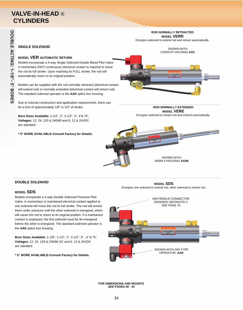
SINGLE SOLENOID
MODEL SVS These models incorporate a 4-way Single Solenoid Pilot Valve, air return. A maintained electrical contact is required to move the rods its full stroke. Breaking the electrical contact returns the rod to its original position.
Models can be supplied with the rod normally retracted (electrical contact will extend rod) or normally extended (electrical contact will retract rod).
The standard solenoid operator, is the AAS Splice box housing.
Bore Sizes Available: 1-1/8”, 1-1/2”, 2”, 2-1/2”, 3”, 4” & *5. Voltages: 12, 24,120 & 240/60 AC and 6, 12 & 24VDC are standard.
* 5” BORE AVAILABLE-Consult Factory for Details.
SINGLE SOLENOID
MODEL SVEVA These models incorporate a 4-way Single Solenoid Double Bleed Pilot Valve. A momentary (NOT continuous) electrical contact is re- quired to move the rod its full stroke. A Bleeder Valve, such as the Allenair BV100 or BV-1/8 (to be ordered separately), must be con- nected to the spool cap opposite the solenoid. Depressing this Bleeder Valve momentarily will return the rod to its original position.
Models can be supplied with the rod normally retracted (electrical contact will extend rod) or normally extended (electrical contact will retract rod). The standard solenoid operator, as shown is the AAS splice box housing.
Bore Sizes Available: 1-1/8”, 1-1/2”, 2”, 2-1/2”, 3”, 4” & *5”. Voltages: 12, 24, 120 & 240/60 AC and 6, 12 & 24VDC Are standard.
* 5” BORE AVAILABLE-Consult Factory for Details.
FOR DIMENSIONS AND MOUNTS SEE PAGES 40 - 44
AVAILABLE IN TYPES “AV”, “CV”, “EV” & “EVT”
ROD NORMALLY RETRACTED MODEL SVSR Energize solenoid to extend rod, de-energize solenoid to retract rod.
SHOWN WITH NEMA 4 / IP56 JIC WATERTIGHT HOUSING
ROD NORMALLY EXTENDED MODEL SVSE Energize solenoid to retract rod, de-energize solenoid to extend rod.
SHOWN WITH SPLICE BOX HOUSING AAS
ROD NORMALLY RETRACTED MODEL SVEVAR Energize solenoid to extend rod, manual bleed signal to retract rod.
OPTIONAL BLEEDER VALVE RETRACTS ROD
ROD NORMALLY EXTENDED MODEL SVEVAE Energize solenoid to retract rod, manual bleed signal to extend rod.
OPTIONAL BLEEDER VALVE EXTENDS ROD
SHOWN WITH EXPLOSION-PROOF HOUSING AAX
33
DOUBLE ACTING: 1
-1/8”- 5
” BORES
VALVE-IN-HEAD ® CYLINDERS
SINGLE SOLENOID
MODEL VER AUTOMATIC RETURN Models incorporate a 4-way Single Solenoid Double Bleed Pilot Valve. A momentary (NOT continuous) electrical contact is required to move the rod its full stroke. Upon reaching its FULL stroke, the rod will automatically return to its original position.
Models can be supplied with the rod normally retracted (electrical contact will extend rod) or normally extended (electrical contact will retract rod). The standard solenoid operator is the AAS splice box housing.
Due to internal construction and application requirements, there can be a loss of approximately 1/8” to 1/4” of stroke.
Bore Sizes Available: 1-1/2”, 2”, 2-1/2”, 3”, 4”& *5”. Voltages: 12, 24, 120 & 240/60 and 6, 12 & 24VDC are standard.
* 5” BORE AVAILABLE-Consult Factory for Details.
DOUBLE SOLENOID
MODEL SDS Models incorporate a 4-way Double Solenoid Pressure Pilot Valve. A momentary or maintained electrical contact applied to one solenoid will move the rod its full stroke. The rod will remain there under pressure until the other solenoid is energized, which will cause the rod to return to its original position. If a maintained contact is employed, the first solenoid must be de-energized before the other is energized. The standard solenoid operator is the AAS splice box housing.
Bore Sizes Available: 1-1/8”, 1-1/2”, 2”, 2-1/2”, 3” , 4” & *5”. Voltages: 12, 24, 120 & 240/60 AC and 6, 12 & 24VDC are standard.
ROD NORMALLY RETRACTED MODEL VERR
Energize solenoid to extend rod and retract automatically.
SHOWN WITH CONDUIT HOUSING AAC
ROD NORMALLY EXTENDED MODEL VERE
Energize solenoid to retract rod and extend automatically.
SHOWN WITH NEMA 6 HOUSING AAN6
MODEL SDS Energize one solenoid to extend rod, other solenoid to retract rod.
DIN FEMALE CONNECTOR ORDERED SEPARATELY
SEE PAGE 75
SHOWN WITH DIN-TYPE
* 5” BORE AVAILABLE-Consult Factory for Details.
FOR DIMENSIONS AND MOUNTS SEE PAGES 40 - 44
OPERATOR AAD
34

DOUBLE ACTIN
G: 1
-1/8”- 5
” B
ORES
VALVE-IN-HEAD ® CYLINDERS
SINGLE PILOT MODEL APSRR ROD NORMALLY RETRACTED
MODEL APSR Models incorporate a 4-way Single Pressure Pilot Valve. A continuous pilot pressure applied to “IN” side of valve will move rod its full stroke. When the pilot pressure is released, the rod will return to its original position. Pilot pressure is normally supplied through an optional 3-way N.C. Valve.
PILOT PRESSURE EXTENDS ROD
Models can be supplied with the rod normally retracted (pilot pressure to extend rod) or normally extended (pilot pressure to retract rod). The pilot pressure must be at least 75% of the operating pressure.
Bore Sizes Available: 1-1/8”, 1-1/2”, 2”, 2-1/2”, 3” , 4” & *5”.
* 5” BORE AVAILABLE-Consult Factory for Details.
MODEL APSRE ROD NORMALLY EXTENDED
PILOT PRESSURE RETRACTS ROD
MODEL VARR ROD NORMALLY RETRACTED
BV100
BLEEDER VALVE EXTENDS ROD
SINGLE PILOT
MODEL VAR AUTOMATIC RETURN Models incorporate a 4-way Double Bleed Pilot Valve. A momentary (NOT continuous) actuation of Bleeder Valve is required to move the rod its full stroke. Upon reaching its FULL stroke, the rod will automatically return to its original position.
Models can be supplied with the rod normally retracted (manual bleed to extend rod) or normally extended (manual bleed to retract rod). Due to internal construction and application requirements, there can be a loss of approximately 1/8” to 1/4” of stroke.
Bleeder Valve Model BV100 is supplied on these models.
Bore Sizes Available: 1-1/2”, 2”, 2-1/2”, 3” & 4”.
MODEL VARE ROD NORMALLY EXTENDED
BLEEDER VALVE RETRACTS ROD
BV100
FOR DIMENSIONS AND MOUNTS SEE PAGES 40 - 44
35

DOUBLE ACTIN
G: 1
-1/8”- 5
” B
ORES
VALVE-IN-HEAD ® CYLINDERS
DOUBLE PILOT
MODEL AP This model incorporates a 4-way Double Pressure Pilot Valve. A momentary or maintained pilot pressure applied to one side of the valve will move the rod its full stroke. The rod will remain in that position under pressure until a pilot pressure is applied to the other side, which will cause the rod to return to its original position. If a maintained pilot pressure is applied, it must be released before the other pilot pressure is applied. Pilot pressure must be at least 25% of the operating pressure.
Bore Sizes Available: 1-1/8”, 1-1/2”, 2”, 2-1/2”, 3”, 4” & *5”.
* 5” BORE AVAILABLE-Consult Factory for Details.
DOUBLE PILOT
MODEL SVA This model incorporates a 4-way Double Bleed Pilot Valve. A Bleeder Valve, such as the Allenair BV100 or BV-1/8 (to be ordered separately) must be connected to each spool cap. Depressing one Bleeder Valve momentarily will move the rod its full stroke. Depressing the other Bleeder Valve momentarily will return the rod to its original position.
Bore Sizes Available: 1-1/8”, 1-1/2”, 2”, 2-1/2”, 3”, 4” & *5”.
* 5” BORE AVAILABLE-Consult Factory for Details.
MANUALLY OPERATED
The following 3 models incorporate a 4-way Manual Valve. Bore Sizes Available: 1-1/8”, 1-1/2”, 2”, 2-1/2”, 3”, 4” & *5”.
* 5” BORE AVAILABLE-Consult Factory for Details.
MODEL VH: This model requires manual operation of the lever to both extend and retract the rod.
MODEL VHSRR: This model is lever operated to extend the normally retracted rod. The valve is equipped with a built-in air return which automatically retracts the rod when lever is released.
MODEL VHSRE: This model is lever operated to retract the normally extended rod. The valve is equipped with a built-in air return which automatically extends the rod when lever is released.
PILOT PRESSURE RETRACTS ROD
PILOT PRESSURE EXTENDS ROD
BLEEDER VALVE EXTENDS ROD
BLEEDER VALVE RETRACTS ROD
360°
MODEL VH SHOWN
NOTE: The Lever Assembly is fully adjustable inboth the vertical and horizontal planes.
FOR DIMENSIONS AND MOUNTS SEE PAGES 40 - 44
36

DOUBLE ACTIN
G: 1
-1/8”- 5
” B
ORES
E AT EXTRA COST)
VELY CUSHIONED. FULL REVERSE FLOW PROVIDED. CYLINDER
VALVE-IN-HEAD ® CYLINDERS
AUTOMATIC RECIPROCATING
MODEL VCR This model incorporates a 4-way Double Bleed Pilot Valve. By means of Built-in Bleeder Valves and internal Cam Bosses, this unit will automatically reciprocate as soon as air pressure is applied. Because of this, it is recommended that a shut-off valve be mounted in the inlet line. Due to internal construction and application requirements, there can be a loss of approximately 1/4” to 1/2” of stroke. Minimum stroke available is 1/2”.
Bore Sizes Available: 1-1/2”, 2”, 2-1/2”, 3” & 4”.
STANDARD OPTIONS (CYLINDERS) (AVAILABL
CUSHIONS LAST 1/2 INCH OF STROKE lS EFFECTILENGTH NOT AFFECTED.
SPECIFY FC (FRONT CUSHION)
RC (REAR CUSHION)
BC (CUSHION BOTH ENDS)
NOTES: 1) Dim. B cushion screw shown fully closed. 2) Non-Standard Cushion Adjusting Screw locations
available at slight additional cost.
AVAILABILITY AND TYPES
ADJ = ADJUSTABLE CUSHION AVAILABLE FX = FIXED CUSHION ONLY AVAILABLE NA = NO CUSHION AVAILABLE
NOTES: 1) Fixed Cushions are INTERNALLY constructed. 2) When required Cushions are installed on rear section of Type “EVT” Cylinders.
OVERSIZED RODS SPECIFY OS
ROD WIPER SPECIFY WR Rod Wiper removes dust, dirt and chips from the piston rod on the retracting stroke.
HIGH TEMPERATURE SEALS (CYLINDER & VALVE) SPECIFY HTP Seals are a fluorocarbon compound (viton) and have an operating temperature range of +10°F to +350°F. They will function at temperatures up to +400°F with reduced life but not recommended. On solenoid operated units the core plunger is also supplied with viton seats.
37

DOUBLE ACTIN
G: 1
-1/8”- 5
” B
ORES
VALVE-IN-HEAD ® OPTIONS
NO TANG
SPECIFY NT These Cylinders are available without the Tang section (covered by dimension “E”) at no extra charge. Suggested when Nose or Trunnion Mounting.
DOUBLE ROD PACKINGS SPECIFY DRP For all Type "AV" Cylinders, a second set of rod seals is available for Heavy-duty applications. Note: Not available on 1-1/8" bore size.
STAINLESS STEEL RETAINING RINGS SPECIFY Q Recommended for extremely damp or corrosive environments.
STANDARD OPTIONS (VALVES) (AVAILABLE AT EXTRA COST)
MANUAL OVER-RIDE LEVER SPECIFY OR Non-locking Manual Over-Ride Levers are available on solenoid operated units. They are particularly useful for set-up or electrical failure.
SOLENOID OPERATORS
AAC CONDUIT HOUSING, UL & CSA Listed.
AAD DIN-type HOUSING with a male connector configuration of DIN 43650/ISO 4400. See page 75 for female connectors.
AAG GROMMET HOUSING, UL & CSA Listed.
AAS SPLICE BOX HOUSING (STANDARD), UL & CSA Listed.
AAX EXPLOSION PROOF, UL Listed covering Class I Groups C & D (NEMA 7) and Class II Groups E, F & G (NEMA 9).
AAY SPADE TERMINALS, UL & CSA Listed.
JIC NEMA 4/IP-56
AAN6 NEMA 6
SPECIAL VOLTAGES A wide range of non-standard voltages are available. Specify voltage required.
PIPED EXHAUST ADAPTERS SPECIFY PE Adapters are available which screw into the solenoid plunger housing, enabling
the solenoid exhaust to be piped from the actuator.
38

DOUBLE ACTIN
G: 1
-1/8”- 5
” B
ORES
VALVE-IN-HEAD ®
OPTIONS
MATERIALS Special seal compounds are available for a wide range of fluid media and environments. Tubes, Front Heads, Pistons and Rodscan be supplied plated, hard coated or in other materials.
Please consult the factory for these special requirements, stating quantity required.
MODIFICATIONS Listed below are some of the many modifications Allenair makes daily.
RODS: SPECIFY Non-Standard Rod Extensions............ ("H" Dim.)……... Length RequiredNon-Standard Rod Threads................. ("CC" Dim.)…… Size RequiredNon-Standard Rod Thread Length...... ("J" Dim.)……… Length RequiredFemale Threads on Rod…………………………………... Size & Depth RequiredNo Threads on Rod………………………………………... No ThreadsComplete Special Rod End Configuration………………. Print from Customer RequiredNon-Standard Wrench Flats………………………………. Location and SizeSpecial Rod Material………………………………………. Material Required
FRONT HEAD: Non-Standard Cushion Adj. Screw Location & Extra Ports} Print from Customer required showing full details.
REAR HEAD: Non-Standard Cushion Adj. Screw Location & Extra Ports} Print from Customer required showing full details.Non-Standard Swivel Hole in Tang.................(“Z” Dim.)…..Size RequiredTang 90° from Standard……………………………………….90° Tang
SPECIAL DESIGNS Many times Allenair is able to change the standard configuration of our Cylinders to meet Customer’s special requirements. A print from the Customer is needed so we can evaluate and properly quote on such specials.
PLEASE CONSULT FACTORY ON THE ABOVE SPECIALS STATING QUANTITIES REQUIRED.
ORDERING PROCEDURE TYPE
SEE PAGE 32
BORE SIZE
SPECIFY
STROKE
SPECIFY
CYLINDER OPTIONS
SEE PAGES 37,38,39,49,50,51
& 52
MODEL
SEE PAGES 33,34,35,36
& 37
VALVE OPTIONS
SEE PAGE 38
VOLTAGE
SPECIFY
CUSTOMER SPECIAL
WHEN REQ’D
EXAMPLE: EV 3 X 8 BC IB OS RG SDS AAX OR 120/60 CS List all Cylinder and Valve Options alphabetically
CODE LETTERS DESIGNATION BC………………………. Cushions Both EndsIB……………………….. AB Accessory Pin Installed in Both EndsOS……………………… Oversized RodRG……………………… Outboard Rod Guide InstalledAAX…………………….. Explosion Proof Solenoid OperatorOR……………………… Manual Over-Ride LeaverCS………………………. Special per Customers Specifications
39
DOUBLE ACTING: 1
-1/8”- 5
” BORES
ALVE-IN-HEAD ®
IMENSIONS
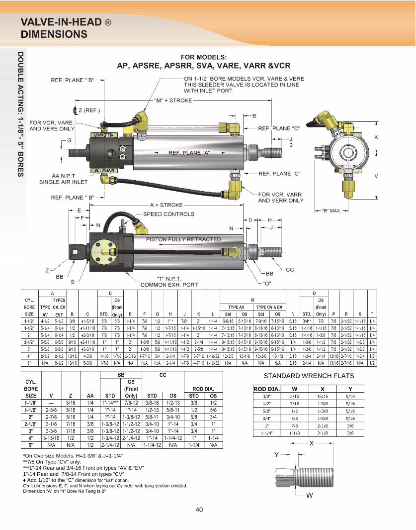
FOR MODELS:
AP, APSRE, APSRR, SVA, VARE, VARR &VCR
- -
- -- -
VD
STANDARD WRENCH FLATS
*On Oversize Models, H=1 3/8” & J=1 1/4” **7/8 On Type “CV” only. ***1” 14 Rear and 3/4 16 Front on types “AV & “EV” 1” 14 Rear and 7/8 14 Front on types “CV” ♦ Add 1/16” to the “C” dimension for “BU” option. Omit dimensions E, F, and N when laying out Cylinder with tang section omitted. Dimension “A” on “4” Bore No Tang is 8”
40

DOUBLE ACTING: 1
-1/8”- 5
” BORES
For AAS, AAX and JIC housing dimensions see below and for AAG dimensions see Right side.
VALVE-IN-HEAD ® DIMENSIONS
FOR MODELS: SVSE
SVEVAR VERR
ALL OPERATORS
To complete drawings of above models, simply match reference planes "A" and "B" with those on the top view of the master drawing on page 40
FOR MODELS: SDS
ALL OPERATORS
FOR MODELS: SVSR
SVEVAE VERE
ALL OPERATORS
To complete drawings of above models, simply match reference planes "A" and "B" with those on the top view of the master drawing on page 40
For AAC housing dimensions see left side of page. for JIC and AAX dimensions see below.
To complete drawings of above models, simply match reference planes "A" and "B" with those on the top view of the master drawing on page 40 For AAC and AAG housing dimensions see above and for JIC dimensions look to the left.
41

DOUBLE ACTING: 1
-1/8”- 5
” BORES
ENSIONS
FOR TYPE EVT
ILLUSTRATED ON PAGE 40.
VALVE-IN-HEAD ® DIM
FOR MODELS: VH , VHSRE & VHSRR
To complete drawings of above models, simply match reference planes “A” and “B” with those on the top view of the master drawing on page 40.
360°
NOTES: 1) FOR MODEL VHSRR THE HANDLE ASSEMBLY IS LOCATED ON THE LEFT SIDE 2) THE HANDLE HAS A 180° ADJUSTMENT AND MAY BE ROTATED TO ANY POSITION ABOUT REF. PLANE “B” 3) FOR ALL MODELS WHEN USED WITH 4” & 5” BORE CYLINDERS, DIMENSION “A” & “M” ARE 9/16 LESS THAN THOSE
CENTER OF PIVOT BUSHING
To complete drawings of Tandem unit, simply match reference planes “A” and “C” with those on the top view of the master drawing on page 40.
42

DOUBLE ACTING: 1
-1/8”- 5
” BORES
-
FrRpr
VALVE-IN-HEAD ® MOUNTS
♦Type “CV” Standard Cylinders use OS Mount or Mounting Nut for front. *For Front Head Only. Rear takes A 214.
MOUNTING NUTS Mounting Nuts are supplied only with Flange or Foot Mounts and are included in the price of those Mounts. However, they may be purchased as a separate item.
MOUNTING BRACKET DIMENSIONS FOOT MOUNT
FLANGE MOUNT FRONT OR REAR
ont Flange Mounting NT Option suggested ear Flange Mounting J2 Option suggested ovides Tang flush with flange mounting surface.
43

VALVE-IN
-HEAD M
OUNTS
VALVE-IN-HEAD ® MOUNTS
ROD CLEVIS, NUT & PIN
*Order A-445
SWIVEL BRACKET
TRUNNION MOUNT
BU OPTION REQUIRED NT OPTION SUGGESTED
BLOCK MOUNT
BU OPTION REQUIRED NT OPTION SUGGESTED
44

SINGLE-ACTIVALVE-IN-HEA
CYLINDE
TYPE AVSA
SINGLE-ACTING 1-1/8” BORE
NG D ® RS
TYPE AVSR
TYPE AVSRR
A continuous electrical contact is required to fully extend the rod, which will remain extended until the electrical contact is broken. An external force is required to return the rod to its original position. A 1/8” N.P.T. port is provided in the front head to permit the return of the rod by means of a separate air supply when required. This port can also be used to install a Flow Control Valve to control forward speed. Standard stroke lengths are whole inch increments from 1" through 20” and 1/2", 1-1/2", 2-1/2" and 3-1/2" . Special strokes available from 1/8” to 80” maximum.
ROD NORMALLY RETRACTED A continuous electrical contact is required to fully extend the rod, which will remain extended until the electrical contact is broken. An internal spring will return the rod to its fully retracted position. SPRING FORCE: 17 LBS. AT REST, 40 LBS. FULL STROKE. Standard stroke lengths are whole inch increments from 1" through 10” and 1/2", 1-1/2", 2-1/2" & 3-1/2” Special strokes available from 1/4” to 10” maximum.
ROD NORMALLY EXTENDED A continuous electrical contact is required to fully retract the rod, which will remain retracted until the electrical contact is broken. An internal spring will return the rod to its fully extended position. SPRING FORCE: 17 LBS. AT REST, 40 LBS. FULL STROKE. Standard stroke lengths are whole inch increments from 1" through 10” and 1/2", 1-1/2", 2-1/2" and 3-1/2" . Special strokes available from 1/4” to 10” maximum.
NOTE: On above types the normal actuation may be reversed by using the optional PE adaptor as the air inlet.
OPTIONS For available options, please see Pages 37, 38, and 39. Cushions not available on these cylinders.
ORDERING PROCEDURE
TYPE SEE ABOVE
BORE 1-1/8” ONLY
STROKE SPECIFY
CYLINDER OPTIONS
SEE PAGES 37, 38,39
VALVE OPTIONS
SEE PAGE 38
VOLTAGE SPECIFY
CUSTOMER SPECIAL
WHEN REQ’D
EXAMPLE: AVSR 1-1/8 X 4 OS RG AAS OR 120/60 CS CODE LETTERS DESIGNATION
OS…………… Oversized Rod RG…………… Outboard Rod Guide InstalledAAS………….. Standard Splice Box HousingOR…………… Manual Over-Ride Leaver
NOTE: List all Cylinder and Valve Options alphabetically.
45
AIR INLET
ALLENAIR “TIME-A-VALVE”® See page 80.
Cylinders are available with 1-1/8” bore only. They are Single Acting Cylinders controlled by a 3-way Single Solenoid Valve mounted to the rear head of the units. The standard solenoid operator (as shown) is the AAS splice box housing. A general purpose conduit housing (AAC) is also available. Most common AC & DC voltages are available. 12, 24, 120 & 240/60 and 6, 12 & 24/DC are standard. The basic construction is the same as our 1-1/8” bore Type "A" Cylinders.

ALVE-IN-HEAD MENSIONS
SINGLE-ACTING 1-1/8” BORE
NOTE: MOUNTING NUT IS SUPPLIED
SINGLE-ACTING ® VDI
HOUSING CAN BE
ROTATED 360°
SPLICE BOX HOUSING
(AAS) SHOWN
MOUNTING BRACKET PART NUMBERS
* BU OPTION REQUIRED
FOR MOUNTING BRACKET DIMENSION SEE PAGES 20 & 21
46
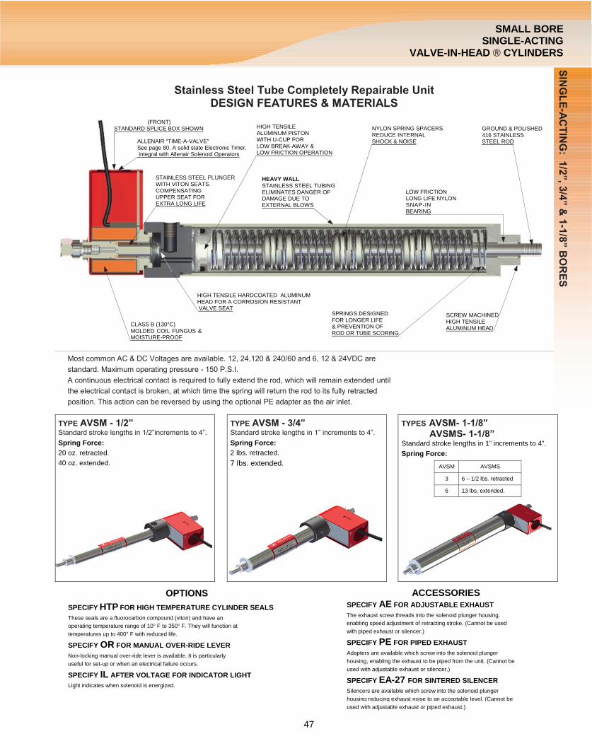
Stainless Steel Tube Completely Repairable Unit DESIGN FEATURES & MATERIALS
Most common AC & DC Voltages are available. 12, 24,120 & 240/60 and 6, 12 & 24VDC are
standard. Maximum operating pressure - 150 P.S.I.
A continuous electrical contact is required to fully extend the rod, which will remain extended until
the electrical contact is broken, at which time the spring will return the rod to its fully retracted
position. This action can be reversed by using the optional PE adapter as the air inlet.
TYPE AVSM - 1/2” Standard stroke lengths in 1/2”increments to 4”.
TYPE AVSM - 3/4” Standard stroke lengths in 1” increments to 4”.
TYPES AVSM- 1-1/8” AVSMS- 1-1/8”
PLUNGER S.
D
SINGLE-ACTING: 1
/2”, 3/4” & 1-1/8” BORES
SMALL BORE SINGLE-ACTING
VALVE-IN-HEAD ® CYLINDERS
(FRONT) STANDARD SPLICE BOX SHOWN
ALLENAIR “TIME-A-VALVE” See page 80. A solid state Electronic Timer, integral with Allenair Solenoid Operators
STAINLESS STEELWITH VITON SEAT COMPENSATING UPPER SEAT FOR EXTRA LONG LIFE
HIGH TENSILE ALUMINUM PISTON WITH U-CUP FOR LOW BREAK-AWAY & LOW FRICTION OPERATION
HEAVY WALL STAINLESS STEEL TUBING ELIMINATES DANGER OF DAMAGE DUE TO EXTERNAL BLOWS
NYLON SPRING SPACERS REDUCE INTERNAL SHOCK & NOISE
LOW FRICTION LONG LIFE NYLON SNAP-IN BEARING
GROUND & POLISHED 416 STAINLESS STEEL ROD
HIGH TENSILE HARDCOATED ALUMINUM HEAD FOR A CORROSION RESISTANT VALVE SEAT
Spring Force: 20 oz. retracted. 40 oz. extended.
CLASS B (130°C) MOLDED COIL FUNGUS & MOISTURE-PROOF
Spring Force: 2 Ibs. retracted. 7 Ibs. extended.
SPRINGS DESIGNED FOR LONGER LIFE & PREVENTION OF ROD OR TUBE SCORING
SCREW MACHINEHIGH TENSILE ALUMINUM HEAD
Standard stroke lengths in 1” increments to 4”. Spring Force:
AVSM AVSMS
3 6 – 1/2 lbs. retracted
6 13 lbs. extended.
OPTIONS SPECIFY HTP FOR HIGH TEMPERATURE CYLINDER SEALS These seals are a fluorocarbon compound (viton) and have an operating temperature range of 10° F to 350° F. They will function at temperatures up to 400° F with reduced life.
SPECIFY OR FOR MANUAL OVER-RIDE LEVER Non-locking manual over-ride lever is available. It is particularly useful for set-up or when an electrical failure occurs.
SPECIFY IL AFTER VOLTAGE FOR INDICATOR LIGHT Light indicates when solenoid is energized.
ACCESSORIES SPECIFY AE FOR ADJUSTABLE EXHAUST The exhaust screw threads into the solenoid plunger housing, enabling speed adjustment of retracting stroke. (Cannot be used with piped exhaust or silencer.)
SPECIFY PE FOR PIPED EXHAUST Adapters are available which screw into the solenoid plunger housing, enabling the exhaust to be piped from the unit. (Cannot be used with adjustable exhaust or silencer.)
SPECIFY EA-27 FOR SINTERED SILENCER Silencers are available which screw into the solenoid plunger housing reducing exhaust noise to an acceptable level. (Cannot be used with adjustable exhaust or piped exhaust.)
47

SMALL BORE SINGLE-ACTING VALVE-IN
-HEAD CYLINDERS
TYPE BORE STROKE OPTIONS (list alphabetically) VOLTAGE
EXAMPLE: AVSM 3/4 X 4 - AE - OR - 24/VDC
DIMENSIONS
ORDER MOUNTS SEPARATELY- SHOWN BELOW
MOUNTING BRACKETS
NOTES: FRON
NUT I
SMALL BORE SINGLE-ACTING VALVE-IN-HEAD ® CYLINDERS
ORDERING PROCEDURE
T NOSE MOUNTING S PROVIDED WITH EACH CYLINDER
NOTE: * Foot Mounts will be sold only in pairs, (Front & Rear). Rear Foot Mount slips over tube, (“C” Dia.).
FOOT MOUNT FLANGE MOUNT ROD CLEVIS, NUT & PIN
48