v t t t i e d o t t e i t a product data management (pdm). … · 2020-03-09 · sql structured...
TRANSCRIPT

VT
T R
ESE
AR
CH
NO
TE
S 2042Product D
ata Managem
ent (PDM
). Design, exchange and integration view
points
V T
T
T I
E D
O T
T E
I T
A2 0 4 2
Jukka Kääriäinen, Pekka Savolainen,Jorma Taramaa & Kari Leppälä
Product Data Management (PDM)Design, exchange and integrationviewpoints
V T T R E S E A R C H N O T E S
Tätä julkaisua myy Denna publikation säljs av This publication is available from
VTT TIETOPALVELU VTT INFORMATIONSTJÄNST VTT INFORMATION SERVICEPL 2000 PB 2000 P.O.Box 2000
02044 VTT 02044 VTT FIN–02044 VTT, FinlandPuh. (09) 456 4404 Tel. (09) 456 4404 Phone internat. + 358 9 456 4404Faksi (09) 456 4374 Fax (09) 456 4374 Fax + 358 9 456 4374
New products have become complex and their design processes produce moreand more data. The economical success of manufacturing companies depends onhow well they can detect customers' needs and how quickly they can respondto these needs by producing a product that meets these needs. The design processrequires specialists from many disciplines. In addition, companies must globalisedesign and manufacturing, and operate without the restrictions of physicaldistance or time.
This report describes the requirements of the embedded product's designdata management. Analysis covers different product technologies as well asdevelopment processes. The challenge of design data management is to mana-ge the total set of data related to the structure of the product during theproduct's life-cycle.
The result of the analysis is the framework which represents the require-ments for the design data management of an embedded product. This classi-fication contains three subsets: data management, process and life-cycle mana-gement, and data capture and distribution. This framework is used to evaluatethree commercial PDM-systems.
ISBN 951–38–5684–4 (soft back ed.) ISBN 951–38–5685–2 (URL: http://www.inf.vtt.fi/pdf/)ISSN 1235–0605 (soft back ed.) ISSN 1455–0865 (URL: http://www.inf.vtt.fi/pdf/) TECHNICAL RESEARCH CENTRE OF FINLAND ESPOO 2000
DataDataDataDatamanagementmanagementmanagementmanagement
Data capture & distribution
Process andProcess andProcess andProcess andlife cyclelife cyclelife cyclelife cycle
management management management management

VTT TIEDOTTEITA – MEDDELANDEN – RESEARCH NOTES 2042
TECHNICAL RESEARCH CENTRE OF FINLANDESPOO 2000
Product Data Management (PDM)
Design, exchange and integrationviewpoints
Jukka Kääriäinen, Pekka Savolainen,Jorma Taramaa & Kari Leppälä
VTT Electronics

ISBN 951–38–5684–4 (soft back ed.)ISSN 1235–0605 (soft back ed.)
ISBN 951–38–5685–2 (URL:http://www.inf.vtt.fi/pdf)ISSN 1455–0865 (URL:http://www.inf.vtt.fi/pdf)
Copyright © Valtion teknillinen tutkimuskeskus (VTT) 2000
JULKAISIJA – UTGIVARE – PUBLISHER
Valtion teknillinen tutkimuskeskus (VTT), Vuorimiehentie 5, PL 2000, 02044 VTTpuh. vaihde (09) 4561, faksi (09) 456 4374
Statens tekniska forskningscentral (VTT), Bergsmansvägen 5, PB 2000, 02044 VTTtel. växel (09) 4561, fax (09) 456 4374
Technical Research Centre of Finland (VTT), Vuorimiehentie 5, P.O. Box 2000, FIN–02044 VTT, Finlandphone internat. + 358 9 4561, fax + 358 9 456 4374
VTT Elektroniikka, Sulautetut ohjelmistot, Kaitoväylä 1, PL 1100, 90571 OULUpuh. vaihde (08) 551 2111, faksi (08) 551 2320
VTT Elektronik, Inbyggd programvara, Kaitoväylä 1, PB 1100, 90571 ULEÅBORGtel. växel (08) 551 2111, fax (08) 551 2320
VTT Electronics, Embedded Software, Kaitoväylä 1, P.O. Box 1100, FIN–90571 OULU, Finlandphone internat. + 358 8 551 2111, fax + 358 8 551 2320
Technical editing Leena Ukskoski
Otamedia Oy, Espoo 2000

3
Kääriäinen, Jukka, Savolainen, Pekka, Taramaa, Jorma & Leppälä, Kari. Product Data Management(PDM). Design, exchange and integration viewpoints. Espoo 2000, Technical Research Centre ofFinland, VTT Tiedotteita – Meddelanden – Research Notes 2042. 104 p.
Keywords design data management, embedded product design
Abstract
The electronics and electrical industries have become an important branch of industry inFinland. They produce products which are used in health care, industry, and every-dayliving such as mobile phones, industrial instruments and automotive electronics.
In the global markets there are many competitors and companies seeking new ways todecrease costs. This hard competition forces companies to specialise and focus on acertain market-segment. Products are containing more functionality, and productdevelopment is a continuous process to fulfil customer needs. Developers have tomaster a range of technology and the total amount of product data is increasing.
This report describes the requirements of the embedded product's design datamanagement. Analysis covers different product technologies as well as developmentprocesses. The challenge of the design data management is to manage the total set ofdata related to the structure of the product during the product's life-cycle.
The result of the analysis is the framework which represents the requirements of thedesign data management of the embedded product. This classification contains threesubsets: data management, process and life-cycle management, and data capture anddistribution.
This framework is used to evaluate three commercial PDM systems. This considerationbrings out the fact that the current solutions do not meet all the requirements of theembedded product's design data management.

4
Preface
This report is a part of VTT Electronics’ strategic PRIMA (PRoduct InformationMAnagement for the electronics industry) project, which deals with product datamanagement in the electronics industry. This report presents the concept of product datamanagement in the electronics industry.
I would like to thank VTT Electronics and all the people who have helped me duringthis research and have thereby made this research possible. I would also like to thankPDM systems resellers who have kindly introduced their solutions:
Risto Kause from Parametric Technology Finland Oy,
Hannu Lehtimäki from Ideal Product Data Oy, and
Tuomo Kähkönen and Kari Kakkonen from Software Engineering Center SEC Oy.
Furthermore, I want to thank my supervisors: Embedded Product Data Management –research group Section Manager Pekka Savolainen, and Professor Martti Penttonen ofthe University of Kuopio. I would also like to thank Dr. Jorma Taramaa and Dr. KariLeppälä who have helped me during this work.
I would like to give my special thanks to my fiancée, Kati, and my parents, who havesupported me during my studies.
Jukka Kääriäinen

5
Contents
Abstract..............................................................................................................................3
Preface ...............................................................................................................................4
List of abbreviations ..........................................................................................................7
1. Introduction..................................................................................................................91.1 Background.........................................................................................................91.2 Related research and research problems...........................................................101.3 Structure of the report.......................................................................................11
2. Overview of embedded product design .....................................................................132.1 Design for manufacture ....................................................................................132.2 Design of embedded products ..........................................................................142.3 Technical design disciplines and document management................................17
2.3.1 Software design...........................................................................................172.3.2 Electronics design .......................................................................................182.3.3 Software-hardware co-design .....................................................................212.3.4 Mechanical design ......................................................................................22
2.4 Concurrent engineering ....................................................................................232.5 Design data management..................................................................................24
3. PDM systems .............................................................................................................283.1 Product Data Management (PDM)...................................................................283.2 State-of-the-art trends of PDM.........................................................................32
4. Data exchange............................................................................................................354.1 Data formats and translators in data exchange .................................................354.2 STEP (STandard for the Exchange of Product model data).............................374.3 CDIF (Case Data Interchange Format).............................................................424.4 SGML (Standard Generalized Markup Language) ..........................................45
5. Requirements of design data management ................................................................475.1 Introduction ......................................................................................................475.2 Requirements for the embedded product's design data management...............47
5.2.1 Data Management .......................................................................................485.2.2 Process and life-cycle management............................................................495.2.3 Data capture & distribution ........................................................................505.2.4 Support for working methods .....................................................................51
5.3 Requirements for enterprise-level design data management............................53

6
6. Design data management levels.................................................................................566.1 The design data management features of design tools .....................................566.2 Team-level design data management ...............................................................586.3 Enterprise level design data management ........................................................60
7. System review............................................................................................................647.1 Windchill EPDM system..................................................................................64
7.1.1 Windchill 3.0 EPDM system ......................................................................647.1.2 Solutions for design data management .......................................................68
7.2 Metaphase EPDM system.................................................................................777.2.1 Metaphase EPDM system...........................................................................777.2.2 Metaphase solution for design data management .......................................85
7.3 PVCS Dimensions............................................................................................927.3.1 PVCS Dimensions system overview ..........................................................927.3.2 PVCS Dimensions for design data management ........................................93
7.4 Observations .....................................................................................................97
8. Conclusions................................................................................................................98
References .......................................................................................................................99

7
List of abbreviations
List of abbreviations
AP Application ProtocolASCII American Standard Code for Information InterchangeASIC Application Specific Integrated CircuitBOM Bill Of MaterialCAD Computer Aided DesignCAPP Computer Aided Process PlanCASE Computer Aided Software EngineeringCDIF Case Data Interchange FormatCE Concurrent EngineeringCOE Customer Order EntryCORBA Common Object Request Broker ArchitectureDAD Design Automation DivisionDBMS DataBase Management SystemDOCSTEP Product Documentation Creation and Management using STEPDSP Digital Signal ProcessingDTD Document Type DefinitionDVDM Data Vault and Document ManagementDXF Drawing Interchange FormatEAI Enterprise Application IntegrationEBCDIC Extended Binary Coded Decimal Interchange CodeECAD Electronics Computer Aided DesignECP Engineering Change ProposalEDA Electronics Design AutomationEDIF Electronic Design Interchange FormatEDM Engineering Document ManagementEIA Electronics Industry AssociationEIDX Electronics Industry Data ExchangeEIG Electronic Information GroupEPDM Enterprise Product Data ManagementEPM Windchill Enterprise Product ModelerERP Enterprise Resource PlanningFPGA Field Programmable Gate ArrayHTML HyperText Markup LanguageHW HardWareIAD Industrial Automation DivisionIDF Intermediate Data FormatIPDMUG International PDM Users GroupISO International Organisation for StandardisationMCAD Mechanical Computer Aided ManufacturingMETADM Metaphase Document ManagementMETASM Metaphase Storage ManagementMETAVPDM Metaphase Virtual Product Development ManagerNC Numeric ControlOMG Object Management Group

8
PDES Product Data Exchange SpecificationsPDF Portable Document FormatPDM Product Data ManagementPIM Product Information ManagementPM Program ManagementPSM Product Structure ManagementQFD Quality Function DeploymentRDBMS Relational DataBase Management SystemSCCS Source Code Control SystemSCM Software Configuration ManagementSDAI Standard Data Access InterfaceSDRC Structural Dynamics Research CorporationSGML Standard Generalised Markup LanguageSQL Structured Query LanguageSTEP Standard for the Exchange of Product model dataSW SoftWareTDM Technical Document ManagementTIM Technical Information ManagementUML Unified Modeling LanguageURL Uniform Resource LocatorVHDL VHSIC Hardware Description LanguageVTT Technical Research Centre of Finland (Valtion Teknillinen
Tutkimuskeskus)WBS Work Breakdown StructureWPM Workflow and Process ManagementWWW World Wide WebXML Extensible Markup Language

9
1. Introduction
1.1 Background
The development of embedded products requires a range of technologies such assoftware, electronics, and mechanics. Software is typically in close relation withelectronics and mechanics in these products [OiS98]. These intelligent products, whichoften operate in uncontrolled and difficult environments, are called embedded products.The role of the software is important in the electronics industries [Sep97]. Software isincreasingly used e.g. for the control and data transfer functions of the product as wellas the implementation of customised features [Sep97].
The globalisation of design activities requires data exchange with other sites, customers,sub-contractors, and suppliers. The development and use of the product adds concept"life-cycle" to this report. One of the definitions of the life-cycle emphasising softwareis [BeE89]:
The life-cycle is a period of time that starts when a software product is specified andends when the product is no longer available for use.
Product development contains a set of activities, tools, methods, and procedures bywhich customer needs are translated into a product [MaM97]. Figure 1 illustratesinteraction between electronic products and their development processes [Sep97].
Figure 1. Interaction between the product and the product development process [Sep97,p. 69].
P r o d u c t d e v elo p m e n t-s o f tw a re-e le c t ro n i c s-m e ch a n i c s-o th e r te c h n o lo g ie s
Processes
Processim
provement
P ro d u c t io n a n dm a in ten a n c e
E le c tr o n ic p r o d u c t
E n v ir o n m e n t
U s e r

10
Product development is very important in the business activity, and success during thatprocess is important for a company. CimData [MaM97] defines "process" as an orderedsequence of steps performed for a given purpose, such as the software developmentprocess. Development also contains functions like document version control, whichmaintains a document’s version history. Process improvement aims to improveprocesses to meet business goals [OiS98].
The developers of embedded products have to master a range of technologies, e.g.electronics and software. The increasing use of these technologies increases the totalamount of product data [HaH95]. Product data is a set of data which uniquely defines aproduct for the enterprise [MaM97]. This product data contains e.g. drawings, decisions,specifications and calculations which are used in production and maintenance. All thisproduct data should be documented and managed, and documents should be availableeven after decades (maintenance). The operational environment of a company nowadaysalso requires fast time-to-market, co-operation and cost efficiency [HaH95]. Theserequirements create challenges for a company's data management system.
1.2 Related research and research problems
CimData [MaM97] defines the parts of PDM and introduces many commercial PDMsystems. CimData defines PDM as follows [MaM97]:
A Product Data Management system is used within an enterprise to organise, accessand control all data related to its products, and manage the life-cycle of those products.
This report focuses on the design data management. How do PDM systems manage aproduct's design, data exchange and tool integration? However, at the same time it isworth noticing that PDM's scope is even broader.
Halttunen & Hokkanen [HaH95] have examined the background and solutions related toPDM, as well as PDM in product planning and production. Halttunen & Hokkanen alsointroduce the ways in which PDM can support Concurrent Engineering (CE). Whenconsidering the design data management of an embedded product, the management ofembedded software and software documents is one part of a product's wholemanagement [Tar98]. Many design tools and management systems are used during aproduct's design, and interaction between these systems is needed [Har98]. Onepossibility for interaction of these systems is the use of data representation andexchange standards [PeT98] [Sää98].
There are literature and research results available that deal with design datamanagement and product data management [HaL96, PeT98, PiM97]. However, it isdifficult to find a good examination which clearly defines design data managementrequirements in the electronics industry. Thus the definition of these requirements isessential. This report also presents how commercial systems meet these requirements.

11
In conclusion, the aim of this research is to find the answers to the following questions:
• What kinds of demands does the development of multi-technological product(design combines hardware (HW), software (SW) and mechanics) bring into productdata management?
• What kind of solutions can be found to meet these demands (emphasis on the PDMsystems)?
1.3 Structure of the report
The scope of this report was defined to cover the electronics industry. Within thisindustry sector the focus is on embedded product design.
This report has been divided into six chapters according to Figure 2.
Figure 2. Structure of the report.
The first chapter contains an introduction to the problem. This chapter also introducesthe related research. The second chapter concentrates on the general considerations andrequirements of the problem, and introduces the product development process of the
Problem definition(Chapter 1)
Introduction to embeddedproduct design
(Chapter 2)
PDM systems(Chapter 3)
Requirements of designmanagement(Chapter 5)
Design data management levels(Chapter 6)
System reviews(Chapter 7)
Conclusions(Chapter 8)
Data exchange(Chapter 4)
Framework

12
embedded product. The chapter also presents Concurrent Engineering design principlesand the general dimensions of engineering data management. The third chapter presentsPDM definition and some state-of-the-art solutions for PDM. This chapter presents thegeneral requirements for product data management. The fourth chapter introducesseveral standards which are used in data exchange. These standards are: STEP, CDIF,and SGML. The fifth chapter defines special requirements for design data managementof embedded product and presents a framework of these requirements. This frameworkis used in Chapter 7 when commercial PDM systems are analysed. The sixth chapterpresents the levels of design data management (levels of solutions). These levelsrepresent the basic solution categories.
The seventh chapter contains the examination of selected commercial PDM systems andone project management system. The eighth chapter contains conclusions.
The report begins with a literature and article review (Chapter 2), which collectsrequirements for the design data management. Chapter 3 presents the state-of-the-art -section based on literature, articles, and enquiries from PDM vendors. Chapter 4contains the analysis of data exchange problems and solutions according to theliterature. Chapter 5 contains a specific analysis of the problem. Chapter 6 considersdesign data management levels according to the literature. The system review (Chapter7) contains a consideration of product data management systems, how well do theexisting systems meet defined requirements of today. This information has beencollected by interviews and experiments. The PDM resellers who have been interviewedare:
• Parametric Technology Finland, selling Windchill1;
• Software Engineering Center, selling PVCS Dimensions2;
• Ideal Product Data, selling Metaphase3.
These tools represent different backgrounds. Windchill and Metaphase provide supportmainly for mechanical and electrical design tools. PVCS Dimensions provides supportmainly for the software tools.
1 Windchill is a trademark of Windchill Technology Inc.2 PVCS Dimensions is a trademark of MERANT Solutions Inc.3 Metaphase is a registered trademark of Metaphase Technology Inc.

13
2. Overview of embedded product design
The success of manufacturing companies depends on their ability to meet customers'needs and to respond quickly to these needs by introducing new products [UlE95]. Thefollowing sections introduce the role of product design in a manufacturing system. Theyalso introduce product design processes and consider product data managementrequirements.
Section 2.1 introduces product design as one of the activities in the manufacturingsystem. This design process creates information for production, but this information isalso necessary for other functions, e.g. purchasing and sales. Section 2.2 introduces thesystematic design process of an embedded product, starting from requirements analysis,up to the product's maintenance. Three discipline-specific design domains are discussedfurther in Section 2.3 (software, electronics, and mechanics).
The shortening of product life-cycle, and the requirements for variety stress theimportance of the product design phase. Design is always a trade-off between cost,product performance and time to market [Kau99]. The majority of the product's costsare accumulated during the product's design process. This has lead to the evolution ofnew design principles (e.g. concurrent engineering), as well as new requirements forproduct data management [HaH95]. Concurrent engineering is discussed in Section 2.4.Section 2.5 defines general data management requirements for a product's design. Theserequirements do not depend on product implementation technology.
2.1 Design for manufacture
Product design can be seen as a sub-process of the manufacturing function (Figure 3). Itcreates manufacturing support information, such as drawings, assembly instructions andBOM (Bill Of Material). BOM is an ordered list of raw materials, parts, sub-assemblies,and assemblies. This design information contains a description of the product (e.g.design data from Computer Aided Design-tool (CAD)).
Design activities support manufacturing through the application of design principles,often defined as guidelines: modular design, design for simplification, and design foreasy of automation. Modular design uses common components and assemblies inproduct design. Design for simplification tries to include as many standard componentsas possible in a product's structure. Design for ease of automation aims to reduce thecomplexity of the assembling processes [BaB91]. Nowadays, production processplanning is an important part of the whole product's development [Kiv98]. For example,designers have to understand different materials' behaviour and special handling orprocessing requirements for components [PrS92].
An embedded product contains both electronics and software, and embedded softwarehas become an integral part of products. Production costs can be decreased byimplementing products with different features through software [Mil98].

14
Figure 3. The design process as part of the manufacturing system [BaB91, p. 237].
The customer order flow (Figure 3) identifies the production requirements, andmanufacturing planning defines schedules for the product's manufacture. Theseschedules are also used to organise the purchasing of raw materials. The material flowreceives and inspects raw materials and components. Finally, the manufacturing processuses raw materials according to the schedule by using a defined processes tomanufacture the product. [BaB91]
2.2 Design of embedded products
The product development process can be described as a sequence of specific tasks suchas concept design, design, and testing. A traditional state-gate model identifies the maintasks for the development process, and gates which define decisions between the tasks.The stage-gate model provides the basic principle for application of managerial controlon design processes. [Kau99]
Embedded products are complicated multi-technology artefacts, so there is a need for adiscipline which brings different skills, disciplines, development stages andstakeholders together. The systems engineering model was originally created to masterthe creation of very large and complicated defence and computer systems. Systemsengineering provides a comprehensive reference model for the development of newembedded products. Systems engineering can be defined as follows [Joh99]:
An interdisciplinary collaboration approach to derive, evolve, and verify a life-cyclebalanced system solution that satisfies customer's exceptions and meets publicacceptability.
Keller & Shumate defines systems engineering as follows [KeS92]:
ManufacturingplanningPurchasing
Vendor
Receiving Inspection Rawmaterial
Finalproducts Ship Distribute
Customer
Forecast
COE Sales
Marketing
DesignCAD, CAPP
Themanufacturing
process
Productdesignflow
Product flow
Customer order flowPurchase order flow
Material flow

15
Systems engineering is the process used to transform an operational need into aworking system that satisfies the requirements.
Figure 4 illustrates the development process of an embedded product which emphasisesthe systems engineering involvement during the whole design process (modifiedaccording to Keller & Shumate [KeS92]).
Figure 4. The systems development process.
Requirements analysis transfers product requirements into a set of capabilities andperformance requirements, suitable for a refinement of the design process, and forallocation of requirements to components of the design. Also the system qualificationrequirements are developed and documented. The system design defines the overallsystem architecture, which will satisfy the requirements. The discipline-specific designprocesses are running in parallel, but are co-ordinated. The system will then beintegrated and tested. The remaining tasks involve the testing and maintenancefunctions.
Kauppinen [Kau99] divides organisational models of product development into fourtypes: serial, parallel, coupled and concurrent. In a serial process one task must becompleted before the next one can begin. This approach has been criticised, as quickerproduct development cycles are needed. The parallel model can shorten thedevelopment cycle but it demands a clear and detailed description of the tasks. Thecoupled model improves on the parallel model by adding interaction and iterationduring the design process. The concurrent model accelerates sequential tasks byoverlapping, providing interaction and co-ordinating parallel activities.
Changes in customers and production requirements, and refinement of the design taskscan raise a need for product modifications during or after the product developmentprocess. The Engineering Change Management process manages this modificationprocess. Figure 5 describes the Engineering Change process. [BeE89]
An engineering change proposal or request (ECP, ECR) describes the suggestedchanges. It also identifies the related items and documents. These suggestions are thenevaluated. If the change is approved, it should be incorporated, documents updated, andchange tested. Finally all parties should be notified. [BeE89, PeT98, Ber92]
SystemDesign
SystemDesign
Software designSoftware design
Electronicsdesign
Electronicsdesign
Mechanicaldesign
Mechanicaldesign
Systemintegration
test
Systemintegration
test
Other disciplinesOther disciplines
Systemrequirements
analysis
Systemrequirements
analysis
Systemoperational
requirements
Systemoperational
requirements
-Qualification-Test
-Customeracceptance
-Operationaltest and
evaluation
-Qualification-Test
-Customeracceptance
-Operationaltest and
evaluation
MaintenanceMaintenanceC
ontinuedsystem
sengineering
involvement

16
Figure 5. Change control flow [BeE89, p. 129].
Engineering change management can be divided into change information, and actionsneeded to make the change. During the change process people act according to theirroles, e.g. programmer, designer, build manager. For example, after a programmercompletes his/her change task the file is checked back in the system. Then the systemnotifies the test manager, who promotes the file to the test stage. [Wil97]
The engineering change process is a complex iterative process, and the example aboveis simplified. The amount of engineering data is increasing, and concurrent moduleupdates are possible [PeT98]. Engineering and product data management needs to beable to cope with this complex environment [Tar98].
EnhancementProposal
Prepare EngineeringChange Proposal
Evaluate ECP
Notify Originator
Incorporate &test change
Archive ECPUpdate ECP
ProblemReport
ApproveProposal? No
Yes

17
2.3 Technical design disciplines and document management
The design process refines design specifications into discipline-specific designdocuments, which are reviewed in the product design process. In this chapter we discusstechnical design disciplines: software design, electronics design and mechanical design.we also include software/hardware co-design. Naturally, product design may alsocontain parts like motors, sensors, actuators, hydraulics and pneumatics.
2.3.1 Software design
There are several design models, developed specially for software design. They includethe waterfall model [Roy70, Boe76], which divides development into smaller sequentialsteps, and the spiral model [Boe88].
The ISO standard 12207 [Inf95] defines a software life-cycle process within the contextof three main process categories. The processes are divided into five primary processes,eight supporting processes, and four organisational processes. One of the primaryprocesses is software development, which contains the activities and tasks of thedeveloper. The documentation is created according to the documentation process, one ofthe supporting processes. It defines the activities for recording the information producedby a life-cycle process.
Figure 6 [Pes93] describes a simplified software development process which has thesame main phases as the ISO 12207 -standard. This figure also illustrates the parallelactivities of different technologies. All documents during the phases are reviewed.
Figure 6. Software design process as part of systems design.
SystemDesign
SystemDesign
Electronics designElectronics design
Mechanical designMechanical design
Systemintegration
test
Systemintegration
test
Softwarerequirements
analysis
Softwaretop-level
design
Softwaredetailed
design
Code,test andintegrate

18
The system design produces the specifications for software design. Softwarerequirements analysis describes detailed specification of the necessary functionality ofeach software component. Top-level design process explains the top-level structure ofthe software and describes interfaces between the major modules within thatarchitecture. The developer defines preliminary test requirements and the schedule forsoftware integration. Detailed design specifies the detailed structure for each softwarecomponent (e.g. pseudo code) and interfaces between software components and units.The developer also defines preliminary requirements and the schedule for software unitsas well as updating the test requirements and the schedule for software integration. Afterdesign the modules are coded (program code) and tested (results are documented). Thedeveloper updates the test requirements of integration. In the software integration phasethe modules are integrated as the software system and tested so that the software isdeveloped according to the integration plan. The information is documented andreviewed. [Pes93, Inf95]
Saukkonen and Oivo have considered and represented features related to thedevelopment process of embedded software [OiS98]:
• parallel design of hardware and software,
• parallel development of different kinds of software,
• strong product and product data management viewpoint, and
• difference between design and user environments.
The parallel development of electronics hardware and different kinds of software (e.g.man-machine interface software, application software, device drivers, digital signalprocessing (DSP) software) requires good change management, because changes inelectronics can effect the software and vice versa [OiS98]. Working interfaces betweenhardware and software development processes are essential in efficient productdevelopment. As several people usually work in parallel, management of parallelmodifications is also necessary [Leb94]
The embedded software is a part of the product, and even after decades it may becomenecessary to track product configuration information, including software components[OiS98] [Leb94].
Hardware-software co-design is a special type of embedded product design, and it willbe discussed in Section 2.3.3.
2.3.2 Electronics design
The electronics design process creates the description of the electronics parts of theproduct. Part of this information is used to control the production process and its sub-processes, for example assembly drawings (for assembly or assembly machineprogramming) and layout files (to control printed circuit board manufacturing

19
machinery) and parts lists (to control purchasing and material logistics). Design outputsmay be characterised as manufacturing templates and information platforms.
It is typical for electronics that component technology evolves rapidly. Product updatesneed to be made frequently, due the changing situation of component supply andmarkets. Maintenance, for example, needs to track the documents for a proper productconfiguration even after many years. [PeR96]
The next list is based on VTT Electronics’ quality system and represents the mainphases of electronics design [VTT97a]:
• General design of modules: this phase specifies system-level specification andcreates module-level specifications. This phase also produces e.g. the functionaldescriptions of the modules.
• Detailed design of modules: this phase uses system-level and module levelspecifications and produces design documents and test plans.
• Module prototype manufacturing: this phase produces module prototypes, which areused to verify the design.
• Module prototype testing: this phase tests module prototypes.
These phases are common for all types of electronics design from printed circuit boarddesigns up to the design of programmable or application specific microcircuits ASIC).[VTT97a]. Electronics design can include the designing of circuit boards, application-specific integrated circuits (ASIC), or programmable gate arrays. An illustrativeelectronics design flow is shown in Figure 7 (supplemented from [PeR96]).

20
Figure 7. Circuit board design process [PeR96, p. 140].
The details of the electronics are specified using, for example, graphical notation ofhigh level hardware description languages, and nowadays the design is usuallyperformed by means of computer based tools (called e.g. EDA or CAE tools). Thelogical4 design process refers to components located in tool specific componentlibraries. The output of the tool is the netlist, which specifies the components and theirconnections. Simulation is used to check the accuracy of design and the results aredocumented. Logical design also produces a part list and it is possible to export it to aninventory management program.
The layout or physical design uses the netlist to define physical placement for thecomponents and wiring geometry between them. Again, simulation is used to check thedesign. In addition to functional simulation, simulation may involve thermal behaviourand electromagnetic properties. The physical design phase produces placementdiagrams, mechanical drawing of the circuit board, and wiring geometry, which are allreferred to as "layout". All appropriate information will be converted into machinereadable format for circuit board manufacture and for the planning and programming ofassembly operations. [PeR96]
The logical design process for microcircuits is in principle very similar. However, thephysical design phase is different. With application-specific circuits (ASICS), thephysical layout process creates the design (geometry of components and wirings)
4 logical is used to denote "abstract". It may involve analogue or digital (logical) components. For clarity,design with logical circuits is referred as "digital design".
Specification
Layout design
Logical design
Manufacturing information
Partplacement
drawing
Drillinginformation
OtherinformationLayout
Part list
Netlist
Reports
Simulation
Componentlibraries
Simulation
Specifications
Design phase
Document
Circuitdiagram

21
directly on silicon, utilising special design tools. The result of the process is a set ofdesign files, which are delivered to some microcircuit factory.
With programmable logic circuits, the logical design is compiled into programminginformation, which is then used to program the pre-manufactured circuit templates.
Figure 8. Programmable logic circuit design flow [Wik98, p. 51].
2.3.3 Software-hardware co-design
Software and hardware (electronics) can be alternative implementation technologies forsome of the product's functions. Careful software-hardware partitioning is an essentialpart of the design phase. Errors and omissions may lead to difficult and non-optimaldesigns and errors, which will show up in a later phase.
Co-design is defined to be an engineering methodology, which aims at designing thesystem as a whole and achieving shared functionality and performance goals [SoH98,AyJ96], Figure 9.
Specifications
Design entry
Simulation
Implementation Simulation
Production

22
Figure 9. System design methodology supporting co-design [AyJ96, p. 100].
The co-design may be seen as an iterative process, which consists of [Hei97]:
• decomposition: the partition of system function into the collection of sub-functions.
• hardware-software partitioning, which allocates sub-functions onto hardware orsoftware modules.
• refinement: to produce alternative implementations.
• Alternative evaluation: compares individual alternatives and their impact on theoverall system.
Co-design, defined in this way, can be seen as an alternative name for the architecturaldesign phase of the systems engineering process (Chapter 2.2). A narrower definitionfor co-design implies a design cycle, which allows co- simulation. The mainrequirement is that both electronics and software functions are expressed in some high-level programming language, which allows computer simulation of the entire systemfunctionality – either using a uniform or compatible description language for hardwareand software, or using heterogeneous descriptions (in the latter case we deal withmixed-mode simulation) [AyJ96, SoH98].
2.3.4 Mechanical design
The mechanical design process resembles that of electronics design – actually it ishistorically the oldest, and is a paragon for all systematic engineering processes. Thefollowing list is based on VTT Electronics’ quality system and represents main phasesof mechanical design [VTT97b]:
System representation
System partitioning
Codesign
Synthesis
System integration
Decomposition
SW/HW partitioning
Refinement
Alternative evaluation

23
• General design: this phase specifies system-level specification and creates module-level specifications. This phase also produces e.g. module partition and strengthcalculations.
• Industrial design: this phase uses specifications which relate to the industrial designand create aesthetics and ergonomics solutions, which are in harmony with thefunctional requirements of the product.
• Detailed design: this phase uses system level and module level specifications andproduces e.g. design documents, part lists and test plans.
• Module prototype manufacturing: this phase produces module prototypes which areused to verify the design.
• Module prototype testing: this phase tests module prototypes.
Mechanical design naturally requires co-operation with designers of other disciplines.
Mechanical design – like electronics – operates with physical products, and therefore itinteracts with assembly and parts/materials purchasing tasks. Design also createstemplates for production. Usually, some output files of mechanical design are used tocreate NC (Numeric Control) machine tool control programs.
2.4 Concurrent engineering
Concurrent engineering (CE) can be defined as follows [WiP88]:
Concurrent engineering is a systematic approach to the integrated, concurrent designof products and their related processes, including manufacture and support.
Like co-design, concurrent engineering can be seen as one viewpoint to the systemengineering process. It may stress concurrency aspects, for the shortening of the designcycle, or communication aspects, to ensure that all product stakeholders can participatein the early phases of the design process (Figure 10).
Concurrency decreases the design lead-time but also increases the amount ofcommunication. Efficient communication is essential for avoiding unnecessary designchanges and redesigns.

24
Figure 10. Cost of failure in the product engineering process.
2.5 Design data management
Systematic design has two main realms: design processes, and management of designdata. According to Peter Van Hamer and Kees Lepoeter [HaL96], design datamanagement can be divided into five orthogonal dimensions, which are also related tothe processes. These dimensions are common to all technologies:
1. Version
Version dimension divides the results of a design into an order of versions. Usually adesigner has to execute his/her design process iteratively which produces new versions.Engineering changes also produce new versions of the product. Because any earlierversion could be the basis for new modifications, version management leads to a treestructure (Figure 11).
Requirementsspecification
Preliminarydesign
Detaileddesign
Integration Manufacturing
Costs

25
Figure 11. Example of the version tree. Version 6 has been created from version 4 andversion 8 from version 2.
2. Views:
Products can be too complex to be represented by using just one description. There areusually many descriptions of the product and this dimension also has a closerelationship with the design process. The design processes refine the productdescriptions from an abstract level to a more specific representation.
3. Hierarchy:
Products decompose into sub-systems, assemblies, sub-assemblies and parts. Theproduct hiearchy is called the product structure. For example, a printed circuit modulecan be divided into blocks, which represent the sub-systems (Figure 12).
Figure 12. Hierarchical module structure.
V1
V2
V8V3
V7V4
V6V5
M1
M11 M12
M111 M112

26
4. Status:
Status reflects the evolution and control of design documents through the product's life-cycle (Figure 13). The change of the status does not require changes to the informationitself. The engineering organisation has to decide when information meets certainrequirements. Status also has an effect on the information visibility. For example,information with low status can be visible to the team and the same informationpromoted to the higher status can be visible to the department.
Figure 13. The picture illustrates the changes in the design status.
5. Variants:
Variants may be products, which are for example designed for different markets orcomputer programs, which have been designed for different platforms. The terms"version" and "variant" are often confused with each other. The term "version" refers todesign evolution and "variant" to the development of families of related products.
In product engineering, several dimensions to documents and their relations have to beconsidered simultaneously (Figure 14):
Concept Ready Tested Approved
Design Test Review

27
Figure 14. Hierarchical structure where several views exist and each view has severalversions [HaL96, p. 48].
Document management aims to manage documents with respect to differentdimensions. For example, the total amount of product configurations can be enormous.However, not all product configurations are allowed or useful so it is essential to saveall useful baselines. The baseline is a formally reviewed and agreed configuration,which contains all appropriate documents at a certain moment [MaM97]. After thebaseline has been reached, all changes will be made according to the appropriate changeprocess [Ber92]. When the product consists of several technologies, it is essential thatthere is a unifying system which controls the configurations of the product.
Sub-assembly 1View 1
Ver.view1_1
Ver.view1_ 2
Ver.view1_ 3
Ver.view2_1
Ver.view2_2
Ver.view2_3
Ver.view2_4
Ver.view3_1
Ver.view3_2
Sub-assembly 1View 2
Sub-assembly 1View 3
Sub-assembly 1
Assembly
Hierarchy
Concept -design
Logica l-desi gn
Layout-desi gn
Views
Sub-assembly 2

28
3. PDM systems
The enterprise-wide design data management requires management of all product-related design documents which have something to do with product design, productionand maintenance (maintenance needs e.g. assembly documents). The Product DataManagement manages product-related data during a product's whole life-cycle (Figure15) [MaM97]. Section 3.1 introduces the major groups of PDM functions. This sectionprovides the basic classification of PDM functions, which can be used when consideringrequirements for enterprise-level design data management in the electronics industry. Inaddition, Section 3.2 introduces some PDM state-of-the-art trends according to articles,literature, and several PDM vendors.
Figure 15. An example of a product's life-cycle.
The concept PDM is not very well-known. Therefore there are related terms such as[MaM97]:
• Engineering Document Management (EDM),
• Product Information Management (PIM),
• Technical Data Management,
• Technical Document Management (TDM),
• Technical Information Management (TIM).
3.1 Product Data Management (PDM)
The functionality of commercial Product Data Management systems depends on thepurpose of the system. Traditional PDM systems focused on the data vault -function andmanaged mainly mechanical engineering data. This means managing CAD drawings,other picture formats and text documents. The data management capabilities are alsocommon in workgroup systems used by workgroups and teams. In this report a PDMsystem’s functionality contains more than the data vault function and therefore it isreasonable to define parts of the PDM (according CimData) [MaM97]:
R e q u ir e m e n tsd e f in i ti o n
R e q u ir e m e n tsd e f in i ti o n D is p o s a l / re c y c l in gD is p o s a l / re c y c l in gM a i n te n a n c eM a i n te n a n c eP ro d u c t io nP ro d u c t io nD e ta i le d d e s ig nD e ta i le d d e s ig nC o n c e p t d e s ig nC o n c e p t d e s ig n
29
• Data Vault and Document Management,
• Workflow and Process Management,
• Product Structure Management,
• Classification and Retrieval,
• Program Management,
• Communication and Notification,
• Data Transport,
• Data translation,
• Image Services, and
• Administrator services.
The Data Vault and Document Management (DVDM) function is the core functionalityof the system. It offers a secure, controlled storage for all the data (files, forms, etc) andthe metadata, and also a tool for the system administrator. Metadata means data aboutdata. For example, a text document's metadata could be the name of the person whowrote the document, a description about the content, the status of the document (e.g.concept, ready, approved), and the document’s location (also a reference to non-digitaldata is possible). Search functions could use this metadata for information searching. Itis possible to create this metadata by using a PDM system or it could be created byusing a native application (e.g. CAD application). The Data Vault also controls dataaccess with the check-in and check-out function and with the user-managementfunction. The authorised users could check-out documents from the PDM system tomodify them, for example. During modification the other users cannot access thedocument. After modifications the designer checks-in the document back to the system.The Check-in function makes the document "visible" in the system. The system shouldalso allow multiple elements to be associated with the same part or assembly andmaintain version compatibility when elements are changed. A system administrator cantailor the PDM system to meet a company's needs.
The Workflow and Process Management function (WPM) is used with the DVDM-function to create processes (e.g. software development process). WorkflowManagement Coalition [Wor99] defines a term "workflow" as follows:
The automation of a business process, in a whole or part, during which documents,information or tasks are passed from one participant to another for action, according toa set of procedural rules.
So, workflow is a specific representation of a certain process (e.g. sequential tasks).However, the use of concepts (process or workflow) depends on the PDM vendor.Processes can be site-defined (an enterprise or a department defines their own

30
processes) and process management makes sure that different processes will be madeaccording to the site-defined rules (e.g. who is authorised to approve documents). WPMincludes methods for incorporating changes into the released and baselined productdata. The system administrator defines processes and user authorisation.
With the Product Structure Management (PSM) function it is possible to create, manageand maintain part list, assembly, product configuration and bill of material (BOM)structures and link the PDM managed items to these structures (e.g. drawings andsupporting documents). It should also extend these basic structures into a morecomplete product structure, with relationships such as options, versions, substitutes, andeffectivities added. Functionality also enables easy search, access and user-definedview-functions to the structures and items. The system provides graphical viewing (easybrowsing) of the structures and the possibility to link other data items (likespecifications) to the structure. PSM should also allow the user to define alternative,substitute and optional parts within the product structure, likewise a definition of therelationships of the versioned parts. The system administrator creates and maintainsauthorisations to the users to access, create and modify the product structure.
With the Classification and Retrieval function it is possible to define attributes to theproduct data (metadata). The attributes could be related to a part, assembly orrelationship (Figure 16). The authorised users can search parts with these attributes. It isalso possible for a PDM system to organise and present product data according to theseattributes (Figure 17). Modern classification systems also allow the organisation andpresentation of standard parts in a hierarchical manner. These systems allow componentretrieval and reuse.
Figure 16. Attributes in a product structure.
Assembly
Sub-assembly 3Sub-assembly 2Sub-assembly 1
Attribute 1
Attribute 2
Attribute 3
31
Figure 17. Product (document) structure according to authors.
Program Management (PM) offers integrated, computer-based project management. Itsmain function is to create and modify a Work Breakdown Structure (WBS). The WBSincludes major tasks, sub-tasks and detailed tasks. The PM assigns resources andexpenditures to these tasks. The PM allows users to relate detailed WBS tasks with thePDM controlled elements.
Communication and notification is essential for the concurrent design environment.Users should be notified about tasks and changes (perhaps automatically). Also, day-to-day operations need communication. Communication should be possible with thesystem's e-mail application or with external e-mail application (this requires aninterface).
The Data Transport isolates users from the network and operating system commands.The system automatically transports files and other data, even in heterogeneoushardware and software environment, to the user workspace.
The Data translation is essential for achieving an integrated working environment (itprevents isolated islands). The Data transport may also need the data translationfunction when exchanging data between two applications or systems (data exchange).This is made possible by using data translation from one application's format to anotherformat. The use of a neutral standard format is possible (e.g. STEP) and data translationcan be performed automatically before executing the next task during workflowexecution.
The Image Services makes it possible to work with the appropriate picture formats. Thebasic functionality is the view function, which can be used in change review processes.In addition, the user can perhaps redline or edit images.
The System Administrator has a huge role in the implementation of the PDM system.The administrator makes required customisations of the system, defines meta-data andcreates user authorisations. Enabling the distribution of the PDM data is essential inheterogeneous hardware, software and operating systems environments.
When PDM is considered as an information system it is possible to define somerequirements for it based on the development process [PiM96]:
• the information system has to support a work methodology with baselines(document development until a baseline is reached, then the document is frozen),
All documents
Person 1:Documents
Person 2:Documents
Person 3:Documents
32
• the system has to support stage overlapping between product development phases,
• the system must support all documents produced during the project, and
• the system must offer access to this data.
3.2 State-of-the-art trends of PDM
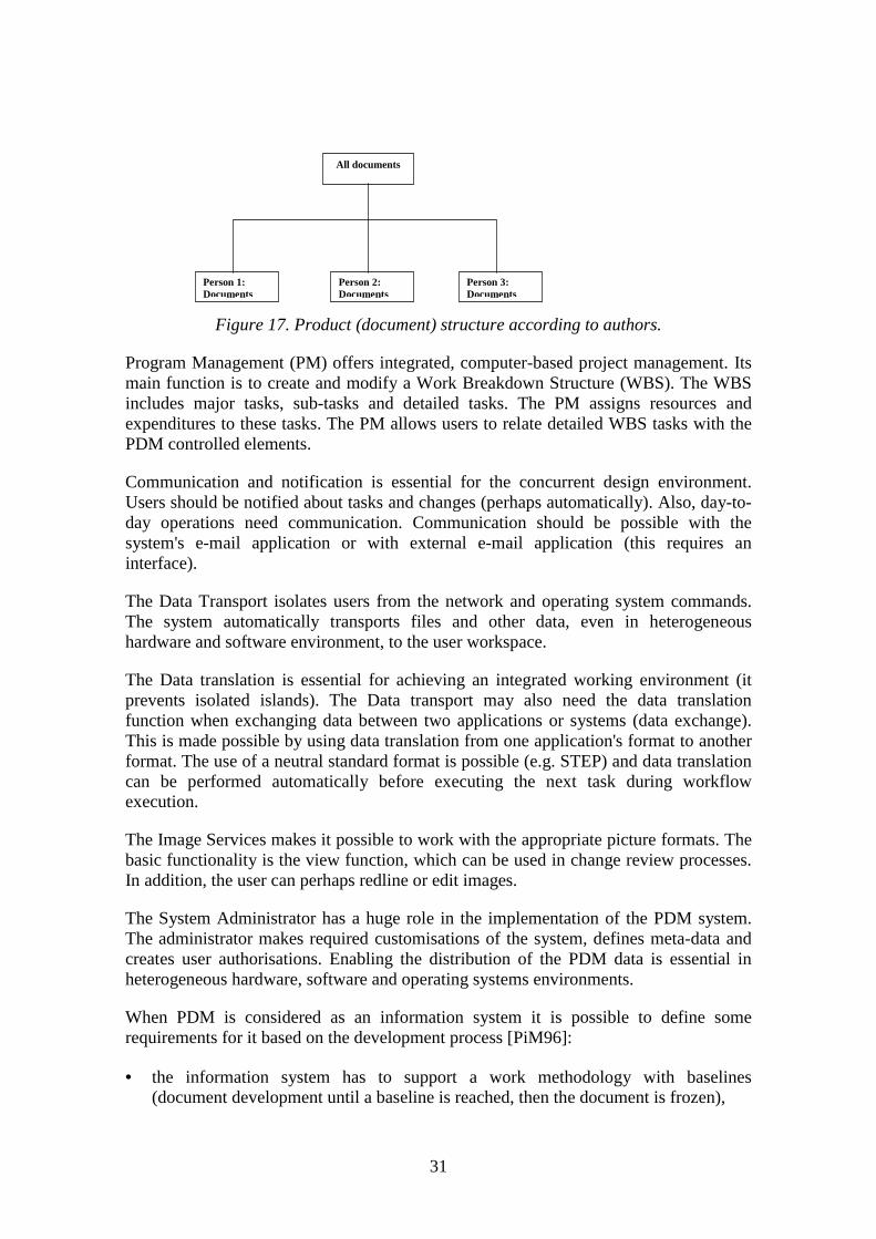
Traditional PDM systems had centralised data vault functions and change management.This centralised model no longer meets companies' requirements in the new businessenvironment. Nowadays the companies globalise functions, differentiate products andtry to focus on certain market segments. This development has created a closecollaboration with sub-contractors, suppliers, and vendors.
All this meant was that when using old PDM systems, massive centralised PDM-dataand administrative data control was necessary. Independent sub-contractors are alsoreluctant to allow other companies to control their data. PDM vendors have to adapt tothis situation and provide federated solutions where local administration is possible(Figure 18).
Figure 18. Independent organisation and centralised data management.
Many early PDM systems were developed by mechanical CAD (MCAD) vendors tohelp manage files [MaM97]. Thus, PDM systems have well-established techniques inthe field of mechanical engineering design, but other technologies have been left withminor attention [Sto99]. For example, the need for electrical CAD (ECAD) applicationsdata management has led to the creation of modules that offer some limited PDMfunctions for the certain design tool (e.g. tools frameworks can contain this kind offunctionality) [MaM97]. Nowadays the products are complex and the design combinesmany different technologies. Embedded software has particularly become an alternativeimplementation technology for electronics [Tar98, AyJ96]. One reason for this isversatility. PDM deliverers already provide some integration with the software, ECAD
L o c a ld a ta b a se
L o c a ld a ta b a se
L o c a ld a ta b a se
L o c a ld a ta b a se
L o c a ld a ta b a se
L o c a ld a ta b a se
N etw o rk

33
(electronic computer aided design) and publication tools [MaM97]. In the future, PDMsystems may also replace the lower-level frameworks and provide data managementservices directly for design tools [MaM97].
Concurrent engineering (CE) strategy allows different design-participants to workconcurrently which gives the company the possibility to decrease costs and reduce aproduct's time-to-market [Hei97]. PDM systems support CE by providing easycommunication, early access to the design data and data exchange functions.
The rapid development of Web-technology and the Internet has an effect on the PDMsystems user interfaces. Java-based user interface will replace traditional client-basedinterfaces because Java offers platform and operating systems independence (Figure19).
An ERP (Enterprise Resource Planning) system controls a company's whole productionchains operations that includes such things as contract management, production, andprocurement. Figure 3 in Chapter 2 represents manufacturing flows. The flows ofmaterial, product, customer and purchasing are under the control of ERP, and aproduct's design is under the control of PDM. However, there is some overlap betweenPDM and ERP (e.g. BOM). This overlapping causes difficulties when systems have tomaintain integrity of data. The integration of these systems creates better life-cyclemanagement of the product data.
Figure 19. Windchill-system Java-based user interface.

34
Other trends are the increasing use of object technology, project managementintegration and focused solutions. The project management integration will integrateresources (persons and costs) into the product data management. By using this feature itis possible to consider the state of the project and project documents as well as toconsider resource allocation. Focused solutions solve specific problems in particularindustries or processes [Mil99]. This specialisation allows e.g. quicker implementationand contains specialised terminology as well as discipline-specific reporting formats[Mil99].

35
4. Data exchange
Data exchange exists between tools, organisations and people (globalisation, sub-contracting). For example, an engineer creates a design and sends it to the next engineerfor modifications. The data translation may be essential, for example, because the firstengineer's design tool does not include all required features. The next engineer mayhave difficulties working with the information created by the first engineer. Thissituation arises because the data that the first engineer created can be structured andrepresented using data format which the receiver does not recognise.
Data exchange is possible, for example, via shared databases, but still the basic problemremains: how can different systems understand each other? This chapter representssome standards which can support the data exchange between systems. Section 4.1contains a general introduction to the problem. Section 4.2 presents the architecture ofthe STEP standard which is used in CAD data exchange. The section also representsPDM Schema which provides a neutral format for the product data exchange. Section4.3 presents the CDIF standard which is used for CASE data exchange. Section 4.4introduces the SGML standard which is used in document exchange.
4.1 Data formats and translators in data exchange
The different data formats are a problem when exchanging data between two systems.This problem can be solved by using translators, which translate data from one formatto another (the receiver needs to understand the sender's data format) (see datatranslation in Section 3.1). This solution is efficient if there are only a few tools whichneed data exchange. Figure 20 illustrates a situation where data exchange is neededbetween four design tools.
Figure 20. Data exchange between different design tools using translators.
Engineer 4
Engineer 1
Engineer 2
Engineer 3

36
Each design tool communicates with three other systems. In the worst case, "engineer1" requires six data translators, three for data export and three for data import. So theneed for a common exchange format is obvious in heterogeneous environments.
There are three other approaches when considering solutions for information exchange[Sää98]:
• "total software" that includes all the necessary software components to do theengineering task,
• a common communication language (tool or discipline specific), and
• a standard that aims to handle all kinds of data (e.g. STEP).
"Total software" is a good solution but is hard to implement (all users should have thesame applications). The second approach is tool or discipline specific and therefore it isnot very versatile. In an ideal situation there is no need for the native formats becauseevery application produces and reads the same standard format (regardless or the type ofthe data: text, picture, voice, etc.). The last approach aims to provide a standard for dataexchange that can handle all kinds of information relating to a product. [Sää98]
There are several standards and de facto standards for data exchange. For example, dataexchange between these tools is possible with the use of the DXF (Drawing InterchangeFormat) or IDF (Intermediate Data Format) format. DXF is AutoDesk's de factostandard. IDF provides a neutral representation for exchanging printed circuit assemblydata. This kind of data exchange is essential because of printed circuit board geometrics(keep-in, keep-out-areas, vias, board geometry), among other things. However, thisreport focuses on three standards: STEP, CDIF and SGML.

37
4.2 STEP (STandard for the Exchange of Product model data)
Nowadays, companies globalise their functions, and applications must run in differenthardware and operating system environments. Easy data transfer from one application toanother is important. The design and data modelling techniques are also in continuousevolution and therefore it is important that tools can be extended to take advantage ofnew and innovative techniques without data exchange problems.
The STEP standard's initial release was approved by the ISO-Standard (ISO 10303) in1994 [PeT98]. The basic idea of STEP is to enable organisations to share and transferproduct data between different computer systems and environments [MaM97]. Thefollowing list contains the basic components of STEP (the classification is based on theISO 10303 standard) (Figure 21) [Ind94].
Description methods
Implementation methods
Conformance testing
Integrated rescources
Application protocols
Figure 21. The basic components of STEP.
1. Description methods describe a common mechanism for the specification of data.Integrated resources and application protocols are expressed using EXPRESS, which isan object-orientated data modelling language. EXPRESS-G is a subset of EXPRESS,supporting the graphical notations of schema. The basic aspects of EXPRESS are:
• schema: a collection of related information,
• entity: a real world concept (object),
• attribute: the property for the object, and
• type: a representation of value domains (also an ordered set of values is possible).

38
The next example illustrates these aspects by using EXPRESS (Figure 22).
Figure 22. Employees' day-off information defined by EXPRESS.
2. Implementation methods include implementation techniques for the informationstructures defined in the application protocols. An ISO 10303-21 defines text encodingfor the exchanged data (Figure 23). This physical STEP file can be used to exchangedata. SDAI (Standard Data Access Interface) (ISO 10303-22) is a programminglanguage independent application programming interface for STEP data. By usingSDAI designers can access the data defined in EXPRESS.
Figure 23. ISO 10303-21 defines encoding of data when exchanging information.
3. Conformance testing provides data which is used to test the conformance of a givenimplementation.
EXPRESSDefinition
Data
Physical STEP file
ISO 10303-21
TYPE week_day = ENUMERATION OF(Monday,Tuesday,Wednesday,Thursday,Friday,Saturday,Sunday);
END_TYPE;
ENTITY Information;name : STRING;age : INTEGER;day_off : week_day;END_ENTITY;

39
4. Integrated resources contain generic and application resources. The generic resourcesare application-context-independent data constructs which constitute the minimal set ofentities (generic data structures) that are used by all application protocols (AP). Theapplication resources can reference the generic resources and add other resourceconstructs for use by a group of similar applications [Ind94].
5. Application Protocols (AP) interpret integrated resources to meet the productinformation requirements of specific applications [Ind94]. So, integrated resources arenot intended to be implemented directly. The interpretation is achieved by selectingappropriate resource constructs and refining their meaning by specifying anyappropriate constraints, relationships, and attributes [Ind94]. So AP represents the datafor the specific product or industrial needs. We can consider AP as a selective filter. Itspecifies those generic concepts from the Integrated Resources that are needed for aparticular purpose and defines the meaning of these generic concepts in the specificcontext of the application. The STEP data file used for data exchange, defined in Part21, is then defined by the AP and can be implemented in the computer software so thatthe use of Standard becomes transparent to the user. There are APs for example forelectronic design and installation (ISO 10303-212).
STEP supports four levels of data sharing and transfer [MaM97]:
1. File exchange: data is exchanged between systems or applications using STEPexchange files (physical STEP file).
2. Working form exchange: data is shared with the use of a working form, which isnormally a common file shared by the systems.
3. Shared database: data in STEP format is available in a shared data environment(controlled by DBMS (Database Management System)). The database providesconcurrent access to a STEP database from multiple applications.
4. Knowledge base: data is shared within a Knowledgebase Management Systempromising to provide advanced tools for virtual and distributed enterprises (e.g. expertsystems).
PDM Schema is a reference information model for a central, common subset of the databeing managed within a PDM system. It represents a set of common requirements anddata structures from a range of STEP Application Protocols, all generally within thedomains of design and development of discrete electro/mechanical parts and assemblies(Figure 24). [Usa99]

40
Figure 24. PDM Schema as a subset of four application protocols [Usa99].
The PDM Schema is a subset of the PDM related application protocols [Usa99]:
• AP203: Configuration Controlled Design,
• AP212: Electrotechnical Design and Installation,
• AP214: Automotive Design,
• AP232: Technical Data Packaging.
It contains the following modular semantic units of functionality [Usa99]:
• Part Identification,
• Part Classification,
• Part Properties,
• Part Structures and Relationships,
• Document Identification,
• Document Classification,
• Document and File Properties,
• Document Structure and Relationships,
• External Files,
A P 2 1 4 A P 2 1 2
A P 2 3 2A P 2 0 3
P D MS c h e m a

41
• Document and file association to product data,
• Alias identification,
• Authorisation,
• Configuration and Effectivity information,
• Work Management data.
The next example (Figure 25) represents how a product structure is defined with the useof PDM Schema (STEP file example). A-1 is an assembly and P-1 and P-2 are theproduct's components.
Figure 25. A simple product structure.
The example contains one assembly and each component has only one version and life-cycle view. This means that there is only one configuration. If there were severalversions from the components, the total amount of configurations would increase.
ISO 10303-21 describes physical text encoding for the STEP exchange file. The nextSTEP file example represents previous assembly (only configuration information)(Figure 26).
A - 1
P - 1
P - 2

42
Figure 26. Part of the STEP exchange file, which represents assembly informationpresented in Figure 25.
However, the PDM Schema is not a specification for the complete PDM systemfunctionality.
To conclude, STEP contains product and industrial specific Application Protocols (itspecifies the representation of product information) which is based on a commonfoundation (generic resources). The standard is not easy to adopt because not all PDMsystems support STEP. The solution for these problems can be the PDM Schema, whichis a subset of PDM-related application protocols.
4.3 CDIF (Case Data Interchange Format)
The Electronic Information Group (EIG), established in 1993, consists of five divisions:CDIF, DAD (Design Automation Division), EDIF (Electronic Design InterchangeFormat), EIDX (Electronics Industry Data Exchange) and IAD (Industrial AutomationDivision). Each of these divisions cover a different domain of information exchangesolutions for the electronics industry.
CDIF is a family of standards, which can be used to exchange data between two CASEtools (Computer Aided Software Engineering) (Figure 27) [CDI99a]. The goal of thestandards is to allow modelling tools to understand each other. The CDIF focuses on thedescription of the information to be transferred, not on data management. It defines theinformation content, the transfer mechanism and interfaces, but not implementations.
.../* STEP excahange file format that contains assembly information.
#10 = APPLICATION_CONTEXT('');#20 = PRODUCT_CONTEXT('', #10, '');#30 = APPLICATION_PROTOCOL_DEFINITION('version 1.1', 'pdm_schema', 1998, #10);
/* assembly and part instances#40 = PRODUCT('A-1','A cube with a dowel', '', (#20));#50 = PRODUCT('P-1','Cube', '', (#20));#60 = PRODUCT('P-2','Dowel', '', (#20));
/* life-cycle instance (available lifecycles)#70 = PRODUCT_DEFINITION_CONTEXT('part definition', #10, 'design');
/* version instances (no multiple versions)#80 = PRODUCT_DEFINITION_FORMATION('1A-1', '', #40);#90 = PRODUCT_DEFINITION_FORMATION('1P-1', '', #50);#100 = PRODUCT_DEFINITION_FORMATION('1P-2', '', #60);
/* view instances (one view for each component)#110 = PRODUCT_DEFINITION('Assembly view', '', #80, #70);#120 = PRODUCT_DEFINITION('Cube view', '', #90, #70);#130 = PRODUCT_DEFINITION('Dowel view', '', #100, #70);
/* instances that define the product structure#140 = NEXT_ASSEMBLY_USAGE _OCCURRENCE('CP-1', 'Assembly instance of cube', 'Cube', #110, #120, $);#150 = NEXT_ASSEMBLY_USAGE _OCCURRENCE('CP-2', 'Assembly instance of dowel', 'Dovel', #110, #130, $);...

43
Figure 27. CDIF transfer [CDI99a].
Information exchange between design tools is important because companies use severaldesign tools with different capabilities, and information consistency between all thesetools is essential. The CDIF defines layers of information (meta-layers) (Figure 28)[CDI99a].
User Data contains physical information. This data is not relevant for the CDIF standard(CASE tools produce model-data). The Layer Model describes this User Data. Forexample, the model can explain that a system includes Order data and Customer data(Order Processing System), and according to this model one customer can have one ormultiple orders (Figure 29). Layer User Data then allows the description of informationaccording to these rules. In data exchange the model-data is exchanged between CASEtools.
Figure 28. Layers of information [CDI99a].
Figure 29. Data model [CDI99a].
Exporting tool Importing toolCDIFtransfer
O rder Custom er1:N
1:1
Meta-Meta-Model
Model
Meta-Model
User Data
The upper level defines the rules forthe lower level from which it isabstracted

44
The Meta-Model defines the standard structures and data which are allowed when datamodels are described. A Meta-Meta-Model defines meta-data structures for the Meta-Model. The Meta-Meta-Model is defined as a standard EIA/IS-107. So, the Meta-Meta-Model defines rules for the Meta-Model which in turn defines rules for the Model.
CDIF separates the definition of what information is transferred from the definition oftransfer format (Figure 30) [CDI99a].
Figure 30. Architecture of CDIF [CDI99a].
The Integrated Meta-Model is a standardised meta-model and it attempts to providedefinitions for all the information of the CASE tool. This is not easy to define becauseSoftware Engineering is continually developing. Therefore, the Integrated Meta-Modelprovides definitions for small areas called "subject areas". Each subject area is aseparate standard (e.g. Data Flow Model Subject Area / EIA/IS-115). If these commonareas don't support a certain information definition need, it is possible to extend thesedefinitions. These extensions must be well defined. [CDI99a]
When a model is transferred from one system to another, both the systems must have acomplete Meta-Meta-model and Meta-model. In addition, a complete definition of thetransfer format is required. A CDIF transfer contains a Transfer Envelope and TransferContents (Figure 31). The Transfer Envelope defines a CDIF signature, syntax, and anencoding. The signature identifies the transfer as a CDIF transfer. Syntax and encodingthat will be used in the transfer is identified by Syntax Identifier and EncodingIdentifier. [CDI99b]
M eta-M eta -M od el
T ransferF orm at
In tegratedM eta-M od el

45
Figure 31. CDIF Transfer [CDI99b].
Transfer Contents contains a Header, a Meta-Model and a Model. The Header Section isnot mandatory. It can contain information about the transfer (e.g. name and version ofexporting tool, publisher, date and time). The Meta-Model section defines the subjectareas and the Meta-model extensions that are used in transfer. This section contains areference to the subject area (defines which subject area is used), and the extensions thatextend the information model (non-standardised definitions). The Model Sectioncontains instances of meta-entities and meta-relationships (model data). [CDI99b]
When we consider the CDIF and the STEP, some similarities can be found. Both ofthem have a layered modelling framework. The STEP has process and data models andthe CDIF model levels. They both organise transfer standards into the domains. TheSTEP has the Application Protocols and the CDIF the subject areas. However, the STEPcovers almost all product definition aspects when the CDIF focuses on informationtechnology systems. [Joh99]
4.4 SGML (Standard Generalized Markup Language)
Documents are produced by using different applications (different data formats) andplatforms. Different data formats are a problem when exchanging data in thisheterogeneous environment. So, a standard for representation of document structure isessential. The SGML standard was released in 1986 (ISO 8879). The basic idea of thisstandard is to achieve software and platform autonomy when storing text documents. Italso distinguishes document content from its styling. By using SGML it is possible tocreate descriptions for logical structures of different kinds of documents (meta-language). The SGML does not interfere with the way in which the applicationsrepresent documents.
An SGML document consists of an SGML Declaration, Document Type Definition(DTD), and the instance of the document. The SGML Declaration gives the precisedetails of how SGML is applied to a certain document as well as describing a characterset (ASCII, EBCDIC, etc) and special characters (e.g. < and >). The DTD defines thestructure of a document. All documents must have DTD. It can be stored internally in
T ra n s fe r E n v e lo p e
T r a n sf er C o n te n ts
C D IF S ig n a tu re
S y n ta x I d en t i f ie r
E n co d in g Id e n ti f ie r
H e a d er S ec t io n
M e ta-M o d e l S e c tio n
M o d e l S e c tio n

46
the document, or externally (the document contains it or has a reference to the filewhich contains DTD). The document instance is the document itself. Its contents havebeen marked by using DTD. [Her94]
A company’s design process produces the product data and technical documentation.The Commission of the European Communities partly the funded DOCSTEP projectwhich tries to integrate product data and product documentation. The product data canbe represented by using the STEP standard and the technical documentation by usingSGML. [ElK97]
The structured documents can provide better retrieval when the user searches forinformation. It is possible to search and parse information from documents according tothe structures, and represent information found using an appropriate format (e.g. searchfrom SGML documents and represent found information to the user by using an HTML(HyperText Markup Language)). HTML is an SGML-conformant markup language[Mau96]. It defines a document's layout but it does not define what kind of informationit contains [Haro98]. XML (Extensible Markup Language), which is actually a subset ofthe SGML, allows the definition of the document’s content [Haro98].

47
5. Requirements of design data management
This chapter defines the requirements for the embedded product's design datamanagement. Section 5.1 contains a short introduction to the business and designenvironment. Section 5.2 considers requirements in an embedded product's design.Section 5.3 collects the requirements from the previous consideration and presents themin table format. This framework will be used when analysing different commercialsolutions for the design data management in Chapter 7.
5.1 Introduction
New products have become complex and their design processes produce more and moredata. Customers require more customised products and better quality. In addition, thedesign process needs specialists from many disciplines. Companies also focus on theircore know-how and hive off other functions to subcontractors.
Companies have to globalise design and manufacturing, and operate without therestrictions of physical distance or time [TaA99]. This globalisation of design is called"global design", which includes spatial and time globalisation [TaA99]. Spatialglobalisation contains design co-operation and the time globalisation reuses past designsand accumulates design expertise [TaA99]. This development increases externalcommunication and requires efficient data exchange. Also the integrity of theinformation is essential when a company operates in the global design environment. Inaddition, in large organisations, terminology can differ between departments as well asbetween computer systems, which complicates communication [SvM99].
Mass customisation means the customisation of products and services for individualcustomers at a mass production price. This approach allows the company to meetdemanding customers’ needs [Soi97]. The basic idea is that the product is customisedwhen it is sold. The customer can, for example, interactively define what kind ofproducts s/he wants. This kind of approach needs modularity and product variationmanagement [Soi97]. In this case, information about the exact configuration containingdesign data is essential for good maintenance (what kind of product the customer hasbought and what kind of design documents relate to the certain delivery).
5.2 Requirements for the embedded product's design datamanagement
According the previous analysis in this report it is possible to define a requirement forthe enterprise-level design data management of a multi-technological product:
A design data management system of enterprise which operates in a global designenvironment should be able to collect, save, provide access and manage all the (useful)design-related information of a multi-technology product, distribute this informationand also support a company's working methods during a product's life-cycle.

48
This definition includes the following main parts:
• data management,
• process and life-cycle management,
• data capture & distribution, and
• support for working methods.
The next sections consider each of these parts. This classification is not strict, forexample during the change process version management and product structuremanagement is required. So, these parts support each other.
5.2.1 Data Management
Data management should provide data vault, product structure management,classification, retrieval and document management. These functions are defined insections 2.5 and 3.1.
The configuration of a multi-technological product contains components and sub-assemblies implemented by using different technologies. The information system shouldbe able to construct a description of this multi-technological configuration includingembedded software. Nowadays, manufacturers fail to manage software as an integralpart of a whole product's design [Mil98].
Embedded products can have the same mechanical configuration but differences areconstructed by using embedded software [Mil98]. So it is possible to carry out customerspecific features by using embedded software [Sep97]. An embedded product's structurecan also contain e.g. HW/SW interface documents and other non-hierarchical relations,which requires the management of items relationships [Tar98].
The design of a software system needs tools which build software products (softwareprogram build using the right modules and configurations). These SW configurationsare based on certain baselines and tracking this information is needed. For example,maintenance needs to know which item versions have been used in a certain productrelease. Information about customers is also required (what kind of configuration hassomeone bought) [AuT96]. All parameters and flags used in the software build shouldalso be saved [Leb94]. The version control needs to manage version history (all designdocuments) and to allow the tracking of previous versions [Leb94].
As mentioned in Section 2.3.1, parallel modifications are needed in software design, andtherefore the system should allow multiple copies from one item and control how tomerge these items when checking in (Figure 32). [Wil97]

49
Figure 32. Multiple copies, parallel development and merging.
Engineering changes were considered in Section 2.2. Software changes differ fromhardware changes [Ber92]. Hardware is a set of physical parts but software is intangible[Ber92]. If you want to examine the reason for the error you have to sometime examineboth the software and the hardware [Ber92]. By using impact analysis it is possible torecognise the impact of changes when e.g. HW change is performed [Tar98]. Thisrequires the definition of relationships between components.
5.2.2 Process and life-cycle management
Process (see Section 3.1) and life-cycle management has a strong connection with theproduction and use of data. Companies perform duties according to certain processes.When they are performing a certain task they may need to link some supportinformation to the task, or the purpose of the task may be to produce information (e.g.drawing). So this function links design documents to the company's processes.
The importance of software has rapidly increased and this development needs processand life-cycle automation which keeps track of e.g. who is working on what, whichmodule a designer is responsible for, what kind of tests each module has passed, etc[Wil97]. Life-cycle management saves information about these objects (designs,documents, configurations, etc) and controls how these objects mature during aproduct's design process.
In addition, production process planning has to be a part of a whole product'sdevelopment when considering electronic products [Kiv98]. The designer needs tounderstand how different materials match from a physical and chemical point of viewwhen manufacturing the product [Kiv98].
5
4
2
1
3
2
1
6
M a in b ra n c h
S u b - b ra n c h

50
5.2.3 Data capture & distribution
The development of an embedded product contains several discipline-specific designprocesses (see Section 2.3) (Figure 33) [Rah99]. Communication and co-developmenttechnologies between these processes are important [Hei97]. The system should provideinformation for global distribution when necessary. It should also allow users to viewand comment on design documents without using native design tools.
Figure 33. Co-operation and communication between technical design processes.
The integration of a design tool and a data management system is essential in enterpriselevel data management. Data management systems do not create new productinformation, they only help to control it. The design process of multi-technologyproducts include multiple design tools and design systems (these tools and systemscreate product information). Within a design team the data is usually easier to manage(design team data management solutions) but these kinds of solutions do not solve theenterprise level data management problems. These solutions only create "automatedislands" inside which the data management is well realised, but information exchangebetween the teams remains difficult. Anyway, all this information should be visible inthe organisation, which requires tool integration and data exchange.
Fast and accurate data exchange during a product's life-cycle is essential to the companybecause transfer doesn't refine exchanged information. The data being moved betweentwo systems must be translated from one application's format to the other’s, or theymust use a standard format common for both parties [MaM97]. Different users alsoneed different kinds of information and they also have requirements of how theinformation is represented.
SystemDesign
Software design
Electronics design
Mechanical design
Systemintegration
test
Other disciplines
Continued
systems
engineeringinvolvem
ent

51
The International PDM Users Group (IPDMUG) represents requirements for theintegration of PDM and ECAD (data-objects and functions). Data-objects required areECAD design database, engineering BOM file and viewable images. The functionscontain e.g. Check-in/out, copy out, and data compaction functions. In addition,IPDMUG defines some objects and functions, which provide additional value to theuser. IPDMUG includes additional features for the data-objects and a whole new object-type. First, design database should include a simulation database. Second, the BOMshould also contain component substitution capability. Third, images should containmanufacturing and assembly notes. Finally, one object-type was added: derived files(like board fabrication files). [Ele99]
The functions which provide the additional value to the user are: [Ele99]
• integration with component management system,
• integration with the ERP system, and
• process (workflow) integration between PDM and ECAD design tools.
5.2.4 Support for working methods
Different working methods can provide a company with better time-to-market, amongother things. These methods may also have requirements for the company's informationsystem. This report focuses on two methods (or principles): concurrent engineering andknowledge management. Actually CE is a collection of several methods, tools andhuman factors [Hei97], but in this report it is referred to as a working method orprinciple. The rest of this section considers both principles. These principles are usefulfor all kinds of production (not only for the production of an embedded product).
The information system should provide tools and features which support a company'sworking methods. For example, nowadays, enterprise level PDM systems (EPDM)provide features that support concurrency during a product's design. However, thesefeatures don't automatically bring the Concurrent Engineering (CE) principles into thecompany. CE needs commitment and a strategy, and the information systems onlyprovide some tools for it. Section 2.4 offered a quick glance at the CE.
PDM systems are useful for concurrent engineering because they offer product datathroughout a company during the product's life-cycle. During a design project, datashould be represented along with the product data (project and product documentation).Then it is easier to consider the design project's state and documents. Also theintegration of development teams is important when one considers concurrentengineering. The integration mechanism can be described with five dimensionsaccording to Figure 34. The sequential work methodology is on the left hand side andconcurrent on the right. [PiM96]

52
Figure 34. Dimensions of the integration mechanism [PiM96].
The concurrency considers how much overlapping there is between design phases. Thisoverlapping between stages requires good communication and good data exchange. Themedia richness means the "quality" of the contact between designers. It could be, forexample, just document exchange or more physical contact (video, audio) betweendesigners. The information transmission considers how the documents are transmitted tothe system. The fragmented approach transfers a document to the system directly whenthe document is ready for it. The communication direction should be bilateral, whichsupports feedback and comments. The information release has an effect on concurrentengineering. The early release supports concurrent work by providing the early visibilityof information (preliminary information can have e.g. "draft" status). [PiM96]
The PDM should also automate certain non-value adding processes like documentreviews. This means, for example, automatic notification and automatic workflowprogress after specific tasks. [PiM96]
PDM systems also provide features that support the management of knowledge in acompany. Knowledge includes information, experience and skills. KnowledgeManagement is complex, and it contains [Lah98]:
• a network containing people and machines,
• a recognition of what the organisation knows and what it should know, and
• the creation of means that distribute this information.
Design knowledge contains all the information which is needed to design a product[Kor96]. This information contains e.g. drawings, specifications and all decisions duringthe design process. This knowledge can be captured for example in a design review
S e q u e n tia lS e q u e n tia l
D o cu m en tsD o cu m en ts
B a tch t ra n sm i ss io nB a tch t ra n sm i ss io n
U n ila tera lU n ila tera l
L a te re lea seL a te re lea se
S t a g e o v er la p p in gS t a g e o v er la p p in g
F a ce - to -fa ceF a ce - to -fa ce
F r a g m en tedF r a g m en ted
B ila te r a lB ila te r a l
E a r ly r e le a seE a r ly r e le a se
C o nc u r r e n c y
C o m m u n ic a tio n d i r e c ti o n
M e d i a r ic hn e s s
In fo r m a ti o n tr a n sm i s s i o n
In fo r m a ti o n r e le a se

53
(decisions and comments are documented) and these documented decisions should beattached to the appropriate product structure or component (design and project dataintegration). The design knowledge can be divided into two main parts: product-relatedknowledge and design related knowledge [Kor96]. Product related knowledge is adesigner's description of the product. The design-related knowledge contains all thedesign decisions, the reasons for these decisions, and the design history (e.g. partitions,see Section 2.3.3). A data management system should be able to collect, store, and sharethis information.
5.3 Requirements for enterprise-level design data management
These requirements have been collected from the previous analysis. When using theword "product", we mean especially an embedded product. Table 1 containsrequirements (or features) based on product development, PDM classification, dataexchange, and embedded product design consideration.

54
Table 1. Classification for design data management of an embedded product.
Data Management: How to manage all the data?
Data vault and documentmanagement
-support for all data types-user definitions, access and security functions (administrator)-meta-data and files or links to files (also external repositories but central management)-check-in / check-out-functions-document version management (also possibility to parallel development)
Product structure management-product structure creation -multi-technology product (include SW, HW, and other modules) -structure from workgroup-tool or design-tool -also manual creation and modification-configuration creation and modifications-configurations & customers management (what kind of design documents relate to a certain delivery)-also non-hierarchical relations-supports document incorporation to the structure-user-defined views to structure (as-manufactured, as-planned)-graphical view, search, navigation-automatic bill of material (BOM) creation-possibility to define substitute components and reconstruct past configurations-software build
Classification and retrieval-part (component) management, retrieval, reuse, and classification (including suppliers and other information)-attribute (meta-data) definition to parts, assemblies, documents, and relations-possibility to search documents according to different attributes and content-information representation according to classification rules (e.g. part families)
Process and life-cyclemanagement:
How to connect data management to a company's processes and how to managethese processes?
Process management-possibility to define and modify processes (like engineering change and approval processes)-project management, including resources and expenditures (or integration with external managementapplication)-support for nested processes, branching, merging, notification-process state monitoring-incorporation of documents as well as other supporting information (work packets) into processes and tasksand their review-production process plan and incorporation of information to phases
Life-cycle management-possibility to define life-cycle for objects (product, design, documents, components) and rules for transitions-possibility to track design and document history during design (documents, who modified and when, status,etc)-access control according to life-cycle state
Data capture &distribution:
How to collect and distribute all information?
Data exchange-data translation (automatic / manual)-support for neutral exchange formats-tool (application) integration (all appropriate tools e.g. MCAD, ECAD, ERP, Component Managementsystem)
Image services-possibility to view design documents (all appropriate formats and use of neutral formats such as PDF)-document redline and comment capability
Global access, notification, andcommunication
-possibility of global access (e.g. Web, traditional client)-possibility to communicate (e.g. use of internal or external e-mail system)-automatic notification (e.g. when there is a new document in system, or during processes)
Methods: How can a system support the working methods of a company?
Design knowledge management-system should allow an organisation to collect, save and share all design-related knowledge
Concurrent engineering-possibility to represent project data with the product data-support for the stage overlapping (e.g. parallel modifications)-fast and early data release-integration of the development teams-possibility to automate processes (e.g. automatic notification and progress, data translation between phases)

55
The data management, process and life-cycle management, and capture & distributionshould support a company's working methods (Figure 35).
Figure 35. Features and company's working methods.
The working methods of the company aim to support business requirements (e.g.decrease time-to-market). So, the data management, process and life-cycle managementand data capture and distribution don't solve the company's problems but they dointroduce features which can support working methods or principles.
Data management introduces basic features which are used by the other parts. Processesand life-cycle management connects data management with a company’s processes.Data capture and distribution makes it possible to collect data, communicate with designsystems, and distribute data in the correct form to all parties.
When a company considers PDM implementation, it is essential that the system meetsthe company's needs and resources. Companies' requirements vary and therefore onecompany can choose a simple solution (e.g. central data vault with check-in and check-out functions) and another a complex solution like the PDM system which offers manydesign tools features like the creation of BOM and the possibility to view designdocuments. So, we have to consider what kind of functions we want under themanagement system when considering PDM implementation.
Da t am a n a ge m e nt
Dat a c a p t u re &d i s t r i bu t i o n
Proc e ss a ndlife c yc le
m a na ge m e nt
Ite m s should support c om pany’s w ork ing m e thods

56
6. Design data management levels
It is a fact that design data management occurs at different levels (Figure 36). Twokinds of PDM implementations can be found: the first focuses on the enterprise level(EPDM, Enterprise Product Data Management) and the second on the department orworkgroup level (Team-PDM) [MaM97]. However, design tools also have documentmanagement capabilities, mainly concerning an individual designer. So there are threedesign data management levels and the company can have systems for every level.
Figure 36. Levels of the design data management.
This classification is not always clear because the differences between systems aredifficult to define. The PDM vendors sometimes use the same terminology to describedifferent capabilities, and PDM products reflect the vendor's different interests,backgrounds, and technologies [MaM97]. This report considers levels of design datamanagement. Section 6.1 introduces tool-level design data management. Section 6.2contains a consideration of team-level design data management which can be utilisedwhen a company is planning to introduce an enterprise-level design data managementsystem. Section 6.3 contains a consideration of enterprise-level design datamanagement.
6.1 The design data management features of design tools
The design tools offer some data management features and PDM modules forcontrolling design data [MaM97]. In the electronics industry these design tools can beoffice applications, mechanical CAD, electrical CAD, and software tools, or other
EPDM
Designtool
Designtool
Designtool
Designtool
Designtool
Designtool
Team-level datamanagement
Enterprise-leveldata management
Design tool level
Team /Management Team /
Management

57
technology-specific tools. This section focuses on the design tools data managementfeatures, usually used by a single designer. The following examples represent documentmanagement possibilities referring to certain applications:
1. AutoCAD
Autodesk is a software company providing design solutions. Their design solutionnamed AutoCAD is a mechanical design tool (MCAD). This solution also offers somedesign data management features to designers (AutoCAD LT contains a subset of thesame features).
AutoCAD allows designers to create reusable design components using blocks andreference drawings. A block contains e.g. one part (drawing) or logo. These blocks canbe collected in a block library. It is possible to manage block-libraries with the use ofutility programs. The block can also contain attributes which allow designers to definealternative alphanumeric information to blocks. The AutoCAD reference drawingsystem can be used to produce the reference drawings (Figure 37). When using areference drawing system, the assembly drawing only contains pictures from theexternal drawings. Reference drawing is always updated when an user opens it. Thisfeature assures that the assembly is always updated after part modification. [Sal97]
Figure 37. Assembly drawing contains references to several external drawings.
It is also recommended that all related drawings should be saved in the same projectfolder. Network technology also allows the use of shared network folders, and dataexchange with other design system is possible with the use of e.g. DXF de factostandard format. [Sal97]
I m ag e D o c u m en t I m ag e D o c u m en t
I m ag e D o c u m en t
I m ag e D o c u m en t
A s se m b lyd r a w in g
L in k s to e x te r n a l d ra w in g s( a s s e m b ly d ra w in g is u p d a te dw h e n i t i s o p e n e d )

58
2. Cadence EDA (Electronic Design Automation) design tools:
Cadence Design Systems offer an electronics design environment containingapplications for electronics design. Cadence's schematic design tool Concept HDLsupports top-down design, which allows the user to define system functions and levelsof hierarchy. Cadence Hierarchy Manager (part of Concept HDL) allows the designer tochoose a symbol to depict modules and their relationships. By using Cadence's layoutdesign tool it is possible to read and save the information in DXF format and IDFformat. This information translation is important when exchanging information withMCAD (Figure 38). It is also possible to convert the design to a producer's machine toolformat (e.g. Gerber). So the design file is directly readable for the machine tool (e.g. adrilling machine).
Figure 38. An example of the design data exchange between MCAD and ECAD.
6.2 Team-level design data management
MCAD, ECAD and software application vendors have created modules which provide alimited team-level PDM functionality [MaM97]. These tools focus on their ownapplications' document and design process management. The CAD frameworks are thecommon user interfaces for the co-operative use of tools [MaM97]. The frameworkguides users through the proper order of steps, applications and data conversations[MaM97]. In this report these frameworks are one type of team-level managementsystems.
MCAD ECAD
File inIDF -format
File inIDF -format
Geometric information
Design to the 3D-modelling

59
The surveys show that electronics engineers can spend 25% or more time searchingdrawings, archiving new data and checking to see which file is current. This is thereason why electronics engineers also need PDM functionality. It is estimated that lessthan 20% of electronic engineers are using any kind of PDM tools. [Sto99]
This paragraph provides one viewpoint to integration. The team or workgroup-leveldesign management systems are of great importance to enterprise-level datamanagement when using EDA tools. The user-level EDA design tools and enterprise-level data management systems are very dissimilar, which makes it difficult to integratedesign tools with the PDM systems. One solution to this is the use of a team-leveldesign management tool (Figure 39). This team-level tool provides access (for the PDMsystem) to team level data and it also manages the design process. [Cut98]
Figure 39. Team-level design management [Cut98].
This approach can also be suitable for other disciplines' design tools integration with theEPDM systems [MaM97]. The EPDM systems use discipline-specific frameworks tocontrol a whole product's data [MaM97]. For example, it is possible to connect amechanical design group to the Winchill EPDM system by using Windchill's gateway tothe Pro/INTRALINK application (a team-level data management system).
Software has become an important part of embedded products. The management ofembedded software is an integral part of product development. One of the simplest waysto carry out software assembly is the use of a make-tool [AuT96]. All relations aredescribed in a makefile, which is a source file for the make program. The execution ofthe make program compiles and links a code using appropriate modules.
Software development tool vendors also offer some limited PDM functionality[MaM97]. These team-level management tools for software configuration management(SCM) include for example version and change control as well as program assemblytools [Tar98]. Bell and Evans define configuration management as follows [BeE89]:
The process of identifying and defining the deliverable system items, and controlling therelease and change of these items throughout the system life-cycle.
E D A to o l
E n te rp r i s eP D M
T e a m -le v e ld e s ig n
m a n a g e m e n t
Enterprise
Team
Individual
Tool oriented Multi-discipline

60
The EPDM system integration with software tools can be done using local datamanagers (like EPDM and MCAD integration) [Mil98]. This means the use of asoftware configuration management tool as a team level design management tool, whichconnects the system to the enterprise level.
The implementation of a PDM system can be focused on a single department or a teaminstead of at enterprise level [MaM97]. Within a team the data is usually easier tomanage (team-level solutions) but these kinds of solutions do not solve the enterpriselevel data management problems. These solutions only create "automated islands"inside which the data management is well realised, but the information exchangebetween the teams remains difficult [PiM97].
6.3 Enterprise level design data management
The next consideration includes issues with regards to the enterprise level managementof design data. These systems are usually solutions which manage all the data of theenterprise. The EPDM systems cover all product-related data and these solutions areone possibility for enterprise-wide data management. The utilisation of existing systemsis nowadays essential in order to achieve enterprise-level data management (e.g. team-level design management systems handle many data management tasks and all changesare reported to the enterprise-level system). In the future it is possible that PDM systemswill replace all these existing lower level systems (e.g. frameworks) [MaM97].
International standards (e.g. ISO 9000) require the documentation of a company'sprocesses and evidence that the processes have been executed according to thisdocumentation. PDM systems can support the standards by forcing the company tooperate within these parameters. [HaH95]
When one considers design system integration and the enterprise-wide design datamanagement of an embedded product's design it is important to collect the wholeproduct's documentation under a single management system. The products contain sub-assemblies and modules. Therefore, design data management should link all designdocuments to the correct structure of the product. The EPDM systems interface withdiscipline-specific tools and frameworks to incorporate them to the enterprise level datamanagement [MaM97]. This creates a "virtual" product structure, which means that theproduct structure contains sub-structures from several design systems (e.g. mechanicaland electronics modules). Nowadays, EPDM vendors offer limited interfaces to ECADframeworks but there are only a few interfaces to the CASE tools [Mil98]. So,companies can have a certain SCM system for the embedded software management andthe PDM system for mechanical and electronics information management. However, theembedded software should also be managed under the enterprise's PDM system (thewhole product's configuration management). The next figure illustrates a solution wherean archive contains a product structure and the electronics and software engineeringdata are managed by using technology-specific systems (Figure 40) [PiM97]. Themechanics engineering data is managed by using the enterprise level PDM system.

61
Figure 40. The connection between EPDM and different design teams [PiM97].
Design teams need to exchange information and to be integrated with the PDM system.The application integration with PDM provides access to the functional capabilities andthe database of the PDM system. CimData divides application integration into threelevels; encapsulation, interface, and integration. Encapsulation is the simplest way tocarry out integration. It provides the possibility to the PDM system to launchapplication, but data does not dynamically flow between the PDM system and anapplication. The interface means middle level integration where an application's menumay contain direct calls to the PDM functions (e.g. check-in and check-out). Theintegration makes the application and PDM system look like they are the sameprograms. Menus contain direct calls to the PDM functions and all types of data thatneeds to be shared are common for both the systems. [MaM97]
When considering ECAD and PDM integration, the International PDM Users Group(IPDMUG) represents three kinds of integration (like CimData): simple integration, offthe self integration, and full custom integration. Simple integration may need manualsteps when exporting data to the PDM system. The second integration type providessome direct calls to the PDM functions (e.g. check-in and check-out functions). Thethird integration type means tight integration and it is usually tailored to specificprocesses. [Ele99]
IPDMUG represents four techniques to integrate two systems. These techniques mainlydeal with PDM and ERP systems integration but can also be used in other kinds ofintegration (e.g. CAD and PDM). The techniques are: [ERP99]
A r c h iv e
E P D M
P D M
E C A D
S C M
S W M C A D

62
1. People and paper:
Integration is accomplished at most manufacturing companies by using this technique.In this case the people use paper, meetings, manual data entry, and manual data re-entry.This is slow and error prone but reasonable if integration with other techniques is tooexpensive.
2. File transfer:
This technique automates the extraction, storage, and loading of data via files. Oneadvantage is that this approach isolates systems, which is important when systems areupdated. This technique also usually involves minimal changes to the businessprocesses. One possibility to implement this is to use standard formats like STEP. If acompany builds its own proprietary set of formats and therefore moves away fromstandard data export, it is possible that the number of data formats increases. This kindof system can be difficult to maintain.
3. API (Application Programming Interface):
This technique uses custom code to link both systems’ application programminginterfaces together. These programs allow real-time access to the other systems andprovide tighter functional integration. However, this technique is complex and requiressupport and maintenance. One possibility which provides simplified connection isaccess to another system's underlying database by using database vendor commands. Inany case, this method is quite similar to the file transfer technique.
4. Interfaces based on distributed objects:
Object technology makes it possible to divide large systems into smaller ones. Thesedistributed objects provide the means for dynamically changing the servers that clientsuse without them realising it. For example, CORBA (Common Object Request BrokerArchitecture) supports distributed objects. It is a protocol to extend object technologyacross multiple systems.
Data exchange and integration with other applications is possible e.g. by using STEP(Figure 41) [Har98].

63
Figure 41. Application integration with STEP [Har98, p. 17].
The interaction between the PDM system and the applications that create and changeproduct data using STEP provides application independence for data. The STEPstandard allows an organisation to use a central, neutral STEP database, andapplications can use this data via interfaces. So all applications that use SDAI(application programming interface to STEP data) are able to communicate with allother compatible applications. [Har98]
STEP-conforming PDM system
SDAI SDAISDAISDAI
Logical STEP database
PDM application O ffice application CAD application O ther applications

64
7. System review
This section introduces three PDM systems. It also presents how these systems meet thedesign data management requirements defined in Chapter 4. The PDM systems whichare presented are:
• Windchill (Section 7.1),
• Metaphase (Section 7.2), and
• PVCS Dimensions (Section 7.3).
All these systems are enterprise-level management systems which support multiplesites. This report does not contain system comparison because different systems reflectvendors’ different interests and backgrounds. However, Section 7.5 containsobservations about this review.
7.1 Windchill EPDM system
Windchill EPDM system, provided by the Parametric Technology Corporation, is anenterprise-level data management system for the management of product life-cycle. TheWindchill's first version was announced in July 1998. An interesting feature of thisproduct is the use of Web technology instead of traditional client-server technology.Windchill provides a completely CAD-neutral environment and an integrated suite ofapplications for the management of all phases in the product's life-cycle. This reportrepresents the features of Version 3. Version 4 was announced in autumn 1999 andprovides more functionality. This information is based on interviews and experimentsprovided by Parametric Technology Finland, the reseller of Windchill in Finland.
7.1.1 Windchill 3.0 EPDM system
The Windchill system is modular. The Windchill Foundation contains corefunctionality, and a solution called Info Engine provides data acquisition and linkingfunctions. ProductView allows data review and Application Suite brings additionalfunctionality to the whole system. Finally, Information Modeler is the developmentenvironment of the system. The following picture represents Windchill's modularity(Figure 42).

65
Figure 42. Windchill product and process life-cycle management solution.
The main elements of the Windchill system are:
• Windchill Federation Platform
• Windchill Life-cycle Applications Suite
• Windchill Information Modeler.
1. The Windchill Federation Platform:
The Parametric Technology Corporation defines a "Federated System" as follows:
Multiple information repositories are involved in the solution. In addition, the systemswere implemented independently and hence include various versions, technologies andimplementations.
Therefore, the working environment of the system is not homogeneous. There can bemultiple data repositories and different implementation technologies. Windchillprovides a federated "central" information system and manages links with informationthat is located in multiple repositories. This Federated Platform is built upon three Web-based information-handling capabilities:
Federated Data Management:
This capability contains Windchill Foundation, which is the core application of theWindchill-system. First, the Foundation offers Data Vault and Document Management

66
functions. It manages publications at multiple revision levels and in different formats.Outsourced files linked to the publications are also possible (URL-links). Second, theFoundation offers an integrated Search Engine which enables a fast and simple cross-system search (multiple, dissimilar repositories and different data types). Third, Life-cycle Management offers the possibility to manage the way in which products andrelated information mature. The user can define "states" through which an object (data)passes and criteria that the object must meet in order to pass through into the next state.Fourth, Workflow Management allows the company to create unique processes (processdescription). It also allows the company to automate and monitor these processes.Finally, the Security and System Administration function offers e.g. access, role andproject definition capabilities.
Federated Data Acquisition:
The Info Engine is an Enterprise Application Integration (EAI) framework. It willconnect and relate information together across various repositories and allow the user tomake queries, find information, and select desired information. Windchill uses "proxyobjects" (links to the external data) which include attributes that describe the remotedata and address (URL) of the data. These proxy objects can be used in variousapplications and processes.
Federated Data Visualisation:
ProductView is a Web-based application for file viewing. It allows users to reviewmany types of information without requiring a design tool and therefore allows alsonon-engineering users to participate in the engineering process.
2. The Windchill Life-cycle Applications Suite:
The Life-cycle Application Suite contains applications to support life-cyclemanagement of the product and processes. The Application Suite contains:
• Windchill Enterprise Product Modeler (EPM)
• Windchill Component & Supplier Management (CSM)
• Windchill Content Libraries
• Windchill Product Data Management (PDM)
• Windchill Product Configurator
• Windchill Process Planning
• Windchill Release to Manufacturing.
Only the EPM and PDM modules have been announced (Version 3.0). The othermodules are under construction.

67
The Windchill Enterprise Product Modeler:
EPM is a family of applications providing integration between Windchill andworkgroup data management or engineering authoring tools. The applications enablelinking objects (data) directly to the Windchill-managed enterprise objects and alsoprovide security control and the possibility for the reuse of the objects. Designers andreviewers can access the same data by using the design tool or viewer.
Windchill Component & Supplier Management:
CSM allows information-sharing between engineering and component procurement(suppliers). The application also facilitates the identification and reuse of components.Content Libraries contain detailed information about commercially availablecomponents and suppliers.
Windchill Product Data Management:
With PDM it is possible to manage the product's life-cycle by managing productstructures and engineering changes. Users have easy access to the product structures byusing Web pages, applets, browsers, hyperlinks, and search engines.
The Windchill Product Configurator:
The Product Configurator offers a solution for those companies who want toindividualise their products. It makes it possible to define a generic product family toallow quick customisation of the product structure (mass customisation). Genericproduct structure includes "white spots". These items or structures will be designed later(Engineer-To-Order). This feature is important when designing client-customisedproducts.
Windchill Process Planning:
Process Planning is a family of applications which enables production process planning.Users can define the steps required to manufacture a product and add descriptiveinformation to the processes.
Windchill Release to Manufacturing:
Release to Manufacturing allows bi-directional data exchange between Windchill andthe ERP environment. This solution blocks data duplication on two systems.
3. The Windchill Information Modeler:
The Information Modeler is an object-orientated development environment for thebuilding of customised applications. It contains the following tools and technologies:
Windchill Object Model: provides functional building blocks that are supplied withWindchill Foundation.

68
Graphical Development of Object Model: object-oriented analysis and design by usingRational Rose.
Windchill System Generator: generates Java code and data definition language.
Application development: this is used for the development of graphical user interfaces.
The development process starts with an object-orientated analysis and design usingUnified Modelling Language (UML). The System Generator generates Java code anddata definition language. Finally, by using Windchill's embedded version of SymantecVisual Café it is possible to create user interfaces e.g. for applets.
7.1.2 Solutions for design data management
Data Management
Data Vault and document management:
Data Vault supports all data formats (files, forms, and links). The system supports afederated environment (multiple repositories (independent implementation alsopossible), central management). Windchill Foundation uses the Oracle 8 database(relational database system) and its object model is created by using UML-language(Unified Modelling Language). The Data Vault function controls access to informationand prevents unauthorised use. Check-in and Check-out functions provide themechanism which allows the acquisition of documents from the vault for modificationand the storage of them back there. The system allows the addition of meta-data to thestructures and files. Oracle takes care of information backup.
Version control allows the following of changes and the reviewing of historical data.Check-in/Check-out creates a new iteration (A.1, A.2, etc) or version (A.3, B.1, etc).The system saves historical information. It is also possible to compare different versionsand see the altered information. The Check-out function locks the document, so parallelmodifications are not allowed.
Product structure management:
Windchill allows the creation of multiple representations of product structure andcomponents. It defines product structures where components can have references todocumentation (any type). The user can navigate inside the structure and see sub-assemblies and parts. It is possible to create baselines (useful configurations) from thestructure and add effectivities to the product structure (for example after a changeprocess the changed part is defined as effective (can be used)). Windchill's productstructure can be "virtual". This means that the whole product's structure can contain sub-structures from different design systems (teams). All items are called objects and thestructure is based on Uses–Used by relation (hierarchical). BOM is producedautomatically by using Product Explorer.

69
Classification and retrieval:
Windchill uses the Verity search engine to retrieve information from external andinternal repositories. Windchill's InfoEngine solution allows the system to link toexternal repositories (e.g. Metaphase). It uses "proxy objects" as placeholders to refer toexternal information. These objects contain attributes that describe external data and aURL, which refers to the external source. Objects also have status (e.g. concept,reviewed). These objects can be associated with the product structure. The user canview the product structure from several views (as manufactured, as designed).Information retrieval is Web-based and it is possible to attach search results to the Webdocument (e.g. distribution to the project members).
Process and life-cycle management
Process management:
During the engineering change process it is possible to attach documents to the tasks orinsert links to documents (URL). The change process contains change request, changeorder, and change activity functions. Windchill also allows the company to createunique graphical workflows. It provides predefined activity components (e.g. reviewcomponent), an integrated Java compiler, and also support for nested processes,branching, merging, iterative loops, and response-based (e.g. during the approvalprocess) and attribute-based routing. During execution the user can monitor the processand get information e.g. on duration, state and participants. Document injection into theworkflow is possible but injection into tasks is difficult (the user has to create an HTMLlink). The system does not contain project management (it does contain some featureslike process description). The next example illustrates process definition and use.
Figure 43 illustrates a process template which contains activities (tasks), notificationrobots, one iteration link, and one sub-process. The activity can, for example, be anapproval-task. The activity can contain events (Figure 44) which control the progress.

70
Figure 43. Process template definition.
Figure 44. Approval activity's events.
This process definition produces a template which can be used in business. Figure 45illustrates process instance definition, which creates the instance of process and addsobjects and roles to the process. The worklist shows all work items (tasks) which aperson has to complete.
C on n ecto rs
A ct iv i ty S u bp ro ces sL in k N ot ifyR ob o t
R ou t in gE v en ts
Ite ra tion L in k ( lo o p )

71
Figure 45. Process instance definition.
Figure 46 illustrates workitem notification which is useful when notifying people oftasks.
Figure 46. Workitem notification (e-mail).

72
Task-view can be used to complete a certain task (Figure 47). Task contains an object(in this case a valve) attached in the process instance definition. Comments can beattached to the tasks.
Figure 47. Work item (task) view and execution.
Figure 48 illustrates a task which contains comments about Design and Manufacturingreview tasks. Task also contains three events defined in the process template definition(see Figure 43). The progress of the process (see Figure 43) depends on the person whocompletes the approval task (branching according decision).

73
Figure 48. Completing the approval task.
Figure 49 illustrates the process progress view, which shows the state of the process andallows the user to see details about a selected activity.
Figure 49. Workflow progress view.

74
Life-cycle management:
By using Windchill it is possible to define life-cycles which contain phases and gates(every object has a life-cycle) (Figure 50). It also enables management of the wayinformation (object) matures during its life-cycle (the state of the design during the life-cycle). Phases and gates identify the current state of an object (e.g. design). The gateconditions must be satisfied before the object may continue on to the next phase. State-based access control allows organisations to control access to the objects according tothe design phase. Project-based role definition allows the customer to define the rolesincluded in a particular project and to assign actual participants to each role. Reuse ofthe template is also possible. Automatic notification notifies participants when theobject's life-cycle phase changes. It is possible to track an object's life-cycle and evenchange it.
Figure 50. A life-cycle creation function.
Data capture & distribution
Data exchange:
Windchill offers data exchange e.g. with ERP systems (SAP) and PDM systems(Metaphase) by using Info Engine. Data exchange is also possible with the use ofGateways (nowadays only Gateway to Pro/Intralink) (version 3.0). Parametric

75
Technology partakes in the evolution of the STEP standard (ProSTEP, MariSTEP,PDES, OMG). It is also possible to save files manually into the system.
Data ownership is essential when using the enterprise-wide data management. Theinformation must have an owner. In Figure 40 the owner of the mechanical data is theEPDM system, and other disciplines' data management systems control their own data.The EPDM system makes the electronics and software team’s data visible in theenterprise (Figure 40). The next consideration represents Windchill's Gateway solutionfor the whole product's data management.
The example represents information integration between the Pro/Intralink-team-leveldata management (see Figure 40) system and Windchill EPDM system (Figure 51).
Figure 51. Team-level data management system integration to the EPDM.
Now Pro/INTRALINK is a data manager and Windchill only provides information tothe enterprise-wide distribution. It creates links to the structure and parts managed bythe team-level management system and it is possible to incorporate documents into thestructure. When using a direct link to a design tool the EPDM system will be theapplication which manages data instead of the workgroup system (e.g. MCAD in Figure40). Windchill doesn't support a direct link to CAD systems or office systems yet (it ispossible to customise it). So, Windchill only offers integration to the MCAD tool (nointegration with ECAD). However, there are customised links to ECAD systems. Info
Pro/Intralink
Windchill
Pro/Engineer
Pro/Engineer
Assembly
Link which will be updated if design has
been changed under Pro/ Intralink
Link to the workgroup system.Also contains possibleWindchill image files forviewer (automatic update).

76
Engine provides integration with e.g. Metaphase. Application launching is possible byusing file extension association.
Image services:
By using the ProductView application (a stand-alone application) it is possible to viewand mark up heterogeneous product information. A model may be viewed using avariety of display options (e.g. measurements).Windchill Enterprise Product Modelling(EPM) Gateways automatically generate ProductView images to the product structureand update them if necessary. ProductView is able to view e.g. Microsoft Office files,2D drawings and 3D models.
Global access, notification, and communication:
Windchill uses Web-technology for distribution. It offers all documents available toauthorised persons. Windchill allows automatic notification during workflow. Theadministrator defines default messages and participants. The participant definition isalso possible through the use of roles. When the workflow is executed the system canautomatically send mail to all participants (Figures 52 and 53).
Figure 52. Notification definition during workflow design.

77
Figure 53. Automatic message from Windchill system.
Methods
Design knowledge management:
The system supports knowledge management by providing all kind of information forenterprise-wide distribution. It is also possible to search for local and remoteinformation.
Concurrent engineering:
The system enables the early release of information and preliminary information can belabelled with an appropriate status (e.g. concept). It also enables the user to automateprocesses and provides him/her with the possibility to make comments andnotifications.
7.2 Metaphase EPDM system
Metaphase is SDRC's (Structural Dynamics Research Corporation) system forenterprise-level product data management (EPDM). The purpose of the system is tomanage the data of a whole product (data from different disciplines, structure, anddocumentation) in a global business environment. This study represents the features ofVersion 3.1. This information is based on interviews and experiments provided by IdealProduct Data, the distributor of Metaphase in Finland.
7.2.1 Metaphase EPDM system
The typical application areas of the system are:

78
• product data management,
• document management,
• configuration management,
• workflow and change management,
• review/approval processes, and
• systems integration for concurrent engineering.
With Metaphase it is possible to use a database solution which allows organisations toshare information but stay as independent as possible. Organisations can control theirown servers (e.g. data access control). When connecting to the federated network, theorganisation needs to define at least one of their own federated hosts that will managecommunication. Then administrators modify local configuration files to identify remotesites which they want to federate with. After this, administrators define controls overexternal users who access their site's PDM information. Local administrators alsocontrol which local users are allowed to work outside the local site and which outsideusers are allowed to access the local site.
Metaphase Enterprise V2 contains:
• Metaphase Enterprise V1:
• basic modules for EPDM
• e!Vista
• Integrator Toolkit
• Solution Series:
• MetaDM (Document management)
• MetaCM (Configuration Management)
• MetaVPDM (Virtual Product Development Manager)
• MetaSM (Storage Manager)
Metaphase Enterprise V1:
The Metaphase Enterprise V1 contains tools for managing all product-relatedinformation at the enterprise level. The system shares information created by multipleapplications.
e!VISTA interface:
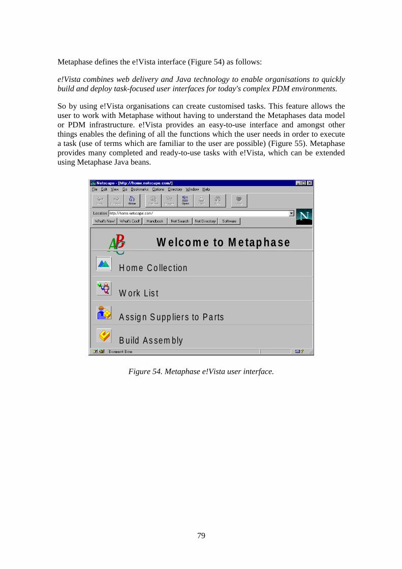
79
Metaphase defines the e!Vista interface (Figure 54) as follows:
e!Vista combines web delivery and Java technology to enable organisations to quicklybuild and deploy task-focused user interfaces for today's complex PDM environments.
So by using e!Vista organisations can create customised tasks. This feature allows theuser to work with Metaphase without having to understand the Metaphases data modelor PDM infrastructure. e!Vista provides an easy-to-use interface and amongst otherthings enables the defining of all the functions which the user needs in order to executea task (use of terms which are familiar to the user are possible) (Figure 55). Metaphaseprovides many completed and ready-to-use tasks with e!Vista, which can be extendedusing Metaphase Java beans.
Figure 54. Metaphase e!Vista user interface.
H om e C o llec tion
W elco m e to M e tap ha se
W ork Lis t
A ssig n S upp lier s to P a rts
B uild A s sem bly
AABBCC

80
Figure 55. Administrator task example.
Integrator Toolkit:
The Integrator Toolkit provides tools for system customisation. It is also possible tocreate customised interfaces to external tools by using the Integrator Toolkit. TheToolkit contains application programming interfaces and graphical tools forcustomisers.
The Metaphase Solution Series contains ready-to-use packaged EPDM applications,which require only the minimum amount of tailoring.
Meta Document Management (MetaDM):
MetaDM is a solution which allows document management as part of its productdefinitions. This document management consists of identifying, storing, controlling, anddistributing documents created by different applications. The solution offers thefollowing basic capabilities:

81
Authoring services:
Users who create and modify documents use authoring services. It is possible to workwith MetaDM in two ways: by using the authoring tool like Microsoft Office or byusing Metaphase user interface.
Explorer-User services:
Explorer users are people who work with documents. Users use e.g. commercial Web-browsers to access MetaDM. Users can find, view and print these documents (Figures56, 57, and 58).
Figure 56. Document search.

82
Figure 57. Results of document search.
Figure 58. Route document dialogue.

83
Workflow services:
By using MetaDM and Enterprise PDM companies are able to automate workflows e.g.for reviewing and approving documents, typically based on the quality procedures(Figure 59).
Figure 59. Approve document dialogue
Publishing services:
This service allows organisations to improve their publication process. MetaDM allowsauditing and maintaining past versions and revisions of documents.
Enterprise PDM and MetaDM:
Enterprise PDM and MetaDM together provide enterprise level document managementand PDM functionality. There are commonalities between these solutions but EnterprisePDM works on a broader scale. This combines documents, design geometry, andpart/configuration information into the product's definition.

84
MetaVPDM:
MetaVPDM is a visualisation component of the Metaphase Enterprise solution series.This application tries to optimise the early stages of product design by providingvisualisation tools together with other product data, for design teams to visualise newproduct ideas as CAD-neutral 3D models and product structures and meta-data (Figure60). MetaVPDM uses commercial Web-browsers and e-mail applications to exchangeproduct ideas and collaborate as product designs change.
Figure 60. MetaVPDM.
MetaCM:
MetaCM is a configuration management tool which provides product configurationmanagement during a product's life-cycle. It manages generic and specific features andproduct combinations to meet rapidly changing customer needs.
MetaSM:
MetaSM is a storage management component of the Metaphase Enterprise solutionseries. First the solution provides selective backup functions which also take intoaccount the relationships that exist between the metadata and globally dispersed product

85
data. Secondly, it makes integrity checking when there are multiple PDM databases.Thirdly, it provides restore functions when the files that are lost need to be rebuilt.
7.2.2 Metaphase solution for design data management
Data Management
Data Vault and document management:
Vault support storage of all data (documents, components, assemblies, files, etc). Thedatabase solution is based on relational database technology, which has an externalobject model. The system supports a federated environment. This means that there aremultiple repositories and the independent implementation of these repositories ispossible. Check-in and Check-out functions prevent unauthorised modifications. Meta-data definition is possible as well as backup operations.
Metaphase has the MetaDM solution for document management. The solution containsversion control, which allows one to follow changes and review a document history. Itis also possible to copy the same document for several designers (parallel modifications)and decide after modifications which one to check-in (content comparison is alsopossible).
Product structure management:
Metephase allows the user to define and modify product structures. The system allowscompanies to incorporate documents, and design geometry and part/configurationinformation into product definitions. So the PDM and MetaDM together allow theconfigurations where the components have references to documentation (any type)(Figure 61). The user can navigate in the structure and see sub-assemblies and parts aswell as define multiple views for the same product structure. The Metaphase productstructure can be "virtual", which means that the whole product's structure can containsub-structures from different design systems. The structure can contain alternate,substitute, and optional parts (Figures 62, 63, and 64). Metaphase supports the differentvariations of a basic structure as well as the creation of the complex one-kind-ofstructure (contains all variations) for highly specialised industries. It is possible to createand manipulate BOM as well as reconstruct past configurations and plan futureconfigurations.

86
Figure 61. Documents within part/product definitions.
Figure 62. Expanding product structure.
P ro d u c t s t ru c tu r eP ro d u c t s t ru c tu r e
A s s e m b lyA s s e m b lyA s s e m b lyA s s e m b ly
P a r tP a r t
P a r tP a r t
P a r tP a r tP a r tP a r t
P a r tP a r t
S t an d ardS t an d ard
D raw in gD raw in g
T e stp l an
T e stp l an
M an u a lM an u a l
S p ec i fica tio nS p ec i fica tio n
D raw in gD raw in g
C h a n g eo r d e r
C h a n g eo r d e r
C h a n g ere q u e st
C h a n g ere q u e st

87
Figure 63. Viewing substitute parts.
Figure 64. Product structure with substitute parts.
Classification and retrieval:
Relationships (see Figure 61) are possible between documents, parts and assemblies.This feature allows the user to attach supporting documentation to the product structureas well as find all related information about a document, part or assembly when a user issearching for information. Users can find, view and print all product-related documents.Searching is possible with the use of content-based requests (specific string) or byattribute based requests. After the search MetaDM provides a list of documents and auser can redefine his/her search. Once the user has located a particular document,
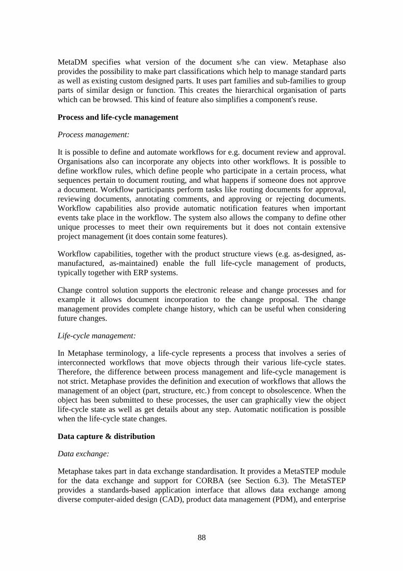
88
MetaDM specifies what version of the document s/he can view. Metaphase alsoprovides the possibility to make part classifications which help to manage standard partsas well as existing custom designed parts. It uses part families and sub-families to groupparts of similar design or function. This creates the hierarchical organisation of partswhich can be browsed. This kind of feature also simplifies a component's reuse.
Process and life-cycle management
Process management:
It is possible to define and automate workflows for e.g. document review and approval.Organisations also can incorporate any objects into other workflows. It is possible todefine workflow rules, which define people who participate in a certain process, whatsequences pertain to document routing, and what happens if someone does not approvea document. Workflow participants perform tasks like routing documents for approval,reviewing documents, annotating comments, and approving or rejecting documents.Workflow capabilities also provide automatic notification features when importantevents take place in the workflow. The system also allows the company to define otherunique processes to meet their own requirements but it does not contain extensiveproject management (it does contain some features).
Workflow capabilities, together with the product structure views (e.g. as-designed, as-manufactured, as-maintained) enable the full life-cycle management of products,typically together with ERP systems.
Change control solution supports the electronic release and change processes and forexample it allows document incorporation to the change proposal. The changemanagement provides complete change history, which can be useful when consideringfuture changes.
Life-cycle management:
In Metaphase terminology, a life-cycle represents a process that involves a series ofinterconnected workflows that move objects through their various life-cycle states.Therefore, the difference between process management and life-cycle management isnot strict. Metaphase provides the definition and execution of workflows that allows themanagement of an object (part, structure, etc.) from concept to obsolescence. When theobject has been submitted to these processes, the user can graphically view the objectlife-cycle state as well as get details about any step. Automatic notification is possiblewhen the life-cycle state changes.
Data capture & distribution
Data exchange:
Metaphase takes part in data exchange standardisation. It provides a MetaSTEP modulefor the data exchange and support for CORBA (see Section 6.3). The MetaSTEPprovides a standards-based application interface that allows data exchange amongdiverse computer-aided design (CAD), product data management (PDM), and enterprise

89
resource planning (ERP) systems. The module allows Metaphase EPDM systems toexchange product data with any design or data management system that supports PDMSchema (see Section 4.2). It is also possible to save files manually into the system.
The system contains the following interfaces:
• I-DEAS interface,
• Pro/ENGINEER Interface,
• AutoCAD Interface,
• FrameMaker Interface,
• Mentor Graphics Interface,
• SAP Interface,
• OracleManufacturing Interface,
• Unigraphics Interface, and
• Microsoft Office interface (Figures 65 and 66).
Figure 65. Microsoft Word interface containing e.g. check in and out functions.
90
Figure 66. Document Check in dialogue.
Thus the system contains integration with MCAD and ECAD design systems, andinterfaces/integrations with software design systems are underway. Nowadays, theSoftware Configuration Management system typically manages software product designand configuration, and released software product versions are then registered inMetaphase for the publishing of results outside the programmers' group (see Figure 40).
The I-DEAS interface connects the I-DEAS Team Data Management system andMetaphase-EPDM system. So this interface connects the team level system to theenterprise level system (see Figure 40). Items (such as assemblies, parts, and drawings)created and then put into I-DEAS libraries can be transferred to and from Metaphase.These items become Metaphase data items (item registration) when they are transferredto the Metaphase. This transfer moves items and all related sub-assemblies (relationsdefined in team level system) to the Metaphase. The connection can be furthercustomised for individual needs.
Mentor Graphics interface connects the Mentor Design Manager (team level datamanagement system) system and the Metaphase-EPDM system. This interface connectsthe team level system and the enterprise level system like in the I-DEAS interface.Figure 67 illustrates the schematic design by using Mentor and Metaphase. During thedesign process the electronics designers use registered standard components containedin Metaphase. These components can be browsed from Mentor and placed into theschematic with a single menu choice. If there is not a certain standard component it ispossible to register new components to the Metaphase and then use these components inMentor. Designers can register entire Mentor configurations including all data files andrelationships to Metaphase. The designer assigns part numbers to the top-level assemblyand other new components (or lets Metaphase automatically name them), and registersthe design in Metaphase. Metaphase product structures may be created from the dataand relationships contained in a Mentor design configuration. After that the designer

91
signs off his/her assigned tasks and data is transferred to the vault. It is worth noticingthat a design’s life-cycle state changes during design process and this can causeautomatic notification. The engineer who is responsible for the simulation task receivesnotification about the simulation task. The engineer checks out the schematic designfrom the vault and performs simulation activities. If there are no problems the engineersigns off his/her assigned task and the process continues with layout design.
Figure 67. Schematic design using Mentor and Metaphase.
Image services:
The system provides the possibility to view, comment and redline files. In the reviewprocess documents get copied to a local machine, and after review, possible redlinedcomments are related to the original file. Users can view the content of document andcomments in a universal format (e.g. PDF). The system automatically generates neutralviewing formats when the original information changes (e.g. PDF format). TheMetaVPDM solution allows designers to visualise the product ideas as well as performvirtual prototyping.
Global access, notification, and communication:
Distribution is possible via the Web or traditional client-interface: e!Vista provides fullfunctionality in Java, MetaWEB gives viewing and restricted editing capabilities inhtml/CGI, so-called classic client provides full functionality to non-Web clients. Serverload can be shared between workgroup and enterprise servers. Servers can bedistributed and/or federated or stand-alone. The system offers automatic notification onany event. This is useful e.g. during a review process. MetaVPDM allows easycommunication during early stages of the design. It also offers the possibility to addannotations to visualised material. MetaDM provides a "Document Inbox" that containsall the things which the person has to complete.
S c h e m a t icD e s ig n
P ro d u c tS tr u c tu re
G e n e ra t io n
W o rk O r d e r
D a ta T r a n s f e rto P ro je c t V a u l t
C ir c u i tS im u la t io n
S im u la t io nP a ss ed ?
N o
Y e s L a y o u t-d e s ig n
92
Methods
Design knowledge management:
The system supports knowledge management by providing all kinds of information forenterprise-wide distribution.
Concurrent engineering:
The system enables companies to automate processes and provides the possibility forconcurrent working. It enables early release of the information. It is also possible tocreate parallel revisions and choose which one to check-in. MetaVPDM supportsconcurrent engineering, allowing for the exchange of product ideas and for design teamsto collaborate. Some features of MetaVPDM are under construction but it providessolutions for the early engineering and design evaluation (visualisation with prductstructures and meta-data, virtual prototyping, and simulation). MetaCatalog is comingout to further help design re-use and standard part utilisation integrated with 3-Dgeometry libraries.
7.3 PVCS Dimensions
PVCS Dimensions is a product data management solution provided by Merant. PVCSDimensions has been chosen as part of this consideration because it has a strongconnection to the software design, which is one of the main technologies in anembedded product's design. The following information is based on interviews andexperiments provided by Software Engineering Center SEC, the reseller of PVCSDimensions in Finland.
7.3.1 PVCS Dimensions system overview
PVCS Dimensions is a process-based solution for product data management. It providesfeatures for:
• version management,
• configuration and workspace management,
• parallel development,
• distributed engineering,
• archive and retrieval,
• make and configuration build,
• change and problem management,

93
• impact analysis and traceability,
• process management and product structuring.
7.3.2 PVCS Dimensions for design data management
Data Management
Data Vault and document management:
PVCS Dimensions is based on industrial-standard relational database technology,implemented using the Oracle RDBMS (Relational DataBase Management System).This provides SQL access to the data and reports. PVCS Dimensions provides a centralmeta-database (object repository) and supports distributed development (multiplerepositories and central metadata). The system offers the possibility to check-outmultiple revisions and merge them when checked-in. It also supports role-based accesscontrol (e.g. certain files are available for persons defined as a Programmer). PVCSDimensions has the following object classes:
• product: a composite object made up of all the object classes and object instances,which identify the controlled objects;
• part: a basic building block which is a group of objects that supports change control,version control, software building and access control. These blocks form ahierarchical tree structure;
• item: a physical file which is in relationship with parts. Each item is owned by asingle part and may be used by one or more parts (reuse without physicalduplication);
• workset: a container for all the item revisions needed to complete the allocated task;
• baseline: a baseline captures the status and the content of a workset at a milestonepoint in a project;
• release: a tested baseline which is ready for the customer;
• change document: a document which is used in conjunction with product items tosupport change control and with product parts to support change tracking.
PVCS Dimensions provides a version management tool which also allows paralleldevelopment. The tool manages all files and also manages the data that does not resideon the file system (paper documents, books, etc.). All these versioned objects are storedunder a product configuration and the version-tree can be viewed graphically andreported textually. Versioned parts have attributes and relations embedded in them.

94
Product structure management:
The configuration in PVCS Dimensions is either dynamic or static. The dynamicconfiguration is a workset which is the collection of item revisions needed to complete aparticular task. The content of the workset is continually refined until the baseline isreached. The baseline is a snapshot which represents a development milestone (currentstate of a product) within a project's life-cycle. So it is a formally accepted usefulconfiguration at a certain moment (frozen configuration). It captures the structure anddetails and is used to build the configurations of the product for test and releasepurposes. So, a selected sub-tree of the product is captured, including parts,relationships (e.g. the "is-design-spec-of" relation between specification document andsource code) and status of each item. PVCS Dimensions does not allow anymodifications to the baselines (of course a new baseline is possible). PVCS Dimensionsprovides several types of baselines:
• release baseline: captures the details of product release. Contains only singlerevisions (e.g. source-code modules which are ready for the test);
• archive baseline: archives all revisions of certain items;
• merged baseline: contains selective items from the multiple release baselines;
• revised baseline: a release baseline which contains one or more related changedocument;
• design baseline: the structure of the product, which contains all related items.
Release is the configuration of the product, which is based on the release baseline. It ispossible to track what kind of design documents relate to the certain release and whohas bought that product. PVCS Dimensions also contain SW-build capability. Build,release and distribution features connect the customer's configurations and thecustomer's information.
When constructing product configuration the relationship between the items can be bothhierarchical and non-hierarchical. This feature, therefore, enables e.g. relations as "is-affected" between items. The users can view the structure to find particular objects.PVCS Dimensions also allows the creation of a "made of list" which represents the Bill-Of-Material and is available for navigation and reporting. The system also offers anoption to substitute component definition (Design Part Variant concept).
Classification and retrieval:
PVCS Dimensions allows system and user-defined attributes, which can be used whenretrieving objects. The system offers querying facilities to find certain objects. It alsouniquely identifies items and the user can access them by using different filteringcriteria (item type, object status, time-stamp, etc.).

95
Process and life-cycle management
Process management:
PVCS Dimensions allows the definition of unique process models to meet a company'srequirements. For example, it is possible to define one’s own change processes or usesupplied change management process models. The system provides reporting facilitiesand automatic routing of change documents as well as pending lists which containchange documents for which the user has some responsibility. The user can use changedocument templates, which specify the layout for all change documents. The templatecan contain any fixed text and it is applied dynamically each time the change documentis browsed. This means that template can be modified and modifications are updatedautomatically. The change document can be related to other change documents (e.g. aparent change document cannot be closed unless all of its daughter changes areimplemented and approved (parallel changes). The system offers impact analysis, whichannounces which other items have been built from the item, for example. The systemdoes not contain project management (but it does contain some features like processdefinition).
Life-cycle management:
The life-cycle feature is available for items, change documents, parts and baselines. Thelife-cycle contains a number of states and each transition between these states isassociated with one or more roles (e.g. project manager, programmer, etc.) and the usermust possess these authority roles in order to perform the transition. These roles alsodefine access to the life-cycle object. The life-cycle correlation rules allow thedefinition of state-defined functions that are available in a certain state (e.g. the user candefine that when an object has a "frozen" status it is not possible to attach change-documents to the objects). It is possible to track the life-cycle of the object. The systemalso allows document incorporation with the objects.
Data capture & distribution
Data exchange:
Using the data migration wizard it is possible to migrate existing data into PVCSDimensions (directories and/or files). PVCS version control commands offer code anddocument migration from SCCS (Source Code Control System). It is also possible tosave files manually into the PVCS Dimensions.
The system offers integration to several software tools (PDM functionality is availableto the user from within the software tool) but integration to ECAD or MCAD is notsupported. However, PVCS Dimensions provides an application programming interfacewhose functions support access to the PVCS Dimensions data structures and the abilityto call PVCS Dimensions commands. These functions can offer customised connectionsto design and management tools (MCAD, ECAD, and ERP). Application launching(opening a file in a correct application) is possible by using e.g. the operating system'sfile extension association. This association can be overwritten.
96
Image services
The PVCS Dimensions does not provide any image services. However, it is possible touse commercial viewers.
Global access, notification and communication:
Client/Server architecture allows the sharing of data anywhere on the network. PVCSDimensions also provides an Internet client for Web browsers but this feature offersonly a subset of the version and change management functionality. PVCS Dimensionsprovides the possibility for automatic e-mail notifications and pending lists (changecontrol).
Methods
Design knowledge management:
The system supports knowledge management by providing all kind of information forenterprise-wide distribution.
Concurrent engineering:
The system supports the early release of information as well as the file's status feature(preliminary information can have e.g. "concept" status). PVCS Dimensions supportsconcurrent working allowing parallel modifications and version merging. Figure 68illustrates the use of parallel worksets.
When the code changes don't overlap the merging can be done automatically. Ifoverlapping exists the conflicts must be solved using a graphical tool. PVCSDimensions also supports workset synchronisation. This means that the projects canhave integrated workset, which is automatically updated from nominated worksetsaccording to replication rules (automatic and continuous). Distributed paralleldevelopment is the extension of workset synchronisation, which provides replicationover a network.

97
Figure 68. Parallel development of worksets A, B, and C.
7.4 Observations
The classification which is represented in this report can be used when considering thecapabilities of a product data management system in the electronics industry (the reportemphasises embedded product design). According to this requirement classification,three commercial PDM systems (Windchill, Metaphase, PVCS Dimensions) wereconsidered. These systems offer many solutions for design data management althoughnone of them supports all the requirements defined in Chapter 5. The capabilities ofsystems depend on the PDM product vendor's different interests, backgrounds andtechnologies. Basic features like the data vault is well supported. The main feature,which is not fully supported, is tool integration, although the systems offer goodcapabilities for customised connections, for example by using application programminginterfaces. Other features whose capabilities depend on the system are:
• image viewing capabilities,
• project management,
• SW-build management,
• support for neutral data formats and data exchange, and
• support for concurrent engineering.
This report does not contain system comparison because the possibility of customising aPDM system makes it difficult to compare the capabilities of two systems. Some PDMsystems offer the possibility of using third-party programs for some specific tasks (likedocument viewers) which also complicates the comparison between PDM systemfeatures.
P V C S D im e n s io n sD a ta b a se
B a se lin e
W o rk se t A
W o rk se t C
W o rk se t B B a se lin eW o rk se t DM e rg e

98
8. Conclusions
The management of design data in the electronics industry in a global environment iscomplex. The design of an embedded product requires management of all design datacontaining different technologies, for example, software and electronics. Designdocuments, product structure and company's processes are strongly connected and thisrequires consideration which combines all these aspects.
This report describes the requirements for design data management in the electronicsindustry. These requirements are divided into three categories, although overlappingoccurs between categories. These categories are data management, process and life-cycle management, and data capture and distribution. However, this classification needsfurther consideration before it can be used as a comprehensive framework forexamining an embedded product's design data management solutions.
The solutions for design data management can be divided into three categories:enterprise-level, team-level, and design tool level. All these levels contain datamanagement features, and the features of every level can be exploited when enterprise-level management is considered in a company.
The system review section indicates that current systems do not meet all therequirements of the embedded product's design data management. Features which arenot fully supported, or depend on the system, are:
• tool integration (however, customised connections are possible),
• image viewing capabilities,
• project management,
• SW-build management,
• support for neutral data formats and data exchange, and
• support for concurrent engineering.
The electronics industry nowadays needs solutions for the enterprise level managementof design data. These solutions should be suitable for the management of complexproducts’ data and they should also support a company's work. However, companies’requirements vary and therefore different companies can end up with different kinds ofsolutions.

99
References
[AuT96] Auer A., Taramaa J. Experience report on the maturity of configurationmanagement for embedded software. 6th International Workshop onSoftware Configuration Management (SCM6). Berlin, Germany, 25–26March 1996. Heidelberg 1996, Lecture Notes in Computer Science. No:1167, pp. 187–197.
[AyJ96] Aylor J. H., Johnson B. W., Kumar S. The codesign of embedded systems.Kluwer Academic Publishers, 1996.
[BaB91] Bauer A., Bowden R., Browne J., Duggan J., Lyons G. Shop floor controlsystems. Chapman & Hall, 1991.
[BeE89] Bell P., Evans C. Mastering Documentation. John Wiley & Sons, 1989.
[Ber92] Berlack H. Software configuration management. John Wiley & Sons, 1992.
[Boe81] Boehm B. Software Engineering Economics. Englewood Cliffs, Prentice-Hall Inc., 1981.
[Boe88] Boehm B. A Spiral Model of Software Development and Enhancement,IEEE Computer, 21(1988)5, pp. 61–72.
[CDI99a] CDIF (Case Data Interchange Format) – Overview (Extract). ElectronicsIndustries Association, January 1994, 10.6.1999.http://www.eia.org/eig/cdif/electronic-extracts/OV-extract.pdf
[CDI99b] CDIF (Case Data Interchange Format) – CDIF Transfer Format GeneralRules for Syntaxes and Encodings (Extract). Electronics IndustriesAssociation, January 1994, 10.6.1999.http://www.eia.org/eig/cdif/electronic-extracts/GEN-extract.pdf
[Cut98] Cutler A. Design Management for Engineers. PCB Symposium, Design,Automation and Test in Europe, DATE, 1998. Pp. 124–139.
[Ele99] Electrical CAD tools to PDM integrations – Functional requirementsspecification. White Paper, International PDM Users Group (IPDMUG),21.5.1999. http://pdmic.com/IPDMUG/wpipdcad.html
[ElK97] Elovainio K., Kunz J. Docstep – Technical document management usingSTEP. SGML Europe '97. Barcelona, 13–15 May 1997. Barcelona, GraphicsCommunications Association, 1997. Pp. 43–53.

100
[ERP99] ERP to PDM Integration. White Paper, International PDM Users Group(IPDMUG), 2.11.1999. http://pdmic.com/IPDMUG/wp_erp_pdm.shtml
[HaH95] Halttunen V., Hokkanen M. Tuotetiedonhallinta. Taustaa ja ratkaisu-vaihtoehtoja [Product of data management]. Espoo 1995, TechnicalResearch Centre of Finland, VTT Tiedotteita – Meddelanden – ResearchNotes 1631. 75 p. (In Finnish.)
[HaL96] Van Den Hamer P., Lepoter K. Managing Design data: The FiveDimensions of CAD Frameworks, Configuration Management, and ProductData Management. Proceedings of the IEEE, 84(1996)1, pp. 42–56.
[Har98] Hars A. Better control with PDM. Byte (International), 23(1998)2, pp. 16–18.
[Haro98] Harold E. XML Extensible Markup Language. IDG Books Worldwide,1998.
[Hei97] Heikkinen M. A concurrent engineering process for embedded systemsdevelopment. Espoo 1997, Technical Research Centre of Finland, VTTPublications 313. 93 p.
[Her94] Herwijnen E. Practical SGML. Kluwer Academic Publishers, 1994.
[Ind94] Industrial automation systems and integration – Product data presentationand exchange – Overview and fundamental principles. InternationalOrganization for Standardization, ISO 10303-1, 1994.
[Inf95] Information technology – Software life cycle processes. InternationalOrganization for Standardization, ISO/IEC 12207, 1995.
[Joh99] Johnson J. F. E. The Sedres Project (Systems Engineering DataRepresentation and Exchange Standardisation – Extending STEP fromStructural Definition to Product Functionality. Proceedings of the 8thInternational Conference on CALS and Electronic Commerce in Europe,Sept. 1997, Frankfurt, Germany. Pp. 92–107.
[Kau99] Kauppinen S. Development of technological competitiveness by integratinginstruments and automation in process machinery. Department ofEconomics, University of Oulu, 1999.
[KeS92] Keller M., Shumate K. Software specification and design, A disciplinedapproach for real-time systems. John Wiley & Sons, 1992.
[Kiv98] Kivilahti J. Valmistuksen haasteet. Prosessori (special issue), 20(1998)4, pp.25–26. (In Finnish.)

101
[Kor96] Korpipää P. CAD-suunnittelutiedon hyödyntäminen mekatronisen laitteenkunnonvalvonnassa [Utilisation of CAD engineering information forcondition monitoring of mechatronic systems]. Espoo 1996, TechnicalResearch Centre of Finland, VTT Tiedotteita – Meddelanden – ResearchNotes 1759. 65 p. + app. 3 p. (In Finnish.)
[Lah98] Lahti M. Knowledge management – osaamisen organisaatio. Tietopalvelu,13(1998)3, pp. 17–18. (In Finnish.)
[Leb94] Lebland D. B. In: Tichy W. F. (ed.). The CM Challenge: ConfigurationManagement that Works. Configuration Management, John Wiley & Sons,1994.
[LeT99] Leppälä K., Taramaa J., Vuorinen O. Framework and tools for the quality ofR & D. Portland International Conference on Management of Engineeringand Technology – PICMET '99. Portland, OR, USA, 25–29 July 1999.Portland State University, IEEE, INFORMS, JSSPRM. Portland.
[MaM97] MacKrell J., Miller E., Mendel A. PDM Buyer's Guide. CIMData, 1997.
[Mau96] Maurer H. Hyperwave (The next generation web solution). Addison WesleyLongman, 1996.
[Mil98] Miller E. Managing Embedded Software. Computer-Aided Engineering,17(1998)12, p. 58.
[Mil99] Miller E. Focused Solutions Bring PDM to the Mainstream. Computer-Aided Engineering, 18(1999)1, p. 60.
[OiS98] Oivo M., Saukkonen S. Teollinen ohjelmistoprosessi (Ohjelmistoprosessinparantaminen SIPI menetelmällä).Tekes, 1998, Teknologiakatsaus 64/98.(In Finnish.)
[Oiv90] Oivo M. Knowledge-based support for embedded computer softwareanalysis and design. Espoo 1990, Technical Research Centre of Finland,VTT Publications 68. 82 p.
[PaS94] Pawar K.S., Sharifi S. In: Ladame M. (ed.). Product/Process Design:Integrating Differentiated Approaches. Proceedings of the SecondInternational Conference on Integrated Logistics & Concurrent Engineering,ILCE'94, Montpellier, France, February 7–11, 1994. France 1994, EC2,Nanterre. Pp. 37–46.
[Per87] Pere A. Koneenpiirustus 1. Offsetpiste, 1987. (In Finnish.)

102
[PeR96] Perkiö T., Ruppa E. Sähkötekninen dokumentointi. Helsinki 1996,Opetushallitus. (In Finnish.)
[Pes93] Pesonen P. Object-based design of embedded software. Espoo 1993,Technical research Centre of Finland, VTT Publications 143. 81 p.
[PeT98] Peng T., Trappey A. J. C. A step toward STEP – compatible engineeringdata management: the data models of product structure and engineeringchanges. Robotics and Computer-Integrated Manufacturing, 14(1998)2, pp.89–109.
[PiM96] Pikosz P., Malmqvist J. Possibilities and Limitations when IntroducingPDM Systems to Support the Product Development Process. ProceedingsNordDesign’96, Espoo, Finland, August 1996. Pp. 165–175.
[PiM97] Pikosz P., Malmström J., Malmqvist J. Strategies for Introducing PDMSystems in Engineering Companies. Proceedings of CE’97, FourthInternational Conference on Concurrent Engineering, Rochester, MI,August 1997. Pp. 425–434.
[PrS92] Priest J. W., Sanchez J. M., Paré K. In: Kusiak A. (ed.). Process Planningfor Electronics Component. Intelligent Design and Manufacturing, JohnWiley & Sons, 1992.
[Rah99] Rahikainen M. Sulautettujen järjestelmien ohjelmistotuotantoprosessintehostaminen yrityksessä. Raahe 1999. (In Finnish.)
[Roy70] Royce W. Managing the Development of Complex Software Systems:Concepts and Techniques. Proceedings, WESCON, 1970.
[Sal97] Sallinen J. AutoCAD 13 tehokkaaseen käyttöön. Jyväskylä 1997, Teknolit.(In Finnish.)
[Sep97] Seppänen V. In: Heinonen R. (ed.). Elektroniikka- ja sähköalankehitysnäkymät 1997…2002. Espoo 1997, Valtion teknillinen tutkimus-keskus (VTT). (In Finnish.)
[SoH98] Soininen J., Huttunen T., Saarikettu J., Melakari K., Ong A., Tiensyrjä K.InCo An interactive codesign framework for real-time embedded systems.Espoo 1998, VTT Elektroniikka.
[Soi97] Soininen J.-P. Asiakastarvelähtöisyys elektronisen tuoteperheensuunnittelussa [Customer-oriental development of electronic productfamily]. Espoo 1997, Technical Research Centre of Finland, VTT Julkaisuja– Publikationer 822. 111 p. + app. 18 p. (In Finnish.)

103
[Sto99] Stoles G. Integrating PDM (Product Data Management) with EDA tools.Electronic Engineering, 36(1999)4, pp. 57–60.
[SvM99] Svensson D., Malmström J., Pikosz P., Malmqvist J. A Framework formodelling and analysis of engineering information management systems.Chalmers University of Technology, Göteborg, Sweden, 1.12.1999.http://www.mvd.chalmers.se/~dpsn/reports/framework.pdf
[Sää98] Sääski J., Salonen T. Experiences in the STEP Implementation. Final Reportin: REMAP (Revision Management in Plant Design). ESPRIT project20270, 4th Framework Project, Information Technology, Integration inManufacturing, 1998.
[TaA99] Taura T., Aoki Y., Muranaka M., Ogawa T., Kohno Y., Yamada T.,Yamada Y. Knowledge Medium for the Global Design. PICMET '99, CD-ROM, Portland, 1999.
[Tar98] Taramaa J. Practical development of software conficuration managementfor embedded systems. Espoo 1998, Technical Research Centre of Finland,VTT Publications. 147 p. + app. 110 p.
[UlE95] Ulrich T., Eppinger D. Product Design and Development. McGraw-Hill,1995.
[Usa99] Usage Guide for the STEP PDM Schema. PDM Implementor Forum,August 13, 1999.http://www.pdm-if.org/pdm_schema/usageguide/pdmug_release3.PDF
[VTT97a] VTT Elektroniikan laatujärjestelmä – elektroniikkakehitys. ValtionTeknillinen Tutkimuskeskus (VTT), Elektroniikan tutkimusyksikkö, Oulu,1997. (In Finnish.)
[VTT97b] VTT Elektroniikan laatujärjestelmä – mekaniikkakehityksen työohje. ValtionTeknillinen Tutkimuskeskus (VTT), Elektroniikan tutkimusyksikkö, Oulu,1997. (In Finnish.)
[Wik98] Wikström K. Ohjelmoitavilla nopeasti markkinoille. Prosessori (specialissue), 20(1998)4, pp. 49–52. (In Finnish.)
[Wil97] Williams T. Software tools move toward automating process management.Electronic Design, 45(1997)4.
[WiP88] Winner R.I., Pennel J. The role of concurrent engineering in weaponsystems acquisition. Technical report, Institute for Defence Analyses,Alexandria, VA, December 1988, IDA Report R-338.

104
[Wor99] Workflow Management Coalition, Terminology & Glossary. WorkflowManagement Coalition, 7.12.1999.http://www.aiim.org/wfmc/standards/docs/glossy3.pdf

Published by
Vuorimiehentie 5, P.O.Box 2000, FIN-02044 VTT, FinlandPhone internat. +358 9 4561Fax +358 9 456 4374
Series title, number andreport code of publication
VTT Research Notes 2042VTT–TIED–2042
Author(s)
Kääriäinen, Jukka, Savolainen, Pekka, Taramaa, Jorma & Leppälä, Kari
Title
Product Data Management (PDM)Design, exchange and integration viewpoints
AbstractThe electronics and electrical industries have become an important branch of industry in Finland.They produce products which are used in health care, industry, and every-day living such asmobile phones, industrial instruments and automotive electronics.
In the global markets there are many competitors and companies seeking new ways to decreasecosts. This hard competition forces companies to specialise and focus on a certain market-segment. Products are containing more functionality, and product development is a continuousprocess to fulfil customer needs. Developers have to master a range of technology and the totalamount of product data is increasing.
This report describes the requirements of the embedded product's design data management.Analysis covers different product technologies as well as development processes. The challengeof the design data management is to manage the total set of data related to the structure of theproduct during the product's life-cycle.
The result of the analysis is the framework which represents the requirements of the design datamanagement of the embedded product. This classification contains three subsets: datamanagement, process and life-cycle management, and data capture and distribution.
This framework is used to evaluate three commercial PDM systems. This consideration bringsout the fact that the current solutions do not meet all the requirements of the embedded product'sdesign data management.
Keywords
design data management, embedded product design
Activity unit
VTT Electronics, Embedded Software, Kaitoväylä 1, P.O. Box 1100, FIN–90571 OULU, Finland
ISBN Project number
951–38–5684–4 (soft back ed.)951–38–5685–2 (URL:http://www.inf.vtt.fi/pdf)
E0SU00006
Date Language Pages Price
July 2000 English 104 p. C
Name of project Commissioned by
PRIMA2000
Series title and ISSN Sold by
VTT Tiedotteita – Meddelanden – Research Notes1235–0605 (soft back edition)1455–0865 (URL: http://www.inf.vtt.fi/pdf/)
VTT Information ServiceP.O.Box 2000, FIN–02044 VTT, FinlandPhone internat. +358 9 456 4404Fax +358 9 456 4374