v-ray for rhino - openlab.citytech.cuny.edu · material editor clicking the tag with “m” brings...
TRANSCRIPT

NEW YORK CITY COLLEGE OF TECHNOLOGYTHE CITY UNIVERSITY OF NEW YORK
V-RAY FOR RHINO
ARCHITECTURAL TECHNOLOGY DEPARTMENTwritten by Joseph Lim & Anne Leonhardt, with Felix Rodriguez
revised February 9, 2012 10:14 AM

V-RAY FOR RHINO
Table of Contents
• Getting Started
• V-Ray Render Options
• Material Editor
• Assigning Materials
• Using Texture Mapping
• Lighting
1
(1-2)
(2-3)
(4-9)
(10)
(11-22)
(23-24)

Getting Started
V-Ray Render Options
Clicking the tag with the “O” brings up the options boxfor V-Ray Render Options.
2
V-RAY FOR RHINO
To get started, click on Render > Current Render > V-Ray. TheMenu Bar will include V-Ray. Make sure that it is the current render.If it’s not, click it. You should see a toolbar for V-ray that looks like this:
If you don’t see the toolbar for V-Ray, click on the toolbar menu,and put a checkbox next to “VrayforRhinoV4.”

DEFAULT SETTINGS
The default preset options in V-Ray for Rhino are configuredwith relatively useful settings. Be careful not to adjust settingsunintentionally. However, if you do and you want to changethem back, in the options panel under file you can click on restore defaults.
In Render Options, V-Ray gives you the ability to adjust and manipulate the:
• Global Switches, • System,• Camera, • Output size of your Rendering, • Environment color emmittion, • Image Sample size, • Color Mapping, • Displacement opitons, • Indirect Illumination, • Irradiance Map
All these tabs open a section of adjustmentsaccording to your preference.
V-RAY FOR RHINO
3

Material Editor
Clicking the tag with “M” brings up the MaterialEditor box for V-Ray Render Options.
V-RAY FOR RHINO
4
V-Rays’s Material Editor has three parts:1. The materials workplace shows all the selected materials. Right clicking allows adding, importing, exporting, renaming, packing, removing, and selecting objects with current materials, such as assigning current materials to the selected objects or to the selected layers, deleting materials that are not used in the scene, and adding layers with reflections or refractions to the materials. 2. Material Preview.3. Options for material control. The options change with the added scene materials in section A.

5
Material: Diffuse Layer: The Diffuse Layer of a material applies a color to the material. The “M” box to the right applies pattern/textures and arranges sequences.
Transparency adjusts the opacity. Black is completely opaque and white is completely transparent. Grays represent interme-diate levels of transparency.
V-RAY FOR RHINO
Material: Reflection Layer
Click on the object you would like to add reflection to. Click on the Edit button under the Materialselections in the Property palette.
To add a reflection layer, click on the “+” next to the material under the Material Workspace to showall the layers. Right click on Reflection Layer. Select “Add new layer” to add a new reflection layer for this material. There will show Reflection under the material control section, as it shows on the right.

V-RAY FOR RHINO
6
By default, a fresnel map is on the reflec-tion layer, which is typically good unless the objects is chrome or mirror.
Fresnel Reflections are a naturally occurring phenomenon that states that an object be-comes more reflective the greater the angle at which it is seen. An example of this prin-ciple would be a window that is seen from straight ahead as opposed to at an angle. Through manipulating the Index of Refrac-tion (IOR) the reflective characteristics of an object can be changed. A lower IOR means that a larger angle is needed between the observer and the surface before the object begins to reflect. A higher IOR means that a smaller angle is needed, which in turn causes the object to reflect sooner. To have your renderings be more physically correct, it is recommended to have the IOR of an object correspond to its actual IOR.

V-RAY FOR RHINO
7
Click on Reflection in the right section of the Material Editor and then click on the m box to set Reflection. The Text Editor box ap-pears.
If it is not already enabled scroll down the box next to Type, and then select Fresnel. Fresnel IOR is to control the reflection inten-sity. The 1.55 default shows a slight amount of reflectivity, but changing above 10 produces striking reflectivity. Chrome has an IOR between 8 and 20.
Notice that the “m” on the right side of the Reflection in the Mate-rial Editor is now changed to “M”. This means the Map has some other characters associated with it now.
Above are six rendered samples each with a different Fresnel IOR. The last one is rendered with full reflection to create a chrome material.

V-RAY FOR RHINO
8
Reflection Glossiness
You don’t always get clear reflection from reflec-tive material. Objects like matte finish metal, wood and some plastic materials do not re-flect the environment clearly due to it uneven surfaces. This is because the uneven surfaces create many reflecting angles for light to bounce around. So the highlight is not as sharp if com-pared to reflection from smoother surfaces. The best way to create this kind of rendering quality is playing around the setting of both Highlight Glossiness and Reflection Glossiness.
The default value for both Reflection and High-light Glossiness is 1, which means that the reflections will be perfectly sharp. Once the value is decreased below 1 the reflections begin to become blurry.
A value of 0 would mean that the reflections are completely blurred, and this would look similar to a material without a reflection layer at all. Setting this for regular materials would cause extremely long render times. A good range for creating glossy reflections is be-tween .5 and 1. At values below .5 the effect is similar to a material without reflections.
Below are results from combinations of vari-ous intensities of Reflection Glossiness and Fresnel IOR.
V-RAY FOR RHINO
9
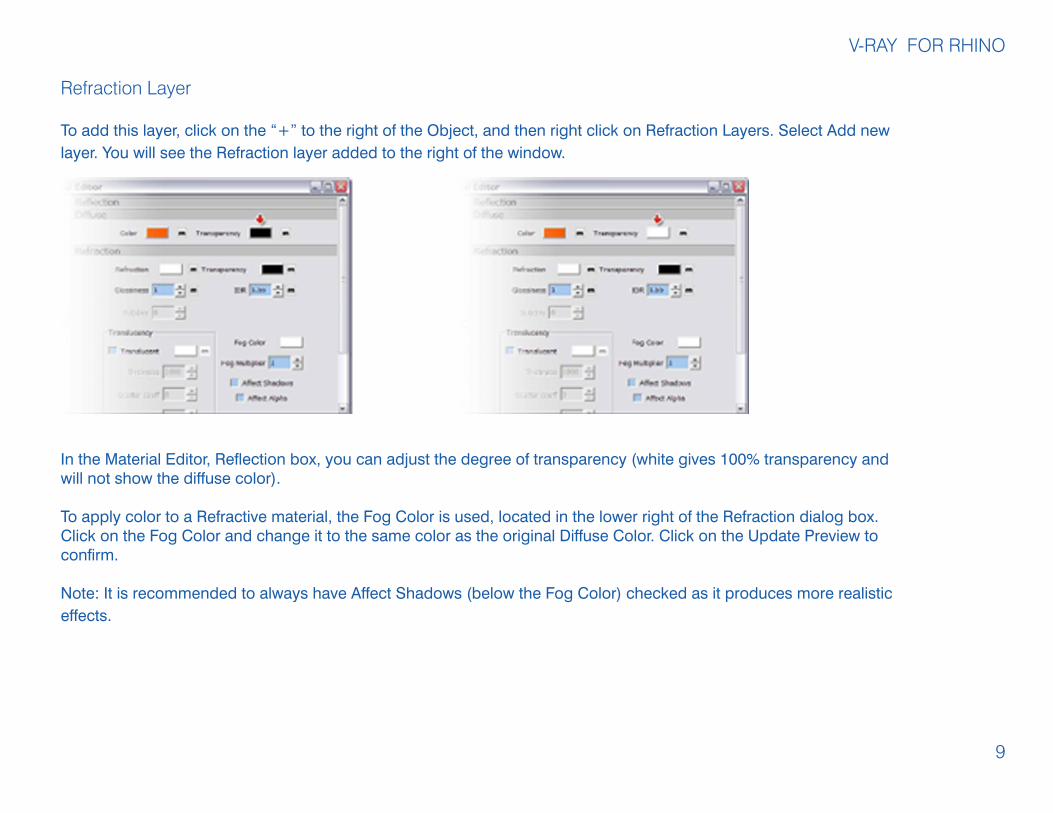
Refraction Layer
To add this layer, click on the “+” to the right of the Object, and then right click on Refraction Layers. Select Add new layer. You will see the Refraction layer added to the right of the window.
In the Material Editor, Reflection box, you can adjust the degree of transparency (white gives 100% transparency and will not show the diffuse color).
To apply color to a Refractive material, the Fog Color is used, located in the lower right of the Refraction dialog box. Click on the Fog Color and change it to the same color as the original Diffuse Color. Click on the Update Preview to confirm.
Note: It is recommended to always have Affect Shadows (below the Fog Color) checked as it produces more realistic effects.
V-RAY FOR RHINO
10
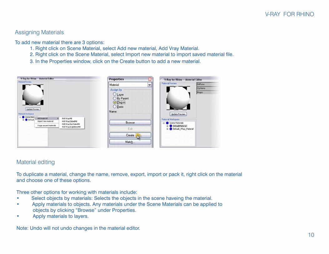
Material editing
To duplicate a material, change the name, remove, export, import or pack it, right click on the materialand choose one of these options. Three other options for working with materials include:• Select objects by materials: Selects the objects in the scene haveing the material.• Apply materials to objects. Any materials under the Scene Materials can be applied to objects by clicking “Browse” under Properties.• Apply materials to layers.
Note: Undo will not undo changes in the material editor.
Assigning Materials
To add new material there are 3 options: 1. Right click on Scene Material, select Add new material, Add Vray Material. 2. Right click on the Scene Material, select Import new material to import saved material file. 3. In the Properties window, click on the Create button to add a new material.

V-RAY FOR RHINO
11
Using Texture Mapping
Maps in V-Ray
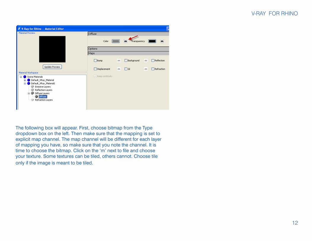
Image texture maps are applied to the diffuse layer of a material. Click on the ‘m’ next to the color box under the options panel of the diffuse panel.
V-RAY FOR RHINO
12
The following box will appear. First, choose bitmap from the Type dropdown box on the left. Then make sure that the mapping is set to explicit map channel. The map channel will be different for each layer of mapping you have, so make sure that you note the channel. It is time to choose the bitmap. Click on the ‘m’ next to file and choose your texture. Some textures can be tiled, others cannot. Choose tile only if the image is meant to be tiled.

V-RAY FOR RHINO
The following is a link to a tutorial for photoshop that shows you how to create a tile-able texture from a regular image:http://psd.tutsplus.com/tutorials/interface-tutorials/how-a-turn-a-texture-into-a-seamlessly-tiled-background/
Mapping requires that we set how the images are placed on our objects.Open the properties box for your object in Rhino and choose Mapping in the drop-down.Choose CustomClick the Advanced Properties Box
13

V-RAY FOR RHINO
Here is that channel again. Make sure it matches the channel for your texture.
The projection is important for the way that the texture maps itself onto the object. The following page covers all of the various types of projection available.
Depending on your choice for projection, you may need to rotate the texture to make it appear correctly.
If you have designed a non-tiling map, you may need to size it to your object so that it does not tile. Click the Size to Objects but-ton to stretch the texture to fit the object exactly.
This image shows what occurs if we just leave the object mapping at its default settings. V-ray uses the UV mappings of your objects to apply the texture map, making them go every which way. This is generally not a desirable effect.
14

V-RAY FOR RHINO
These images illustrate a planar mapping. Notice that the map is “flat” or co-planar with the x-y plane. This affects the way that the texture is applied.
This image illustrates what happens when we rotate the texture map 90 degrees to “stand up” and be be coplanar with the x-z plane
15

V-RAY FOR RHINO
These images show the various types of mapping available, box, spherical, cylindrical, and planar.
Bump Maps
Bump maps are created using the grayscale of the Bitmap to set the high and low texture. The bright part of the Bit-map is considered as high part and the dark is low. The Bump map is seen more clearly at the part where the object reflects the most of the light. Using Bump map texture to create bumped texture is only a visual effect, not the true surface of the object. Look at the edge of the object and you will still see the smooth surface.
16

V-RAY FOR RHINO
To add a sense of texture, apply the same material with the Bump Map feature, which is found under the Map box in the Material Editor. Note***: Use the same settings for tiling and projection that you used for the texture map so that the texture and bump map im-ages align. (see section above).
17

V-RAY FOR RHINO
Displacement Displacement allows you to recreate the texture of a surface by using a black and white image to describe the varying height of the surface. This is very similar to how bump mapping works, but each method does this in a different way. Bump mapping simply shifts the surface according to the image applied to it, with-out actually changing the geometric structure of the surface. This causes bump mapping to be somewhat limited in its capabilities of representing those surfaces. Displacement on the other hand actually creates the geometry that is described by the image. This is done by subdividing a given piece of geometry and adjusting the individual heights of all of the faces based on the image that it is describing. The result is a surface that produces a much more accurate and realistic result.
Adding Displacement
Using displacement is very similar to using bump mapping. In fact, you can probably use your current bump maps as displacement maps. In the Maps rollout of the material options there will be an option for Displacement. Enable displacement by clicking the check box on the left, and then proceed to click on the “m” to add a displacement map. Although textures are used for displacement maps in most situations it is possible to add a displacement map via the procedural mapping.Once either a texture or procedural mapping is added there is one last thing that you will have to pay at-tention to while still in the texture editor, and that is the multiplier. The multiplier is what is actually going to determine the final size of the displacement this will reference the Amount value in the Displacement roll-out.
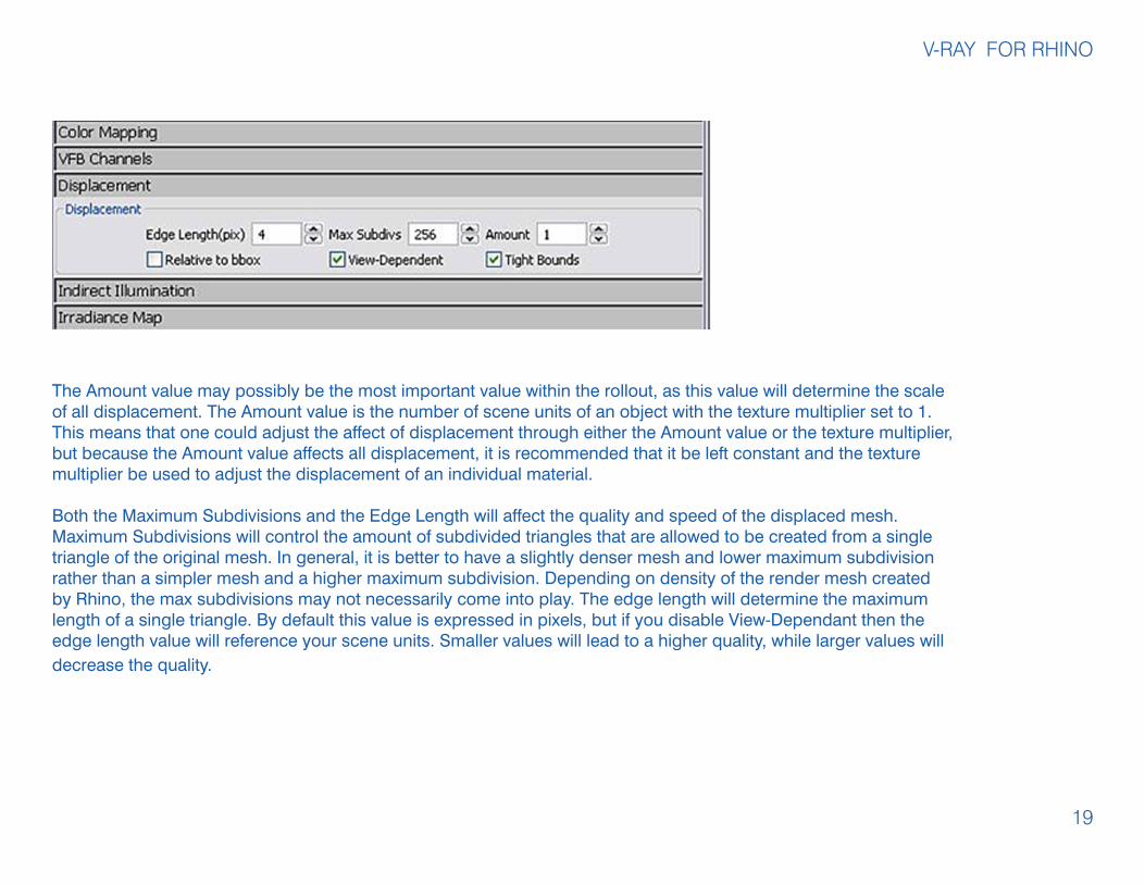
Displacement Parameters
In the V-Ray for Rhino Options there is a rollout which contains the parameters for displacement. It is im-portant to note that these are global controls for all of the displacement throughout the scene. Currently there is no individual controls on a per object or material level. This means that you must be aware of the settings within this rollout when adjusting an individual material’s displacement.
18
V-RAY FOR RHINO
The Amount value may possibly be the most important value within the rollout, as this value will determine the scale of all displacement. The Amount value is the number of scene units of an object with the texture multiplier set to 1. This means that one could adjust the affect of displacement through either the Amount value or the texture multiplier, but because the Amount value affects all displacement, it is recommended that it be left constant and the texture multiplier be used to adjust the displacement of an individual material.
Both the Maximum Subdivisions and the Edge Length will affect the quality and speed of the displaced mesh. Maximum Subdivisions will control the amount of subdivided triangles that are allowed to be created from a single triangle of the original mesh. In general, it is better to have a slightly denser mesh and lower maximum subdivision rather than a simpler mesh and a higher maximum subdivision. Depending on density of the render mesh created by Rhino, the max subdivisions may not necessarily come into play. The edge length will determine the maximum length of a single triangle. By default this value is expressed in pixels, but if you disable View-Dependant then the edge length value will reference your scene units. Smaller values will lead to a higher quality, while larger values will decrease the quality.
19
V-RAY FOR RHINO
Adjusting Displacement
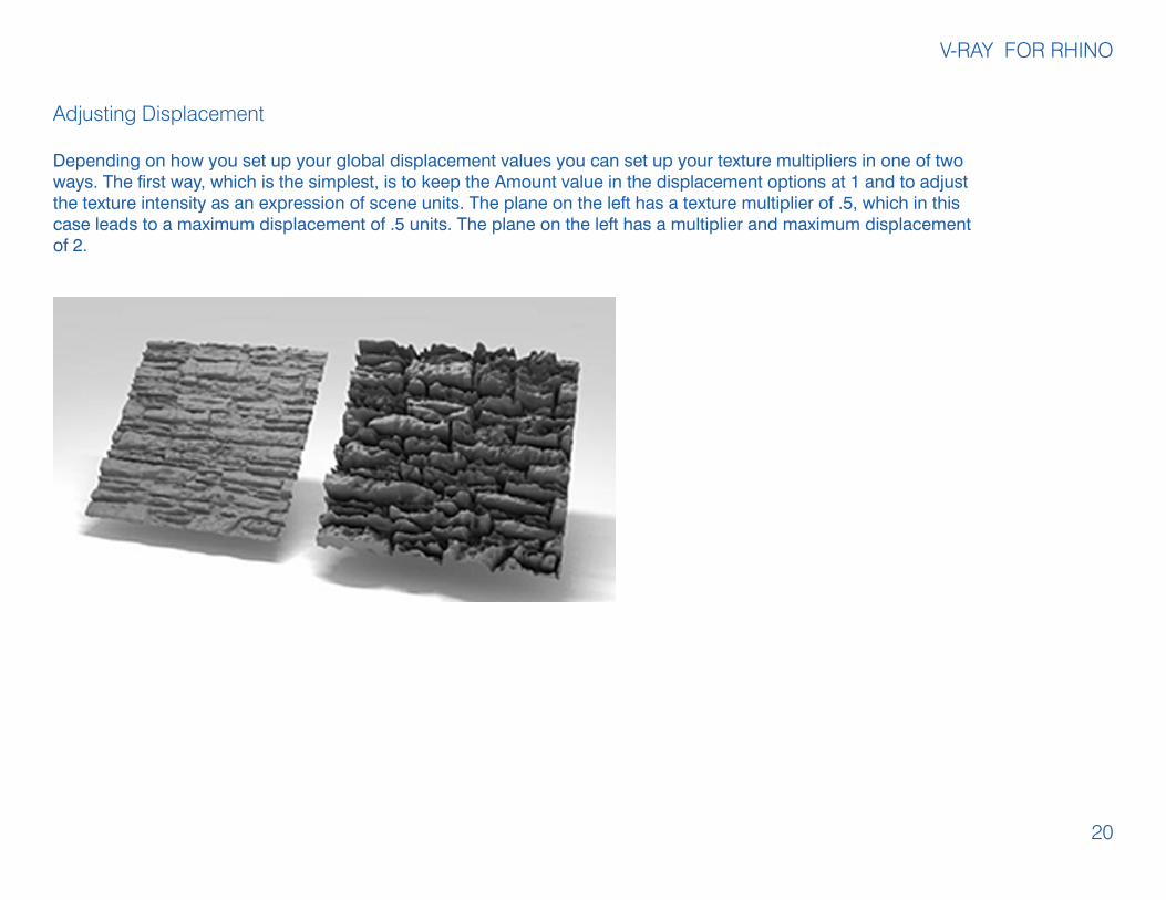
Depending on how you set up your global displacement values you can set up your texture multipliers in one of two ways. The first way, which is the simplest, is to keep the Amount value in the displacement options at 1 and to adjust the texture intensity as an expression of scene units. The plane on the left has a texture multiplier of .5, which in this case leads to a maximum displacement of .5 units. The plane on the left has a multiplier and maximum displacement of 2.
20

V-RAY FOR RHINO
Example 2
The image on the left is an example of the differ-ent quality settings for displacement. The plane on the left has an Edge Length of 24 pixels and a Maximum Subdivision of 6. The plane on the right has an Edge Length of 2 pixels and a Maxi-mum Subdivision of 512
21
Example 1
The second way to set up displacement by making the maximum displacement the Amount Value in the V-Ray options and setting the tex-ture multipliers as a percentage of that maximum value. It the case of the two planes to the right the Amount value is two. The plane on the left has a texture multiplier of .25 and the plane on the left has a multiplier of 1. You will notice that the rendered image is the same in both cases. That is because it is does not matter the method that is chose, only that the multipliers are in line with the desired effect

V-RAY FOR RHINO
Here is a comparison of bump mapping (left) and displacement (right). Both the maps and intensities are the same. As you can see the bump map is limited in its ability to create the depth that is capable with displacement.
22

Lighting
Basic Lighting w/ GI and Rectangular LightingYou will have noticed that the GI lighting does not create shadows as the light does not come from any direct source. To add more depth to your drawing, use the Rectangular light to add some smooth light-ing effects.
Click on the Spot Light icon on the Rhino toolbar. Select the Rect-angular light, the fourth from the left in the toolbar. Create the light in Top View and place it in Elevation at a distance above ground of approximately five times the height of your object.
V-RAY FOR RHINO
23
To edit the light properties, in the Properties palette, go to Object and scroll down to select Light.
Clear the No Decay option and change the Multipli-er from 1 to 4 (this controls the intensity of the light).
Parameters of Rectangular Light: Size, Distance and Multiplier (intensity).
Please note, shadows are larger, the smaller the light.
You can turn the light source off by checking Invis-ible. The light emitted, however, will still show in the scene.

V-RAY FOR RHINO
HDRI
HRDI images are images that can be used to produce atmospheric lighting effect. HDRIimages contain additional information regarding illumination levels, in addition to colorvalues. You can learn more about HDRI images from the following websites.
http://en.wikipedia.org/wiki/High_dynamic_range_imaginghttp://www.hdrmill.com/Freebies.htmhttp://www.yboo.net/hdri/
Open the render options tab
Once in the render options window open the “Environment” tab
Double click the “M” next to GI (skylight)
From the Type menu select Bitmap.
Once you have selected Bitmap. Double click the “m” under the bitmap tab.
Choose an HDRI file from the Materials library HDRI folder or that you have downloaded.
24