v. peplov - neutron sciences | neutron science at ornl · (scrs, snubber, firing, ... – one cap...
TRANSCRIPT

V. Peplov
January, 2012
SNS Linac
Modulator
Operations and
Performance
2 Managed by UT-Battellefor the U.S. Department of Energy
• SNS HVCM configuration
• HVCM downtime statistics
• Failure mode analysis
• Upgrades
• Plans
• Conclusion
Outline
3 Managed by UT-Battellefor the U.S. Department of Energy
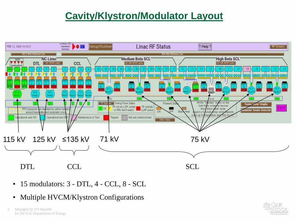
Cavity/Klystron/Modulator Layout
• 15 modulators: 3 - DTL, 4 - CCL, 8 - SCL
• Multiple HVCM/Klystron Configurations
115 kV 125 kV ≤135 kV 71 kV 75 kV
DTL CCL SCL
4 Managed by UT-Battellefor the U.S. Department of Energy
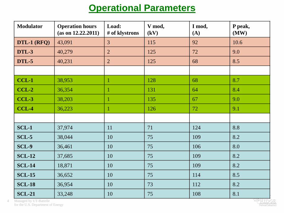
Modulator Operation hours
(as on 12.22.2011)
Load:
# of klystrons
V mod,
(kV)
I mod,
(A)
P peak,
(MW)
DTL-1 (RFQ) 43,091 3 115 92 10.6
DTL-3 40,279 2 125 72 9.0
DTL-5 40,231 2 125 68 8.5
CCL-1 38,953 1 128 68 8.7
CCL-2 36,354 1 131 64 8.4
CCL-3 38,203 1 135 67 9.0
CCL-4 36,223 1 126 72 9.1
SCL-1 37,974 11 71 124 8.8
SCL-5 38,044 10 75 109 8.2
SCL-9 36,461 10 75 106 8.0
SCL-12 37,685 10 75 109 8.2
SCL-14 18,871 10 75 109 8.2
SCL-15 36,652 10 75 114 8.5
SCL-18 36,954 10 73 112 8.2
SCL-21 33,248 10 75 108 8.1
Operational Parameters
5 Managed by UT-Battellefor the U.S. Department of Energy
HVCM Downtime
1. 7 runs considered for overview metrics
– Calendar Year runs: 2008-2 through 2011-2
2. Analysis of Downtime in CY-2011 – trips interrupted beam delivery only
– by months
– by sort of failures

6 Managed by UT-Battellefor the U.S. Department of Energy
HVCM Downtime Hours by Runs
0
50
100
150
200
250
2008-2 2009-1 2009-2 2010-1 2010-2 2011-1 2011-2
Run period
DT
Ho
urs
220
180
155
59
4049
23
(See following charts)
HVCM Downtime: unscheduled HVCM “OFF” time due to
any fault in HVCM system during beam delivery
HVCM Availability:
CY 2009 – 93.7%
CY 2010 – 98.3%
CY 2011 – 98.7%
HVCM Availability: a ratio of modulators total running hours
to total hours for NP and AP study in each run period

7 Managed by UT-Battellefor the U.S. Department of Energy
HVCM Downtime
(2010-1)
8.3
14%
22.5
38%
3.9
7%
6.5
11%
18
30%
SCL-12: IGBT switch plate
(2 kV Cap explosion, cable header arcing)
CCL-3: In-Tank
(rectifier stack)
SCL-18: SCR cabinet
(SCR, diode)
Others
RFQ: SCR cabinet
(AC Line fuse)
∑ = 59.2 Hours
• 4 events – 70% contribution
• More than 1 hour downtime shown separately
• Others: different types of faults; each less than 1 hour
8 Managed by UT-Battellefor the U.S. Department of Energy
HVCM Downtime
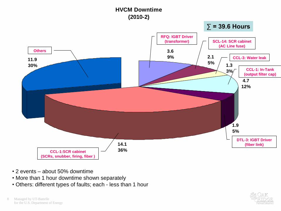
(2010-2)
3.6
9% 2.1
5%1.3
3%
4.7
12%
1.9
5%
14.1
36%
11.9
30%
∑ = 39.6 Hours
RFQ: IGBT Driver
(transformer) SCL-14: SCR cabinet
(AC Line fuse)
CCL-3: Water leak
CCL-1: In-Tank
(output filter cap)
DTL-3: IGBT Driver
(fiber link)
Others
CCL-1:SCR cabinet
(SCRs, snubber, firing, fiber )
• 2 events – about 50% downtime
• More than 1 hour downtime shown separately
• Others: different types of faults; each - less than 1 hour

9 Managed by UT-Battellefor the U.S. Department of Energy
HVCM Downtime: unscheduled HVCM “OFF” time due to any fault in HVCM system during beam delivery
Run Hours
2011-1
Feb. 10.5
March 3.2
Apr. 6.9
May 7.2
June 20.8
∑=48.6
2011-2
Aug. 3.9
Sep. 11.3
Oct. 0
Nov. 3.8
Dec. 3.6
∑=22.6
Σ 71.2
HVCM Downtime in CY-2011
0
5
10
15
20
25
Feb. March April May June July Aug. Sept. Oct. Nov. Dec.
Month
Ho
urs
Shut down

10 Managed by UT-Battellefor the U.S. Department of Energy
2011-1 (Feb. – July) 2011-2 (Sept. - Dec.)
Number of
events Hours
Number of
events Hours Σ Hours
Fault Type
HV Cable 3 20.3 0 0 20.3
SCR Water Leak (CCL-2) 2 9.2 0 0 9.2
Oil Pump 3 5.2 3 3.3 8.5
IGBT Switch/Driver 3 3.5 2 5.0 8.5
Control chassis (SCL-5, SCL-9) 0 0 2 6.7 6.7
Dynamic Fault (Mod RFQ) 0 0 28 6.2 6.2
Timing Faults 12 2.2 0 0 2.2
Water Panel Interlock 1 2.1 0 0 2.1
Voltage Dip (SCL-21) 4 0.5 0 0 0.5
Miscellaneous: Mod. OI, IGBT OI, SCR
OI, Flux sat., Dif. V, etc. Many ~6 Many ~2 ~8
Σ ~49 ~23 ~72
Downtime Statistical Data (CY-2011)
Notice: Beam breakdown events/hours shown
Hours By Faults

11 Managed by UT-Battellefor the U.S. Department of Energy
HV output cable damage
3 events during 2011-1:
• SCL-18, SCL-15 and CCL-2
• Downtime – 20.3 hours total
What happened:
• Long time in service
• Swelling in the oil
• Air bubble possible
• Insulator degradation
Result: Shorted / Arcing Cable
What was done:
• Damaged cables replaced and re-terminated
• New cables in 7 NCL modulators (Summer -2011)
• New cables in 4 SCL modulators (Jan. 2012)
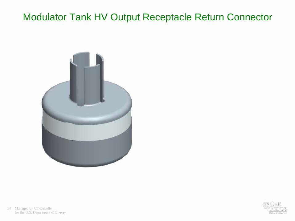
• Improved receptacle return connector (larger radius, no sharp edges) designed and manufactured
• Testing on RFTF
Plans:
• Complete replacement in SCL (Jan. 2012)
• Re-terminate cables with improved receptacle return connector

12 Managed by UT-Battellefor the U.S. Department of Energy
SCR cooling system: Water leak
What happened:
• Water leakage inside SCR cabinet on HVCM CCL-2 . Two failures in series. 9.2 hours downtime
• This type of failure has not occurred previously
Inspection revealed:
• Failed SCR Cooling Bus - Pinhole Leak with Corrosion
• Rough estimate ~ 0.01” wall thickness between Cooling Water Threads and Wall of Clearance Hole for SCR clamp
• The Clearance Holes for the SCR clamp do not centered in the Bus
• Suspect Repair: the wall of the Clearance Hole has been “soldered” (perhaps to repair a leak at the manufacturer)
What was done:
• Temporary replaced with other type spare bus
• New bar bus with +0.75” extended length fabricated
• Spare assembly tested and ready for installation
Plans:
• Install spare unit to HVCM CCL-2
• Fabricate improved parts
• Replace in all SCR cabinets according to schedule
Pinhole Leak with Corrosion
The wall of the Clearance Hole “Soldered”
Threads for Cooling Water Fittings
13 Managed by UT-Battellefor the U.S. Department of Energy
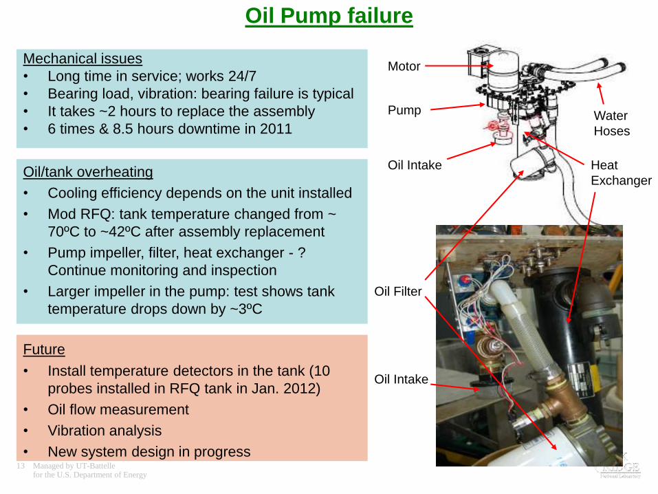
Oil Pump failure
Mechanical issues
• Long time in service; works 24/7
• Bearing load, vibration: bearing failure is typical
• It takes ~2 hours to replace the assembly
• 6 times & 8.5 hours downtime in 2011
Motor
Pump
Oil Filter
Heat
Exchanger
Oil Intake
Oil IntakeOil/tank overheating
• Cooling efficiency depends on the unit installed
• Mod RFQ: tank temperature changed from ~
70ºC to ~42ºC after assembly replacement
• Pump impeller, filter, heat exchanger - ?
Continue monitoring and inspection
• Larger impeller in the pump: test shows tank
temperature drops down by ~3ºC
Future
• Install temperature detectors in the tank (10
probes installed in RFQ tank in Jan. 2012)
• Oil flow measurement
• Vibration analysis
• New system design in progress
Water
Hoses

14 Managed by UT-Battellefor the U.S. Department of Energy
IGBT switch plate
4 kV/10 uF solid
TPC capacitor
2 kV/10 uF solid
NWL capacitor
IGBT driver card
• April 2011: Capacitor replacement completed; no oil-filled
capacitors on switch plates
• 5 events & 8.5 downtime hours during CY-2011
• New IGBT drivers installed on RFQ-modulator in Summer 2011;
testing continues
Plans:
• Install new intelligent drivers
•Test spare IGBT switch plates
on Single Phase Test Stand
•Test IGBTs using Tektronix
371A High Power Curve
Tracer
• Use IGBT snubber circuit
(development and testing in
progress)
15 Managed by UT-Battellefor the U.S. Department of Energy
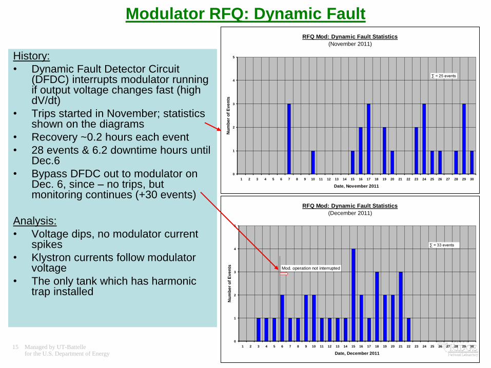
RFQ Mod: Dynamic Fault Statistics
(December 2011)
0
1
2
3
4
5
1 2 3 4 5 6 7 8 9 10 11 12 13 14 15 16 17 18 19 20 21 22 23 24 25 26 27 28 29 30
Date, December 2011
Nu
mb
er
of
Ev
en
ts Mod. operation not interrupted
∑ = 33 events
Modulator RFQ: Dynamic Fault
RFQ Mod: Dynamic Fault Statistics
(November 2011)
0
1
2
3
4
5
1 2 3 4 5 6 7 8 9 10 11 12 13 14 15 16 17 18 19 20 21 22 23 24 25 26 27 28 29 30
Date, November 2011
Nu
mb
er
of
Ev
en
ts
∑ = 25 events
History:
• Dynamic Fault Detector Circuit (DFDC) interrupts modulator running if output voltage changes fast (high dV/dt)
• Trips started in November; statistics shown on the diagrams
• Recovery ~0.2 hours each event
• 28 events & 6.2 downtime hours until Dec.6
• Bypass DFDC out to modulator on Dec. 6, since – no trips, but monitoring continues (+30 events)
Analysis:
• Voltage dips, no modulator current spikes
• Klystron currents follow modulator voltage
• The only tank which has harmonic trap installed
16 Managed by UT-Battellefor the U.S. Department of Energy
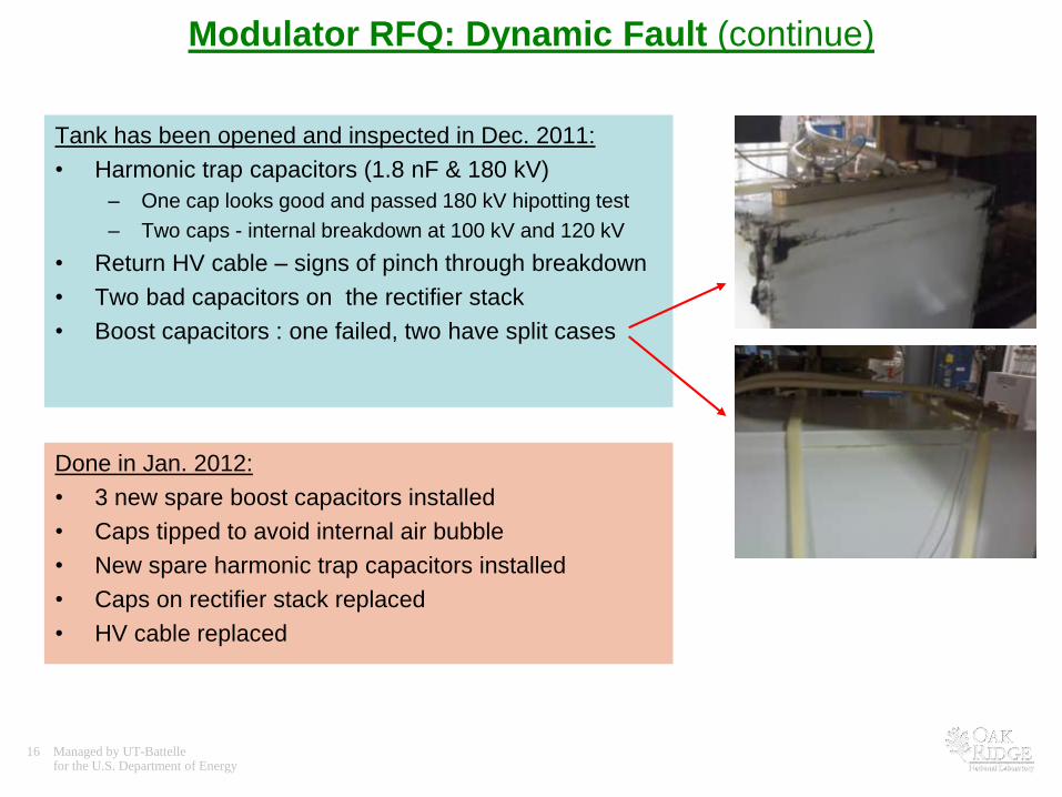
Tank has been opened and inspected in Dec. 2011:
• Harmonic trap capacitors (1.8 nF & 180 kV)
– One cap looks good and passed 180 kV hipotting test
– Two caps - internal breakdown at 100 kV and 120 kV
• Return HV cable – signs of pinch through breakdown
• Two bad capacitors on the rectifier stack
• Boost capacitors : one failed, two have split cases
Modulator RFQ: Dynamic Fault (continue)
Done in Jan. 2012:
• 3 new spare boost capacitors installed
• Caps tipped to avoid internal air bubble
• New spare harmonic trap capacitors installed
• Caps on rectifier stack replaced
• HV cable replaced

17 Managed by UT-Battellefor the U.S. Department of Energy
“In-Tank” boost capacitors (history)
Old 120 kV / 3100 pF GA capacitor (failed);
Replaced in Summer 2010
Jan. 2011 inspection:
New capacitors failure (brackets removed)
New 150 kV / 3100 pF CSI capacitors with brackets;
Installed in Summer 2010Capacitor’s Corner

18 Managed by UT-Battellefor the U.S. Department of Energy
January 2011:
• Upper brackets removed to avoid air traps
• Zip-straps used instead
• DTL and CCL (7 total) modulators upgraded
April 2011:
• CCL-3 tank inspection
• No signs of corona/arcing found
Summer 2011:
• DTL and CCL tanks: inspection - boost caps OK
Winter 2012:
• RFQ tank inspection
• Failed caps found - still remain the problem
Plans:
• 3 caps from RFQ – send to manufactory
• Inspect another tank in Jan. 2012
• 3 new SCL capacitors tested at full power
• Install into SCL tanks (Summer 2012 or regular
maintenance days)
“In-Tank” boost capacitors (history)
19 Managed by UT-Battellefor the U.S. Department of Energy
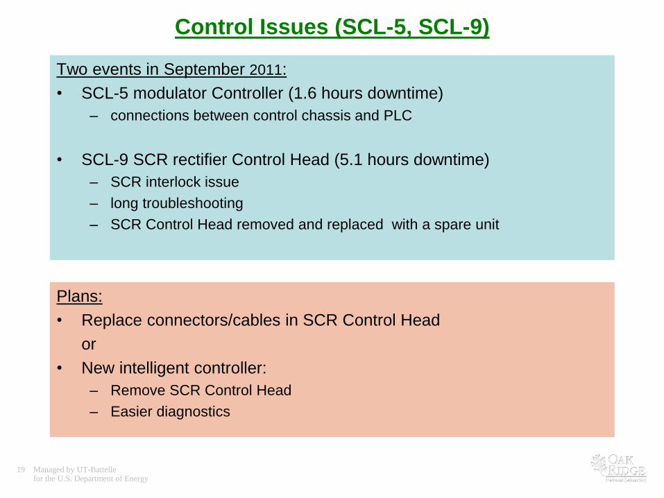
Control Issues (SCL-5, SCL-9)
Two events in September 2011:
• SCL-5 modulator Controller (1.6 hours downtime)
– connections between control chassis and PLC
• SCL-9 SCR rectifier Control Head (5.1 hours downtime)
– SCR interlock issue
– long troubleshooting
– SCR Control Head removed and replaced with a spare unit
Plans:
• Replace connectors/cables in SCR Control Head
or
• New intelligent controller:
– Remove SCR Control Head
– Easier diagnostics

20 Managed by UT-Battellefor the U.S. Department of Energy
Control Issues (SCL-21)
History:
• Modulator Voltage jumps cause Chatter Faults
• A lot of trips beginning October 2010
• 8 Trips in February 2011
• Long recovery
• Origin of faults - ?
– SCR cabinet
– Modulator
– Load
• Instrumented SCR Cabinet, Modulator and Klystron Currents
• Streaming EPICs data
Found:
• SCR regulation feedback signal “Positive Bus Current” drifts and has sudden steps
• SCR feedback signal moved to “Negative Bus Current” sensor for regulation – no
Voltage jumps since that time
• Current sensor on Positive Bus replaced
21 Managed by UT-Battellefor the U.S. Department of Energy
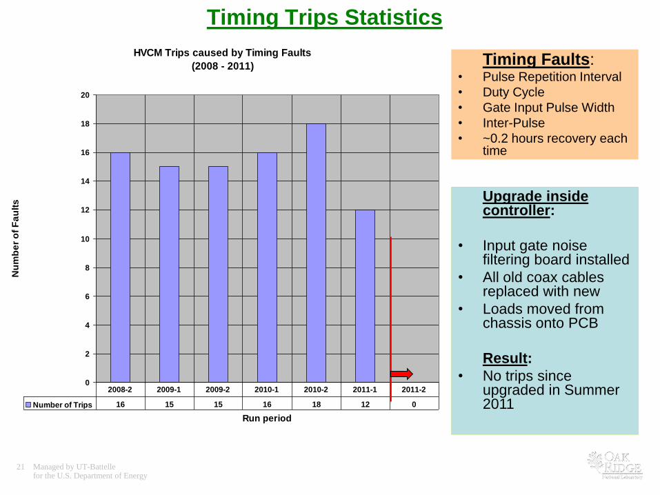
Timing Trips Statistics
Timing Faults:• Pulse Repetition Interval
• Duty Cycle
• Gate Input Pulse Width
• Inter-Pulse
• ~0.2 hours recovery each time
Upgrade inside controller:
• Input gate noise filtering board installed
• All old coax cables replaced with new
• Loads moved from chassis onto PCB
Result:
• No trips since upgraded in Summer 2011
HVCM Trips caused by Timing Faults
(2008 - 2011)
0
2
4
6
8
10
12
14
16
18
20
Run period
Nu
mb
er
of
Fa
ult
s
Number of Trips 16 15 15 16 18 12 0
2008-2 2009-1 2009-2 2010-1 2010-2 2011-1 2011-2
22 Managed by UT-Battellefor the U.S. Department of Energy
HVCM Upgrade
Other works during CY 2010-2011 outages:
• Output filter capacitors removed from all NCL modulator tanks
• New De-Qing resistors assembly, new voltage dividers and new cables installed in NCL modulator tanks in Summer 2010
• Forced air cooling system assembled in 8 SCR cabinets (2 - in 2010, 2 - in April 2011, and 4 - in Summer 2011)
– Air temperature inside SCR cabinet reduced from 180ºF to 90ºF (in RFQ modulator)
• Interlock connector on water panel box replaced (9 of 15 completed to the date)
• New IGBT drivers installed on 3 switch plates on RFQ modulator (Summer 2011)
23 Managed by UT-Battellefor the U.S. Department of Energy
• Upgrade SCL tanks (boost capacitors, de-Qing resistors, HV divider and HV cables)
• Complete SCR cabinet air cooling system assembling (7 more)
• Complete HV cables replacement in SCL modulators (Jan. 2012)
• Re-terminate HV output cables with improved return conductor
• Complete Interlock connectors replacement on Water panel (6 more)
• Checkout/replacement storage and switch plate capacitors
• Upgrade DC Bus Voltage and Current monitoring circuitry
• Upgrade modulator Output Current monitoring circuitry
• A bunch of miscellaneous items
Maintenance Plans
R&D efforts underway to support future activities:
• New IGBT gate driver implementation
• IGBT snubber circuit
• New intelligent FPGA based controller
• Oil cooling system upgrade (outside heat-exchanger)
• Series opening IGBT switch
• New HVCM topology
• “N+1” redundant H-bridge topology

24 Managed by UT-Battellefor the U.S. Department of Energy
CONCLUSION
• The HVCM system was a major contributor to the accelerator down time until 2009
• Thorough failure mode analysis done
• A lot of upgrades and modifications during last two years
• HVCM downtime reduced about factor of 10 (!) from 220 hours in 2008-2 running cycle to 23 hours in 2011-2
• Overall HVCM system availability increased from 93.7% in 2009 to 98.7% in 2011
25 Managed by UT-Battellefor the U.S. Department of Energy
Backup slides

26 Managed by UT-Battellefor the U.S. Department of Energy
Modulator RFQ: Dynamic FaultModulator trips Modulator stays running
V mod
V mod diff.
Ref. levels
I mod
I klystron 2
I klystron 1
Logic fault
Logic fault
I klystron 3

27 Managed by UT-Battellefor the U.S. Department of Energy
Feb. 15, 2011
Chatter Fault
15 Amp Step in Pos Bus Current
Mod Voltage, Pos & Neg Bus Currents at 1 Hz sample rate
Start up Feb. 28, 2011
7 Amp step in Pos Bus Current
causes 200V jump in Mod V

28 Managed by UT-Battellefor the U.S. Department of Energy
March 1, 2011:
SCR Feedback signal moved from Positive Bus Current sensor to Negative
SCL-21:
• Positive Current feedback signal
drifts and has sudden steps
• Changed to Negative Current
feedback signal for regulation –
no Voltage jumps
• Current sensor on Positive Bus
replaced
29 Managed by UT-Battellefor the U.S. Department of Energy
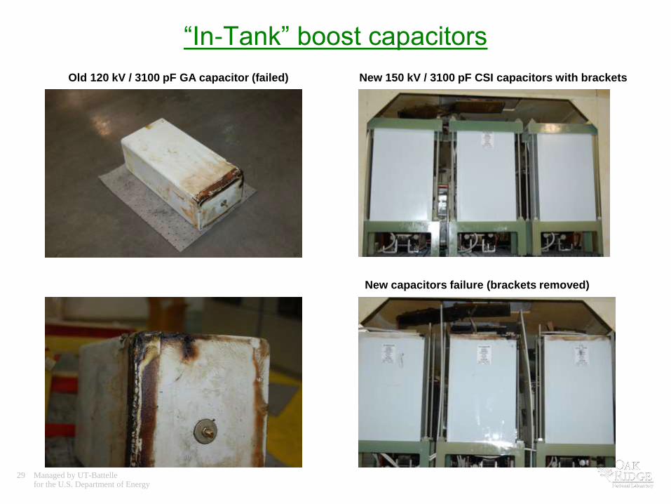
“In-Tank” boost capacitors
Old 120 kV / 3100 pF GA capacitor (failed) New 150 kV / 3100 pF CSI capacitors with brackets
New capacitors failure (brackets removed)

30 Managed by UT-Battellefor the U.S. Department of Energy
CCL4, RFQ – Damage on the caps
Cap Corners RFQ Brackets Cracks on the case
• Inspection in Jan. 2011 revealed the problem
• Analysis and simulation done (SNS and CSI)
• Mounting brackets changed

31 Managed by UT-Battellefor the U.S. Department of Energy
CSI Failure Analysis of RFQ/ CCL4 Caps
• Pictures from CSI
• All 7 capacitors repaired

32 Managed by UT-Battellefor the U.S. Department of Energy
• Presence of air bubbles either inside or external to the capacitor creates a problem where corona inception will eventually cause degradation of the surrounding insulation system and lead to catastrophic failure
• The upper brackets should be replaced with another style of bracket less likely to trap air
• The capacitor should be mounted at a slight angle to force any air that may be trapped internally away from the electrode since the manufacturer cannot guarantee that the unit will be bubble-free
• A follow-on inspection should occur at the next available opportunity to conform the mitigation strategy employed during the recent winter shutdown
• Further testing should continue on the virtually-equivalent SCL boost capacitors in the HEBT modulator for as much time as operational and other developmental demands will permit.
“In-Tank” boost capacitors
Analysis results*
*SNS WARM LINAC HIGH VOLTAGE CONVERTER MODULATOR (HVCM) BOOST CAPACITOR FAILURE ANALYSIS AND CONCLUSIONS
DAVID E. ANDERSON, FEBRUARY 25, 2011
33 Managed by UT-Battellefor the U.S. Department of Energy
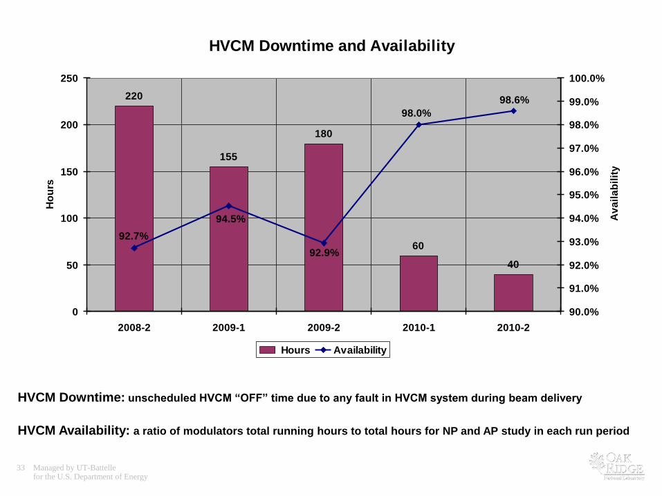
HVCM Downtime and Availability
220
155
180
60
40
92.7%
92.9%
94.5%
98.6%
98.0%
0
50
100
150
200
250
2008-2 2009-1 2009-2 2010-1 2010-2
Ho
urs
90.0%
91.0%
92.0%
93.0%
94.0%
95.0%
96.0%
97.0%
98.0%
99.0%
100.0%
Av
ail
ab
ilit
y
Hours Availability
HVCM Availability: a ratio of modulators total running hours to total hours for NP and AP study in each run period
HVCM Downtime: unscheduled HVCM “OFF” time due to any fault in HVCM system during beam delivery
34 Managed by UT-Battellefor the U.S. Department of Energy
Modulator Tank HV Output Receptacle Return Connector