v-line - gh binroth · 61.79 60.0 26.0 10 13.5 30 22 30 1) longer rails are supplied in sections...
TRANSCRIPT
V-Line
FS System

48
80°
H h
S
a
e
L
lll1
d
D
cfrom FS 19 MT up to FS 62 MT
=
=
FS 72 MT
1) Longer rails are supplied in sections with ground butt joints - 2) Weight without holes
3) Standard layout without pin holes (pin holes only on request)
Dimensions (mm)Type H
± 0.1h
± 0.1
FS 19 MT
FS 22 MT
FS 32 MT
FS 40 MT
21.0
27.0
42.0
62.0
5.3
5.8
6.8
8.8
4
5
6
6
6.5
6.5
6.5
9.0
15
15
15
20
–
–
–
–
–
–
–
–
90
90
90
90
30
30
30
30
22.20
28.80
43.80
FS 35 MT 47.0 8.8 6 9.0 20 – – 90 30 48.80
64.50
FS 52 MT 88.2 13.0 8 13.5 20 – – 90 30 91.35
FS 47 MT 77.2 11.0 6 11.5 20 – – 90 30 80.15
FS 72 MT
Maximum length of single guide element L = 6 000 mm (1)
121.0 19.0 10 17.5 30 30.5 60 90 30124.60
FS 62 MT 103.0 15.7 8 13.5 20 – – 90 30106.00
S± 0.1
d (3)
+ 0.05D c (3) e a l l1
0.8
1.1
2.1
4.1
3.0
8.5
6.3
16.9
11.7
Weight (2)
(kg/m)
V-Line
Guide rails FS..MT
Rails finishing- drawn,induction hardened and sandblasted tracks (MT);- induction hardening on raceways only
Hole layout- holes according to catalogue (SB)- finishes to drawing (NZ)- without holes (NF)
Optional features- ground one end (R) - ground both ends ( RR ) - chemical Nickel-plating (NW)- pin holes
Example of standard designation : FS 52 MT 5280 SB
See page 17 for standard codification

Dimensions (mm)Type H
± 0.05h
± 0.1
FS 19 M
FS 22 M (4)
FS 35 M (4)
20
26
46
4.5
5
8
4
5
6
6.5
6.5
9
15
15
20
–
–
–
–
–
–
90
90
90
30
30
30
20.95
27.86
FS 32 M 41 6 6 6.5 15 – – 90 30 42.86
47.86
FS 47 M (4) 76 10 6 11.5 20 – – 90 30 78.58
FS 40 M 61 8 6 9 20 – – 90 30 63.58
FS 62 M
Maximum length of single guide element L = 4 020 mm (1)
102 15 8 13.5 20 – – 90 30104.76
FS 52 M 87 12 8 13.5 20 – – 90 30 89.78
S± 0.05
d (3)
+ 0.05D c (3) e a l l1
0.6
0.9
2.6
1.8
5.6
3.7
11.2
7.7
Weight (2)
(kg/m)
FS 72 M 120 18 10 17.5 30 30 60 90 30122.98 15.8
1) Longer rails are supplied in sections with ground butt joints - 2) Weight without holes
3) Standard layout without pin holes (pin holes only on request) - (4) Size 22, 35 and 47 available in stainless steel (NX)
49
c
D
d
==
l
L
ll1
a
eA
S
hH
80°
A0,
02
from FS 19 M up to FS 62 M
FS 72 M
V-Line
Guide rails FS..M
Rails finishing- drawn, induction hardened and ground profile (M);- induction hardening on raceways only
Hole layout- holes according to catalogue (SB)- finishes to drawing (NZ)- without holes (NF)
Optional features- stainless steel (NX) (4)
- ground one end (R) - ground both ends (RR) - chemical Nickel-plating (NW) - pin holes
Example of standard designation : FS 40 M 2760 SB
See page 17 for standard codification

50
H h
S
e
c
D
ll1
d
l
L
FSH 80°FSX 90°
1) Longer rails are supplied in sections with ground butt joints - 2) Weight without holes
3) Standard layout without pin holes (pin holes only on request)
Dimensions (mm)
11.6
Type
Maximum length of single guide element L = 6 000 mm(1)
Weight (2)
(kg/m)
FSH 22 MT
H± 0.1
h± 0.1
S± 0.1
d (3)
+ 0.05D c (3) e l l1
23.0 5.8 5 6.5 15 9 90 30 1.023.90
FSH 32 MT
FSH 40 MT
FSH 52 MT
FSH 62 MT
FSH 72 MT
FSX 90 MT
29.0 6.8 6 6.5 15 11 90 30 1.529.90
36.0 8.8 6 9.0 20 16 90 30 2.437.20
39.2 13.0 8 13.5 20 17 90 30 3.740.75
49.2 16.0 8 13.5 20 17 90 30 5.750.75
59.2 19.0 10 17.5 30 20 90 30 8.260.85
61.0 26.5 10 13.5 30 22 90 3062.85
V-Line
Guide rails FSH..MT, FSX..MT
Rails finishing- drawn, induction hardened and sandblasted tracks (MT);- induction hardening on raceways and base only
Hole layout- holes according to catalogue (SB)- finishes to drawing (NZ)- without holes (NF)
Optional features- ground one end (R) - ground both ends ( RR ) - chemical Nickel-plating (NW) - pin holes
Example of standard designation : FSH 52 MT 5280 SB
See page 17 for standard codification

TypeH
± 0.05
11.0
Weight (2)
(kg/m)
Maximum length of single guide element L = 4 020 mm(1)
FSH 19 M
h± 0.1
S± 0.05
d (3)
+ 0.05D c (3) e l l1
18.5 4.5 4 6.5 15 8 90 30 0.618.98
FSH 22 M
FSH 32 M
FSH 40 M
FSH 52 M
FSH 62 M
22.0 5.0 5 6.5 15 9 90 30 0.822.93
28.0 6.0 6 6.5 15 11 90 30 1.228.93
35.0 8.0 6 9.0 20 16 90 30 2.136.29
38.0 12.0 8 13.5 20 17 90 30 3.439.39
48.0 15.0 8 13.5 20 17 90 30 5.249.38
Dimensions (mm)
FSH 72 M
FSX 90 M
58.0 18.0 10 17.5 30 20 90 30 7.659.49
60.0 26.0 10 13.5 30 22 3061.79
1) Longer rails are supplied in sections with ground butt joints - 2) Weight without holes
3) Standard layout without pin holes (pin holes only on request)
51
90
H h
A B
e
c
D
ll1
d
l
L
FSH 80°FSX 90°
0,02
AB
S
V-Line
Guide rails FSH...M, FSX...M
Rails finishing- drawn, induction hardened and ground profile (M);- induction hardening on raceways and base only
Hole layout- holes according to catalogue (SB)- finishes to drawing (NZ)- without holes (NF)
Optional features- ground one end (R) - ground both ends ( RR ) - chemical Nickel-plating (NW)- pin holes
Example of standard designation : FSH 40 M 2760 SB
See page 17 for standard codification
52
V-Line
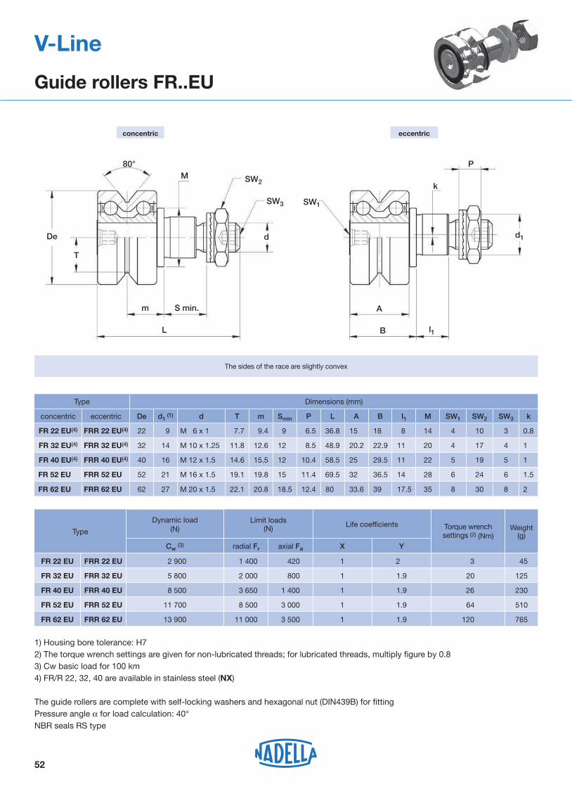
Guide rollers FR..EU
concentric eccentric
80°
De
T
m S min.
L
M
d
SW2
SW3 SW1
l1
A
B
k
P
d1
1) Housing bore tolerance: H72) The torque wrench settings are given for non-lubricated threads; for lubricated threads, multiply figure by 0.83) Cw basic load for 100 km4) FR/R 22, 32, 40 are available in stainless steel (NX)
The guide rollers are complete with self-locking washers and hexagonal nut (DIN439B) for fittingPressure angle α for load calculation: 40°NBR seals RS type
The sides of the race are slightly convex
Life coefficientsType Weight
(g)Torque wrench settings (2) (Nm)
3FR 22 EU FRR 22 EU
Dynamic load(N)
Cw (3) radial Fr axial Fa X Y
2 900 1 400 420 1 2
Limit loads (N)
20FR 32 EU FRR 32 EU 5 800 2 000 800 1 1.9
26FR 40 EU FRR 40 EU 8 500 3 650 1 400 1 1.9
64FR 52 EU FRR 52 EU 11 700 8 500 3 000 1 1.9
120
45
125
230
510
765FR 62 EU FRR 62 EU 13 900 11 000 3 500 1 1.9
Type Dimensions (mm)
concentric eccentric De d1 (1) d T m Smin P L A B I1 M SW1 SW2 SW3 k
FR 22 EU(4) FRR 22 EU(4) 22 9 M 6 x 1 7.7 9.4 9 6.5 36.8 15 18 8 14 4 10 3 0.8
FR 32 EU(4) FRR 32 EU(4) 32 14 M 10 x 1.25 11.8 12.6 12 8.5 48.9 20.2 22.9 11 20 4 17 4 1
FR 40 EU(4) FRR 40 EU(4) 40 16 M 12 x 1.5 14.6 15.5 12 10.4 58.5 25 29.5 11 22 5 19 5 1
FR 52 EU FRR 52 EU 52 21 M 16 x 1.5 19.1 19.8 15 11.4 69.5 32 36.5 14 28 6 24 6 1.5
FR 62 EU FRR 62 EU 62 27 M 20 x 1.5 22.1 20.8 18.5 12.4 80 33.6 39 17.5 35 8 30 8 2
53
V-Line
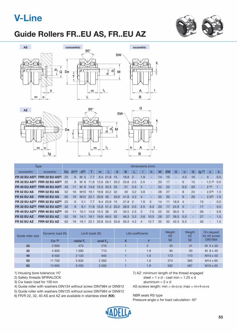
Guide Rollers FR..EU AS, FR..EU AZ
1) Housing bore tolerance: H72) Safety threads SPIRALOCK3) Cw basic load for 100 km4) Guide roller with washers DIN134 without screw DIN7984 or DIN9125) Guide roller with washers DIN125 without screw DIN7984 or DIN9126) FR/R 22, 32, 40 AS and AZ are available in stainless steel (NX)
7) AZ: minimum length of the thread engaged steel = 1 x d - cast iron = 1.25 x d aluminium = 2 x dAS screws length: min = d+o+s; max = m+4+o+s
NBR seals RS typePressure angle α for load calculation: 40°
Type Dimensions (mm)
concentric eccentric De d1(1) d(2) T m L A B l1 l h M SW G o Q Ig (7) s k
FR 22 EU AS(6) FRR 22 EU AS(6) 22 6 M 5 7.7 9.4 21.8 15 19.8 2 1.9 - 14 10 - 4.5 10 - 0 0.5
FR 32 EU AS(6) FRR 32 EU AS(6) 32 9 M 6 11.8 12.6 28.1 20.2 25.6 2.5 2.5 - 20 17 - 6 15 - 1.5 (4) 0.5
FR 40 EU AS(6) FRR 40 EU AS(6) 40 11 M 8 14.6 15.5 33.5 25 31 2.5 3 - 22 22 - 6.5 20 - 2 (4) 1
FR 52 EU AS FRR 52 EU AS 52 16 M10 19.1 19.8 43.2 32 40 3.2 3.8 - 28 27 - 8 24 - 2.5(4) 1.5
FR 62 EU AS FRR 62 EU AS 62 19 M12 22.1 20.8 46 33.6 41.8 4.2 4 - 35 30 - 9 26 - 2.5(5) 1.5
FR 22 EU AZ(6) FRR 22 EU AZ(6) 22 6 5.1 7.7 9.4 23.9 15 21.9 2 1.9 5 14 11 18.9 4 - 13 - 0.5
FR 32 EU AZ(6) FRR 32 EU AZ(6) 32 9 8.1 11.8 12.6 31.4 20.2 28.9 2.5 2.5 6.2 20 17 24.9 5 - 17 - 0.5
FR 40 EU AZ(6) FRR 40 EU AZ(6) 40 11 10.1 14.6 15.5 38 25 35.5 2.5 3 7.5 22 22 30.5 5 - 26 - 0.8
FR 52 EU AZ FRR 52 EU AZ 52 16 14.1 19.1 19.8 49.5 32 46.3 3.2 3.8 10.5 28 27 39.3 5.5 - 27 - 1.5
FR 62 EU AZ FRR 62 EU AZ 62 19 16.1 22.1 20.8 54.5 33.6 50.3 4.2 4 12.7 35 32 42.3 6.5 - 30 - 1.5
concentricAS eccentric
d1
m o
s
Q DeT
L
m
dd1
l1
M
SW80°
k
A
B
l
m o
lg
DeT
L
m
dd1
l1
M
SW
k
A
G
B
lh
AZ 80°
Guide roller sizeDynamic load (N) Limit loads (N) Life coefficients Weight
AS(g)
WeightAZ(g)
On request for AZ screw
DIN7984Cw (3) radial Fr axial Fa X Y
22 2 900 470 210 1 2 33 31 M 5 x 30
32 5 800 1 590 710 1 1.9 95 93 M 8 x 40
40 8 500 2 120 940 1 1.9 173 173 M10 x 50
52 11 700 5 830 2 560 1 1.9 374 365 M14 x 60
62 13 900 9 200 3 500 1 1.9 582 587 M16 x 65
Limit loads(N)
26,6 290
Weight(g)
Torquewrench (2)
settings(Nm)
1.8
Dynamic loads(N)
Cwr (4) radial Fr axial Fa
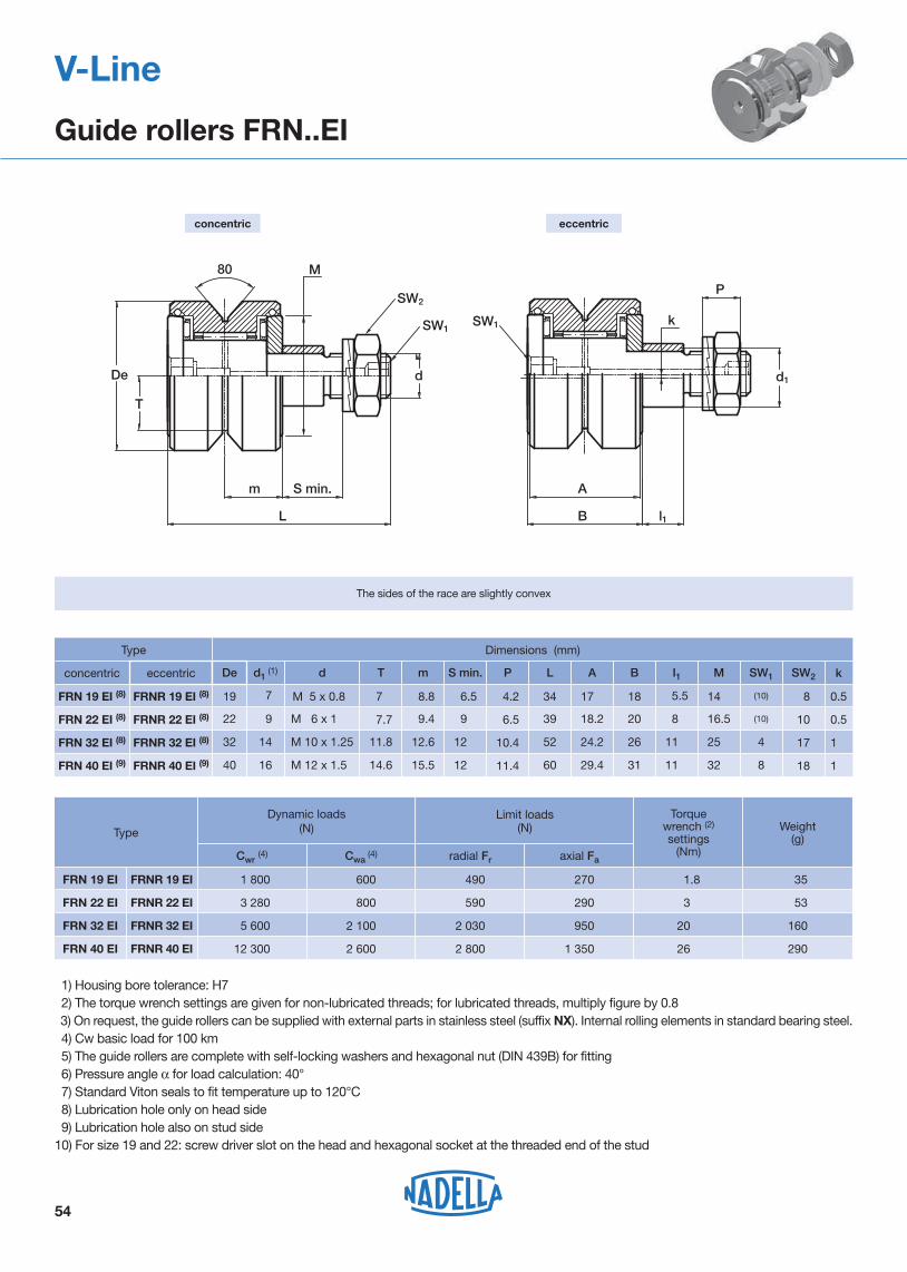
1 800 490 270
3,5 3 280 590 290
20,3 5 600 2 030 950
12 300
Cwa (4)
600
800
2 100
2 600 2 800 1 350
35
53
160
SW1
SW2
k
M
SW1
80
d
T
De
m
L
A
B l1
d1
P
S min.
The sides of the race are slightly convex
M 5 x 0.85
Type
Type
Dimensions (mm)
29.4
SW2
0.5FRN 19 EI (8)
concentric
FRNR 19 EI (8)
d1 (1) d T m S min. L A B I1 M SW1P
19 7 7.7 8.8 34 17.2 18 5.5 14,5 (10) 8 4.2
0.5FRN 22 EI (8) FRNR 22 EI (8) 22 9 M 6 x 1.25 7.7 9.4 39 18.2 20 8,5 16.5 (10) 10 6.5
1.5FRN 32 EI (8) FRNR 32 EI (8) 32 14 M 10 x 1.25 11.8 12.6 52 24.2 26 11,5 25.5 4 1710.4
1,5FRN 40 EI (9) FRNR 40 EI (9) 40 16 M 12 x 1.55 14.6 15.5 60 31 11,5 32,5 8 1811.4
k
6.5
9.5
12.5
12.5
1) Housing bore tolerance: H7 2) The torque wrench settings are given for non-lubricated threads; for lubricated threads, multiply figure by 0.8 3) On request, the guide rollers can be supplied with external parts in stainless steel (suffix NX). Internal rolling elements in standard bearing steel. 4) Cw basic load for 100 km 5) The guide rollers are complete with self-locking washers and hexagonal nut (DIN 439B) for fitting 6) Pressure angle α for load calculation: 40° 7) Standard Viton seals to fit temperature up to 120°C 8) Lubrication hole only on head side 9) Lubrication hole also on stud side10) For size 19 and 22: screw driver slot on the head and hexagonal socket at the threaded end of the stud
FRN 19 EI FRNR 19 EI
FRN 22 EI FRNR 22 EI
FRN 32 EI FRNR 32 EI
FRN 40 EI FRNR 40 EI
54
concentric eccentric
eccentric De
V-Line
Guide rollers FRN..EI

55
Dimensions (mm)
70
RKY 62
1
M
d
L
m
De
SW1
SW2
B I1
k=1
SW1
d1
P
T
A
RKX..90°RKY..80°
S min.
1) Housing bore tolerance: H72) The torque wrench settings are given for non-lubricated threads; for lubricated threads, multiply figure by 0.83) Standard seals: material NBR, RS type4) On request, the guide rollers can be supplied with external parts in stainless steel (suffix NX) and with Viton seals for operating
temperatures up to 120°C (suffix V, up to dimension RKX 90 C included). Internal rolling elements in standard bearing steel5) Cw basic load for 100 km6) Dimensions relating to the stainless-steel rollers (suffix NX)7) The guide rollers are complete with self-locking washers and hexagonal nut (DIN 439B) for fitting8) Pressure angle α for load calculation: guide rollers RKY 40° - guide rollers RKX 45°
56(6)
53
SW2
1RKY 52
Type
concentric eccentric
RKYR 52
De d1 (1) d T m S min. L A B I1 M SW1P
52 21 M 20 x 1.5 19.1 19.8 73 35 41 14 28 8 3013.4
1RKYR 62 62 27 M 24 x 1.5 22.1 20.8 83 37 44 18 35 10 3615.4
1RKY 72 RKYR 72 72 36 M 30 x 1.5 25.5 27.8 100 45 55 18 44 12 4621.6
1RKX 90C RKXR 90C 90 38 M 36 x 1.5 32.5 30 115 62 23 50 14 5524.6
k
RKY 52 RKYR 52
RKX 110C RKXR 110C 110 42 M 36 x 1.5 39.5 34.8
15
19
19
24
33 135 32 56 14 5524.6 63(6)
60
RKY 62 RKYR 62
RKY 72 RKYR 72
RKX 90C RKXR 90C
RKX 110C RKXR 110C
Limit loads (N) Life coefficients
4.9
Weight(kg)
Torque wrench (2)
settings(Nm)
80
Dynamic load(N)
Cw (5) radial Fr axial Fa X Y
40 750 11 900 4 250 1 3.38
160 46 000 22 100 6 800 1 3.13
300 64 850 31 300 10 100 1 2.96
450113 400 43 700 12 600 1 3.42
450
0.6
0.9
1.6
2.8
177 500 55 600 17 900 1 3.40
concentric eccentric
V-Line
Guide rollers RKY.., RKX..
The sides of the race are convex with radius R = 400.
Type
56
Type
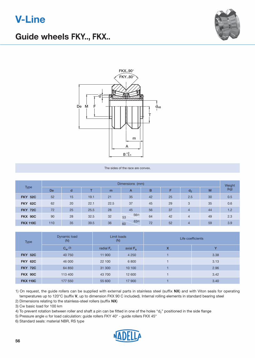
FKY 52C
FKY 62C
FKY 72C
FKX 90C
FKX 110C
d2
dH8De M
m
F
A
T
FKY..80°FKX..90°
B +0- 0.1
1) On request, the guide rollers can be supplied with external parts in stainless steel (suffix NX) and with Viton seals for operating temperatures up to 120°C (suffix V, up to dimension FKX 90 C included). Internal rolling elements in standard bearing steel
2) Dimensions relating to the stainless-steel rollers (suffix NX)3) Cw basic load for 100 km4) To prevent rotation between roller and shaft a pin can be fitted in one of the holes “d2” positioned in the side flange5) Pressure angle α for load calculation: guide rollers FKY 40° - guide rollers FKX 45°6) Standard seals: material NBR, RS type
Type
3.9
0.5
0.6
1.2
2.3
Dimensions (mm)
72
56(2)
53
FKY 52C
De d T m A B F d2 M
52 15 19.1 21,0 35 42 25 2.5 30
FKY 62C 62 20 22.1 22.5 37 45 29 3,0 35
FKY 72C 72 25 25.5 28,0 45 56 37 4,0 44
FKX 90C 90 28 32.5 32,0 64 42 4,0 49
FKX 110C 110 35 39.5 36,0 63(2)
60 52 4,0 59
Weight(kg)
The sides of the race are convex.
Limit loads(N) Life coefficients
radial Fr axial Fa
Dynamic load(N)
Cw (3) X Y
40 750 11 900 4 250 1 3.38
46 000 22 100 6 800 1 3.13
64 850 31 300 10 100 1 2.96
113 400 43 700 12 600 1 3.42
177 550 55 600 17 900 1 3.40
V-Line
Guide wheels FKY.., FKX..

57
The race ways are slightly convex
1) Housing bore tolerance: H72) The torque wrench settings are given for non-lubricated threads; for lubricated threads multiply figure by 0.83) Weight without fittings4) Cw = Basic load for 100 Km5) Dimensions for stainless steel (NX) version
Type Dimensions (mm)
concentric eccentric De d1 1) d T m Smin P L A B l1 M n X SW1 SW2 SW3 k
FRL 22 EU 5) FRLR 22 EU 5) 22 9 M6 x 1.0 7.7 7.5 9 6.5 39.3 15.0 20.5 8.0 14.0 1.5 2 4 10 3 0.8
FRL 32 EU 5) FRLR 32 EU 5) 32 14 M10 x 1.25 11.8 10.1 12 8.5 52.2 20.2 26.2 11.0 20.0 2 2 4 17 4 1.0
FRL 40 EU 5) FRLR 40 EU 5) 40 16 M12 x 1.5 14.6 12.5 12 10.4 61.4 25.0 32.4 11.0 22.0 2.4 2.5 5 19 5 1.0
FRL 52 EU FRLR 52 EU 52 21 M16 x 1.5 19.1 16.0 15 11.4 74 32.0 41.0 14.0 28.0 3 3 6 24 6 1.5
FRL 62 EU FRLR 62 EU 62 27 M20 x 1.5 22.1 16.8 18.5 12.4 83.6 33.6 42.6 17.5 35.0 3 3 8 30 8 2.0
TypeDynamic load (N) Limit load (N)
Limit load Inox version (N) NX
Torque wrench
setting 2)
(Nm)
Weight
(g) 3)
Cw 4) radial Fr radial Fr
FRL 22 EU FRLR 22 EU 2900 1050 980 3 46
FRL 32 EU FRLR 32 EU 5800 1700 1550 20 127
FRL 40 EU FRLR 40 EU 8500 3000 2750 26 233
FRL 52 EU FRLR 52 EU 11700 7600 6850 64 520
FRL 62 EU FRLR 62 EU 13900 11000 10300 120 776
concentric eccentric
Standard seals: material NBR, RS type
Guide rollers include self-locking washers and hexagonal nut (DIN 439B)
Pressure angle α for load calculation: 40°
V-Line
Floating guide rollers FRL..EU
80°X
M
De
T
m S min.
L
d
SW2
SW3 SW1
n P
k
d1
l1
A
B
58
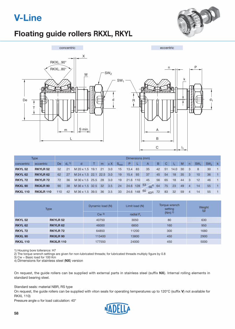
V-Line
Floating guide rollers RKXL, RKYL
1) Housing bore tollerance: H72) The torque wrench settings are given for non-lubricated threads; for lubricated threads multiply figure by 0.83) Cw = Basic load for 100 Km4) Dimensions for stainless steel (NX) version
Type Dimensions (mm)
concentric eccentric De d1 1) d T m ± X Smin P L A B C l1 M n SW1 SW2 k
RKYL 52 RKYLR 52 52 21 M 20 x 1.5 19.1 21 3.0 15 13.4 83 35 42 51 14.0 30 3 8 30 1
RKYL 62 RKYLR 62 62 27 M 24 x 1.5 22.1 22.5 3.0 19 15.4 93 37 45 54 18 35 3 10 36 1
RKYL 72 RKYLR 72 72 36 M 30 x 1.5 25.5 28 3.0 19 21.6 110 45 56 65 18 44 3 12 46 1
RKXL 90 RKXLR 90 90 38 M 36 x 1.5 32.5 32 3.5 24 24.6 128 53 564) 64 75 23 49 4 14 55 1
RKXL 110 RKXLR 110 110 42 M 36 x 1.5 39.5 36 3.5 33 24.6 148 60634) 72 83 32 59 4 14 55 1
TypeDynamic load (N) Limit load (N) Torque wrench
setting
(Nm) 2)
Weight (g)
Cw 3) radial Fr
RKYL 52 RKYLR 52 40750 3050 80 630
RKYL 62 RKYLR 62 46000 6850 160 950
RKYL 72 RKYLR 72 64850 11200 300 1680
RKXL 90 RKXLR 90 113400 13800 450 2900
RKXL 110 RKXLR 110 177550 24000 450 5000
On request, the guide rollers can be supplied with external parts in stainless steel (suffix NX). Internal rolling elements in standard bearing steel.
Standard seals: material NBR, RS type
On request, the guide rollers can be supplied with viton seals for operating temperatures up to 120°C (suffix V) not available for RKXL 110)Pressure angle α for load calculation: 40°
eccentricconcentric
SW2
RKXL..90°
RKXL..80°
De
T
SW1
m
L
S min.
X
M
d d1
l1C
B
A
R
n
k
P

59
Ø L
H
Ø D
V-Line
Spacers for FS and FSH
Optional features- steel
Finishing- anodized aluminium
The spacers, mounted between the guide and the supporting structure, guarantee adequate distance for the sliding of the rollers.The spacers DIST are designed for guides FS and FSH of V-Line and guides FSR of Multi-Motion-Line.
TypeDimensions (mm)
Suggested combinationsØL ØD H
DIST FS19 12 6.5 10 FS19, FSH19
DIST FS22 15 6.5 10 FS22, FSH22, FSR22
DIST FS32 30 6.5 15 FS32
DIST FS35 35 8.5 15 FS35, FSR35
DIST FS40 50 8.5 15 FS40
DIST FS47 60 10.5 15 FS47, FSR47
DIST FS52 65 12.5 20 FS52
DIST FS62 80 12.5 20 FS62
DIST FS72 35 16.5 20 FS72, FSH72
DIST FSH32 20 6.5 15 FSH32
DIST FSH40 25 8.5 15 FSH40
DIST FSH52 25 12.5 20 FSH52
DIST FSH62 25 12.5 20 FSH62
DIST FSX90 43 12.5 30 FSX90
Type
30
Suggested combinations
60
Weight(g)
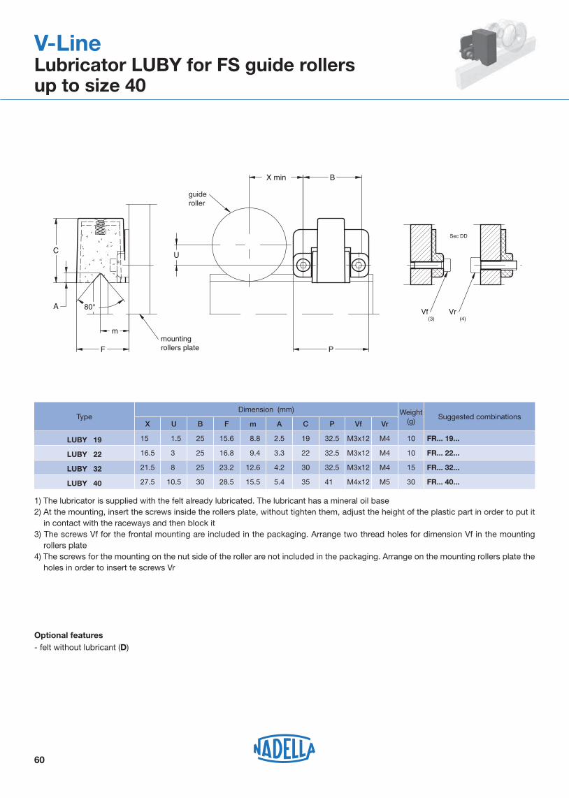
LUBY 19 FR... 19...
X
1015.5
Dimension (mm)
1) The lubricator is supplied with the felt already lubricated. The lubricant has a mineral oil base2) At the mounting, insert the screws inside the rollers plate, without tighten them, adjust the height of the plastic part in order to put it
in contact with the raceways and then block it3) The screws Vf for the frontal mounting are included in the packaging. Arrange two thread holes for dimension Vf in the mounting
rollers plate4) The screws for the mounting on the nut side of the roller are not included in the packaging. Arrange on the mounting rollers plate the
holes in order to insert te screws Vr
1.5 25 15.6 8.8 2.5 19 32.5 M3x12 M4
LUBY 22 FR... 22...1016.5 3.5 25 16.8 9.4 3.3 22 32.5 M3x12 M4
LUBY 32 FR... 32...1521.5 8.5 25 23.2 12.6 4.2 30 32.5 M3x12 M4
LUBY 40 FR... 40...27.5 10.5 30 28.5 15.5 5.4 35 41.5 M4x12 M5
U B F m A C P Vf Vr
V-LineLubricator LUBY for FS guide rollersup to size 40
guideroller
mountingrollers plate
Sec DD
80°
Optional features- felt without lubricant (D)
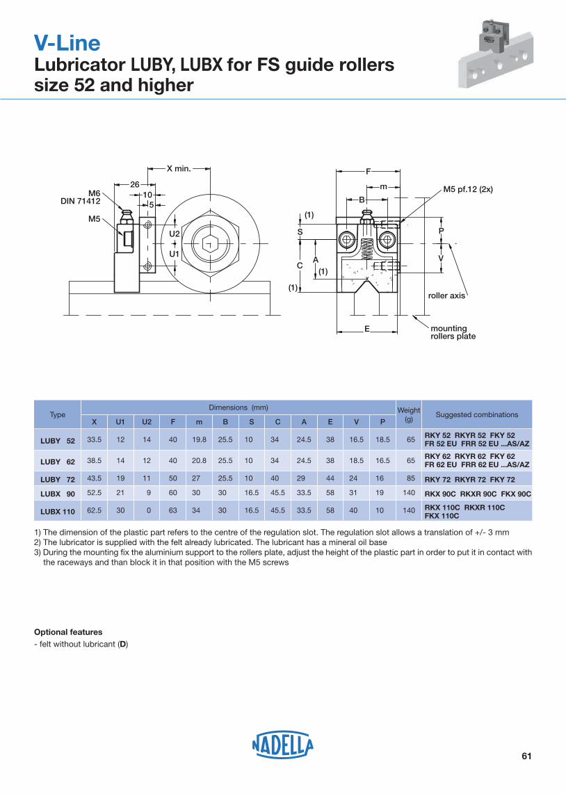
Type Suggested combinations
61
Weight(g)
LUBY 52RKY 52 RKYR 52 FKY 52FR 52 EU FRR 52 EU ...AS/AZ
X
6533.5
Dimensions (mm)
1) The dimension of the plastic part refers to the centre of the regulation slot. The regulation slot allows a translation of +/- 3 mm2) The lubricator is supplied with the felt already lubricated. The lubricant has a mineral oil base3) During the mounting fix the aluminium support to the rollers plate, adjust the height of the plastic part in order to put it in contact with
the raceways and than block it in that position with the M5 screws
12 14 40 19.8 25.5 10.0 34.5 24.5 38 16.5 18.5
LUBY 62RKY 62 RKYR 62 FKY 62FR 62 EU FRR 62 EU ...AS/AZ 6538.5 14 12 40 20.8 25.5 10.0 34.5 24.5 38 18.5 16.5
LUBY 72 RKY 72 RKYR 72 FKY 72 8543.5 19 11 50 27.0 25.5 10.0 40.5 29.4 44 24.0 16.0
LUBX 90 RKX 90C RKXR 90C FKX 90C14052.5 21 9 60 30.0 30.0 16.5 45.5 33.5 58 31.0 19.0
LUBX 110 RKX 110C RKXR 110CFKX 110C
14062.5 30 0 63 34.0 30.0 16.5 45.5 33.5 58 40.0 10.0
U1 U2 F m B S C A E V P
V-LineLubricator LUBY, LUBX for FS guide rollers size 52 and higher
Optional features- felt without lubricant (D)
F
2610
5
S
C
E
m
B
A
X min.
P
V
roller axis
M5 pf.12 (2x)M6DIN 71412
M5
U2
U1
mounting rollers plate
(1)
(1)
(1)

Ih (mm)Guide roller size
Guide roller size Guide roller size
*48
Guide roller size
FSH
..MT,
FS
X..M
T
FS..M
FS..M
T
FSH
..M, F
SX
..M
Guide rollers FR...EU, FR...EU AS, FR...EU AZ, FRN...EI, RKY, RKX, FKY, FRL..EU, RKXL, RKYL
62
FS FSH / FSX
Iy Ih
Iy (mm)
FS 19 M 3541.9
36.443.3
66.571.5 *77
92.8*107.8 116.8
128143
*134149
*167.2 174
19... 22... 32... 40... 52... 62... 72...
FS 22 MFS 32 MFS 35 MFS 40 MFS 47 MFS 52 MFS 62 MFS 72 M
FS 19 MT 36.2 37.644.2
67.472.4 *78
93.7*109.3 118.3
129.5144.2
*135.5150.2*168.8 175.6
19... 22... 32... 40... 52... 62... 72...
FS 22 MTFS 32 MTFS 35 MTFS 40 MTFS 47 MTFS 52 MTFS 62 MTFS 72 MT
FSH 19 M 26*29.9
26.730.6
40.750.9*54 58.5
*68.5
71.5*81.6 85
19... 22... 32... 40... 52... 62... 72...
94.3
90...
101.3
110...
FSH 22 MFSH 32 MFSH 40 MFSH 52 MFSH 62 MFSH 72 MFSX 90 M
Ih (mm)
FSH 22 MT 30.9 31.641.7*49 51.8
*55.4 59.9*69.9 72.9
*83 86.4
19... 22... 32... 40... 52... 62... 72...
95.3
90...
102.3
110...
FSH 32 MTFSH 40 MTFSH 52 MTFSH 62 MTFSH 72 MTFSX 90 MT
* possible combination
Iy (mm)
V-Line
Guide rollers combination

63
Waterjet cutting machineV-Line
V-Line
Mounting examples

64
V-Line
Mounting examples
Portable loader for steel sheetV-LineHeavy-Line