uzebox jamma revision c manual - wordpress.com · uzebox jamma to connect to the neo-geo jamma...
TRANSCRIPT
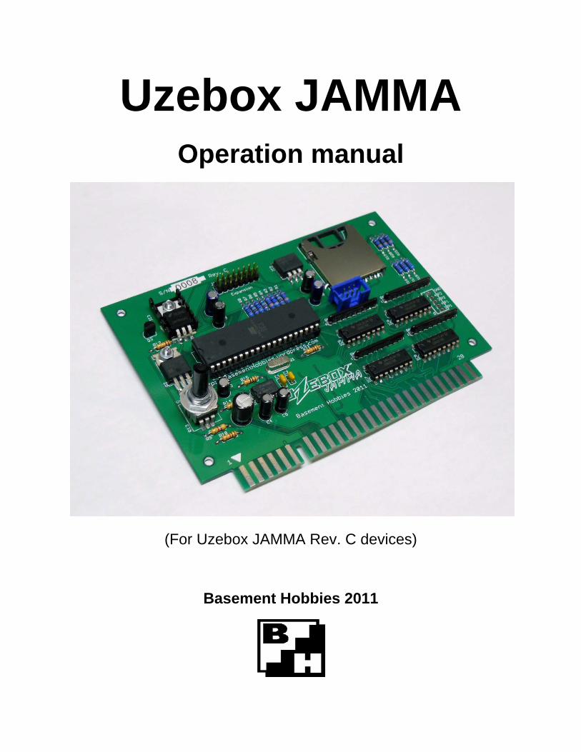
Uzebox JAMMA Operation manual
(For Uzebox JAMMA Rev. C devices)
Basement Hobbies 2011
Contents
Warnings 2
Introduction 3
Materials 4
Overview 5
Installation 6
Operation 7
Troubleshooting 13
Contact 16
1
Warnings
DISCLAIMER
Basement Hobbies is NOT liable for any actions taken by the user. It is recommended that the user of this device is aware of possible safety hazards that may occur while installing or using this device. Any injury caused by or damage done by this device is
under the user's responsibility as well as any malfunction of the device caused by improper construction or tampering.
NEO-GEO COMPATIBILITY
Please note the Uzebox JAMMA's edge connector pin-out DOES NOT match that of the Neo-Geo's JAMMA harness. A proper JAMMA converter board is required for the
Uzebox JAMMA to connect to the Neo-Geo JAMMA harness. The use of the Uzebox JAMMA inside of an original Neo-Geo cabinet without a proper converter board will
damage either the Uzebox JAMMA or parts inside of the Neo-Geo cabinet.
ELECTRO-STATIC SENSITIVITY
This device is static sensitive and must be grounded properly. Ensure the Uzebox JAMMA board is properly grounded before use.
PROFIT AND LEGAL
It is required that if a game/program designed for the Uzebox JAMMA is to be used in a public location or in the process of generating revenue that permission be requested
from the developer(s) of the game/program. Be aware of any required licensing needed to legally generate revenue.
WARRANTY
All devices sold by Basement Hobbies are tested. As stated in the disclaimer, any malfunction of the device caused by improper construction or tampering is the user's
responsibility. In the case that any components are missing or defective, contact Basement Hobbies.
2

Introduction
The Uzebox JAMMA is retro-minimalist 8-bit arcade development board based on the Uzebox Project. Driven by the ATmega644 AVR microcontroller by Atmel, this device can be easily programmed in the C programming language. Video generation, tile generation, and music mixing are done in real time by the ATmega's interrupt routine. The goal of the Uzebox JAMMA was to make homebrew arcade game development as simple as possible with good enough graphics and sound capabilities for creative games. With the use of SD card storage, games can be shared amongst users and easily loaded onto the Uzebox JAMMA.
The Uzebox JAMMA provides support for two player control inputs (consisting of 1 joystick and four buttons per player), 1 and 2 player start buttons, coin mechanisms, service switch, tilt switch, test switch. The behavior of these inputs may vary based on the current game/program loaded.
By default, the Uzebox JAMMA supports horizontal monitor orientation. Both horizontal and vertical monitor orientation are supported based on the current game/program loaded.
3
Materials
The following are included in this package:
Item: Quantity:
Uzebox JAMMA / Uzebox JAMMA kit x1
Operation manual x1
Uzebox JAMMA cabinet ID card x1
If any parts are missing or damaged, please contact Basement Hobbies.
4
Overview
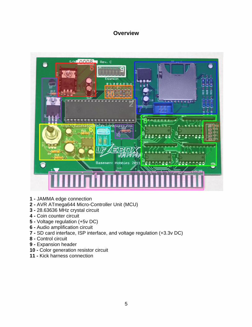
1 - JAMMA edge connection 2 - AVR ATmega644 Micro-Controller Unit (MCU) 3 - 28.63636 MHz crystal circuit 4 - Coin counter circuit 5 - Voltage regulation (+5v DC) 6 - Audio amplification circuit 7 - SD card interface, ISP interface, and voltage regulation (+3.3v DC) 8 - Control circuit 9 - Expansion header 10 - Color generation resistor circuit 11 - Kick harness connection
5
Installation
The Uzebox JAMMA requires that an arcade cabinet supporting a JAMMA harness be setup properly with the following:
-Standard JAMMA harness (See warnings for Neo Geo cabinets)
-Monitor (Horizontal and vertical orientation supported)
-Speaker
-Control panel
-Coin door with coin mechanisms and coin counter
-Power supply outputting +12v DC
Step 1 -
Power off arcade machine, disconnect power plug from wall socket, open cabinet for motherboard access.
Step 2 -
Remove currently installed motherboard from cabinet by un-mounting board from cabinet and disconnecting JAMMA harness and any other types of connection.
Step 3 -
Attach Uzebox JAMMA board to JAMMA harness and mount to cabinet*. NOTE: When attaching JAMMA harness to Uzebox JAMMA, ensure notch and/or pin 1 align.
Step 4 -
Close cabinet, plug in cabinet power, and power cabinet on.
*Mounting stand-offs/brackets are NOT included in this package.
6
Operation
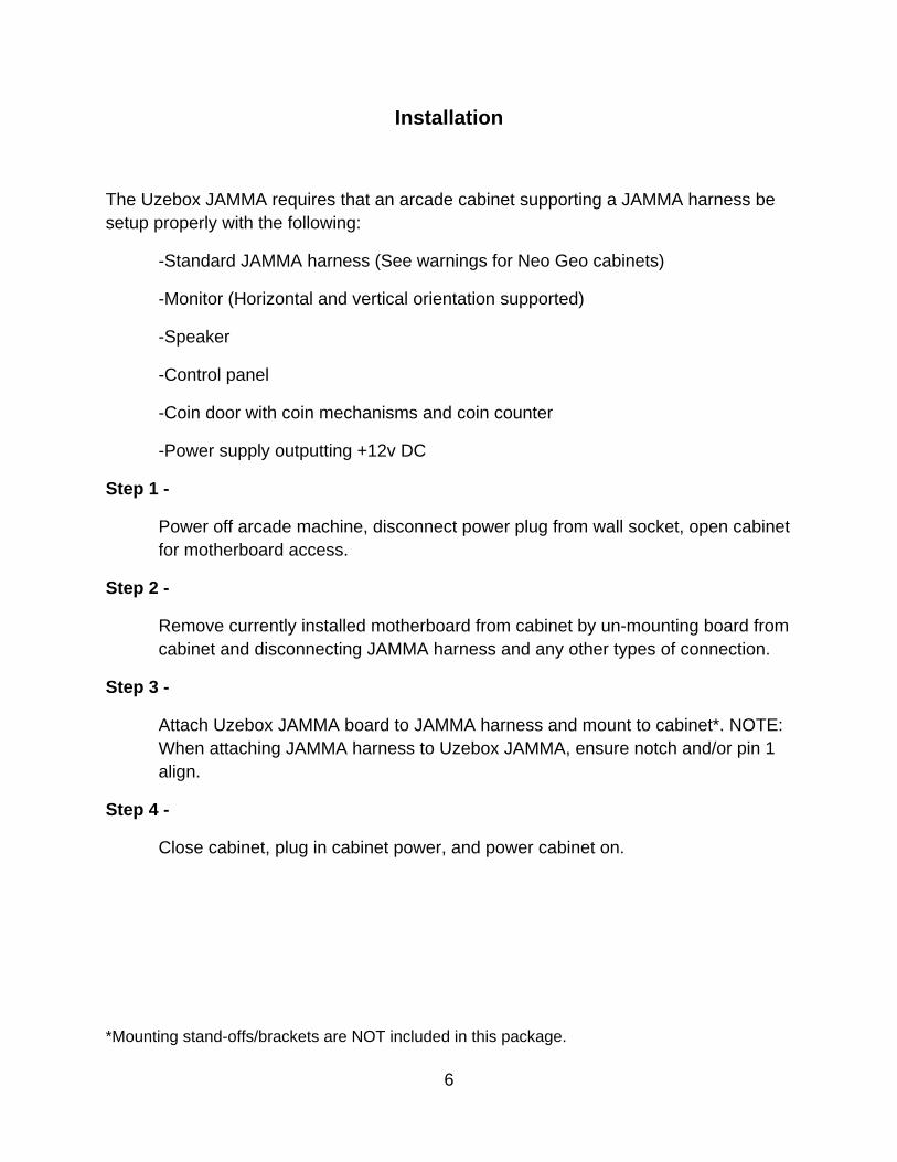
Volume adjustment
Volume is adjusted via R13 by rotating the potentiometer. Rotating R13 clockwise increases the volume, while rotating counter-clockwise decreases volume.
(Volume adjustment. Rotating clockwise increases volume)
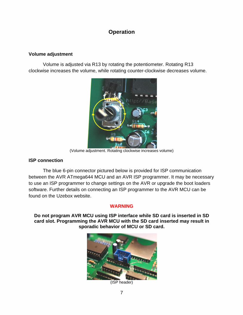
ISP connection
The blue 6-pin connector pictured below is provided for ISP communication between the AVR ATmega644 MCU and an AVR ISP programmer. It may be necessary to use an ISP programmer to change settings on the AVR or upgrade the boot loaders software. Further details on connecting an ISP programmer to the AVR MCU can be found on the Uzebox website.
WARNING
Do not program AVR MCU using ISP interface while SD card is inserted in SD card slot. Programming the AVR MCU with the SD card inserted may result in
sporadic behavior of MCU or SD card.
(ISP header)
7
SD card
The Uzebox JAMMA utilizes SD card storage to load games. Before any SD card can be used, the card must be formatted to FAT16 with no fragmentation. When downloading games to the SD card, it is recommended that each file be copied individually to prevent fragmentation. If fragmentation occurs, the Uzebox boot loader may not be able to recognize the SD card, not recognize games, or fail to load games. The Uzebox boot loader software at the moment is only able to recognize 128 different ".uze" files. All files must be kept inside the root directory of the SD card.
Once games are downloaded onto the SD card, insert the SD card into the Uzebox JAMMA SD card slot. Power the device on, and the boot loader should show the games currently on the SD card. The SD card may be removed during a games operation* as long as the game does not require any resources on the SD card.
(SD card socket)
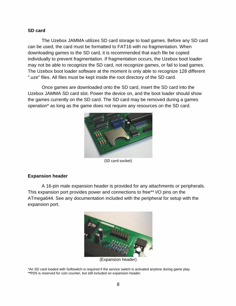
Expansion header
A 16-pin male expansion header is provided for any attachments or peripherals. This expansion port provides power and connections to free** I/O pins on the ATmega644. See any documentation included with the peripheral for setup with the expansion port.
(Expansion header)
*An SD card loaded with Softswitch is required if the service switch is activated anytime during game play. **PD5 is reserved for coin counter, but still included on expansion header.
8
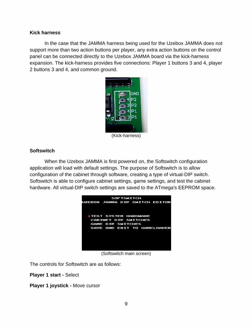
Kick harness
In the case that the JAMMA harness being used for the Uzebox JAMMA does not support more than two action buttons per player, any extra action buttons on the control panel can be connected directly to the Uzebox JAMMA board via the kick-harness expansion. The kick-harness provides five connections: Player 1 buttons 3 and 4, player 2 buttons 3 and 4, and common ground.
(Kick-harness)
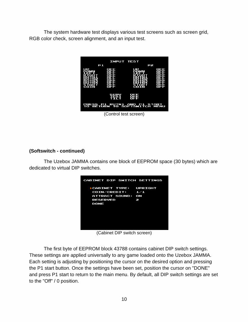
Softswitch
When the Uzebox JAMMA is first powered on, the Softswitch configuration application will load with default settings. The purpose of Softswitch is to allow configuration of the cabinet through software, creating a type of virtual-DIP switch. Softswitch is able to configure cabinet settings, game settings, and test the cabinet hardware. All virtual-DIP switch settings are saved to the ATmega's EEPROM space.
(Softswitch main screen)
The controls for Softswitch are as follows:
Player 1 start - Select
Player 1 joystick - Move cursor
9
The system hardware test displays various test screens such as screen grid, RGB color check, screen alignment, and an input test.
(Control test screen)
(Softswitch - continued)
The Uzebox JAMMA contains one block of EEPROM space (30 bytes) which are dedicated to virtual DIP switches.
(Cabinet DIP switch screen)
The first byte of EEPROM block 43788 contains cabinet DIP switch settings. These settings are applied universally to any game loaded onto the Uzebox JAMMA. Each setting is adjusting by positioning the cursor on the desired option and pressing the P1 start button. Once the settings have been set, position the cursor on "DONE" and press P1 start to return to the main menu. By default, all DIP switch settings are set to the "Off" / 0 position.
10
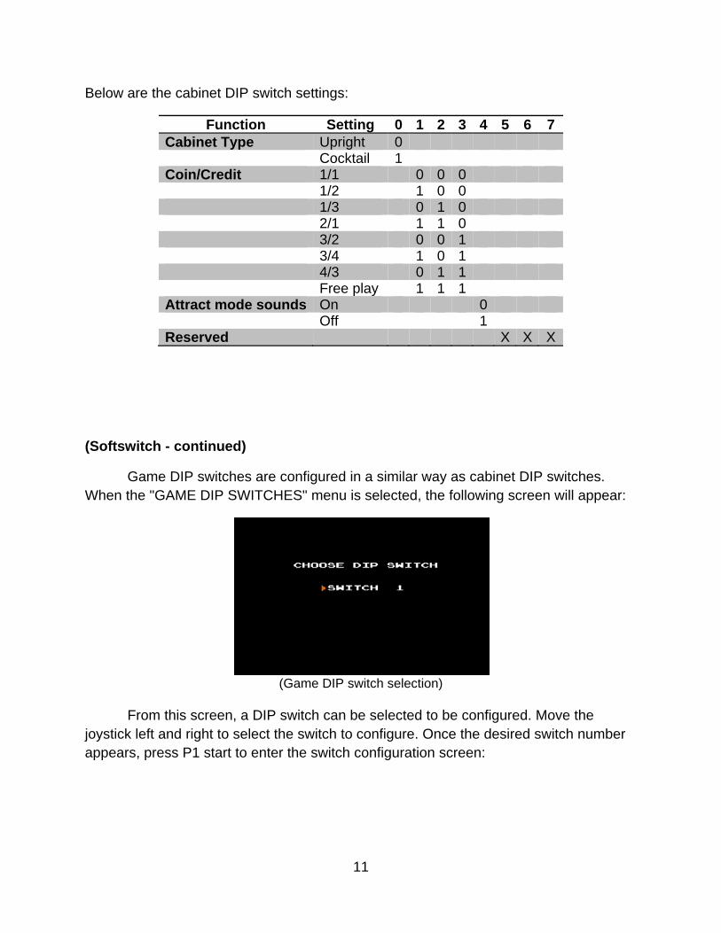
Below are the cabinet DIP switch settings:
Function Setting 0 1 2 3 4 5 6 7 Cabinet Type Upright 0 Cocktail 1 Coin/Credit 1/1 0 0 0 1/2 1 0 0 1/3 0 1 0 2/1 1 1 0 3/2 0 0 1 3/4 1 0 1 4/3 0 1 1 Free play 1 1 1 Attract mode sounds On 0 Off 1 Reserved X X X
(Softswitch - continued)
Game DIP switches are configured in a similar way as cabinet DIP switches. When the "GAME DIP SWITCHES" menu is selected, the following screen will appear:
(Game DIP switch selection)
From this screen, a DIP switch can be selected to be configured. Move the joystick left and right to select the switch to configure. Once the desired switch number appears, press P1 start to enter the switch configuration screen:
11
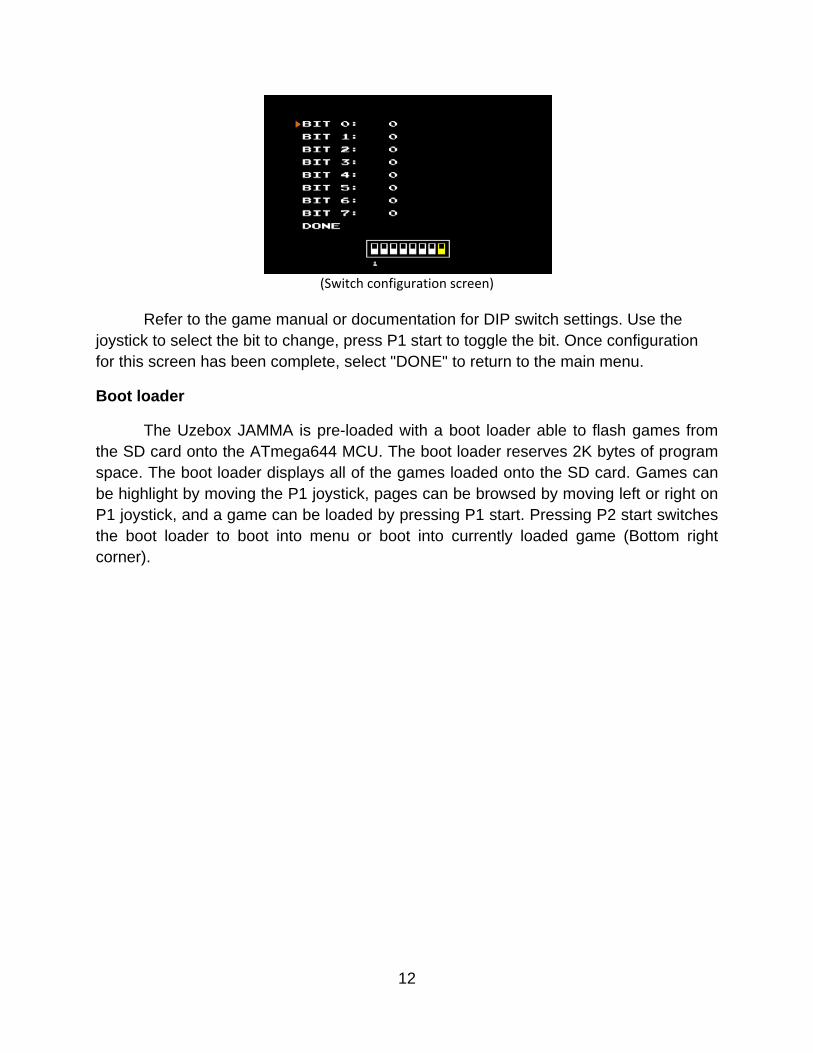
(Switch configuration screen)
Refer to the game manual or documentation for DIP switch settings. Use the joystick to select the bit to change, press P1 start to toggle the bit. Once configuration for this screen has been complete, select "DONE" to return to the main menu.
Boot loader
The Uzebox JAMMA is pre-loaded with a boot loader able to flash games from the SD card onto the ATmega644 MCU. The boot loader reserves 2K bytes of program space. The boot loader displays all of the games loaded onto the SD card. Games can be highlight by moving the P1 joystick, pages can be browsed by moving left or right on P1 joystick, and a game can be loaded by pressing P1 start. Pressing P2 start switches the boot loader to boot into menu or boot into currently loaded game (Bottom right corner).
12
Troubleshooting
General
No video, no sound
-Power supply not receiving power. Plug-in cabinet and switch on power.
-Ensure that the Uzebox JAMMA is seated properly in the harness edge connector.
-Program/game failed to load properly from SD card. Enter the boot loader menu by holding any of the player pushbuttons while powering on/restarting cabinet and re-select game.
-Test inputs and outputs on the LM7805 voltage regulator. Replace LM7805 if component fails to output around 5v DC.
-Check any fuses on cabinet. Replace fuses if broken.
SD card not being read or not being read properly
-Ensure the SD card is formatted properly (FAT16) and is loaded with games/programs
-The SD card is not seated properly inside SD card socket. Push SD card into socket until a "click" sound is heard. Push again to release if necessary.
-The microcontroller's SPI interface may be disabled or malfunctioning, replace AVR microcontroller.
-The LM2937 voltage regulator supplying power to the SD card may be malfunctioning. Test inputs and outputs on LM2937. Replace LM2937 if component fails output around 3.3v DC.
-The step down resistor circuit may be malfunctioning or damaged. Check board for any shorts or damage in the resistor circuit.
-The SD card being used is not compatible with the Uzebox JAMMA.
Video
No video
-Monitor is not powered on. Ensure CRT is wired correctly.
-Monitor does not support the Uzebox JAMMA.
13
(No video - continued)
-Uzebox JAMMA is not generating video. Check outputs on red, green, blue, and sync outputs
"Checkerboard"/noisy video output
-Control circuits are not being powered. Ensure 4021 ICs are receiving power.
Image colors are inverted
-The monitor being used inverts the video signals. Change settings on monitor or swap monitor.
Weird colors, missing colors, color haze
-Color resistor circuit is shorting. Ensure resistors R1-R8 are not damaged or shorting.
-JTAG fuse on AVR is still enabled causing some pins on video output port to act as inputs or data transmission outputs. Disable JTAG fuse.
-Monitor may be malfunctioning or monitor adjustments may be set improperly.
Audio
No sound
-Volume adjustment is set too low. Rotate volume adjustment clockwise until sound can be heard.
-LM386 audio amplifier may be malfunctioning or damaged. Ensure amplifier circuit is receiving power. Replace LM386 amplifier IC.
-Speaker is not connected to harness. Ensure speaker is connected to harness.
Sound output is "scratchy"
-Volume adjustment is too high. Rotate volume adjustment counter-clockwise until audio is clear.
Controls
No control input
-Devices on control panel are no connected to common ground. Ensure all pushbuttons, joysticks, or any other input mechanisms are connected to a common ground.
14
(Controls - continued)
-The control circuits are not transmitting data, clocking, or latching. Ensure connection between control circuits and AVR microcontroller is not broken. Run a known working compatible game/program to ensure inputs work. Replace AVR microcontroller.
-Currently loaded program may not support Uzebox JAMMA.
If this troubleshooting documentation has not helped in resolving any problems being experienced when using the Uzebox JAMMA, visit the Uzebox forums (http://Uzebox.org/forums)
15

16
Contact
Any questions, comments, concerns can be emailed to Basement Hobbies at the following email address: [email protected]
For other projects and news visit: http://BasementHobbies.wordpress.com
For further documentation and support on the Uzebox Project visit: http://uzebox.org Forums: http://uzebox.org/forums