uvm configuration tool quick start guide - triatek · uvm configuration tool quick start guide for...
TRANSCRIPT

UVM Configuration ToolQuick Start GuideFor Typical Valve Installations
www.triatek.com │[email protected] │Ph: 770-242-1922 │4487 Park Drive Suite A-2 Norcross, GA 30093 │ v.052016
1. Click the Get All Settings From Device button on the Misc Tab.
2. Wait until the process finishes (button re-enables), and click the Save Displayed Values to File button. Follow the File Save dialog and give the information a file name to save as.
This Universal Valve Module (UVM) Quick Start Guide assumes that the UVM Configuration Tool has been previously installed, the communications channel has been set up, and the UVM is powered and ready to be used. Refer to the UVM Configuration Tool Manual if you need additional help beyond this quick start guide, or to reach Triatek’s customer service email [email protected] or call 770-242-1922.
www.triatek.com │[email protected] │Ph: 770-242-1922 │4487 Park Drive Suite A-2 Norcross, GA 30093 │ v.052016
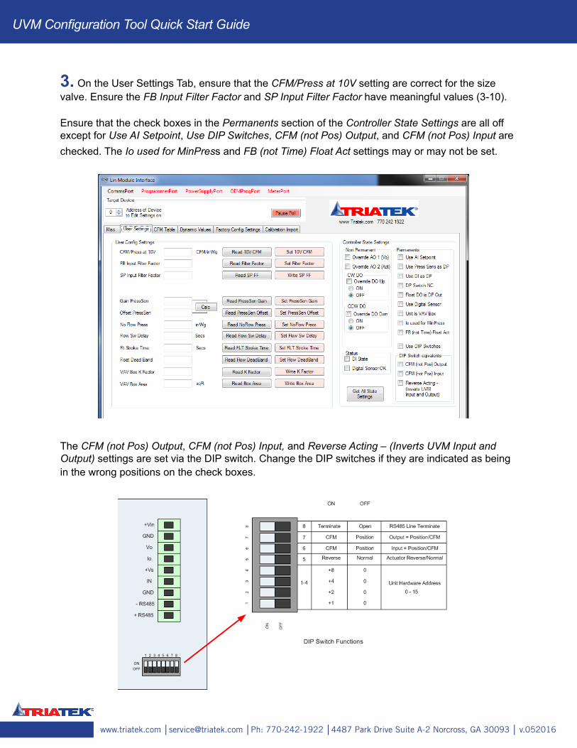
3. On the User Settings Tab, ensure that the CFM/Press at 10V setting are correct for the size valve. Ensure the FB Input Filter Factor and SP Input Filter Factor have meaningful values (3-10).
Ensure that the check boxes in the Permanents section of the Controller State Settings are all off except for Use AI Setpoint, Use DIP Switches, CFM (not Pos) Output, and CFM (not Pos) Input are checked. The Io used for MinPress and FB (not Time) Float Act settings may or may not be set.
The CFM (not Pos) Output, CFM (not Pos) Input, and Reverse Acting – (Inverts UVM Input and Output) settings are set via the DIP switch. Change the DIP switches if they are indicated as being in the wrong positions on the check boxes.
UVM Configuration Tool Quick Start Guide

www.triatek.com │[email protected] │Ph: 770-242-1922 │4487 Park Drive Suite A-2 Norcross, GA 30093 │ v.052016
4. The Reverse Acting –(Inverts UVM Input and Output) needs to match the actuator and controller setting.
Normal Acting (typically supply) require the UVM to be set to Normal, the actuator set to Normal and the controller output to be Normal.
Reverse Acting (typically exhausts and hoods) require the UVM to be set to Reverse, the actuator set to Reverse and the controller output to be Reverse.
UVM Configuration Tool Quick Start Guide
www.triatek.com │[email protected] │Ph: 770-242-1922 │4487 Park Drive Suite A-2 Norcross, GA 30093 │ v.052016
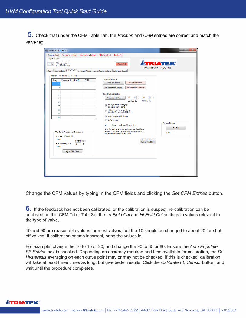
5. Check that under the CFM Table Tab, the Position and CFM entries are correct and match the valve tag.
Change the CFM values by typing in the CFM fields and clicking the Set CFM Entries button.
6. If the feedback has not been calibrated, or the calibration is suspect, re-calibration can be achieved on this CFM Table Tab. Set the Lo Field Cal and Hi Field Cal settings to values relevant to the type of valve.
10 and 90 are reasonable values for most valves, but the 10 should be changed to about 20 for shut-off valves. If calibration seems incorrect, bring the values in.
For example, change the 10 to 15 or 20, and change the 90 to 85 or 80. Ensure the Auto Populate FB Entries box is checked. Depending on accuracy required and time available for calibration, the Do Hysteresis averaging on each curve point may or may not be checked. If this is checked, calibration will take at least three times as long, but give better results. Click the Calibrate FB Sensor button, and wait until the procedure completes.
UVM Configuration Tool Quick Start Guide
www.triatek.com │[email protected] │Ph: 770-242-1922 │4487 Park Drive Suite A-2 Norcross, GA 30093 │ v.052016
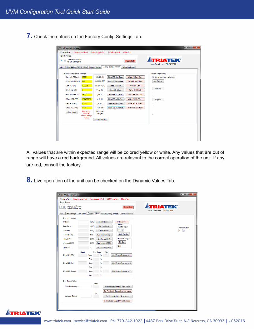
7. Check the entries on the Factory Config Settings Tab.
All values that are within expected range will be colored yellow or white. Any values that are out of range will have a red background. All values are relevant to the correct operation of the unit. If any are red, consult the factory.
8. Live operation of the unit can be checked on the Dynamic Values Tab.
UVM Configuration Tool Quick Start Guide
UVM Configuration Tool Quick Start Guide
www.triatek.com │[email protected] │Ph: 770-242-1922 │4487 Park Drive Suite A-2 Norcross, GA 30093 │ v.052016
Information like the current computed CFM, actual A/D counts in and out can be viewed here. If processes like calibration do not perform correctly, check the FB A/D count here (Raw AI 0 (Fb). If this value does not change when the valve moves, there is potentially a problem with the FB sensor mechanical or electrical connections.
The AOs can also be controlled from here. Go to the User Tab and override AO1 or AO2 or both. On the Dynamic Values Tab enter the % position (x10) ie 25% = 250, on the Actuator Output or Feedback Output field and then click the Set Actuator Output Value or Set Feedback Output Value buttons.
Refer to the UVM Configuration Tool Manual if you need additional help beyond this quick start guide, or to reach Triatek’s customer service email [email protected] or call 770-242-1922.