utm, mgrs and the us national grid - central war
TRANSCRIPT

UTM, MGRS and the US National GridThe Military Grid Referencing System (MGRS) has been around since World War II and continues to be the military standard. MGRS and the USNG (US National Grid) use the long-standing Universal Transverse Mercator (UTM) projection and coordinate systems, with a different notation to make it easier and more consistent to use and communicate.
UTM divides the surface of the earth into “rectangular” zones of 6 degrees of longitude (from pole to pole) and 8 degrees of latitude. Each of these zones is then given a unique alphanumeric identifier. We are currently in zone 15S.
S does NOT mean south. It’s just a letter. North of us is 15T, west is 14S.
UTM refers to locations as a distance in meters from the lower-left corner of the zone. However, this is a lot of digits, requires full-resolution (1 meter accuracy) and there are usually more digits one way than the other.

MGRS simplfies this, first by dividing zones into 100,000-meter “squares,” each given a two-character designation formed by rows and columns of single characters. We are currently in square UD.
Then, this makes your life really easy by having only five digits each direction to specify anywhere within the grid to 1 meter precision. By convention, and because you always know how many digits, it’s also possible to use fewer. Conventional “grid reference” means you are designating a location with 1000 meter precision, and that only takes 4 digits. Anywhere in the world can be refereced with just a few letters and numbers:
Right here we’re at 15S UD 31204 87833
Taking the Easting:
3 10,000 m precision
1 1,000
2 100
0 10
4 1
Note that you don’t need the zone or square for most communications. If you are working with others inside your square, or with people who know approximately where you are, you can just use the numbers (4063) alone.
(I like to give a little pause between the Easting and Northing, and write them down with a gap but that’s just me, and is not convention per se.)
You do need to pay attention to this, however. You might be operating right next to people, but on the edge of a zone. But when possible, eliminate extra information. Especially when communicating on the radio, this is good policy, good security, and much faster.
UD
15S
100,000 M SQUAREIDENTIFICATION
GRID ZONE DESIGNATION
SAMPLE 1000 METER GRID SQUARE
Samplepoint
12 1345
46100 METER REFERENCE
WHEN REPORTING OUTSIDE THE 100,000 METER SQUARE AREA IN WHICH THE POINT LIES, PREFIX THE 100,000 METER SQUARE IDENTIFICATION.
Example: WD123456
WHEN REPORTING OUTSIDE THE G RID ZONE DESIGNATION AREA I N WHICH THE POINT LIES, PREFIX THE GRID ZONE DESIGNATION.
Example: 15SWE123456
1. Read large numbers labeling the VERTICAL grid line left of t he p oint a nd e stimate tenths ( 100 meters) from gridline to point. 123
2. Read large numbers labeling the HORIZONTAL grid l ine below the point and estimate t enths (100 meters) f rom gridline to point. 456
Example: 123456
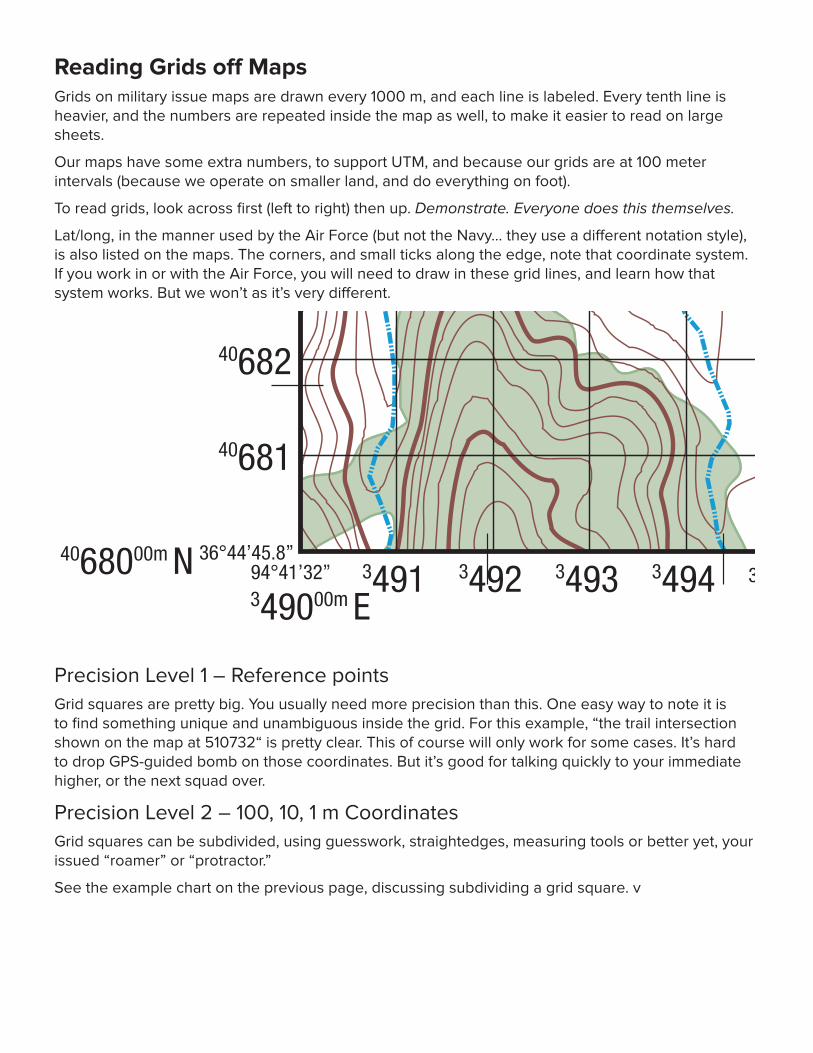
Reading Grids off MapsGrids on military issue maps are drawn every 1000 m, and each line is labeled. Every tenth line is heavier, and the numbers are repeated inside the map as well, to make it easier to read on large sheets.
Our maps have some extra numbers, to support UTM, and because our grids are at 100 meter intervals (because we operate on smaller land, and do everything on foot).
To read grids, look across first (left to right) then up. Demonstrate. Everyone does this themselves.
Lat/long, in the manner used by the Air Force (but not the Navy... they use a different notation style), is also listed on the maps. The corners, and small ticks along the edge, note that coordinate system. If you work in or with the Air Force, you will need to draw in these grid lines, and learn how that system works. But we won’t as it’s very different.
Precision Level 1 – Reference pointsGrid squares are pretty big. You usually need more precision than this. One easy way to note it is to find something unique and unambiguous inside the grid. For this example, “the trail intersection shown on the map at 510732“ is pretty clear. This of course will only work for some cases. It’s hard to drop GPS-guided bomb on those coordinates. But it’s good for talking quickly to your immediate higher, or the next squad over.
Precision Level 2 – 100, 10, 1 m CoordinatesGrid squares can be subdivided, using guesswork, straightedges, measuring tools or better yet, your issued “roamer” or “protractor.”
See the example chart on the previous page, discussing subdividing a grid square. v
LIMIT OF OPERATIONS AREA
LIMIT OF OPERATIONS AREA
LIMIT OF OPERATIONS AREA
LIMIT OF OPERATIONS AREALIMIT OF OPERATIONS AREA
LIMIT OF OPERATIONS AREALIMIT OF OPERATIONS AREA
LIMIT OF OPERATIONS AREA
LIM
IT O
F O
PE
RAT
ION
S A
RE
A
LIM
IT O
F O
PE
RAT
ION
S A
RE
A
LIM
IT O
F O
PE
RAT
ION
S A
RE
A
4068000m N
350000m E 351000m E349000m E
500
500
500
510
510
510
4069000m N
4068000m N
4069000m N
352000m E
700700700
690690690
500 510
4071000m N
4070000m N
4071000m N
4070000m N
710710710
350000m E 351000m E 352000m E
4072000m N
349000m E
4072000m N
94°39’35.5”94°40’94°41’
94°41’32”
94°39’32.3”
94°41’
94°41’30.06”
94°40’
36°46’
36°45’
36°46’56.1”
36°44’45.8”
36°46’
36°45’
36°46’55.8”
36°44’43.9”
3501 3502 3503 3504 3505 3506 3507 3508 3509 3511 3512 3513 3514 3515 3516 3517 3518 3519349934983497349634953494349334923491
3501 3502 3503 3504 3505 3506 3507 3508 3509 3511 3512 3513 3514 3515 3516 3517 3518 3519349934983497349634953494349334923491
40719
40718
40717
40716
40715
40714
40713
40712
40711
40709
40708
40707
40706
40705
40704
40703
40702
40701
40699
40698
40697
40696
40695
40694
40693
40692
40691
40689
40688
40687
40686
40685
40684
40683
40682
40681
40719
40718
40717
40716
40715
40714
40713
40712
40711
40709
40708
40707
40706
40705
40704
40703
40702
40701
40699
40698
40697
40696
40695
40694
40693
40692
40691
40689
40688
40687
40686
40685
40684
40683
40682
40681
HELIPORTEDAP/5/S
1020
BSDDAP
Drava
Loange
LUCALA
KASAI
CALABAR
Vehlefanz
Destroyed
22
231 23
25
20
21
19
17
17
27
15
27
201
171
18
183
181
182
19
19
176
19
Nibelungenalle
17
17173
176B
25
29
29
25
34
R49
R49
34
R49
36
36
29
29
R49
28281
22
22
28
30
15
15
15
R49
15W15E
CONTOUR INTERVAL 10 FEET
Scale 1:7,500
ROADS
Secondary all weather,hard surface, two or more lanes wide
Light duty, all weather, improved surface
Light duty, seasonal, unimproved surface
Trail or unimproved surface road
Route markers: State highway
BOUNDARIES
Reservation: military operations area
Fenceline
Power transmission line
Occupied permanent dwellings
Unoccupied buildings or structures
Horizontal control station
Bench mark, monumented
Bench mark, non-monumented
Spot elevations in feet: checked; unchecked
Woodland
Vineyard; Orchard
Pond
Intermittent pond or lake
Intermittent stream
Unclassified stream
792
817
BM
LIMIT OF OPERA
SPHEROID . . . . . . . . . . . . . . . . . . . . . . . . . . . . . . . . . . . . . . . . . . . . . . . . . . . . CLARKE 1866GRID . . . . . . . . . . . . . . . . . . . . . . . . . . . . . . . . . . . . . . . . . . . . . . . . . . . . 100 M UTM ZONE 15PROJECTION . . . . . . . . . . . . . . . . . . . . . . . . . . . . . . . . . . . . . . . TRANSVERSE MERCATORVERTICAL DATUM . . . . . . . . . . . . . NATIONAL GEODETIC VERTICAL DATUM OF 1929HORIZONTAL DATUM . . . . . . . . . . . . . . . . . . . . . . . . . . . WORLD GEODETIC SYSTEM 84CONTROL BY . . . . . . . . . . . . . . . . . . . . . . . . . . . . . . . . . . . . . . . . . . USGS, USC&GS & DMAPREPARED BY . . . . . . . . . . . . . . . . . . . . . . . . . . . . . . . . . . . . . . . . . . . . . . KCAA GIS AUTHPRINTED BY . . . . . . . . . . DEFENSE MAPPING AGENCY TOPOGRAPHIC CENTER 7 84
UA
15S
100,000 M SQUAREIDENTIFICATION
GRID ZONE DESIGNATION
SAMPLE 1000 METER GRID SQUARE
Samplepoint
12 1345
46100 METER REFERENCE
WHEN REPORTING OUTSIDE THE 100,000 METER SQUARE AREA IN WHICH THE POINT LIES, PREFIX THE 100,000 METER SQUARE IDENTIFICATION.
Example: WD123456
WHEN REPORTING OUTSIDE THE GRID ZONE DESIGNATION AREA IN WHICH THE POINT LIES, PREFIX THE GRID ZONE DESIGNATION.
Example: 15SWE123456
1. Read large numbers labeling the VERTICAL grid line left of the point and estimate tenths (100 meters) from gridline to point. 123
2. Read large numbers labeling the HORIZONTAL grid line below the point and estimate tenths (100 meters) from gridline to point. 456
Example: 123456
GN
TO CONVERT A MAGNETIC
AZIMUTH TO A GRID AZIMUTH SUBTRACT G-M
ANGLE
TO CONVERT A GRID AZIMUTH TO
A MAGNETIC AZIMUTH ADD G-M ANGLE
2008G-M ANGLE
1°1’ (18 MILS)
GRID CONVERGENCE 2°39’ (47 MILS) FOR CENTER OF
SHEET
0 100 200 300 400 500 Meters100 500
0 100 200 300 400 500 Yards100 500
0 1/8 1/4 Statute Mile
EAST MAROS EDITION 6–DMA SERIES V734 SHEET 2013 IIIARDEA 1:7,500
THIS MAP IS RED-LIGHT READABLE
DMA STOCK NO. V7781X21546 ED.NO. 021EDITION 6–DMA SERIES V734 SHEET 2013 III
One second of longitude equals 24.36 mUnlabeled ticks are 10 second increments
LEGENDCOMPILED IN 1978 FROM BEST AVAILABLE SOURCES
ON THIS MAP, A LANE IS GENERALLY CONSIDERED AS BEING A MINIMUM OF 2.5 METERS (8 FEET) IN WIDTH
Prepared and published by the Defense Mapping AgencyTopographic Center, Bethesda, MD.
ELEVATION GUIDE
High
Medium
Low
ADJOINING SHEETS
2013 III1913 II 2013 II
2012 IV 2012 I1912 I
2013 IV 2013 I1913 I
E 813 725
One
sec
ond
of l
atitu
de
equa
ls 3
1.3
m
One
sec
ond
of l
atitu
de
equa
ls 3
1.3
m
TRUE NORTH
GRID NORTH
MAG
NETI
C NO
RTH

DeclinationDeclination is a complexity induced upon you because our north-seeking device doesn’t work off Grid north, the lines where our MGRS GRID is aligned, but off magnetic north.
The magnetic north pole wanders about, and as a result of the geometry of trying to represent the round earth on flat maps.
Luckily, you don’t have to do the math, and every military map (and many others) has a declination chart in the corner, giving you the numbers. There are several kinds: USGS and U.S. military maps are to (angular) scale and aligned with a grid line, others (e.g. Russian) are not. The sample here is a U.S. Military one.
To adjust, put the compass on the map, aligned with GN. Twist the capsule (or declination adjustment) so the capsule aligns with MN.
GN is Grid North, or the north/south axis against which all the lines in the UTM Zone grid are aligned. These are different for each Zone or map sheet, so read your map each time.
TN is True North. This is often marked with a star, and points to the location where all the longitude lines converge at the North Pole (which is more or less the axis about which the earth spins). This is the “grid” upon which lat/long measurements are taken. If using lat/long – like if you are working with the USAF – you will need to adjust directions to True North, not Grid North. But we do not care about True North.
MN is Magnetic North, (often marked with an arrow) and corresponds to where your compass points. The declination chart is accurate ONLY at one point. Sometimes this is the center of the Zone, but for military charts it tends to be at the center of the sheet, or the actual piece of paper you are issued. This often will not matter a lot, but if you are working somewhere with 80° declination, it will change by several degrees as you move across sheets; driving for an hour can change declination a great deal.
Magnetic north moves about all the time. You need to look for the date the map was published; sometimes the date is immediately adjacent to the declination scale for this exact reason. In high declination areas, it can put you off by miles, even when traveling by foot, after just a few years.
In general, it’s good to remember that Zones simulate being flat, 2D sheets so the grids are all square. But this is a cheat so there is some inaccuracy, and projection inaccuracy gets more severe as you approach the poles. If you will be operating in arctic areas, try to get familiar with the navigation methods needed in such environments.

LIMIT OF OPERATIONS AREA
LIMIT OF OPERATIONS AREA
LIMIT OF OPERATIONS AREA
LIMIT OF OPERATIONS AREALIMIT OF OPERATIONS AREA
LIMIT OF OPERATIONS AREALIMIT OF OPERATIONS AREA
LIMIT OF OPERATIONS AREA
LIM
IT O
F O
PE
RAT
ION
S A
RE
A
LIM
IT O
F O
PE
RAT
ION
S A
RE
A
LIM
IT O
F O
PE
RAT
ION
S A
RE
A
4068000m N
350000m E 351000m E349000m E
500
500
500
510
510
510
4069000m N
4068000m N
4069000m N
352000m E
700700700
690690690
500 510
4071000m N
4070000m N
4071000m N
4070000m N
710710710
350000m E 351000m E 352000m E
4072000m N
349000m E
4072000m N
94°39’35.5”94°40’94°41’
94°41’32”
94°39’32.3”
94°41’
94°41’30.06”
94°40’
36°46’
36°45’
36°46’56.1”
36°44’45.8”
36°46’
36°45’
36°46’55.8”
36°44’43.9”
3501 3502 3503 3504 3505 3506 3507 3508 3509 3511 3512 3513 3514 3515 3516 3517 3518 3519349934983497349634953494349334923491
3501 3502 3503 3504 3505 3506 3507 3508 3509 3511 3512 3513 3514 3515 3516 3517 3518 3519349934983497349634953494349334923491
40719
40718
40717
40716
40715
40714
40713
40712
40711
40709
40708
40707
40706
40705
40704
40703
40702
40701
40699
40698
40697
40696
40695
40694
40693
40692
40691
40689
40688
40687
40686
40685
40684
40683
40682
40681
40719
40718
40717
40716
40715
40714
40713
40712
40711
40709
40708
40707
40706
40705
40704
40703
40702
40701
40699
40698
40697
40696
40695
40694
40693
40692
40691
40689
40688
40687
40686
40685
40684
40683
40682
40681
HELIPORTEDAP/5/S
1020
BSDDAP
Drava
Loange
LUCALA
KASAI
CALABAR
Vehlefanz
Destroyed
22
231 23
25
20
21
19
17
17
27
15
27
201
171
18
183
181
182
19
19
176
19
Nibelungenalle
17
17173
176B
25
29
29
25
34
R49
R49
34
R49
36
36
29
29
R49
28281
22
22
28
30
15
15
15
R49
15W15E
CONTOUR INTERVAL 10 FEET
Scale 1:7,500
ROADS
Secondary all weather,hard surface, two or more lanes wide
Light duty, all weather, improved surface
Light duty, seasonal, unimproved surface
Trail or unimproved surface road
Route markers: State highway
BOUNDARIES
Reservation: military operations area
Fenceline
Power transmission line
Occupied permanent dwellings
Unoccupied buildings or structures
Horizontal control station
Bench mark, monumented
Bench mark, non-monumented
Spot elevations in feet: checked; unchecked
Woodland
Vineyard; Orchard
Pond
Intermittent pond or lake
Intermittent stream
Unclassified stream
792
817
BM
LIMIT OF OPERA
SPHEROID . . . . . . . . . . . . . . . . . . . . . . . . . . . . . . . . . . . . . . . . . . . . . . . . . . . . CLARKE 1866GRID . . . . . . . . . . . . . . . . . . . . . . . . . . . . . . . . . . . . . . . . . . . . . . . . . . . . 100 M UTM ZONE 15PROJECTION . . . . . . . . . . . . . . . . . . . . . . . . . . . . . . . . . . . . . . . TRANSVERSE MERCATORVERTICAL DATUM . . . . . . . . . . . . . NATIONAL GEODETIC VERTICAL DATUM OF 1929HORIZONTAL DATUM . . . . . . . . . . . . . . . . . . . . . . . . . . . WORLD GEODETIC SYSTEM 84CONTROL BY . . . . . . . . . . . . . . . . . . . . . . . . . . . . . . . . . . . . . . . . . . USGS, USC&GS & DMAPREPARED BY . . . . . . . . . . . . . . . . . . . . . . . . . . . . . . . . . . . . . . . . . . . . . . KCAA GIS AUTHPRINTED BY . . . . . . . . . . DEFENSE MAPPING AGENCY TOPOGRAPHIC CENTER 7 84
UA
15S
100,000 M SQUAREIDENTIFICATION
GRID ZONE DESIGNATION
SAMPLE 1000 METER GRID SQUARE
Samplepoint
12 1345
46100 METER REFERENCE
WHEN REPORTING OUTSIDE THE 100,000 METER SQUARE AREA IN WHICH THE POINT LIES, PREFIX THE 100,000 METER SQUARE IDENTIFICATION.
Example: WD123456
WHEN REPORTING OUTSIDE THE GRID ZONE DESIGNATION AREA IN WHICH THE POINT LIES, PREFIX THE GRID ZONE DESIGNATION.
Example: 15SWE123456
1. Read large numbers labeling the VERTICAL grid line left of the point and estimate tenths (100 meters) from gridline to point. 123
2. Read large numbers labeling the HORIZONTAL grid line below the point and estimate tenths (100 meters) from gridline to point. 456
Example: 123456
GN
TO CONVERT A MAGNETIC
AZIMUTH TO A GRID AZIMUTH SUBTRACT G-M
ANGLE
TO CONVERT A GRID AZIMUTH TO
A MAGNETIC AZIMUTH ADD G-M ANGLE
2008G-M ANGLE
1°1’ (18 MILS)
GRID CONVERGENCE 2°39’ (47 MILS) FOR CENTER OF
SHEET
0 100 200 300 400 500 Meters100 500
0 100 200 300 400 500 Yards100 500
0 1/8 1/4 Statute Mile
EAST MAROS EDITION 6–DMA SERIES V734 SHEET 2013 IIIARDEA 1:7,500
THIS MAP IS RED-LIGHT READABLE
DMA STOCK NO. V7781X21546 ED.NO. 021EDITION 6–DMA SERIES V734 SHEET 2013 III
One second of longitude equals 24.36 mUnlabeled ticks are 10 second increments
LEGENDCOMPILED IN 1978 FROM BEST AVAILABLE SOURCES
ON THIS MAP, A LANE IS GENERALLY CONSIDERED AS BEING A MINIMUM OF 2.5 METERS (8 FEET) IN WIDTH
Prepared and published by the Defense Mapping AgencyTopographic Center, Bethesda, MD.
ELEVATION GUIDE
High
Medium
Low
ADJOINING SHEETS
2013 III1913 II 2013 II
2012 IV 2012 I1912 I
2013 IV 2013 I1913 I
E 813 725
One
sec
ond
of l
atitu
de
equa
ls 3
1.3
m
One
sec
ond
of l
atitu
de
equa
ls 3
1.3
m
TRUE NORTH
GRID NORTH
MAG
NETI
C NO
RTH