utilizing yarnell’s flow data to validate & analyze cfd models
TRANSCRIPT

Utilizing Yarnell’s Flow Data to Validate & Analyze CFD Models
Alexander Mann Hydrologist, Surface Water Resources Division
Maine Department of Transportation Environmental Office 16 State House Station
Augusta, Maine 04333-0016 Ph. 207-215-6328 [email protected]

Acknowledgements
David Yarnell (d. 1937), USDA and University of Iowa Hydraulics Lab
Dr. Kornel Kerenyi, FHWA Turner Fairbanks Hydraulics Lab
Dr. Steve Lottes, Transportation Research and Analysis Computing Center
Dr. Charles Hebson, Chief Hydrologist. Maine Dept. of Transportation

Initial Concept: Increase Capacity and Reduce Outlet Losses in Highway Culverts, Like Draft Tubes in Hydropower
Good Sources of Published Data? What Concepts Are Involved? How Would the Available Physical Model Data be Compared to the CFD Model? Photo: Yarnell’s 5’ long D = 18” to 26” Diffuser outlet from his 1926 book “The Flow of Water Through Culverts”
Validation of an Outlet Diffuser CFD Model

What is a Diffuser and How Does it Function?
This Venturi Meter displays the basic concept.
Pressure Recovery
Source: Wermac.org

Yarnell’s Model – In this case a 3’ by 3’ box transitioning into a 6’W by 3’H Outlet Diffuser
Large Physical Presence Temporary Difficult to Share
Physical Models
Real Data Point Data Traditional Sensors _ Piezometers and Pitot Tubes
Photo curtesy of Connie Mutel, at the University of Iowa Hydraulics Lab

Sources for Physical Diffuser Model Data
The Flow of Water Through Culverts, Yarnell 1926 Pipes, Box Culverts, and Diffusers (“Increasers”)
Effect of Flared Outlets on Discharge of Box Culverts, Venega 1950 Effect of flare angle on discharge of box culverts.
Effect of Length on Performance Characteristics of Diffusers, Smith 1951 Effect of diffuser length on discharge of box culverts.

Important Concepts Pressure Recovery: Pressure - Velocity Relationship
Pd-Pp = (ρ/2)(Vp2 – Vd
2)
Outlet Losses: Borda-Carnot Derivation (Tullis 2012) Ho=ko(Vp-Vc)2/2g where ko=(1-Ap/Ac)2
Effect of Outlet Shape on Pipe Capacity Streamlined Flow:
Flume and Syphon Transitions (Hinds 1927) Minimum Energy Culverts (McKay 1971)
Pipe Roughness and Shear Stress “the action of viscosity … depends in part on the strength of the force
field between the molecules” (Anderson 1998)

Data Management - What is Essential? Photos/Images/Detailed Descriptions
Essential for model geometry re-creation
Data Tables Precise but hard to digest
Plots and Charts Excellent for comparison and summary Not very precise

Yarnell’s Data for a Pipe with a Diffuser Outlet
This data can be converted into a Performance curve.

Yarnell’s Diffuser Piezometer Data
Inlet
Outlet
Low Flow Rate High Flow Rate
The addition of this data can be used to create HGL and EGL plots.

CFD Model Advantages
CFD Models: Easy to store and share Not limited by physical and cost constraints
Data and results can be viewed in a number of formats Streamlines and vectors – indicate flow path “Fields” – contoured data indicates gradients
Data can be combined to display secondary features like shear stress

CFD Models (cont)
Comparison of CFD models with physical models is necessary The CFD program Star-ccm+ handles the basic model well Model differences indicate the need for future research
Headwalls
18” Clay Culvert with a 60” Diffuser Inlet Chamber Outlet Chamber
CFD Diffuser Model

Insights from CFD Simulation Results Pressure Profile Q =22 CFS (625 L/s )
Flow
Water Surface Water Surface
Diffuser Increasing Pressure
Low Pressure
High Pressure Gradient
Inlet Chamber
Outlet Chamber
CFD Replication of Yarnell’s Diffuser Model Pipe Length 30.7’, D = 18”

Velocity Profile Q = 22 CFS (625 L/s)
Decreasing Velocity
Diffuser
High Velocity Gradient
Weak Outlet Jet
High Velocity Zones
Inlet Chamber Outlet Chamber
Shear
Pipe Length 30.7’, D = 18”

Pressure Profile for a Straight Clay Pipe Q = 53 CFS (1500 L/s)
Water Surface Atmospheric Pressure
Decreasing Pressure High Pressure Gradient
Low Outlet Pressure
Inlet Chamber Outlet Chamber
CFD Replication Of Yarnell’s 24” Clay Pipe
Pipe Length 38.3’, D = 24”

Velocity Profile Straight Clay Pipe Q = 53 CFS (1500 L/s)
High Velocity Outlet Jet
High Velocity Gradient
Maximum Velocity
Inlet Chamber
Outlet Chamber
Pipe Length 38.3’, D = 24”

Yarnell & CFD - Performance Curve D = 24” Clay Pipe Q = 25 CFS – No Diffuser
H/D
Dimensionless Flow Q/(2g)0.5D2.5

Yarnell & CFD - HGL & EGL For an 24” Smooth Pipe for 25 CFS
Length from Inlet (m)
24” Vitrified Clay Pipe Outlet Chamber
Head (m)
Inlet Chamber
Velocity Head at the Pipe Outlet

Yarnell & CFD - Performance Curve D = 18” Clay Pipe with 60”-long diffuser outlet
H/D
Q/(2g)0.5D2.5
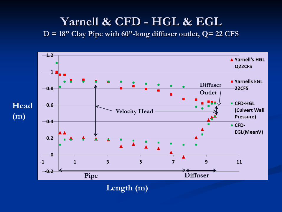
Yarnell & CFD - HGL & EGL D = 18” Clay Pipe with 60”-long diffuser outlet, Q= 22 CFS
Length (m)
Head (m)
Diffuser Pipe
Velocity Head
Diffuser Outlet

Outlet Loss Coefficient
Source: Source: Fundamentals of Fluid Mechanics, Munson, Young, p. 502 Okiishi, 1998 Outlet loss coefficient – Minimized at a flare angle of 12o
At small flare angles shear with the diffuser wall is the source of the loss At large angles separation and recirculation are associated with increased losses

Why the Difference in the Minimum Pressure at the Diffuser Inlet?
Interaction of water with culvert wall. Pipe Roughness
Clay Pipe n=0.0122 (roughness height 0.5mm to 1mm)
Pipe Wall Shear Stress – Rouse’s Research “Wetting agents” (hydrophilic)
Allow Culvert to fill when H/D > 0.9 Allow Culvert to stay full to the outlet of the pipe creating a
vacuum near the outlet of the pipe. Grease or Wax (hydrophobic)
Allow water surface to drop away from the top of the pipe near the outlet loosing the vacuum.

Summary By utilizing existing physical model data to
calibrate/verify the CFD model many questions can be answered.
CFD models of simple pipes are relatively easy to construct and the results are very close to physical models.
Properly designed diffusers function very predictably in both Physical and CFD models.
The unusual physics of diffusers lead to noticeable differences in the model outputs.

Questions
Yarnell’s Diffuser outlet

Hydraulic Design of Highway Culverts – Third Edition, Schall, James D., Thompson, Philip L., Zerges, Steve M., Kilgore, Roger T., and Morris Johnny L.; April 2012 U.S. Dept. of Transportation, Federal Highway Administration; Hydraulic Design Series No. 5; Publication No. FHWA-HIF-12-026
The Flow of Water Through Culverts; Yarnell, David L., Nagler, Floyd A., Woodward, Sherman M.; 1926; University of Iowa Studies in
Engineering
The Effects of Flared Outlets on the Discharge of Box Culverts; Venegas, Leon E.; 1950; Louisiana State University, MS Thesis, The School of Hydraulic Engineering
The Effect of Length on Performance Characteristics of Diffusers; Smith, Richard A.; 1951; Louisiana State University, MS Thesis, The School of Hydraulic Engineering
Conversion of Kinetic to Potential Energy in Flow Expansions; Kalinske, A. A.; 1946; pp.355 – Selected 390; Transactions, American Society of Civil Engineers, Paper No. 2273
Free Outlets and Self-Priming Action of Culverts; Li, Wen-Hsiung and Patterson, Calvin C.; 1956; pp. 1009-1 – 1009-22; Journal of the Hydraulics Division, Proceedings of the American Society of Civil Engineers
Design of Minimum Energy Culverts; McKay, G. R.; 1971; University of Queensland, Australia, Department of Civil Engineering Hydraulics of Minimum Energy Culverts Bridge Waterways; Apelt, C. J.; 1981; Conference on Hydraulics in Civil
Engineering, Sidney, Australia
Culvert Hydraulics, A Library Study; Division of Engineering Laboratories; 1962; Hydraulics Branch Report No. Hyd-489; United States Department of the Interior Bureau of Reclamation
The Hydraulic Design of Flume and Siphon Transitions; Hinds, Julian; 1927; pp.1423 – 1459; Transactions, American Society of Civil Engineers, Paper No. 1690
Improved Culvert Performance through Design and Research Studies; Bauer, William J.; 1959; Civil Engineering, pp. 53–55. Hydraulic Loss Coefficients for Culverts, Tullis, Blake P.; 2012, NCHRP, Transportation Research Board
References