utilization of residual helium to extend satellite...
TRANSCRIPT

Utilization of Residual Helium to Extend Satellite Lifetimesand Mitigate Space Debris
Mitchell L. R. Walker∗
Georgia Institute of Technology, Atlanta, Georgia 30332
Ryan P. Russell†
The University of Texas at Austin, Austin, Texas 78712-0235
and
Lake A. Singh‡
Georgia Institute of Technology, Atlanta, Georgia 30332
DOI: 10.2514/1.B34498
A new electric propulsion device concept takes advantage of residual helium gas that is trapped in the chemical
propellant feed system and currently unused at end of life. The helium ion thruster provides additional propellant
resources to extend satellite lifetimes and transfer geostationary orbit space assets to ultrasafe disposal orbits. The
predicted capability, if fully allotted to the disposal, allows for perigee heights above the geostationary altitude that
are one order of magnitude greater than existing international guidelines of�250 km. Furthermore, the proposed
helium ion thruster concept makes the classic propellant gauge uncertainty problem moot, as satellite operators
could use all of their conventional propellant for nominal station-keeping operations. The helium ion thruster
concept therefore mitigates future space debris arising from depleted assets in the geostationary orbit belt through
both aggressive orbit raising and depressurization of satellites at end of life. An analysis of the helium ion thruster
theoretical performance shows that the device could raise the altitude of an end-of-life 2500 kg, 5 kW spacecraft by
2200 km in two months using 2 kg of residual helium.
Nomenclature
a = semimajor axis, me = electron charge, Cg0 = gravitational acceleration at Earth’s surface, m=s2
H.O.T. = higher-order termsIsp = specific impulse, sI�sp = specific impulse of an alternative thruster, sm = propellant molecular mass, spacecraft mass, kgmHIT = dry mass of helium ion thruster, kgm0 = pre-disposal-maneuver mass, kgmp = propellant mass, kgPinput = power supplied to the thruster, WPionization = power required to ionize the propellant, WPother = power consumed by losses, WPthrust = jet power from the exhaust flow, Wr = orbit radius, mrb = burnout radius, mt = time, sVB = beam voltage, VVNC = neutralizer coupling voltage, Vv = velocity, m=s� = efficiency factor accounting for beam divergence
and double ion production
� = ratio of propellant and pre-disposal-maneuvermasses
�VH = Hohmann velocity increment, m=s" = ion production cost, eV� = thrust efficiency�u = propellant utilization efficiency� = ratio of Isp for the helium ion thruster and a nominal
thruster� = gravitational parameter of Earth, m3=s2
� = efficiency
I. Introduction
U NCERTAINTY in propellant reserve estimations, financialpressures, and lack of regulatory requirements have led to an
alarmingly low success rate of geostationary Earth orbit (GEO)satellites reaching proper disposal orbits at end of life (EOL). Spacedebris hazards to assets in the GEO belt continue to increase in partdue to this low success rate. The combination of the extraordinaryvalue of GEO satellites, the crowded nature of GEO slots, and recentstudies have highlighted that the space debris problem at GEO is ofgreat concern to the entire space community [1–3]. Nearly half of allcurrently operating spacecraft are in the GEO environment [2].Almost 20% of objects near GEO are abandoned assets drifting in alllongitudes of the protected GEO ring while many intrude daily intothe protected region [3]. A recent paper [2] argues that explosions inGEO are the greatest debris risk and suggests that the EOL guideline“does not improve the situation much, because even just a dozenexplosionswould be sufficient to double the average flux of debris. . .thus matching the effect of the existing background. . .a re-orbitingaltitude at least 2000 km above GEO should be used.”
Currently, the U.S. Space Object Catalog lists approximately15,000 trackable objects accounting for approximately 5800 tons ofon-orbit mass. The total debris population is thought to exceed20,000 objects larger than 10 cm [4]. The catalogue maintenanceproblem is already an international concern of extraordinary size andcomplexity, and its scope is somewhat unbounded with the potentialfor exponential growth. Figure 1 shows the growth of trackableobjects by category over the history of spaceflight. The evolution of
Received 7 November 2011; revision received 16 May 2012; accepted forpublication 18 May 2012. Copyright © 2012 by Mitchell Walker, Ryan P.Russell, and Lake Singh. Published by the American Institute of AeronauticsandAstronautics, Inc., with permission. Copies of this papermay bemade forpersonal or internal use, on condition that the copier pay the $10.00 per-copyfee to the Copyright Clearance Center, Inc., 222 Rosewood Drive, Danvers,MA 01923; include the code 0748-4658/12 and $10.00 in correspondencewith the CCC.
∗Associate Professor, Department of Aerospace Engineering, 270 FerstDrive NW. Associate Fellow AIAA.
†Assistant Professor, Department of Aerospace Engineering andEngineering Mechanics, 210 E. 24th St. Stop C0600, Austin, TX 78712-1221; [email protected]. Senior Member AIAA.
‡Graduate Student, Department ofAerospace Engineering, 270 Ferst DriveNW. Student Member AIAA.
JOURNAL OF PROPULSION AND POWER
Vol. 28, No. 6, November–December 2012
1406
Dow
nloa
ded
by G
eorg
ia T
ech
Lib
rary
on
Janu
ary
8, 2
013
| http
://ar
c.ai
aa.o
rg |
DO
I: 1
0.25
14/1
.605
63
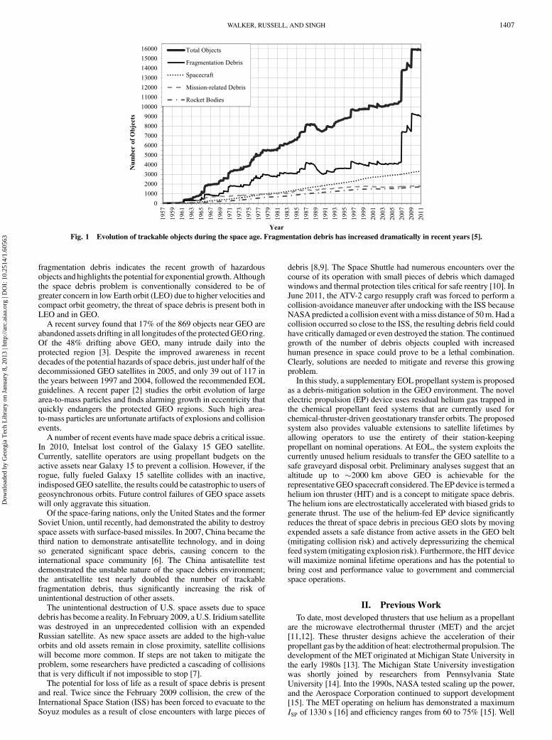
fragmentation debris indicates the recent growth of hazardousobjects and highlights the potential for exponential growth.Althoughthe space debris problem is conventionally considered to be ofgreater concern in low Earth orbit (LEO) due to higher velocities andcompact orbit geometry, the threat of space debris is present both inLEO and in GEO.
A recent survey found that 17% of the 869 objects near GEO areabandoned assets drifting in all longitudes of the protectedGEO ring.Of the 48% drifting above GEO, many intrude daily into theprotected region [3]. Despite the improved awareness in recentdecades of the potential hazards of space debris, just under half of thedecommissioned GEO satellites in 2005, and only 39 out of 117 inthe years between 1997 and 2004, followed the recommended EOLguidelines. A recent paper [2] studies the orbit evolution of largearea-to-mass particles and finds alarming growth in eccentricity thatquickly endangers the protected GEO regions. Such high area-to-mass particles are unfortunate artifacts of explosions and collisionevents.
A number of recent events have made space debris a critical issue.In 2010, Intelsat lost control of the Galaxy 15 GEO satellite.Currently, satellite operators are using propellant budgets on theactive assets near Galaxy 15 to prevent a collision. However, if therogue, fully fueled Galaxy 15 satellite collides with an inactive,indisposed GEO satellite, the results could be catastrophic to users ofgeosynchronous orbits. Future control failures of GEO space assetswill only aggravate this situation.
Of the space-faring nations, only the United States and the formerSoviet Union, until recently, had demonstrated the ability to destroyspace assets with surface-based missiles. In 2007, China became thethird nation to demonstrate antisatellite technology, and in doingso generated significant space debris, causing concern to theinternational space community [6]. The China antisatellite testdemonstrated the unstable nature of the space debris environment;the antisatellite test nearly doubled the number of trackablefragmentation debris, thus significantly increasing the risk ofunintentional destruction of other assets.
The unintentional destruction of U.S. space assets due to spacedebris has become a reality. In February 2009, aU.S. Iridium satellitewas destroyed in an unprecedented collision with an expendedRussian satellite. As new space assets are added to the high-valueorbits and old assets remain in close proximity, satellite collisionswill become more common. If steps are not taken to mitigate theproblem, some researchers have predicted a cascading of collisionsthat is very difficult if not impossible to stop [7].
The potential for loss of life as a result of space debris is presentand real. Twice since the February 2009 collision, the crew of theInternational Space Station (ISS) has been forced to evacuate to theSoyuz modules as a result of close encounters with large pieces of
debris [8,9]. The Space Shuttle had numerous encounters over thecourse of its operation with small pieces of debris which damagedwindows and thermal protection tiles critical for safe reentry [10]. InJune 2011, the ATV-2 cargo resupply craft was forced to perform acollision-avoidance maneuver after undocking with the ISS becauseNASApredicted a collision eventwith amiss distance of 50m.Had acollision occurred so close to the ISS, the resulting debris field couldhave critically damaged or even destroyed the station. The continuedgrowth of the number of debris objects coupled with increasedhuman presence in space could prove to be a lethal combination.Clearly, solutions are needed to mitigate and reverse this growingproblem.
In this study, a supplementary EOL propellant system is proposedas a debris-mitigation solution in the GEO environment. The novelelectric propulsion (EP) device uses residual helium gas trapped inthe chemical propellant feed systems that are currently used forchemical-thruster-driven geostationary transfer orbits. The proposedsystem also provides valuable extensions to satellite lifetimes byallowing operators to use the entirety of their station-keepingpropellant on nominal operations. At EOL, the system exploits thecurrently unused helium residuals to transfer the GEO satellite to asafe graveyard disposal orbit. Preliminary analyses suggest that analtitude up to �2000 km above GEO is achievable for therepresentativeGEO spacecraft considered. The EP device is termed ahelium ion thruster (HIT) and is a concept to mitigate space debris.The helium ions are electrostatically accelerated with biased grids togenerate thrust. The use of the helium-fed EP device significantlyreduces the threat of space debris in precious GEO slots by movingexpended assets a safe distance from active assets in the GEO belt(mitigating collision risk) and actively depressurizing the chemicalfeed system (mitigating explosion risk). Furthermore, theHIT devicewill maximize nominal lifetime operations and has the potential tobring cost and performance value to government and commercialspace operations.
II. Previous Work
To date, most developed thrusters that use helium as a propellantare the microwave electrothermal thruster (MET) and the arcjet[11,12]. These thruster designs achieve the acceleration of theirpropellant gas by the addition of heat: electrothermal propulsion. Thedevelopment of the METoriginated at Michigan State University inthe early 1980s [13]. The Michigan State University investigationwas shortly joined by researchers from Pennsylvania StateUniversity [14]. Into the 1990s, NASA tested scaling up the power,and the Aerospace Corporation continued to support development[15]. The MET operating on helium has demonstrated a maximumISP of 1330 s [16] and efficiency ranges from 60 to 75% [15]. Well
Fig. 1 Evolution of trackable objects during the space age. Fragmentation debris has increased dramatically in recent years [5].
WALKER, RUSSELL, AND SINGH 1407
Dow
nloa
ded
by G
eorg
ia T
ech
Lib
rary
on
Janu
ary
8, 2
013
| http
://ar
c.ai
aa.o
rg |
DO
I: 1
0.25
14/1
.605
63
before the envisioning of the MET, the idea of using helium in anarcjet was raised in the early 1960s. Although helium is a heavieratom than hydrogen, it is monatomic, and thus it is less prone tofrozen flow losses [17]. The helium arcjet design has achieved amaximum specific impulse ISP of 760 s and thrust of 112 mN at athrust efficiency of 50.2% [18].
To date, helium-fed EP devices have not been used on space assetsfor a number of reasons. First, the theoretical ionization energy ofhelium is 24.6 eV, which is the highest ionization energy of all theelements. It is more than two times greater than that of xenon(12.1 eV), the most common EP propellant. This means that asignificant amount of energy is wasted in the ionization process. Onpast low-power (<5 kW) satellites, the use of low-efficiency deviceswas not an option. Current and future generations of GEO satelliteswill operate at much higher powers (10–30 kW). Second, helium hasan extremely small ionization cross section. The small ionizationcross section results in a lower ionization rate of the propellant [19].Thus, even if sufficient power is available, standard electrostatic EPdevices cannot effectively use helium as a propellant.
The high ionization cost of helium leads to very low (<10%)electrostatic propulsion efficiency. Low efficiency requires highpower to generate appreciable thrust, which until the last decadewasnot available at EOL. As of 2011, in an EOL GEO satelliteapplication, engine efficiency is not a mission driver because thesatellite has on the order of 10 kWof electrical power available withminimal payload demands. The driver at EOL is ISP because itdetermines the maximum velocity increment that the vehicle canobtain. Thus, the low molecular weight and extremely high ISP of anHIT system are well-suited to GEO EOL applications.
III. Proposed Concept and Expected Performance
For a helium-fed EP device to deliver themost substantial velocityincrement to a GEO size communications satellite, a high ISP in therange of 5000 to 11,000 s is desired, which can only be achievedwithelectrostatic acceleration. The arcjet and MET concepts areinsufficient for this level of performance. The next section details theexpected performance of the proposed HIT device using helium.
A. Expected Performance
1. Helium as a Propellant
For a given electrostatic accelerationvoltage (typically between 20and 500 V), helium will have a higher ion velocity than xenon as aresult of their difference in mass. Consequently, a higher ISP isattainable with helium than with xenon at the same accelerationvoltage. In contrast, the efficiency of EP devices running helium isnot as favorable due to the high ionization cost of the propellant.However, for this novel EOL application, the system can tolerate lowthrust efficiency as long as the propellant utilization and ISP remain
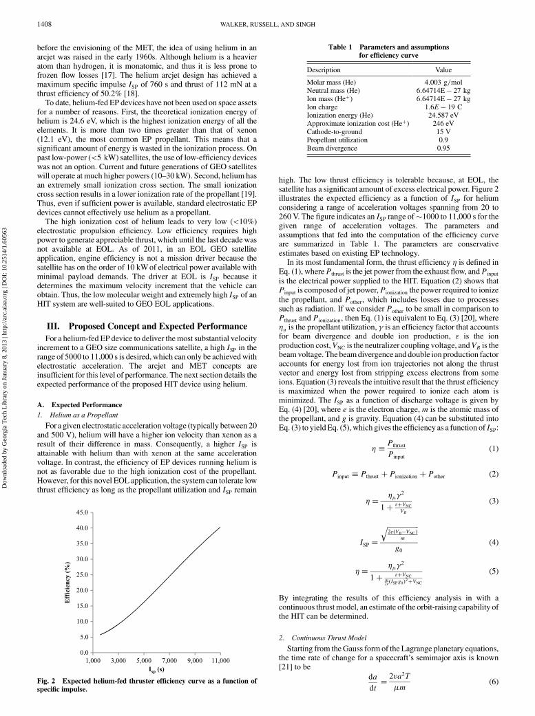
high. The low thrust efficiency is tolerable because, at EOL, thesatellite has a significant amount of excess electrical power. Figure 2illustrates the expected efficiency as a function of ISP for heliumconsidering a range of acceleration voltages spanning from 20 to260 V. The figure indicates an ISP range of�1000 to 11,000 s for thegiven range of acceleration voltages. The parameters andassumptions that fed into the computation of the efficiency curveare summarized in Table 1. The parameters are conservativeestimates based on existing EP technology.
In its most fundamental form, the thrust efficiency � is defined inEq. (1), wherePthrust is the jet power from the exhaust flow, andPinput
is the electrical power supplied to the HIT. Equation (2) shows thatPinput is composed of jet power,Pionization the power required to ionizethe propellant, and Pother, which includes losses due to processessuch as radiation. If we consider Pother to be small in comparison toPthrust and Pionization, then Eq. (1) is equivalent to Eq. (3) [20], where�u is the propellant utilization, � is an efficiency factor that accountsfor beam divergence and double ion production, " is the ionproduction cost,VNC is the neutralizer coupling voltage, andVB is thebeamvoltage. The beamdivergence and double ion production factoraccounts for energy lost from ion trajectories not along the thrustvector and energy lost from stripping excess electrons from someions. Equation (3) reveals the intuitive result that the thrust efficiencyis maximized when the power required to ionize each atom isminimized. The ISP as a function of discharge voltage is given byEq. (4) [20], where e is the electron charge,m is the atomic mass ofthe propellant, and g is gravity. Equation (4) can be substituted intoEq. (3) to yield Eq. (5), which gives the efficiency as a function of ISP:
� � Pthrust
Pinput
(1)
Pinput � Pthrust � Pionization � Pother (2)
�����
2
1� "�VNCVB
(3)
ISP �
�������������������2e�VB�VNC�
m
qg0
(4)
�����
2
1� "�VNCm2e�ISPg0�2�VNC
(5)
By integrating the results of this efficiency analysis in with acontinuous thrustmodel, an estimate of the orbit-raising capability ofthe HIT can be determined.
2. Continuous Thrust Model
Starting from theGauss form of the Lagrange planetary equations,the time rate of change for a spacecraft’s semimajor axis is known[21] to be
da
dt� 2va2T
�m(6)
Table 1 Parameters and assumptions
for efficiency curve
Description Value
Molar mass (He) 4:003 g=molNeutral mass (He) 6:64714E� 27 kgIon mass (He�) 6:64714E� 27 kgIon charge 1:6E � 19 CIonization energy (He) 24.587 eVApproximate ionization cost (He�) 246 eVCathode-to-ground 15 VPropellant utilization 0.9Beam divergence 0.95
Fig. 2 Expected helium-fed thruster efficiency curve as a function of
specific impulse.
1408 WALKER, RUSSELL, AND SINGH
Dow
nloa
ded
by G
eorg
ia T
ech
Lib
rary
on
Janu
ary
8, 2
013
| http
://ar
c.ai
aa.o
rg |
DO
I: 1
0.25
14/1
.605
63

where a is the semimajor axis,� is the gravitational parameter for theEarth, v is the velocity,m is the spacecraft mass, and T is the velocitydirection component of the perturbing thrust. For a GEO satellite,the eccentricity is approximately zero, leading to a� r andv� ��=r�1=2. We assume that small perturbations (i.e., due to a low-thrust EP system) are too small to accumulate an appreciableeccentricity. We further assume that the direction of thrust is pointedentirely along the spacecraft velocity vector, the optimal energyraising direction for the zero eccentricity case. This simple controllaw (of full thrust aligned in the velocity direction) is near-optimal forthe case of small eccentricity and leads to a simplified differentialequation for radius that can be solved in closed form. Equation (6)then reduces to
dr
dt� 2
T
m
�����r3
�
s(7)
Equation (8) gives thrust in terms of available power P, efficiency �,and specific impulse ISP:
T � 2�P=�g0ISP� (8)
Althoughmass is a linear function of time, given in Eqs. (9) and (10),assuming a maximum thrust level and its associated constant massflow rate,
_m��T=�g0ISP� � �2�P=�g0ISP�2 (9)
m�m0 � � _m�t (10)
The final differential equation governing radius is then
dr
dt� r3=2 4�Pg0ISP����
�p �g20I2SPm0 � 2�Pt� (11)
with a closed-form solution:
r�t� � �r0
g0ISP�����r0p
ln�1 � 2�Pt
m0g20I2SP
�� ����
�p 2
(12)
The burnout time required to burn mP units of propellant is
tB ��mP= _m�mPg20I
2SP=�2�P� (13)
Therefore, applying t� tB to Eq. (12), the burnout radius is
rB ��r0
g0ISP�����r0p
ln�1 � mP
m0
�� ����
�p 2
(14)
Note that the efficiency and power terms affect the burnout timebut are canceled in the burnout radius. Therefore, only the propellantmass fraction and the specific impulse affect the burnout radius fora given starting radius r0 � rGEO and gravitational parameter�� �Earth.
3. Orbit-Raising Capability
Using Eq. (14), Fig. 3a illustrates the expected burnout radiussensitivity to ISP and propellant mass assuming an EOL spacecraftmass of 2500 kg. Using Eq. (13), Fig. 3b shows the required flighttime to complete the maneuver assuming the efficiency curve fromFig. 2 and a nominal power of 5 kW. From the contours, we showrepresentative performance for three different design points in the(mP, ISP) space in Table 2.
Figure 3 gives a preliminary performance picture of the broaddesign space for the HIT engine. The main assumptions of m0 �2500 kg and P� 5 kW are chosen conservatively, noting that GEOsatellites have typical dry masses of 1500–2500 kg and power levelsof 5–15 kW [22]. The nominal mass of residual helium at EOL isestimated to be 2–4 kg. This mass is a conservative estimate based onpublicly available listings of the propellant tank volumes of GEOcommercial satellites built by Boeing, Lockheed Martin, and SpaceSystems Loral [23–26]. The fuel mix, density of the fuel andoxidizer, and propellant mass lead to an estimate for a representativetank volume. Assuming an ambient temperature of 555 K and tankinternal pressure of 17 atm, ideal gas law calculations reveal theestimate of the resulting helium pressurant stored in the propulsionsystem. The ambient temperature is intentionally selected to be highto account for a ‘worst case’ scenario; an ambient temperature of350 K gives a range of pressurant mass between 3 and 5 kg.Considering a helium mass of 2 kg and ISP of 10,000 s, the EOLmaneuver is capable of raising the orbit by�2200 km in�2 months.An Isp of 10,000 s is reasonable, given the results of the Nuclear–Electric Xenon Ion System and high-power electric propulsion ionthruster performance tests [27,28]. Therefore, we estimate theperformance of the HIT engine to provide almost an order ofmagnitude more capability than that necessary to meet the existinggraveyard orbit perigee height (GEO��250 km) requirements.This seemingly excessiveHIT capability barely satisfies the 2000 kmthreshold given in [2] that results from evaluating explosion debrisfields at GEO.
A high-fidelity low-thrust trajectory optimization is considered toverify the approximations made to produce Fig. 3. In this simulatedproblem, a GEO spacecraft is initiated with a circular orbit at42,164.17 km, initial mass of 2500 kg, 2 kg of helium propellant, a10,000 s Isp helium ion thruster, and 5 kWof power, translating to aneffective power of 1.84 kW (or 1.83504655 kW for reproducibility
Fig. 3 a)Orbit-raising capability andb)flight times forEOLmaneuver using continuous, tangent thrust; dash-dash line: operating range for heliumarc
jet (state of the art, see Sec. II); dash-dot line: expected range for HIT.
Table 2 Representative expected performance from the HIT
engine (taken from Fig. 3)
Designpoint
He mass,kg
ISP, s Burnout height aboveGEO, km
Burnout time,days
1 3 1,000 325 6.72 3 4,000 1320 433 3 8,000 2710 744 2 10,000 2238 61
WALKER, RUSSELL, AND SINGH 1409
Dow
nloa
ded
by G
eorg
ia T
ech
Lib
rary
on
Janu
ary
8, 2
013
| http
://ar
c.ai
aa.o
rg |
DO
I: 1
0.25
14/1
.605
63
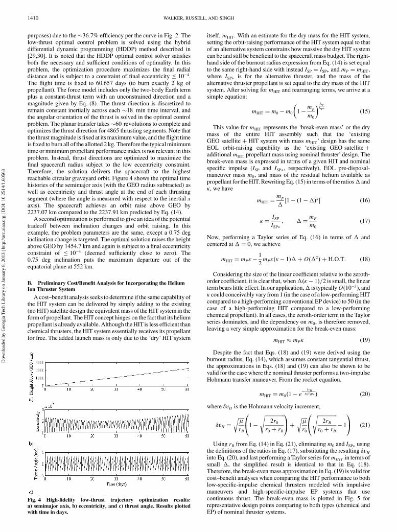
purposes) due to the �36:7% efficiency per the curve in Fig. 2. Thelow-thrust optimal control problem is solved using the hybriddifferential dynamic programming (HDDP) method described in[29,30]. It is noted that the HDDP optimal control solver satisfiesboth the necessary and sufficient conditions of optimality. In thisproblem, the optimization procedure maximizes the final radialdistance and is subject to a constraint of final eccentricity � 10�4.The flight time is fixed to 60.657 days (to burn exactly 2 kg ofpropellant). The force model includes only the two-body Earth termplus a constant-thrust term with an unconstrained direction and amagnitude given by Eq. (8). The thrust direction is discretized toremain constant inertially across each �18 min time interval, andthe angular orientation of the thrust is solved in the optimal controlproblem. The planar transfer takes�60 revolutions to complete andoptimizes the thrust direction for 4865 thrusting segments. Note thatthe thrustmagnitude isfixed at itsmaximumvalue, and theflight timeisfixed to burn all of the allotted 2 kg. Therefore the typicalminimumtime or minimum propellant performance index is not relevant in thisproblem. Instead, thrust directions are optimized to maximize thefinal spacecraft radius subject to the low eccentricity constraint.Therefore, the solution delivers the spacecraft to the highestreachable circular graveyard orbit. Figure 4 shows the optimal timehistories of the semimajor axis (with the GEO radius subtracted) aswell as eccentricity and thrust angle at the end of each thrustingsegment (where the angle is measured with respect to the inertial xaxis). The spacecraft achieves an orbit raise above GEO by2237.07 km compared to the 2237.91 km predicted by Eq. (14).
A second optimization is performed to give an idea of the potentialtradeoff between inclination changes and orbit raising. In thisexample, the problem parameters are the same, except a 0.75 deginclination change is targeted. The optimal solution raises the heightabove GEO by 1454.7 km and again is subject to a final eccentricityconstraint of � 10�4 (deemed sufficiently close to zero). The0.75 deg inclination puts the maximum departure out of theequatorial plane at 552 km.
B. Preliminary Cost/Benefit Analysis for Incorporating the Helium
Ion Thruster System
Acost–benefit analysis seeks to determine if the same capability ofthe HIT system can be delivered by simply adding to the existing(noHIT) satellite design the equivalent mass of the HIT system in theform of propellant. TheHIT concept hinges on the fact that its heliumpropellant is already available. Although theHIT is less efficient thanchemical thrusters, the HIT system essentially receives its propellantfor free. The added launch mass is only due to the ‘dry’ HIT system
itself, mHIT. With an estimate for the dry mass for the HIT system,setting the orbit-raising performance of the HIT system equal to thatof an alternative system constrains how massive the dry HIT systemcan be and still be beneficial to the spacecraft mass budget. The right-hand side of the burnout radius expression from Eq. (14) is set equalto the same right-hand side with instead ISP � ISP� and mP �mHIT,where ISP� is for the alternative thruster, and the mass of thealternative thruster propellant is set equal to the dry mass of the HITsystem. After solving for mHIT and rearranging terms, we arrive at asimple equation:
mHIT �m0 �m0
�1 �
mp
m0
� IspIsp�
(15)
This value for mHIT represents the ‘break-even mass’ or the drymass of the entire HIT assembly such that the ‘existingGEO satellite� HIT system with mass mHIT’ design has the sameEOL orbit-raising capability as the ‘existing GEO satellite�additionalmHIT propellant mass using nominal thruster’ design. Thebreak-even mass is expressed in terms of a given HIT and nominalspecific impulse (ISP and ISP�, respectively), EOL pre-disposal-maneuver mass m0, and mass of the residual helium available aspropellant for theHIT. Rewriting Eq. (15) in terms of the ratios� and�, we have
mHIT �mp
�1 � �1 ���� (16)
�� ISPISP�
; ��mP
m0
(17)
Now, performing a Taylor series of Eq. (16) in terms of � andcentered at �� 0, we achieve
mHIT �mP� �1
2mP��� � 1���O��2� � H:O:T: (18)
Considering the size of the linear coefficient relative to the zeroth-order coefficient, it is clear that, when��� � 1�=2 is small, the linearterm bears little effect. In our application,� is typicallyO�10�3�, and� could conceivably vary from 1 (in the case of a low-performingHITcompared to a high-performing conventional EP device) to 50 (in thecase of a high-performing HIT compared to a low-performingchemical propellant). In all cases, the zeroth-order term in the Taylorseries dominates, and the dependency on m0, is therefore removed,leaving a very simple approximation for the break-even mass:
mHIT �mP� (19)
Despite the fact that Eqs. (18) and (19) were derived using theburnout radius, Eq. (14), which assumes constant tangential thrust,the approximations in Eqs. (18) and (19) can also be shown to bevalid for the casewhere the nominal thruster performs a two-impulseHohmann transfer maneuver. From the rocket equation,
mHIT �m0�1 � e��vH
g0 ISP� � (20)
where �vH is the Hohmann velocity increment,
�vH �������
rB
r 0@1 �
����������������2r0
r0 � rB
s 1A� �����
�
r0
r 0@
����������������2rB
r0 � rB
s� 1
1A (21)
Using rB from Eq. (14) in Eq. (21), eliminatingm0 and ISP� usingthe definitions of the ratios in Eq. (17), substituting the resulting �vHinto Eq. (20), and last performing a Taylor series formHIT in terms ofsmall �, the simplified result is identical to that in Eq. (18).Therefore, the break-evenmass approximation in Eq. (19) is valid forcost–benefit analyses when comparing the HIT performance to bothlow-specific-impulse chemical thrusters modeled with impulsivemaneuvers and high-specific-impulse EP systems that usecontinuous thrust. The break-even mass is plotted in Fig. 5 forrepresentative design points comparing to both types (chemical andEP) of nominal thruster systems.
Fig. 4 High-fidelity low-thrust trajectory optimization results:
a) semimajor axis, b) eccentricity, and c) thrust angle. Results plotted
with time in days.
1410 WALKER, RUSSELL, AND SINGH
Dow
nloa
ded
by G
eorg
ia T
ech
Lib
rary
on
Janu
ary
8, 2
013
| http
://ar
c.ai
aa.o
rg |
DO
I: 1
0.25
14/1
.605
63
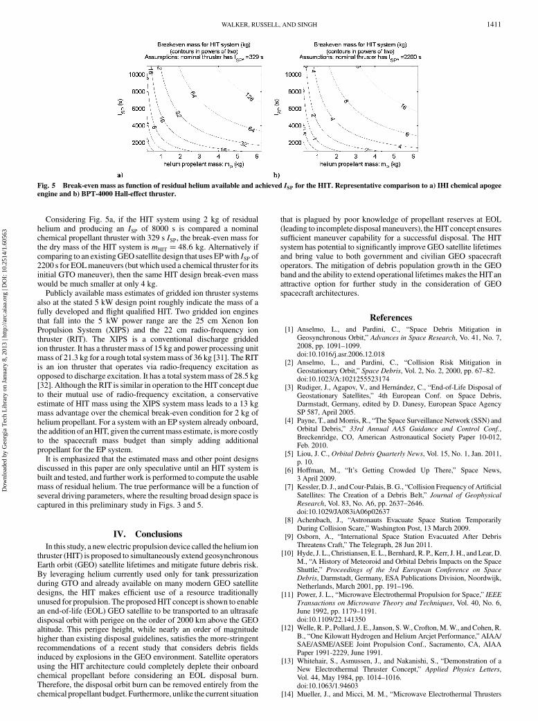
Considering Fig. 5a, if the HIT system using 2 kg of residualhelium and producing an ISP of 8000 s is compared a nominalchemical propellant thruster with 329 s ISP, the break-even mass forthe dry mass of the HIT system is mHIT � 48:6 kg. Alternatively ifcomparing to an existingGEOsatellite design that uses EPwith ISP of2200 s for EOLmaneuvers (but which used a chemical thruster for itsinitial GTO maneuver), then the same HIT design break-even masswould be much smaller at only 4 kg.
Publicly available mass estimates of gridded ion thruster systemsalso at the stated 5 kW design point roughly indicate the mass of afully developed and flight qualified HIT. Two gridded ion enginesthat fall into the 5 kW power range are the 25 cm Xenon IonPropulsion System (XIPS) and the 22 cm radio-frequency ionthruster (RIT). The XIPS is a conventional discharge griddedion thruster. It has a thruster mass of 15 kg and power processing unitmass of 21.3 kg for a rough total systemmass of 36 kg [31]. The RITis an ion thruster that operates via radio-frequency excitation asopposed to discharge excitation. It has a total systemmass of 28.5 kg[32]. Although the RIT is similar in operation to the HIT concept dueto their mutual use of radio-frequency excitation, a conservativeestimate of HIT mass using the XIPS system mass leads to a 13 kgmass advantage over the chemical break-even condition for 2 kg ofhelium propellant. For a system with an EP system already onboard,the addition of anHIT, given the currentmass estimate, ismore costlyto the spacecraft mass budget than simply adding additionalpropellant for the EP system.
It is emphasized that the estimated mass and other point designsdiscussed in this paper are only speculative until an HIT system isbuilt and tested, and further work is performed to compute the usablemass of residual helium. The true performance will be a function ofseveral driving parameters, where the resulting broad design space iscaptured in this preliminary study in Figs. 3 and 5.
IV. Conclusions
In this study, a newelectric propulsion device called the helium ionthruster (HIT) is proposed to simultaneously extend geosynchronousEarth orbit (GEO) satellite lifetimes and mitigate future debris risk.By leveraging helium currently used only for tank pressurizationduring GTO and already available on many modern GEO satellitedesigns, the HIT makes efficient use of a resource traditionallyunused for propulsion. The proposedHIT concept is shown to enablean end-of-life (EOL) GEO satellite to be transported to an ultrasafedisposal orbit with perigee on the order of 2000 km above the GEOaltitude. This perigee height, while nearly an order of magnitudehigher than existing disposal guidelines, satisfies the more-stringentrecommendations of a recent study that considers debris fieldsinduced by explosions in the GEO environment. Satellite operatorsusing the HIT architecture could completely deplete their onboardchemical propellant before considering an EOL disposal burn.Therefore, the disposal orbit burn can be removed entirely from thechemical propellant budget. Furthermore, unlike the current situation
that is plagued by poor knowledge of propellant reserves at EOL(leading to incomplete disposalmaneuvers), theHIT concept ensuressufficient maneuver capability for a successful disposal. The HITsystem has potential to significantly improve GEO satellite lifetimesand bring value to both government and civilian GEO spacecraftoperators. The mitigation of debris population growth in the GEOband and the ability to extend operational lifetimes makes the HITanattractive option for further study in the consideration of GEOspacecraft architectures.
References
[1] Anselmo, L., and Pardini, C., “Space Debris Mitigation inGeosynchronous Orbit,” Advances in Space Research, Vo. 41, No. 7,2008, pp. 1091–1099.doi:10.1016/j.asr.2006.12.018
[2] Anselmo, L., and Pardini, C., “Collision Risk Mitigation inGeostationary Orbit,” Space Debris, Vol. 2, No. 2, 2000, pp. 67–82.doi:10.1023/A:1021255523174
[3] Rudiger, J., Agapov, V., and Hernández, C., “End-of-Life Disposal ofGeostationary Satellites,” 4th European Conf. on Space Debris,Darmstadt, Germany, edited by D. Danesy, European Space AgencySP 587, April 2005.
[4] Payne, T., andMorris, R., “The Space Surveillance Network (SSN) andOrbital Debris,” 33rd Annual AAS Guidance and Control Conf.,Breckenridge, CO, American Astronautical Society Paper 10-012,Feb. 2010.
[5] Liou, J. C., Orbital Debris Quarterly News, Vol. 15, No. 1, Jan. 2011,p. 10.
[6] Hoffman, M., “It’s Getting Crowded Up There,” Space News,3 April 2009.
[7] Kessler, D. J., andCour-Palais, B. G., “Collision Frequency ofArtificialSatellites: The Creation of a Debris Belt,” Journal of Geophysical
Research, Vol. 83, No. A6, pp. 2637–2646.doi:10.1029/JA083iA06p02637
[8] Achenbach, J., “Astronauts Evacuate Space Station TemporarilyDuring Collision Scare,” Washington Post, 13 March 2009.
[9] Osborn, A., “International Space Station Evacuated After DebrisThreatens Craft,” The Telegraph, 28 Jun 2011.
[10] Hyde, J. L., Christiansen, E. L., Bernhard, R. P., Kerr, J. H., and Lear, D.M., “A History of Meteoroid and Orbital Debris Impacts on the SpaceShuttle,” Proceedings of the 3rd European Conference on Space
Debris, Darmstadt, Germany, ESA Publications Division, Noordwijk,Netherlands, March 2001, pp. 191–196.
[11] Power, J. L., “Microwave Electrothermal Propulsion for Space,” IEEETransactions on Microwave Theory and Techniques, Vol. 40, No. 6,June 1992, pp. 1179–1191.doi:10.1109/22.141350
[12] Welle, R. P., Pollard, J. E., Janson, S.W., Crofton,M.W., andCohen, R.B., “One Kilowatt Hydrogen and Helium Arcjet Performance,” AIAA/SAE/ASME/ASEE Joint Propulsion Conf., Sacramento, CA, AIAAPaper 1991-2229, June 1991.
[13] Whitehair, S., Asmussen, J., and Nakanishi, S., “Demonstration of aNew Electrothermal Thruster Concept,” Applied Physics Letters,Vol. 44, May 1984, pp. 1014–1016.doi:10.1063/1.94603
[14] Mueller, J., and Micci, M. M., “Microwave Electrothermal Thrusters
Fig. 5 Break-even mass as function of residual helium available and achieved ISP for the HIT. Representative comparison to a) IHI chemical apogee
engine and b) BPT-4000 Hall-effect thruster.
WALKER, RUSSELL, AND SINGH 1411
Dow
nloa
ded
by G
eorg
ia T
ech
Lib
rary
on
Janu
ary
8, 2
013
| http
://ar
c.ai
aa.o
rg |
DO
I: 1
0.25
14/1
.605
63
Using Waveguide Heated Plasmas,” 21st AIAA/DGLR/JSASSInternational Electric Propulsion Conf., Orlando, FL, AIAAPaper 1990-2562, July 1990.
[15] Diamant, K. D., “Microwave Electrothermal Thruster Performance,”Journal of Propulsion and Power, Vol. 23, No. 1, Jan.–Feb. 2007,pp. 27–34.doi:10.2514/1.19571
[16] Souliez, F. J., Chianese, S. G., Dizac, G. H., and Micci, M. M., “Low-Power Microwave Arcjet Testing: Plasma and Plume Diagnostic andPerformance Evaluation,” Micropropulsion for Small Spacecraft,edited by M. M. Micci and A. D. Ketsdever, Vol. 187, Progress inAstronautics and Aeronautics, AIAA, Reston, VA, 2000, pp. 199–214.
[17] Welle, R. P., “Space Propulsion Applications of HeliumArcjets,”DTICSMC-TR-00-13, 2000, pp. 1–13.
[18] Rybakov, A., Auweter-Kurtz, M., Kurtz, H., and Riehle, M.,“Investigations of the 1 kW Class Arcjet ARTUR-2 with Helium asPropellant,” 38thAIAA/ASME/SAE/ASEE Joint PropulsionConf. andExhibit, Indianapolis, IN, AIAA Paper 2002-3659, July 2002.
[19] Ahedo, E., Martinez-Cerezo, P., and Martinez-Sanchez, M., “One-Dimensional Model of the Plasma Flow in a Hall Thruster,” Physics ofPlasmas, Vol. 8, No. 6, 2001, pp. 3058–3068.doi:10.1063/1.1371519
[20] Jahn,R.G.,Physics of Electric Propulsion, Vol. 1,McGraw–Hill, 1968,pp. 142–195.
[21] Battin, R. H., An Introduction to the Mathematics and Methods of
Astrodynamics, AIAA, New York, 1987, p. 489.[22] Spence, B. R., Jones, P. A., Eskenazi, M. I., and Murphy, D. M., “The
SCARLET Solar Array for High Power GEO Satellites,” IEEE
Photovoltaic Specialists Conf., IEEE Publ., Piscataway, NJ, 1997,pp. 1027–1030.
[23] “AS 2100,” Encyclopedia Astronautica, http://www.astronautix.com/craft/as2100.htm [retrieved 23 September 2011].
[24] “FS-1300,” Encyclopedia Astronautica, http://www.astronautix.com/craft/fs1300.htm [retrieved 23 September 2011].
[25] “HS 702,” Encyclopedia Astronautica, http://www.astronautix.com/
craft/hs702.htm [retrieved 23 September 2011].[26] Arcioni, M., Daehler, E., Mueller, R. P., and van der Muelen, W.,
“S@tMax—A Space-Based System Enabling Mobile IP Applicationsin Vehicles,” Acta Astronautica, Vol. 64, pp. 1167–1179.doi:10.1016/j.actaastro.2009.01.028
[27] Goebel, D. M., Polk, J., and Sengupta, A., “Discharge ChamberPerformance of the NEXIS Ion Thruster,” 40th AIAA/ASME/SAE/ASEE Joint Propulsion Conference and Exhibit, Fort Lauderdale, FL,AIAA Paper 2004-3813, July 2004.
[28] Foster, J. E., Haag, T., Patterson, M., Williams, G. J. Jr., Sovey, J. S.,Carpenter, C., et al.,“The High Power Electric Propulsion (HiPEP) IonThruster,” 40th AIAA/ASME/SAE/ASEE Joint Propulsion Conference
and Exhibit, Fort Lauderdale, FL, AIAA Paper 2004-3812, July 2004.[29] Lantoine, G., and Russell, R. P., “A Hybrid Differential Dynamic
Programming Algorithm for Constrained Optimal Control Problems,Part 1: Theory,” Journal of Optimization Theory and Applications,Vol. 154, No. 2, 2012, pp. 382–417.doi: 10.1007/s10957-012-0039-0
[30] Lantoine, G., and Russell, R. P., “A Hybrid Differential DynamicProgramming Algorithm for Constrained Optimal Control Problems,Part 2: Applications,” Journal of Optimization Theory and
Applications, Vol. 154, No. 2, 2012, pp. 418–442.doi: 10.1007/s10957-012-0038-1
[31] Chien, K., Hart, S. L., Tighe, W. G., De Pano, M. K., Bond, T. A., andSpears, R., “L-3 Communications ETI Electric Propulsion Overview,”29th AIDAA/DGLR/JSASS International Electric Propulsion Confer-
ence, IEPC Paper 2005-315, Princeton, NJ, Oct. 2005.[32] Dachwald, B., Seboldt, W., Loeb, H. W., and Schartner, K. H., “Main
Belt Asteroid Sample ReturnMissionUsing Solar Electric Propulsion,”Acta Astronautica, Vol. 63, pp. 91–101.doi:10.1016/j.actaastro.2007.12.023
J. BlandinoAssociate Editor
1412 WALKER, RUSSELL, AND SINGH
Dow
nloa
ded
by G
eorg
ia T
ech
Lib
rary
on
Janu
ary
8, 2
013
| http
://ar
c.ai
aa.o
rg |
DO
I: 1
0.25
14/1
.605
63