utc - university transportation center
TRANSCRIPT
Show Me the Road to Hydrogen
Non-Destructive Evaluation (NDE)
by
K. Gupta, A. McClanahan, K. Erickson and R. Zoughi
at Missouri University of Science & Technology
A University Transportation Center Program
UTC R170

Disclaimer
The contents of this report reflect the views of the author(s), who are responsible for the facts and the
accuracy of information presented herein. This document is disseminated under the sponsorship of
the Department of Transportation, University Transportation Centers Program and the Center for
Infrastructure Engineering Studies UTC program at the University of Missouri - Rolla, in the interest
of information exchange. The U.S. Government and Center for Infrastructure Engineering Studies
assumes no liability for the contents or use thereof.
NUTC ###

Technical Report D
2. Government Accession No. Recipient's Catalog No. ocumentation Page
1. Report No.
UTC R170
3.
5. Report Date
February 2008
4. Title and Subtitle Show Me the Road to Hydrogen Non-Destructive Evaluation (NDE)
6. Performing Organization Code 7. Author/s
K. Gupta, A. McClanahan, K. Erickson and R. Zoughi
rganization Report No. 8. Performing O
00013054
10. Work Unit No. (TRAIS) 9. Performing Organization Name and Address
Center for Infrastructure Engineering Studies/UMissouri University of Science &223 Engineering R
TC program Technology
esearch Lab
o.
DTRS98-G-0021
Rolla, MO 65409
11. Contract or Grant N
13. Type of Report and Period Covered
Final
12. Sponsoring Organization Name and Address
U.S. Department of Transportation Research and Special Program400 7
s Administration
-0001 14. Sponsoring Agency Code th Street, SW
Washington, DC 20590
15. Supplementary Notes
16.
rom. ous
NDE methods for an effective synergistically integrat E of these different components.
Abstract Information is lacking about failure mechanisms associated with various hydrogen transportation systems, the types of typical failures, and critical locations where they may occur. Although one may consider these systems to be related to carbon-reinforced pressure vessels, their specific uses, material interactions with hydrogen, and unique in-service accumulated damages are expected to impose certain NDE restrictions and limitations that pressure vessels used in aerospace industry may not suffer fTherefore, in consultation with public safety authorities and experts, researchers must evaluate, select and bring in varisuitable ed approach to the ND
17. Key Words
Composite Storage Cylinders, Non-Destructive Testing and Evaluation onal Technical Information Service, Springfield, Virginia
18. Distribution Statement
No restrictions. This document is available to the public through the Nati22161.
19. Security Classification (of this report)
unclassified
ication (of this page) 21. No. Of s
47
22. Price 20. Security Classif
unclassified
Page
Form DOT F 1700.7 (8-72)
SHOW ME THE ROAD TO HYDROGEN
Task 5: Nondestructive Evaluation (NDE) K. Gupta, A. McClanahan, K. Erickson and R. Zoughi Electrical and Computer Engineering 141 Emerson Electric Co. Hall 1870 Miner Circle University of Missouri-Rolla Rolla, MO 65409

2
TABLE OF CONTENTS TABLE OF CONTENTS.................................................................................................... 2 LIST OF ILLUSTRATIONS.............................................................................................. 3 LIST OF TABLES.............................................................................................................. 4 1. INTRODUCTION .......................................................................................................... 5 2. HYDROGEN TANK MANUFACTURERS.................................................................. 6
2.1. Lincoln Composites ................................................................................................. 6 2.2. Quantum Technologies Inc. ..................................................................................... 6 2.3. Structural Composite Industries............................................................................... 6 2.4. Dynetek Industries Ltd............................................................................................. 6
3. HYDROGEN FILLING STATIONS ............................................................................. 7 3.1. Storage Tank ............................................................................................................ 8 3.2. High Pressure Storage Tubes ................................................................................... 8 3.3. Hydrogen Dispenser................................................................................................. 8 3.4. The Fueling Process................................................................................................. 9 3.5. Safety Standards and Procedures ............................................................................. 9
4. NONDESTRUCTIVE EVALUATION FOR CONDITION MONITORING OF HYDROGEN POWERED VEHICLES ........................................................................... 10
4.1. Modes of Onboard Hydrogen Storage ................................................................... 10 4.1.1. Compressed Gas.............................................................................................. 10 4.1.2 Liquid Hydrogen.............................................................................................. 12 4.1.3 Hydrides........................................................................................................... 13 4.1.4 Carbon Nanostructures..................................................................................... 14 4.1.5 Innovative Concepts......................................................................................... 15 4.1.6 Tank Location in Vehicle................................................................................. 15
4.2. Destructive Testing of Hydrogen Storage Tanks................................................... 19 4.3. Nondestructive Testing of Hydrogen Storage Tanks............................................. 22 4.4. Design for Inspectability........................................................................................ 30
5. STANDARDS AND INSPECTION CODES .............................................................. 31 6. REQUIREMENTS FOR THE HYDROGEN INFRASTRUCTURE .......................... 33 7. DEMONSTRATIONS/PROOF OF CONCEPT........................................................... 34
7.1. Laser Ultrasonic Camera........................................................................................ 34 7.2. Thermographic Camera ......................................................................................... 34
8. VISIT TO LINCOLN COMPOSITES, INC. ………………………………………... 35 9. SUMMARY.................................................................................................................. 38 10. ACKNOWLEDGEMENT …………………………………………………………. 39 11. BIBLIOGRAPHY …………………………………………………………………. 40 Appendix A....................................................................................................................... 43 Appendix B ....................................................................................................................... 46

3
LIST OF ILLUSTRATIONS Figure 1. Hydrogen filling station in Washington D.C. [6]. ............................................... 7 Figure 2. Hydrogen fuel dispenser at a filling station [8]. .................................................. 9 Figure 3. Cutaway view of a type IV cylinder [11]. ......................................................... 11 Figure 4. Stationary gaseous hydrogen storage [12]......................................................... 12 Figure 5. Liquid hydrogen tank [13]................................................................................. 13 Figure 6. Metal hydride [15]. ............................................................................................ 14 Figure 7. Hydrogen (red) bonded to carbon nanotube (light blue) using titanium (dark
blue) [17]................................................................................................................... 14 Figure 8. 4x4x4 macrolattice [19]..................................................................................... 15 Figure 9. Potential tank locations [20]. ............................................................................. 16 Figure 10. Hydrogen tank roof rack mount [21]............................................................... 17 Figure 11. GM Auto-nomy base [22]. .............................................................................. 18 Figure 12. Pillow shaped pressure tank [22]..................................................................... 18 Figure 13. Cylinder subjected to gunfire test with no observable fragmentation [24]. .... 21 Figure 14. Cylinder subjected to bonfire test [25]. ........................................................... 22 Figure 15. Composite over wrapped tank after hydrostatic burst test [26]....................... 22 Figure 16. Inspection bay for Ciatro busses in Madrid [12]. ............................................ 23 Figure 17. (a) Ultrasound testing of a graphite-epoxy tank using a receiver and transmitter
probe, (b) a Lockheed Martin LaserUTTM laser ultrasound unit testing a complex composite duct, (c) visual light image of composite cylinder showing no apparent damage (d) thermographic image of the cylinder in part (c) clearly reveals subsurface damage [30]. ........................................................................................... 28
Figure 18. Handheld thermographc camera [30]. ............................................................. 35
4
LIST OF TABLES Table 1. DOE goals for hydrogen storage [9]................................................................... 10 Table 2. Destructive tests performed on composite over wrapped hydrogen storage
cylinders [24]. ........................................................................................................... 19 Table 3. Nondestructive testing methods for composite over wrapped hydrogen pressure
vessels [9, 27-33]. ..................................................................................................... 24 Table 4. Health monitoring of composite hydrogen tanks using embedded sensors [33].29 Table 5. Inspection codes and standards for hydrogen infrastructure [34]....................... 31
5
1. INTRODUCTION
This report summarizes the literature review carried out by the authors from June to
December, 2007. The report summarizes various issues associated with manufacturing,
transporting, re-fueling and nondestructive testing of hydrogen storage tanks. Hydrogen
storage, and specifically compressed gas tanks, has been identified as an area where
nondestructive testing will be particularly useful and is thus covered in much greater
detail.
The rest of this report is structured as follows. Chapter 2 identifies the different hydrogen
tank manufactures and Chapter 3 provides a brief description of the components of a
typical hydrogen filling station along with some of the standards and codes that are
followed to ensure safe operation. Chapter 4 discusses the different modes of hydrogen
fuel storage on board vehicles. Destructive as well as nondestructive testing methods are
also discussed. Chapter 5 provides a summary of the existing standards and codes for the
inspection of hydrogen storage tanks and other components of the hydrogen
infrastructure. Some of the deficiencies of the existing codes and standards for the
hydrogen infrastructure have been summarized in Chapter 6 and a number of components
of the hydrogen infrastructure which lack formalized codes and standards are identified.
Effective maintenance of the hydrogen infrastructure requires the development of
innovative products which will reduce inspection time and reduce the complexity
involved in the inspection procedure. Two such state-of-the-art products are discussed in
Chapter 7. Chapter 8 summarizes the findings of this literature survey study.

6
2. HYDROGEN TANK MANUFACTURERS Four of the leading manufacturers of hydrogen storage tanks are described in this section.
2.1. Lincoln Composites Lincoln Composites produces Tuffshell type IV compressed gas storage tanks. Their
tanks are used for automobiles, busses, and stationary storage. They range in pressure
from 3,000 psi to 10,000 psi [1].
2.2. Quantum Technologies Inc. Quantum Technologies (QTWW) produces TriShield type IV compressed gas cylinders
for hydrogen storage as well as fuel metering, electronic controls and fuel system
integration. It has developed and demonstrated all-composite hydrogen storage tanks that
store hydrogen at 10,000 psi (700 Bar) [2]. They produce automobile storage tanks,
mobile fueling units, and other fueling products. Their tanks are used on Toyota cars.
Quantum is examining using integrated sensors in their tanks [3].
2.3. Structural Composite Industries Structural Composite Industries produces type III compressed gas cylinders. In the 1970s,
SCI helped the United States Department of Transportation develop the first safety
standards for composite fuel tanks, and SCI manufactured the first DOT approved
composite fuel tank. SCI also developed the first composite fuel tank certified under
European Standard ECE R110 [4].
2.4. Dynetek Industries Ltd. Dynetek produces DyneCell type III compressed gas cylinders for storage of natural gas
and hydrogen. Their tanks are used for automobiles, busses, mobile fueling stations, and
stationary storage. They range in pressure from 3,000 psi to 10,000 psi. An integral part
of Dynetek's expertise is its in-house testing facility used to validate and certify standard
and/or custom designs effectively [5]. Dynetek has cylinders in use in the Citaro busses
used by the Clean Urban Tranport for Europe (CUTE) project, the Ford Focus Fuel Cell
vehicle, the Volkswagen type Bora, Nissan Xterra, 2000 Mercedes Benz Necar, Ford
Focus FCV, Toyota FCHV and the Ford Hydrogen ICE vehicle.
7
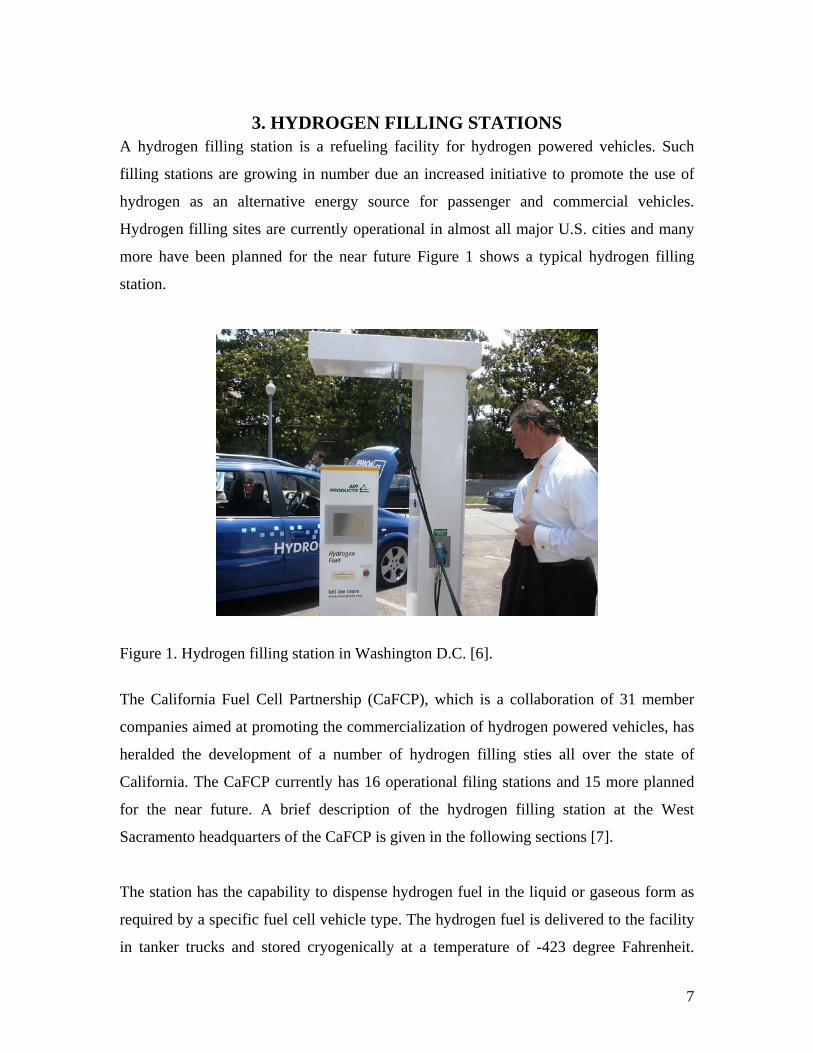
3. HYDROGEN FILLING STATIONS A hydrogen filling station is a refueling facility for hydrogen powered vehicles. Such
filling stations are growing in number due an increased initiative to promote the use of
hydrogen as an alternative energy source for passenger and commercial vehicles.
Hydrogen filling sites are currently operational in almost all major U.S. cities and many
more have been planned for the near future Figure 1 shows a typical hydrogen filling
station.
Figure 1. Hydrogen filling station in Washington D.C. [6].
The California Fuel Cell Partnership (CaFCP), which is a collaboration of 31 member
companies aimed at promoting the commercialization of hydrogen powered vehicles, has
heralded the development of a number of hydrogen filling sties all over the state of
California. The CaFCP currently has 16 operational filing stations and 15 more planned
for the near future. A brief description of the hydrogen filling station at the West
Sacramento headquarters of the CaFCP is given in the following sections [7].
The station has the capability to dispense hydrogen fuel in the liquid or gaseous form as
required by a specific fuel cell vehicle type. The hydrogen fuel is delivered to the facility
in tanker trucks and stored cryogenically at a temperature of -423 degree Fahrenheit.

8
Similar storage methods have been used in several industrial applications in the past but
this is one of the first instances of such usage for hydrogen storage at a commercially
operating filling station. The filling station has the flowing major components:
• One 4,500 gallon liquid hydrogen storage tank
• A vaporizer for warming the liquid hydrogen to its gaseous form
• A compressor to raise the gas pressure to 6250 psig (pounds per square inch
gauge)
• Three tubes for storing gaseous hydrogen
• Two gaseous dispensers at 3600 psig and 5000 psig and a liquid hydrogen
dispenser
3.1. Storage Tank The storage tank is an ASME coded double walled pressure vessel. The inner steel wall is
½ inch in thickness and built to withstand a pressure of 150 psi and tested to 225 psi. The
actual operating pressure of the tank is in the range of 50 psi. As a safety measure the
tank has a number of redundant pressure valves which are designed to open in the event
of over pressure and release the hydrogen through a 25 foot high vent stack.
3.2. High Pressure Storage Tubes After compression hydrogen gas is stored in three steel storage tubes at 6250 psig. Like
the storage tank the tubes are also equipped with safety valves to release the gas in the
unlikely event of overpressure.
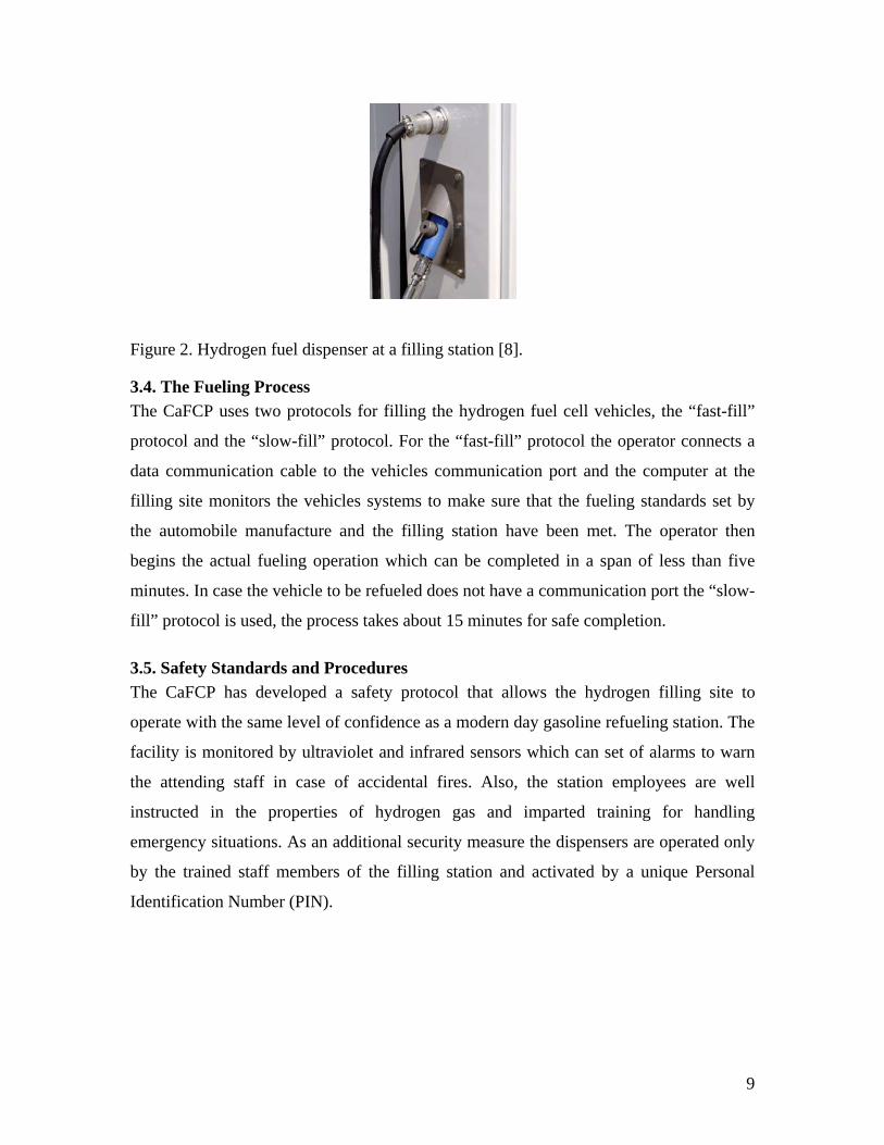
3.3. Hydrogen Dispenser The fuel station has one liquid and two gaseous dispensers. The liquid dispenser siphons
off liquid hydrogen directly from the storage tank and is vacuum jacketed in order to
ensure that the operator is protected by an insulating barrier and liquid hydrogen fuel is
delivered to the vehicle’s storage tank at the correct temperature. The fuelling interface
can be used with all of the three dispensers mentioned above and all hydrogen vehicles. It
has been designed collaboratively by a number of major automobile companies
participating in the CaFCPs hydrogen vehicle development program. Figure 2 shows a
hydrogen fuel dispenser at an operational refueling station.
9
Figure 2. Hydrogen fuel dispenser at a filling station [8].
3.4. The Fueling Process The CaFCP uses two protocols for filling the hydrogen fuel cell vehicles, the “fast-fill”
protocol and the “slow-fill” protocol. For the “fast-fill” protocol the operator connects a
data communication cable to the vehicles communication port and the computer at the
filling site monitors the vehicles systems to make sure that the fueling standards set by
the automobile manufacture and the filling station have been met. The operator then
begins the actual fueling operation which can be completed in a span of less than five
minutes. In case the vehicle to be refueled does not have a communication port the “slow-
fill” protocol is used, the process takes about 15 minutes for safe completion.
3.5. Safety Standards and Procedures The CaFCP has developed a safety protocol that allows the hydrogen filling site to
operate with the same level of confidence as a modern day gasoline refueling station. The
facility is monitored by ultraviolet and infrared sensors which can set of alarms to warn
the attending staff in case of accidental fires. Also, the station employees are well
instructed in the properties of hydrogen gas and imparted training for handling
emergency situations. As an additional security measure the dispensers are operated only
by the trained staff members of the filling station and activated by a unique Personal
Identification Number (PIN).
10
4. NONDESTRUCTIVE EVALUATION FOR CONDITION MONITORING OF HYDROGEN POWERED VEHICLES
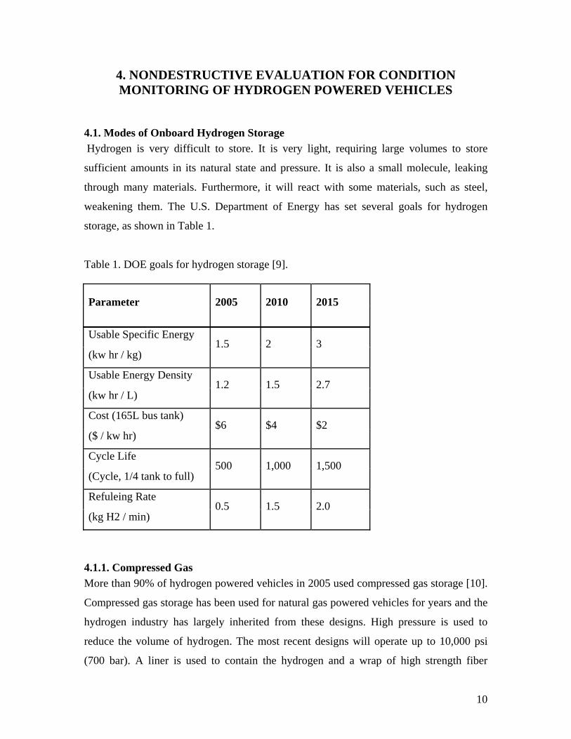
4.1. Modes of Onboard Hydrogen Storage Hydrogen is very difficult to store. It is very light, requiring large volumes to store
sufficient amounts in its natural state and pressure. It is also a small molecule, leaking
through many materials. Furthermore, it will react with some materials, such as steel,
weakening them. The U.S. Department of Energy has set several goals for hydrogen
storage, as shown in Table 1.
Table 1. DOE goals for hydrogen storage [9].
Parameter 2005 2010 2015
Usable Specific Energy
(kw hr / kg) 1.5 2 3
Usable Energy Density
(kw hr / L) 1.2 1.5 2.7
Cost (165L bus tank)
($ / kw hr) $6 $4 $2
Cycle Life
(Cycle, 1/4 tank to full) 500 1,000 1,500
Refuleing Rate
(kg H2 / min) 0.5 1.5 2.0
4.1.1. Compressed Gas More than 90% of hydrogen powered vehicles in 2005 used compressed gas storage [10].
Compressed gas storage has been used for natural gas powered vehicles for years and the
hydrogen industry has largely inherited from these designs. High pressure is used to
reduce the volume of hydrogen. The most recent designs will operate up to 10,000 psi
(700 bar). A liner is used to contain the hydrogen and a wrap of high strength fiber

11
provides the strength to withstand the pressure. Disadvantages include large volume and
safety concerns related to the high pressures. Compressing the hydrogen to 10,000 psi
requires about 12% of the energy contained in that hydrogen. Four types of tanks have
been developed for the compressed gas market; of these, type III and type IV tanks have
been used for hydrogen storage.
4.1.1.1 Type III Tanks. A metal liner contains the gas and a complete fiber wrap
provides most of the structural support against the pressure. Generally, in hydrogen
applications, aluminum is used for the liner and carbon or a carbon/fiberglass hybrid for
the fiber. Both loop and transverse wraps are used to provide strength in all directions.
4.1.1.2 Type IV Tanks. Type IV tanks are similar to the type III tanks except that a non-
metal (generally plastic) liner is used. Plastic liners have increased fatigue resistance but
provide less strength. They are also lighter then type III cylinders.
The Lincoln Composites Tuffshell tank is one example of a modern design for a type IV
tank. A cutaway view of this tank is shown in figure 3. This tank has a High Density
PolyEthylene (Plastic) liner wrapped with a carbon/glass hybrid fiber. This tank also
features energy absorbing pads on the corners and a fiberglass outer layer to provide
additional protection from impact damage. [11]
Figure 3. Cutaway view of a type IV cylinder [11].
12
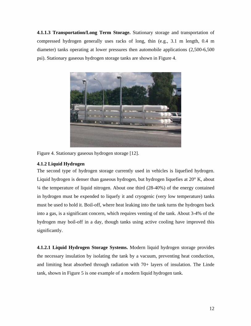
4.1.1.3 Transportation/Long Term Storage. Stationary storage and transportation of
compressed hydrogen generally uses racks of long, thin (e.g., 3.1 m length, 0.4 m
diameter) tanks operating at lower pressures then automobile applications (2,500-6,500
psi). Stationary gaseous hydrogen storage tanks are shown in Figure 4.
Figure 4. Stationary gaseous hydrogen storage [12].
4.1.2 Liquid Hydrogen The second type of hydrogen storage currently used in vehicles is liquefied hydrogen.
Liquid hydrogen is denser than gaseous hydrogen, but hydrogen liquefies at 20° K, about
¼ the temperature of liquid nitrogen. About one third (28-40%) of the energy contained
in hydrogen must be expended to liquefy it and cryogenic (very low temperature) tanks
must be used to hold it. Boil-off, where heat leaking into the tank turns the hydrogen back
into a gas, is a significant concern, which requires venting of the tank. About 3-4% of the
hydrogen may boil-off in a day, though tanks using active cooling have improved this
significantly.
4.1.2.1 Liquid Hydrogen Storage Systems. Modern liquid hydrogen storage provides
the necessary insulation by isolating the tank by a vacuum, preventing heat conduction,
and limiting heat absorbed through radiation with 70+ layers of insulation. The Linde
tank, shown in Figure 5 is one example of a modern liquid hydrogen tank.

13
Figure 5. Liquid hydrogen tank [13].
4.1.2.2 Insulated Cryogenic Pressure Vessels. Lawrence Livermore National
Laboratory is developing a tank taking advantage of both compressed and cryogenic
storage. This is achieved by nesting a pressure vessel inside a cryogenic vessel. This tank
can be operated as a pressure vessel, operated at low temperatures (~70° K) where the
fiber in the pressure vessel has significantly higher strength, or as a cryogenic vessel
storing liquid hydrogen. This would also allow the user to use compressed hydrogen for
locale trips where car range is of less concern and the higher energy cost liquid hydrogen
for longer trips. This system can also retain liquid hydrogen boil-off as compressed gas
[14].
4.1.3 Hydrides Hydrides chemically bond with hydrogen in a reversible process. The hydrogen can then
be stored compactly and recovered as needed.
4.1.3.1 Metal Hydrides. Metal hydrides are metals that chemically combine with
hydrogen, holding it in a small volume. The application of heat reverses the reaction and
frees the hydrogen, and heat is generally available as a byproduct of the fuel cell. A
typical application has powdered hydride metal and rods used to distribute heat contained
in a metal box. Because the reaction is self limiting this is also a safe way to store
hydrogen. Disadvantages include relatively large weight and the high cost.

14
Figure 6. Metal hydride [15].
4.1.3.2 Chemical Hydrides. Chemical hydride slurry has been developed that is 15.3%
hydrogen by weight. This slurry can be stored at room temperature and releases the
hydrogen when combined with water. This slurry is stable for weeks, will not ignite, and
is not contaminated by air. However, the reaction produces a hydroxide byproduct that
must be returned to an industrial location to be recharged with hydrogen, which would
require a much more extensive infrastructure [16].
4.1.4 Carbon Nanostructures Carbon nanotubes bond with hydrogen increasing the amount of hydrogen that can be
stored in a compressed gas tank. The best results have been obtained when metal atoms
are bonded to the nanotube and then also bond with the hydrogen [17]. Hydrogen storage
of 7% by weight has been achieved [15]. Other forms of carbon, such as activated carbon
and nanohorns, have also show promise for storing hydrogen [18].
Figure 7. Hydrogen (red) bonded to carbon nanotube (light blue) using titanium (dark blue) [17].

15
4.1.5 Innovative Concepts New and innovative solutions are constantly being proposed to improve hydrogen storage
and meet the DOE goals. A few of these are included.
4.1.5.1 Zeolites. Zeolites are microporous inorganic compounds. Hydrogen is captured in
micro pores to reduce volume. Thus far 0.7% hydrogen by weight has been achieved
[15].
4.1.5.2 Replicants. Replicants are an alternative method of providing structural support
to compressed gas tanks by repeatable small structures. One methods of this is
macrolattices, passing support columns through the storage chamber to allow localized
pressure support. A 4x4x4 strut cell has been built and it is expected that 20x20x20 will
be necessary for use in vehicles. Another method uses microscopic structures within the
tank to withstand high pressures [19].
Figure 8. 4x4x4 macrolattice [19].
4.1.6 Tank Location in Vehicle Tank location in vehicles is of particular concern because of the high volume required for
current systems. Figure 9 shows nine possible tank locations in a car, for this discussion
the first four have been grouped as floorboard storage, two have been grouped as trunk
storage, and the roof storage is included. The tank placements in front of the instrument
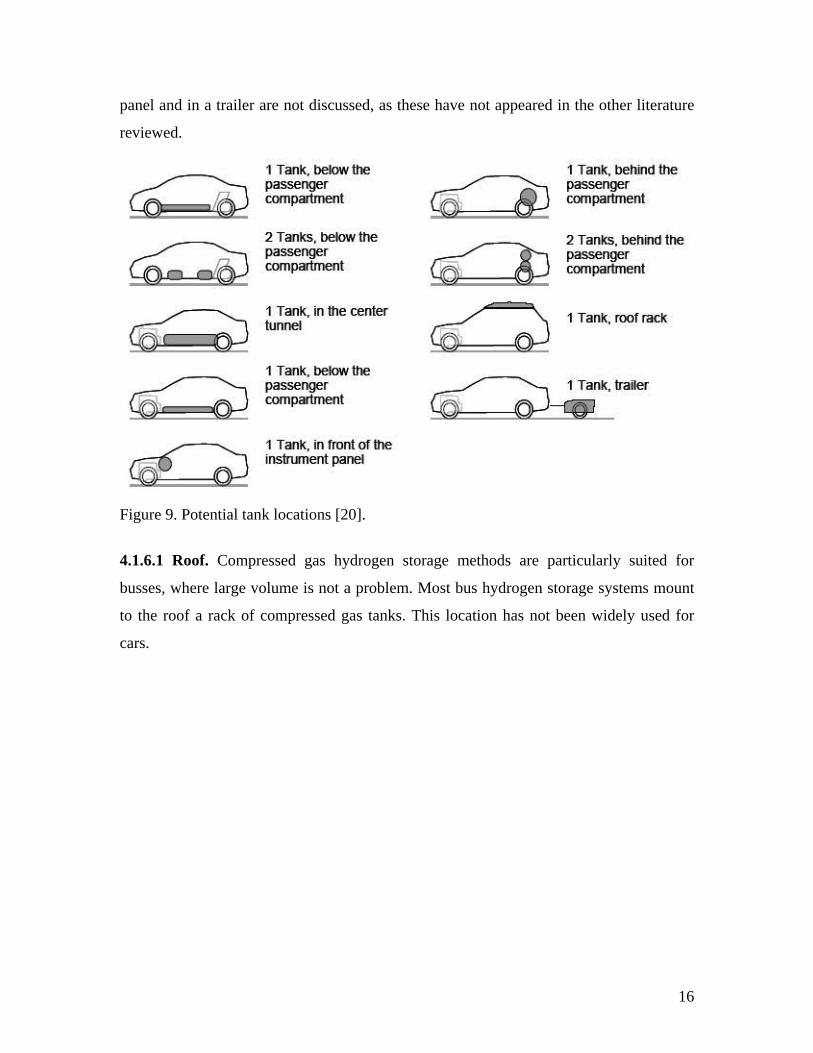
16
panel and in a trailer are not discussed, as these have not appeared in the other literature
reviewed.
Figure 9. Potential tank locations [20].
4.1.6.1 Roof. Compressed gas hydrogen storage methods are particularly suited for
busses, where large volume is not a problem. Most bus hydrogen storage systems mount
to the roof a rack of compressed gas tanks. This location has not been widely used for
cars.

17
Figure 10. Hydrogen tank roof rack mount [21].
4.1.6.2 Trunk. A car trunk or truck bed is large empty space that can be used to hold the
storage tank. This allows greater use of existing designs, but reduces the space available
for use as a trunk.
4.1.6.3 Floorboard. Several new hydrogen vehicle designs place the tanks underneath
the car floorboard. This is a fairly large area that can be devoted to hydrogen storage with
limited interference with passenger areas. This is particularly attractive when using a by-
wire system, such as the Auto-nomy by GM, which does not have a driveshaft.

18
Figure 11. GM Auto-nomy base [22].
4.1.6.4 Conformal Tanks. Research has begun on conformal tanks, both alternative
shapes for compressed gas tanks and shaped liquid hydrogen tanks. Pillow shaped
pressure vessels have achieved a burst pressure of 1,600 psi, about 7% of that achieved
by cylindrical tanks [22-23]
Figure 12. Pillow shaped pressure tank [22].

19
4.2. Destructive Testing of Hydrogen Storage Tanks A number of different tests are performed by tank manufacturers before the tanks are
installed in the vehicles to ensure compliance with standards set by the DOT (Department
of Transportation), SAE (Society of Automotive Engineers) and ISO (International
Standards Organization). Studies have been conducted to ascertain if additional tests are
required for ensuring that catastrophic failure does not occur under extreme operating
conditions arising out of accidents such as collisions, fires etc. Table 2 lists some of the
relevant additional tests [24]. The table is divided into three columns, the first column
lists the type of test, the second column lists the specific activities performed during the
test and the third column lists the criterion for successful completion of the test.
Table 2. Destructive tests performed on composite over wrapped hydrogen storage cylinders [24].
Type of Test Test Description Criteria for Success
Cycling, ambient temperature
10,000 cycles from less than 10% of service pressure to full service pressure, maximum 10 cycles/min
Cylinder must withstand the test with no visual indication of damage
Cycling, Environmental • 5000 cycles from 0 to service pressure with tank at 60 degree Celsius with air at ambient temperature and 95% humidity
• 5000 cycles from 0 to service pressure with tank at -51.1 degree Celsius with air at ambient temperature
• 30 cycles from 0 to service pressure at ambient conditions
• maximum 10 cycles/min
• Burst test the cycled tank
Cylinder must withstand the cycling pressurization test with no visual indication of damage
20
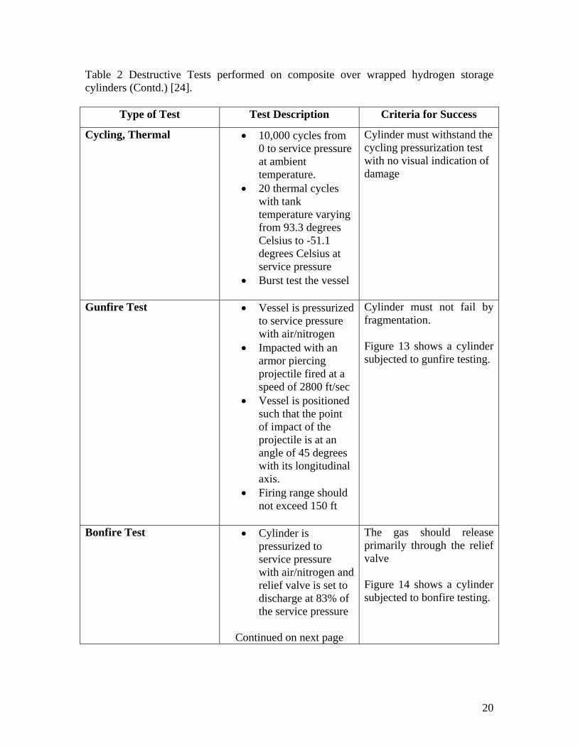
Table 2 Destructive Tests performed on composite over wrapped hydrogen storage cylinders (Contd.) [24].
Type of Test Test Description Criteria for Success
Cycling, Thermal • 10,000 cycles from 0 to service pressure at ambient temperature.
• 20 thermal cycles with tank temperature varying from 93.3 degrees Celsius to -51.1 degrees Celsius at service pressure
• Burst test the vessel
Cylinder must withstand the cycling pressurization test with no visual indication of damage
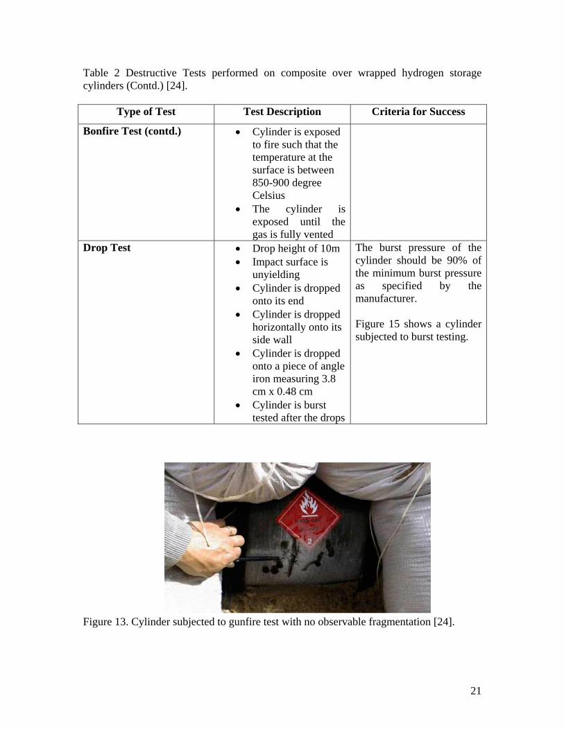
Gunfire Test
• Vessel is pressurized to service pressure with air/nitrogen
• Impacted with an armor piercing projectile fired at a speed of 2800 ft/sec
• Vessel is positioned such that the point of impact of the projectile is at an angle of 45 degrees with its longitudinal axis.
• Firing range should not exceed 150 ft
Cylinder must not fail by fragmentation. Figure 13 shows a cylinder subjected to gunfire testing.
Bonfire Test
• Cylinder is pressurized to service pressure with air/nitrogen and relief valve is set to discharge at 83% of the service pressure
Continued on next page
The gas should release primarily through the relief valve Figure 14 shows a cylinder subjected to bonfire testing.
21
Table 2 Destructive Tests performed on composite over wrapped hydrogen storage cylinders (Contd.) [24].
Type of Test Test Description Criteria for Success
Bonfire Test (contd.) • Cylinder is exposed to fire such that the temperature at the surface is between 850-900 degree Celsius
• The cylinder is exposed until the gas is fully vented
Drop Test • Drop height of 10m • Impact surface is
unyielding • Cylinder is dropped
onto its end • Cylinder is dropped
horizontally onto its side wall
• Cylinder is dropped onto a piece of angle iron measuring 3.8 cm x 0.48 cm
• Cylinder is burst tested after the drops
The burst pressure of the cylinder should be 90% of the minimum burst pressure as specified by the manufacturer. Figure 15 shows a cylinder subjected to burst testing.
Figure 13. Cylinder subjected to gunfire test with no observable fragmentation [24].

22
Figure 14. Cylinder subjected to bonfire test [25].
Figure 15. Composite over wrapped tank after hydrostatic burst test [26].
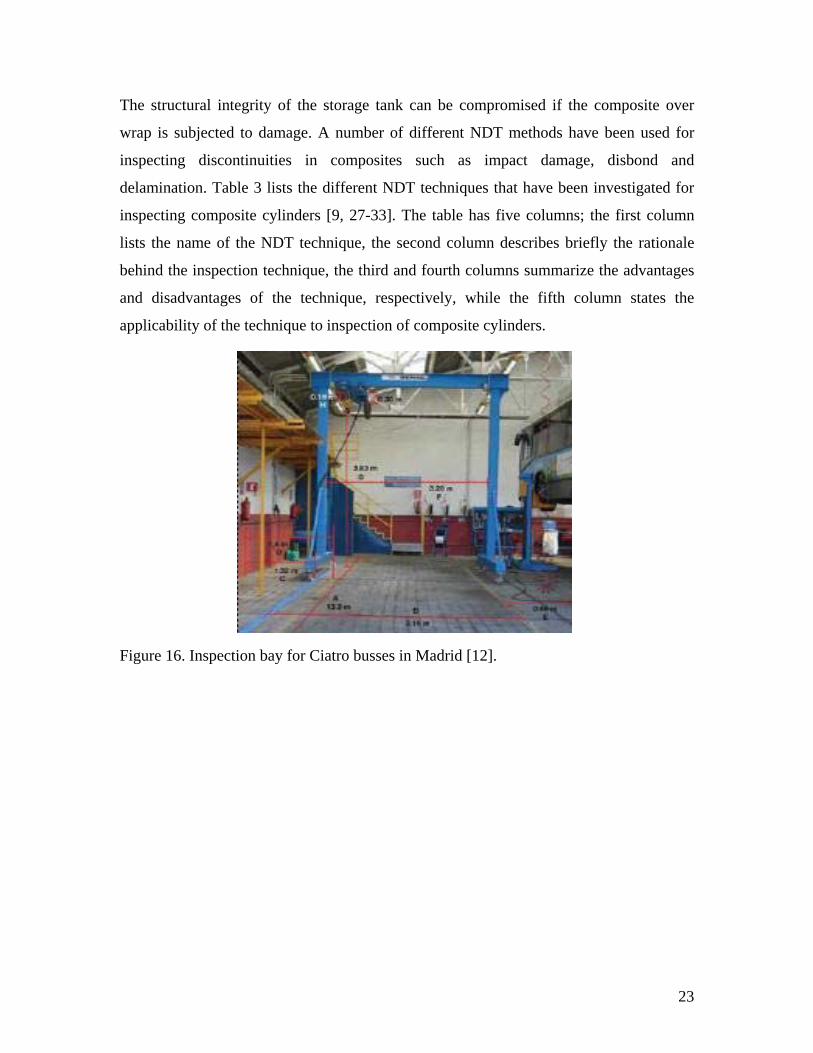
4.3. Nondestructive Testing of Hydrogen Storage Tanks The most popular Nondestructive Testing (NDT) method currently in use for periodic
inspection of the hydrogen fuel tanks, once installed, is visual testing. The vehicle is
periodically brought into an inspection bay, where a human operator visually assesses
any damage that the tank may have suffered. Figure 16 shows a typical inspection bay.
However, even though it is the most convenient and quickest nondestructive method,
involving minimal operator training and data interpretation, it may not be a suitable
testing method under most scenarios.
23
The structural integrity of the storage tank can be compromised if the composite over
wrap is subjected to damage. A number of different NDT methods have been used for
inspecting discontinuities in composites such as impact damage, disbond and
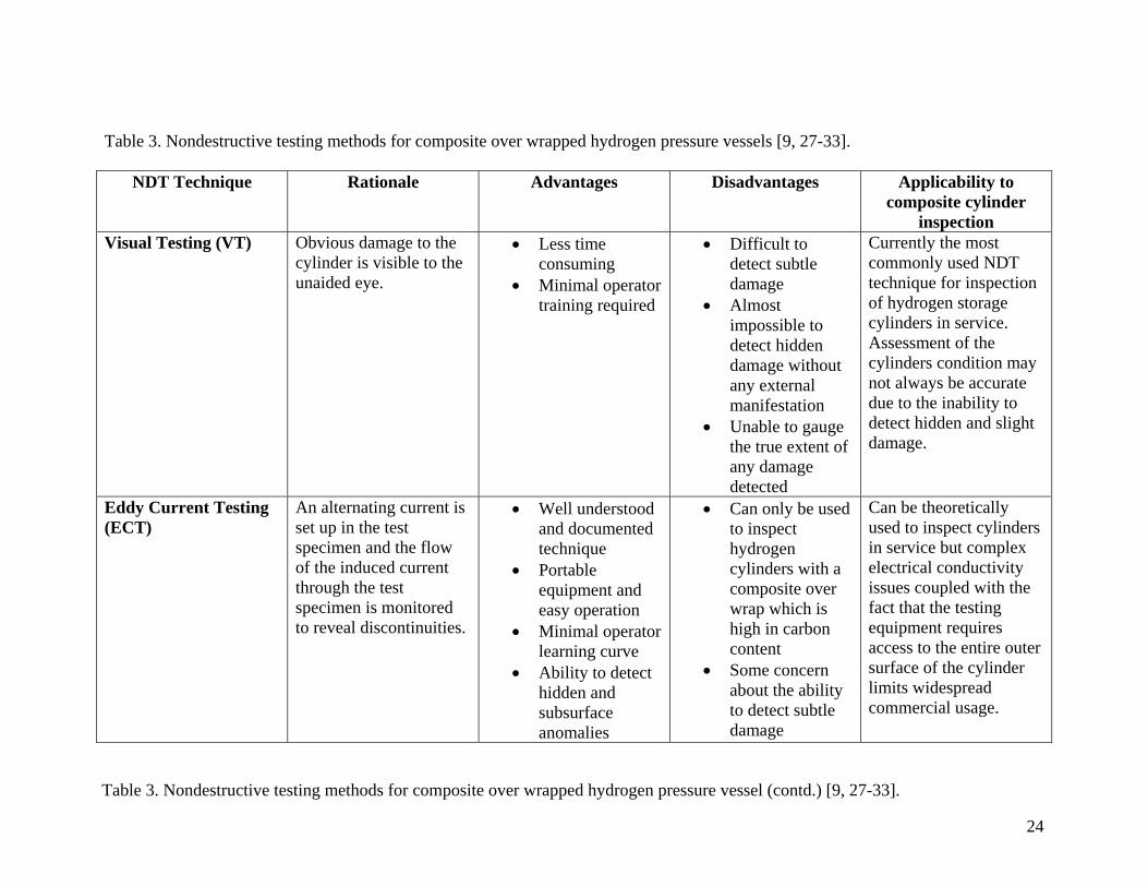
delamination. Table 3 lists the different NDT techniques that have been investigated for
inspecting composite cylinders [9, 27-33]. The table has five columns; the first column
lists the name of the NDT technique, the second column describes briefly the rationale
behind the inspection technique, the third and fourth columns summarize the advantages
and disadvantages of the technique, respectively, while the fifth column states the
applicability of the technique to inspection of composite cylinders.
Figure 16. Inspection bay for Ciatro busses in Madrid [12].
24
Table 3. Nondestructive testing methods for composite over wrapped hydrogen pressure vessels [9, 27-33].
NDT Technique Rationale Advantages Disadvantages Applicability to composite cylinder
inspection Visual Testing (VT) Obvious damage to the
cylinder is visible to the unaided eye.
• Less time consuming
• Minimal operator training required
• Difficult to detect subtle damage
• Almost impossible to detect hidden damage without any external manifestation
• Unable to gauge the true extent of any damage detected
Currently the most commonly used NDT technique for inspection of hydrogen storage cylinders in service. Assessment of the cylinders condition may not always be accurate due to the inability to detect hidden and slight damage.
Eddy Current Testing (ECT)
An alternating current is set up in the test specimen and the flow of the induced current through the test specimen is monitored to reveal discontinuities.
• Well understood and documented technique
• Portable equipment and easy operation
• Minimal operator learning curve
• Ability to detect hidden and subsurface anomalies
• Can only be used to inspect hydrogen cylinders with a composite over wrap which is high in carbon content
• Some concern about the ability to detect subtle damage
Can be theoretically used to inspect cylinders in service but complex electrical conductivity issues coupled with the fact that the testing equipment requires access to the entire outer surface of the cylinder limits widespread commercial usage.
Table 3. Nondestructive testing methods for composite over wrapped hydrogen pressure vessel (contd.) [9, 27-33].
25
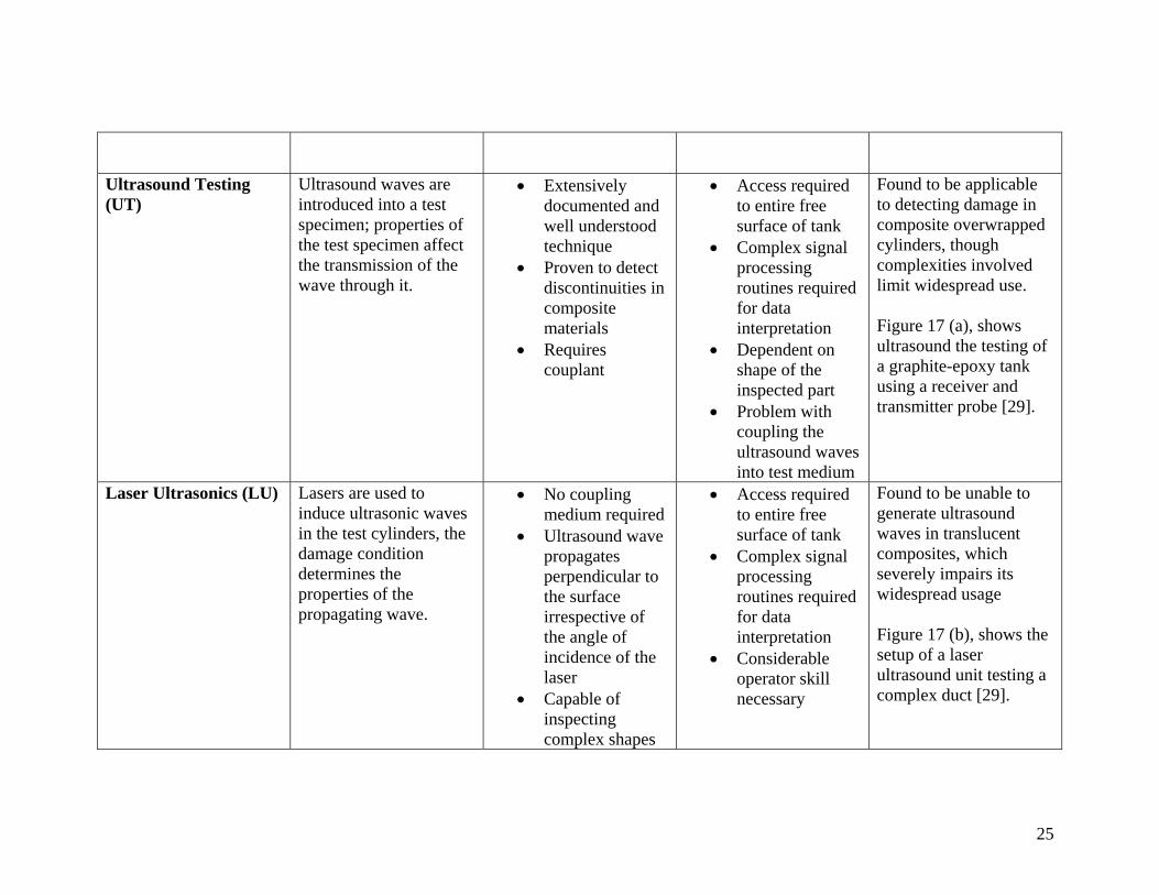
Ultrasound Testing (UT)
Ultrasound waves are introduced into a test specimen; properties of the test specimen affect the transmission of the wave through it.
• Extensively documented and well understood technique
• Proven to detect discontinuities in composite materials
• Requires couplant
• Access required to entire free surface of tank
• Complex signal processing routines required for data interpretation
• Dependent on shape of the inspected part
• Problem with coupling the ultrasound waves into test medium
Found to be applicable to detecting damage in composite overwrapped cylinders, though complexities involved limit widespread use. Figure 17 (a), shows ultrasound the testing of a graphite-epoxy tank using a receiver and transmitter probe [29].
Laser Ultrasonics (LU) Lasers are used to induce ultrasonic waves in the test cylinders, the damage condition determines the properties of the propagating wave.
• No coupling medium required
• Ultrasound wave propagates perpendicular to the surface irrespective of the angle of incidence of the laser
• Capable of inspecting complex shapes
• Access required to entire free surface of tank
• Complex signal processing routines required for data interpretation
• Considerable operator skill necessary
Found to be unable to generate ultrasound waves in translucent composites, which severely impairs its widespread usage Figure 17 (b), shows the setup of a laser ultrasound unit testing a complex duct [29].

26
Critically Reflected Longitudinal Waves (LCR)
LCR waves are sensitive to stress conditions in the propagating medium which in turn are affected by discontinuities present.
Similar to UT • The propagation of LCR waves is affected by factors such as temperature and material texture
• Suffers from some of the same drawbacks as UT
Able to demonstrate ultrasound wave propagation through composite medium, further studies required in order to ascertain the usefulness of this technique for detecting damage in composite cylinders.
Acoustic Emission (AE)
Damaged composites emit acoustic noise when pressurized. Piezoelectric transducers are used to monitor the emitted waves and ascertain extend of damage.
• Global technique • Can be used for
continuous monitoring and dynamic tracking growth of defect growth
• AE transducers are sensitive to stress waves created by a number of different physical phenomenon such as friction, turbulence etc.
• Difficult to separate signal of interest from background noise
• Can only detect active damage
Can be used to inspect cylinders under controlled conditions, might not be possible to use without removing the cylinder from the vehicle. Further research currently being conducted.
Table 3. Nondestructive testing methods for composite over wrapped hydrogen pressure vessel (contd.) [9, 27-33].
27
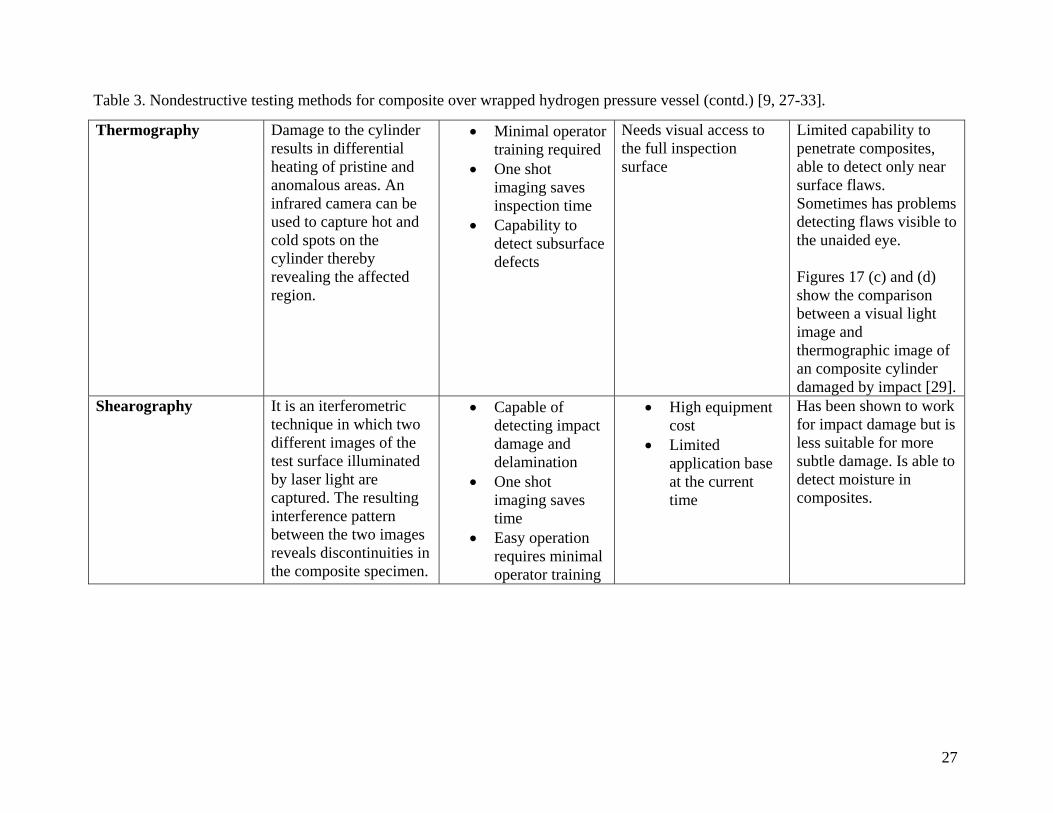
Thermography
Damage to the cylinder results in differential heating of pristine and anomalous areas. An infrared camera can be used to capture hot and cold spots on the cylinder thereby revealing the affected region.
• Minimal operator training required
• One shot imaging saves inspection time
• Capability to detect subsurface defects
Needs visual access to the full inspection surface
Limited capability to penetrate composites, able to detect only near surface flaws. Sometimes has problems detecting flaws visible to the unaided eye. Figures 17 (c) and (d) show the comparison between a visual light image and thermographic image of an composite cylinder damaged by impact [29].
Shearography
It is an iterferometric technique in which two different images of the test surface illuminated by laser light are captured. The resulting interference pattern between the two images reveals discontinuities in the composite specimen.
• Capable of detecting impact damage and delamination
• One shot imaging saves time
• Easy operation requires minimal operator training
• High equipment cost
• Limited application base at the current time
Has been shown to work for impact damage but is less suitable for more subtle damage. Is able to detect moisture in composites.
Table 3. Nondestructive testing methods for composite over wrapped hydrogen pressure vessel (contd.) [9, 27-33].

28
Figure 17. (a) Ultrasound testing of a graphite-epoxy tank using a receiver and transmitter probe, (b) a Lockheed Martin LaserUTTM laser ultrasound unit testing a complex composite duct, (c) visual light image of composite cylinder showing no apparent damage (d) thermographic image of the cylinder in part (c) clearly reveals subsurface damage [30].
(a) (b)
(c) (d)

29
The nondestructive evaluation techniques mentioned in Table 3 cannot be used for online
condition monitoring of the hydrogen fuel cylinders. The cylinder to be inspected for
damage has to be removed from the vehicle and tested under controlled conditions.
However, the composite over wrap that provides the cylinder with its load bearing
capability is light weight and very susceptible to impact damage which may lead to
catastrophic failure of the cylinder without any warning. Therefore, on-line monitoring of
the structural health of the cylinders is of immense practical importance. Table 4 provides
a summary of such techniques employing embedded sensors which are currently under
investigation [33].
Table 4. Health monitoring of composite hydrogen tanks using embedded sensors [33]. Condition Monitoring Scheme
Rationale Applicability to composite hydrogen cylinder inspection
Resistance Strain Gauge Monitoring
Based on the piezo-resistive effect which results in the change in the electrical resistance of a material when mechanical stress is applied
• Traditional method of monitoring strain in the tank shell
• Low cost sensor • Small inspection
area • Needs a large
number of sensors to be integrated into the tank shell
Fiber-optic Strain Gauge Monitoring
It is a fiber-optic based system which uses transmission from one fiber to another in a twisted pair to monitor localized strain.
• Application is limited to localized strain measurements
• High cost involved hinders widespread commercial usage
• Sensitive to environmental noise.
Acousto-Ultrasonic Monitoring
This is a combination of Acoustic-Emission and Ultrasonic monitoring, involving analysis of acoustic-emission events
• Low cost sensor which can monitor large areas of tank surface
• Can be wound into the tank shell structure
• Few real world tests

30
4.4. Design for Inspectability Hydrogen storage tanks currently being used in compact passenger cars as well as larger
vehicles such as busses and trucks are predominantly cylindrical in shape. These tanks
are mostly stowed in the floorboard or the trunk of the smaller cars while busses usually
have an array of roof mounted tanks. The shape of the tanks along with their installation
location on the vehicles makes in-service inspection using traditional NDT techniques
almost impossible.
Some of the changes suggested in order to make in-service inspection of the tanks a
feasible proposition are:
• Design of conformal tanks which can be stowed in more accessible locations on
the vehicle.
• Improved tank design to aid nondestructive testing methods such as ultrasound
testing, which give poor results on test specimen with complex geometries.
• Use of embedded sensors, e.g. optical fiber based sensors, which can be wound
into the matrix of the tanks’ composite over wrap.
• Integrated nondestructive testing in tank manufacturing for improved quality
assurance.

31
5. STANDARDS AND INSPECTION CODES Table 5 provides a summary of the standards and codes for dealing with inspection of hydrogen storage tanks, piping and other parts
of the hydrogen infrastructure [34]. Some of these standards are already in use while the others are currently being developed for use
in the near future.
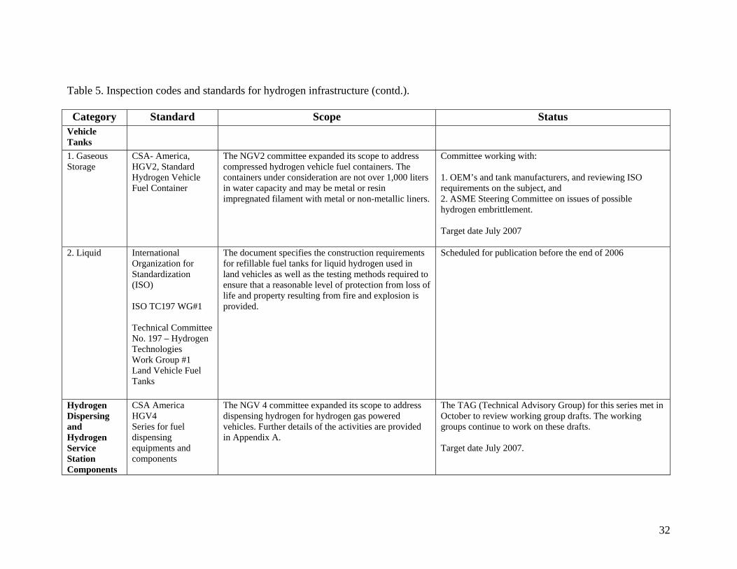
Table 5. Inspection codes and standards for hydrogen infrastructure [34]. Category Standard Scope Status
Transporta-tion Tanks
ASME Boiler and Pressure Vessel Code Section XII
This Section includes transport tanks currently covered under DOT specifications and 49 CFR requirements, specifically, Portable Tanks, Cargo Tanks and Rail Tank Cars.
Published in 2004. It is available through ASME. A “Project Team on Hydrogen Tanks” has been formed and is working to expand this standard to include requirements for hydrogen. The work of this team will also affect Section VIII Divisions 1 and 3, Code Case 2390 and possibly Section X. Key activities include: 1. Fracture resistance requirements, 2. Addition of new materials, 3. Design margins for composite vessels, 4. New code case for composite vessels, 5. Revision of Code Case 2390, 6. Metal hydride vessel design, and 7. Improved methods for in-service inspection.
32
Table 5. Inspection codes and standards for hydrogen infrastructure (contd.). Category Standard Scope Status
Vehicle Tanks
1. Gaseous Storage
CSA- America, HGV2, Standard Hydrogen Vehicle Fuel Container
The NGV2 committee expanded its scope to address compressed hydrogen vehicle fuel containers. The containers under consideration are not over 1,000 liters in water capacity and may be metal or resin impregnated filament with metal or non-metallic liners.
Committee working with: 1. OEM’s and tank manufacturers, and reviewing ISO requirements on the subject, and 2. ASME Steering Committee on issues of possible hydrogen embrittlement. Target date July 2007
2. Liquid International Organization for Standardization (ISO) ISO TC197 WG#1 Technical Committee No. 197 – Hydrogen Technologies Work Group #1 Land Vehicle Fuel Tanks
The document specifies the construction requirements for refillable fuel tanks for liquid hydrogen used in land vehicles as well as the testing methods required to ensure that a reasonable level of protection from loss of life and property resulting from fire and explosion is provided.
Scheduled for publication before the end of 2006
Hydrogen Dispersing and Hydrogen Service Station Components
CSA America HGV4 Series for fuel dispensing equipments and components
The NGV 4 committee expanded its scope to address dispensing hydrogen for hydrogen gas powered vehicles. Further details of the activities are provided in Appendix A.
The TAG (Technical Advisory Group) for this series met in October to review working group drafts. The working groups continue to work on these drafts. Target date July 2007.

33
6. REQUIREMENTS FOR THE HYDROGEN INFRASTRUCTURE
The commercialization of Hydrogen powered vehicles will require the presence of a very
strong supporting infrastructure comprised of hydrogen filling stations, hydrogen
transportation pipelines, facilities for hydrogen storage at generation sites and filling
stations, etc.
Nondestructive testing of the individual components of such an extensive infrastructure is
a more complex and critical problem as compared to the testing of vehicular hydrogen
storage tanks. Separate codes and inspection standards will be required along with a large
number of skilled and semi-skilled operators having a proper understanding of the test
procedures and the capability of interpreting test results. The critical nodes in the overall
infrastructure will need to be identified and monitored closely to ensure smooth operation
of the overall system. An exhaustive list of the existing hydrogen vehicle related codes
and standards, along with the ones which are currently being developed can be found
online at http://www.fuelcellstandards.com/Quick_Reference.htm [34].
The switch to an alternative energy source from a primarily hydrocarbon fuel dependent
social and commercial setup will also have a number of socio-political implications, all of
which are not clear at this point. With the expansion of the hydrogen infrastructure in the
near future a number of these issues will come to the forefront and will have to be dealt
with effectively.

34
7. DEMONSTRATIONS/PROOF OF CONCEPT Field applications of NDT techniques to the inspection of hydrogen pressure vessels or
other components of the hydrogen infrastructure (such as pipelines, hydrogen storage
tanks at filling stations, etc.) have the following principal requirements:
• The inspection process should be completed in a short span of time
• Results generated should be easily displayable on commercially available CRT
and LCD displays
• Operators with minimal training should be able to visually interpret the results
Most of the currently used NDT techniques such as ultrasound testing, eddy current
testing etc. require that the part under inspection be raster scanned so that data for each
scan point can be recorded. Only after the entire test surface has been scanned can a
complete image be displayed. This process is time consuming and inconvenient and may
be unsuitable for most in-service inspections. The following section briefly describes two
innovations that are aimed at tackling the above mentioned drawbacks.
7.1. Laser Ultrasonic Camera This novel camera developed by the researches at the Idaho National Engineering and
Environmental Laboratory (INEEL) has the capability of producing a one shot image of
ultrasonic motions in the sub-nanometers range on the surface of objects at frequencies
ranging from Hz to GHz [35]. The one shot imaging approach produces a full field image
of the entire test area without having to resort to raster scanning, thereby reducing
inspection times drastically. The INEEL laser ultrasonic camera utilizes laser for
ultrasonic generation and a photorefractive approach to interferometry to produce full
field image of ultrasonic motion over a large area. The laser ultrasonic camera provides a
non-contact inspection method which is desirable for most field applications. Appendix B
provides more details on the INEEL laser ultrasonic camera.
7.2. Thermographic Camera A thermographic camera, also sometimes referred to as an infrared camera, produces an
image using infrared radiation [36]. All objects radiate heat naturally and a

35
thermographic camera can be used to capture the differential heat distribution in them to
reveal the presence of discontinuities. The test specimen can also be heated by an
external energy source and then photographed with a thermographic camera [36]. The
one shot imaging approach coupled with the fact that no contact is required with the
object under test makes the thermographic camera a very practical tool for field
applications. Figure 18 shows a handheld thermographic camera.
Figure 18. Handheld thermographic camera [30].
8. VISIT TO LINCOLN COMPOSITES, INC.
A visit was arranged and made to Lincoln Composites on November 20, 2006. The
attendees were: Drs. Erickson and Zoughi from UMR, Dr. Washer and Mr. Blum
(student) from UMC and Mr. Newhouse and Mr. Eihusen from Lincoln Composites, Inc.
the primary purpose of this visit was to observe hydrogen tank manufacturing process
and discuss the NDE methods that may be used for inspection of these tanks.
The tank consists of an HDPE (high-density polyethylene) liner. The tank ends are
manufactured elsewhere and the HDPE is molded around the aluminum boss. The two
ends are plastic-welded to the HDPE pipe that forms the length of the pipe. A
combination of high strength carbon fiber and glass filaments are wound around this
liner. The epoxy resin is applied as the fibers are wound. Three tanks are wound
36
simultaneously on a particular machine. The winding mechanism was designed by
Lincoln Composites and clearly limits their production rate. Though, they have plans to
construct another winding mechanism. A foam piece is placed on the shoulders of the
tank and then a final fiberglass layer is applied. The assembly is cured and then tested
before being painted.
Lincoln Composites also manufactures modules consisting of tanks, pressure relief
valves, piping, and support frame for roof- and chassis-mounting on busses and trucks.
The life span of fiber tanks is 20 years with a 3.3 or 3.5 safety margin (the safety margin
is the design pressure divided by the service pressure). That is the ISO standard. Though
there is some pressure to increase that to 25 years. There is some pressure to reduce the
safety margin as well. The OEM’s are driving for a long-term goal of a 1.8 safety factor,
with a short term goal of 2.5 safety factor. However, a global reduction of 5-10% in the
amount of glass fiber will show a failure in 6 months.
Currently, visual inspection is the NDE method of choice, but they know that not all
failures can be detected visually. One of the engineers related one example of a tank with
a dent that was detected by feel and touch.
NDE has been attempted, but has not shown Lincoln Composites that a failure can exist
blind. In their opinion, on-board NDE could gain 10-15% on the safety margin. NDE is
currently addressing steel bottles, but they do not recommend using these NDE
techniques on composites. In their opinion, an acoustic emission sensor is probably the
best NDE method. One would use a solenoid valve for an actuator and monitor the
acoustic emissions for a leak. Another method of assessing damage is hearing the “tick”
“tink” as the fibers break as the tank is being filled.
Embedded sensors in the tank have been tried by Powertech. Acoustic emission has been
tried by Natural Resources Canada and others have looked at optical glass embedded in

37
the tank. A paper by Robinson addresses the service versus the design pressure and the
reliability of carbon and glass fibers.
38
9. SUMMARY Nondestructive testing is needed for the hydrogen infrastructure in general and
compressed gas hydrogen storage tanks, the current primary form of hydrogen storage, in
particular. Visual testing is the current primary method of testing composite compressed
gas tanks. Eddy current testing, ultrasound testing, laser ultrasonics, critically reflected
longitudinal waves, acoustic emission, thermography, and shearography have all been
studied for use on these tanks. Online condition monitoring has also been proposed using
resistance strain gauge, fiber-optic strain gauge, and acousto-ultrasonic monitoring. No
single nondestructive testing method was found to be able to provide a comprehensive
snapshot of the structural health of the storage tanks. Online condition monitoring using
embedded sensors seems to hold the most promise for the near future. An extensive
collection of standard and codes for manufacturing, testing and maintenance of the
hydrogen infrastructure is a critical requirement. A number of these are being currently
developed for use in the very near future.
39
10. ACKNOWLEDGEMENTS The funding for this work was provided by a grant from the University Transportation
Center (UTC). The authors are grateful to UTC fro providing this opportunity. In
addition, the authors would like t acknowledge the efforts of Professor K. Krishnamurthy
who led this collective effort and continuosly provided leadership and guidance to the
group. We also would like to thank professor G. Washer at the University of Missouri-
Columbia for his insight and inputs to this process.

40
11. BIBLIOGRAPHY
[1] Lincoln Composites (n.d.). “TUFFSHELL® Fuel Tanks Product Information”. Retrieved June 15, 2006 from http://www.lincolncomposites.com/media/LC%20Space%20Age%20PI.pdf. [2] Fuel Cell Today (n.d.). “Quantum Technologies”. Retrieved December 8, 2006 from http://www.fuelcelltoday.com/FuelCellToday/IndustryDirectory/IndustryDirectoryExternal/IndustryDirectoryDisplayCompany/0,1664,395,00.html. [3] J. W. Warner, “Low Cost, High Efficiency, High Pressure Hydrogen Storage”. February 8, 2005. DOE review. Retrieved December 11, 2006 from http://www1.eere.energy.gov/hydrogenandfuelcells/pdfs/04_warner_quantum.pdf. [4] Structural Composites Industries. “Alternative Fuel Cylinders”, 2002. Retrieved December 8, 2006 from http://www.scicomposites.com/alternative_fuel_cylinders.html. [5] Fuel Cell Today (n.d.). “Dynetek Industries Ltd”. Retrieved December 8, 2006 from http://www.fuelcelltoday.com/FuelCellToday/IndustryDirectory/IndustryDirectoryExternal/IndustryDirectoryDisplayCompany/0,1664,271,00.html. [6] Congressman Rick Renzi’s website at http://www.house.gov/list/hearing/az01_renzi/RenziInspectsHydrogen.html. [7] Factsheet on CaFCP Headquarters Hydrogen Fueling Station obtained from the website of California Fuel Cell Partnership, website at http://www.fuelcellpartnership.org/fact_sheets/factsheet_fuelstation.html. [8] Multimedia Hydrogen Fuel Station, Research Penn State, The Online Magazine of The Penn State University. http://www.rps.psu.edu/slides/station03.html. [9] K. Newell, “Low Cost, High Efficiency, High Pressure Hydrogen Storage”, DOE Hydrogen, Fuel Cells and Infrastructure, Technologies Program Review, May 2004. [10] DOE Hydrogen Program, “Roadmap on Manufacturing R&D for the Hydrogen Economy, Draft for Stakeholder/Public Comment”. December 2005. Retrieved August 23, 2006 from http://www.hydrogen.energy.gov/pdfs/roadmap_manufacturing_hydrogen_economy.pdf. [11] Lincoln Composites (n.d.). “TUFFSHELL® Fuel Tanks Product Information”. Retrieved June 15, 2006 from http://www.lincolncomposites.com/media/LC%20Space%20Age%20PI.pdf. [12] Clean Urban Transport for Europe. “Hydrogen Supply Infrastructure and Fuel Cell Bus Technology”, 2004. Retrieved June 5, 2006 from http://www.fuel-cell-bus-

41
club.com/modules/UpDownload/store_folder/Publications/CUTE_Technology_Brochure.pdf. [13] Energy Efficiency and Renewable Energy, U.S. DOE. “Gaseous and Liquid Hydrogen Storage”, April 26, 2006. Retrieved July 27, 2006 from http://www.eere.energy.gov/hydrogenandfuelcells/storage/hydrogen_storage.html. [14] S. Aceves, G. Berry, F. Espinosa, T. Ross, A. Weisberg. “Insulated Pressure Vessels for Vehicular Hydrogen Storage”, May 18, 2006. Retrieved July 31, 2006 from http://www.hydrogen.energy.gov/pdfs/review06/tv_3_aceves.pdf. [15] J. Milliken, J. Petrovic, W. Podolski. “Hydrogen Storage Issues for Automotive Fuel Cells”, November 11-13, 2002. Retrieved July 27, 2006 from http://www.jlab.org/hydrogen/talks/Milliken.pdf. [16] A. W. McClaine et. al. “Hydrogen Transmission/Storage with Metal Hydride-Organic Slurry and Advanced Chemical Hydride/Hydrogen for PEMFC Vehicles”. Retrieved June 7, 2006 from http://www.safehydrogen.com/PDFs/28890o.pdf. [17] T. Yildirim, S. Ciraci, “Titanium-Decorated Carbon Nanotubes as a Potential High-Capacity Hydrogen Storage Medium “,[Electronic Version], 2005. Physical Review Letters, 94.175501. [18] DOE Office of Science. “Report of the Basic Energy Sciences Workshop on Hydrogen Production, Storage, and Use”. May 13-15, 2003. Retrieved August 23, 2006 from http://www.sc.doe.gov/bes/hydrogen.pdf. [19] A. Weisberg, S. Aceves, F. Espinosa, T. Ross, G. Berry, S. Perfect. “Advanced Concepts for Containment of Hydrogen and Hydrogen Storage Materials”, May 18, 2005. Retrieved July 31, 2006 from http://hydrogen.energy.gov/pdfs/review06/stp_36_weisberg.pdf. [20] G. Krainz et al. “Development of Automotive Liquid Hydrogen Storage Systems”, September 26, 2003. Retrieved July 6, 2006 from http://www.storhy.net/pdf/CEC-ICMC_C4-B-02_2003-09-26.pdf. [21] Dynetek Industries Ltd. (n.d.). “CNG Roof Mount System”. Retrieved July 26, 2006 from http://www.dynetek.com/files/roof.pdf. [22] A. Abele “Manufacturing for the Hydrogen Economy”, July 2005. [23]C. Schitter, “New HySafe Project Proposal. Approval of StorHy Cryo Tanks”, March 9, 2006. Retrieved July 6, 2006 from www.hysafe.net/download/609/StorHyproposal.pdf.

42
[24] “Certification Testing and Demonstration of Insulated Pressure Vessels for Vehicular Hydrogen Storage”, complied by the Lawrence Livermore National Laboratory. Proceedings of the 2002 U.S D.O.E Hydrogen Program Review. [25] N. Sirosh, “Hydrogen Composite Tank Program”, 2002. Proceedings of the 2002 U.S. DOE Hydrogen Program Review. [26] F. Mitlitsky, A. H. Weisberg, B. Myers, "Vehicular Hydrogen Storage Using Lightweight Tanks”, Proceedings of the 2000 U.S. DOE Hydrogen Program Review. [27] B. C. Lung, “A Structural Health Monitoring System for Composite Pressure Vessels”. A thesis Submitted to the College of Graduate Studies and Research in Partial Fulfillment of the Requirements for the Degree of Masters of Science in the Department of Mechanical Engineering University of Saskatchewan Saskatoon. [28] O. Erne, T. Waltz, A. Ettemever, “Composite structural NDT with Automatic Stereography Measurements”, online article at www.asnt.org. [29] The Nondestructive Testing Information Analysis Center (NTIAC), “Examination of Nondestructive Evaluation of Composite Gas Cylinders”, Final Report 2002. Prepared for Mark Toughiry, Research and Special Programs Administration, United States Department of Transportation. [30] S. G. LaRiviere, “Introduction to NDT of Composites”, Boeing Commercial Aircraft, Manufacturing , Research and Development. [31] C. Wilkerson, “Acoustic Emission Monitoring of the DC-XA Composite Liquid Hydrogen Tank During Structural Testing”. Marshall Space Flight Center, MSFC, Alabama. [32] “Shearography NDT of Chemical Industry Composites", Laser Technology Inc. [33] J. M. Starbuck and D. L. Beshears, “Smart Onboard Inspection of High Pressure Gas Fuel Cylinders”, Oak Ridge National Laboratory. [34] Hydrogen Standards and Codes at http://www.fuelcellstandards.com/Quick_Reference.htm. [35] INEEL Ultrasonic Camera, Online Fact sheet obtained from Idaho National Laboratory at http://www.inl.gov/factsheets/industrial/ultrasoniccamera.pdf [36] The Thermographic Camera at the online encyclopedia www.wikipedia.org.
43
Appendix A
Details of the various projects under the NGV4 committee involved in developing codes
and standards for Hydrogen Dispensing and Hydrogen Service Components are provided
below [34].
HGV 4.1 Hydrogen Dispensers This standard contains safety requirements for the material, design, manufacture and
testing of gaseous hydrogen dispensers constructed entirely of new unused parts and
materials. This standards does not apply to the nozzle; vehicle to station communication,
compression and ancillary equipment, compressed hydrogen gas storage containers,
vehicle fueling appliances for HGV, remote station or kiosk consoles and remote
sequencing equipment and other remote equipment not supplied as part of the dispenser.
HGV 4.2 Hose and Hose Assemblies for Hydrogen Vehicles and Dispensing Systems This standard contains safety requirements for the material. Design, manufacture and
testing of gaseous hydrogen hose and hose assemblies which are used for (1) connecting
the dispenser to the refueling nozzle, (2) use as part of a vehicle on-board fuel system, or
93) use as vent lines which carry gas to a safe location for either vehicle or dispensing
systems.
HGV 4.3 Temperature Compensation Devices for Hydrogen Dispensing Systems This standard details safety performance requirements for gaseous hydrogen fueling
station fueling station temperature compensation devices systems. It applies to newly
manufactured systems designed primarily to adjust for full fill and to avoid over-
pressurization of vehicle fuel storage containers under the operating temperature
conditions specified in the standard. This standard does not apply to onboard vehicle
temperature compensation systems or components.

44
HGV 4.4 Breakaway Devices for Hoses Used in Hydrogen Vehicle Fueling Stations This standard contains safety requirements for the material, design, manufacture and
testing of newly manufactured fueling hose breakaway devices. This is not applicable to
“Vehicle Refueling Appliances,” Dispenser Breakaway Devices or Vehicle Breakaway
Components.
HGV 4.5 Priorities and Sequencing Equipment for Gaseous Hydrogen Dispensing Systems This standard applies to priority and sequencing equipment which are part of a gaseous
hydrogen vehicle fueling system. This standard contains safety requirements for the
design, manufacture and testing of the priority and sequencing systems for gaseous
hydrogen dispensers which are designed primarily to provide compressed hydrogen for
vehicle fueling stations. This standard does not apply to the pressure swing absorber
sequencing panel or the gas dryer sequencing panel.
HGV 4.6 Manually Operated Valves Used in Gaseous Hydrogen Vehicle Fueling Stations This standard contains safety requirements for the design, manufacture and testing of
manually operated valves for gaseous hydrogen vehicle fueling stations. This standard
does not apply to fuel storage container shut-off valves or fueling nozzle valves.
HGV 4.7 Automatic Pressure Operated Valves for Use in Gaseous Hydrogen Vehicle Fueling Stations This standard contains safety requirements for the design, manufacture and testing of
automatic, pressure operated valves used in gaseous hydrogen vehicle fueling stations.
This standard does not apply electrically actuated valves, hydraulically actuated valves,
pressure regulating valves, pressure relief valves or fueling nozzle valves.

45
HGV 4.8 Hydrogen Gas vehicle Fueling Stations Compressor This standard contains safety requirements for the design, manufacture and testing of
gaseous hydrogen compressor packages used in fueling station service. This standard
applies to newly manufactured equipment designed primarily to provide compressed
hydrogen for vehicle fueling stations. This standard does not apply to vehicle fueling
appliances for HGV or compressor packages used for non-vehicular fuel appliances
46
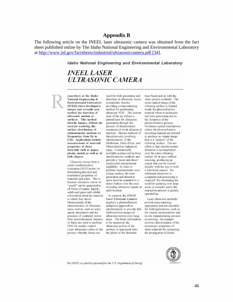
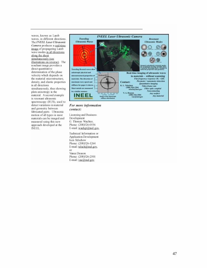
Appendix B The following article on the INEEL laser ultrasonic camera was obtained from the fact sheet published online by The Idaho National Engineering and Environmental Laboratory at http://www.inl.gov/factsheets/industrial/ultrasoniccamera.pdf [34].
47