utas service manual with uba-4204 version 1.3 · 2011-04-15 · version 1.3 page 2 of 41 ♦ the...
TRANSCRIPT

Version 1.1 Page 49 of 47
UTAS Visual Electrodiagnostic
System with EM for Windows
Service Manual
Version 1.3
April 20, 2009
0086

Version 1.3 Page ii of 41
LKC Technologies, Inc.
2 Professional Drive Suite 222
Gaithersburg, MD 20879 301.840.1992 800.638.7055
301.330.2237 (fax) [email protected]
www.LKC.com
Copyright © 2007, LKC Technologies. All Rights Reserved
WARRANTY
LKC Technologies, Inc. unconditionally warrants this instrument to be free from defects in materials
and workmanship, provided there is no evidence of abuse or attempted repairs without authorization
from LKC Technologies, Inc. This Warranty is binding for one year from date of installation and is
limited to: servicing and/or replacing any instrument, or part thereof, returned to the factory for that
purpose with transportation charges prepaid and which are found to be defective. This Warranty is
made expressly in lieu of all other liabilities and obligations on the part of LKC Technologies, Inc.
DAMAGE UPON ARRIVAL. Each instrument leaves our plant, after rigorous tests, in perfect
operating condition. The instrument may receive rough handling and damage in transit. The shipment
is insured against such damage. The Buyer must immediately report, in writing, any concealed or
apparent damage to the last carrier. Report any damage also to us, and issue an order for replacement or
repair.
DEFECTS OCCURRING WITHIN WARRANTY PERIOD. Parts of units may develop defects
which no amount of initial testing will reveal. The price of our instruments makes provision for such
service, but it does not:
1. Provide for transportation charges to our factory for service,
2. Provide for services not performed or authorized by us,
3. Provide for the cost of repairing instruments that have obviously been abused or subjected to
unusual environments for which they have not been designed.
We will be happy at any time to discuss by phone, letter, FAX, or e-mail suspected defects or
aspects of instrument operation that may be unclear. We advise you to inform us by phone, letter, FAX,
or e-mail of the nature of the defect before returning an instrument for repair. Many times a simple
suggestion will solve the problem without returning an instrument to the factory. If we are unable to
suggest something that solves the problem, we will advise you as to what parts of the equipment should
be returned to the factory for service.

Version 1.3 Page iii of 41
DEFECTS OCCURRING AFTER WARRANTY PERIOD. Charges for repairs after the warranty
period will be based upon actual hours spent on the repair at the then prevailing rate, plus cost of parts
required and transportation charges; or you may elect to purchase an extended warranty.
We will be happy to discuss by phone, letter, FAX, or e-mail any problem you may be experiencing.
SOFTWARE LICENCE
The UTAS software is a copyrighted product of LKC Technologies, Inc. and is included with the UTAS
system under the following license agreement:
The software may be used in conjunction with the UTAS system only. The purchaser of the
UTAS system may make copies of the software for convenience of use, provided the LKC
copyright notice is preserved with each copy. This license specifically prohibits the use of this
software in a system that does not include an LKC Technologies, Inc. UTAS Interface Unit.
Additional copies of the software may be purchased to produce reports of UTAS data using a
stand-alone computer system.
LKC Technologies, Inc.
Customer Service/Support
800.638.7055 (US & Canada) 301.840.1992 (Worldwide)
301.330.2237 (FAX)
www.LKC.com

Version 1.3 Page iv of 41
INTRODUCTION
LKC’s UTAS visual electrodiagnostic test system is designed for
electroretinogram (ERG), visually evoked response (VER), and electro-oculogram (EOG
testing. It can also be upgraded with additional software allowing for multifocal ERG,
multifocal VEP and Sweep VEP testing. Those last three are covered in different
manuals. The UTAS is a fully automated system providing the featured needed for both
clinical and research applications. The UTAS meets all the specifications and
requirements of the International Society for the Clinical Electrophysiology of Vision
(ISCEV).
This Hardware Manual covers setting up and calibrating the equipment. This
equipment is offered for sale only to qualified Health Professionals. The improper use of
this equipment may be injurious to the patient.
Please note that not all system configurations include every hardware
component described in this manual.

Version 1.3 Page v of 41
INTRODUCTION.................................................................................................................................... iv
1.0 Introduction............................................................................................................................... 1
1.1 Overview ................................................................................................................................ 1
1.2 Safety ...................................................................................................................................... 1
1.3 Use .......................................................................................................................................... 1
1.4 Essential Performance .......................................................................................................... 1
1.5 Precautions ............................................................................................................................ 1
1.6 Special Precautions Concerning EMC................................................................................ 3
1.7 Warning ................................................................................................................................. 7
1.8 Symbols .................................................................................................................................. 7
1.9 Approvals............................................................................................................................... 8
1.10 European Representative ..................................................................................................... 9
2.0 Functional Description ........................................................................................................... 10
2.1 UTAS System Quick Specs................................................................................................. 10
2.2 Computer and Associated Devices .................................................................................... 12
2.3 System Interface.................................................................................................................. 12
2.4 UBA-4204 Patient Amplifier and Interface ...................................................................... 13
2.4.1 UBA-4204 controls....................................................................................................... 13
2.4.2 UBA-4204 Inputs.......................................................................................................... 14
2.4.3 Battery Charging........................................................................................................... 14
2.4.4 Changing The Battery................................................................................................... 15
2.5 Ganzfeld ............................................................................................................................... 16
2.5.1 Sunburst........................................................................................................................... 16
2.5.2 BigShot ............................................................................................................................. 17
2.6 Pattern Monitor .................................................................................................................. 17
2.7 CMGS-1 Color Mini-Ganzfeld Stimulator (optional) ..................................................... 18
2.8 MGS-2 White-Only Mini-Ganzfeld (optional) ................................................................. 18
2.9 Overall Equipment Interrelations ..................................................................................... 18
3.0 Setting Up the System ............................................................................................................. 22
3.1 Inventory.............................................................................................................................. 22
3.2 Precautions .......................................................................................................................... 22
3.2.1 Power Main Interference............................................................................................... 22
3.2.2 High Frequency Electrical Noise .................................................................................. 23
3.2.3 Shielding ....................................................................................................................... 23
3.3 Equipment Interconnections.............................................................................................. 23
4.0 Before You Use the System .................................................................................................... 26
5.0 Checking UBA-4204 (Amplifier) Response .......................................................................... 27
6.0 Checking Ganzfeld Calibration (for Sunburst and BigShot) ............................................. 28
6.1 Overview .............................................................................................................................. 28
6.2 Checking Calibration Using Zenith Software ( for SunBurst Only).............................. 29
6.3 Checking Calibration On Your Own ................................................................................ 31
Version 1.3 Page vi of 41
6.3.1 Checking Calibration of Dim White LED .................................................................... 31
6.3.2 Checking Calibration of Xenon Flash........................................................................... 31
6.3.3 Checking Calibration of Color LEDs ........................................................................... 31
6.4 Replacing Background or Flash Lamps/LEDs ................................................................ 31
7.0 External Triggers (Input and Output) .................................................................................. 32
7.1 Triggering External Equipment – Trigger Out ............................................................... 32
7.2 Receiving Triggers from External Equipment – Trigger In ........................................... 32
8.0 Cleaning The System Between Patients ................................................................................ 33
8.1 Cleaning Reusable Burian-Allen Contact Lens Electrodes ............................................ 33
8.2 Cleaning the Forehead Rest ............................................................................................... 33
9.0 Troubleshooting Guide............................................................................................................... 34 8.1 Computer Boot-up .................................................................................................................. 34
8.2 Computer Monitor.................................................................................................................. 34
8.3 Keyboard ................................................................................................................................. 34
8.4 Mouse ....................................................................................................................................... 34
8.6 Printer ...................................................................................................................................... 35
8.7 Ganzfeld ................................................................................................................................... 35
8.8 Data .......................................................................................................................................... 35
8.9 Mini-ganzfeld........................................................................................................................... 35
8.10 Interference ............................................................................................................................. 36
Appendix 1: Artifacts in Electrophysiological Testing........................................................................ 37

Version 1.3 Page 1 of 41
1.0 Introduction
1.1 Overview
The Hardware Manual will explain how your system is connected together, the specifications for
the system, how to use the hardware features, and how to assist LKC in servicing your system
should trouble arise. Subsequent sections, the Software Manual and the Testing manual will
explain how to use the software and the details of performing a test.
1.2 Safety
The equipment has been tested in accordance with IEC EN60601-1-2:2001 and meets all
requirements for type B Patient Connections.
1.3 Use
The LKC UTAS Visual Electrodiagnostic Testing System is an ophthalmic evoked potential
system. Its function is to elicit electrical responses from the retina and visual pathways for
diagnostic purposes.
The UTAS is designed for the electroretinogram (ERG), electro-oculogram (EOG), visual
evoked potential (VEP), sweep VEP and multi-focal ERG tests. These tests are useful in the
diagnosis of a wide range of visual disorders.
The system also has the capability to run multi-focal electroretinogram (mfERG) and multi-focal
visual evoked potentials (mfVEP) and sweep visually evoked potential (SVEP) tests. A UV
stimulus add-on is also possible on BigShot ganzfeld. These tests can be purchased as options
(contact LKC for availability), and are discussed in detail in separate user’s manuals.
This equipment is offered for sale only to qualified Health Professionals. The improper use of
this equipment may be injurious to the patient.
1.4 Essential Performance
♦ Correct operation of system components, including visual stimuli, i.e. flash, flicker, fixation,
background light and pattern stimulus; data acquisition; data analysis and test result display.
♦ Accuracy of intensity and timing of various visual stimuli.
♦ Accuracy of patient amplifier gain, and data acquisition timing.
♦ Accuracy of data analysis and result display.
1.5 Precautions
♦ All servicing of this equipment is to be performed by LKC Technologies, Inc. or by a service
center approved by LKC Technologies, Inc.
♦ Only equipment supplied by LKC Technologies, Inc. shall be plugged into the 115V~ outlets
at the back of the MGIT-100.

Version 1.3 Page 2 of 41
♦ The UTAS needs special precautions regarding EMC and needs to be installed and put into
service according to the EMC information provided in the User’s Manual.
♦ Portable and mobile RF communications equipment can affect the UTAS performances.
♦ Input overload can occur with defibrillator or electrocautery if used in the operating room.
♦ Any device connected to this system must be explicitly approved by LKC Technologies, Inc.
and must meet the relevant requirements of IEC60601-1.
♦ The use of any accessories or replacement of components other than those supplied by or
approved by LKC Technologies, Inc. may compromise patient safety.
♦ Eye infections may result from use of non-sterilized contact-lens electrodes.
♦ The forehead rest should be cleaned and disinfected after each patient.
♦ This device is not protected against the ingress of water and should not be used in the
presence of liquids which may enter the device.
♦ This device is not suitable for use in the presence of a flammable anesthetic mixture of air, or
with oxygen or nitrous oxide.
♦ Replacement AC fuses shall only be - T2.5A 250V (Slow-Blow) for 210-230 volt power-line
countries, and T5.0A 250V (Slow-Blow) for 100 – 120 volt power-line countries.
♦ This is an EU/MDD class I device requiring a three pronged grounded outlet.
♦ The UTAS system is an FDA Class II medical device that incorporates an IBM-compatible
personal computer. To ensure patient safety, the personal computer and all of its peripherals
are powered from an isolation transformer, through the power receptacles on the back of the
MGIT-100. All devices connected to the computer must be powered from these isolated
power receptacles. Failure to observe this precaution may endanger patient safety and will
void your warranty. LKC Technologies, Inc. will not service a system whose computer is
connected to external devices, nor will it give permission for others to service such a system.
♦ Examples of improper connections include connecting the UTAS computer (whether
supplied by LKC or by another party) to a laser printer, or to any other device that is plugged
into a wall outlet or that is connected to another device that is plugged into a wall outlet (such
as a printer sharing unit connected to another computer). If you have specific questions on
this matter, please contact LKC Technologies, Inc. for advice.
♦ Ensure the amplifier unit battery is fully charged prior to use.
♦ A fully charged battery will provide 12+ hours of useable recording time.

Version 1.3 Page 3 of 41
♦ Do not record while amplifier is recharging! This will compromise the quality of recordings
and subject isolation.
1.6 Special Precautions Concerning EMC
Guidance and manufacturer’s declaration – electromagnetic emissions
The UTAS is intended for use in the electromagnetic environment specified below. The customer or the user of the UTAS should assure that it is used in such an environment.
Emissions test Compliance Electromagnetic environment – guidance
RF emissions CISPR 11
Group 1
The UTAS uses RF energy only for its internal function. Therefore, its RF emissions are very low and are not likely to cause any interference in nearby electronic equipment.
RF emissions CISPR 11
Class A
Harmonic emissions IEC 61000-3-2
Class A
Voltage fluctuations/ flicker emissions IEC 61000-3-3
Complies
The UTAS is suitable for use in all establishments other than domestic and those directly connected to the public low-voltage power supply network that supplies buildings used for domestic purposes.
Warning: The UTAS system should not be used adjacent to or stacked with other equipment
and if adjacent or stacked use is necessary, the UTAS should be observed to verify normal
operation in the configuration in which it will be used.
Guidance and manufacturer’s declaration – electromagnetic immunity
The UTAS is intended for use in the electromagnetic environment specified below. The customer or the user of the UTAS should assure that it is used in such an environment.
Immunity test IEC 60601 test level
Compliance level Electromagnetic environment –
guidance
Electrostatic discharge (ESD) IEC 61000-4-2
±6 kV contact ±8 kV air
±6 kV contact ±8 kV air
Floors should be wood, concrete or ceramic tile. If floors are covered with synthetic material, the relative humidity should be at least 30 %.

Version 1.3 Page 4 of 41
Electrical fast transient/burst IEC 61000-4-4
±2 kV for power supply lines ±1 kV for input/output lines
±2 kV for power supply lines ±1 kV for input/output lines
Mains power quality should be that of a typical commercial or hospital environment.
Surge IEC 61000-4-5
±1 kV line(s) to line(s) ±2 kV line(s) to earth
±1 kV line(s) to line(s) ±2 kV line(s) to earth
Mains power quality should be that of a typical commercial or hospital environment.
Voltage dips, short interruptions and voltage variations on power supply input lines IEC 61000-4-11
<5 % UT (>95 % dip in UT) for 0,5 cycle 40 % UT (60 % dip in UT) for 5 cycles 70 % UT (30 % dip in UT) for 25 cycles <5 % UT (>95 % dip in UT) for 5 sec
<5 % UT (>95 % dip in UT) for 0,5 cycle 40 % UT (60 % dip in UT) for 5 cycles 70 % UT (30 % dip in UT) for 25 cycles <5 % UT (>95 % dip in UT) for 5 sec
Mains power quality should be that of a typical commercial or hospital environment. If the user of the UTAS requires continued operation during power mains interruptions, it is recommended that the UTAS be powered from an uninterruptible power supply or a battery.
Power frequency (50/60 Hz) magnetic field IEC 61000-4-8
3 A/m 3 A/m
Power frequency magnetic fields should be at levels characteristic of a typical location in a typical commercial or hospital environment.
NOTE UT is the a.c. mains voltage prior to application of the test level.
Version 1.3 Page 5 of 41
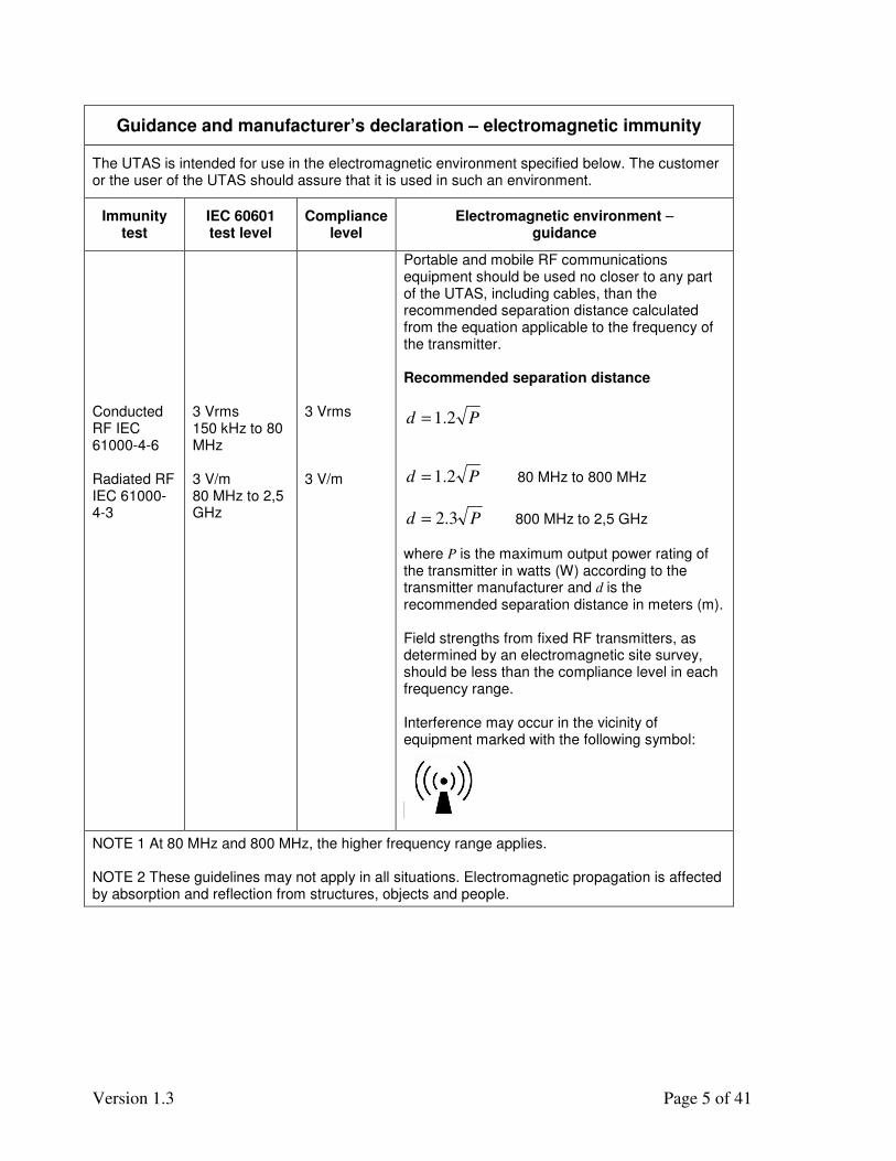
Guidance and manufacturer’s declaration – electromagnetic immunity
The UTAS is intended for use in the electromagnetic environment specified below. The customer or the user of the UTAS should assure that it is used in such an environment.
Immunity test
IEC 60601 test level
Compliance level
Electromagnetic environment – guidance
Conducted RF IEC 61000-4-6 Radiated RF IEC 61000-4-3
3 Vrms 150 kHz to 80 MHz 3 V/m 80 MHz to 2,5 GHz
3 Vrms 3 V/m
Portable and mobile RF communications equipment should be used no closer to any part of the UTAS, including cables, than the recommended separation distance calculated from the equation applicable to the frequency of the transmitter. Recommended separation distance
Pd 2.1=
Pd 2.1= 80 MHz to 800 MHz
Pd 3.2= 800 MHz to 2,5 GHz
where P is the maximum output power rating of the transmitter in watts (W) according to the transmitter manufacturer and d is the recommended separation distance in meters (m). Field strengths from fixed RF transmitters, as determined by an electromagnetic site survey, should be less than the compliance level in each frequency range. Interference may occur in the vicinity of equipment marked with the following symbol:
NOTE 1 At 80 MHz and 800 MHz, the higher frequency range applies. NOTE 2 These guidelines may not apply in all situations. Electromagnetic propagation is affected by absorption and reflection from structures, objects and people.

Version 1.3 Page 6 of 41
a) Field strengths from fixed transmitters, such as base stations for radio (cellular/cordless) telephones and land mobile radios, amateur radio, AM and FM radio broadcast and TV broadcast cannot be predicted theoretically with accuracy. To assess the electromagnetic environment due to fixed RF transmitters, an electromagnetic site survey should be considered. If the measured field strength in the location in which the UTAS is used exceeds the applicable RF compliance level above, the UTAS should be observed to verify normal operation. If abnormal performance is observed, additional measures may be necessary, such as reorienting or relocating the UTAS. b) Over the frequency range 150 kHz to 80 MHz, field strengths should be less than 3 V/m.
Recommended separation distances between portable and mobile RF communications equipment and the UTAS
The UTAS is intended for use in an electromagnetic environment in which radiated RF disturbances are controlled. The customer or the user of the UTAS can help prevent electromagnetic interference by maintaining a minimum distance between portable and mobile RF communications equipment (transmitters) and the UTAS as recommended below, according to the maximum output power of the communications equipment.
Separation distance according to frequency of transmitter m
Rated maximum output power of transmitter
W
150 kHz to 80 MHz
Pd 2.1=
80 MHz to 800 MHz
Pd 2.1=
800 MHz to 2,5 GHz
Pd 3.2=
0.01 0.12 0.12 0.23
0.1 0.38 0.38 0.73
1 1.2 1.2 2.3
10 3.8 3.8 7.3
100 12 12 23
For transmitters rated at a maximum output power not listed above, the recommended separation distance d in meters (m) can be estimated using the equation applicable to the frequency of the transmitter, where P is the maximum output power rating of the transmitter in watts (W) according to the transmitter manufacturer. NOTE 1 At 80 MHz and 800 MHz, the separation distance for the higher frequency range applies. NOTE 2 These guidelines may not apply in all situations. Electromagnetic propagation is affected by absorption and reflection from structures, objects and people.
Version 1.3 Page 7 of 41
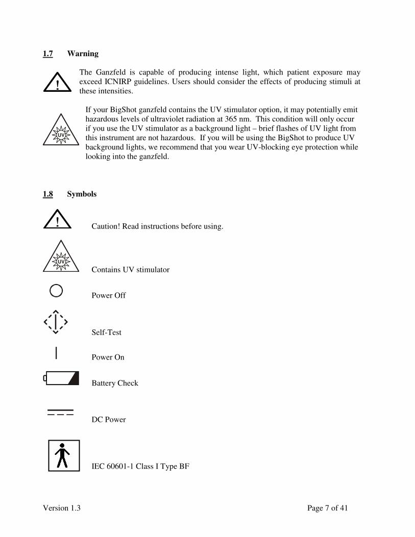
1.7 Warning
The Ganzfeld is capable of producing intense light, which patient exposure may
exceed ICNIRP guidelines. Users should consider the effects of producing stimuli at
these intensities.
If your BigShot ganzfeld contains the UV stimulator option, it may potentially emit
hazardous levels of ultraviolet radiation at 365 nm. This condition will only occur
if you use the UV stimulator as a background light – brief flashes of UV light from
this instrument are not hazardous. If you will be using the BigShot to produce UV
background lights, we recommend that you wear UV-blocking eye protection while
looking into the ganzfeld.
1.8 Symbols
Caution! Read instructions before using.
UV
Contains UV stimulator
Power Off
Self-Test
Power On
Battery Check
DC Power
IEC 60601-1 Class I Type BF
UV

Version 1.3 Page 8 of 41
IEC 60601-1 Class I Type B
Fuse Rating: “T2.5A 250V” is for 210-230 VAC power-line countries
“T5.0A 250V” is for 100-120 VAC power-line countries
Volts AC
Council Directive Compliance
Earth ground connection point, functional earth terminal
Chassis ground, protective earth terminal
1.9 Approvals
This product has been tested for EMI and complies with the requirements of EN 60601-1-
1-2:2001 (Group 1 Class A device under CISPR 11). Use of this equipment in the vicinity of
other equipment with excessive EMI may interfere with the proper operation of this product.
This product conforms to IEC601-1:1988 with Amendments A1:1991 and A2:1995, and
to EN60601-1:1990.
This product has been tested in accordance with AAMI Safe Current Limits Standard and
meets all requirements for direct patient connection. The product is an AC line powered device
designed to meet the applicable requirements of UL 60601-1 Standard for Safety (Medical and
Dental Equipment). This device should only be used according to the manufacturer’s instructions
and by qualified health professionals.
This product has been approved for both CE and CB certificates
0086
T2.5A 250V Or T5.0A 250V

Version 1.3 Page 9 of 41
1.10 European Representative
Emergo Europe Symbol
Molenstraat 15
2513 BH The Hague
The Netherlands
Tel: +31 70-345-8570
Fax: +31 70-346-7299
Version 1.3 Page 10 of 41
2.0 Functional Description
In this section, the function of each equipment group is explained and a block diagram is
discussed which shows equipment interrelationships. The UTAS system can either come with a
Sunburst Ganzfeld (fits most primate faces and small animals) or the BigShot Ganzfeld which is
designed for larger animals and humans. The BigShot ganzfeld can be upgraded with a UV
stimulator.
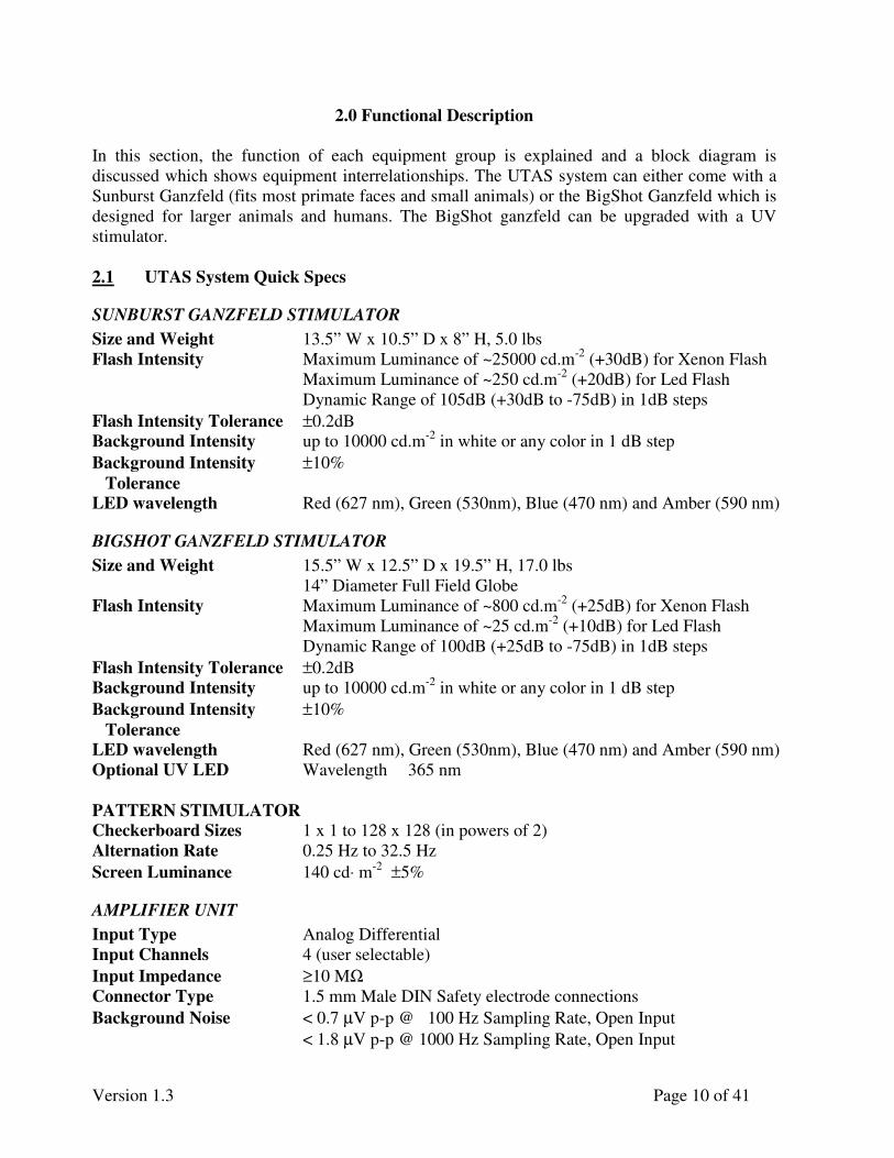
2.1 UTAS System Quick Specs
SUNBURST GANZFELD STIMULATOR
Size and Weight 13.5” W x 10.5” D x 8” H, 5.0 lbs
Flash Intensity Maximum Luminance of ~25000 cd.m-2
(+30dB) for Xenon Flash
Maximum Luminance of ~250 cd.m-2
(+20dB) for Led Flash
Dynamic Range of 105dB (+30dB to -75dB) in 1dB steps
Flash Intensity Tolerance ±0.2dB
Background Intensity up to 10000 cd.m-2
in white or any color in 1 dB step
Background Intensity ±10%
Tolerance
LED wavelength Red (627 nm), Green (530nm), Blue (470 nm) and Amber (590 nm)
BIGSHOT GANZFELD STIMULATOR
Size and Weight 15.5” W x 12.5” D x 19.5” H, 17.0 lbs
14” Diameter Full Field Globe
Flash Intensity Maximum Luminance of ~800 cd.m-2
(+25dB) for Xenon Flash
Maximum Luminance of ~25 cd.m-2
(+10dB) for Led Flash
Dynamic Range of 100dB (+25dB to -75dB) in 1dB steps
Flash Intensity Tolerance ±0.2dB
Background Intensity up to 10000 cd.m-2
in white or any color in 1 dB step
Background Intensity ±10%
Tolerance
LED wavelength Red (627 nm), Green (530nm), Blue (470 nm) and Amber (590 nm)
Optional UV LED Wavelength 365 nm
PATTERN STIMULATOR
Checkerboard Sizes 1 x 1 to 128 x 128 (in powers of 2)
Alternation Rate 0.25 Hz to 32.5 Hz
Screen Luminance 140 cd⋅ m-2
±5%
AMPLIFIER UNIT
Input Type Analog Differential
Input Channels 4 (user selectable)
Input Impedance ≥10 MΩ
Connector Type 1.5 mm Male DIN Safety electrode connections
Background Noise < 0.7 µV p-p @ 100 Hz Sampling Rate, Open Input
< 1.8 µV p-p @ 1000 Hz Sampling Rate, Open Input

Version 1.3 Page 11 of 41
CMRR > 100 dB at 50 – 60 Hz
Frequency Range DC to > 1.0 MHz without aliasing. High frequency cutoff depends
on sampling rate.
Input Gain 1, 2, 4, 8, 16, 32, 64 (user selectable)
DC Input Range ±2 V (Gain = 1)
Stability < 250 nV / °C drift
Accuracy < 0.2% absolute, Nonlinearity < 0.0010%
Calibration Automatic gain and offset calibration on demand
Data Resolution 0.25 µV / bit (Gain = 1) to 3.7 nV / bit (Gain = 64)
Sampling Rate 5 Hz to 3750 Hz
Data Connection Bidirectional fiber optic cable (TOSlink) to UBA-4204 interface
Safety < 1 nA Leakage Current; > 10 kV Isolation when operated
according to instructions
Power Source Rechargeable Li-Ion Battery
Battery Charger 100-240 V 50/60 Hz, 12 V 1.0 A (included)
Operating Time Up to 12 hours of continuous use before recharging
Recharge Time 4 hours to 80% capacity, 8 hours to 100%
Environmental 0° C to 55° C (32° F to 131° F)
Size 5¾” x 3¼” x 1” (14.6 cm x 8.3 cm x 2.5 cm)
Weight 8 oz. (225 g), including battery
SYSTEM INTERFACE UNIT
Computer Interface USB 1.1 + RS-232
Power Source 100-240 VAC 100W
Size 10” x 10” x 4”
Weight 6.5 lb
UBA-4204 INTERFACE
Computer Interface USB 1.1
Power Source USB Powered
Size 6” x 3” x 2¼“(15 cm x 7.6 cm x 5.7 cm)
Weight 8oz (225g)
POWER REQUIREMENTS
Input Voltage 100/115/230 VAC ±10%
Input Frequency 47 to 63Hz
Power Consumption 520 watts maximum
OPERATING ENVIRONMENT Operating Temperature 5° to 35°C
Humidity 15% to 80% RH non-condensing
Storage Temperature -10° to 70°C
Version 1.3 Page 12 of 41
2.2 Computer and Associated Devices
The computer is either a desktop or notebook PC with a minimum of 1.8 GHz CPU speed 448
MB of Random Access Memory (RAM), at least 80GB hard disk drive, and a rewritable CD
drive. The computer provides the control of all test and analysis operations.
An additional video card is added to the computer by LKC. This video board sends video signal
to the operator’s LCD monitor.
2.3 System Interface
The system interface contains:
♦ 24V Medical Grade Power Supply
♦ Interface printed circuit board
♦ A custom ordered toroidal transformer
Version 1.3 Page 13 of 41
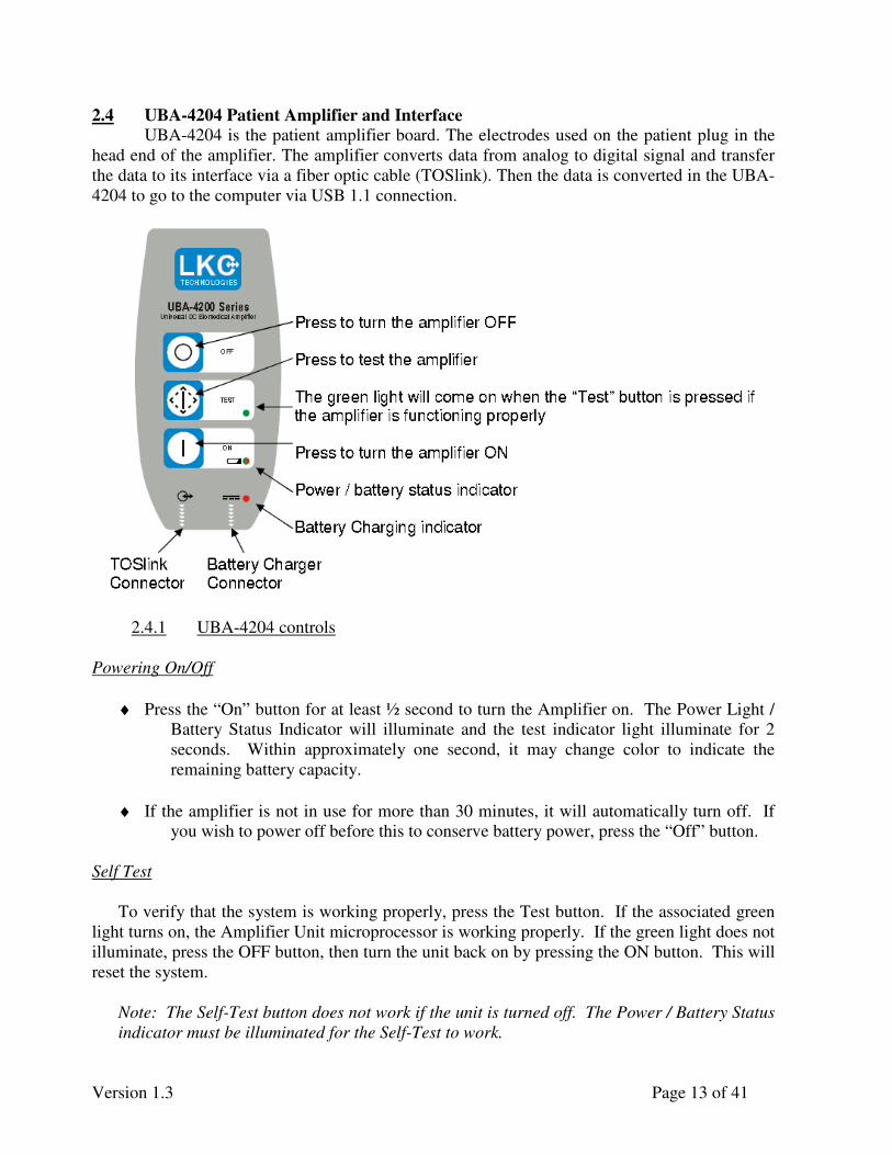
2.4 UBA-4204 Patient Amplifier and Interface
UBA-4204 is the patient amplifier board. The electrodes used on the patient plug in the
head end of the amplifier. The amplifier converts data from analog to digital signal and transfer
the data to its interface via a fiber optic cable (TOSlink). Then the data is converted in the UBA-
4204 to go to the computer via USB 1.1 connection.
2.4.1 UBA-4204 controls
Powering On/Off
♦ Press the “On” button for at least ½ second to turn the Amplifier on. The Power Light /
Battery Status Indicator will illuminate and the test indicator light illuminate for 2
seconds. Within approximately one second, it may change color to indicate the
remaining battery capacity.
♦ If the amplifier is not in use for more than 30 minutes, it will automatically turn off. If
you wish to power off before this to conserve battery power, press the “Off” button.
Self Test
To verify that the system is working properly, press the Test button. If the associated green
light turns on, the Amplifier Unit microprocessor is working properly. If the green light does not
illuminate, press the OFF button, then turn the unit back on by pressing the ON button. This will
reset the system.
Note: The Self-Test button does not work if the unit is turned off. The Power / Battery Status
indicator must be illuminated for the Self-Test to work.

Version 1.3 Page 14 of 41
2.4.2 UBA-4204 Inputs
UBA-4204 has 1.5 mm male DIN safety connectors (which accommodate connections to
most electrodes). The channel connections are indicated on the back label of the Amplifier Unit.
It has 4 differential inputs and a ground.
UBA-4204 Inputs (back label)
2.4.3 Battery Charging
The UBA-4204 Amplifier Unit is powered by an internal rechargeable Lithium-ion
battery. A fully charged battery will allow you to collect data continuously for up to 12 hours.
The required time to recharge a fully depleted battery is 8 hours, with ~80% of the charge
restored within the first 4 hours.
If the battery is fully depleted (unit will not turn on), recharging the battery for 10
minutes should provide enough charge to operate the unit for approximately ½ hour.
The battery charge indicator is the LED next to the Battery Check symbol on the front of the
UBA-4204; it indicates the remaining amount of battery charge.
Battery Check Symbol
LEDs Illuminated Remaining Battery
Charge
Green > 30 %
Green + Red 10 % - 30 %
Red < 10 %
Do not charge the battery while the UBA-4204 Amplifier Unit is connected to a
patient.
1234
C +
Model UBA-4204(PATENT PENDING)
Serial Number
LKC Technologies, Inc. 2 Professional Drive, Suite 222 Gaithersburg, MD 20879 USA Phone: 301.840.1992 Fax: 301.330.2237 [email protected] www.LKC.com

Version 1.3 Page 15 of 41
To charge the battery, insert the Battery Charger Power Supply connector into the Amplifier Unit
directly below the DC Power symbol and plug the power cord into a wall outlet or isolation
transformer. The Battery Charger Power Supply can be used with inputs from 100-240V 50/60
Hz.
DC Power Symbol
2.4.4 Changing The Battery
The battery is designed to withstand approximately 5,000 discharge cycles. As you
approach this number, the operating time per recharge will decline. If you need a battery
replacement you have will have to return the amplifier unit to LKC Technologies where trained
personnel will install a replacement battery. (Battery replacement is not covered under
warranty.) Please contact LKC Technologies Customer Support before returning your amplifier
for this service.
Use only a genuine replacement battery from LKC Technologies. Use of other
batteries may be hazardous.
Version 1.3 Page 16 of 41
2.5 Ganzfeld
The Full-Field Ganzfeld Stimulator is connected to the system interface unit and controlled by
the system’s computer. The UTAS system can come with either a Sunburst Ganzfeld or a
BigShot ganzfeld.
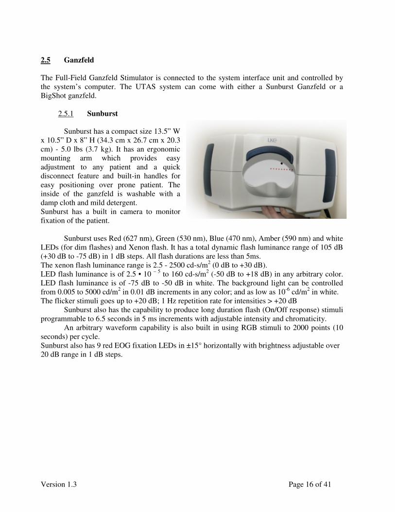
2.5.1 Sunburst
Sunburst has a compact size 13.5” W
x 10.5” D x 8” H (34.3 cm x 26.7 cm x 20.3
cm) - 5.0 lbs (3.7 kg). It has an ergonomic
mounting arm which provides easy
adjustment to any patient and a quick
disconnect feature and built-in handles for
easy positioning over prone patient. The
inside of the ganzfeld is washable with a
damp cloth and mild detergent.
Sunburst has a built in camera to monitor
fixation of the patient.
Sunburst uses Red (627 nm), Green (530 nm), Blue (470 nm), Amber (590 nm) and white
LEDs (for dim flashes) and Xenon flash. It has a total dynamic flash luminance range of 105 dB
(+30 dB to -75 dB) in 1 dB steps. All flash durations are less than 5ms.
The xenon flash luminance range is 2.5 - 2500 cd-s/m2 (0 dB to +30 dB).
LED flash luminance is of 2.5 • 10 – 5
to 160 cd-s/m2 (-50 dB to +18 dB) in any arbitrary color.
LED flash luminance is of -75 dB to -50 dB in white. The background light can be controlled
from 0.005 to 5000 cd/m2 in 0.01 dB increments in any color; and as low as 10
-6 cd/m
2 in white.
The flicker stimuli goes up to +20 dB; 1 Hz repetition rate for intensities > +20 dB
Sunburst also has the capability to produce long duration flash (On/Off response) stimuli
programmable to 6.5 seconds in 5 ms increments with adjustable intensity and chromaticity.
An arbitrary waveform capability is also built in using RGB stimuli to 2000 points (10
seconds) per cycle.
Sunburst also has 9 red EOG fixation LEDs in ±15° horizontally with brightness adjustable over
20 dB range in 1 dB steps.
Version 1.3 Page 17 of 41
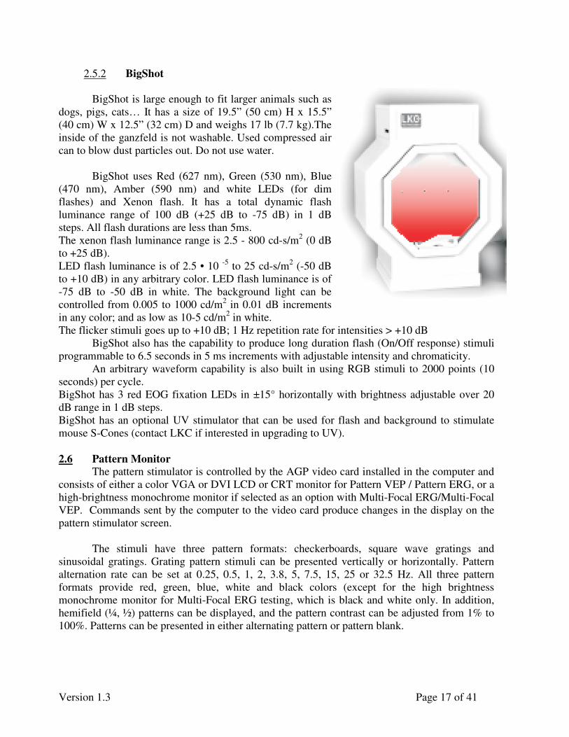
2.5.2 BigShot
BigShot is large enough to fit larger animals such as
dogs, pigs, cats… It has a size of 19.5” (50 cm) H x 15.5”
(40 cm) W x 12.5” (32 cm) D and weighs 17 lb (7.7 kg).The
inside of the ganzfeld is not washable. Used compressed air
can to blow dust particles out. Do not use water.
BigShot uses Red (627 nm), Green (530 nm), Blue
(470 nm), Amber (590 nm) and white LEDs (for dim
flashes) and Xenon flash. It has a total dynamic flash
luminance range of 100 dB (+25 dB to -75 dB) in 1 dB
steps. All flash durations are less than 5ms.
The xenon flash luminance range is 2.5 - 800 cd-s/m2 (0 dB
to +25 dB).
LED flash luminance is of 2.5 • 10 -5
to 25 cd-s/m2 (-50 dB
to +10 dB) in any arbitrary color. LED flash luminance is of
-75 dB to -50 dB in white. The background light can be
controlled from 0.005 to 1000 cd/m2 in 0.01 dB increments
in any color; and as low as 10-5 cd/m2 in white.
The flicker stimuli goes up to +10 dB; 1 Hz repetition rate for intensities > +10 dB
BigShot also has the capability to produce long duration flash (On/Off response) stimuli
programmable to 6.5 seconds in 5 ms increments with adjustable intensity and chromaticity.
An arbitrary waveform capability is also built in using RGB stimuli to 2000 points (10
seconds) per cycle.
BigShot has 3 red EOG fixation LEDs in ±15° horizontally with brightness adjustable over 20
dB range in 1 dB steps.
BigShot has an optional UV stimulator that can be used for flash and background to stimulate
mouse S-Cones (contact LKC if interested in upgrading to UV).
2.6 Pattern Monitor
The pattern stimulator is controlled by the AGP video card installed in the computer and
consists of either a color VGA or DVI LCD or CRT monitor for Pattern VEP / Pattern ERG, or a
high-brightness monochrome monitor if selected as an option with Multi-Focal ERG/Multi-Focal
VEP. Commands sent by the computer to the video card produce changes in the display on the
pattern stimulator screen.
The stimuli have three pattern formats: checkerboards, square wave gratings and
sinusoidal gratings. Grating pattern stimuli can be presented vertically or horizontally. Pattern
alternation rate can be set at 0.25, 0.5, 1, 2, 3.8, 5, 7.5, 15, 25 or 32.5 Hz. All three pattern
formats provide red, green, blue, white and black colors (except for the high brightness
monochrome monitor for Multi-Focal ERG testing, which is black and white only. In addition,
hemifield (¼, ½) patterns can be displayed, and the pattern contrast can be adjusted from 1% to
100%. Patterns can be presented in either alternating pattern or pattern blank.

Version 1.3 Page 18 of 41
2.7 CMGS-1 Color Mini-Ganzfeld Stimulator (optional)
The optional CMGS-1 Color Mini-Ganzfeld Stimulator consists of two units: the control
box and hand-held mini-Ganzfeld. The CMGS-1 is controlled by the system computer via a
serial port connection.
Various color LEDs are used to produce red, green, blue, or white stimuli. The intensity
of white flash/flicker can be set to the following levels: +10 dB, +5 dB, 0, -5, -10, -15, -20 or -25
dB, while color R/G/B stimuli can reach a maximum intensity of +2 dB. The background
intensity can be set to any of three levels for the white, red, green and blue colors. The CMGS-1
also provides On/Off Response stimuli with W/R/G/B color. A dim red LED is mounted at the
back of the mini-Ganzfeld for fixation.
2.8 MGS-2 White-Only Mini-Ganzfeld (optional)
The optional MGS-2 Mini-Ganzfeld consists of two units: the control box and hand-held
mini-Ganzfeld. The MGS-2 is controlled by the system computer via a serial port connection.
A number of bright white LEDs are used to produce the stimulus. The intensity of the
stimulus can be set to +5dB, 0, -5, -10, -15, -20 or -25 dB level. The brightness of the
background light is fixed to 30cd/m² for flash and flicker stimuli. A dim red LED is mounted at
the back of the mini-Ganzfeld for fixation.
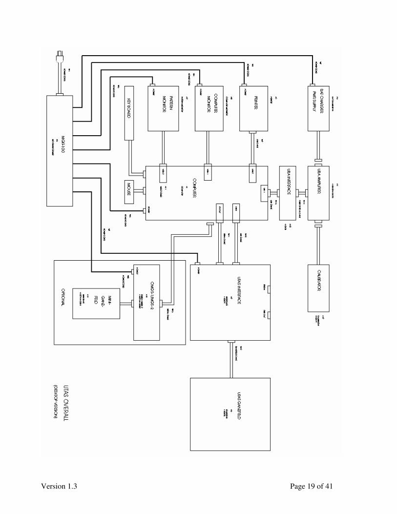
2.9 Overall Equipment Interrelations
Figures 1 and 2 below are the block diagrams of the system in the two versions, showing how
the various elements of an UTAS system are interconnected.
The functional paths are:
• Signal
• Control
• Display
Signals travel from the patient to the amplifier unit where the signals are converted from Analog
to Digital and passed on to UBA-4204 interface. In UBA-4204 the data is then converted to be
sent to the computer via USB 1.1 connection to the computer. The computer collects signals for
digital amplification and filtering, averaging, computing, display, and analysis.
The user utilizes the mouse and keyboard of the computer and the computer controls the pattern
monitor stimulator, Ganzfeld or Mini-Ganzfeld and amplifier unit.
There are three displays in the system: the computer operator display, the pattern monitor
stimulator display and the printer. The operator display is controlled by the added video card; the
pattern monitor is controlled by the video board that is already on the computer motherboard.
The printer is connected via USB connection.
Version 1.3 Page 19 of 41

Version 1.3 Page 20 of 41
Version 1.3 Page 21 of 41
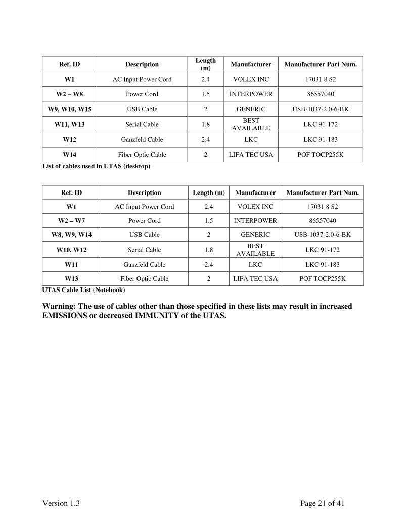
Ref. ID Description Length
(m) Manufacturer Manufacturer Part Num.
W1 AC Input Power Cord 2.4 VOLEX INC 17031 8 S2
W2 – W8 Power Cord 1.5 INTERPOWER 86557040
W9, W10, W15 USB Cable 2 GENERIC USB-1037-2.0-6-BK
W11, W13 Serial Cable 1.8 BEST
AVAILABLE LKC 91-172
W12 Ganzfeld Cable 2.4 LKC LKC 91-183
W14 Fiber Optic Cable 2 LIFA TEC USA POF TOCP255K
List of cables used in UTAS (desktop)
Ref. ID Description Length (m) Manufacturer Manufacturer Part Num.
W1 AC Input Power Cord 2.4 VOLEX INC 17031 8 S2
W2 – W7 Power Cord 1.5 INTERPOWER 86557040
W8, W9, W14 USB Cable 2 GENERIC USB-1037-2.0-6-BK
W10, W12 Serial Cable 1.8 BEST
AVAILABLE LKC 91-172
W11 Ganzfeld Cable 2.4 LKC LKC 91-183
W13 Fiber Optic Cable 2 LIFA TEC USA POF TOCP255K
UTAS Cable List (Notebook)
Warning: The use of cables other than those specified in these lists may result in increased
EMISSIONS or decreased IMMUNITY of the UTAS.
Version 1.3 Page 22 of 41
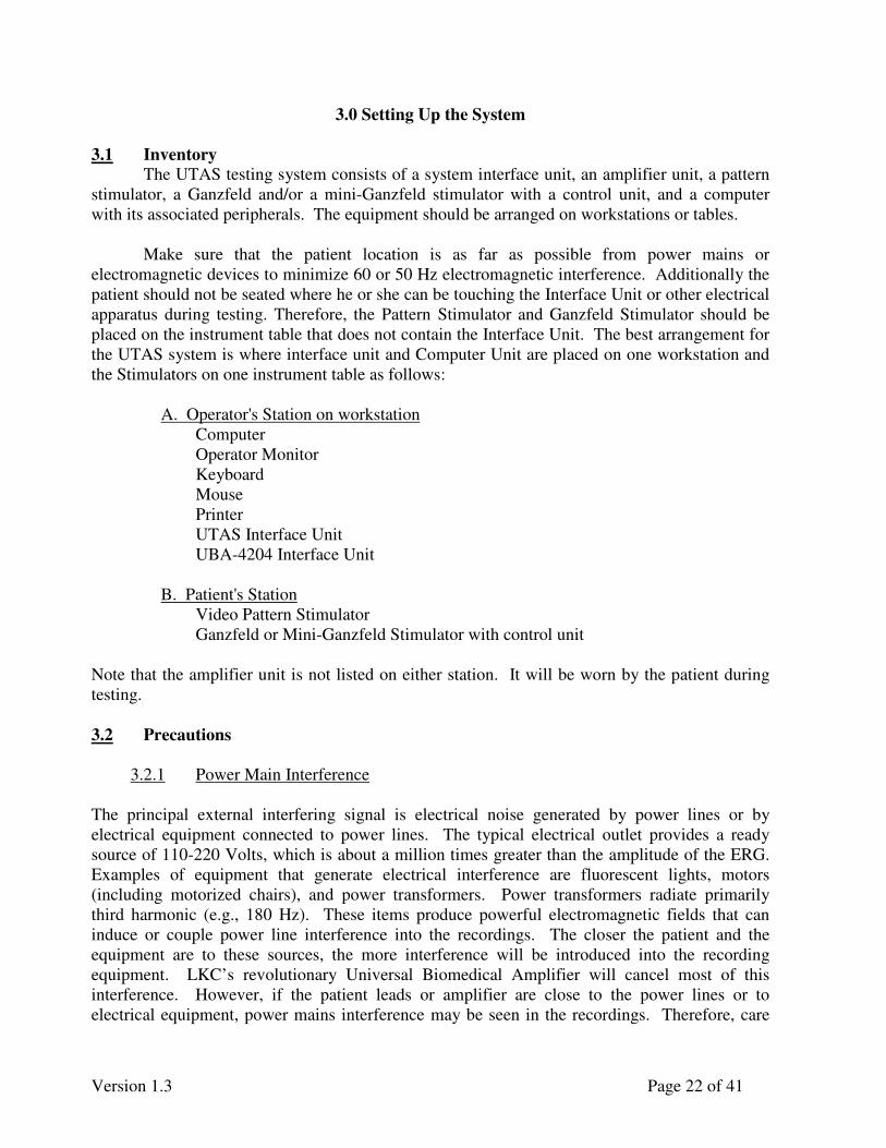
3.0 Setting Up the System
3.1 Inventory
The UTAS testing system consists of a system interface unit, an amplifier unit, a pattern
stimulator, a Ganzfeld and/or a mini-Ganzfeld stimulator with a control unit, and a computer
with its associated peripherals. The equipment should be arranged on workstations or tables.
Make sure that the patient location is as far as possible from power mains or
electromagnetic devices to minimize 60 or 50 Hz electromagnetic interference. Additionally the
patient should not be seated where he or she can be touching the Interface Unit or other electrical
apparatus during testing. Therefore, the Pattern Stimulator and Ganzfeld Stimulator should be
placed on the instrument table that does not contain the Interface Unit. The best arrangement for
the UTAS system is where interface unit and Computer Unit are placed on one workstation and
the Stimulators on one instrument table as follows:
A. Operator's Station on workstation
Computer
Operator Monitor
Keyboard
Mouse
Printer
UTAS Interface Unit
UBA-4204 Interface Unit
B. Patient's Station
Video Pattern Stimulator
Ganzfeld or Mini-Ganzfeld Stimulator with control unit
Note that the amplifier unit is not listed on either station. It will be worn by the patient during
testing.
3.2 Precautions
3.2.1 Power Main Interference
The principal external interfering signal is electrical noise generated by power lines or by
electrical equipment connected to power lines. The typical electrical outlet provides a ready
source of 110-220 Volts, which is about a million times greater than the amplitude of the ERG.
Examples of equipment that generate electrical interference are fluorescent lights, motors
(including motorized chairs), and power transformers. Power transformers radiate primarily
third harmonic (e.g., 180 Hz). These items produce powerful electromagnetic fields that can
induce or couple power line interference into the recordings. The closer the patient and the
equipment are to these sources, the more interference will be introduced into the recording
equipment. LKC’s revolutionary Universal Biomedical Amplifier will cancel most of this
interference. However, if the patient leads or amplifier are close to the power lines or to
electrical equipment, power mains interference may be seen in the recordings. Therefore, care

Version 1.3 Page 23 of 41
should be taken to locate the testing equipment and subject away from any major source of
electrical interference.
3.2.2 High Frequency Electrical Noise
Beyond the power lines or equipment such as motors and transformers, electrical noise
can be produced by equipment generating noise at radio frequencies. Although one might expect
such signals to be filtered out by the amplifier filters, it is possible for this type of noise to
generate low frequency artifacts by nonlinearities in the recording equipment and by mixing with
other signals. Therefore, care should be exercised to keep the recording equipment and subject
away from strong sources of radio frequency interference.
Noisy signals can also be coming from near by MRI systems; this will create noise and/or
unrecordable data.
3.2.3 Shielding
If you cannot find a location which is free of interfering apparatus, it is possible to create
simple shielding which will usually control the interference. The shielding material can be
copper or aluminum screening material which can be placed below the patient and covered with
an anti-static mat or placed around interfering apparatus. The screen and mat, if used, should be
securely connected to electrical ground.
3.3 Equipment Interconnections
The equipment is interconnected as shown in Figure 1 for a desktop version of the UTAS
system and Figure 2 for a laptop version system. Make certain that the power is off before
making any connections. All of the equipment in your UTAS must be connected for the system
to function properly.
Computer to Operator’s Monitor. Your desktop version system comes with connections for
two monitors. They will be labeled User’s Monitor, Pattern Monitor. Plug the operator’s
monitor into the connection labeled User’s Monitor. Computer to Pattern Stimulator. Plug the pattern monitor into the connection labeled Pattern
Monitor.
Computer to Printer. Plug the printer into any USB connector on computer rear panel using a
standard USB cable.
Computer to Keyboard. A cable connects the keyboard to the computer. The keyboard end is
permanently attached; the computer end is a plug that connects to a receptacle, or to one of the
USB connectors on the back of the computer.
Computer to Mouse. A flexible cable connects the mouse to the computer. The mouse end is
permanently attached; the computer end is a plug that connects to a receptacle, or to one of the
USB connectors on the back of the computer.

Version 1.3 Page 24 of 41
Computer to UTAS System Interface Unit. A serial port extension cable connects the
computer to the UTAS system interface unit. The female end goes to the 9-pin RS232 connector
on the back of the computer, and the male end goes to the interface rear panel. A USB cable
connects into the back of the interface unit. The other end connects to any available USB port on
the computer.
UBA-4204 to UBA-4204 Interface Unit. Connect using a fiber optic cable (TOSlink). The two
ends are interchangeable.
UBA-4204 Interface Unit to Computer. Connects via USB 1.1 cable to the back of the
computer.
WARNING: The USB cable should be in the USB port that was labeled for it
before shipping. If the USB cable is plugged in another USB port the computer won’t recognize the device.
System Interface Unit Ganzfeld (Sunburst or BigShot). An 8 Foot, fiberglass-sleeved cable
connects the ganzfeld’s interface to ganzfeld. The 16-pin plastic connector on the cable goes to
the back panel of the system interface unit.
Computer to CMGS-1/MGS-2 Control Unit (optional). In the case you bought a CMGS-1 or
MGS-2 with your system then a splitting serial cable will be furnished. The female end goes to
the 9-pin RS232 connector on the back of the computer, on of the two male end goes to the
interface rear panel, the other goes to the CMGS-1 or MGS-2.
CMGS-1/MGS-2 Control Unit to Color/White Mini-Ganzfeld (optional) The Control box
end of the mini-Ganzfeld cable has a 25-pin connector, which connects to the rear panel of the
box, and the other end is permanently attached to the hand-held mini-Ganzfeld head.
Power Connections. The equipment requiring connections to A.C. power of the MGIT are the
following:
• Computer
• Computer Monitor or AC/DC Adaptor if LCD Monitor is used and DC powered
• Printer or AC/DC Adaptor for Printer
• Pattern Stimulator Monitor
• System Interface Unit
• Battery Charger for Patient Amplifier (UBA-4204)
• CMGS-1/MGS-2 Control Unit (optional accessory)
Version 1.3 Page 25 of 41
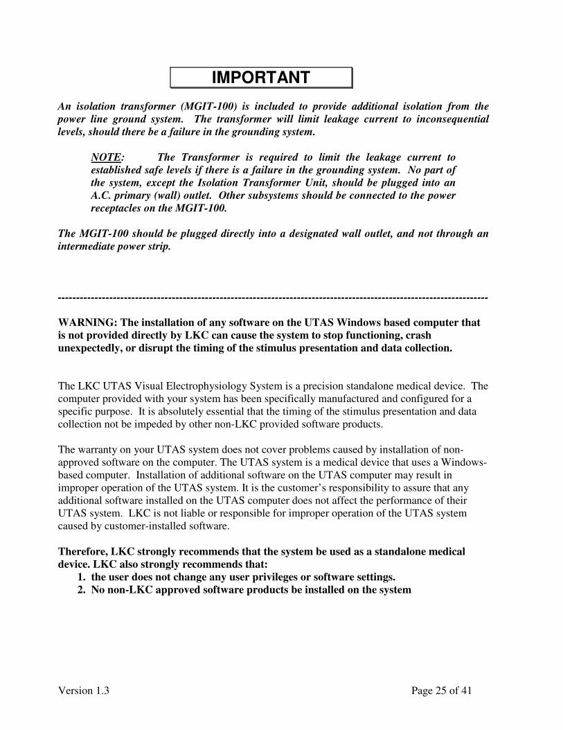
An isolation transformer (MGIT-100) is included to provide additional isolation from the
power line ground system. The transformer will limit leakage current to inconsequential
levels, should there be a failure in the grounding system.
NOTE: The Transformer is required to limit the leakage current to
established safe levels if there is a failure in the grounding system. No part of
the system, except the Isolation Transformer Unit, should be plugged into an
A.C. primary (wall) outlet. Other subsystems should be connected to the power
receptacles on the MGIT-100.
The MGIT-100 should be plugged directly into a designated wall outlet, and not through an
intermediate power strip.
---------------------------------------------------------------------------------------------------------------------
WARNING: The installation of any software on the UTAS Windows based computer that
is not provided directly by LKC can cause the system to stop functioning, crash
unexpectedly, or disrupt the timing of the stimulus presentation and data collection.
The LKC UTAS Visual Electrophysiology System is a precision standalone medical device. The
computer provided with your system has been specifically manufactured and configured for a
specific purpose. It is absolutely essential that the timing of the stimulus presentation and data
collection not be impeded by other non-LKC provided software products.
The warranty on your UTAS system does not cover problems caused by installation of non-
approved software on the computer. The UTAS system is a medical device that uses a Windows-
based computer. Installation of additional software on the UTAS computer may result in
improper operation of the UTAS system. It is the customer’s responsibility to assure that any
additional software installed on the UTAS computer does not affect the performance of their
UTAS system. LKC is not liable or responsible for improper operation of the UTAS system
caused by customer-installed software.
Therefore, LKC strongly recommends that the system be used as a standalone medical
device. LKC also strongly recommends that:
1. the user does not change any user privileges or software settings.
2. No non-LKC approved software products be installed on the system
IMPORTANT
Version 1.3 Page 26 of 41
4.0 Before You Use the System
Your UTAS system comes with a PC that contains a hard disk drive. All of the
UTAS software has been installed on the hard disk for you, and your recordings will be stored on
the hard drive as well. Unfortunately, hard disk drives sometimes fail, and when they do, there
may be no way to recover the lost information. For this reason, you should backup all important
information on disks.
In addition to the UTAS software on hard disk, the software program, EMWin (as
well as SVEP and/or MFERG/MFVEP if applicable) is supplied on one CD-ROM. This is a
backup copy in the event that the program on your hard disk becomes corrupted. As a
precaution, you may want to make an additional backup copy of this disk. You can accomplish
this using the rewriteable CD-ROM drive on the system computer.
Keep the copy near your UTAS system, and store the original in a safe place
(preferably in another location).

Version 1.3 Page 27 of 41
5.0 Checking UBA-4204 (Amplifier) Response
Using the balck plastic Verif Eye box that was shipped with your system, you can check if your
UBA-4204 is working fine.
♦ Plug the box’s red wire in channel 1+, black wire in channel 1-
♦ Turn switch on the box up for ON
♦ Place the box in the ganzfeld gently to avoid scratching the paint
♦ Turn UBA-4204 ON
♦ Start EMWIN -> Perform Test -> ERG -> Standard ERG
♦ Go to step 2 (0dB scotopic flash)
♦ In Sunburst Parameters TURN THE IR LED OFF (Skip this step for BigShot as it
doesn’t have IR LEDs)
♦ Click on Baseline and Record – Stop Baseline and then Record
♦ Once done with the test remember to TURN THE IR LED back ON
♦ Turn switch OFF
The ganzfeld will deliver a 0dB flash that will trigger the photo sensor of the pulse box and
should show as a 150 µV pulse of 20ms width. See picture below. The IR LEDs are
automatically turned on as you power the system up. They are used in conjunction with the mini
webcam to see the eyes of the patients in dark while recording. However the IR LEDs saturate
the photo sensor of the check box. Hence they need to be turned off during the time you are
looking for the pulse.
Version 1.3 Page 28 of 41
6.0 Checking Ganzfeld Calibration (for Sunburst and BigShot)
6.1 Overview
The UTAS with Sunburst comes with a calibration checking application. Original
calibration values are stored in the memory of the system. The calibration check software allows
the user to check new calibration measurement and compare it to the original factory calibration
data. Note that there is no way for the user to calibrate any of the light sources; the unit needs to
be returned to the factory if recalibration is needed. Also note that this application is NOT
available for BigShot
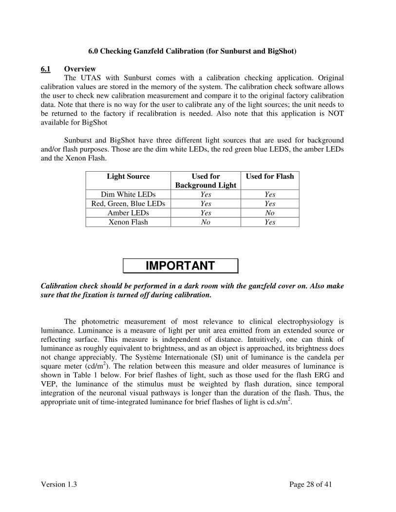
Sunburst and BigShot have three different light sources that are used for background
and/or flash purposes. Those are the dim white LEDs, the red green blue LEDS, the amber LEDs
and the Xenon Flash.
Light Source Used for
Background Light
Used for Flash
Dim White LEDs Yes Yes
Red, Green, Blue LEDs Yes Yes
Amber LEDs Yes No
Xenon Flash No Yes
Calibration check should be performed in a dark room with the ganzfeld cover on. Also make
sure that the fixation is turned off during calibration.
The photometric measurement of most relevance to clinical electrophysiology is
luminance. Luminance is a measure of light per unit area emitted from an extended source or
reflecting surface. This measure is independent of distance. Intuitively, one can think of
luminance as roughly equivalent to brightness, and as an object is approached, its brightness does
not change appreciably. The Système Internationale (SI) unit of luminance is the candela per
square meter (cd/m2). The relation between this measure and older measures of luminance is
shown in Table 1 below. For brief flashes of light, such as those used for the flash ERG and
VEP, the luminance of the stimulus must be weighted by flash duration, since temporal
integration of the neuronal visual pathways is longer than the duration of the flash. Thus, the
appropriate unit of time-integrated luminance for brief flashes of light is cd.s/m2.
IMPORTANT
Version 1.3 Page 29 of 41
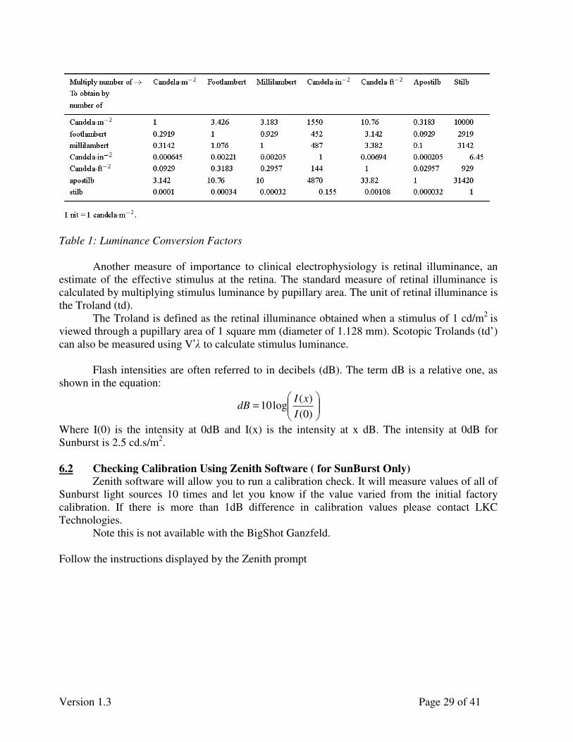
Table 1: Luminance Conversion Factors
Another measure of importance to clinical electrophysiology is retinal illuminance, an
estimate of the effective stimulus at the retina. The standard measure of retinal illuminance is
calculated by multiplying stimulus luminance by pupillary area. The unit of retinal illuminance is
the Troland (td).
The Troland is defined as the retinal illuminance obtained when a stimulus of 1 cd/m2
is
viewed through a pupillary area of 1 square mm (diameter of 1.128 mm). Scotopic Trolands (td’)
can also be measured using V’λ to calculate stimulus luminance.
Flash intensities are often referred to in decibels (dB). The term dB is a relative one, as
shown in the equation:
=
)0(
)(log10
I
xIdB
Where I(0) is the intensity at 0dB and I(x) is the intensity at x dB. The intensity at 0dB for
Sunburst is 2.5 cd.s/m2.
6.2 Checking Calibration Using Zenith Software ( for SunBurst Only)
Zenith software will allow you to run a calibration check. It will measure values of all of
Sunburst light sources 10 times and let you know if the value varied from the initial factory
calibration. If there is more than 1dB difference in calibration values please contact LKC
Technologies.
Note this is not available with the BigShot Ganzfeld.
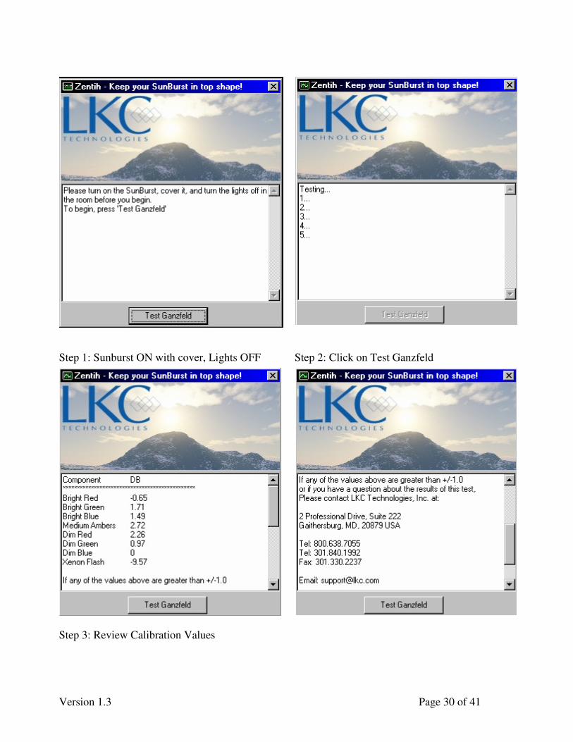
Follow the instructions displayed by the Zenith prompt
Version 1.3 Page 30 of 41
Step 1: Sunburst ON with cover, Lights OFF Step 2: Click on Test Ganzfeld
Step 3: Review Calibration Values

Version 1.3 Page 31 of 41
6.3 Checking Calibration On Your Own
In order to check calibration on your own you will need:
♦ A Model 2550 Digital Radiometer/Photometer for calibrating the dim white flashes as
well as the Xenon flashes. Other photometers are acceptable for calibration if they
measure light intensity in either candelas per square meter (cd/m2) or in foot-Lambert
(fL). The photometer must also be capable of integrating its response to measure
candela-seconds per square meter (cd.s/m2) or foot –Lambert-seconds (fL-s).
Conversion: Lftm
cd−= 1426.3
2
♦ A CS-100 Minolta Chroma Meter to check calibration of the Red, Green and Blue
LED flashes and background (0-5000 cd/m2) and the Amber background.
6.3.1 Checking Calibration of Dim White LED
In order to check calibration for the dim white flashes the DR-2550 should be used in
integrating mode. The dim white LEDs have such low luminance that they have to be integrated
over a large amount of time.
♦ Place the photometer probe pointed at the back of the ganzfeld and set it on integrating
mode
♦ Set background light to -50dB
♦ Turn off the lights and cover ganzfeld with its cover.
♦ Measure background light
6.3.2 Checking Calibration of Xenon Flash
In order to check calibration for the dim white flashes the DR-2550 should be used in
integrating mode.
♦ Place the photometer probe pointed at the back of the ganzfeld and set it on integrating
mode
♦ Turn off the lights and cover the ganzfeld with its cover.
♦ Fire the Xenon flash at 10dB and measure in fL-s
6.3.3 Checking Calibration of Color LEDs
In order to check calibration for the color LEDs the CS-100 Chroma Meter is needed.
Colors green, red and blue LEDs are used for background light and flash. It is fair to assume that
is the calibration of intensity and color coordinate is correct for background; it will be also be
correct for flashes.
♦ Set the background light of ganzfeld to the coordinate you wish to measure (intensity and
x, y coordinate for color)
♦ Turn lights off
♦ Place the Chroma Meter inside of ganzfeld make sure the image is in focus and set it on
cd/m2
♦ Read off measurement and compare to the intensity and color coordinate you chose.
6.4 Replacing Background or Flash Lamps/LEDs
LEDs and Xenon tubes can only be changed in factory at LKC Technologies, Inc. Please
contact the LKC support line to get information on how to send your system.

Service Manual
Version 1.3 Page 32 of 41
7.0 External Triggers (Input and Output)
The rear of the LKC Interface Unit contains two BNC connectors labeled Trigger In and
Trigger Out. These connectors allow you to connect external stimulators to your UTAS system.
This appendix will provide you with some of the information necessary to connect external
stimulator to your UTAS system.
Trigger In and Trigger Out are default to negative going TTL unless specified otherwise
at time of purchase. Contact LKC for information on how to change trigger polarity.
7.1 Triggering External Equipment – Trigger Out
The BNC connector marked Trigger Out on the back of the Interface can be used to
trigger an external piece of equipment. The trigger signal is a negative going TTL compatible
output of approximately 1 ms duration.
Note that the trigger should be providing the voltage through a 1k resistor to the UTAS
Interface.
A signal appears at the Trigger Out BNC whenever Sunburst or BigShot produces a
flash. In case of an ON/OFF response the trigger will go low at the start of the stimulus and will
go high again once the stimulus is over.
7.2 Receiving Triggers from External Equipment – Trigger In
If you have a stimulator that can provide a trigger signal to the UTAS Interface, you may
record data using your own stimulator. The BNC connector marked Trigger Out on the back of
the interface can be used to receive triggers from an external piece of equipment.
Please contact LKC Technologies, Inc. before connecting any external
equipment to the Trigger In or Out connector of the Interface Unit.
Warning If the stimulators are not connected properly to the Interface Unit,
damage may result to either the Interface Unit or to your stimulator. If you have
any doubts, please contact LKC before proceeding.
Service Manual
Version 1.3 Page 33 of 41
8.0 Cleaning The System Between Patients
8.1 Cleaning Reusable Burian-Allen Contact Lens Electrodes
Clean the electrode with a 50/50 mixture of liquid Tide detergent (or any mild detergent) and
distilled water (note that letting tears dry on the lens after testing makes them very difficult to
remove!). The water you soak them in should not be acidic (i.e. “hard” water), as it will cause
the electrolysis between the solder (tin/zinc), which will turn the silver black. If left over a
weekend it will fall apart and have to be reconditioned. The electrode may then be rinsed off
with tap water. Rinsing will not cause electrolysis, as soaking for extended periods of time in
hard water will.
After cleaning the Burian-Allen electrode, it can be disinfected with 1:10 bleach method for
5 minutes (no longer). Using the same soapy water mixture, the silver on the electrode can be
scrubbed lightly with a toothbrush (only the silver, make sure not to scrub the wire spring). This
should be followed by a thorough rinse. Note that the electrode should not be exposed to the
bleach for more than 5 minutes (longer can cause the silver to turn brown), and the concentration
of the bleach should be 0.5%, not 5% (straight Clorox is 5.25%). Also note that some
deterioration of the electrode will occur over time, even when this method is used properly.
The Burian-Allen electrode can also be disinfected with activated dialdehyde
(Glutaraldehyde), sold under the trade names Cidex, CabcoCide and Sporcide. All of these will
have usage instructions on the containers, which should be followed. Note that we have soaked
the electrode in activated dialdehyde for over 4 days and noticed no visible effects.
A third method of disinfecting is to use Ethylene Oxide at 125 degrees Fahrenheit. The heat
will not harm the electrode.
To check the electrode for damage you should check the ring, the speculum inner edge, the
speculum outer edge, the speculum surface, and the lens edge (for chips). If the electrode is
damaged and needs repair, please contact LKC.
Note: ERG-Jets and DTL electrodes are disposable. This cleaning method does NOT apply to
them.
8.2 Cleaning the Forehead Rest
The patient’s forehead will come into contact with the ganzfeld forehead rest during
testing. The forehead rest should be cleaned and disinfected between uses to prevent the spread
of skin infections.
The simplest method of cleaning and disinfecting the forehead rest is to wipe it down
with a 70% isopropyl alcohol solution. Using a disinfecting wipe is a good way to do this. You

Service Manual
Version 1.3 Page 34 of 41
may also clean the forehead rest using a glutaraldehyde solution, such as those mentioned in
Section 8.1.
9.0 Troubleshooting Guide
This section lists the most frequently encountered problems along with typical solutions.
8.1 Computer Boot-up The computer does not boot up or properly
1) Bad power supply.
2) Computer battery discharged.
4) Windows operating system file(s) damaged.
5) Hard disk power cable loose.
WARNING: Tighten or hook up cables with system power OFF. Cables
hooked up backwards will permanently damage the hard disk.
6) If none of the above seems to be the problem, then the hard disk controller may be
defective.
8.2 Computer Monitor No display on the computer monitor
1) Power is off
2) Video cable is loose
3) Power cable to monitor is loose
4) Video board is bad
5) A bad monitor
Wrong color display or reverse video display
1) Loose video cable
2) Bad video card
3) Bad monitor
4) Wrong display setting
8.3 Keyboard No keyboard acknowledgment or keyboard error
1) Keyboard not connected to the computer
2) Bad keyboard
3) Key being pressed or stuck at the time of boot-up
4) Dirty contacts inside keyboard
8.4 Mouse Mouse error message at the time of boot-up
1) Mouse not connected to the connector on the computer
2) Mouse bad

Service Manual
Version 1.3 Page 35 of 41
Mouse screen cursor not moving without boot-up error message as described above
1) No mouse software driver installed
2) Two different and conflicting versions of the software mouse drivers installed
8.6 Printer Printer Does Not Print or Prints Garbage
1) Printer is not powered on
2) Printer out of paper
3) Disconnected printer cable at either computer or printer end
4) Wrong printer type selected in software
5) Printer driver not install
6) Ink of Cartridge low or dried out
8.7 Ganzfeld No flash/LED/background Light stimulators functioning. (No Ganzfeld function)
1) Loose or disconnected RS-232 cable from computer to interface unit
2) Bad serial port in computer
3) Loose connector to the interface serial port control board
4) Bad interface serial port control board
5) Ganzfeld cable not connected or not tight enough
6) Bad power supply in interface unit
8.8 Data Waveforms are perfectly flat for all channels even with patient cable leads left open
1) Amplifier unit is off. Press ON button and verify that the power LED is lit.
2) Interface unit is off make sure it is plugged in the computer
3) USB cable is unplugged from computer or interface
4) TOSlink cable is unplugged from either amplifier or interface
5) TOSlink cable is broken
6) Bad USB port
7) USB plugged in wrong USB port
8) USB port needs to be reset – remove the USB connector from the UBA-4204 interface
and plug it back in
9) USB port has been changed from its manufacturing position, please plug interface where
the label “UBA” is on ganzfeld.
8.9 Mini-ganzfeld Mini-ganzfeld does not function (no flash, no fixation and no background light)
1) Mini-ganzfeld not selected in system setup
2) Standard with Kurbisfeld or Flicker with Kurbisfeld protocol not selected
3) Bad serial port in computer
4) Loose or disconnected RS-232 cable from computer to interface unit
5) Loose connector to the serial port control board inside the control box
6) Loose connector to the control board inside the control box
7) Bad mini-ganzfeld control board in the control box

Service Manual
Version 1.3 Page 36 of 41
8) Bad serial port control board in the control box
9) Bad power supply in control box
8.10 Interference Excessive interference appearing on recordings
1) See Section 3.1 for setup precautions.
2) Be sure that good electrode contact has been achieved
a. Care should be taken to thoroughly clean the site of the electrode placement with
skin cleaner.
b. All electrode cups should be filled with an adequate amount of electrode gel or
cream.
c. In ERG recording, adding an extra drop of artificial tears to the contact lens
electrode while it is in the patient's eye may reduce the electrode impedance.
d. Check that recording connections are as recommended in the Operations manual
In addition, electrode leads should be as short as possible and kept away from any
electrical equipment or power lines, MRI machines. It often helps to twist the positive and
negative electrode leads to cancel signals caused by magnetic induction. About one twist per
inch should be adequate. With these precautions, electrical noise due to radio frequency
equipment will ordinarily be within acceptable limits.
3) After all steps to minimize noise have been taken and interference is still present in the
recording signal, the Notch filter can be used. The Notch filter is a very narrow bandwidth filter
centered at 60(50) Hertz which will reduce power line noise. There will, however, be some loss
of waveform information since part of the waveform spectrum is affected. To check if the Notch
filter is working properly, unplug the calibration box, change the amplifier setting to 30 Hz for
low cut, and 70 Hz for high cut, and get a baseline. Then place the Notch filter ON and try to get
a baseline again. Measure how much the peak to peak amplitude of the interference has been
reduced, if the ratio is about ten, then the Notch filter is working properly.

Appendix 1
Version 1.3 Page 37 of 41
Appendix 1: Artifacts in Electrophysiological Testing
The first part of this appendix describes the most significant artifacts encountered in Visual
Electrodiagnostic Testing. The second part describes various methods of limiting or minimizing
artifacts and the third part explains how certain features of the equipment may be used to yield the
best possible recordings, artifacts notwithstanding.
Artifacts in electrophysiological testing are any electrical signal generated either by the
subject, the recording equipment, or by the environment, that do not represent the subject's
response to the stimulus. Artifacts can distort or obscure the evoked response to a degree that
renders the recording of little or no use for diagnosis.
Artifacts Generated by the Subject
Muscle Artifacts. Tense muscles can generate very significant electrical activity. For example, the
heart muscle generates up to 4 millivolts at electrodes placed on the chest. In comparison, the ERG
signal is only about 150 to 400 µV in amplitude, which is about a factor of 10 less than the
electrical impulses generated by the h e . It is not surprising that significant distortion of the ERG
and EOG can be produced by subjects who:
♦ Tense their jaw muscles
♦ Tense their eyelid muscles
♦ Blink
Muscle artifacts of the type that interfere with the ERG and EOG produce high frequency
random "noise" that rides on the baseline. The amplitude of this interference may be as high as
±50 µV, which can obscure the recording. Jaw muscle noise can be particularly devastating to
EOG recordings.
Eye Movement Artifacts. Eye movements can produce serious errors in the ERG. They also
produce EOG errors when they do not represent controlled movements in response to the
alternating stimulus.
There are two types of eye movement artifacts that affect the ERG. One type is unrelated to the
stimulus and represents the subject's inability to fixate. The second type is due to a reflex
contraction of the orbicularis muscle in response to the strobe flash. This latter artifact is called the
photomyoclonic reflex (PMR) and can, sometimes, interfere with the interpretation of the B wave.1
1 For a further discussion of the photomyoclonic reflex, see
Johnson, MA and Massof, RW. The photomyoclonic reflex: an artefact in the clinical electroretinogram. Brit. J.
Ophthalmol. 66, 368-372 (1981).
Appendix 1
Version 1.3 Page 38 of 41
Eye movement artifacts resulting from improper fixation produce baseline shifts. The
baseline may be shifted entirely off the screen or may be seen to slant up or down across the
screen. Thus, the recording may be off the screen or severely distorted because of the eye
movement. Ideally the baseline should appear as a horizontal line with minimal noise riding on it.
If the baseline is drifting wildly, instruct the patient to carefully fixate on the red light in the
sphere.
EEG Artifacts. For VER recordings the principal artifact is the EEG signal. Ideally the baseline
response is primarily EEG "noise." The amplitude of the EEG signal is about 50 µV, while the
amplitude of the VER is about 10 V. In a single sweep recording, EEG noise completely obscures
the VER.
Artifacts Generated by the Recording Equipment
Baseline or Amplifier Noise. All electrical circuits generate electrical noise due to molecular
activity and other non-ideal aspects of signal amplification. Equipment baseline noise level can be
observed by short circuiting the patient input terminals. This noise level is usually a few
microvolts and is random in nature. Its amplitude depends upon the characteristics of the
amplifier and on the recording bandwidth (filter settings). The amplitude of this baseline noise is
small and therefore does not ordinarily interfere with the evoked potential recordings. If the
baseline noise is greater than a few microvolts with shorted inputs, the equipment may be
malfunctioning. However, absence of typical baseline noise is generally indicative of a "dead" or
saturated amplifier. If there is a complete absence of baseline noise, or excessive baseline noise,
contact the LKC Service Department.
Electrode Noise. Electrical contact between the subject and recording electrodes is never perfect.
The quality of the contact is termed the electrode impedance -- the lower this quantity is the better.
Some electrical noise will be generated by the electrode impedance. The higher the electrode
impedance, the more noise is generated. In addition, the susceptibility of the patient amplifiers to
electrical noise generated by the external environment increases with increasing electrode
impedance. In general, the greater the electrode impedance, the greater the noise in the recording.
Electrode impedance, as measured by the system, should, in general, be less than 25 KΩ for low
noise recordings. However, if the baseline noise level is not excessive, it is acceptable for the
electrode impedance to be higher.
Artifacts Generated by the External Environment
60 Hertz Noise. The principal external interfering signal is electrical noise generated by power
lines or by electrical equipment connected to power lines. The typical electrical outlet provides a
ready source of 110 Volt electricity, more than a million times greater than the amplitude of the
ERG! Examples of equipment that generate electrical interference are fluorescent lights, motors
(including motorized chairs), and power transformers. These items produce powerful
electromagnetic fields that can induce or couple 60 Hertz interference into the recordings. The

Appendix 1
Version 1.3 Page 39 of 41
closer the patient and the equipment are to these sources, the more interference will be induced
into the recording equipment. LKC's balanced patient amplifiers will cancel most of this
interference. However, 60 Hertz interference will probably be seen in the recordings if any one
of these conditions exists:
♦ If the patient leads or amplifiers are close to the power lines or to electrical equipment,
♦ the electrode impedance is high
Therefore, care should be taken to locate the testing equipment and subject away from any major
source of electrical interference and to make sure that electrode impedances are as low as possible.
High Frequency Electrical Noise. Besides the power lines or equipment such as motors and
transformers, electrical noise can be produced by equipment generating noise at radio frequencies.
Although one might expect such signals to be filtered out by the amplifier filters, it is possible for
this type of noise to generate low frequency artifacts by nonlinearities in the recording equipment
and by mixing with other signals. Care should be exercised to keep the recording equipment and
subject away from strong sources of radio frequency signals.
Principal Artifacts and How to Limit or Minimize Them
Understanding the sources of artifacts permits appropriate action to be taken to minimize
the magnitude of this interference at the source.
Artifacts Generated by the Subject. Muscle artifacts and eye movement artifacts that are due to
improper fixation can be minimized by encouraging the subject to relax and to fixate on the
Ganzfeld central fixation light. Press the baseline key and observe the baseline as the subject
becomes calm. When the baseline remains essentially horizontal and the random noise level
appears "normal," testing may commence.
The photomyoclonic reflex (PMR) is ubiquitous, occurring to some degree in most ERGs.
If it occurs early in the ERG, the PMR can obscure the entire waveform. If the PMR occurs
somewhat later, on the rising portion of the b-wave, it can prevent ERG amplitude estimation.
Sometimes, the PMR can mimic an ERG or can add apparent amplitude to ERG responses. Subtle
PMRs can be recognized in ERG waveforms in several ways: 1) Changes in ERG waveform slope
that are not consistent with the expected slope; 2) ERGs of unusual amplitude or shape; and 3)
ERGs that do not replicate. Sometimes, the eye movement is preceded by stimulation of the
orbicularis muscle, and the resultant spiking can be observed in the waveform.
If the PMR is present, it can frequently be habituated by presenting repetitive, predictable
flashes of light to the subject. Stimulating approximately once per second will properly habituate
the subject's response without causing too much light adaptation.

Appendix 1
Version 1.3 Page 40 of 41
Artifacts Generated by the Environment. As mentioned above, the first step in minimizing this
interference is to be sure that good electrode contact has been achieved.
♦ Care should be taken to thoroughly clean the site of the electrode placement with skin
cleaner.
♦ All electrode cups should be filled with an adequate amount of electrode gel or cream. If
an ECG electrode is used for the reference (-) electrode, make sure that its gel is still wet.
♦ Good reference connections must be made.
♦ In ERG recordings, adding an extra drop of artificial tears to the contact lens electrode
while it is in the patient's eye may reduce the electrode impedance.
♦ Any unused recording channels should be shorted by placing a jumper cable between the
+ and - inputs.
In addition, electrode leads should be as short as possible and kept away from any electrical
equipment or power lines. The subject should not be near strong electromagnetic fields or close to
a power line. It often helps to twist the positive and negative electrode leads to cancel signals due
to magnetic induction. About one twist per inch should be adequate. With these precautions,
electrical noise due to primary power source equipment and radio frequency equipment will
ordinarily be within acceptable limits.
How to Deal with Artifacts Using System Features
Muscle Artifacts. If after applying the suggestions made above, the muscle artifacts are still
excessive, they may be reduced by averaging. For the ERG, averaging 10 sweeps should reduce
the noise level to an acceptable level. If you are concerned about light adapting the subject from
repeated flashes, setting the time between sweeps to 15 seconds will minimize the problem.
Although averaging is the preferred solution in most cases, muscle artifacts may also be filtered to
a degree by the amplifier filters. Since muscle-generated noise is generally at the high end of the
spectrum, it can be reduced in the ERG by setting the low-pass (high cut) filter to 100 Hz rather
than the usual ERG default of 500 Hz. The 70 Hz filter may also be tried, but significant
distortion of the ERG recording will result, and proper latency measurements will not be possible.
In the standard EOG protocol, the filter values are preset and cannot be changed.
Another option for dealing with muscle noise is to smooth the waveform. Smoothing the
waveform results in a filtering effect that will not alter the waveform latency.
Eye Movement Artifacts. If a steady baseline cannot be obtained, the baseline may be stabilized,
to a degree, by averaging. With averaging, the effects of positive and negative going eye
movements are partially canceled. Averaging 10 sweeps will generally allow a satisfactory
recording to be obtained. If you are concerned about light adapting the subject from repeated
flashes, setting the time between sweeps to 15 seconds will minimize the problem. When
employing signal averaging with automated artifact rejection, the artifact reject level should be set
to eliminate those waveforms that are obviously not representative of the true response. The
Appendix 1
Version 1.3 Page 41 of 41
artifact reject criterion should be selected to be about 20% greater than the largest "true" signal
expected. If too many waveforms are rejected, increase the criterion.
Although averaging is the preferred solution in most cases, eye movements can also be
removed by analog filtering. Since eye movement noise affects the low frequency end of the
waveform spectrum, it can be reduced by setting the high-pass (low cut) filter to 1 Hz, rather than
the default of DC for the ERG. The 5 Hz filter may also be tried for difficult cases, but
significant distortion of the recording will result.
EEG Artifacts. The primary mechanism for reducing EEG artifacts in the VER is signal
averaging. Theoretically, EEG noise and other noise that is uncorrelated with the stimulus will be
reduced by the square root of the number of sweeps averaged. For example, if 50 sweeps were
averaged, the noise would be reduced by a factor of approximately 7. This is usually adequate to
obtain satisfactory VER recordings. The use of low pass (high cut) filtering can also be helpful.
The VER default filter setting is at 100 Hz. The averaged waveforms will be smoother if the 30
Hz filter is used. Note that the use of the 30 Hz filter will add 5 to 10 ms to the latency estimate.
Artifacts Generated by the Equipment. Other than taking the precautions previously discussed,
there may not be much that can be done to reduce the effects of high frequency noise artifacts. It
may, in fact, be difficult to recognize this form of interference since the interference is translated
to lie within the bandwidth of the recording. As a rule, if the interference is periodic and not 60
Hertz, then high frequency noise should be suspected. Depending on the frequency of the
interference and where it originates, it may be possible to reduce it by with either the high pass
or low pass filters.