using uss protocol with micromaster mm420 - …€¦ · · 2010-03-30serial bus. one master and a...
TRANSCRIPT

Using USS Protocol with SED2 The USS protocol (Universal Serial Interface Protocol) defines an access technique according to the master-slave principle for communications via a serial bus. One master and a maximum of 31 slaves can be connected to the bus. The individual slaves are selected by the master via an address character in the telegram. A slave itself can never transmit without first being requested to do so, and direct message transfer between the individual slaves is not possible. Telegram structure: Each telegram starts with the STX character (= 02 hex), followed by the length specification (LGE) and the address byte (ADR). The useful data characters then follow. The telegram is terminated by the block check character (BCC). STX LGE ADR 1 2 … …. n BCC
l <- useful data characters -> l Detailed Description of the USS Protocol Message STX: The STX field is a single byte ASCII STX character (02 hex) used to indicate the start of a message. LGE: The LGE is a single byte field indicating the number of bytes, which follow this in the message. According to the USS specification, the telegram length is variable, and the length must be specified in the 2nd telegram byte (i.e. LGE). Depending on the configuration, fixed telegram lengths can be defined (see description of PKE and PZD areas). Different telegram lengths can be used for different slave nodes on the bus. The maximum total length of a telegram is 256 bytes. The LGE is defined as the useful data characters (quantity n), address byte (ADR) and the block check character (BCC). The actual total telegram length will of course be two bytes longer than the LGE as the STX and LGE bytes are not counted in the LGE. For SED2 variable length telegrams and fixed length telegrams can both be used. This can be selected using parameters P2012 and P2013 to define the PZD and PKW lengths. Most common fixed length applications will use a 4-word (8-byte) PKW area and a 2-word (4-byte) PZD area giving 12 useful data characters. This gives the LGE = 12 + 2 = 14
- 1 -

ADR: The ADR field is a single byte containing the address of the slave node (e.g. inverter). The individual bits in the address byte are addressed as follows: Bit No. 7 6 5 4 3 2 1 0 0 X X
<- slave node addresses 0 - 31 -> Bit 5 is the broadcast bit. If it is set to 1, the message is a broadcast message and will be acted upon by all Inverters on the serial link. The node number is not evaluated. The USS protocol specification requires certain settings in the PKW area, refer to the later example on using USS broadcast mode. Bit 6 indicates a mirror telegram. The node number is evaluated and the addressed slave returns the telegram unchanged to the master. The unused bits should be set to 0. BCC The BCC field is a byte-sized checksum used to validate messages. It is calculated by XORing together all the previous bytes in the message. If the Inverter receives a message with an invalid message it will discard the message and not send a reply.
- 2 -
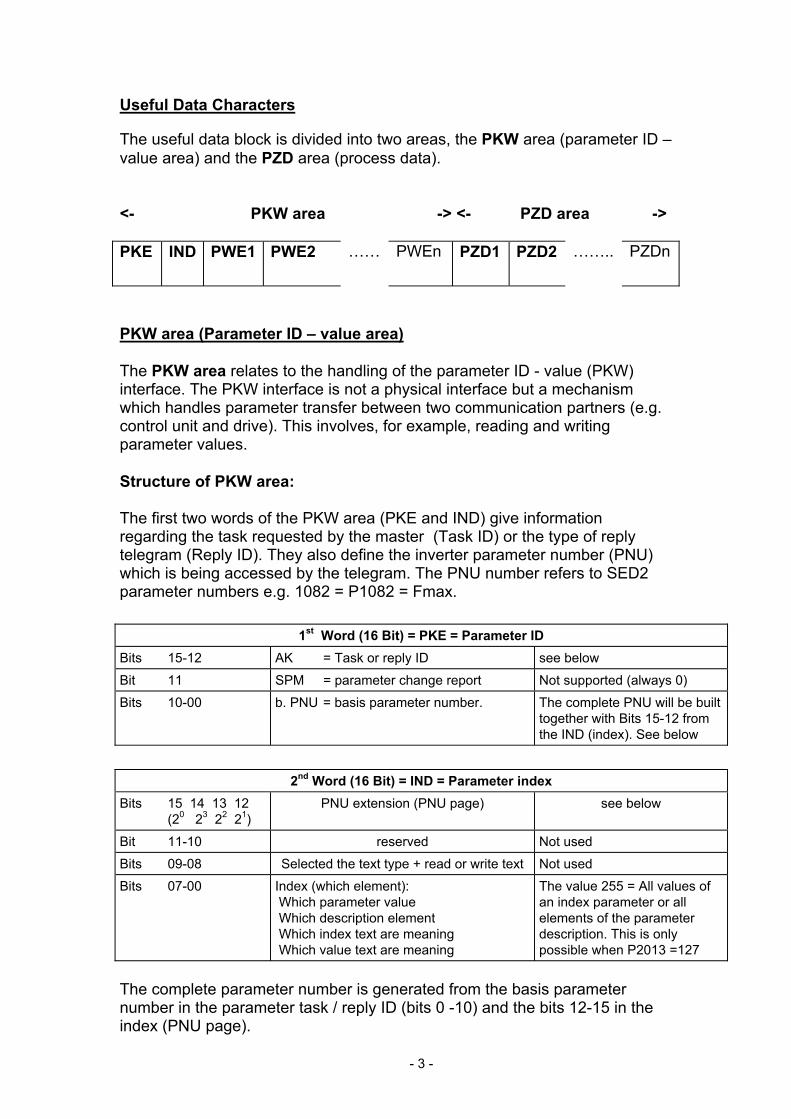
Useful Data Characters The useful data block is divided into two areas, the PKW area (parameter ID – value area) and the PZD area (process data). <- PKW area -> <- PZD area -> PKE IND PWE1 PWE2 …… PWEn PZD1 PZD2 …….. PZDn
PKW area (Parameter ID – value area) The PKW area relates to the handling of the parameter ID - value (PKW) interface. The PKW interface is not a physical interface but a mechanism which handles parameter transfer between two communication partners (e.g. control unit and drive). This involves, for example, reading and writing parameter values. Structure of PKW area: The first two words of the PKW area (PKE and IND) give information regarding the task requested by the master (Task ID) or the type of reply telegram (Reply ID). They also define the inverter parameter number (PNU) which is being accessed by the telegram. The PNU number refers to SED2 parameter numbers e.g. 1082 = P1082 = Fmax.
1st Word (16 Bit) = PKE = Parameter ID Bits 15-12 AK = Task or reply ID see below Bit 11 SPM = parameter change report Not supported (always 0) Bits 10-00 b. PNU = basis parameter number. The complete PNU will be built
together with Bits 15-12 from the IND (index). See below
2nd Word (16 Bit) = IND = Parameter index Bits 15 14 13 12 (20 23 22 21)
PNU extension (PNU page) see below
Bit 11-10 reserved Not used Bits 09-08 Selected the text type + read or write text Not used Bits 07-00 Index (which element):
Which parameter value Which description element Which index text are meaning Which value text are meaning
The value 255 = All values of an index parameter or all elements of the parameter description. This is only possible when P2013 =127
The complete parameter number is generated from the basis parameter number in the parameter task / reply ID (bits 0 -10) and the bits 12-15 in the index (PNU page).
- 3 -

Basis PNU in the task / reply ID
bits 10 - 0 PNU page in the index
bits 15 -12 Complete PNU
= basis PNU + (PNU page * 2000) 0 ... 1999 0 0 ... 1999 0 ... 1999 1 2000 ... 3999 0 ... 1999 2 4000 ... 5999 0 ... 1999 3 6000 ... 3999 0 ... 1999 4 8000 ... 9999
.... ... ... 0 ... 1999 15 30000 ... 31999
Note that bit 15 has the weighting 20 so that this bit must be set for parameter numbers 2000 to 3999. SED2 doesn’t have parameter numbers greater than 3999. The 3rd and 4th words, PWE1 and PWE2 contain the parameter value for the parameter being accessed. There are a number of different parameter value types on SED2, integer values (single or double words), decimal values (given in IEEE float values, always double words) and indexed parameters (referred to here as array values). The meaning of the parameter value is dependent on the parameter value type (middle column) and the setting of P2013 (right hand column)
3rd Word (16 Bit) = PWE1 = 1st parameter value Bits 15 - 0 = Parameter value for non array parameter
= nth parameter value for array parameter and task for nth element
When value of P2013 = 3 (fixed) or = 127 (variable length) and single word parameter.
= 1st parameter value for array parameter and task for all elements
When value of P2013 = 127 (variable length) and single word parameter.
= 0 When value of P2013 = 4 (fixed) and single word parameter.
= High word of parameter value (non array) = High word of nth parameter value for array parameter and task for nth element
When value of P2013 = 4 (fixed) or = 127 (variable length) and double word parameter.
= High word of 1st parameter value for array parameter and task for all elements
When value of P2013 = 127 (variable length) and double word parameter.
Error value Slave Master and replay ID = Task can not be executed.
4th Word (16 Bit) = PWE2 = 2nd parameter value Bits 15 - 0 = 2nd Parameter value for array parameters When value of P2013
- 4 -

and task for all elements = 4 (fixed) or = 127 (variable length) and single word parameter.
= Low word of parameter value (no array) = Low word of nth parameter value for array parameter and task for nth element
When value of P2013 = 4 (fixed) or = 127 (variable length) and double word parameter.
= Low word of 1st parameter value for array parameter and task for all elements
When value of P2013 = 127 (variable length) and 32 bits parameter.
= Next accessible ID Slave Master and replay ID = Task can not be executed. Error value = ID not exist or ID not accessible. When value of P2013 = 127 (variable length)
= Next or previous valid value (16 bit) = High word of the next or previous valid value (32 bit) In the right order: If new value > actual value next valid value. If new value < actual value previous valid value.
Slave Master and replay ID = Task can not be executed. Error value = Value no admissible or New max. /min. value exist. When value of P2013 = 127 (variable length)
Notes: If a parameter value is requested by the master, the values in PWE1 and PWE2 of the master telegram to the inverter are ignored. The meaning of the 3rd and 4th words, PWE1 and PWE2 is dependent on whether variable or fixed length PKW has been selected using P2013. The examples should explain this more clearly later in this section. The SED2 parameter list must be consulted to understand the meaning of the parameter values, and their appropriate settings
- 5 -

Tasks and reply for USS Defined Task ID
Task ID Meaning Reply ID positive negative
0 No task 0 - 1 Request parameter value 1 or 2 7 2 Change parameter value (word) [RAM only] 1 7 or 8 3 Change parameter value (double word) [RAM only] 2 7 or 8 4 Request description element 3 7 5 Change description element (not possible with SED2) - - 6 Request parameter value (array) i.e. indexed parameter 4 or 5 7 7 Change parameter value (array, word) [RAM only] 4 7 or 8 8 Change parameter value (array, double word) [RAM only] 5 7 or 8 9 Request the number of array elements i.e. no. of indices 6 7 10 Reserved - - 11 Save parameter value (array, double word) [RAM and EEPROM] 5 7 or 8 12 Save parameter value (array, word) [RAM and EEPROM] 4 7 or 8 13 Save parameter value (double word) [RAM and EEPROM] 2 7 or 8 14 Save parameter value (word) [RAM and EEPROM] 1 7 or 8 15 Read or change text (not possible with SED2) - -
If the length of PKW is fixed (3 or 4) using P2013, then the Master must always correctly send either 3 or 4 words in the PKW area (if not, the slave will not respond to the telegram). The slave reply PKW will be either 3 or 4 words as well. If a fixed length is used with SED2, this should be 4, as 3 would not be sufficient to support many of the parameters (i.e. double words). For variable length of PKW (127) the Master sends only the necessary number of words for the task in the PKW area. The length of the reply telegram will also only be as long as necessary. The examples shown later should explain this more clearly Defined Reply ID
Reply ID Meaning For Task ID 0 No reply 0 1 Transfer parameter value (word) 1, 2 or 14 2 Transfer parameter value (double word) 1, 3 or 13 3 Transfer description element 4 4 Transfer parameter value (array, word) 6, 7 or 12 5 Transfer parameter value (array, double word) 6, 8 or 11 6 Transfer the number of array elements 9 7 Task cannot be executed (with error value) 1 to 15 8 No change rights for the parameter interface 2, 3, 5, 7, 8, 11 to 14 or
15 (and change text) 9 – 12 Not used -
- 6 -
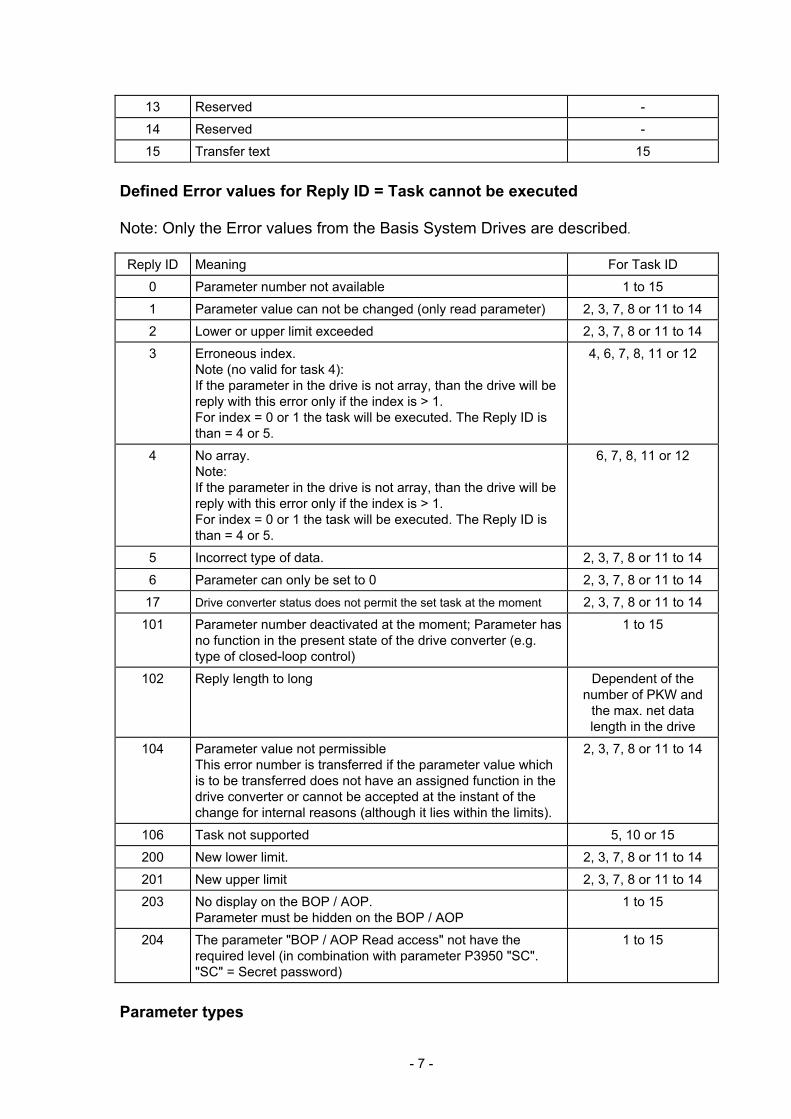
13 Reserved - 14 Reserved - 15 Transfer text 15
Defined Error values for Reply ID = Task cannot be executed Note: Only the Error values from the Basis System Drives are described.
Reply ID Meaning For Task ID 0 Parameter number not available 1 to 15 1 Parameter value can not be changed (only read parameter) 2, 3, 7, 8 or 11 to 14 2 Lower or upper limit exceeded 2, 3, 7, 8 or 11 to 14 3 Erroneous index.
Note (no valid for task 4): If the parameter in the drive is not array, than the drive will be reply with this error only if the index is > 1. For index = 0 or 1 the task will be executed. The Reply ID is than = 4 or 5.
4, 6, 7, 8, 11 or 12
4 No array. Note: If the parameter in the drive is not array, than the drive will be reply with this error only if the index is > 1. For index = 0 or 1 the task will be executed. The Reply ID is than = 4 or 5.
6, 7, 8, 11 or 12
5 Incorrect type of data. 2, 3, 7, 8 or 11 to 14 6 Parameter can only be set to 0 2, 3, 7, 8 or 11 to 14 17 Drive converter status does not permit the set task at the moment 2, 3, 7, 8 or 11 to 14
101 Parameter number deactivated at the moment; Parameter has no function in the present state of the drive converter (e.g. type of closed-loop control)
1 to 15
102 Reply length to long Dependent of the number of PKW and
the max. net data length in the drive
104 Parameter value not permissible This error number is transferred if the parameter value which is to be transferred does not have an assigned function in the drive converter or cannot be accepted at the instant of the change for internal reasons (although it lies within the limits).
2, 3, 7, 8 or 11 to 14
106 Task not supported 5, 10 or 15 200 New lower limit. 2, 3, 7, 8 or 11 to 14 201 New upper limit 2, 3, 7, 8 or 11 to 14 203 No display on the BOP / AOP.
Parameter must be hidden on the BOP / AOP 1 to 15
204 The parameter "BOP / AOP Read access" not have the required level (in combination with parameter P3950 "SC". "SC" = Secret password)
1 to 15
Parameter types
- 7 -

A number of different parameter types are employed on SED2: integer, IEEE float etc. The parameter type is given in the Parmeter List as follows: U16: 16-bit unsigned (single word) U32: 32-bit unsigned (double word) I16: 16-bit integer (single word) I32: 32-bit integer (double word) Float: IEEE float format (double word) I16 and I32 are not used for user parameters on SED2. U32 are double word integers e.g. P0731. Here the integers are separated by a decimal point. The part before the decimal point appears in PWE1 while the part after the decimal point appears in PWE2. PKW Examples: Reading and writing parameter values: It is always possible to use a 4 word PKW in the master even when P2013 =127= variable length. For the examples this will always be used and will be shown in hexadecimal format. The reply PKW telegram will either be 3 or 4 words long depending on the parameter value type. 1. Read a parameter value with parameter number between 0002 and 1999 To read a parameter you should use the Task ID 1 "request parameter value". The Reply ID will be either 1 or 2 (single or double word respectively) or 7 (error). Example: Read parameter P0700. (700 = 2BC (hex)) USS → SED2 : 12BC 0000 0000 0000, requests value of P0700 SED2 → USS : 12BC 0000 0002, the reply tells us this is a single word with value 0002 (hex) Example: Read parameter P1082. (1082 = 43A (hex)) USS → SED2 : 143A 0000 0000 0000, requests value of P1082 SED2 → USS : 243A 0000 4248 0000, the reply tells us this is a double word with value 4248 0000 (IEEE float value). The IEEE float format is as follows: Bit 31 = sign, Bit 23 to Bit 30 = exponent and Bit 0 to Bit 22 = mantissa, with the decimal value being given by: value = ((-1) to power of sign) x (2 to power of (exponent - 127)) x 1.Mantissa). For this example the sign = 0,exponent = 84 (hex) = 132, and the mantissa (1).900000 = [1 + 9/16 + 0/256...] giving (1)x(32)x(1.5625) = 50.00.
- 8 -
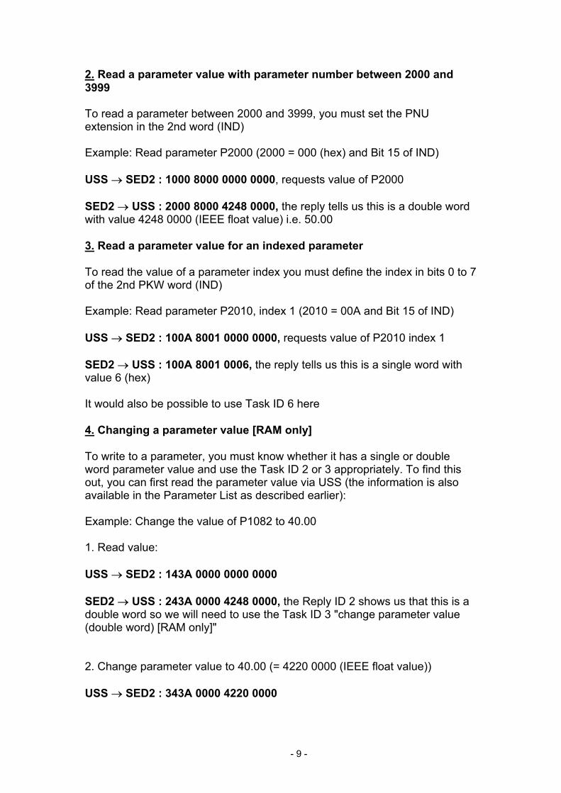
2. Read a parameter value with parameter number between 2000 and 3999 To read a parameter between 2000 and 3999, you must set the PNU extension in the 2nd word (IND) Example: Read parameter P2000 (2000 = 000 (hex) and Bit 15 of IND) USS → SED2 : 1000 8000 0000 0000, requests value of P2000 SED2 → USS : 2000 8000 4248 0000, the reply tells us this is a double word with value 4248 0000 (IEEE float value) i.e. 50.00 3. Read a parameter value for an indexed parameter To read the value of a parameter index you must define the index in bits 0 to 7 of the 2nd PKW word (IND) Example: Read parameter P2010, index 1 (2010 = 00A and Bit 15 of IND) USS → SED2 : 100A 8001 0000 0000, requests value of P2010 index 1 SED2 → USS : 100A 8001 0006, the reply tells us this is a single word with value 6 (hex) It would also be possible to use Task ID 6 here 4. Changing a parameter value [RAM only] To write to a parameter, you must know whether it has a single or double word parameter value and use the Task ID 2 or 3 appropriately. To find this out, you can first read the parameter value via USS (the information is also available in the Parameter List as described earlier): Example: Change the value of P1082 to 40.00 1. Read value: USS → SED2 : 143A 0000 0000 0000 SED2 → USS : 243A 0000 4248 0000, the Reply ID 2 shows us that this is a double word so we will need to use the Task ID 3 "change parameter value (double word) [RAM only]" 2. Change parameter value to 40.00 (= 4220 0000 (IEEE float value)) USS → SED2 : 343A 0000 4220 0000
- 9 -
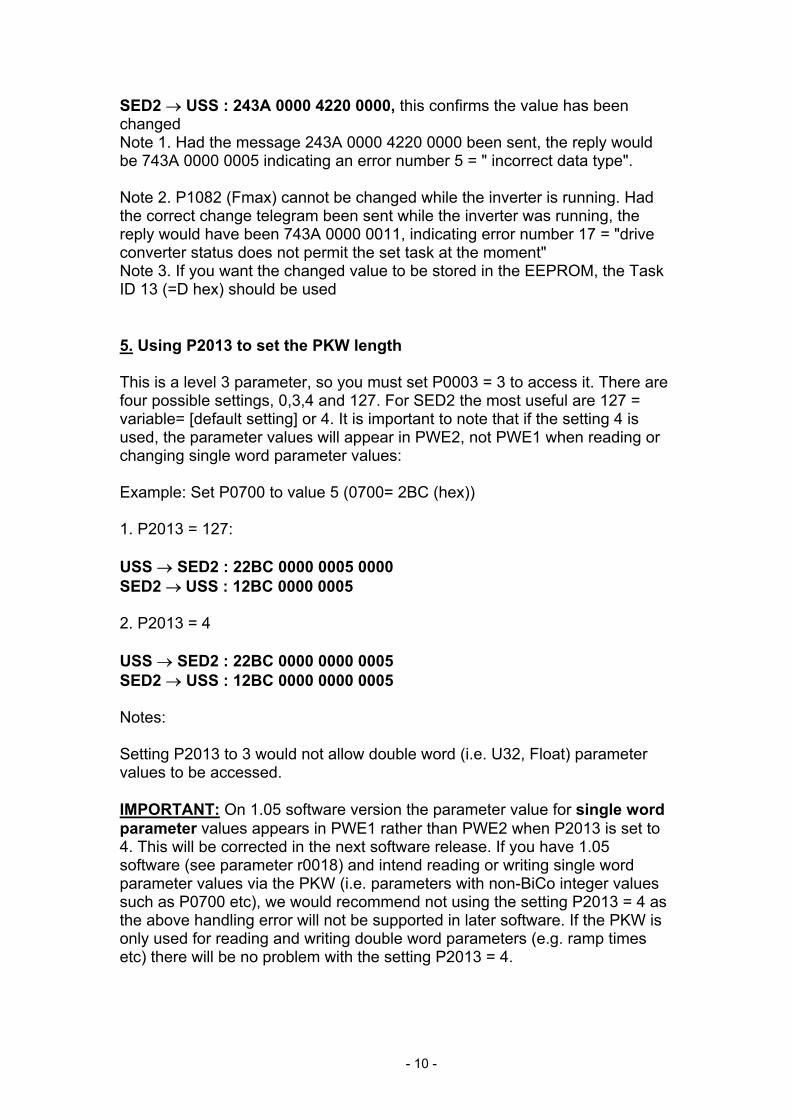
SED2 → USS : 243A 0000 4220 0000, this confirms the value has been changed Note 1. Had the message 243A 0000 4220 0000 been sent, the reply would be 743A 0000 0005 indicating an error number 5 = " incorrect data type". Note 2. P1082 (Fmax) cannot be changed while the inverter is running. Had the correct change telegram been sent while the inverter was running, the reply would have been 743A 0000 0011, indicating error number 17 = "drive converter status does not permit the set task at the moment" Note 3. If you want the changed value to be stored in the EEPROM, the Task ID 13 (=D hex) should be used 5. Using P2013 to set the PKW length This is a level 3 parameter, so you must set P0003 = 3 to access it. There are four possible settings, 0,3,4 and 127. For SED2 the most useful are 127 = variable= [default setting] or 4. It is important to note that if the setting 4 is used, the parameter values will appear in PWE2, not PWE1 when reading or changing single word parameter values: Example: Set P0700 to value 5 (0700= 2BC (hex)) 1. P2013 = 127: USS → SED2 : 22BC 0000 0005 0000 SED2 → USS : 12BC 0000 0005 2. P2013 = 4 USS → SED2 : 22BC 0000 0000 0005 SED2 → USS : 12BC 0000 0000 0005 Notes: Setting P2013 to 3 would not allow double word (i.e. U32, Float) parameter values to be accessed. IMPORTANT: On 1.05 software version the parameter value for single word parameter values appears in PWE1 rather than PWE2 when P2013 is set to 4. This will be corrected in the next software release. If you have 1.05 software (see parameter r0018) and intend reading or writing single word parameter values via the PKW (i.e. parameters with non-BiCo integer values such as P0700 etc), we would recommend not using the setting P2013 = 4 as the above handling error will not be supported in later software. If the PKW is only used for reading and writing double word parameters (e.g. ramp times etc) there will be no problem with the setting P2013 = 4.
- 10 -
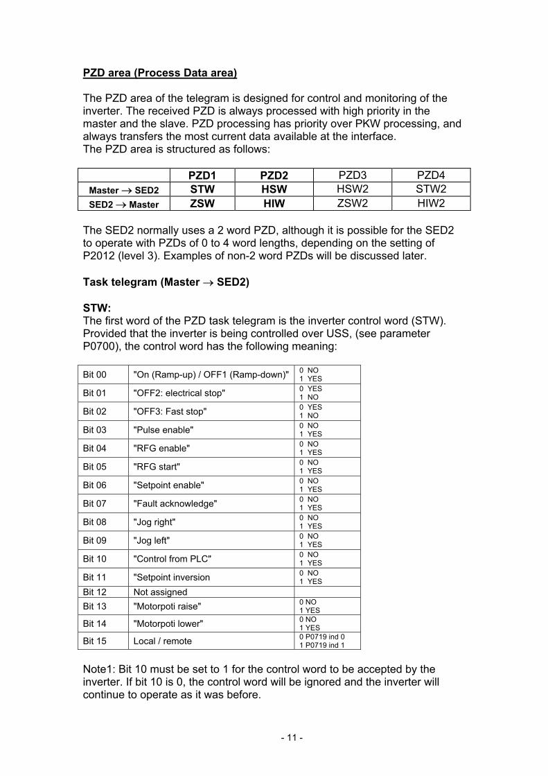
PZD area (Process Data area) The PZD area of the telegram is designed for control and monitoring of the inverter. The received PZD is always processed with high priority in the master and the slave. PZD processing has priority over PKW processing, and always transfers the most current data available at the interface. The PZD area is structured as follows:
PZD1 PZD2 PZD3 PZD4 Master → SED2 STW HSW HSW2 STW2 SED2 → Master ZSW HIW ZSW2 HIW2
The SED2 normally uses a 2 word PZD, although it is possible for the SED2 to operate with PZDs of 0 to 4 word lengths, depending on the setting of P2012 (level 3). Examples of non-2 word PZDs will be discussed later. Task telegram (Master → SED2) STW: The first word of the PZD task telegram is the inverter control word (STW). Provided that the inverter is being controlled over USS, (see parameter P0700), the control word has the following meaning: Bit 00 "On (Ramp-up) / OFF1 (Ramp-down)" 0 NO
1 YES
Bit 01 "OFF2: electrical stop" 0 YES 1 NO
Bit 02 "OFF3: Fast stop" 0 YES 1 NO
Bit 03 "Pulse enable" 0 NO 1 YES
Bit 04 "RFG enable" 0 NO 1 YES
Bit 05 "RFG start" 0 NO 1 YES
Bit 06 "Setpoint enable" 0 NO 1 YES
Bit 07 "Fault acknowledge" 0 NO 1 YES
Bit 08 "Jog right" 0 NO 1 YES
Bit 09 "Jog left" 0 NO 1 YES
Bit 10 "Control from PLC" 0 NO 1 YES
Bit 11 "Setpoint inversion 0 NO 1 YES
Bit 12 Not assigned
Bit 13 "Motorpoti raise" 0 NO 1 YES
Bit 14 "Motorpoti lower" 0 NO 1 YES
Bit 15 Local / remote 0 P0719 ind 0 1 P0719 ind 1
Note1: Bit 10 must be set to 1 for the control word to be accepted by the inverter. If bit 10 is 0, the control word will be ignored and the inverter will continue to operate as it was before.
- 11 -
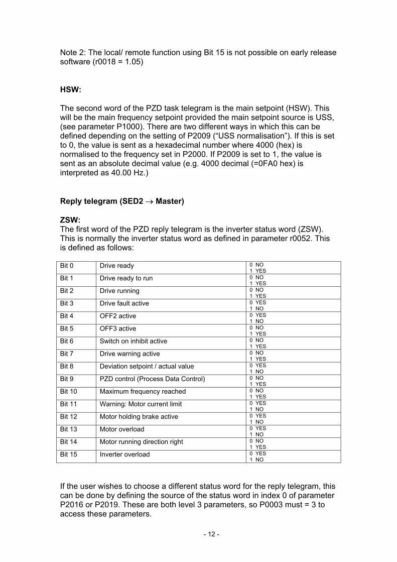
Note 2: The local/ remote function using Bit 15 is not possible on early release software (r0018 = 1.05) HSW: The second word of the PZD task telegram is the main setpoint (HSW). This will be the main frequency setpoint provided the main setpoint source is USS, (see parameter P1000). There are two different ways in which this can be defined depending on the setting of P2009 (“USS normalisation”). If this is set to 0, the value is sent as a hexadecimal number where 4000 (hex) is normalised to the frequency set in P2000. If P2009 is set to 1, the value is sent as an absolute decimal value (e.g. 4000 decimal (=0FA0 hex) is interpreted as 40.00 Hz.) Reply telegram (SED2 → Master) ZSW: The first word of the PZD reply telegram is the inverter status word (ZSW). This is normally the inverter status word as defined in parameter r0052. This is defined as follows: Bit 0 Drive ready 0 NO
1 YES Bit 1 Drive ready to run 0 NO
1 YES Bit 2 Drive running 0 NO
1 YES Bit 3 Drive fault active 0 YES
1 NO Bit 4 OFF2 active 0 YES
1 NO Bit 5 OFF3 active 0 NO
1 YES Bit 6 Switch on inhibit active 0 NO
1 YES Bit 7 Drive warning active 0 NO
1 YES Bit 8 Deviation setpoint / actual value 0 YES
1 NO Bit 9 PZD control (Process Data Control) 0 NO
1 YES Bit 10 Maximum frequency reached 0 NO
1 YES Bit 11 Warning: Motor current limit 0 YES
1 NO Bit 12 Motor holding brake active 0 YES
1 NO Bit 13 Motor overload 0 YES
1 NO Bit 14 Motor running direction right 0 NO
1 YES Bit 15 Inverter overload 0 YES
1 NO If the user wishes to choose a different status word for the reply telegram, this can be done by defining the source of the status word in index 0 of parameter P2016 or P2019. These are both level 3 parameters, so P0003 must = 3 to access these parameters.
- 12 -

HIW: The second word of the PZD reply telegram is the main actual value (HIW). This is normally defined as the inverter output frequency. The normalisation via P2009 (as explained above) also applies to this value. If the user wishes to choose a different actual value for the reply telegram, this can be done by defining the source of the actual value in index 1 of parameter P2016 or P2019, (e.g. the setting 27 would give actual current). These are both level 3 parameters, so P0003 must = 3 to access these parameters. Examples: Run right at 40.00 Hz P0700 must be set to 4 or 5 (USS via RS232 or RS485 respectively) P1000 must be set to 4 or 5 (USS via RS232 or RS485 respectively) Send PZD command 047E 3333 (hex). The reply telegram should be FA31 0000. If the BOP is connected, r0000 should display flashing 40.00 Hz Send PZD command 047F 3333 (hex). The inverter should now run up to 40.00 Hz using the ramp rate set in P1120. To stop the inverter send 047E 0000 (hex) or 047E 3333 (hex) JOG using USS: 1) P0700 must be set to 4 or 5 (USS via RS232 or RS485 respectively) 2) The inverter must be stopped and ready to run. To achieve this send the PZD command 047E 0000 (hex). The inverter should reply with FA31 0000 (hex) 3) To JOG RIGHT send 057E 0000 (hex) 4) To JOG LEFT send 067E 0000 (hex) 5) To STOP send 047E 0000 (hex) To change the JOG direction without stopping use control bits 8 and 9. E.g. 067E 0000 after 057E 0000 will cause the inverter to change JOG direction from left to right without stopping.
- 13 -

Non 2-word PZDs Using P2012 (level 3) it is possible to define the length of the PZD telegram from 0 to 4 words. In this case the PZD3 of the task telegram is another setpoint (HSW2) which could be freely connected using BiCo. Similarly the PZD4 is a second control word for the inverter. This has no specific meaning, but the individual bits can be freely connected using BiCo to realise functions such as “Use Jog ramp times” etc. The example “Using BiCo with USS” should give an indication of how this can be achieved. Using USS Broadcast mode USS Broadcast mode allows all slaves to be addressed with a single telegram, thus allowing groups of inverters to be started and stopped simultaneously. Telegram structure: ADR : bit 5 must be set to 1; other bits should be set to 0 (equivalent to slave address 32 (dec)) PKW : The PKW area must be 4 words long and is used as a mask to define which words and bits of the PZD part are evaluated. The first word defines which PZD words are valid as follows: Bit 0 not used, Bit 1 = PZD1 (control word 1), Bit 2 = PZD2 (setpoint) etc. Word 2 defines which bits in the first control word are evaluated. Words 3 and 4 need only be used where a second control word is being sent in PZD4. For normal 2 word operation this gives the following pattern: 0006 FFFF 0000 0000. The pattern FFFF FFFF FFFF FFFF could also be used here. This masking function conforms to the USS specification and allows greater flexibility in how USS is used in Broadcast mode. For example: If you want full command via broadcast but the setpoint not to be evaluated, 0002 FFFF 0000 0000 should be used (i.e. PZD word 2 not evaluated). This can be very useful for applications where motors should run at different speeds, but should be started simultaneously The individual bits in the control word can similarly be “masked out” e.g. 0006 0401 0000 0000 means that only bit 10 and bit 0 are evaluated: a contol word 0401 / 0400 could then be used to start and stop all inverters. Bit 10 must always be evaluated for the PZD control word to be valid, and must always be set in the bit masking pattern. Masking can be used to selectively enable and disable parts of the PZD control and setpoint words in Broadcast mode as a given process requires.
- 14 -

Note: The PKW cannot be used for reading or writing parameter values in broadcast mode. PZD : Both PZD words are used as normal, and all inverters react simultaneously to the command and setpoint. No reply telegram is generated by the individual slaves in response to a broadcast telegram.
- 15 -

Parameter settings on SED2 for USS The SED2 has two possible serial interfaces which can be used for USS communication: RS232 and RS485. The RS232 is realised using an option module (order no. 6SE6400-1PC00-0AA0). The RS485 interface uses terminals 14 and 15 for P+ and N- respectively. In the parameter documentation, USS via RS485 is sometimes referred to as USS2 while USS via RS232 is referred to as USS1. In each case the telegram structure is the same. The USS parameters usually contain two indices, index 0 for RS485 and index 1 for RS232. Basic Setup In order to communicate via USS, it is necessary to decide whether the RS485 or RS232 interface on the inverter is being used. This will determine which index in the USS parameters are to be set. P0003 = 2 (necessary to access level 2 parameters) P2010 = USS Baud rate. This must correspond to the Baud rate being used by the master. The maximum Baud rate supported is 57600 Baud. P2011 = USS Node address. This is a unique slave address for the inverter. Once these parameters have been set communication is possible. The master will be able to read and write parameters (PKW area) and also monitor the inverter status and actual frequency (PZD area). P0700 = 4 or 5. This allows control of the inverter via USS. The meaning of the bits is explained in the section on “PZD area”. The normal RUN and OFF1 commands are 047F (hex) and 047E (hex) respectively. Other examples are given in the section on “PZD area”. P1000 = 4 or 5. This allows the main setpoint to be sent via USS. By default this is normalised using P2000 so that 4000 (hex) = the value set in P2000. It is possible to normalise this differently using P2009 (level 3) for backwards compatibility with previous MICROMASTER inverters. This will be explained in the next section "Advanced settings". Note P0700 and P1000 are independent of each other and must be set separately as required.
- 16 -
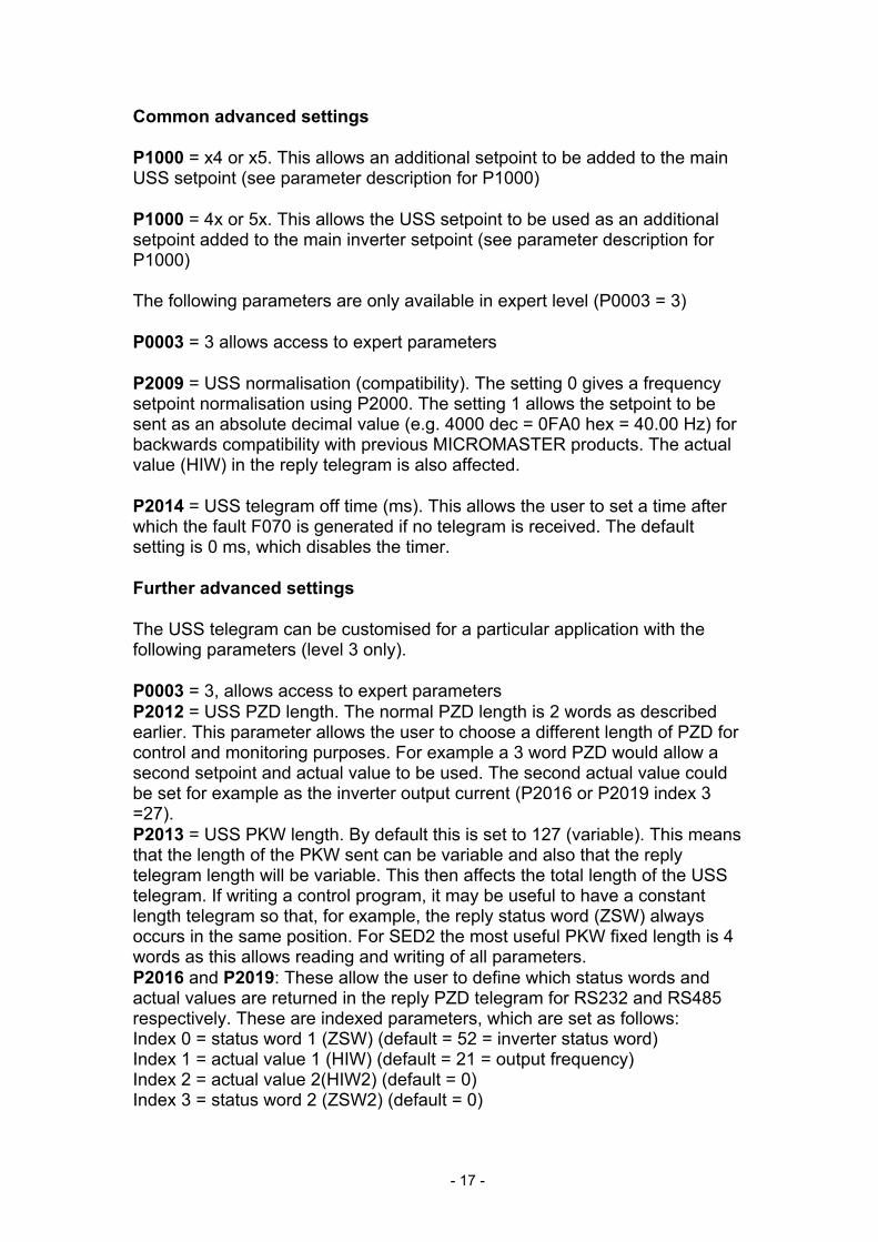
Common advanced settings P1000 = x4 or x5. This allows an additional setpoint to be added to the main USS setpoint (see parameter description for P1000) P1000 = 4x or 5x. This allows the USS setpoint to be used as an additional setpoint added to the main inverter setpoint (see parameter description for P1000) The following parameters are only available in expert level (P0003 = 3) P0003 = 3 allows access to expert parameters P2009 = USS normalisation (compatibility). The setting 0 gives a frequency setpoint normalisation using P2000. The setting 1 allows the setpoint to be sent as an absolute decimal value (e.g. 4000 dec = 0FA0 hex = 40.00 Hz) for backwards compatibility with previous MICROMASTER products. The actual value (HIW) in the reply telegram is also affected. P2014 = USS telegram off time (ms). This allows the user to set a time after which the fault F070 is generated if no telegram is received. The default setting is 0 ms, which disables the timer. Further advanced settings The USS telegram can be customised for a particular application with the following parameters (level 3 only). P0003 = 3, allows access to expert parameters P2012 = USS PZD length. The normal PZD length is 2 words as described earlier. This parameter allows the user to choose a different length of PZD for control and monitoring purposes. For example a 3 word PZD would allow a second setpoint and actual value to be used. The second actual value could be set for example as the inverter output current (P2016 or P2019 index 3 =27). P2013 = USS PKW length. By default this is set to 127 (variable). This means that the length of the PKW sent can be variable and also that the reply telegram length will be variable. This then affects the total length of the USS telegram. If writing a control program, it may be useful to have a constant length telegram so that, for example, the reply status word (ZSW) always occurs in the same position. For SED2 the most useful PKW fixed length is 4 words as this allows reading and writing of all parameters. P2016 and P2019: These allow the user to define which status words and actual values are returned in the reply PZD telegram for RS232 and RS485 respectively. These are indexed parameters, which are set as follows: Index 0 = status word 1 (ZSW) (default = 52 = inverter status word) Index 1 = actual value 1 (HIW) (default = 21 = output frequency) Index 2 = actual value 2(HIW2) (default = 0) Index 3 = status word 2 (ZSW2) (default = 0)
- 17 -

Compatibility with previous MICROMASTER products There are limitations to the compatibility between SED2 USS and previous MICROMASTER products. PZD Control Word The meaning of bits 11 and 12 have changed. In order to get the motor to run right with MM4, bit 11 should be 0 (on MM3 it was 1). To run left, bit 11 should be set to 1 (it was 0 on MM3 and bit 12 was1). i.e. The signal 047F(hex) will cause the inverter to run right and 0C7F(hex) to run left. See table below for comparison: Control Word 1
MM3 MM4 MM4 value
Bit 0 ON (Ramp-up)/ OFF1 (Ramp-down)
Same as MM3
Bit 1 OFF2: electrical stop Same as MM3 Bit 2 OFF3: Fast stop Same as MM3 Bit 3 Pulse enable Same as MM3 Bit 4 Ramp function Generator
(RFG) enable Same as MM3
Bit 5 RFG start Same as MM3 Bit 6 Setpoint enable Same as MM3 Bit 7 Fault acknowledge Same as MM3 Bit 8 Jog right Same as MM3 Bit 9 Jog left Same as MM3 Bit 10 Control from PLC Same as MM3 Bit 11 Right direction Setpoint inversion 0 run right
1 run left Bit 12 Left direction Not used Bit 13 Not used Not used Bit 14 Not used Not used Bit 15 Not used Not used If using MM4 as a replacement for MM3 on an existing machine, setting P1820 = 1 (reverse output phase sequence) will allow the inverter to be operated with the existing control word. The frequency will be displayed as negative for clockwise rotation (RUN RIGHT) in this case. According to USS protocol, the functions of bits 11 to 15 are user defined. This brings MM4 in line with all future Siemens products.
- 18 -

Main Setpoint MM3 parameter P95 “USS Compatibility” setting can be achieved by setting P2009 =1 (level 3, see previous section) Reading and Writing Parameters This is no longer compatible with previous MICROMASTER products. Apart from different parameter numbers, many of the parameter values now use IEEE float format, which necessitates the use double word parameter values and thus requires a longer PKW part of the telegram. This brings SED2 in line with other Siemens inverters such as MasterDrive. Broadcast Mode MM3 operated with a 3 word PKW only. For this reason the PKW area requirement for broadcast mode was not implemented and it was actually possible to change parameter values on all slaves using a broadcast telegram.
- 19 -

Using BiCo with USS The additional BiCo functionality can be used to achieve greater flexibility when controlling the inverter of USS. As was discussed earlier, the SED2 can operate with a PZD length defined by the user in P2012. This means that either one or two control words can be sent from the USS master. If using a single control word (P2012 = default setting = 2), the meaning of the control bits is fixed. However Bit 12 has no assigned function. This can be connected to a function if the user wishes to do this Example: Using USS control with a single control word the user wishes to switch between slow and fast ramp times. This can be achieved by connecting Bit 12 of the control word to the source of JOG ramp time selection (P1124) Parameter settings: P0003 = 3 user access level P0700 = 5 control via RS485 P1060 = JOG ramp up time P1061 = JOG ramp down time P1120 = normal ramp up time P1121 = normal ramp down time P1124 = 2036.12 (connects bit 12 of RS485 control word) P2012 = 2 default setting. With P2012 set to 4, a second control word is possible and the individual bits of this control word can be connected to the source of individual functions. Example If RS 485 is being used Bit 9 of the second control word could be used to enable DC braking as follows: P0003 = 3 P0700 = 5 P1230 = 2037.9 P2012 = 4 Note that while none of the functions of the second control word are preconnected, we recommend using the following bits for the following functions as this corresponds to the description of the second control word displayed in r0056 Bit 0 Fixed frequency selection bit 0 Bit 1 Fixed frequency selection bit 1 Bit 2 Fixed frequency selection bit 2 Bit 8 PID release Bit 9 Enable DC braking Bit13 External fault The remaining bits can be connected as desired
- 20 -