using usb on the lpc1300 - nxp semiconductors · using usb on the lpc1300 as simple as using a uart...
TRANSCRIPT
Using USB on the LPC1300As Simple as Using a UART
David Donley and Pankaj Shrivastava
USB
ARM techcon3 2009
October 21-23, 2009
Agenda
USB Overview
NXP LPC USB Products
LPC13XX On-Chip Driver
HID/MSD Bootloader Demo
–Write a Human Interface Device (HID)
–Flash with Mass Storage Device (MSD)
Bootloader
October 28, 2009
2

3
USB Review
4
What is USB?USB = Universal Serial Bus, V1.0 Released in 1996
Standard Managed by USB Implementers Forum, Inc. at USB.ORG
Designed to Connect Peripherals to PCs
Standard Includes:– Cabling Characteristics (16 feet maximum)– Standardized Connectors– Bus Power– Standardized Hardware Signaling– Standardized Communications Protocol– Standard Device Profiles
Low Cost
Interoperable
Simultaneously Supports Many Peripherals
Ubiquitous (~8 billion ports, sales about 2 billion/year)
5
USB Variants
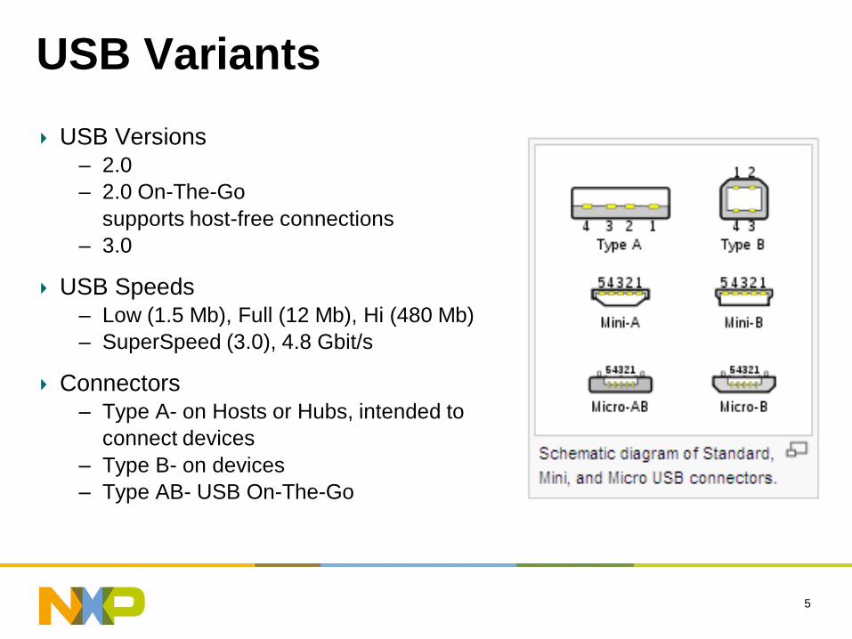
USB Versions– 2.0
– 2.0 On-The-Go
supports host-free connections
– 3.0
USB Speeds– Low (1.5 Mb), Full (12 Mb), Hi (480 Mb)
– SuperSpeed (3.0), 4.8 Gbit/s
Connectors– Type A- on Hosts or Hubs, intended to
connect devices
– Type B- on devices
– Type AB- USB On-The-Go
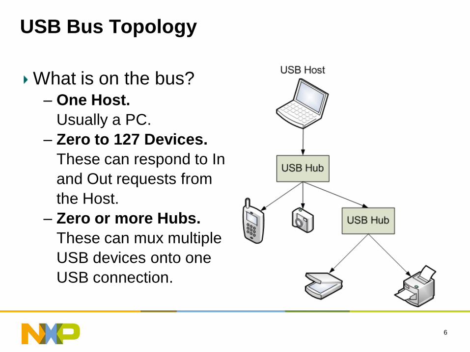
USB Bus Topology
What is on the bus?– One Host.
Usually a PC.
– Zero to 127 Devices.
These can respond to In
and Out requests from
the Host.
– Zero or more Hubs.
These can mux multiple
USB devices onto one
USB connection.
6
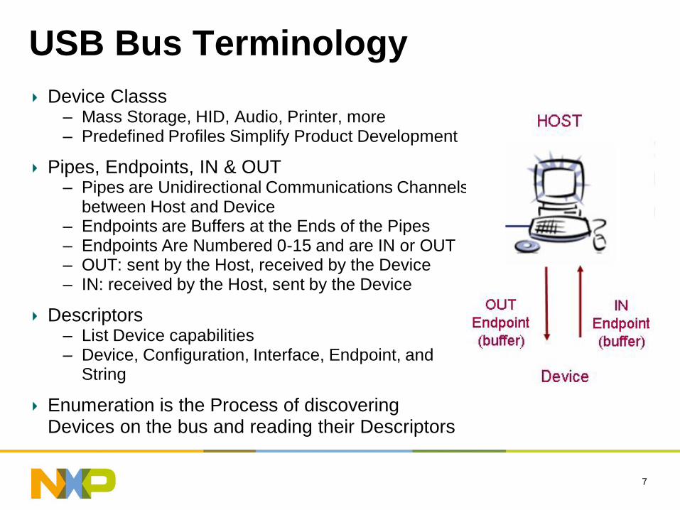
USB Bus Terminology
Device Classs– Mass Storage, HID, Audio, Printer, more– Predefined Profiles Simplify Product Development
Pipes, Endpoints, IN & OUT– Pipes are Unidirectional Communications Channels
between Host and Device– Endpoints are Buffers at the Ends of the Pipes– Endpoints Are Numbered 0-15 and are IN or OUT– OUT: sent by the Host, received by the Device– IN: received by the Host, sent by the Device
Descriptors– List Device capabilities– Device, Configuration, Interface, Endpoint, and
String
Enumeration is the Process of discovering Devices on the bus and reading their Descriptors
7
8
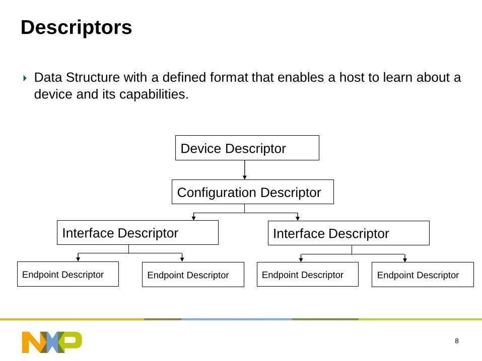
Descriptors
Data Structure with a defined format that enables a host to learn about a
device and its capabilities.
Device Descriptor
Configuration Descriptor
Interface DescriptorInterface Descriptor
Endpoint Descriptor Endpoint DescriptorEndpoint Descriptor Endpoint Descriptor
9
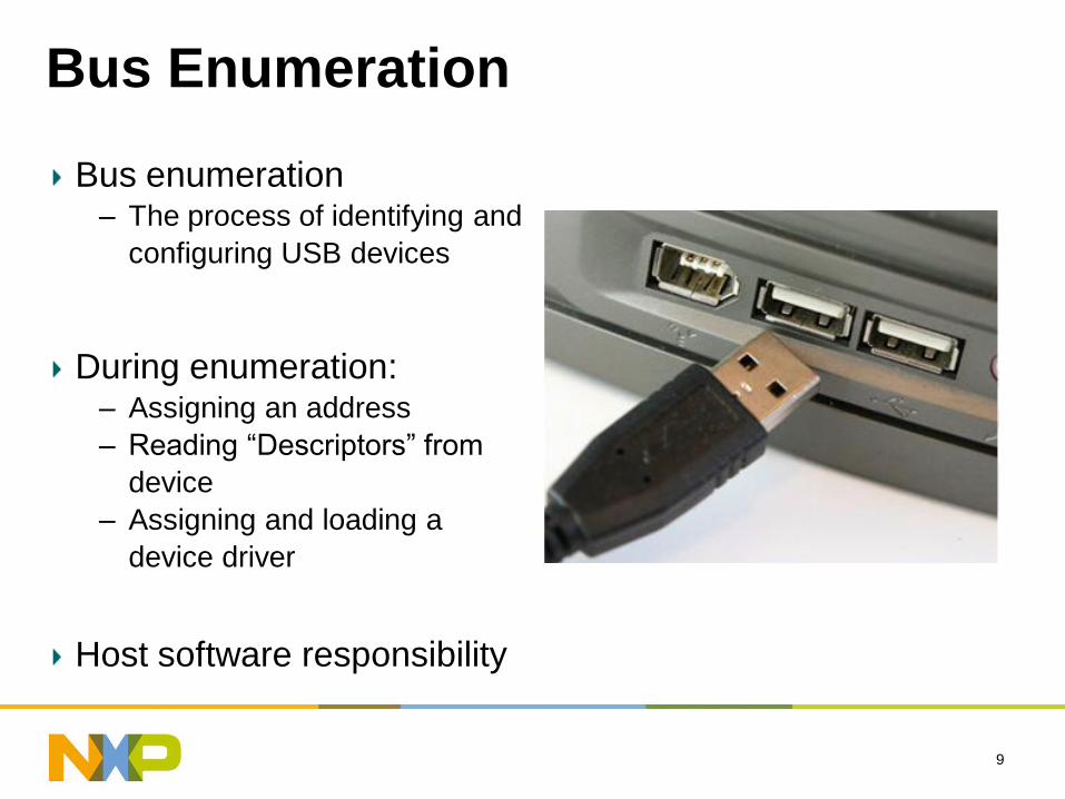
Bus Enumeration
Bus enumeration– The process of identifying and
configuring USB devices
During enumeration:– Assigning an address
– Reading “Descriptors” from
device
– Assigning and loading a
device driver
Host software responsibility
11
NXP LPC USB Products
12
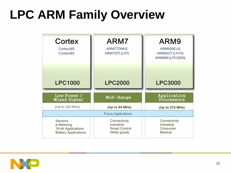
LPC ARM Family Overview
(Up to 120 MHz)
Focus Applications
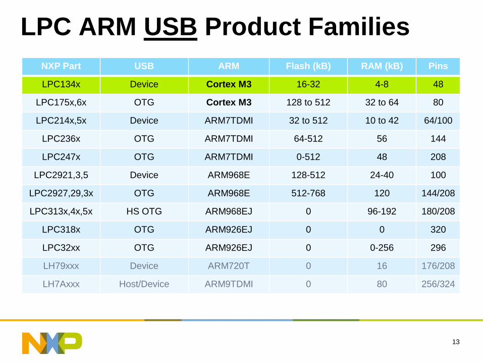
LPC ARM USB Product Families
NXP Part USB ARM Flash (kB) RAM (kB) Pins
LPC134x Device Cortex M3 16-32 4-8 48
LPC175x,6x OTG Cortex M3 128 to 512 32 to 64 80
LPC214x,5x Device ARM7TDMI 32 to 512 10 to 42 64/100
LPC236x OTG ARM7TDMI 64-512 56 144
LPC247x OTG ARM7TDMI 0-512 48 208
LPC2921,3,5 Device ARM968E 128-512 24-40 100
LPC2927,29,3x OTG ARM968E 512-768 120 144/208
LPC313x,4x,5x HS OTG ARM968EJ 0 96-192 180/208
LPC318x OTG ARM926EJ 0 0 320
LPC32xx OTG ARM926EJ 0 0-256 296
LH79xxx Device ARM720T 0 16 176/208
LH7Axxx Host/Device ARM9TDMI 0 80 256/324
13
14
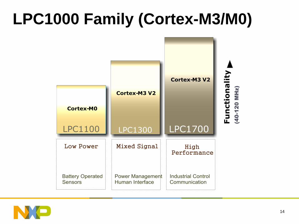
LPC1000 Family (Cortex-M3/M0)
(4
0-1
20
M
Hz)
15
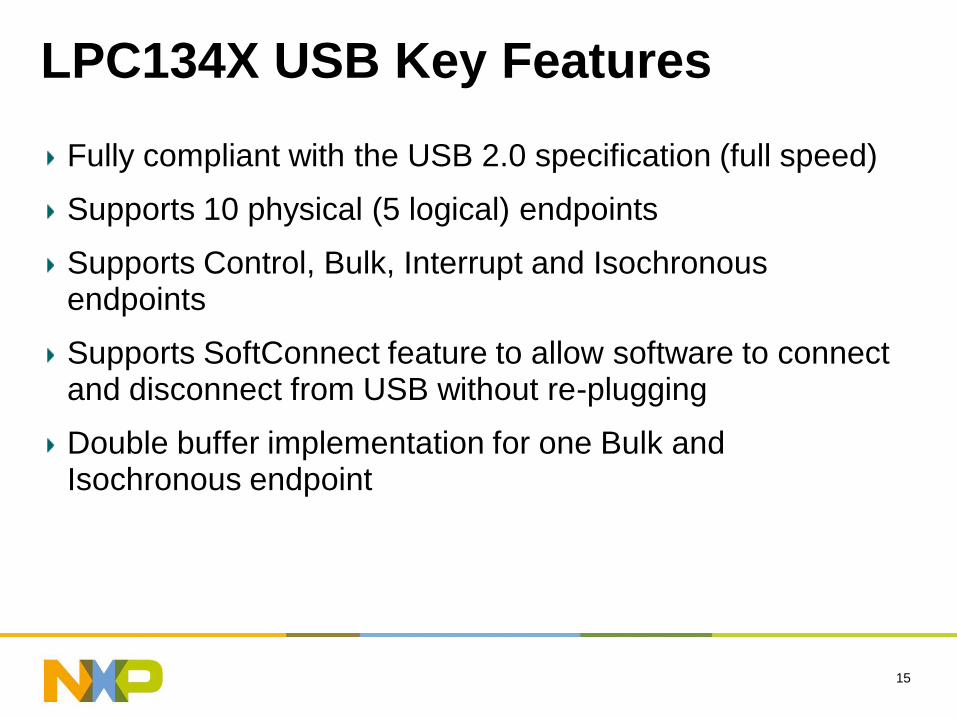
LPC134X USB Key Features
Fully compliant with the USB 2.0 specification (full speed)
Supports 10 physical (5 logical) endpoints
Supports Control, Bulk, Interrupt and Isochronous endpoints
Supports SoftConnect feature to allow software to connect and disconnect from USB without re-plugging
Double buffer implementation for one Bulk and Isochronous endpoint
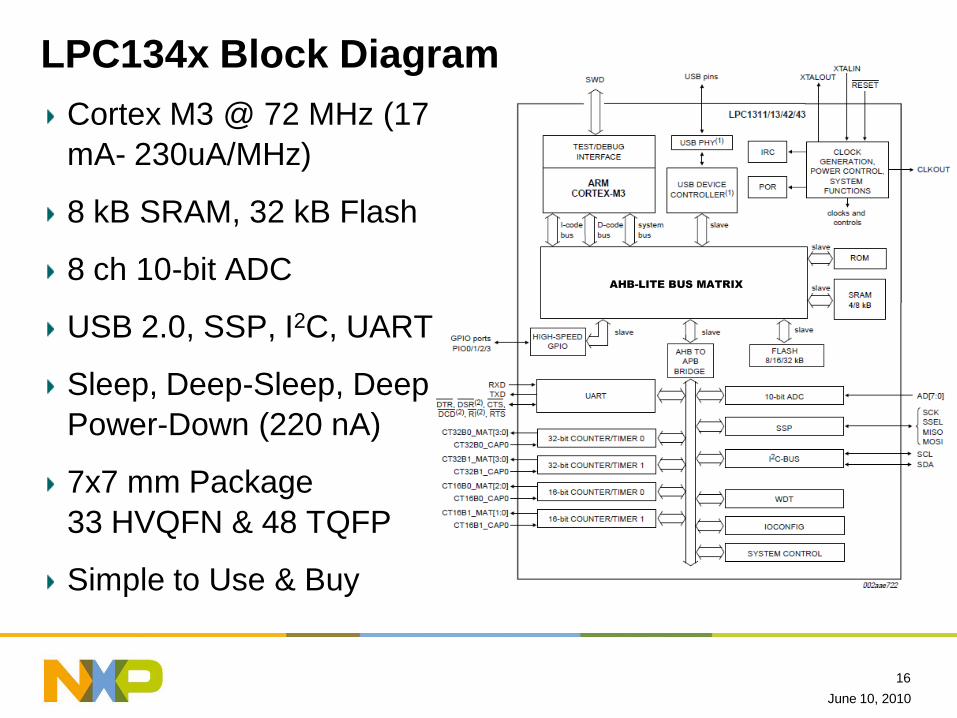
LPC134x Block Diagram
Cortex M3 @ 72 MHz (17
mA- 230uA/MHz)
8 kB SRAM, 32 kB Flash
8 ch 10-bit ADC
USB 2.0, SSP, I2C, UART
Sleep, Deep-Sleep, Deep
Power-Down (220 nA)
7x7 mm Package
33 HVQFN & 48 TQFP
Simple to Use & Buy
June 10, 2010
16
AHB-LITE BUS MATRIX
17
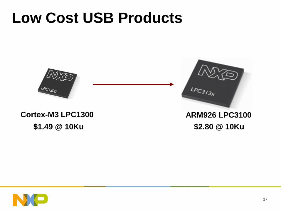
Low Cost USB Products
Cortex-M3 LPC1300 ARM926 LPC3100
$2.80 @ 10Ku$1.49 @ 10Ku
18
LPC13XX On-Chip Driver
19
USB Product ChallengesImplementing USB Device Functions
– USB Hardware Initialization– USB Enumeration Handshake– Data Translation/Formatting– Responding to USB Overhead
• Descriptor Requests• Configuration Commands• Status Reporting
– Firmware Updates• Bootloader w/ Flash Programming• Bootloader Host Software
Getting USB VID/PID
Possible Tool Vendor Porting Issues with Silicon Vendor’s Code
C Programming Issues with Non-Standard 8-bit Architectures with RAM Banking, Stack Depth Limits, and Incompatible Pointer Types
20
LPC13XX On-Chip Driver Benefits
Implements USB Device Functions
Host Driverless USB Bootloader also On-Chip
Up to 6KB Extra Flash Memory for your Product’s Firmware
Binary ROM Driver Circumvents Potential Tool Vendor Porting Issues
Tested and Validated USB Certified Code Reduces Product Development Risk
No Banking, Stack Depth, or Pointer Type Issues
21
LPC13XX On-Chip Driver FeaturesRobustness- Bootloader and Driver Stored In ROM
Up to 6KB Extra Flash Memory for your Product’s Firmware
Bootloader ROM Features:– UART In-System Programming– Driverless USB In System Programming (MSD)– In Application Programming (Flash Programming Library)
On Chip USB Driver Features:– Clock and Pin Initialization– USB Initialization– USB Connect– USB Interrupt Handler
Supported Device Classes:– Mass Storage– Human Interface Device
22
LPC13XX USB VID/PID
– USB Devices Uniquely Identified by a Vendor ID
(VID) and Product ID (PID) Which Are 16-bit
Numbers
– The USB Implementers Forum Assigns VIDs,
Which are Required for a USB Logo
– Vendor ID: $2000 one-time cost
– USB Logo Licensee: $2000 for a 2-year term
– USB-IF Membership: $4000/year
– With your own VID, you may produce 65,536
distinct products
23
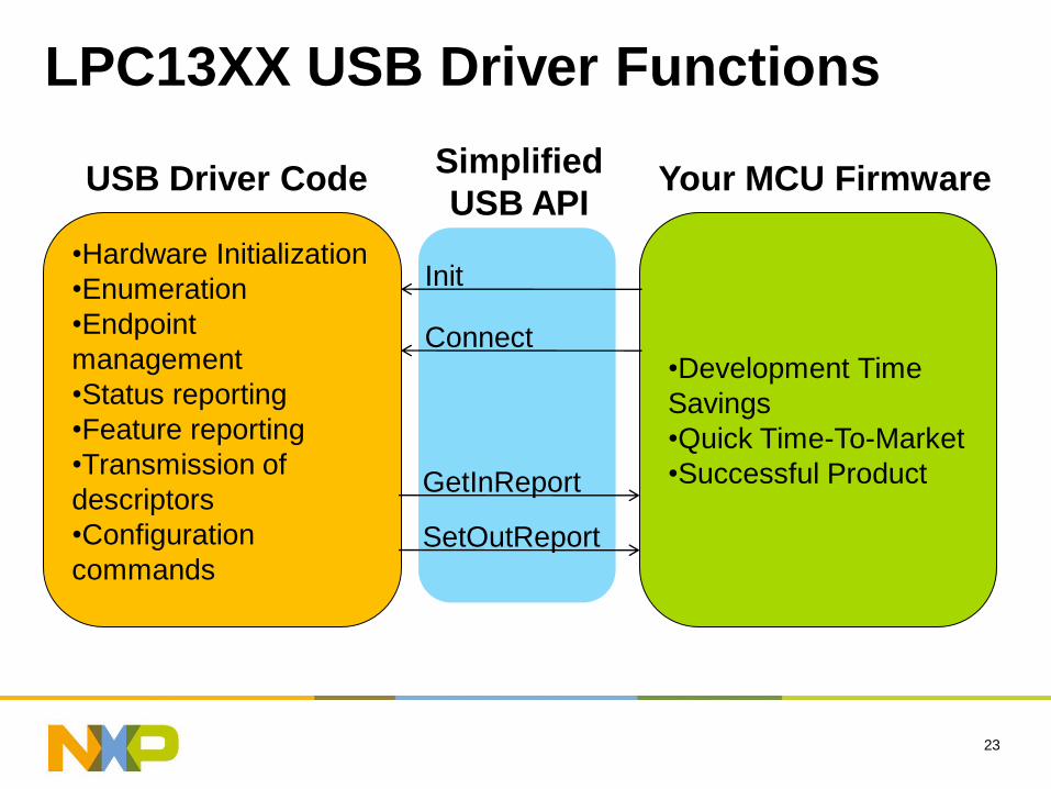
LPC13XX USB Driver Functions
•Hardware Initialization
•Enumeration
•Endpoint
management
•Status reporting
•Feature reporting
•Transmission of
descriptors
•Configuration
commands
•Development Time
Savings
•Quick Time-To-Market
•Successful Product
Init
Connect
GetInReport
SetOutReport
USB Driver Code Your MCU FirmwareSimplified
USB API
24
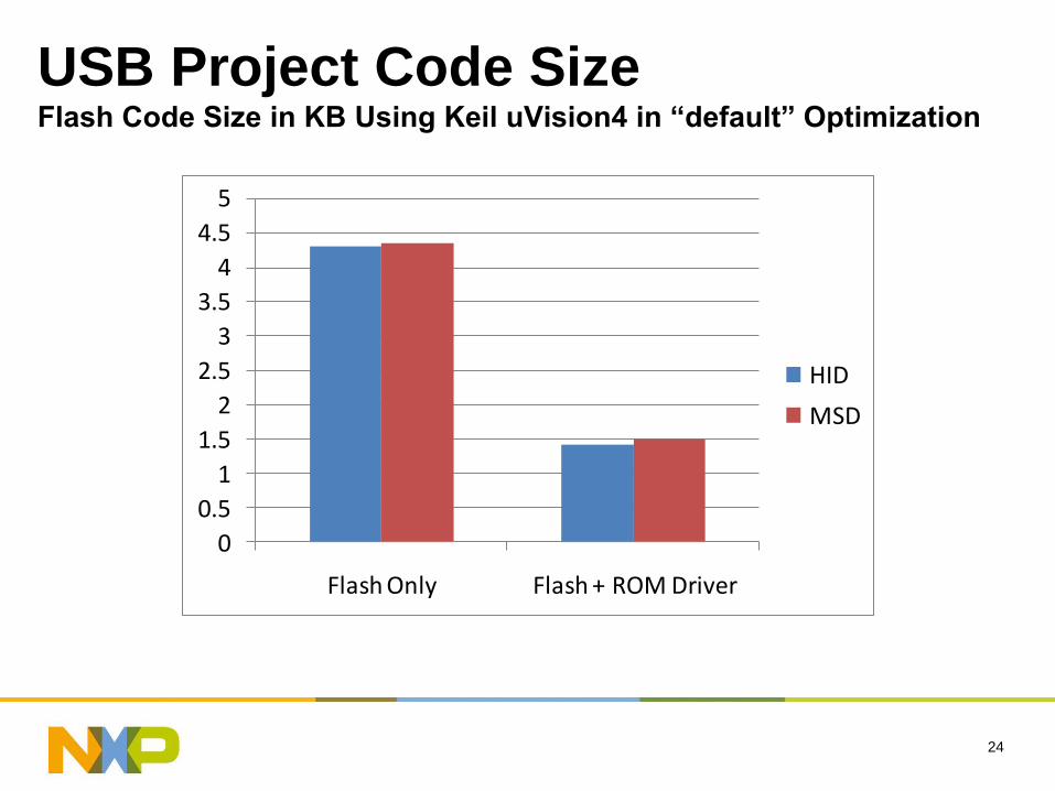
USB Project Code SizeFlash Code Size in KB Using Keil uVision4 in “default” Optimization
0
0.5
1
1.5
2
2.5
3
3.5
4
4.5
5
Flash Only Flash + ROM Driver
HID
MSD
25
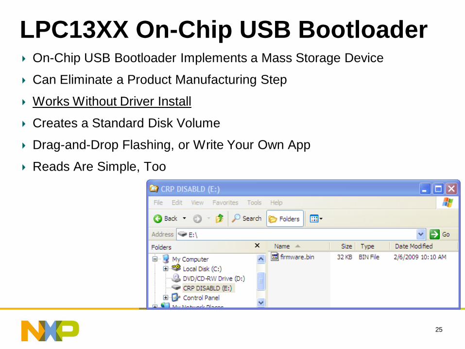
LPC13XX On-Chip USB BootloaderOn-Chip USB Bootloader Implements a Mass Storage Device
Can Eliminate a Product Manufacturing Step
Works Without Driver Install
Creates a Standard Disk Volume
Drag-and-Drop Flashing, or Write Your Own App
Reads Are Simple, Too
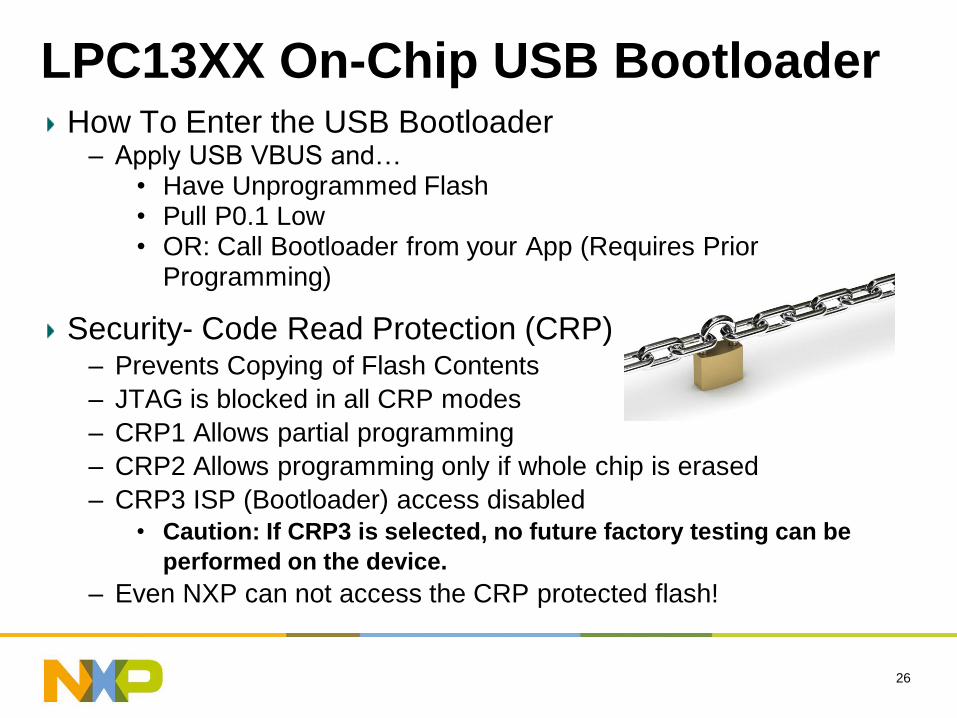
How To Enter the USB Bootloader– Apply USB VBUS and…
• Have Unprogrammed Flash• Pull P0.1 Low• OR: Call Bootloader from your App (Requires Prior
Programming)
Security- Code Read Protection (CRP)– Prevents Copying of Flash Contents
– JTAG is blocked in all CRP modes
– CRP1 Allows partial programming
– CRP2 Allows programming only if whole chip is erased
– CRP3 ISP (Bootloader) access disabled• Caution: If CRP3 is selected, no future factory testing can be
performed on the device.
– Even NXP can not access the CRP protected flash!
26
LPC13XX On-Chip USB Bootloader
27
HID/MSD Bootloader Demo
–Write a Human Interface Device (HID)
–Flash with Mass Storage Device (MSD)
Bootloader
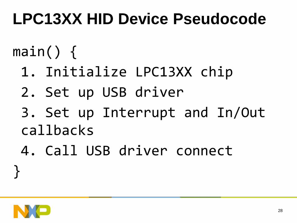
LPC13XX HID Device Pseudocode
main() {
1. Initialize LPC13XX chip
2. Set up USB driver
3. Set up Interrupt and In/Out callbacks
4. Call USB driver connect
}
28
LPC13XX HID Device Code
29
/*
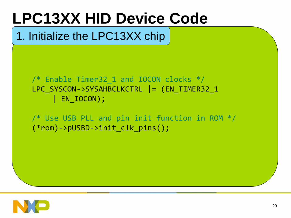
/* Enable Timer32_1 and IOCON clocks */LPC_SYSCON->SYSAHBCLKCTRL |= (EN_TIMER32_1
| EN_IOCON);
/* Use USB PLL and pin init function in ROM */(*rom)->pUSBD->init_clk_pins();
1. Initialize the LPC13XX chip
LPC13XX HID Device Code
30
/*
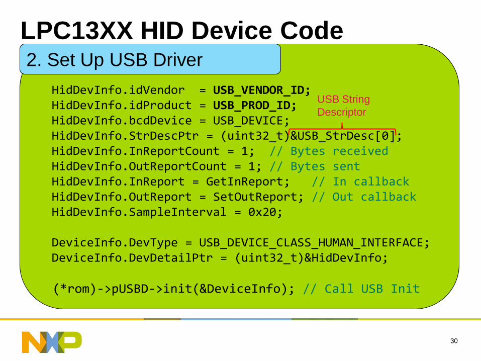
HidDevInfo.idVendor = USB_VENDOR_ID;HidDevInfo.idProduct = USB_PROD_ID;HidDevInfo.bcdDevice = USB_DEVICE; HidDevInfo.StrDescPtr = (uint32_t)&USB_StrDesc[0];HidDevInfo.InReportCount = 1; // Bytes receivedHidDevInfo.OutReportCount = 1; // Bytes sentHidDevInfo.InReport = GetInReport; // In callbackHidDevInfo.OutReport = SetOutReport; // Out callbackHidDevInfo.SampleInterval = 0x20;
DeviceInfo.DevType = USB_DEVICE_CLASS_HUMAN_INTERFACE;DeviceInfo.DevDetailPtr = (uint32_t)&HidDevInfo;
(*rom)->pUSBD->init(&DeviceInfo); // Call USB Init
2. Set Up USB Driver
USB String
Descriptor
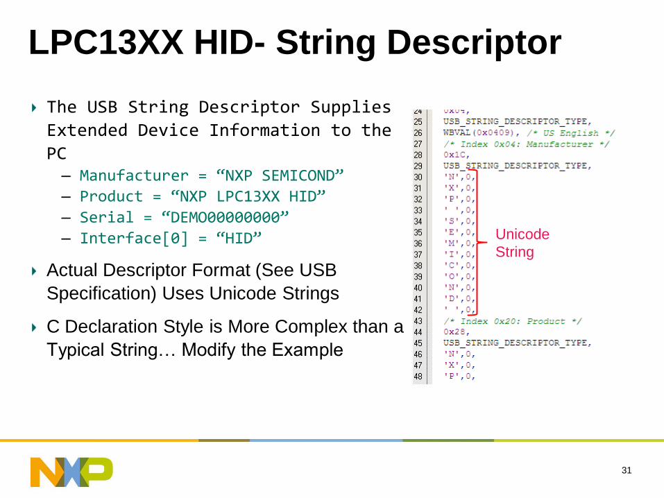
LPC13XX HID- String Descriptor
The USB String Descriptor Supplies
Extended Device Information to the
PC– Manufacturer = “NXP SEMICOND”
– Product = “NXP LPC13XX HID”
– Serial = “DEMO00000000”
– Interface[0] = “HID”
Actual Descriptor Format (See USB
Specification) Uses Unicode Strings
C Declaration Style is More Complex than a
Typical String… Modify the Example
31
Unicode
String
LPC13XX HID Device Code
32
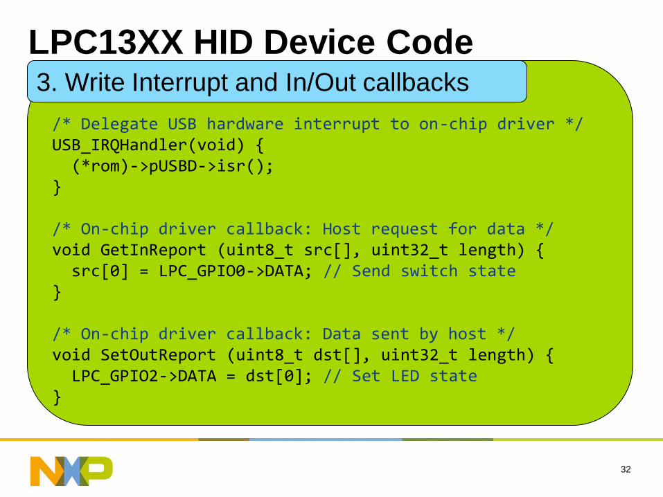
/*
/* Delegate USB hardware interrupt to on-chip driver */USB_IRQHandler(void) {(*rom)->pUSBD->isr();
}
/* On-chip driver callback: Host request for data */void GetInReport (uint8_t src[], uint32_t length) {src[0] = LPC_GPIO0->DATA; // Send switch state
}
/* On-chip driver callback: Data sent by host */void SetOutReport (uint8_t dst[], uint32_t length) {LPC_GPIO2->DATA = dst[0]; // Set LED state
}
3. Write Interrupt and In/Out callbacks
LPC13XX HID Device Code
33
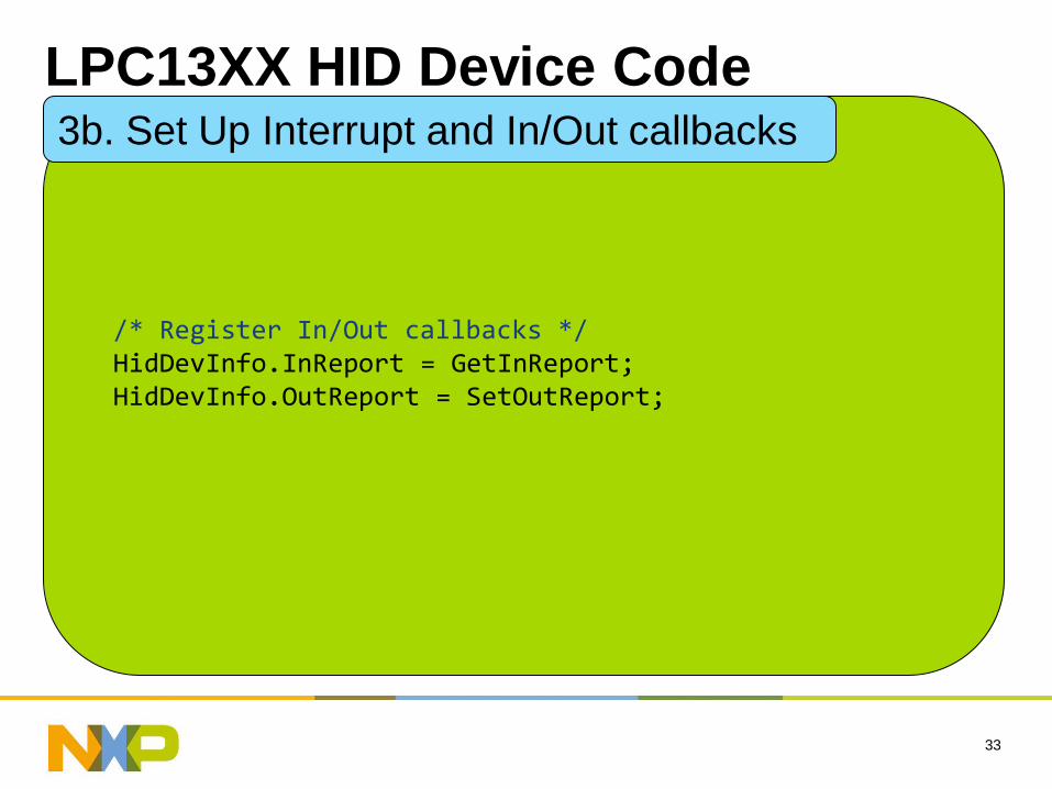
/*
/* Register In/Out callbacks */HidDevInfo.InReport = GetInReport;HidDevInfo.OutReport = SetOutReport;
3b. Set Up Interrupt and In/Out callbacks
LPC13XX HID Device Code
34
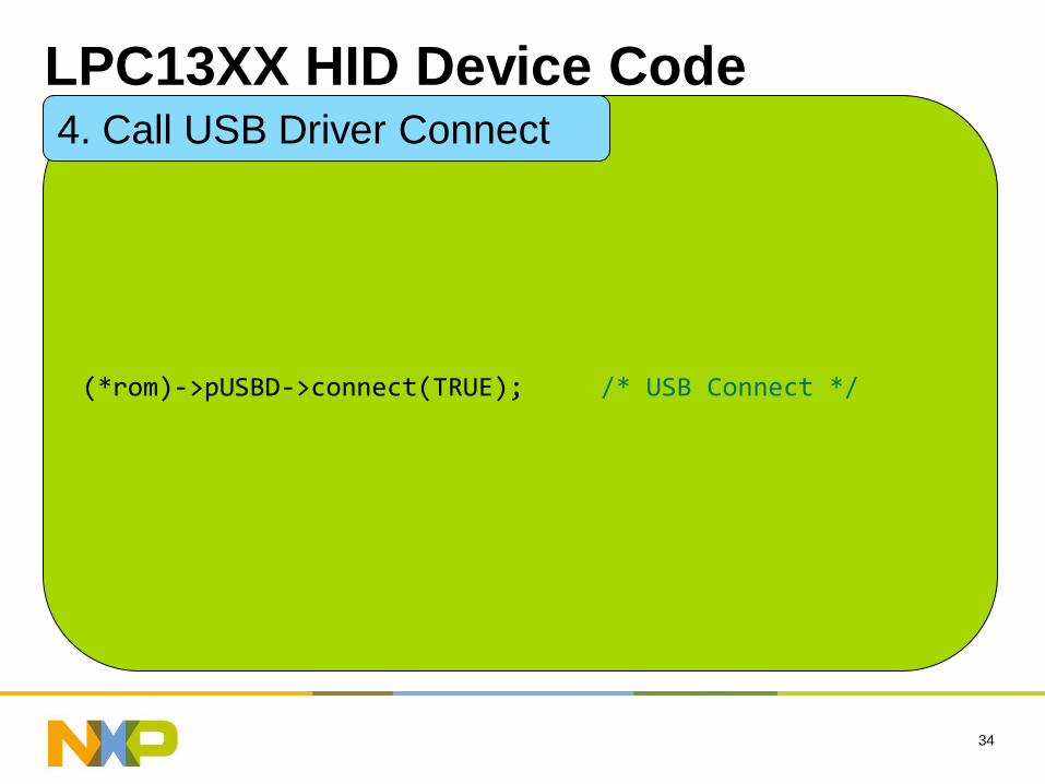
/*
(*rom)->pUSBD->connect(TRUE); /* USB Connect */
4. Call USB Driver Connect
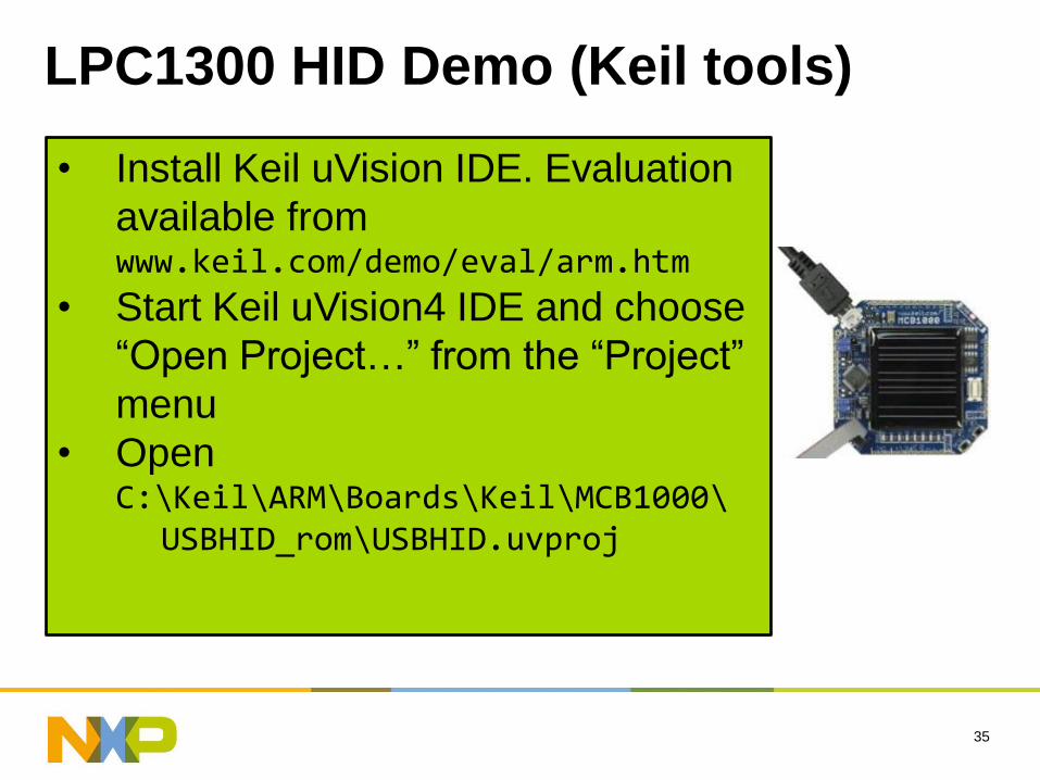
LPC1300 HID Demo (Keil tools)
35
• Install Keil uVision IDE. Evaluation
available from www.keil.com/demo/eval/arm.htm
• Start Keil uVision4 IDE and choose
“Open Project…” from the “Project”
menu
• Open C:\Keil\ARM\Boards\Keil\MCB1000\
USBHID_rom\USBHID.uvproj
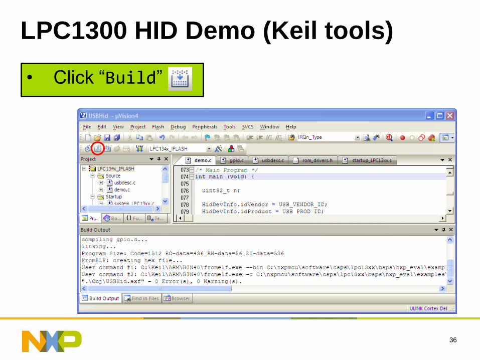
LPC1300 HID Demo (Keil tools)
36
• Click “Build”
LPC1300 HID Demo (Keil tools)
37
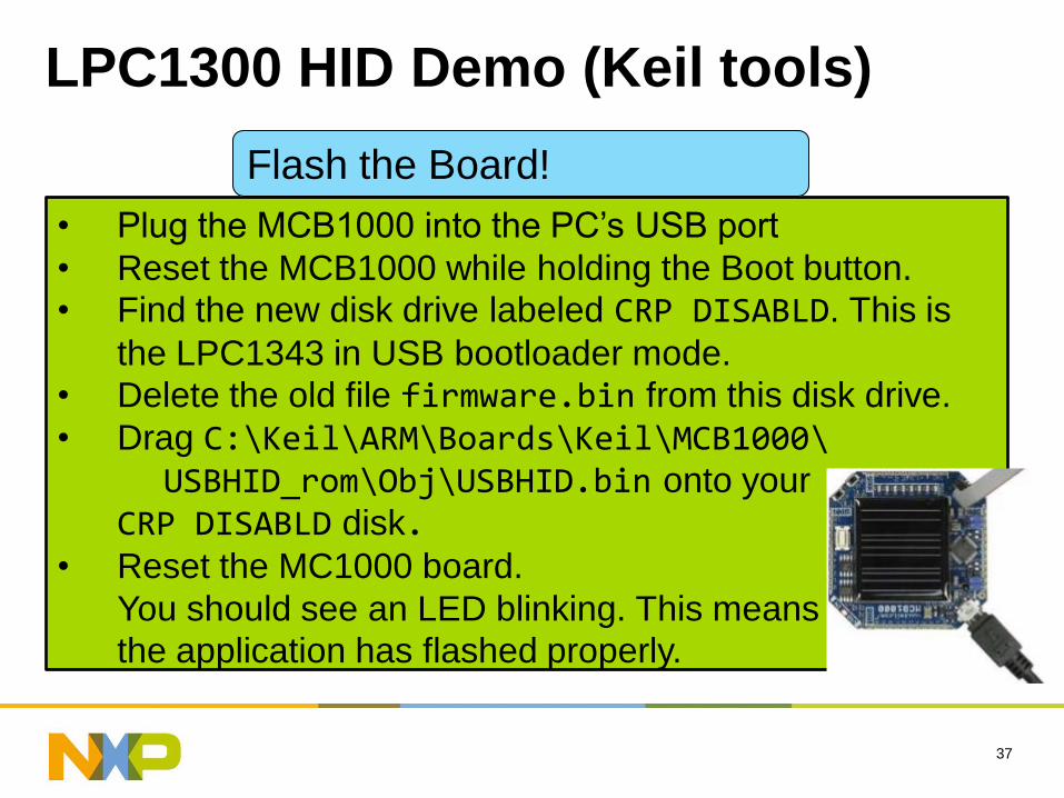
• Plug the MCB1000 into the PC’s USB port
• Reset the MCB1000 while holding the Boot button.
• Find the new disk drive labeled CRP DISABLD. This is
the LPC1343 in USB bootloader mode.
• Delete the old file firmware.bin from this disk drive.
• Drag C:\Keil\ARM\Boards\Keil\MCB1000\USBHID_rom\Obj\USBHID.bin onto your
CRP DISABLD disk.• Reset the MC1000 board.
You should see an LED blinking. This means
the application has flashed properly.
Flash the Board!
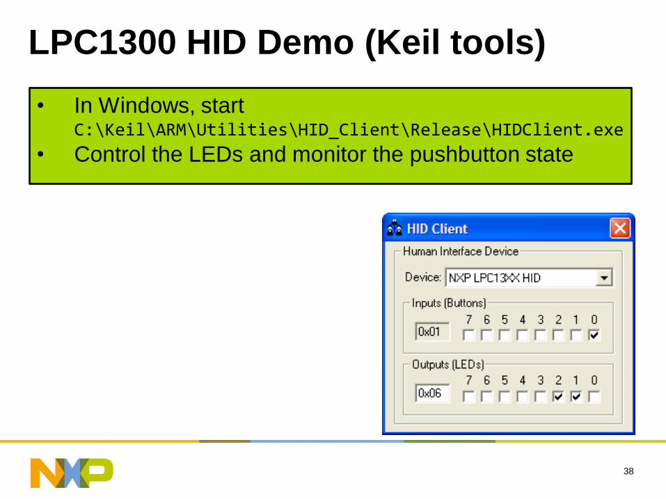
LPC1300 HID Demo (Keil tools)
38
• In Windows, start C:\Keil\ARM\Utilities\HID_Client\Release\HIDClient.exe
• Control the LEDs and monitor the pushbutton state
39
Conclusion
NXP LPC13XX MCUs Ship with Drivers In On-Chip ROM
Drivers Implement USB Device Functions
USB Bootloader also On-Chip
Up to 6KB Extra Flash Memory for your Product’s Firmware
Binary ROM Driver Circumvents Potential Tool Vendor Porting Issues
Tested and Validated USB Code Reduces Product Development Risk and Firmware Development Time
32-bit Architecture Eases Software Development Headaches

June 10, 2010
40
Thank you!