using the common access card for remote access vpn … · in its place, only certificate-based...
TRANSCRIPT
Design Guide
All contents are Copyright © 1992–2007 Cisco Systems, Inc. All rights reserved. This document is Cisco Public Information. Page 1 of 53
Using the Common Access Card for Remote Access VPN with the ASA 5500
Executive Summary
The Department of Defense (DoD) has implemented the Common Access Card (CAC) for all user
authentications. Beginning in the summer of 2006, the CAC is mandatory for user authentication.
Most DoD installations have converted their Active Directories to accept the CAC for user logons.
This paper details the steps necessary to enable ASA 5500 support for the DoD Common Access
Card (CAC) when it is integrated with Active Directory (AD) to provide Smart Card Logon. When
Smart Card Logon is enabled, several challenges are presented as the typical authentication and
authorization credentials are eliminated. In its place, only certificate-based authentication can be
used to allow the Adaptive Security Appliance (ASA) to permit users to remotely access Virtual
Private Network (VPN). This white paper focuses on implementing all of the functionality natively
on the ASA 5500 with the Cisco VPN Client. Other solutions exist or may be possible using Layer
2 Tunneling Protocol/IP Security (L2TP/IPSec) with the Microsoft Client, or by introducing Remote
Authentication Dial-In User Service (RADIUS) to provide the authorization functions.
This document focuses on the basic configuration settings for enabling CAC Authentication on the
ASA 5500. The ASA 5500 provides a multitude of additional features that should be explored to
further enhance the end-user experience and to help secure the DoD Enterprise. For more
information on the advanced configuration settings on the ASA 5500, visit
http://www.cisco.com/en/US/products/ps6120/products_configuration_guide_book09186a00806a6
1b0.html.
DoD Public Key Infrastructure and Common Access Car ds
Public Key Infrastructure Overview
Public Key Infrastructure (PKI) offers a scalable method of securing networks, reducing
management overhead, and simplifying the deployment of network infrastructures by deploying
security protocols including IPSec, Secure Shell (SSH), and Secure Socket Layer (SSL).
PKI is a system that manages encryption keys and identity information for the human and
mechanical components of a network that participates in secured communications.
For a person or a piece of equipment to enroll in a PKI, the software on a user's computer
generates a pair of encryption keys that will be used in secured communications: a public and a
private key. In the case of the Common Access Card, the keys and certificates are stored on the
CAC Smart Card.
The private key is never distributed or revealed. Conversely, the public key is freely distributed to
any party that negotiates a secure communication. During the enrollment process (as shown in
Figure 1), the user's public key is sent in the certificate request to the Certificate Authority (CA),
which is responsible for the portion of the organization to which that entity belongs. The user sends
the public key to the registration component of the CAs. Subsequently, the administrator approves
the request and the CA generates the user's certificate. After the user receives a certificate and
Design Guide
All contents are Copyright © 1992–2007 Cisco Systems, Inc. All rights reserved. This document is Cisco Public Information. Page 2 of 53
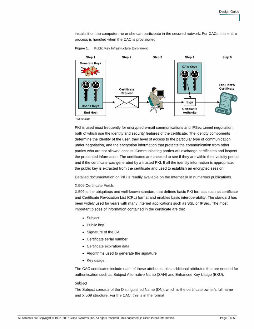
installs it on the computer, he or she can participate in the secured network. For CACs, this entire
process is handled when the CAC is provisioned.
Figure 1. Public Key Infrastructure Enrollment
PKI is used most frequently for encrypted e-mail communications and IPSec tunnel negotiation,
both of which use the identity and security features of the certificate. The identity components
determine the identity of the user, their level of access to the particular type of communication
under negotiation, and the encryption information that protects the communication from other
parties who are not allowed access. Communicating parties will exchange certificates and inspect
the presented information. The certificates are checked to see if they are within their validity period
and if the certificate was generated by a trusted PKI. If all the identity information is appropriate,
the public key is extracted from the certificate and used to establish an encrypted session.
Detailed documentation on PKI is readily available on the Internet or in numerous publications.
X.509 Certificate Fields
X.509 is the ubiquitous and well-known standard that defines basic PKI formats such as certificate
and Certificate Revocation List (CRL) format and enables basic interoperability. The standard has
been widely used for years with many Internet applications such as SSL or IPSec. The most
important pieces of information contained in the certificate are the:
● Subject
● Public key
● Signature of the CA
● Certificate serial number
● Certificate expiration data
● Algorithms used to generate the signature
● Key usage.
The CAC certificates include each of these attributes, plus additional attributes that are needed for
authentication such as Subject Alternative Name (SAN) and Enhanced Key Usage (EKU).
Subject
The Subject consists of the Distinguished Name (DN), which is the certificate owner’s full name
and X.509 structure. For the CAC, this is in the format:

Design Guide
All contents are Copyright © 1992–2007 Cisco Systems, Inc. All rights reserved. This document is Cisco Public Information. Page 3 of 53
CN=LastName.FirstName.MiddleName.EDI/PI,OU=CONTRACTOR,OU=DoD,OU=PKI,OU=
DoD,O=U.S. Government,C=US
Note: The CONTRACTOR designation only appears on the CACs of DoD Contractors.
There is little information to identify where the user belongs. It would be very desirable for the
X.509 structure to include some type of information defining the user’s organization.
Subject Alternative Name
On the CAC, the SAN field contains two fields. The first field is the email address of the user and
the second is called the Principal Name (PN). The PN is an important field. This is the field that is
used when the CAC is integrated into the Active Directory. The data in this field is in the format
EDI/PI@mil.
The SAN field exists on two certificates on the CAC, the Signature Certificate and the Encryption
Certificate. However, only the Signature Certificate contains the Principal Name field. CAC
certificates are detailed in the CAC Certificate Section.
Enhanced Key Usage
The EKU field contains additional uses for a digital certificate. On the CAC, the certificate that is
used for Active Directory Smart Card Logon contains this attribute with the Object Identifier (OID)
for Smart Card Logon (1.3.6.1.4.1.311.20.2.2). This field is different from the Key Usage (KU) field,
which defines the primary purposes of the certificate and is backwards compatible with earlier
versions of X.509.
CAC Components
The CAC provides two-factor authentication. To unlock the certificates on the CAC, the user must
place the physical CAC in a reader and enter a Personal Identification Number (PIN). This unlocks
the private keys stored on CAC. The private keys are never exported or placed on the workstation.
CAC Reader
The CAC Reader is an International Standards Organization (ISO) 7816 standard Smart Card
Reader. The user must place the CAC into the reader in order for the information on the card to be
read. Drivers must be installed on the PC in order for the CAC to be read by another piece of
software called Middleware.
Middleware
The user interface to the CAC is the Middleware installed on the workstation. The Middleware
prompts the user for the PIN, unlocks the CAC, and provides all communications between the
Operating System and the CAC Reader. Typical Middleware is ActivCard Gold for CAC, Datakey
Middleware for CAC, Netsign CAC, etc.
The communications between the CAC Middleware and the Windows Operating System (OS)
occur through the Microsoft Certificate Application Programming Interface (CAPI). Using CAPI, the
Middleware presents the certificates to the OS. Any applications that use the CAPI can access the
certificates. Applications that do not use CAPI must interface directly with the Middleware
Application Programming Interface (API). The Cisco VPN Client has the ability to use the CAPI.
CAC Certificates
Among other information, the CAC also contains the certificates needed to perform PKI functions.
Three certificates are present on the CAC; each certificate provides separate functionality. Among

Design Guide
All contents are Copyright © 1992–2007 Cisco Systems, Inc. All rights reserved. This document is Cisco Public Information. Page 4 of 53
the certificates, the only common identifier is the Subject field. This field contains an identical
Distinguished Name on all three certificates.
ID Certificate
The ID Certificate contains the Key Usage fields that indicate that this certificate is to be used for
Digital Signature and Non-Repudiation. This is the only certificate that does not contain either a
SAN or EKU. This is also the only certificate signed by a CA designated as an email CA.
Signature Certificate
The Signature Certificate contains both the SAN and EKU. The SAN contains the email address of
the user and the PN. This certificate EKU also has the Smart Card Logon purpose. This is the
certificate that is used by Active Directory for Smart Card Logon. This is the only certificate that
can be used when implementing the ASA using the methods outlined in this document.
Encryption Certificate
The Encryption Certificate contains a SAN, but the SAN contains only the email address and no
PN. This certificate does not contain an EKU.
CAC and Active Directory Integration
This basic overview of the integration of CAC and Active Directory will provide simple background
information on the processes involved when Active Directory is CAC-enabled.
Smart Card Logon Overview
When the Active Directory is CAC-enabled, the user must insert a CAC into the workstation reader
and enter a PIN. The workstation then sends the PKI Credentials to the Active Directory using the
Kerberos protocol. Refer to Microsoft’s Smart Card Logon White Paper available from
http://www.microsoft.com/windows2000/docs/sclogonwp.doc for details.
Once the user’s certificate is validated, the AD server uses the Principal Name taken from the SAN
of the Signature Certificate to search for the user in the Active Directory and gain or deny access
based on the settings found.
Implementing Windows NT Server Smart Card Logon
The basic steps in integrating CACs with Windows Active Directory are discussed in this section.
Users wishing to implement CACs with Active Directory should refer to the official documentation.
Integrate DoD PKI CAs into MS Enterprise Root
To enable the AD to recognize and validate CAC certificates, all of the DoD PKI Root and
Intermediate CAs must be imported into the Enterprise Root CA and the NT Authorized CA.
Note: While this integration requires an MS CA to be installed into the AD, the MS CA will not
be used for issuing certificates.
Enable @mil
For the user credentials, the CAC-enabled AD will use the Principal Name field in the SAN to
authenticate users. Since the Principal Name is in the form EDI/PI@mil, an alternative User
Principal Name (UPN) suffix of “@mil” must be added. This will enable all of the user names to be
changed to match the Principal Name field in the SAN of the Signature Certificate.
Individual User Settings
As discussed earlier, the AD User Principal Name must match the Principal Name field in the SAN.
This can be accomplished by changing the Logon Name of the user in the Accounts tab. To force

Design Guide
All contents are Copyright © 1992–2007 Cisco Systems, Inc. All rights reserved. This document is Cisco Public Information. Page 5 of 53
users to use Smart Cards, the “Smart card is required for interactive logon” check box is checked.
(See Figure 2.) This removes all capabilities for the user to use a user name or password for any
type of Active Directory authentication. Once this box is checked, the existing password is
destroyed. If the Smart Card requirement is later removed, the user’s password must be reset.
Figure 2. CAC-Enabled Active Directory User Entry
CAC Integration Issues
Because the CAC provides X.509-compliant PKI Certificates, it is desirable for them to be used for
all authentication efforts. While the certificates rely on solid industry standards, the architecture of
the DoD PKI and AD integration introduce several challenges.
The Authorization Problem
Authentication is easy. Authentication is simply validating that an entity is actually who they claim
to be. In the case of PKI, we can guarantee that the entity that presents a certificate is who they
say they are because they present their signed public certificate. Since the public certificate is
signed by a trusted CA, the certificate is valid and the entity is verified.
Authorization is another story. Just because an entity presents a valid certificate does not mean
that entity should have access to a network device. If we were only to authenticate users
presenting CACs, then every one of millions of CAC holders would have identical access to
network resources. Authorization allows the supplied credentials during Authentication to be used
to determine the entity rights to access a system.
Unfortunately, the CAC certificates do not have very much identifying information. The only
common user identity field among all of the certificates is the Subject Name. Unfortunately, the

Design Guide
All contents are Copyright © 1992–2007 Cisco Systems, Inc. All rights reserved. This document is Cisco Public Information. Page 6 of 53
Subject Name consists of only the Common Name, and the various Organizational Unit (OU)
fields. These fields do not provide any type of hierarchy to identify which organization the user
belongs to.
Active Directory Integration Challenges
Subject Name or Subject Alternative Name
Prior to version 7.2.1.4, the ASA can only use fields from the Subject Name of the certificate for
authorization.
With version 7.2.1.4 of ASA, the Principal Name field can be extracted from the Subject Alternative
Name field on the certificate, allowing the CAC to be used for authorization.
Smart Card Login Required
Because the Smart card is required for interactive logon setting is selected, it effectively eliminates
the password from the user account. Kerberos authentication and authorization is impossible.
Fortunately, Active Directory allows for Lightweight Directory Access Protocol (LDAP) queries
against the database. The LDAP structure for a typical AD user record is illustrated in Figure 3.
With the use of LDAP Authorization, the problem of all CAC users having access to the ASA VPN
is eliminated. Only users that are in the Active Directory will have access to the ASA.
Figure 3. Active Directory LDAP User Entry
Recommendations
Active Directory Modification

Design Guide
All contents are Copyright © 1992–2007 Cisco Systems, Inc. All rights reserved. This document is Cisco Public Information. Page 7 of 53
In most cases, the Active Directory can be used with little or no modification. However, setting a
few optional components can greatly enhance the customizability of the solution.
Allow Dial-In
One method to control access to Remote Access VPN on the ASA is to use the Dial-in Access
controls available in Active Directory. The ASA can interpret this value and make the appropriate
authorization decision based on this value. There are three possible combinations for this
checkbox. By setting the checkbox to Allow access or Control access through Remote Access
Policy, access will be granted. Setting the checkbox to Deny access will deny access.
ASA External or Internal Group Policy
Another option is to leverage the Active Directory to define the ASA Group Policy to which the user
settings will be assigned. This is possible by using a powerful feature in the ASA’s LDAP settings
called the LDAP Attribute Map. Using the Attribute Map, any field in AD can be remapped to an
LDAP attribute that the ASA understands.
When the ASA encounters a user with a value defining an ASA Group Policy, it will do another
LDAP query for a username that corresponds to that Group Policy. The settings in that account will
be used to define VPN attributes. This functionality does require additional “Dummy” users to be
configured in Active Directory.
Note: These “Dummy” users should be configured in Active Directory so that a rogue user will
not have access to these accounts.
Extending the AD Schema
While not required, Active Directory schema extension is another option to enable AD/CAC
integration on the ASA. Active Directory schema extension is required for ASA versions prior to
version 7.2.1.4 and for all versions of the VPN3000. Documentation on AD schema extension is
available at
http://www.cisco.com/en/US/products/ps6120/products_configuration_guide_chapter09186a00806
3b318.html#wp1577162.
ASA Configuration
The ASA configuration examples contained below will use the Adaptive Security Device Manager
(ASDM) Graphical User Interface (GUI) for configuration. Appendix A contains details on the CLI
configuration of ASA to support the AD and CAC integration.
PKI Certificates
At minimum, five certificates need to be installed on the ASA. The DoD PKI now has two root CAs
that need to be installed. The ASA will also need a certificate for itself and the certificate of the
subordinate CA that signs the ASA’s certificate. The final certificate is used to authenticate the
Online Certificate Status Protocol (OCSP) server.
Note: Although it is possible to install the DOD PKI certificates in any order, best results are
achieved by authenticating the root certificates before the ASA and Intermediate CA certificates
are installed. Also, the ASA needs connectivity to DISA to validate any certificates after the roots
are installed. If there are any errors encountered during installation of the ASA or Intermediate CA
certificates, disable revocation checking until the OCSP configuration is completed and
connectivity to DISA is achieved.
Trustpoint Creation
Design Guide
All contents are Copyright © 1992–2007 Cisco Systems, Inc. All rights reserved. This document is Cisco Public Information. Page 8 of 53
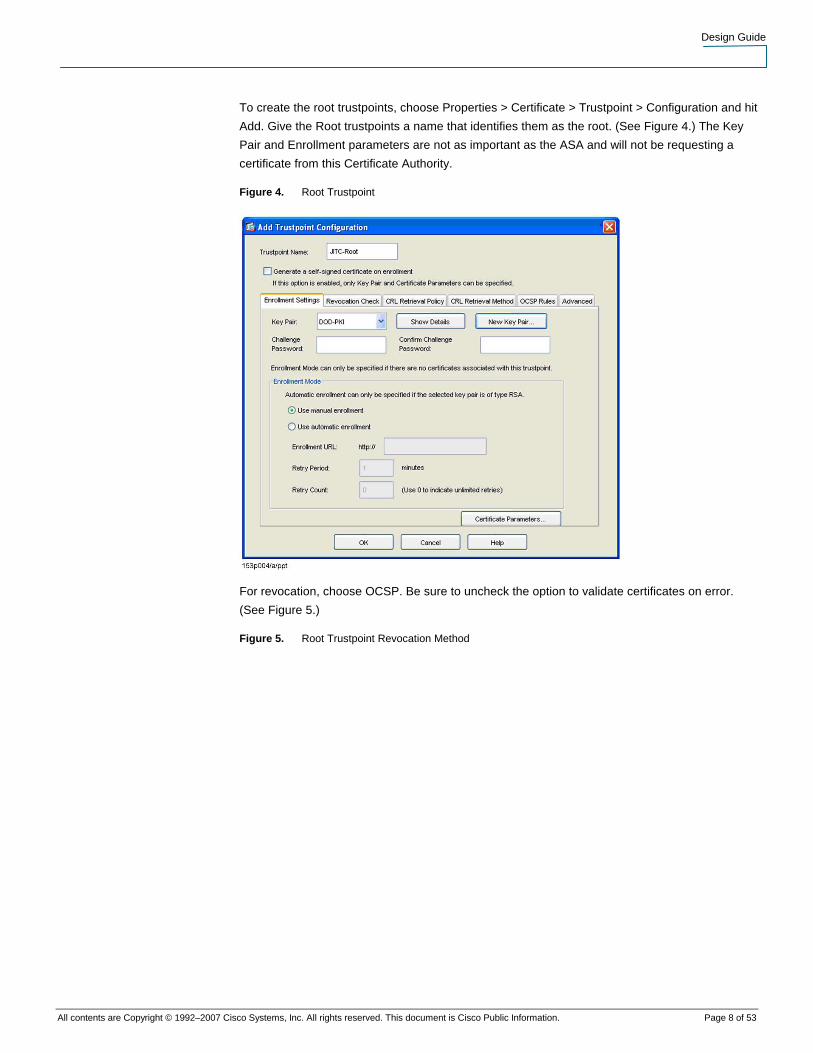
To create the root trustpoints, choose Properties > Certificate > Trustpoint > Configuration and hit
Add. Give the Root trustpoints a name that identifies them as the root. (See Figure 4.) The Key
Pair and Enrollment parameters are not as important as the ASA and will not be requesting a
certificate from this Certificate Authority.
Figure 4. Root Trustpoint
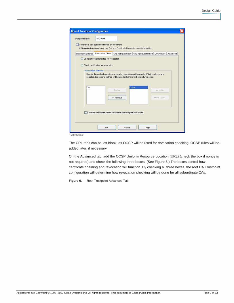
For revocation, choose OCSP. Be sure to uncheck the option to validate certificates on error.
(See Figure 5.)
Figure 5. Root Trustpoint Revocation Method
Design Guide
All contents are Copyright © 1992–2007 Cisco Systems, Inc. All rights reserved. This document is Cisco Public Information. Page 9 of 53
The CRL tabs can be left blank, as OCSP will be used for revocation checking. OCSP rules will be
added later, if necessary.
On the Advanced tab, add the OCSP Uniform Resource Location (URL) (check the box if nonce is
not required) and check the following three boxes. (See Figure 6.) The boxes control how
certificate chaining and revocation will function. By checking all three boxes, the root CA Trustpoint
configuration will determine how revocation checking will be done for all subordinate CAs.
Figure 6. Root Trustpoint Advanced Tab

Design Guide
All contents are Copyright © 1992–2007 Cisco Systems, Inc. All rights reserved. This document is Cisco Public Information. Page 10 of 53
The next trustpoint to configure is the trustpoint that the ASA will be enrolling. For the subordinate
CA Trustpoint, be sure to include a Rivest, Shamir, and Adelman (RSA) key pair, choose manual
enrollment, and modify the Certificate Parameters by clicking the Certificate Parameters button
(Figure 7).
Figure 7. Subordinate CA Enrollment Settings
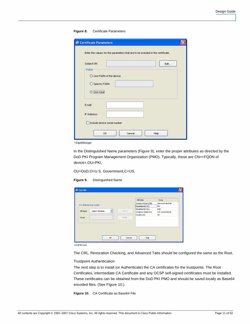
For enrollment CA, choose Use none for FQDN, and leave the email address, IP address, and
serial number fields blank (Figure 8). Click the Edit button to alter the Subject Distinguished Name
field.
Design Guide
All contents are Copyright © 1992–2007 Cisco Systems, Inc. All rights reserved. This document is Cisco Public Information. Page 11 of 53
Figure 8. Certificate Parameters
In the Distinguished Name parameters (Figure 9), enter the proper attributes as directed by the
DoD PKI Program Management Organization (PMO). Typically, these are CN=<FQDN of
device>,OU=PKI,
OU=DoD,O=U.S. Government,C=US.
Figure 9. Distinguished Name
The CRL, Revocation Checking, and Advanced Tabs should be configured the same as the Root.
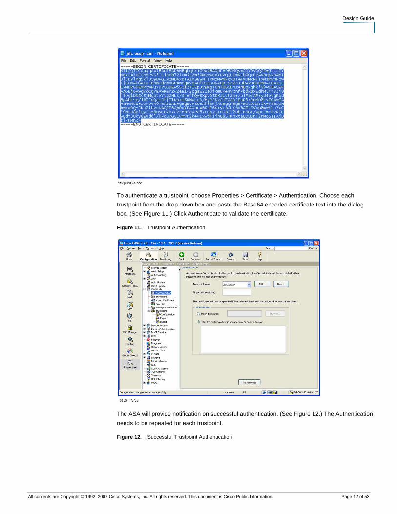
Trustpoint Authentication
The next step is to install (or Authenticate) the CA certificates for the trustpoints. The Root
Certificates, intermediate CA Certificate and any OCSP self-signed certificates must be installed.
These certificates can be obtained from the DoD PKI PMO and should be saved locally as Base64
encoded files. (See Figure 10.)
Figure 10. CA Certificate as Base64 File
Design Guide
All contents are Copyright © 1992–2007 Cisco Systems, Inc. All rights reserved. This document is Cisco Public Information. Page 12 of 53
To authenticate a trustpoint, choose Properties > Certificate > Authentication. Choose each
trustpoint from the drop down box and paste the Base64 encoded certificate text into the dialog
box. (See Figure 11.) Click Authenticate to validate the certificate.
Figure 11. Trustpoint Authentication
The ASA will provide notification on successful authentication. (See Figure 12.) The Authentication
needs to be repeated for each trustpoint.
Figure 12. Successful Trustpoint Authentication

Design Guide
All contents are Copyright © 1992–2007 Cisco Systems, Inc. All rights reserved. This document is Cisco Public Information. Page 13 of 53
Certificate Enrollment
In order to support two-way certificate authentication, the ASA will need a certificate installed. To
obtain a certificate, the ASA must enroll with a subordinate CA. (See Figure 13.) The process for
obtaining device certificates can be obtained from the DoD PKI PMO. When requesting a
certificate, a request for an SSL server certificate is acceptable for use on the ASA.
Figure 13. Certificate Enrollment
To request a certificate, a PKCS10 request must be made by the ASA. Choose Properties >
Certificate > Enrollment, select the correct CA, and click Enroll to generate an enrollment request.
Copy the text from the enrollment request window (Figure 14) and paste it into the CA’s Certificate
Request Form (Figure 15).
Figure 14. Certificate Enrollment Request

Design Guide
All contents are Copyright © 1992–2007 Cisco Systems, Inc. All rights reserved. This document is Cisco Public Information. Page 14 of 53
Figure 15. Certificate Request Form
Once the certificate request is submitted, follow the documented process to ensure that the
certificate is generated. Once the certificate is generated, it must be retrieved from the CA and
installed on the ASA.

Design Guide
All contents are Copyright © 1992–2007 Cisco Systems, Inc. All rights reserved. This document is Cisco Public Information. Page 15 of 53
Copy the Base64 encoded certificate from the CA Web page (Figure 16) to the ASA’s Import
Certificate page (Figure 17). Click Import to import the certificate into the ASA.
Figure 16. Certificate Retrieval
Figure 17. Import Certificate

Design Guide
All contents are Copyright © 1992–2007 Cisco Systems, Inc. All rights reserved. This document is Cisco Public Information. Page 16 of 53
OCSP Configuration
To support the DoD implementation of OCSP, it is necessary to create a different Trustpoint for the
OCSP responders and to configure OCSP rules under the DoD Root Trustpoint. The OCSP
Responder Trustpoint allows the DoD PKI certificates to be validated against the DoD’s self-signed
OCSP responders. The OCSP rules instruct the ASA to search in a nonstandard location for the
OCSP responder.
Group Matching
To choose the correct certificates for the OCSP overrides, certificate group matching rules must be
created. To create the rule, first browse to VPN > IKE > Certificate Group Matching > Rules. Click
Add and choose a name as in Figure 18. There is no need to select a Group under the Mapped to
Group dialog.
Figure 18. Certificate Matching Rule Name

Design Guide
All contents are Copyright © 1992–2007 Cisco Systems, Inc. All rights reserved. This document is Cisco Public Information. Page 17 of 53
Next, click on the newly highlighted Add Button to define the Rule. Create the rule so that it reads
Field = “Subject,” Component = “Whole Field,” Operator = “Contains” and Value = “DOD” as in
Figure 19.
Figure 19. Certificate Matching Rule Definition
Trustpoint Configuration
Create a Trustpoint for the OCSP responder’s certificate (Figure 20). Use the same process used
earlier for creating a new Trustpoint. Be sure to choose no revocation checking, as the self-signed
certificate will not provide a CRL for itself (Figure 21).
Figure 20. OCSP Trustpoint

Design Guide
All contents are Copyright © 1992–2007 Cisco Systems, Inc. All rights reserved. This document is Cisco Public Information. Page 18 of 53
Figure 21. OCSP Trustpoint Revocation Checking
After the OCSP Responder’s certificate is installed, return to the DoD Root Trustpoint configuration
screens and add a new OCSP Rule (Figure 22). The Rule will need to match the DoD PKI

Design Guide
All contents are Copyright © 1992–2007 Cisco Systems, Inc. All rights reserved. This document is Cisco Public Information. Page 19 of 53
certificates (using the Certificate Map created earlier) and point to the OCSP URL for OCSP
response checking. Be sure to use the OCSP Trustpoint as the Trustpoint for the OCSP Rule
(Figure 23). Also, be sure to repeat the OCSP configuration for both DoD Root Trustpoints.
Figure 22. New OSCP Rule
Figure 23. OCSP Rules
AAA Configuration
AAA consists of Authentication, Authorization, and Accounting. Since the Authentication is being
done with PKI certificates, only the Authorization and Accounting require additional configurations.

Design Guide
All contents are Copyright © 1992–2007 Cisco Systems, Inc. All rights reserved. This document is Cisco Public Information. Page 20 of 53
This implementation guide does not include accounting configuration. For Authorization, we will
use the LDAP protocol to connect to the Active Directory to check the UPN.
LDAP Groups
The first step is to choose the Configuration Tab in ASDM, and choose Properties > AAA Setup
(see Figure 24) and add a new AAA Server Group. Choose LDAP, accept the defaults, and hit OK
to add the LDAP Group (see Figure 25). Once the LDAP group is configured, add a new server
entry for each Domain Controller (DC) that should be queried. It is advisable to add multiple DCs in
case one is not available.
Figure 24. AAA Server Groups
Figure 25. LDAP Server Group

Design Guide
All contents are Copyright © 1992–2007 Cisco Systems, Inc. All rights reserved. This document is Cisco Public Information. Page 21 of 53
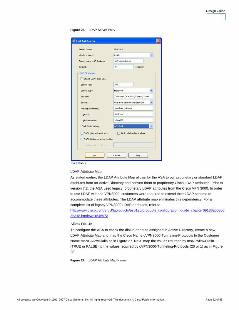
The LDAP server settings include the IP address of the server, TCP port, server types, the
BaseDN for searching, and other fields. These fields will correspond to the fields in Active
Directory. To determine the best entries for the field, use an LDAP browser to browse Active
Directory as shown in Figure 3. The descriptions for these fields are outlined in Table 1.
Table 1. LDAP Fields
Field Value Description
Interface Interface Name Indicates the ASA interface that should be used to contact the server.
Server Name or IP Address DNS or IP Address
Address of an AD Server.
Timeout Seconds Amount of time for the ASA to wait for a response from the server.
Server Port TCP Port TCP port used to connect to server.
Server Type Microsoft Indicates that this is an MS LDAP server.
BaseDN LDAP DN This is the search base for the LDAP query. The ASA will use this as the base of the search for the attribute. This is where all of the users should be located. If users are in multiple AD OUs, then this should be the top-level OU. Use an LDAP browser to determine the best entry.
Scope Number of Levels to Search
This setting indicates whether the ASA should search one level below the BaseDN or scan the whole tree below the BaseDN. If all users are in the same AD OU, then one level should be chosen. If users are in multiple OUs, then choose subtree. Searching one level will be much quicker than searching the subtree.
LoginDN User Name for ASA to Use to Scan LDAP
This user ID must be defined in AD with a username and password. It must have rights to read all OUs in the AD that need to be scanned for user data. It should be denied login access, etc., as necessary to ensure it is not used maliciously. Also, be sure to use the entire LDAP Distinguished Name in this field instead of the AD UPN or SAN.
Login Password Password for ASA AD Account
Password used to access AD. It is currently stored using reversible encryption. This is the primary reason that the user ID for ASA should have minimal rights in the AD.
Attribute Map Map Name The LDAP Attribute Map function allows proprietary Cisco LDAP values to be mapped to Microsoft values in AD (or standard LDAP values). It is a powerful feature that will allow the use of AD to define Group Policy and access rights to ASA VPN users. It is discussed in the next section.
Security Checkboxes Various Security Parameters
Check with the AD administrators to determine which security settings are required to securely access the AD via LDAP.
The AAA Server Entry for the Active Directory LDAP access is illustrated in Figure 26.
Design Guide
All contents are Copyright © 1992–2007 Cisco Systems, Inc. All rights reserved. This document is Cisco Public Information. Page 22 of 53
Figure 26. LDAP Server Entry
LDAP Attribute Map
As stated earlier, the LDAP Attribute Map allows for the ASA to pull proprietary or standard LDAP
attributes from an Active Directory and convert them to proprietary Cisco LDAP attributes. Prior to
version 7.2, the ASA used legacy, proprietary LDAP attributes from the Cisco VPN 3000. In order
to use LDAP with the VPN3000, customers were required to extend their LDAP schema to
accommodate these attributes. The LDAP attribute map eliminates this dependency. For a
complete list of legacy VPN3000 LDAP attributes, refer to
http://www.cisco.com/en/US/products/ps6120/products_configuration_guide_chapter09186a00806
3b318.html#wp1546973.
Allow Dial-In
To configure the ASA to check the dial-in attribute assigned in Active Directory, create a new
LDAP Attribute Map and map the Cisco Name cVPN3000-Tunneling-Protocols to the Customer
Name msNPAllowDialin as in Figure 27. Next, map the values returned by msNPAllowDialin
(TRUE or FALSE) to the values required by cVPN3000-Tunneling-Protocols (20 or 1) as in Figure
28.
Figure 27. LDAP Attribute Map Name

Design Guide
All contents are Copyright © 1992–2007 Cisco Systems, Inc. All rights reserved. This document is Cisco Public Information. Page 23 of 53
Figure 28. LDAP Attribute Map Values
Access to the ASA VPN will now be controlled by this AD parameter and is summarized in Table
2.
Table 2. Dial-In Values
Dial-In Dialog msNPAllowDialin Value cVPN3000-Tunneling-Protocol Value
Allow Access True 20
Deny Access False 1
Control Access Through RAS Policy N/A (not sent) Set by ASA Group Policy
The value assigned to cVPN3000-Tunneling-Protocol indicates which protocols can be used.
Setting this value to 20 allows all protocols (IPSec, WebVPN, L2TP/IPSec). For a complete
description of these values, check
http://www.cisco.com/en/US/products/ps6120/products_configuration_guide_chapter09186a00806
3b318.html#wp1546973.

Design Guide
All contents are Copyright © 1992–2007 Cisco Systems, Inc. All rights reserved. This document is Cisco Public Information. Page 24 of 53
External Group Policies
Any values in Active Directory can be remapped via LDAP Attribute Mapping. ASA External Group
Policies can also be defined in AD and mapped to ASA settings. The ASA obtains the value for the
External Group that should be used for the user from the user record. ASA then performs a
separate LDAP query for a Username corresponding to the External Group. This requires
configuring a User ID in Active Directory that is used as a template for the External Group settings.
Note: These accounts should be configured in Active Directory so that a rogue user will not
have access to these accounts.
The advantage is that changes to the External Group policy only need to happen once. Internal
Groups can also be defined in the ASA and individual values set in AD for each user to override
the Internal Group settings (as shown in the Allow Dial-In example). With External Groups, all
changes can be made in AD and the user record only needs to reflect which template user to
query for the settings.
In this example, we are defining an External Group Policy and mapping it to settings in the Active
Directory. The chosen AD fields are not mandatory. Any fields could be used to define the values.
The settings pulled from AD are the IPSec Banner (cVPN3000-IPSec-Banner1) and the Idle
Timeout (cVPN3000-IETF-RADIUS-Session-Timeout).
First, create a template user in AD that will contain the settings (see Figure 29). We chose the
UPN VPNUserGroup and decided to use Description for the IPSec Banner and Office for the Idle
Timer.
Figure 29. External Group Template User
Any other AD values (telephone number, email, etc.) could also be used on the Template User.
They do not have to correspond in any way to the values normally used in the AD environment. To
determine what the values are, use an LDAP browser to scan the Template User.

Design Guide
All contents are Copyright © 1992–2007 Cisco Systems, Inc. All rights reserved. This document is Cisco Public Information. Page 25 of 53
Next, alter the individual user records to indicate which External Group Policy will be used. This will
need to match exactly the Template User UPN. We chose Department, as it seemed like a good
indicator of which group the user may belong to (see Figure 30).
Figure 30. User Record Referencing Template User
The ASA configuration involves creating an LDAP Attribute Map to map the values. The LDAP
values that need to be mapped are illustrated in Figure 31. No Map Values need to be assigned,
as the user will use the values as they appear in the Active Directory. Browsing the LDAP structure
will reveal what each attribute is called in AD. The list of Cisco proprietary attribute names can be
found at
http://www.cisco.com/en/US/products/ps6120/products_configuration_guide_chapter09186a00806
3b318.html#wp1546973.
Figure 31. External Group Policy LDAP Attribute Map

Design Guide
All contents are Copyright © 1992–2007 Cisco Systems, Inc. All rights reserved. This document is Cisco Public Information. Page 26 of 53
Assign the LDAP Attribute Map to the LDAP entry shown in Figure 26. Any entries not defined in
the Active Directory will be pulled from the Default Group Policy.
Remote Access VPN Configuration
ASA Configuration
Tunnel Group
The parameters for Remote Access Connections are configured in Tunnel Groups. To create a
Tunnel Group to support CAC authentication, choose VPN > General > Tunnel Group and add a
new Tunnel Group. The Basic settings can use the Default Group Policy or another Group Policy
as needed.
On the General > Advanced Tab, choose anything for authentication (see Figure 32). This controls
which AAA group will be used for Extended Authentication (Xauth). This configuration cannot use
Xauth, so the settings do not matter.
Figure 32. Tunnel Group Authentication
For Authorization, choose the Active Directory LDAP Group and specify UPN as the Primary DN
Field as shown in Figure 33.
Note: UPN is not supported in this release of ASDM but is available at the command line. See
Appendix A for the command line syntax.
Figure 33. Tunnel Group Authorization

Design Guide
All contents are Copyright © 1992–2007 Cisco Systems, Inc. All rights reserved. This document is Cisco Public Information. Page 27 of 53
Next, browse to the IPSec tab and choose the Trustpoint name that contains the ASA certificate
(see Figure 34). Choose none from the Authentication mode drop-down list to disable Xauth. IKE
Peer ID Validation must be required as that enables certificate authentication. The ASA must be
configured to send the certificate chain, or the VPN Client may fail the connection. The remaining
parameters are optional.
Figure 34. Tunnel Group Authorization IPSec Tab

Design Guide
All contents are Copyright © 1992–2007 Cisco Systems, Inc. All rights reserved. This document is Cisco Public Information. Page 28 of 53
Group Policies
Minimal changes need to be made to the Default Group Policy. (See Figure 35.) The Default
Group Policy will apply to all Tunnel Groups and subsequent Group Policies. The values
configured can be overridden in the individual polices. Examples of items that may be desirable to
enter are Domain Name Servers (DNS), Split Tunneling Polices, Address Pools, etc. (See Figure
36.)
Figure 35. Default Group Policy General Settings
Figure 36. Default Group Policy Client Tab
Design Guide
All contents are Copyright © 1992–2007 Cisco Systems, Inc. All rights reserved. This document is Cisco Public Information. Page 29 of 53
Internet Key Exchange
Next, define the Internet Key Exchange (IKE) settings.
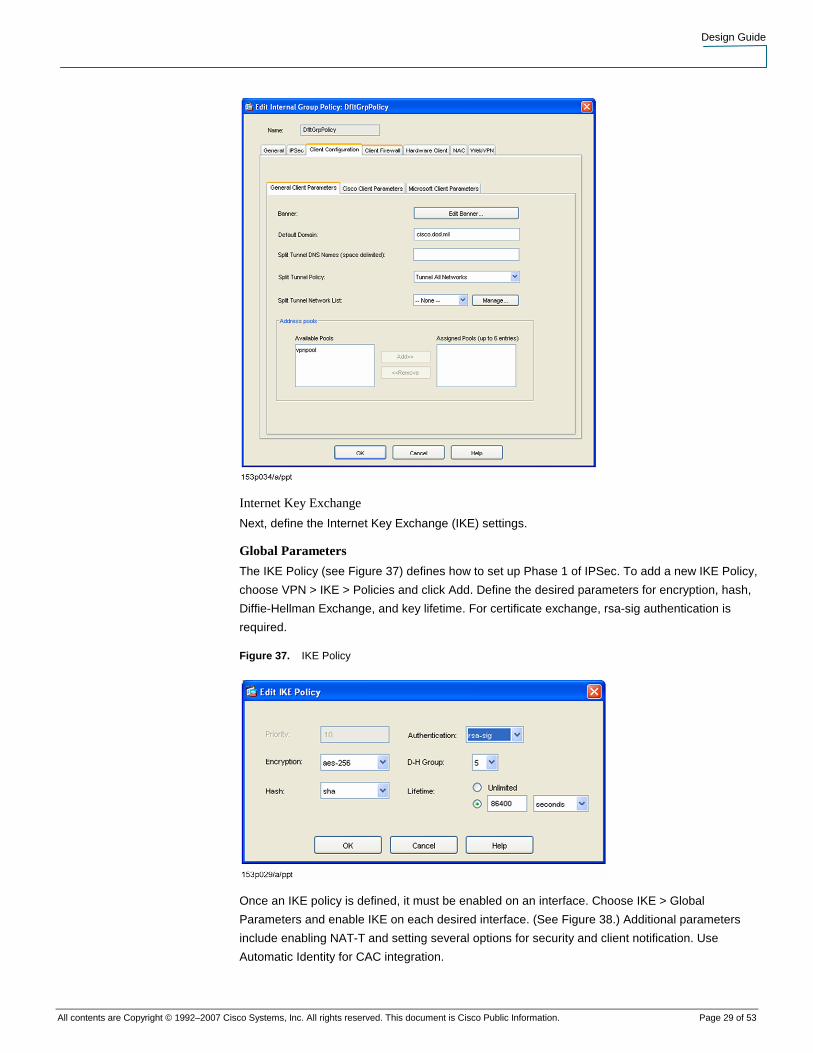
Global Parameters
The IKE Policy (see Figure 37) defines how to set up Phase 1 of IPSec. To add a new IKE Policy,
choose VPN > IKE > Policies and click Add. Define the desired parameters for encryption, hash,
Diffie-Hellman Exchange, and key lifetime. For certificate exchange, rsa-sig authentication is
required.
Figure 37. IKE Policy
Once an IKE policy is defined, it must be enabled on an interface. Choose IKE > Global
Parameters and enable IKE on each desired interface. (See Figure 38.) Additional parameters
include enabling NAT-T and setting several options for security and client notification. Use
Automatic Identity for CAC integration.

Design Guide
All contents are Copyright © 1992–2007 Cisco Systems, Inc. All rights reserved. This document is Cisco Public Information. Page 30 of 53
Figure 38. Globally Enabling Internet Key Exchange
Certificate Group Matching
When a certificate is presented, the ASA must know which Tunnel Group to associate with the
certificate. By default, the ASA will try to match any field in the OU Field in the Certificate with a
Tunnel Group. For best results, this can be overridden by browsing to IKE > Certificate Group
Matching > Policy. Uncheck all of the options except the Default. From the drop down choose the
Tunnel Group created earlier (see Figure 39).
Figure 39. Tunnel Group Association

Design Guide
All contents are Copyright © 1992–2007 Cisco Systems, Inc. All rights reserved. This document is Cisco Public Information. Page 31 of 53
IPSec Configuration
IPSec rules define which traffic should be encrypted. To define “interesting” traffic for IPSec, create
an IPSec rule by browsing to VPN > IPSec > IPSec Rules and hitting Add. Choose the Interface,
users will be connecting. For remote access, the Policy Type should be dynamic. Priority is
configurable. If multiple IPSec rules exist, they are processed based on priority. If this is the first
IPSec Rule, it is desirable to choose a priority higher than 1 so that other IPSec rules can be
inserted later. (See Figure 40.)
Next, choose one or more Transform Sets to be added. The priority of the transport set can be
moved up or down as needed. Additional transform sets can also be defined, but the default sets
are typically satisfactory for most installations. Peer Settings should be blank for Remote Access.
Perfect Forward Secrecy provides higher security for the IPSec tunnel but is very costly in
performance.
Figure 40. IPSec Rule Creation
The Advanced tab contains options for Security Association Lifetime, NAT-T, and Reverse Route
Injection, which are optional components.
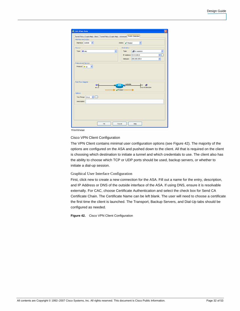
The Traffic Selection tab defines that the traffic should be encrypted by the tunnel and is required.
(See Figure 41.)
Figure 41. IPSec Traffic Assignment
Design Guide
All contents are Copyright © 1992–2007 Cisco Systems, Inc. All rights reserved. This document is Cisco Public Information. Page 32 of 53
Cisco VPN Client Configuration
The VPN Client contains minimal user configuration options (see Figure 42). The majority of the
options are configured on the ASA and pushed down to the client. All that is required on the client
is choosing which destination to initiate a tunnel and which credentials to use. The client also has
the ability to choose which TCP or UDP ports should be used, backup servers, or whether to
initiate a dial-up session.
Graphical User Interface Configuration
First, click new to create a new connection for the ASA. Fill out a name for the entry, description,
and IP Address or DNS of the outside interface of the ASA. If using DNS, ensure it is resolvable
externally. For CAC, choose Certificate Authentication and select the check box for Send CA
Certificate Chain. The Certificate Name can be left blank. The user will need to choose a certificate
the first time the client is launched. The Transport, Backup Servers, and Dial-Up tabs should be
configured as needed.
Figure 42. Cisco VPN Client Configuration

Design Guide
All contents are Copyright © 1992–2007 Cisco Systems, Inc. All rights reserved. This document is Cisco Public Information. Page 33 of 53
When CACs are inserted in a reader, the Middleware presents the certificates to the system via
the Microsoft CAPI. The VPN client queries CAPI when launched and presents all of the
certificates available in the User Store. The Certificates Tab will display all of the certificates
available to the user (Figure 43).
Figure 43. Cisco VPN Client Certificate View
Using Profile Files
All of the information for the connection is stored in the \Program Files\Cisco Systems\VPN
Client\Profiles directory on the workstation. Each connection profile is stored in a .pcf text file with
various elements. Template profiles can be created and deployed to pre-configure workstations.
Details on deployment options for the VPN Client can be found at
http://www.cisco.com/en/US/products/sw/secursw/ps2308/products_administration_guide_book09
186a00802d5d97.html.
One limitation of the Cisco VPN Client is that it does not display the Friendly Name field on the
certificate. This problem can prevent the user from knowing which of the three certificates to
choose. Fortunately, there are a couple of options in the profile that allow for automatic selection of
the proper certificate. The fields are CertMatchKU and CertMatchDN. By setting them to the values

Design Guide
All contents are Copyright © 1992–2007 Cisco Systems, Inc. All rights reserved. This document is Cisco Public Information. Page 34 of 53
shown in the following configuration, the VPN Client will choose the signature certificate when
sending authentication information to the ASA. The user does not need to select a certificate at
any point during authentication. For best results, the .PCF files should be pre-installed on
workstations before the user attempts to log on. There is also a field available called
CertMatchEKU, but use of this field has provided inconsistent results.
[main]
Description=CAC Connection to ASA
Host=192.168.1.17
AuthType=3
!Username=
!UserPassword=
!CertSubjectName=
!CertSerialHash=
!CertName=
CertMatchKU=7,8
CertMatchDN=issuer-cn*"EMAIL"
SendCertChain=1
CertStore=2"
WebVPN Configuration
Most of the building blocks used for Remote Access VPN will also be used for WebVPN
connections. This section will detail the basics of configuring WebVPN to support the CAC. Further
configuration information for WebVPN can be found at
http://www.cisco.com/en/US/products/ps6120/products_configuration_guide_chapter09186a00806
3b194.html.
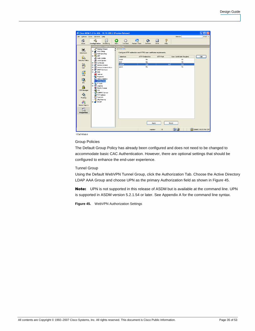
Enable SSL User Certificate Exchange
To enable WebVPN CAC integration, the outside (or VPN facing) interface needs to require
certificates for user Hypertext Transfer Protocol/Hypertext Transfer Protocol Secure
(HTTP/HTTPS) connections. To enable this requirement, choose Properties > HTTP/HTTPS and
edit the proper interfaces as in Figure 44.
Figure 44. Required Certificates for HTTPS
Design Guide
All contents are Copyright © 1992–2007 Cisco Systems, Inc. All rights reserved. This document is Cisco Public Information. Page 35 of 53
Group Policies
The Default Group Policy has already been configured and does not need to be changed to
accommodate basic CAC Authentication. However, there are optional settings that should be
configured to enhance the end-user experience.
Tunnel Group
Using the Default WebVPN Tunnel Group, click the Authorization Tab. Choose the Active Directory
LDAP AAA Group and choose UPN as the primary Authorization field as shown in Figure 45.
Note: UPN is not supported in this release of ASDM but is available at the command line. UPN
is supported in ASDM version 5.2.1.54 or later. See Appendix A for the command line syntax.
Figure 45. WebVPN Authorization Settings

Design Guide
All contents are Copyright © 1992–2007 Cisco Systems, Inc. All rights reserved. This document is Cisco Public Information. Page 36 of 53
Next, browse to the WebVPN > Basic tab and choose Certificate Authentication (see Figure 46).
Figure 46. WebVPN Certificate Authentication

Design Guide
All contents are Copyright © 1992–2007 Cisco Systems, Inc. All rights reserved. This document is Cisco Public Information. Page 37 of 53
Optional Components
Additional WebVPN components that can be added are the Cisco Secure Desktop and the SSL
VPN Client. Details on configuring these components can be found at
http://www.cisco.com/en/US/products/ps6120/products_configuration_guide_chapter09186a00806
3b194.html.

Design Guide
All contents are Copyright © 1992–2007 Cisco Systems, Inc. All rights reserved. This document is Cisco Public Information. Page 38 of 53
Acronyms
AD Active Directory
API Application Programming Interface
ASA Adaptive Security Appliance
ASDM Adaptive Security Device Manager
CA Certification Authority
CAC Common Access Card
CAPI Certificate Application Programming Interface
CRL Certificate Revocation List
DC Domain Controller
DN Distinguished Name
DoD Department of Defense
EKU Enhanced Key Usage
GUI Graphical User Interface
IKE Internet Key Exchange
IP Internet Protocol
IPSec Internet Protocol Security
ISO International Standards Organization
KU Key Usage
L2TP Layer 2 Tunneling Protocol
LDAP Lightweight Directory Access Protocol
OCSP Online Certificate Status Protocol
OID Object Identifier
OS Operating System
OU Organizational Unit
PIN Personal Identification Number
PKI Public Key Infrastructure
PMO Program Management Organization
PN Principal Name
RADIUS Remote Authentication Dial-In User Servers
RSA Rivest, Shamir, and Adelman
SAN Subject Alternative Name

Design Guide
All contents are Copyright © 1992–2007 Cisco Systems, Inc. All rights reserved. This document is Cisco Public Information. Page 39 of 53
SSH Secure Shell
SSL Secure Socket Layer
TCP Transmission Control Protocol
UPN User Principal Name
URL Uniform Resource Location
VPN Virtual Private Network

Design Guide
All contents are Copyright © 1992–2007 Cisco Systems, Inc. All rights reserved. This document is Cisco Public Information. Page 40 of 53
Appendix A – ASA CLI Configuration
ASA Version 7.2(1)0
!
hostname asa
domain-name cisco.dod.mil
enable password 2KFQnbNIdI.2KYOU encrypted
names
name 10.10.100.2 ad1.cisco.dod.mil description Domain Controller
dns-guard
!
interface GigabitEthernet0/0
nameif inside
security-level 100
ip address 10.10.200.2 255.255.255.0
!
interface GigabitEthernet0/1
nameif dmz
security-level 75
ip address 192.168.80.1 255.255.255.0
!
interface GigabitEthernet0/2
nameif guest
security-level 25
ip address 192.168.90.1 255.255.255.0
!
interface GigabitEthernet0/3
nameif outside
security-level 0
ip address dhcp setroute
!
interface Management0/0
shutdown

Design Guide
All contents are Copyright © 1992–2007 Cisco Systems, Inc. All rights reserved. This document is Cisco Public Information. Page 41 of 53
no nameif
no security-level
no ip address
!
passwd 2KFQnbNIdI.2KYOU encrypted
boot system disk0:/cdisk.chad2
ftp mode passive
clock timezone CST -6
clock summer-time CDT recurring
dns domain-lookup inside
dns domain-lookup outside
dns server-group DefaultDNS
name-server ad1.cisco.dod.mil
domain-name cisco.dod.mil
access-list inside_nat0_outbound extended permit ip 10.10.0.0 255.255.0.0 192.168.80.0
255.255.255.0
access-list inside_nat0_outbound extended permit ip 10.10.0.0 255.255.0.0 10.10.200.0
255.255.255.0
access-list inside_nat0_outbound extended permit ip any 10.10.200.48 255.255.255.240
access-list dmz_access_in extended permit udp 192.168.80.0 255.255.255.0 host
ad1.cisco.dod.mil eq domain
access-list dmz_access_in extended deny ip any 10.10.0.0 255.255.0.0
access-list dmz_access_in extended permit ip 192.168.80.0 255.255.255.0 any
access-list outside_cryptomap_65535.10 extended permit ip any any
access-list dmz_cryptomap extended permit ip any 10.10.200.48 255.255.255.240
pager lines 24
logging enable
logging monitor debugging
logging asdm informational
mtu inside 1500
mtu dmz 1500
mtu guest 1500
mtu outside 1500

Design Guide
All contents are Copyright © 1992–2007 Cisco Systems, Inc. All rights reserved. This document is Cisco Public Information. Page 42 of 53
ip local pool vpnpool 10.10.200.50-10.10.200.60 mask 255.255.255.0
no failover
asdm image disk0:/asdm521.bin
no asdm history enable
arp timeout 14400
nat-control
global (outside) 1 interface
nat (inside) 0 access-list inside_nat0_outbound
nat (inside) 1 10.10.0.0 255.255.0.0 dns
nat (dmz) 1 192.168.80.0 255.255.255.0 dns
access-group dmz_access_in in interface dmz
route inside 10.10.0.0 255.255.0.0 10.10.200.1 1
timeout xlate 3:00:00
timeout conn 1:00:00 half-closed 0:10:00 udp 0:02:00 icmp 0:00:02
timeout sunrpc 0:10:00 h323 0:05:00 h225 1:00:00 mgcp 0:05:00 mgcp-pat 0:05:00
timeout sip 0:30:00 sip_media 0:02:00 sip-invite 0:03:00 sip-disconnect 0:02:00
timeout uauth 0:05:00 absolute
ldap attribute-map AD-LDAP
map-name msNPAllowDialin cVPN3000-Tunneling-Protocols
map-value msNPAllowDialin FALSE 1
map-value msNPAllowDialin TRUE 20
aaa-server ACS protocol radius
aaa-server ACS host 10.10.100.3
key cisco
aaa-server AD protocol kerberos
aaa-server AD host ad1.cisco.dod.mil
kerberos-realm CISCO.DOD.MIL
aaa-server AD-LDAP protocol ldap
aaa-server AD-LDAP host ad1.cisco.dod.mil
ldap-base-dn CN=Users,DC=cisco,DC=dod,DC=mil
ldap-scope onelevel
ldap-naming-attribute userPrincipalName
Design Guide
All contents are Copyright © 1992–2007 Cisco Systems, Inc. All rights reserved. This document is Cisco Public Information. Page 43 of 53
ldap-login-password ci$co123
ldap-login-dn cn=ACSUser,cn=Users,dc=cisco,dc=dod,dc=mil
server-type microsoft
ldap-attribute-map AD-LDAP
aaa-server IAS protocol radius
aaa-server IAS host 10.10.100.6
key cisco
aaa-server AD-LDAP-2 protocol ldap
aaa-server AD-LDAP-2 host ad1.cisco.dod.mil
ldap-base-dn cn=Users,dc=cisco,dc=dod,dc=mil
ldap-scope onelevel
ldap-naming-attribute userPrincipalName
ldap-login-password ci$co123
ldap-login-dn cn=ACSUser,cn=Users,dc=cisco,dc=dod,dc=mil
server-type microsoft
ldap-attribute-map AD-LDAP
group-policy DfltGrpPolicy attributes
banner value Use of this DoD computer system, authorized or unauthorized, constitutes consent to
monitoring of this system. Unauthorized use may subject you to criminal prosecution. Evidence of
unauthorized use collected during monitoring may be used for administrative, criminal, or other
adverse action. Use of this system constitutes consent to monitoring for these purposes.
wins-server none
dns-server value 10.10.100.2
dhcp-network-scope 10.10.200.0
vpn-access-hours none
vpn-simultaneous-logins 3
vpn-idle-timeout 30
vpn-session-timeout none
vpn-filter none
vpn-tunnel-protocol IPSec l2tp-ipsec webvpn
password-storage disable
ip-comp disable
re-xauth disable

Design Guide
All contents are Copyright © 1992–2007 Cisco Systems, Inc. All rights reserved. This document is Cisco Public Information. Page 44 of 53
group-lock none
pfs disable
ipsec-udp enable
ipsec-udp-port 10000
split-tunnel-policy tunnelall
split-tunnel-network-list none
default-domain value cisco.dod.mil
split-dns none
intercept-dhcp 255.255.255.255 disable
secure-unit-authentication disable
user-authentication disable
user-authentication-idle-timeout 30
ip-phone-bypass disable
leap-bypass disable
nem disable
backup-servers keep-client-config
msie-proxy server none
msie-proxy method no-modify
msie-proxy except-list none
msie-proxy local-bypass disable
nac disable
nac-sq-period 300
nac-reval-period 36000
nac-default-acl none
address-pools none
client-firewall none
client-access-rule none
webvpn
functions url-entry
html-content-filter none
homepage none
keep-alive-ignore 4
Design Guide
All contents are Copyright © 1992–2007 Cisco Systems, Inc. All rights reserved. This document is Cisco Public Information. Page 45 of 53
http-comp gzip
filter none
url-list none
customization value DfltCustomization
port-forward none
port-forward-name value Application Access
sso-server none
deny-message value Login was successful, but because certain criteria have not been met or due
to some specific group policy, you do not have permission to use any of the VPN features. Contact
your IT administrator for more information
svc none
svc keep-installer installed
svc keepalive none
svc rekey time none
svc rekey method none
svc dpd-interval client none
svc dpd-interval gateway none
svc compression deflate
username WOOLWINE.CHAD.1.1160082018 nopassword
http server enable
http 10.10.100.0 255.255.255.0 inside
http authentication-certificate outside
http redirect outside 80
no snmp-server location
no snmp-server contact
snmp-server enable traps snmp authentication linkup linkdown coldstart
crypto ipsec transform-set ESP-AES-256-SHA esp-aes-256 esp-sha-hmac
crypto dynamic-map outside_dyn_map 10 match address outside_cryptomap_65535.10
crypto dynamic-map outside_dyn_map 10 set transform-set ESP-AES-256-SHA
crypto dynamic-map outside_dyn_map 10 set nat-t-disable
crypto dynamic-map dmz_dyn_map 20 set transform-set ESP-AES-256-SHA
crypto map outside_map 65535 ipsec-isakmp dynamic outside_dyn_map
Design Guide
All contents are Copyright © 1992–2007 Cisco Systems, Inc. All rights reserved. This document is Cisco Public Information. Page 46 of 53
crypto map outside_map interface outside
crypto ca trustpoint JITC-OCSP
enrollment terminal
crl configure
crypto ca trustpoint JITC-CA7
revocation-check ocsp none
keypair DOD-PKI
ocsp disable-nonce
ocsp url http://ocsp.nsn0.rcvs.nit.disa.mil
crl configure
crypto ca trustpoint JITC-Root
revocation-check ocsp none
enrollment terminal
keypair DOD-PKI
ocsp disable-nonce
ocsp url http://ocsp.nsn0.rcvs.nit.disa.mil
match certificate DOD override ocsp trustpoint JITC-OCSP 10 url http://ocsp.nsn0.rcvs.nit.disa.mil
crl configure
no enforcenextupdate
no protocol http
no protocol ldap
no protocol scep
crypto ca certificate map DOD 10
subject-name co dod
crypto ca certificate chain JITC-OCSP
certificate ca 00
30820241 308201aa a0030201 02020100 300d0609 2a864886 f70d0101 05050030
4e310b30 09060355 04061302 75733118 30160603 55040a13 0f552e53 2e20476f
7665726e 6d656e74 310c300a 06035504 0b130344 6f443117 30150603 55040313
0e524356 53204a49 5443204f 43535030 1e170d30 35303132 35323133 3330345a
170d3038 30333135 32313333 30345a30 4e310b30 09060355 04061302 75733118
30160603 55040a13 0f552e53 2e20476f 7665726e 6d656e74 310c300a 06035504
Design Guide
All contents are Copyright © 1992–2007 Cisco Systems, Inc. All rights reserved. This document is Cisco Public Information. Page 47 of 53
0b130344 6f443117 30150603 55040313 0e524356 53204a49 5443204f 43535030
819f300d 06092a86 4886f70d 01010105 0003818d 00308189 02818100 c111ab66
f65e135e 36a60696 d99b1089 c9945fee 157277c5 6c3281c7 07613394 d8dc98bc
962d20d5 b3447128 cc828b6f 6398361c bb3fdeb7 9f7d0c12 5e9bf948 32b32ef8
7687efdb 9457b600 fdf2538b fa811a9d f2901b92 c7bf97a1 45b906a6 25f8c8d4
d6b19923 4cc0b703 fc7c8f24 3bc69593 860c911a 479c51b8 c9fcaef1 02030100
01a32f30 2d300906 03551d13 04023000 30200603 551d2501 01ff0416 30140608
2b060105 05070301 06082b06 01050507 0309300d 06092a86 4886f70d 01010505
00038181 003a1ad6 07450f06 efb2fba0 8b63a57a 004b5955 7a7c9b08 756bba42
8bd34253 ca224320 8933a9ec 0a8c4a61 ecd7adb7 dec8f7bc 61e1a9cc 2fa71a92
08d946c4 ac11adfd 6a6d1261 c3bd1202 c8b758dd 4932f04e 1dea5ffd fddbbf43
22ef9af2 b693ebc8 5f0753b2 2841f124 ca9f1b5a 043b899d 3da73284 9e2008c1
b25eca32 17
quit
crypto ca certificate chain JITC-CA7
certificate 00ca83
308203e9 30820352 a0030201 02020300 ca83300d 06092a86 4886f70d 01010505
00306331 0b300906 03550406 13025553 31183016 06035504 0a130f55 2e532e20
476f7665 726e6d65 6e74310c 300a0603 55040b13 03444f44 310c300a 06035504
0b130350 4b49311e 301c0603 55040313 15444f44 20434c41 53532033 204a4954
43204341 2d37301e 170d3036 30353039 31363031 32365a17 0d303830 36303230
31343733 385a3074 310b3009 06035504 06130255 53311830 16060355 040a130f
552e532e 20476f76 65726e6d 656e7431 0c300a06 0355040b 1303446f 44310c30
0a060355 040b1303 504b4931 13301106 0355040b 130a434f 4e545241 43544f52
311a3018 06035504 03131161 73612e63 6973636f 2e646f64 2e6d696c 30819f30
0d06092a 864886f7 0d010101 05000381 8d003081 89028181 00891d0e d0f9aada
32cb440c 2b77d735 d8dcbba7 a2697e5b 611df600 e324c390 25235b2e 700296b7
51947e2d 5006c393 615d96b5 d3144a27 89e19247 c2ca6bce e73b919d 9507357f
735fd69c 4851221b 31448d62 f6b2ddff abc0a57e 7a4abb00 38bc73b0 92dfa3fd
71790eac bed39a8b 8a7d6ff6 f2dc9cb1 6b909251 57cd5306 69020301 0001a382
01983082 0194301f 0603551d 23041830 16801483 b4de4b24 56a8376c 2a5bb3ba
94bcbd6c 2e8c3a30 1d060355 1d0e0416 04142bc5 3a352d65 5701af33 3ae0b0d0

Design Guide
All contents are Copyright © 1992–2007 Cisco Systems, Inc. All rights reserved. This document is Cisco Public Information. Page 48 of 53
05da0fd4 68de300e 0603551d 0f0101ff 04040302 05a03081 aa060355 1d1f0481
a230819f 30819ca0 8199a081 96868193 6c646170 3a2f2f69 6464732e 6e69742e
64697361 2e6d696c 2f636e25 3364444f 44253230 434c4153 53253230 33253230
4a495443 25323043 412d3725 32636f75 25336450 4b492532 636f7525 3364446f
44253263 6f253364 552e532e 25323047 6f766572 6e6d656e 74253263 63253364
55533f63 65727469 66696361 74657265 766f6361 74696f6e 6c697374 3b62696e
61727930 7d060355 1d120476 30748672 6c646170 3a2f2f69 6464732e 6e69742e
64697361 2e6d696c 2f636e25 3364444f 44253230 434c4153 53253230 33253230
4a495443 25323043 412d3725 32636f75 25336450 4b492532 636f7525 3364446f
44253263 6f253364 552e532e 25323047 6f766572 6e6d656e 74253263 63253364
55533016 0603551d 20040f30 0d300b06 09608648 01650201 0b05300d 06092a86
4886f70d 01010505 00038181 002c628c d61abe14 a46c898a 56fb47f6 cd42b20b
12460031 59f9fa38 44cba69c 4ea027c5 8bdd37a3 bc899d36 b7d59aad e4bc3cd0
b9181fc6 0d5598a9 4e1aed0a 88fb7289 036ba680 e6ee811b 277d64f1 77514b7c
46d321d7 ea0e3cea ddd0efe3 43efdae8 90312b11 5e7ebc5a 97fc7528 c8d01ea2
030ccb82 148692c8 9088ff14 ab
quit
certificate ca 45
3082042e 30820397 a0030201 02020145 300d0609 2a864886 f70d0101 05050030
6a310b30 09060355 04061302 55533118 30160603 55040a13 0f552e53 2e20476f
7665726e 6d656e74 310c300a 06035504 0b130344 6f44310c 300a0603 55040b13
03504b49 31253023 06035504 03131c4a 49544320 446f4420 504b4920 436c6173
73203320 526f6f74 20434130 1e170d30 33303630 34303134 3733385a 170d3038
30363032 30313437 33385a30 63310b30 09060355 04061302 55533118 30160603
55040a13 0f552e53 2e20476f 7665726e 6d656e74 310c300a 06035504 0b130344
4f44310c 300a0603 55040b13 03504b49 311e301c 06035504 03131544 4f442043
4c415353 2033204a 49544320 43412d37 30819f30 0d06092a 864886f7 0d010101
05000381 8d003081 89028181 00ad5601 3977626a e7c87150 469974c2 a612adfc
ea7e6830 652e79c9 9f010c54 e51eac89 6f13d003 44739349 520248f2 1ceecac9
115fa3d7 876721fd 4bb8aff0 c1e92b82 4a53bdd9 5b8c7c8b 9489816e b07df1ce
7850d60a ec512eee a9746031 5c0e70c8 8bc9eac1 87428f56 4a35c853 a7071ec8
834e6807 cb2789d3 f5a75611 7d020301 0001a382 01e93082 01e5300f 0603551d

Design Guide
All contents are Copyright © 1992–2007 Cisco Systems, Inc. All rights reserved. This document is Cisco Public Information. Page 49 of 53
130101ff 04053003 0101ff30 1d060355 1d0e0416 041483b4 de4b2456 a8376c2a
5bb3ba94 bcbd6c2e 8c3a300e 0603551d 0f0101ff 04040302 0186300c 0603551d
24040530 03800100 3081b506 03551d1f 0481ad30 81aa3081 a7a081a4 a081a186
819e6c64 61703a2f 2f696464 732e6e69 742e6469 73612e6d 696c2f63 6e253364
4a495443 25323044 6f442532 30504b49 25323043 6c617373 25323033 25323052
6f6f7425 32304341 2532636f 75253364 504b4925 32636f75 25336444 6f442532
636f2533 64552e53 2e253230 476f7665 726e6d65 6e742532 63632533 6455533f
63657274 69666963 61746572 65766f63 6174696f 6e6c6973 743b6269 6e617279
301f0603 551d2304 18301680 146b9ff8 f63db0e8 aa3d88f2 631d20ef dc6c1b77
4e303006 03551d20 04293027 300b0609 60864801 6502010b 05300b06 09608648
01650201 0b09300b 06096086 48016502 010b0a30 81890603 551d1204 8181307f
867d6c64 61703a2f 2f696464 732e6e69 742e6469 73612e6d 696c2f63 6e253364
4a495443 25323044 6f442532 30504b49 25323043 6c617373 25323033 25323052
6f6f7425 32304341 2532636f 75253364 504b4925 32636f75 25336444 6f442532
636f2533 64552e53 2e253230 476f7665 726e6d65 6e742532 63632533 64555330
0d06092a 864886f7 0d010105 05000381 8100afb6 380b4a1d 8e5488f5 0815166c
db1030ae 9ae543b5 d638ca10 843fe825 ff60cd24 d566bb28 9cabd8a2 dbd7b599
f3b3d01b 4b610b71 d49e8ea2 3796a6a7 90e78dc7 5b02ac15 0c8f919b 7d120f72
afdd1d89 15227e62 e1ec1c97 56ad0216 6d0a61dc 1a042757 de291299 3f9f7e08
60b47c41 e98b6826 c15ccad0 8b6881ef ce0c
quit
crypto ca certificate chain JITC-Root
certificate ca 04
30820279 308201e2 a0030201 02020104 300d0609 2a864886 f70d0101 05050030
6a310b30 09060355 04061302 55533118 30160603 55040a13 0f552e53 2e20476f
7665726e 6d656e74 310c300a 06035504 0b130344 6f44310c 300a0603 55040b13
03504b49 31253023 06035504 03131c4a 49544320 446f4420 504b4920 436c6173
73203320 526f6f74 20434130 1e170d30 30303332 31313835 3834305a 170d3130
30333139 31383538 34305a30 6a310b30 09060355 04061302 55533118 30160603
55040a13 0f552e53 2e20476f 7665726e 6d656e74 310c300a 06035504 0b130344
6f44310c 300a0603 55040b13 03504b49 31253023 06035504 03131c4a 49544320
446f4420 504b4920 436c6173 73203320 526f6f74 20434130 819f300d 06092a86

Design Guide
All contents are Copyright © 1992–2007 Cisco Systems, Inc. All rights reserved. This document is Cisco Public Information. Page 50 of 53
4886f70d 01010105 0003818d 00308189 02818100 d150e084 198b8f13 f8647ffd
7aef4198 e436da72 6a078dc7 d5394342 1ef118be b51b17f5 7adaafa8 63adc158
3780316a 154a3b13 60518b5b d54f2e1a 4387441e 2a104dae 98ce8531 84b09134
8a32a7a2 54d0c7f2 ec474d19 216c9904 6b101f4b 3772ee10 b0cf2e58 a88106e5
7d0b9b0c 9895c5c0 c95aae17 c94e8020 fd588f29 02030100 01a32f30 2d301d06
03551d0e 04160414 6b9ff8f6 3db0e8aa 3d88f263 1d20efdc 6c1b774e 300c0603
551d1304 05300301 01ff300d 06092a86 4886f70d 01010505 00038181 0094f202
3b57c415 c25e2532 418f2774 9a12a641 836a7f68 5aa6018a 118d9a2e 9f609852
5e99cbf7 49318696 202f2555 e743ba2d aef6febf e09366c7 cc94e89b 690e3196
fc7a4b03 012e6638 963c89be 5aa8aecf d2d60c65 c22d24bb 5eb68796 25ba6203
e4831786 a19965c1 dc052d94 3f8f97d7 531b4bee e0f041b6 1e8556b0 e2
quit
crypto isakmp enable dmz
crypto isakmp enable outside
crypto isakmp policy 10
authentication rsa-sig
encryption aes-256
hash sha
group 5
lifetime 86400
tunnel-group DefaultRAGroup general-attributes
dhcp-server ad1.cisco.dod.mil
tunnel-group DefaultWEBVPNGroup general-attributes
address-pool vpnpool
authorization-server-group LOCAL
authorization-required
authorization-dn-attributes UPN
tunnel-group DefaultWEBVPNGroup webvpn-attributes
authentication certificate
tunnel-group DODPKIRAVPN type ipsec-ra
tunnel-group DODPKIRAVPN general-attributes
address-pool vpnpool

Design Guide
All contents are Copyright © 1992–2007 Cisco Systems, Inc. All rights reserved. This document is Cisco Public Information. Page 51 of 53
authorization-server-group AD-LDAP
accounting-server-group ACS
authorization-required
authorization-dn-attributes UPN
tunnel-group DODPKIRAVPN ipsec-attributes
chain
trust-point JITC-CA7
isakmp ikev1-user-authentication none
tunnel-group DODPKIRAVPN ppp-attributes
no authentication chap
no authentication ms-chap-v1
tunnel-group DODPKIRAVPN2 type ipsec-ra
tunnel-group DODPKIRAVPN2 general-attributes
address-pool vpnpool
authorization-server-group AD-LDAP-2
accounting-server-group ACS
authorization-required
authorization-dn-attributes UPN
tunnel-group DODPKIRAVPN2 ipsec-attributes
chain
trust-point JITC-CA7
isakmp ikev1-user-authentication none
tunnel-group DODPKIRAVPN2 ppp-attributes
no authentication ms-chap-v1
no tunnel-group-map enable ou
no tunnel-group-map enable ike-id
no tunnel-group-map enable peer-ip
tunnel-group-map default-group DODPKIRAVPN
no vpn-addr-assign aaa
telnet 10.10.100.0 255.255.255.0 inside
telnet timeout 5
ssh timeout 5

Design Guide
All contents are Copyright © 1992–2007 Cisco Systems, Inc. All rights reserved. This document is Cisco Public Information. Page 52 of 53
console timeout 0
dhcprelay server ad1.cisco.dod.mil inside
!
class-map inspection_default
match default-inspection-traffic
!
!
policy-map type inspect dns migrated_dns_map_1
parameters
message-length maximum 512
policy-map global_policy
class inspection_default
inspect dns migrated_dns_map_1
inspect ftp
inspect h323 h225
inspect h323 ras
inspect netbios
inspect rsh
inspect rtsp
inspect skinny
inspect esmtp
inspect sqlnet
inspect sunrpc
inspect tftp
inspect sip
inspect xdmcp
!
service-policy global_policy global
ntp server 128.10.252.10 source outside prefer
ssl encryption aes256-sha1 aes128-sha1 3des-sha1
ssl trust-point JITC-CA7
webvpn

Design Guide
All contents are Copyright © 1992–2007 Cisco Systems, Inc. All rights reserved. This document is Cisco Public Information. Page 53 of 53
enable outside
csd image disk0:/securedesktop-asa-3.1.1.29-k9.pkg
svc image disk0:/sslclient-win-1.1.0.154.pkg 1
prompt hostname context
Cryptochecksum:dbac441b510ac3685d9e5712e1ded6c2
: end
Printed in USA C07-390655-00 06/07

Design Guide
All contents are Copyright © 1992–2007 Cisco Systems, Inc. All rights reserved. This document is Cisco Public Information. Page 54 of 53