using haptic technology to improve non-contact...
TRANSCRIPT
Using Haptic Technology to Improve Non-Contact Handling: the “Haptic Tweezer” Concept 649
Using Haptic Technology to Improve Non-Contact Handling: the “Haptic Tweezer” Concept
Ewoud vanWest, Akio Yamamoto and Toshiro Higuchi
0
Using Haptic Technology to Improve Non-Contact
Handling: the “Haptic Tweezer” Concept
Ewoud van West, Akio Yamamoto and Toshiro HiguchiThe University of Tokyo
Japan
1. Introduction
This chapter describes the concept named “Haptic Tweezer,” which is in essence an objecthandling tool for contact-sensitive objects that are handled without any mechanical contactbetween the tool and the object, with the help of haptic technology. By combining haptictechnology with conventional levitation systems, such as magnetic levitation and electrostaticlevitation, intuitive and reliable non-contact object handling can be realized. This work hasbeen previously published in journal and conference articles (van West, Yamamoto, Burns &Higuchi, 2007; van West, Yamamoto & Higuchi, 2007a;b) which form the basis of the informa-tion presented in this chapter.
Levitation techniques are very suitable for handling contact-sensitive objects because of theabsence of mechanical contact between the levitator and the levitated object. Several nega-tive effects such as contamination, contact damage, and stiction (Bhushan, 2003; Rollot et al.,1999) can be avoided by using these techniques. This can be vital for objects which are verysensitive to these problems such as silicon wafers, glass plates used in flat panel displays,sub-millimeter sized electronics, or coated sheet metal. The levitated object is held at a certainposition from the levitation tool by actively controlling the levitation force. It compensates forgravitational, inertial, and disturbance forces, and the object appears to be suspended by aninvisible spring. The advantages of levitation systems have led to the development of severalnon-contact manipulation systems.
While using non-contact handling techniques solves the problems related to the direct physi-cal contact that exists in regular contact-based handling, it also introduces new difficulties asthese systems behave differently from conventional contact-based handling techniques. Es-pecially if the manipulation task has to be performed by a human operator, as is still oftenthe case in R&D environments or highly specialized production companies, non-contact ma-nipulation tasks can become very difficult to perform. The main reason for these problemsis the fact that the stability of levitation systems against external disturbances is much lowerthan that of conventional handling tools such as grippers. Inertial forces and external forcescan easily de-stabilize the levitation system if they exceed certain critical threshold values.In case of human operation, the motion induced by the human operator is in fact the largestsource of disturbances. Especially in the tasks of picking up and placing, where the status ofnon-levitated changes to levitated and vice versa, large position errors can be induced by thedownward motion. The air gap between the tool and the object can not be maintained as in
35
www.intechopen.com
Advances in Haptics650
Pick Up Place
electrostaticlevitator
siliconwafer
hapticdevice
magneticlevitator just painted
car part
“haptic”roboticdevice
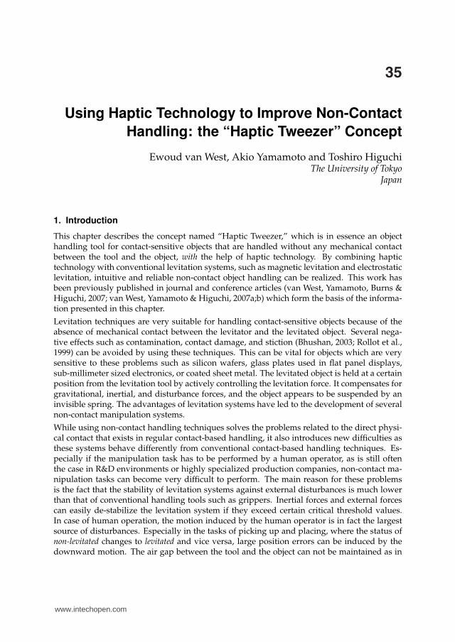
Fig. 1. A visual representation of the “Haptic Tweezer” concept. The human operator han-dles the non-contact levitator through the haptic device in order to augment in real-time thehandling performance.
these tasks, the object is supported on one side by for example a table, while the levitator ismoving down. If the motion is not stopped on time, contact between the levitator and objectwill occur, something which should be avoided at all cost in non-contact handling systems. Inregular contact-based handling, the direct physical contact with the object directly transmitsthe reaction forces from the support which will stop the downward motion. The contact forcealso gives a tactile feedback signal on the grasping status and on whether or not the object isin mid-air or at a support. In levitation systems however, this direct contact force is missingand instead, the operator feels the reaction force of the levitation system which is far weakerand thus more difficult to sense. This means that the operator can easily continue his down-ward motion even though the object has already reached the correct position. This problem iseven more eminent if the nominal levitation air gap between levitator and object is very smallwhich is often the case in levitation systems. However, for the development of a practicalnon-contact handling tool, these challenges have to be overcome.
The main objective of this research is to develop a mechatronic non-contact handling tool thatallows a human operator to perform simple manipulation tasks such as pick and place, in aneasy and intuitive way. In order to realize that objective and overcome the challenges in termsof stability and robustness of such a human operated tool, a solution is sought in employinghaptic technology to augment the human performance in real-time by active haptic feedback.This concept is named “Haptic Tweezer” and Fig. 1 shows some illustrations of the concept.The global idea is that haptic feedback compensates the disturbances coming from the humanoperator during manipulation tasks such as pick and place. By counteracting disturbancesthat would otherwise lead to instability (failure) of the levitation system, the haptic feedbackwill improve the performance of non-contact object manipulation. As the haptic feedback alsorestores in a sense the “feeling” of the levitated object, which was lost by the absence of phys-ical contact, the task can be performed in an intuitive way.
The approach that is used for research on the “Haptic Tweezer” concept, has a strong exper-imental character. Several prototypes have been developed to investigate different aspects ofthe “Haptic Tweezer” concept. Two different levitation techniques have been used, magneticlevitation and electrostatic levitation, and control strategies based on both impedance controland admittance control were used in order to realize satisfactory results. The results have
downwardmotion
downwardmotion
reaction forcesstop motion
weak reactionforce does notstop motion
contact betweenlevitator & object
release theobject
(a)
(b)
www.intechopen.com
Using Haptic Technology to Improve Non-Contact Handling: the “Haptic Tweezer” Concept 651
Pick Up Place
electrostaticlevitator
siliconwafer
hapticdevice
magneticlevitator just painted
car part
“haptic”roboticdevice downward
motion
downwardmotion
reaction forcesstop motion
weak reactionforce does notstop motion
contact betweenlevitator & object
release theobject
(a)
(b)
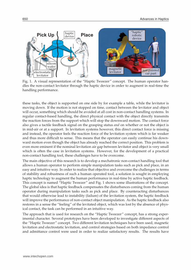
Fig. 2. Performing a placing task with (a) using direct physical contact, (b) using a non-contactlevitation tool
shown that the haptic feedback has a significant beneficial contribution for handling objectswithout contact.
The general concept of the “Haptic Tweezer” concept will be further explained in the follow-ing section. A brief discussion on related research that uses haptic technology for real-timeassisting applications is given in Section 3 and Section 4 will provide some basic backgroundinformation on magnetic and electrostatic levitation systems. A first prototype that uses mag-netic levitation and the impedance controlled haptic device PHANTOM Omni, is describedin Section 5. Another prototype is described in Section 6, which uses electrostatic levitationand an in-house developed haptic device based on the admittance control strategy. The con-clusions, describing the significance of the “Haptic Tweezer” concept, are given in the finalsection.
2. The “Haptic Tweezer” Concept
2.1 Basic concept
The concept of “Haptic Tweezer” uses the haptic device in a different configuration frommost haptic applications. Typically, haptic devices are used in virtual reality applications ortele-operation systems to transmit tactile information, such that the operator can interact ina natural manner with the designated system. However, the output capabilities of the hapticdevice can also be used to modify, in real-time, the operators motion or force for other pur-poses. The human operator and the haptic device can perform a task collaboratively in whichthe haptic device can exert corrective actions to improve the performance of the task. This isprecisely the objective of the “Haptic Tweezer” concept as the haptic device improves the taskof non-contact handling by using haptic feedback to reduce the human disturbances to thelevitated object.
The levitation systems used for non-contact handling have an independent stabilizing con-troller based on a position feedback loop. This same position information can be used as ameasure of stability of the levitation system, i.e. large disturbances will induce large positionerrors in the levitation system. The largest levitation errors that are induced by the human op-erator will occur during the tasks of picking up and placing. This problem is graphically shownby Fig. 2, where a placing task is performed by using direct physical contact (a), as well asby using a non-contact levitation tool (b). In regular contact-based handling, the motion is
www.intechopen.com
Advances in Haptics652
object
levitatoroperator
levitationcontroller
hapticcontroller
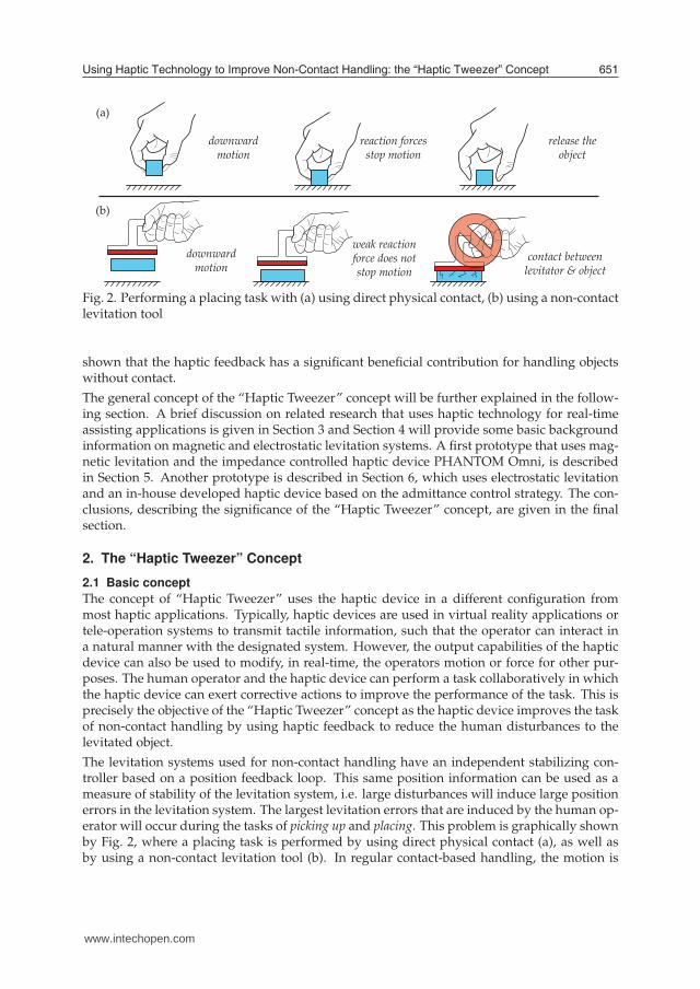
Fig. 3. Realization of an additional haptic force feedback loop
stopped by the reaction forces coming from the table, supporting the object. It also signals theoperator that the correct location has been reached. In case of non-contact handling however,the downward motion is not stopped by the reaction forces from the levitation system as theyare very weak. Furthermore, the human operator does not stop his motion as he can hardly“feel” the exact moment the object reaches the correct location. The induced position distur-bance is too large for the levitation system and the air gap between levitator and object cannot be maintained. The main focus of the “Haptic Tweezer” concept will lie in performanceimprovements for these pick and place tasks.
To compensate for the human disturbances, the haptic device will use the levitation positionerror to generate the haptic feedback to the operator. For example, if the human operator’sdownward motion reduces the air gap between the object and the levitation tool, the hapticdevice will generate a force to prevent this motion and thus avoid instability and damage.This is also shown in Fig. 3, where the haptic controller generates a feedback force Fhap,ε basedon the levitation position error ε. It is important to note that the haptic loop is an addition tothe levitation controller that controls the force Flev that stabilizes the leviation system. Withthe combination of the haptic controller and the levitation controller, a large induced positionerror will result in a reaction force from the levitation system (weak and hardly noticeable)and a force from the haptic device (strong) that counteract the position error. Furthermore,the haptic force sensation will naturally make the operator stop his downward motion as hecan “feel” the status of the task he is performing. The haptic device allows the human opera-tor to perform these pick and place tasks in a natural way and with improved performance asinstabilities can be prevented.
2.2 Other contributing haptic effects
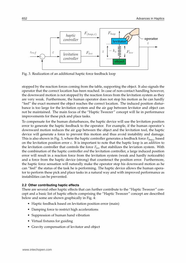
There are several other haptic effects that can further contribute to the “Haptic Tweezer” con-cept and a basic list of haptic effects comprising the “Haptic Tweezer” concept are describedbelow and some are shown graphically in Fig. 4:
• Haptic feedback based on levitation position error (main)
• Damping force to restrict high accelerations
• Suppression of human hand vibration
• Virtual fixtures for guiding
• Gravity compensation of levitator and object
guide to correctlocation
no misalignement
at place or pick upair gap can
become too small motion is restricted
by haptic device
Fhap
high accelerations
damping prevents losing the object
Fdamp
handvibration
not transmitted to levitator & object
(a) pick up or place
(c) filter hand vibration (d) virtual fixtures (guiding)
(b) motion too fast
hapticdevice
levitator
object
www.intechopen.com
Using Haptic Technology to Improve Non-Contact Handling: the “Haptic Tweezer” Concept 653
object
levitatoroperator
levitationcontroller
hapticcontroller
guide to correctlocation
no misalignement
at place or pick upair gap can
become too small motion is restricted
by haptic device
Fhap
high accelerations
damping prevents losing the object
Fdamp
handvibration
not transmitted to levitator & object
(a) pick up or place
(c) filter hand vibration (d) virtual fixtures (guiding)
(b) motion too fast
hapticdevice
levitator
object
Fig. 4. Several haptic effects that can contribute to the “Haptic Tweezer” concept
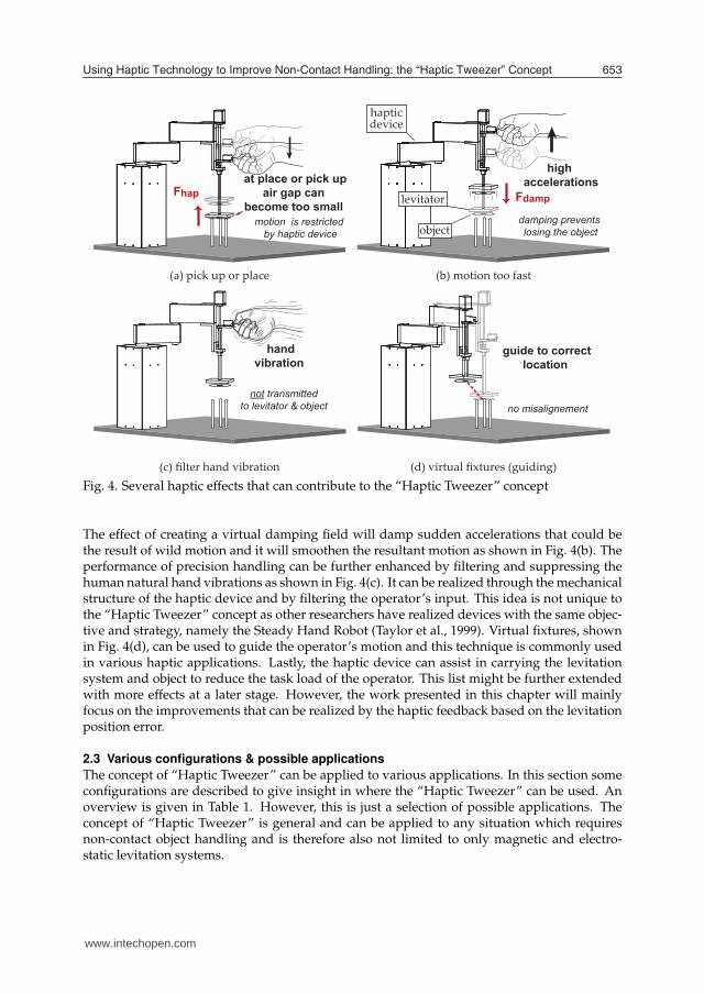
The effect of creating a virtual damping field will damp sudden accelerations that could bethe result of wild motion and it will smoothen the resultant motion as shown in Fig. 4(b). Theperformance of precision handling can be further enhanced by filtering and suppressing thehuman natural hand vibrations as shown in Fig. 4(c). It can be realized through the mechanicalstructure of the haptic device and by filtering the operator’s input. This idea is not unique tothe “Haptic Tweezer” concept as other researchers have realized devices with the same objec-tive and strategy, namely the Steady Hand Robot (Taylor et al., 1999). Virtual fixtures, shownin Fig. 4(d), can be used to guide the operator’s motion and this technique is commonly usedin various haptic applications. Lastly, the haptic device can assist in carrying the levitationsystem and object to reduce the task load of the operator. This list might be further extendedwith more effects at a later stage. However, the work presented in this chapter will mainlyfocus on the improvements that can be realized by the haptic feedback based on the levitationposition error.
2.3 Various configurations & possible applications
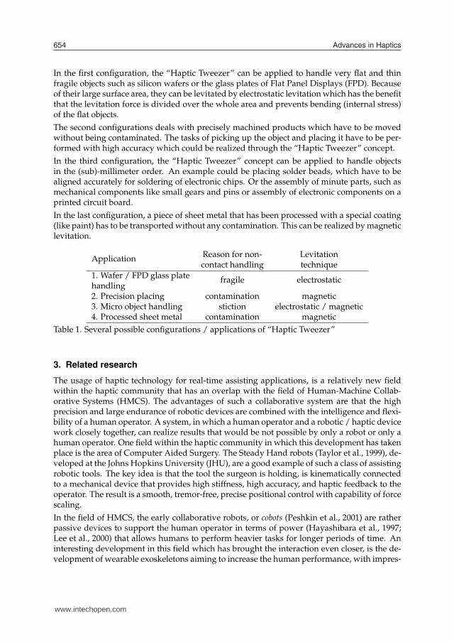
The concept of “Haptic Tweezer” can be applied to various applications. In this section someconfigurations are described to give insight in where the “Haptic Tweezer” can be used. Anoverview is given in Table 1. However, this is just a selection of possible applications. Theconcept of “Haptic Tweezer” is general and can be applied to any situation which requiresnon-contact object handling and is therefore also not limited to only magnetic and electro-static levitation systems.
www.intechopen.com
Advances in Haptics654
In the first configuration, the “Haptic Tweezer” can be applied to handle very flat and thinfragile objects such as silicon wafers or the glass plates of Flat Panel Displays (FPD). Becauseof their large surface area, they can be levitated by electrostatic levitation which has the benefitthat the levitation force is divided over the whole area and prevents bending (internal stress)of the flat objects.
The second configurations deals with precisely machined products which have to be movedwithout being contaminated. The tasks of picking up the object and placing it have to be per-formed with high accuracy which could be realized through the “Haptic Tweezer” concept.
In the third configuration, the “Haptic Tweezer” concept can be applied to handle objectsin the (sub)-millimeter order. An example could be placing solder beads, which have to bealigned accurately for soldering of electronic chips. Or the assembly of minute parts, such asmechanical components like small gears and pins or assembly of electronic components on aprinted circuit board.
In the last configuration, a piece of sheet metal that has been processed with a special coating(like paint) has to be transported without any contamination. This can be realized by magneticlevitation.
Reason for non- LevitationApplication
contact handling technique
1. Wafer / FPD glass platehandling
fragile electrostatic
2. Precision placing contamination magnetic3. Micro object handling stiction electrostatic / magnetic4. Processed sheet metal contamination magnetic
Table 1. Several possible configurations / applications of “Haptic Tweezer”
3. Related research
The usage of haptic technology for real-time assisting applications, is a relatively new fieldwithin the haptic community that has an overlap with the field of Human-Machine Collab-orative Systems (HMCS). The advantages of such a collaborative system are that the highprecision and large endurance of robotic devices are combined with the intelligence and flexi-bility of a human operator. A system, in which a human operator and a robotic / haptic devicework closely together, can realize results that would be not possible by only a robot or only ahuman operator. One field within the haptic community in which this development has takenplace is the area of Computer Aided Surgery. The Steady Hand robots (Taylor et al., 1999), de-veloped at the Johns Hopkins University (JHU), are a good example of such a class of assistingrobotic tools. The key idea is that the tool the surgeon is holding, is kinematically connectedto a mechanical device that provides high stiffness, high accuracy, and haptic feedback to theoperator. The result is a smooth, tremor-free, precise positional control with capability of forcescaling.
In the field of HMCS, the early collaborative robots, or cobots (Peshkin et al., 2001) are ratherpassive devices to support the human operator in terms of power (Hayashibara et al., 1997;Lee et al., 2000) that allows humans to perform heavier tasks for longer periods of time. Aninteresting development in this field which has brought the interaction even closer, is the de-velopment of wearable exoskeletons aiming to increase the human performance, with impres-
www.intechopen.com
Using Haptic Technology to Improve Non-Contact Handling: the “Haptic Tweezer” Concept 655
sive results (Kazerooni, 1996; Kazerooni & Steger, 2006). In these systems, a close interactionbetween human and device is required and using haptic signals can facilitate this interactionas it allows more natural and comfortable operation. The fast processing of haptic signals byhumans makes that haptic technology plays a key role for realizing systems that are intuitiveto operate. Haptic signals can be used to present key information to an operator in for exam-ple augmented reality systems (Azuma et al., 2001; Azuma, 1997) to make the operator acceptall the presented information more easily.
The possibilities are even larger as haptic devices can even transform sensory information,such as optical information, by presenting it haptically through the sense of touch. The Smart-Tool (Nojima et al., 2002) is a good example of such a system as it converts or “haptizes”information in real-time from an additional sensor into a haptic feedback. One example fromtheir work shows the potential of such a system. The end-effector of the haptic device consistsof the tool with an additional sensor, in this case, a surgical scalpel fitted with a reflectivitysensor. The objective will be to remove some unwanted tissue, for example a cancer growth,from a healthy organ, without damaging the healthy organ. For the experiment, the humantissue is replaced by a hard-boiled egg. A threshold in reflectivity is defined as a boundarybetween tissue that is safe to cut (egg white) and vital tissue (the egg yolk) that should beunharmed during a surgical cutting procedure. When the reflectivity sensor senses the eggyolk, a repulsive force is generated to compensate the operators cutting force. In such a way,the egg can be dissected without any effort from the operator. The strength lies in the easewith which such an operation can be performed and it shows the great potential of employinghaptic technology. In addition, the usage of virtual fixtures (Rosenberg, 1993) can further en-hance performance of some tasks as the operator’s motion can be confined or guided, whichincreases performance of manipulation in for example medical tasks (Bettini et al., 2004; Linet al., 2006).
4. Magnetic and Electrostatic Levitation
This section provides a brief introduction to the magnetic and electrostatic levitation systemsused in this research. Both techniques have been researched by other researchers, so manyliterature is available on these subjects and this section is largely based on some of these works(Jin et al., 1994; 1995; Schweitzer et al., 1994).
4.1 Theoretical equations of motion
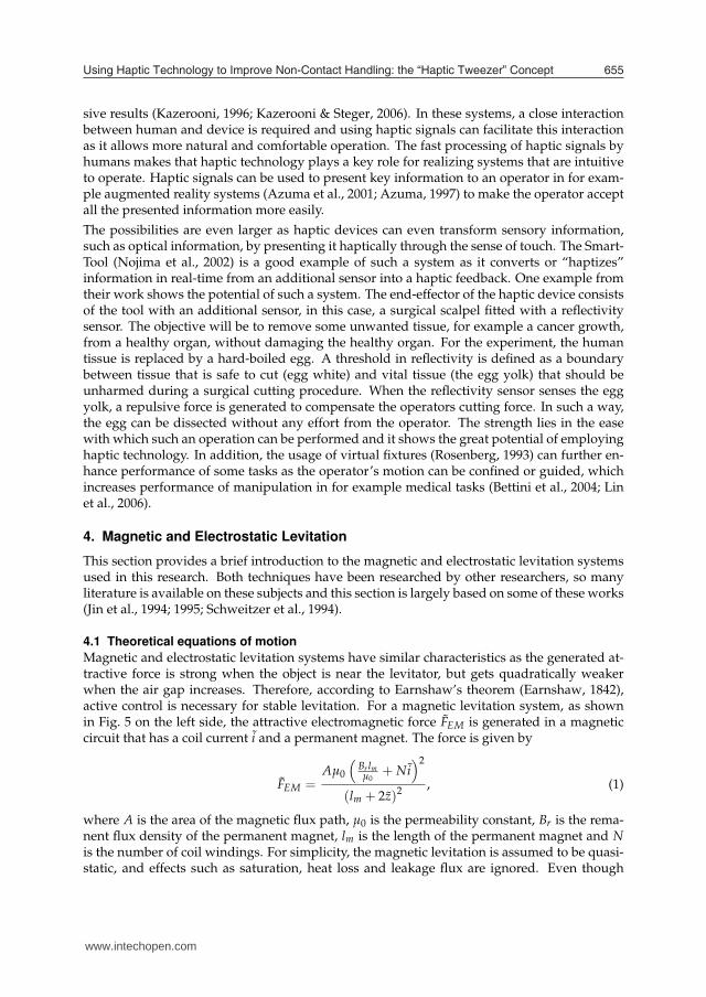
Magnetic and electrostatic levitation systems have similar characteristics as the generated at-tractive force is strong when the object is near the levitator, but gets quadratically weakerwhen the air gap increases. Therefore, according to Earnshaw’s theorem (Earnshaw, 1842),active control is necessary for stable levitation. For a magnetic levitation system, as shownin Fig. 5 on the left side, the attractive electromagnetic force FEM is generated in a magneticcircuit that has a coil current i and a permanent magnet. The force is given by
FEM =Aµ0
(
Br lmµ0
+ Ni)2
(lm + 2z)2, (1)
where A is the area of the magnetic flux path, µ0 is the permeability constant, Br is the rema-nent flux density of the permanent magnet, lm is the length of the permanent magnet and Nis the number of coil windings. For simplicity, the magnetic levitation is assumed to be quasi-static, and effects such as saturation, heat loss and leakage flux are ignored. Even though
www.intechopen.com
Advances in Haptics656
+ + + + + + + +
+ + + + + + + +- - - - - - - -
- - - - - - - -
suspended object
-1
electrode
permanent magnet
coilelectrode
(virtual ground)
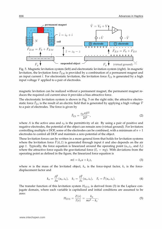
Fig. 5. Magnetic levitation system (left) and electrostatic levitation system (right). In magneticlevitation, the levitation force FEM is provided by a combination of a permanent magnet andan input current i. For electrostatic levitation, the levitation force FES is generated by a highinput voltage V applied to a pair of electrodes.
magnetic levitation can be realized without a permanent magnet, the permanent magnet re-duces the required coil current since it provides a bias attractive force.
The electrostatic levitation system is shown in Fig. 5 on the right side; the attractive electro-static force FES is the result of an electric field that is generated by applying a high voltage V
to a pair of electrodes. The force is given by
FES =ε0 AV2
2z2, (2)
where A is the active area and ε0 is the permittivity of air. By using a pair of positive andnegative electrodes, the potential of the object can remain zero (virtual ground). For levitatorscontrolling multiple n DOF, some of the electrodes can be combined, with a minimum of n+ 1electrodes to control all DOF and maintain a zero potential of the object.
These levitation forces can be written in a more general form that holds for levitation systemswhere the levitation force F(u, z) is generated through input u and also depends on the airgap z. Typically, the force equation is linearized around the operating point (ue,ze, and Fe)where the attractive force equals the gravitational force (Fe = mg). With deviations from theoperating point as defined in the figure, the linearized force equation is
mz = kuu + kzz, (3)
where m is the mass of the levitated object, ku is the force-input factor, kz is the force-displacement factor and
ku =δF
δu(ue, ze), kz =
δF
δz(ue, ze), Fe = F(ue, ze). (4)
The transfer function of this levitation system HSYS, is derived from (3) in the Laplace con-jugate domain, where each variable is capitalized and initial conditions are assumed to bezero:
HSYS =Z(s)
I(s)=
ku
ms2− kz
. (5)
roll
pitch
yawgap
PID
PD
PD
+
+
++
+
+
+
-
-
-
three DOFelectrostatic
levitator
one DOFmagneticlevitator
-
PD++
+ -
(c)
(b)(a) zero-powerfeedback loop
www.intechopen.com
Using Haptic Technology to Improve Non-Contact Handling: the “Haptic Tweezer” Concept 657
+ + + + + + + +
+ + + + + + + +- - - - - - - -
- - - - - - - -
suspended object
-1
electrode
permanent magnet
coilelectrode
(virtual ground)
roll
pitch
yawgap
PID
PD
PD
+
+
++
+
+
+
-
-
-
three DOFelectrostatic
levitator
one DOFmagneticlevitator
-
PD++
+ -
(c)
(b)(a) zero-powerfeedback loop
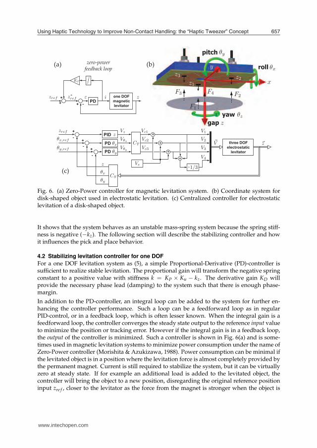
Fig. 6. (a) Zero-Power controller for magnetic levitation system. (b) Coordinate system fordisk-shaped object used in electrostatic levitation. (c) Centralized controller for electrostaticlevitation of a disk-shaped object.
It shows that the system behaves as an unstable mass-spring system because the spring stiff-ness is negative (−kz). The following section will describe the stabilizing controller and howit influences the pick and place behavior.
4.2 Stabilizing levitation controller for one DOF
For a one DOF levitation system as (5), a simple Proportional-Derivative (PD)-controller issufficient to realize stable levitation. The proportional gain will transform the negative springconstant to a positive value with stiffness k = KP × Ku − kz. The derivative gain KD willprovide the necessary phase lead (damping) to the system such that there is enough phase-margin.
In addition to the PD-controller, an integral loop can be added to the system for further en-hancing the controller performance. Such a loop can be a feedforward loop as in regularPID-control, or in a feedback loop, which is often lesser known. When the integral gain is afeedforward loop, the controller converges the steady state output to the reference input valueto minimize the position or tracking error. However if the integral gain is in a feedback loop,the output of the controller is minimized. Such a controller is shown in Fig. 6(a) and is some-times used in magnetic levitation systems to minimize power consumption under the name ofZero-Power controller (Morishita & Azukizawa, 1988). Power consumption can be minimal ifthe levitated object is in a position where the levitation force is almost completely provided bythe permanent magnet. Current is still required to stabilize the system, but it can be virtuallyzero at steady state. If for example an additional load is added to the levitated object, thecontroller will bring the object to a new position, disregarding the original reference positioninput zre f , closer to the levitator as the force from the magnet is stronger when the object is
www.intechopen.com
Advances in Haptics658
closer. It can be perceived as that the integral loop modifies the reference input to z∗re f , which
resembles a position in which the gravitational load is always balanced by the bias force ofthe levitation system (e.g. permanent magnet in magnetic levitation). The main benefit ofZero-Power controlled levitation systems and the reason why it is so suitable for non-contacttransportation systems, is that the weight of the object can vary while still maintaining lowpower consumption for the manipulation task.
The integral gain loop in the levitation controller has another effect that is used in the placingtask. The presence of such an integral loop allows to release the levitated objects automaticallywithout any manual switching. This phenomena, which is described extensively in (van Westet al., 2008), uses the integral controller wind up to reduce the holding force when a positionerror is temporarily forced to the levitated object. When, for example, the levitated object isbrought to the desired location in the placing task, making contact at that location will reducethe air gap between levitator and object (the position error). For both Zero-Power and PIDcontrol, the result of this position error is that the controller will aim to increase the air gapby reducing the attractive force. The key point is that the integral gain will keep reducingthe attractive force even if the position error is constant, due to the integral action. After sometime, the attractive force has been reduced so much, that when the levitator moves away againand the position error changes sign, the object can not re-levitate the object and the placinghas been realized automatically. Manually disabling the levitation force, on the other hand,would require precise timing as a release too early can drop the object, and a release too latecan force the object to “stick” to the levitator. Automatic release will relief the operator in thisregard and it contributes to perform the manipulation task intuitively. In the experimentalresults of the placing task, a more detailed description will be given using the experimentaldata.
For the picking up task however, having an integral gain in the levitation controller can be un-desired for the same reason: integral controller wind up. If for example the picking up motionis too slow, the controller will increase the attractive force so much, that when the position isreached from which levitation is possible, the attractive force can be so large that instead ofgoing to a stable position, it will “jump” and stick to the levitator. So in order to use the bene-ficial effects of the integral gain loop only when it is needed, it can be automatically switchedon just after initial levitation (picking up) by a relay switch.
4.3 Multiple DOF levitation systems
While some objects can be levitated by actively controlling only one DOF, as will be shown inthe first prototype of magnetic levitation of an iron ball, for most objects, multiple DOF haveto be controlled for realizing stable levitation. For this purpose, multiple actuators and gapsensors have to be placed strategically around the object. However, it is not always necessaryto control all six DOF with active control, as often a passive restoring force is present thatnaturally stabilizes some of the DOF. For levitating thin circular objects like an aluminiumdisk for example, it is natural to control only three DOF, namely the gap z, the roll θx, and thepitch θy, shown in Fig. 6(b). The lateral x- and y-direction are stabilized by a passive force thataligns the object with the levitator because in this position, the levitation field potential is thehighest (Woo et al., 1995). As the side area is too small to place additional actuators, this forcecannot be enhanced by means of control. Lastly, control of the yaw rotation θz is unnecessarydue to the rotation symmetry of the object. As the actuators are all acting on the top surfaceof the object, the levitator can have the same form factor as the levitated object, which is veryuseful in the manipulation tasks of picking up and placing, where actuators on the side or
www.intechopen.com
Using Haptic Technology to Improve Non-Contact Handling: the “Haptic Tweezer” Concept 659
bottom could be obstructive.
The controller structure for levitating an aluminium disk by electrostatic levitation is shownin Fig. 6(c) and it has a centralized control structure as each DOF is controlled by its owncontroller (Jin et al., 1995). The relative position of the disk is measured by three gap sensors,which are radially distributed around the z-axis at a radius Rs. Since these gap sensors willmeasure the distance zi, (i = 1, 2, 3) in local coordinates, they have to be transformed by atransformation matrix CS to the correct DOF:
zθx
θy
=
1/3 1/3 1/3−23Rs
13Rs
13Rs
0 −1√3Rs
1√3Rs
︸ ︷︷ ︸
CS
×
z1
z2
z3
, (6)
which assumes that tilting angles are small (sin(θ) ≈ θ). As the actuators have the same radialdistribution as the gap sensors, the output from the controllers have to be transformed onceagain to generate the input signal for each actuator:
CT =
−1/3 23Ra
0
−1/3 −13Ra
1√3Ra
−1/3 −13Ra
−1√3Ra
, (7)
where Ra is the radius at which the actuating force occurs. By using CT as the output transfor-mation matrix, the proportional controller values of KP will have the correct physical value ofstiffness realized by control once they are multiplied with the force-input value of Ku.
In this case of electrostatic levitation, the positive electrodes are the controlling electrodes asthey receive the output voltages of the controller Vi, i = 1, 2, 3. The negative electrodes re-ceive a voltage that will simply maintain the total potential of the object at zero volt by settingV4 = −1/3 ∑ Vi, i = 1, 2, 3.
5. Prototype using magnetic levitation, PHANTOM Omni, and impedance control
The first prototype is realized to show how a combination of levitation system and hapticinterface will perform. This prototype combines a magnetic levitation system with a com-mercially available haptic interface, the PHANTOM Omni (Sensable Technologies). This sec-tion describes the control strategy, the realized prototype, and the experiments that were per-formed to evaluate the overall performance.
5.1 Strategy for impedance controlled haptic devices
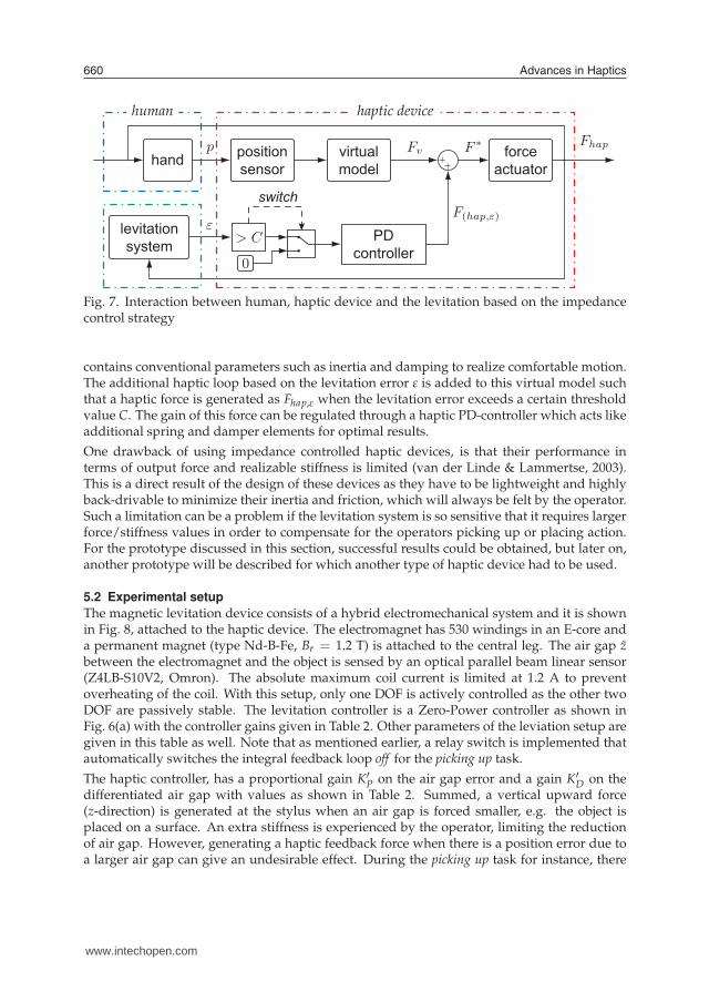
For the first prototype, the haptic device PHANTOM Omni has been used as it is commer-cially available at relatively low cost, and it can be easily equipped with a simple one DOFmagnetic levitation system. The PHANTOM Omni is a haptic device based on the impedancecontrol strategy, measuring the operator’s position input and feeding back the haptic force(position in / force out). The implementation of the “Haptic Tweezer” concept for such adevice is graphically shown in Fig. 7. The upper part shows the impedance structure of thehaptic device with the position sensor measuring the human motion p, and the force actuatorexerts the haptic feedback force Fhap based on a reference force F∗. One component of this ref-erence force signal, Fv, comes from a virtual model that defines the haptic environment, and it
www.intechopen.com
Advances in Haptics660
levitationsystem
positionsensorhand
PDcontroller
virtualmodel
forceactuator
switch
human haptic device
Fig. 7. Interaction between human, haptic device and the levitation based on the impedancecontrol strategy
contains conventional parameters such as inertia and damping to realize comfortable motion.The additional haptic loop based on the levitation error ε is added to this virtual model suchthat a haptic force is generated as Fhap,ε when the levitation error exceeds a certain thresholdvalue C. The gain of this force can be regulated through a haptic PD-controller which acts likeadditional spring and damper elements for optimal results.
One drawback of using impedance controlled haptic devices, is that their performance interms of output force and realizable stiffness is limited (van der Linde & Lammertse, 2003).This is a direct result of the design of these devices as they have to be lightweight and highlyback-drivable to minimize their inertia and friction, which will always be felt by the operator.Such a limitation can be a problem if the levitation system is so sensitive that it requires largerforce/stiffness values in order to compensate for the operators picking up or placing action.For the prototype discussed in this section, successful results could be obtained, but later on,another prototype will be described for which another type of haptic device had to be used.
5.2 Experimental setup
The magnetic levitation device consists of a hybrid electromechanical system and it is shownin Fig. 8, attached to the haptic device. The electromagnet has 530 windings in an E-core anda permanent magnet (type Nd-B-Fe, Br = 1.2 T) is attached to the central leg. The air gap z
between the electromagnet and the object is sensed by an optical parallel beam linear sensor(Z4LB-S10V2, Omron). The absolute maximum coil current is limited at 1.2 A to preventoverheating of the coil. With this setup, only one DOF is actively controlled as the other twoDOF are passively stable. The levitation controller is a Zero-Power controller as shown inFig. 6(a) with the controller gains given in Table 2. Other parameters of the leviation setup aregiven in this table as well. Note that as mentioned earlier, a relay switch is implemented thatautomatically switches the integral feedback loop off for the picking up task.
The haptic controller, has a proportional gain K′
P on the air gap error and a gain K′
D on thedifferentiated air gap with values as shown in Table 2. Summed, a vertical upward force(z-direction) is generated at the stylus when an air gap is forced smaller, e.g. the object isplaced on a surface. An extra stiffness is experienced by the operator, limiting the reductionof air gap. However, generating a haptic feedback force when there is a position error due toa larger air gap can give an undesirable effect. During the picking up task for instance, there
xz
y
threshold
central placing point
levitationcontroller
centering effectgravity compensation
inertia effect
www.intechopen.com
Using Haptic Technology to Improve Non-Contact Handling: the “Haptic Tweezer” Concept 661
levitationsystem
positionsensorhand
PDcontroller
virtualmodel
forceactuator
switch
human haptic device
xz
y
threshold
central placing point
levitationcontroller
centering effectgravity compensation
inertia effect
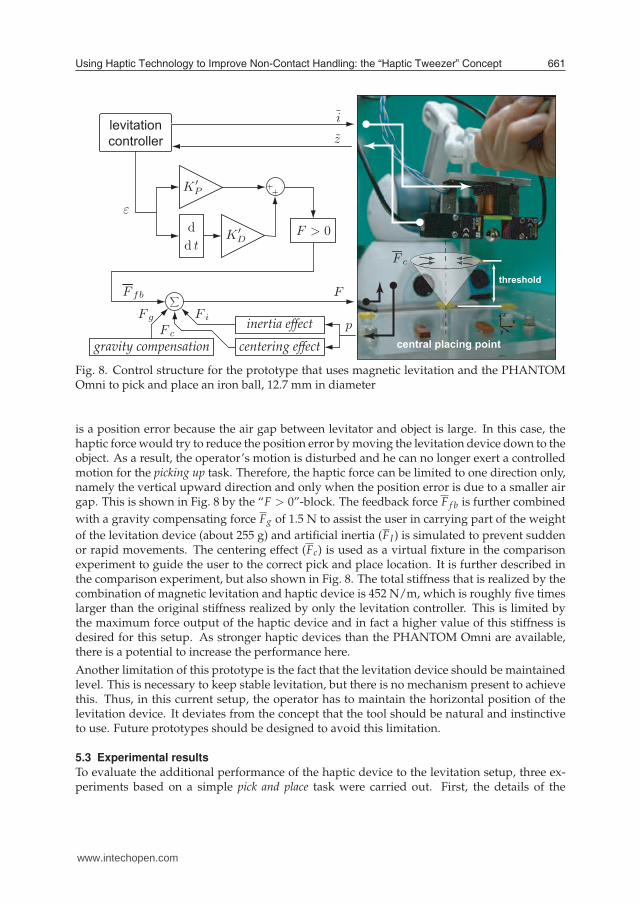
Fig. 8. Control structure for the prototype that uses magnetic levitation and the PHANTOMOmni to pick and place an iron ball, 12.7 mm in diameter
is a position error because the air gap between levitator and object is large. In this case, thehaptic force would try to reduce the position error by moving the levitation device down to theobject. As a result, the operator’s motion is disturbed and he can no longer exert a controlledmotion for the picking up task. Therefore, the haptic force can be limited to one direction only,namely the vertical upward direction and only when the position error is due to a smaller airgap. This is shown in Fig. 8 by the “F > 0”-block. The feedback force F f b is further combined
with a gravity compensating force Fg of 1.5 N to assist the user in carrying part of the weight
of the levitation device (about 255 g) and artificial inertia (FI) is simulated to prevent suddenor rapid movements. The centering effect (Fc) is used as a virtual fixture in the comparisonexperiment to guide the user to the correct pick and place location. It is further described inthe comparison experiment, but also shown in Fig. 8. The total stiffness that is realized by thecombination of magnetic levitation and haptic device is 452 N/m, which is roughly five timeslarger than the original stiffness realized by only the levitation controller. This is limited bythe maximum force output of the haptic device and in fact a higher value of this stiffness isdesired for this setup. As stronger haptic devices than the PHANTOM Omni are available,there is a potential to increase the performance here.
Another limitation of this prototype is the fact that the levitation device should be maintainedlevel. This is necessary to keep stable levitation, but there is no mechanism present to achievethis. Thus, in this current setup, the operator has to maintain the horizontal position of thelevitation device. It deviates from the concept that the tool should be natural and instinctiveto use. Future prototypes should be designed to avoid this limitation.
5.3 Experimental results
To evaluate the additional performance of the haptic device to the levitation setup, three ex-periments based on a simple pick and place task were carried out. First, the details of the
www.intechopen.com
Advances in Haptics662
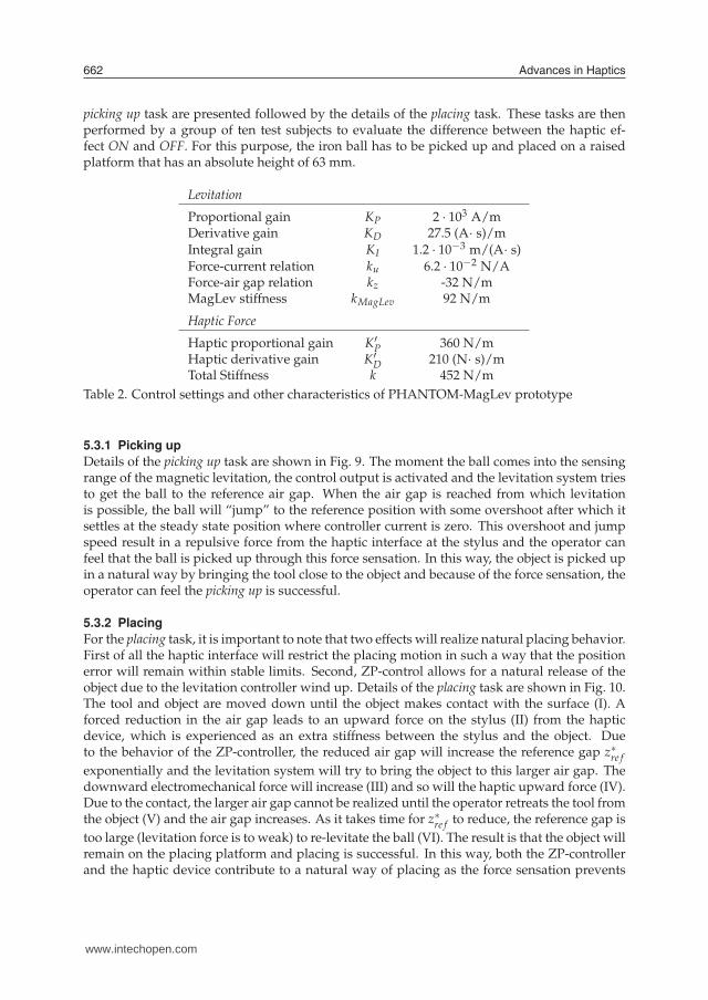
picking up task are presented followed by the details of the placing task. These tasks are thenperformed by a group of ten test subjects to evaluate the difference between the haptic ef-fect ON and OFF. For this purpose, the iron ball has to be picked up and placed on a raisedplatform that has an absolute height of 63 mm.
Levitation
Proportional gain KP 2 · 103 A/mDerivative gain KD 27.5 (A· s)/mIntegral gain KI 1.2 · 10−3 m/(A· s)Force-current relation ku 6.2 · 10−2 N/AForce-air gap relation kz -32 N/mMagLev stiffness kMagLev 92 N/m
Haptic Force
Haptic proportional gain K′
P 360 N/mHaptic derivative gain K′
D 210 (N· s)/mTotal Stiffness k 452 N/m
Table 2. Control settings and other characteristics of PHANTOM-MagLev prototype
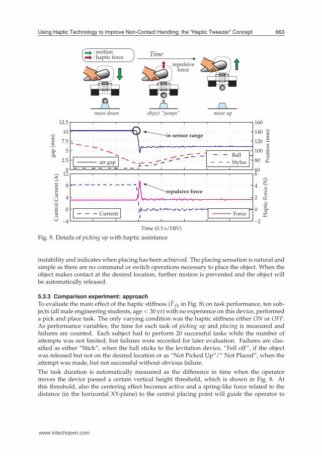
5.3.1 Picking up
Details of the picking up task are shown in Fig. 9. The moment the ball comes into the sensingrange of the magnetic levitation, the control output is activated and the levitation system triesto get the ball to the reference air gap. When the air gap is reached from which levitationis possible, the ball will “jump” to the reference position with some overshoot after which itsettles at the steady state position where controller current is zero. This overshoot and jumpspeed result in a repulsive force from the haptic interface at the stylus and the operator canfeel that the ball is picked up through this force sensation. In this way, the object is picked upin a natural way by bringing the tool close to the object and because of the force sensation, theoperator can feel the picking up is successful.
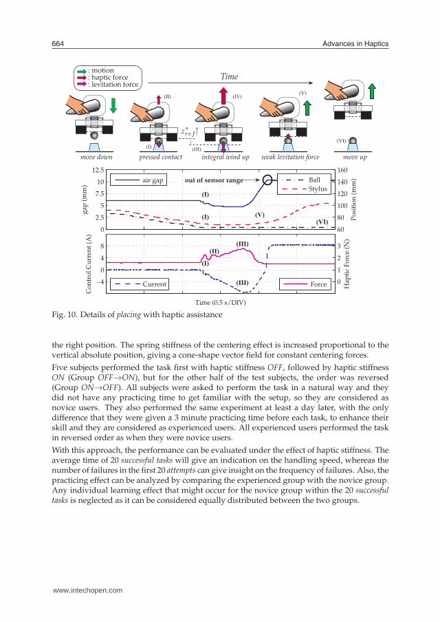
5.3.2 Placing
For the placing task, it is important to note that two effects will realize natural placing behavior.First of all the haptic interface will restrict the placing motion in such a way that the positionerror will remain within stable limits. Second, ZP-control allows for a natural release of theobject due to the levitation controller wind up. Details of the placing task are shown in Fig. 10.The tool and object are moved down until the object makes contact with the surface (I). Aforced reduction in the air gap leads to an upward force on the stylus (II) from the hapticdevice, which is experienced as an extra stiffness between the stylus and the object. Dueto the behavior of the ZP-controller, the reduced air gap will increase the reference gap z∗re f
exponentially and the levitation system will try to bring the object to this larger air gap. Thedownward electromechanical force will increase (III) and so will the haptic upward force (IV).Due to the contact, the larger air gap cannot be realized until the operator retreats the tool fromthe object (V) and the air gap increases. As it takes time for z∗re f to reduce, the reference gap is
too large (levitation force is to weak) to re-levitate the ball (VI). The result is that the object willremain on the placing platform and placing is successful. In this way, both the ZP-controllerand the haptic device contribute to a natural way of placing as the force sensation prevents
Timerepulsive
force
move down object “jumps” move up
: motion: haptic force
www.intechopen.com
Using Haptic Technology to Improve Non-Contact Handling: the “Haptic Tweezer” Concept 663
Timerepulsive
force
move down object “jumps” move up
: motion: haptic force
0
2.5
5
7.5
10
12.5
gap
(m
m)
60
80
100
120
140
160
Po
siti
on
(m
m)
air gap
Ball
Stylus
−4
0
4
8
12
Co
ntr
ol
Cu
rren
t (A
)
Time (0.5 s/DIV)
−2
0
2
4
6
Hap
tic
Fo
rce
(N)
Current Force
in sensor range
repulsive force
Fig. 9. Details of picking up with haptic assistance
instability and indicates when placing has been achieved. The placing sensation is natural andsimple as there are no command or switch operations necessary to place the object. When theobject makes contact at the desired location, further motion is prevented and the object willbe automatically released.
5.3.3 Comparison experiment: approach
To evaluate the main effect of the haptic stiffness (F f b in Fig. 8) on task performance, ten sub-jects (all male engineering students, age < 30 yr) with no experience on this device, performeda pick and place task. The only varying condition was the haptic stiffness either ON or OFF.As performance variables, the time for each task of picking up and placing is measured andfailures are counted. Each subject had to perform 20 successful tasks while the number ofattempts was not limited, but failures were recorded for later evaluation. Failures are clas-sified as either “Stick”, when the ball sticks to the levitation device, “Fell off”, if the objectwas released but not on the desired location or as “Not Picked Up”/“ Not Placed”, when theattempt was made, but not successful without obvious failure.
The task duration is automatically measured as the difference in time when the operatormoves the device passed a certain vertical height threshold, which is shown in Fig. 8. Atthis threshold, also the centering effect becomes active and a spring-like force related to thedistance (in the horizontal XY-plane) to the central placing point will guide the operator to
www.intechopen.com
Advances in Haptics664
Time: motion: haptic force: levitation force
move down pressed contact integral wind up weak levitation force move up(I)
(II) (IV)(V)
(VI)(III)
0
2.5
5
7.5
10
12.5
gap
(m
m)
60
80
100
120
140
160
Po
siti
on
(m
m)air gap Ball
Stylus
−4
0
4
8
Co
ntr
ol
Cu
rren
t (A
)
Time (0.5 s/DIV)
0
1
2
3
Hap
tic
Fo
rce
(N)
Current Force
out of sensor range
(I)
(I) (V)(VI)
(I)
(II)(III)
(III)
Fig. 10. Details of placing with haptic assistance
the right position. The spring stiffness of the centering effect is increased proportional to thevertical absolute position, giving a cone-shape vector field for constant centering forces.
Five subjects performed the task first with haptic stiffness OFF, followed by haptic stiffnessON (Group OFF→ON), but for the other half of the test subjects, the order was reversed(Group ON→OFF). All subjects were asked to perform the task in a natural way and theydid not have any practicing time to get familiar with the setup, so they are considered asnovice users. They also performed the same experiment at least a day later, with the onlydifference that they were given a 3 minute practicing time before each task, to enhance theirskill and they are considered as experienced users. All experienced users performed the taskin reversed order as when they were novice users.
With this approach, the performance can be evaluated under the effect of haptic stiffness. Theaverage time of 20 successful tasks will give an indication on the handling speed, whereas thenumber of failures in the first 20 attempts can give insight on the frequency of failures. Also, thepracticing effect can be analyzed by comparing the experienced group with the novice group.Any individual learning effect that might occur for the novice group within the 20 successfultasks is neglected as it can be considered equally distributed between the two groups.
0.0
0.5
1.0
1.5
2.0
2.5
3.0
Subj. FSubj. G
Subj. HSubj. I
Subj. J
Mea
n +/
- 1 S
D T
ask
time
[s] Pick Up, group OFF ON
stiffness OFFstiffness ON
0.0
0.5
1.0
1.5
2.0
2.5
3.0
Subj. FSubj. G
Subj. HSubj. I
Subj. J
Mea
n +/
- 1 S
D T
ask
time
[s] Place, group OFF ON
0.0
0.5
1.0
1.5
2.0
2.5
3.0
Subj. ASubj. B
Subj. CSubj. D
Subj. EM
ean
+/- 1
SD
Tas
k tim
e [s
] Place, group ON OFF
Place, group OFF ONPlace, group ON OFF
0.0
0.5
1.0
1.5
2.0
2.5
3.0
Subj. ASubj. B
Subj. CSubj. D
Subj. E
Mea
n +/
- 1 S
D T
ask
time
[s] Pick Up, group ON OFF
Pick Up, group OFF ONPick Up, group ON OFF
stiffness OFFstiffness ON
t(38)=4.40p<.001 ***
t(38)=24.4p<.001 ***
t(38)=.60p=.553
t(38)=5.39p<.001 ***
t(38)=3.55p=.001 ***
t(38)=.82p=.415
t(38)=14.6p<.001 ***
t(38)=2.52p=.016 *
t(38)=7.20p<.001 ***
t(38)=.79p=.432
t(38)=30.0p<.001 ***
t(38)=5.17.p<.001 ***
t(38)=8.98p<.001 ***
t(38)=18.0p<.001 ***
t(38)=3.79p=.001 **
t(38)=33.1p<.001 ***
t(38)=8.22p<.001 ***
t(38)=8.10p<.001 ***
t(38)=9.52p<.001 ***
t(38)=4.55p<.001 ***
0.0
0.5
1.0
1.5
2.0
2.5
3.0
Subj. ASubj. B
Subj. CSubj. D
Subj. E
Mea
n +/
- 1 S
D T
ask
time
[s]
stiffness OFFstiffness ON
novice
0.0
0.5
1.0
1.5
2.0
2.5
3.0
Subj. FSubj. G
Subj. HSubj. I
Subj. J
Mea
n +/
- 1 S
D T
ask
time
[s]
stiffness OFFstiffness ON
0.0
0.5
1.0
1.5
2.0
2.53.0
Subj. FSubj. G
Subj. HSubj. I
Subj. J
Mea
n +/
- 1 S
D T
ask
time
[s]
0.0
0.5
1.0
1.5
2.0
2.53.0
Subj. ASubj. B
Subj. CSubj. D
Subj. E
Mea
n +/
- 1 S
D T
ask
time
[s]
t(38)=2.18p=.035 *
t(38)=2.74p=.009 **
t(38)=8.38p<.001 ***
t(38)=7.41p<.001 ***
t(38)=2.07p=.045 *
t(38)=4.41p<.001 ***
t(38)=3.26p=.002 **
t(38)=8.02p<.001 ***
t(38)=8.84p<.001 ***
t(38)=2.64p=.012 *
t(38)=3.71p=.001 **
t(38)=.87p=.389
t(38)=7.27p<.001 ***
t(38)=-1.54p=.133
t(38)=1.81p=.078
t(38)=3.57p=.001 **
t(38)=5.04p<.001 ***
t(38)=10.1p<.001 ***
t(38)=-.35p=.732
t(38)=-.47p=.640
novice
novicenovice
experienced experienced
experiencedexperienced
www.intechopen.com
Using Haptic Technology to Improve Non-Contact Handling: the “Haptic Tweezer” Concept 665
Time: motion: haptic force: levitation force
move down pressed contact integral wind up weak levitation force move up(I)
(II) (IV)(V)
(VI)(III)
(I)
(I) (V)(VI)
(I)
(II)(III)
(III)
0.0
0.5
1.0
1.5
2.0
2.5
3.0
Subj. FSubj. G
Subj. HSubj. I
Subj. J
Mea
n +/
- 1 S
D T
ask
time
[s] Pick Up, group OFF ON
stiffness OFFstiffness ON
0.0
0.5
1.0
1.5
2.0
2.5
3.0
Subj. FSubj. G
Subj. HSubj. I
Subj. J
Mea
n +/
- 1 S
D T
ask
time
[s] Place, group OFF ON
0.0
0.5
1.0
1.5
2.0
2.5
3.0
Subj. ASubj. B
Subj. CSubj. D
Subj. E
Mea
n +/
- 1 S
D T
ask
time
[s] Place, group ON OFF
Place, group OFF ONPlace, group ON OFF
0.0
0.5
1.0
1.5
2.0
2.5
3.0
Subj. ASubj. B
Subj. CSubj. D
Subj. E
Mea
n +/
- 1 S
D T
ask
time
[s] Pick Up, group ON OFF
Pick Up, group OFF ONPick Up, group ON OFF
stiffness OFFstiffness ON
t(38)=4.40p<.001 ***
t(38)=24.4p<.001 ***
t(38)=.60p=.553
t(38)=5.39p<.001 ***
t(38)=3.55p=.001 ***
t(38)=.82p=.415
t(38)=14.6p<.001 ***
t(38)=2.52p=.016 *
t(38)=7.20p<.001 ***
t(38)=.79p=.432
t(38)=30.0p<.001 ***
t(38)=5.17.p<.001 ***
t(38)=8.98p<.001 ***
t(38)=18.0p<.001 ***
t(38)=3.79p=.001 **
t(38)=33.1p<.001 ***
t(38)=8.22p<.001 ***
t(38)=8.10p<.001 ***
t(38)=9.52p<.001 ***
t(38)=4.55p<.001 ***
0.0
0.5
1.0
1.5
2.0
2.5
3.0
Subj. ASubj. B
Subj. CSubj. D
Subj. E
Mea
n +/
- 1 S
D T
ask
time
[s]
stiffness OFFstiffness ON
novice
0.0
0.5
1.0
1.5
2.0
2.5
3.0
Subj. FSubj. G
Subj. HSubj. I
Subj. J
Mea
n +/
- 1 S
D T
ask
time
[s]
stiffness OFFstiffness ON
0.0
0.5
1.0
1.5
2.0
2.53.0
Subj. FSubj. G
Subj. HSubj. I
Subj. J
Mea
n +/
- 1 S
D T
ask
time
[s]
0.0
0.5
1.0
1.5
2.0
2.53.0
Subj. ASubj. B
Subj. CSubj. D
Subj. E
Mea
n +/
- 1 S
D T
ask
time
[s]
t(38)=2.18p=.035 *
t(38)=2.74p=.009 **
t(38)=8.38p<.001 ***
t(38)=7.41p<.001 ***
t(38)=2.07p=.045 *
t(38)=4.41p<.001 ***
t(38)=3.26p=.002 **
t(38)=8.02p<.001 ***
t(38)=8.84p<.001 ***
t(38)=2.64p=.012 *
t(38)=3.71p=.001 **
t(38)=.87p=.389
t(38)=7.27p<.001 ***
t(38)=-1.54p=.133
t(38)=1.81p=.078
t(38)=3.57p=.001 **
t(38)=5.04p<.001 ***
t(38)=10.1p<.001 ***
t(38)=-.35p=.732
t(38)=-.47p=.640
novice
novicenovice
experienced experienced
experiencedexperienced
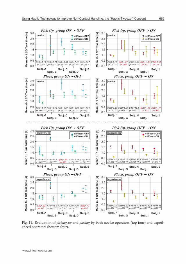
Fig. 11. Evaluation of picking up and placing by both novice operators (top four) and experi-enced operators (bottom four).
www.intechopen.com
Advances in Haptics666
Experienced Subjects
"Stuck" &
"Fell Off" Failure
Total Failure
"Stuck" &
"Fell Off" Failure
Total Failure
Mea
n +/
- 1 S
D F
ailu
re R
ate
[%] PlacePick Up
Novice SubjectsPlacePick Up
0
10
20
30
50
40
Mea
n +/
- 1 S
D F
ailu
re R
ate
[%]
0
10
20
30
50
40
"Stuck" &
"Fell Off" Failure
Total Failure
"Stuck" &
"Fell Off" Failure
Total Failure
t(9)=1.72p=.120
t(9)=2.91p=.017 *
t(9)=1.59p=.146
t(9)=.50p=.631
t(9)=1.48p=.174
t(9)=1.68p=.127
t(9)=2.37p=.042 *
t(9)=1.36p=.207
stiffness OFFstiffness ON
&&
stiffness OFFstiffness ON
&&
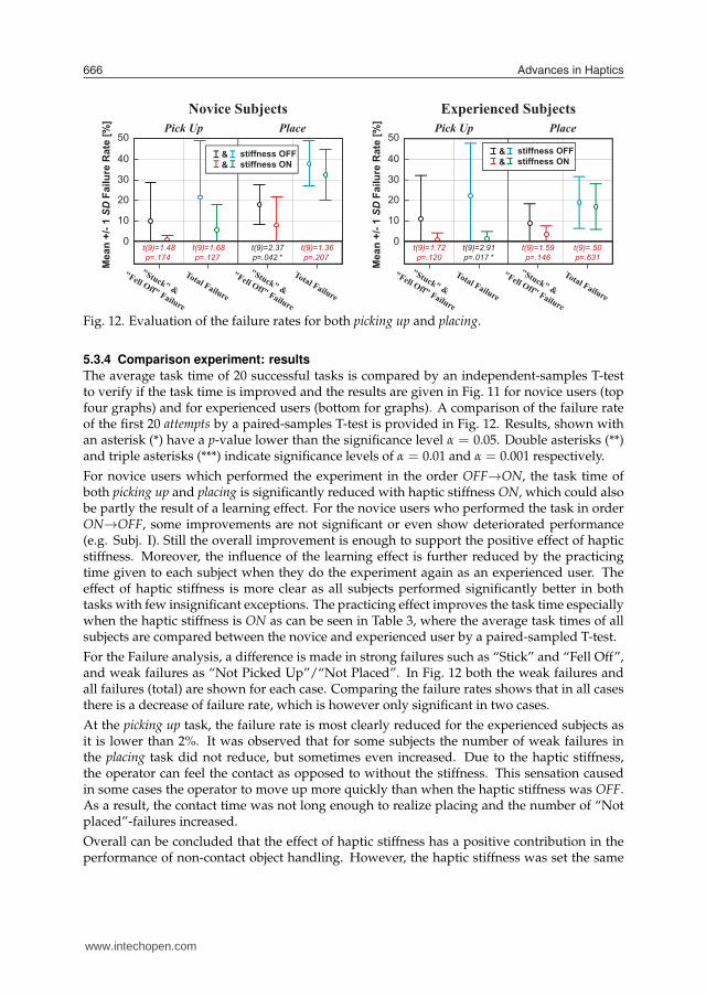
Fig. 12. Evaluation of the failure rates for both picking up and placing.
5.3.4 Comparison experiment: results
The average task time of 20 successful tasks is compared by an independent-samples T-testto verify if the task time is improved and the results are given in Fig. 11 for novice users (topfour graphs) and for experienced users (bottom for graphs). A comparison of the failure rateof the first 20 attempts by a paired-samples T-test is provided in Fig. 12. Results, shown withan asterisk (*) have a p-value lower than the significance level α = 0.05. Double asterisks (**)and triple asterisks (***) indicate significance levels of α = 0.01 and α = 0.001 respectively.
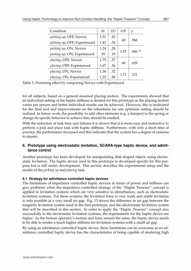
For novice users which performed the experiment in the order OFF→ON, the task time ofboth picking up and placing is significantly reduced with haptic stiffness ON, which could alsobe partly the result of a learning effect. For the novice users who performed the task in orderON→OFF, some improvements are not significant or even show deteriorated performance(e.g. Subj. I). Still the overall improvement is enough to support the positive effect of hapticstiffness. Moreover, the influence of the learning effect is further reduced by the practicingtime given to each subject when they do the experiment again as an experienced user. Theeffect of haptic stiffness is more clear as all subjects performed significantly better in bothtasks with few insignificant exceptions. The practicing effect improves the task time especiallywhen the haptic stiffness is ON as can be seen in Table 3, where the average task times of allsubjects are compared between the novice and experienced user by a paired-sampled T-test.
For the Failure analysis, a difference is made in strong failures such as “Stick” and “Fell Off”,and weak failures as “Not Picked Up”/“Not Placed”. In Fig. 12 both the weak failures andall failures (total) are shown for each case. Comparing the failure rates shows that in all casesthere is a decrease of failure rate, which is however only significant in two cases.
At the picking up task, the failure rate is most clearly reduced for the experienced subjects asit is lower than 2%. It was observed that for some subjects the number of weak failures inthe placing task did not reduce, but sometimes even increased. Due to the haptic stiffness,the operator can feel the contact as opposed to without the stiffness. This sensation causedin some cases the operator to move up more quickly than when the haptic stiffness was OFF.As a result, the contact time was not long enough to realize placing and the number of “Notplaced”-failures increased.
Overall can be concluded that the effect of haptic stiffness has a positive contribution in theperformance of non-contact object handling. However, the haptic stiffness was set the same
www.intechopen.com
Using Haptic Technology to Improve Non-Contact Handling: the “Haptic Tweezer” Concept 667
Experienced Subjects
"Stuck" &
"Fell Off" Failure
Total Failure
"Stuck" &
"Fell Off" Failure
Total Failure
Mea
n +/
- 1 S
D F
ailu
re R
ate
[%] PlacePick Up
Novice SubjectsPlacePick Up
0
10
20
30
50
40
Mea
n +/
- 1 S
D F
ailu
re R
ate
[%]
0
10
20
30
50
40
"Stuck" &
"Fell Off" Failure
Total Failure
"Stuck" &
"Fell Off" Failure
Total Failure
t(9)=1.72p=.120
t(9)=2.91p=.017 *
t(9)=1.59p=.146
t(9)=.50p=.631
t(9)=1.48p=.174
t(9)=1.68p=.127
t(9)=2.37p=.042 *
t(9)=1.36p=.207
stiffness OFFstiffness ON
&&
stiffness OFFstiffness ON
&&
Condition M SD t(9) p
picking up, OFF, Novice 1.51 .43
picking up, OFF, Experienced 1.42 .34.60 .566
picking up, ON, Novice 1.24 .28
picking up, ON, Experienced .95 .193.57 .006 **
placing, OFF, Novice 1.75 .57
placing, OFF, Experienced 1.67 .36.49 .639
placing, ON, Novice 1.38 .32
placing, ON, Experienced 1.23 .281.71 .121
Table 3. Practising effect by comparing Novice with Experienced
for all subjects, based on a general assumed placing motion. The experiments showed thatan individual setting of the haptic stiffness is desired for this prototype as the placing motionvaries per person and better individual results can be achieved. However, this is undesiredfor the final tool and improvements on the robustness for one optimum setting should berealized. In future work, the possibility to add other elements (e.g. a damper) to the spring orchange its specific behavior to achieve this, should be studied.
With the reduction of task time and failures it is shown that it is more easy and instinctive toperform a pick and place task with haptic stiffness. Furthermore, with only a short time ofpractice, the performance increased and this indicates that the system has a degree of easinessto master.
6. Prototype using electrostatic levitation, SCARA-type haptic device, and admit-
tance control
Another prototype has been developed for manipulating disk-shaped objects using electro-static levitation. The haptic device used in this prototype is developed specific for this pur-pose but is still under development. This section describes the experimental setup and theresults of the picking up and placing task.
6.1 Strategy for admittance controlled haptic devices
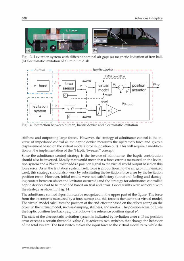
The limitations of impedance controlled haptic devices in terms of power and stiffness cangive problems when the impedance controlled strategy of the “Haptic Tweezer” concept isapplied to levitation systems which are very sensitive to disturbances, such as electrostaticlevitation systems. For these systems, the levitation force is very weak and stable levitationis only possible at a very small air gap. Fig. 13 shows the difference in air gap between themagnetic levitation system used in the first prototype, and the electrostatic levitation systemthat will be described in this section. In order to apply the “Haptic Tweezer” concept alsosuccessfully to the electrostatic levitation systems, the requirements for the haptic device arehigher. As the human operator’s motion and force remain the same, the haptic device needsto be able to render a much higher stiffness for levitation systems with a small air gap.
By using an admittance controlled haptic device, these limitations can be overcome as an ad-mittance controlled haptic device has the characteristics of being capable of rendering high
www.intechopen.com
Advances in Haptics668
350 µm
5.5 mm
(a) (b)
Fig. 13. Levitation system with different nominal air gap: (a) magnetic levitation of iron ball,(b) electrostatic levitation of aluminium disk
levitationsystem
forcesensorhand virtual
model
initial conditionswitch
switch
reset
reset
positionactuator
human haptic device
Fig. 14. Interaction between human, haptic device and electrostatic levitation
stiffness and outputting large forces. However, the strategy of admittance control is the in-verse of impedance control as the haptic device measures the operator’s force and gives adisplacement based on the virtual model (force in, position out). This will require a modifica-tion on the implementation of the “Haptic Tweezer” concept.
Since the admittance control strategy is the inverse of admittance, the haptic contributionshould also be inverted. Ideally that would mean that a force error is measured on the levita-tion system and a PI-controller adds a position signal to the virtual world output based on thisforce error. As in the levitation system itself, force is proportional to the air gap (in linearizedcase), this strategy should also work by substituting the levitation force error by the levitationposition error. However, initial results were not satisfactory (unnatural feeling and damag-ing contact between object and levitator occurred) and the strategy for admittance controlledhaptic devices had to be modified based on trial and error. Good results were achieved withthe strategy as shown in Fig. 14.
The admittance control algorithm can be recognized in the upper part of the figure. The forcefrom the operator is measured by a force sensor and this force is then sent to a virtual model.The virtual model calculates the position of the end-effector based on the effects acting on theobject in the virtual model, such as damping, stiffness, and inertia. The position actuator givesthe haptic position feedback phap that follows the reference position signal p∗.
The state of the electrostatic levitation system is indicated by levitation error ε. If the positionerror exceeds a certain threshold value C, it activates two switches that change the behaviorof the total system. The first switch makes the input force to the virtual model zero, while the
p
+
-
- -
-
+ +
+
steppingmotor
electrostaticlevitator
SCARAstructure
restraint
disk
laserproximity
sensor
forcesensor
electrodes
gapsensors
ballscrew
(b)
(b) (c)
www.intechopen.com
Using Haptic Technology to Improve Non-Contact Handling: the “Haptic Tweezer” Concept 669
350 µm
5.5 mm
(a) (b)
levitationsystem
forcesensorhand virtual
model
initial conditionswitch
switch
reset
reset
positionactuator
human haptic device
p
+
-
- -
-
+ +
+
steppingmotor
electrostaticlevitator
SCARAstructure
restraint
disk
laserproximity
sensor
forcesensor
electrodes
gapsensors
ballscrew
(b)
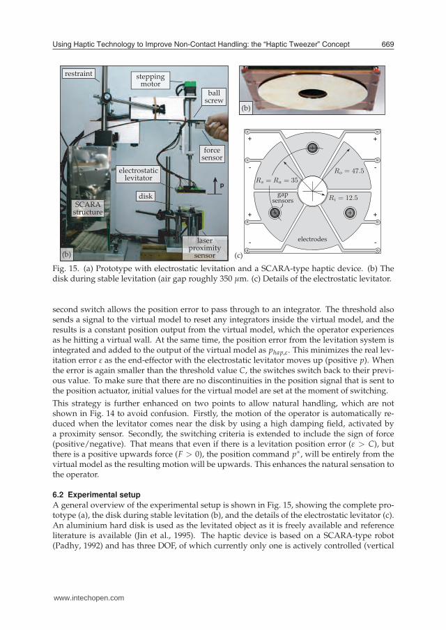
(b) (c)
Fig. 15. (a) Prototype with electrostatic levitation and a SCARA-type haptic device. (b) Thedisk during stable levitation (air gap roughly 350 µm. (c) Details of the electrostatic levitator.
second switch allows the position error to pass through to an integrator. The threshold alsosends a signal to the virtual model to reset any integrators inside the virtual model, and theresults is a constant position output from the virtual model, which the operator experiencesas he hitting a virtual wall. At the same time, the position error from the levitation system isintegrated and added to the output of the virtual model as phap,ε. This minimizes the real lev-itation error ε as the end-effector with the electrostatic levitator moves up (positive p). Whenthe error is again smaller than the threshold value C, the switches switch back to their previ-ous value. To make sure that there are no discontinuities in the position signal that is sent tothe position actuator, initial values for the virtual model are set at the moment of switching.
This strategy is further enhanced on two points to allow natural handling, which are notshown in Fig. 14 to avoid confusion. Firstly, the motion of the operator is automatically re-duced when the levitator comes near the disk by using a high damping field, activated bya proximity sensor. Secondly, the switching criteria is extended to include the sign of force(positive/negative). That means that even if there is a levitation position error (ε > C), butthere is a positive upwards force (F > 0), the position command p∗, will be entirely from thevirtual model as the resulting motion will be upwards. This enhances the natural sensation tothe operator.
6.2 Experimental setup
A general overview of the experimental setup is shown in Fig. 15, showing the complete pro-totype (a), the disk during stable levitation (b), and the details of the electrostatic levitator (c).An aluminium hard disk is used as the levitated object as it is freely available and referenceliterature is available (Jin et al., 1995). The haptic device is based on a SCARA-type robot(Padhy, 1992) and has three DOF, of which currently only one is actively controlled (vertical
www.intechopen.com
Advances in Haptics670
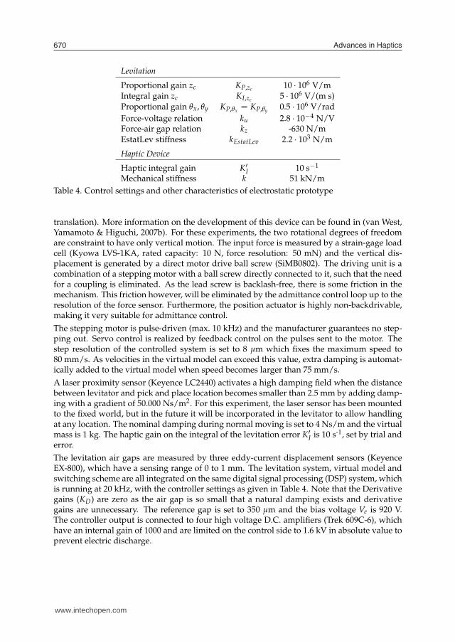
Levitation
Proportional gain zc KP,zc10 · 106 V/m
Integral gain zc KI,zc5 · 106 V/(m s)
Proportional gain θx, θy KP,θx= KP,θy
0.5 · 106 V/rad
Force-voltage relation ku 2.8 · 10−4 N/VForce-air gap relation kz -630 N/mEstatLev stiffness kEstatLev 2.2 · 103 N/m
Haptic Device
Haptic integral gain K′
I 10 s−1
Mechanical stiffness k 51 kN/m
Table 4. Control settings and other characteristics of electrostatic prototype
translation). More information on the development of this device can be found in (van West,Yamamoto & Higuchi, 2007b). For these experiments, the two rotational degrees of freedomare constraint to have only vertical motion. The input force is measured by a strain-gage loadcell (Kyowa LVS-1KA, rated capacity: 10 N, force resolution: 50 mN) and the vertical dis-placement is generated by a direct motor drive ball screw (SiMB0802). The driving unit is acombination of a stepping motor with a ball screw directly connected to it, such that the needfor a coupling is eliminated. As the lead screw is backlash-free, there is some friction in themechanism. This friction however, will be eliminated by the admittance control loop up to theresolution of the force sensor. Furthermore, the position actuator is highly non-backdrivable,making it very suitable for admittance control.
The stepping motor is pulse-driven (max. 10 kHz) and the manufacturer guarantees no step-ping out. Servo control is realized by feedback control on the pulses sent to the motor. Thestep resolution of the controlled system is set to 8 µm which fixes the maximum speed to80 mm/s. As velocities in the virtual model can exceed this value, extra damping is automat-ically added to the virtual model when speed becomes larger than 75 mm/s.
A laser proximity sensor (Keyence LC2440) activates a high damping field when the distancebetween levitator and pick and place location becomes smaller than 2.5 mm by adding damp-ing with a gradient of 50.000 Ns/m2. For this experiment, the laser sensor has been mountedto the fixed world, but in the future it will be incorporated in the levitator to allow handlingat any location. The nominal damping during normal moving is set to 4 Ns/m and the virtualmass is 1 kg. The haptic gain on the integral of the levitation error K′
I is 10 s-1, set by trial anderror.
The levitation air gaps are measured by three eddy-current displacement sensors (KeyenceEX-800), which have a sensing range of 0 to 1 mm. The levitation system, virtual model andswitching scheme are all integrated on the same digital signal processing (DSP) system, whichis running at 20 kHz, with the controller settings as given in Table 4. Note that the Derivativegains (KD) are zero as the air gap is so small that a natural damping exists and derivativegains are unnecessary. The reference gap is set to 350 µm and the bias voltage Ve is 920 V.The controller output is connected to four high voltage D.C. amplifiers (Trek 609C-6), whichhave an internal gain of 1000 and are limited on the control side to 1.6 kV in absolute value toprevent electric discharge.
www.intechopen.com
Using Haptic Technology to Improve Non-Contact Handling: the “Haptic Tweezer” Concept 671
6.3 Experimental results
The performance of this prototype is evaluated by performing a picking up and placing task.However, no comparison experiments are carried out as in fact it is nearly impossible for thehuman operator to hold the electrostatic levitator directly without losing the object, let aloneperforming a pick and place task. Performing the task with the haptic device, but without thehaptic effect is too dangerous because of the high forces the haptic device can provide.
6.3.1 Picking up
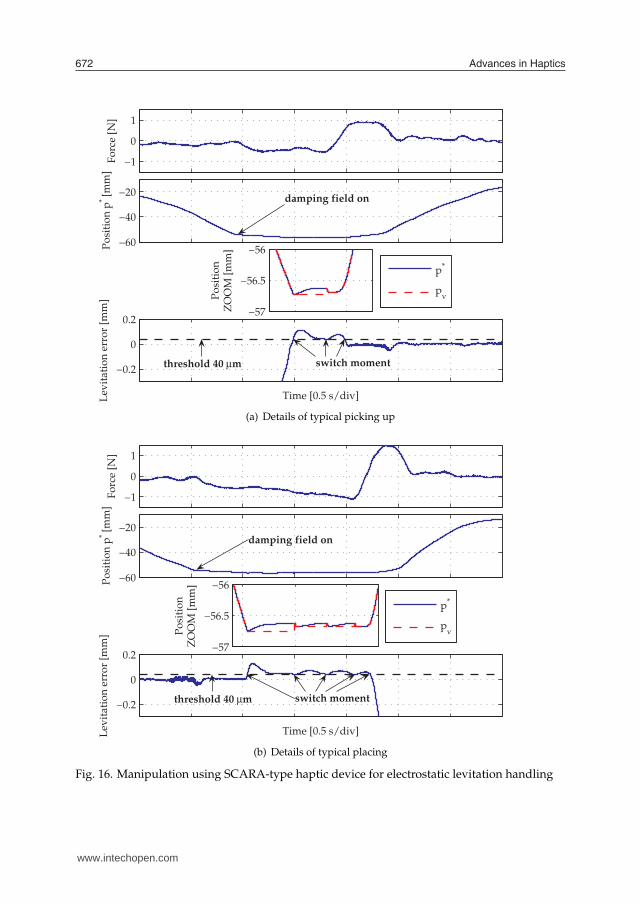
Details of a typical picking up task are shown in Fig. 16(a). The force exerted by the opera-tor on the haptic device (force sensor) is shown in the top. A negative force will result in adownwards motion until the disk is picked up and it is followed by a positive force to movelevitator and disk upwards. The motion that is sent to the position actuator (p∗) is shown inthe two middle plots. The change of speed, resulting from the high damping field is indicatedin the graph. To show the influence of the haptic contribution, which is the integral of levita-tion error to position signal p∗ at the switching moment, a zoomed plot of p∗ is given togetherwith the output from only the virtual model pv. The difference between the two plots is theadded integral of levitation error phap,ε. The levitation error itself is plotted in the lowest plottogether with the threshold value, such that the switching moments can be easily recognized.
The picking up task can be described in four steps. First, the operator moves down by applyinga downward force on the haptic device. Downward motion occurs and as soon as it comes insensing range of the laser sensing, the damping field slows down the motion. Second, the diskcomes in sensing range of the levitation gap sensors and will “jump” to the nominal levitationair gap of 350 µm (levitation error is zero). Due to the downward speed of the motion, almostdirectly after the levitating, the disk touches the support location again, creating a positive lev-itation error. The switch is activated and resultantly, the position p∗ is upwards even thoughthe operator’s force is still a negative. This is experienced by the operator as touching a wall.Finally, a positive force from the operator will result in the upwards motion and picking uphas been successful.
6.3.2 Placing
Details of a typical placing task are shown in Fig. 16(b), which follows the same structure asFig. 16(a), with the operator’s force on the top, the position signal in the middle, and thelevitation error on the bottom. The force and motion profile are very similar to the picking uptask. A negative force from the operator moves the levitated disk down and it is slowed downby the damping field upon detection by the laser sensor. The contact moment can be clearlyseen by looking at the levitation error as well as the switching moments that prevent the airgap to become too small. Multiple switching moments can be observed as in fact the operatoris still exerting a negative (downward) force. The positive force from the operator will movethe electrostatic levitator up, while the disk remains at the support location and placing hasbeen successful.
The actual release of the object is the result of the levitation controller wind up (not shown inthe figure) due to the integral gain KI as described earlier. The integrator reduces the attractiveforce as long as there is a positive levitation error. If this error persists for some time, thecontroller output is influenced in such a way, that even if the error is relieved, re-levitation isno longer possible (van West et al., 2008). With this strategy, placing becomes more easy as itis realized automatically.
www.intechopen.com
Advances in Haptics672
−1
0
1F
orc
e [N
]
−60
−40
−20
Po
siti
on
p* [
mm
]
−57
−56.5
−56
Po
siti
on
ZO
OM
[m
m]
p*
pv
−0.2
0
0.2
Lev
itat
ion
err
or
[mm
]
Time [0.5 s/div]
damping field on
threshold 40 µm switch moment
(a) Details of typical picking up
−1
0
1
Fo
rce
[N]
−60
−40
−20
Po
siti
on
p* [
mm
]
−57
−56.5
−56
Po
siti
on
ZO
OM
[m
m]
p*
pv
−0.2
0
0.2
Lev
itat
ion
err
or
[mm
]
Time [0.5 s/div]
damping field on
threshold 40 µm switch moment
(b) Details of typical placing
Fig. 16. Manipulation using SCARA-type haptic device for electrostatic levitation handling
www.intechopen.com
Using Haptic Technology to Improve Non-Contact Handling: the “Haptic Tweezer” Concept 673
7. Conclusion
This research has proposed the concept of “Haptic Tweezer,” which combines a haptic devicewith non-contact levitation techniques for intuitive and easy handling of contact-sensitive ob-jects by a human operator. The levitation error of the levitated object is used as an input forthe haptic device to minimize disturbances especially in the tasks of picking up and placing.The concept is evaluated by several prototypes of which two are described in this chapter, oneusing magnetic levitation and the haptic device PHANTOM Omni using an impedance con-trolled strategy, and a second prototype that uses electrostatic levitation and a SCRARA-typehaptic device using the admittance control strategy. Experiments with the first prototype haveshowed that significant improvements can be realized through the haptic feedback technol-ogy. Not only the failure rates were reduced, but the manipulation time was faster indicatingit is easier to perform the manipulation task with haptic assistance. The second prototypeshowed that the concept can also be successfully applied to handling objects with electrostaticlevitation, which is more sensitive to disturbances than magnetic levitation and also has amuch smaller levitation gap (350 µm). The haptic assistance makes it possible that a humanoperator can perform the tasks of picking up and placing of an aluminium disk which wouldnot have been possible without any haptic assistance. Both cases demonstrate the potential ofhaptic assistance for real-time assisting in performing tasks like non-contact manipulation.
8. References
Azuma, R., Baillot, Y., Behringer, R., Feiner, S., Julier, S. & MacIntyre, B. (2001). Recent ad-vances in augmented reality, IEEE Computer Graphics and Applications 21(6): 34 – 47.
Azuma, R. T. (1997). A survey of augmented reality, Presence: Teleoperators and Virtual Environ-ments 6(4): 355–385.
Bettini, A., Marayong, P., Lang, S., Okamura, A. M. & Hager, G. D. (2004). Vision-assistedcontrol for manipulation using virtual fixtures, IEEE Transactions on Robotics 20(6): 953– 966.
Bhushan, B. (2003). Adhesion and stiction: mechanisms, measurement techniques, andmethods for reduction, Journal of Vacuum Science & Technology B (Microelectronics andNanometer Structures) 21(6): 2262 – 96.
Earnshaw, S. (1842). On the nature of the molecular forces which regulate the constitution ofthe luminiferous ether, Trans. Camb. Phil. Soc. 7: 97–112.
Hayashibara, Y., Tanie, K., Arai, H. & Tokashiki, H. (1997). Development of power assistsystem with individual compensation ratios for gravity and dynamic load, Proc. IEEEInternational Conference on Intelligent Robots and Systems IROS97, pp. 640–646.
Jin, J., Higuchi, T. & Kanemoto, M. (1994). Electrostatic silicon wafer suspension, Fourth Inter-national Symposium on Magnetic Bearings, ETH Zurich, pp. 343 – 348.
Jin, J., Higuchi, T. & Kanemoto, M. (1995). Electrostatic levitator for hard disk media, IEEETransactions on Industrial Electronics 42(5): 467 – 73.
Kazerooni, H. (1996). The human power amplifier technology at the university of california,berkeley, Robotics and Autonomous Systems 19(2): 179 – 187.
Kazerooni, H. & Steger, R. (2006). The berkeley lower extremity exoskeleton, Journal of Dy-namic Systems, Measurement and Control, Transactions of the ASME 128(1): 14 – 25.
Lee, H.-K., Takubo, T., Arai, H. & Tanie, K. (2000). Control of mobile manipulators for powerassist systems, Journal of Robotic Systems 17(9): 469 – 77.
www.intechopen.com
Advances in Haptics674
Lin, H. C., Mills, K., Kazanzides, P., Hager, G. D., Marayong, P., Okamura, A. M. & Karam, R.(2006). Portability and applicability of virtual fixtures across medical and manufac-turing tasks, Proc. IEEE Int. Conf. Rob. Autom. ICRA06, Orlando, Florida.
Morishita, M. & Azukizawa, T. (1988). Zero power control of electromagnetic levitation sys-tem, Electrical Engineering in Japan 108(3): 111–120.
Nojima, T., Sekiguchi, D., Inami, M. & Tachi, S. (2002). The smarttool: A system for augmentedreality of haptics, Proc. Virtual Reality Annual International Symposium, Orlando, FL,pp. 67 – 72.
Padhy, S. (1992). On the dynamics of scara robot, Robotics and Autonomous Systems 10(1): 71 –78.
Peshkin, M., Colgate, J., Wannasuphoprasit, W., Moore, C., Gillespie, R. & Akella, P. (2001).Cobot architecture, IEEE Transactions on Robotics and Automation 17(4): 377 – 390.
Rollot, Y., Regnier, S. & Guinot, J.-C. (1999). Simulation of micro-manipulations: Adhesionforces and specific dynamic models, International Journal of Adhesion and Adhesives19(1): 35 – 48.
Rosenberg, L. B. (1993). Virtual fixtures: perceptual tools for telerobotic manipulation, IEEEVirtual Reality Annual International Symposium, Seattle, WA, USA, pp. 76 – 82.
Schweitzer, G., Bleuler, H. & Traxler, A. (1994). Active Magnetic Bearings, vdf HochschulverlagAG an der ETH Zürich.
Taylor, R., Jensen, P., Whitcomb, L., Barnes, A., Kumar, R., Stoianovici, D., Gupta, P., Wang,Z., deJuan, E. & Kavoussi, L. (1999). a steady-hand robotic system for microsurgicalaugmentation, International Journal of Robotics Research 18(12): 1201 – 1210.
van der Linde, R. & Lammertse, P. (2003). Hapticmaster - a generic force controlled robot forhuman interaction, Industrial Robot 30(6): 515–24.
van West, E., Yamamoto, A., Burns, B. & Higuchi, T. (2007). Non-contact handling of hard-diskmedia by human operator using electrostatic levitation and haptic device, Proceedingsof the 2007 IEEE/RSJ International Conference on Intelligent Robots and Systems IROS’07,San Diego, CA, USA, pp. 1106–11.
van West, E., Yamamoto, A. & Higuchi, T. (2007a). The concept of "haptic tweezer", a non-contact object handling system using levitation techniques and haptics, Mechatronics17(7): 345–356.
van West, E., Yamamoto, A. & Higuchi, T. (2007b). Development of scara-type haptic devicefor electrostatic non-contact handling system, Journal of Advanced Mechanical Design,Systems, and Manufacturing 2(2): 180–190.
van West, E., Yamamoto, A. & Higuchi, T. (2008). Automatic object release in magnetic andelectrostatic levitation systems, Precision Engineering 33: 217–228.
Woo, S. J., Jeon, J. U., Higuchi, T. & Jin, J. (1995). Electrostatic force analysis of electrostaticlevitation system, Proceedings of the 34th SICE Annual Conference, Hokkaido, Japan,pp. 1347–52.
www.intechopen.com

Advances in HapticsEdited by Mehrdad Hosseini Zadeh
ISBN 978-953-307-093-3Hard cover, 722 pagesPublisher InTechPublished online 01, April, 2010Published in print edition April, 2010
InTech EuropeUniversity Campus STeP Ri Slavka Krautzeka 83/A 51000 Rijeka, Croatia Phone: +385 (51) 770 447 Fax: +385 (51) 686 166www.intechopen.com
InTech ChinaUnit 405, Office Block, Hotel Equatorial Shanghai No.65, Yan An Road (West), Shanghai, 200040, China
Phone: +86-21-62489820 Fax: +86-21-62489821
Haptic interfaces are divided into two main categories: force feedback and tactile. Force feedback interfacesare used to explore and modify remote/virtual objects in three physical dimensions in applications includingcomputer-aided design, computer-assisted surgery, and computer-aided assembly. Tactile interfaces deal withsurface properties such as roughness, smoothness, and temperature. Haptic research is intrinsically multi-disciplinary, incorporating computer science/engineering, control, robotics, psychophysics, and human motorcontrol. By extending the scope of research in haptics, advances can be achieved in existing applications suchas computer-aided design (CAD), tele-surgery, rehabilitation, scientific visualization, robot-assisted surgery,authentication, and graphical user interfaces (GUI), to name a few. Advances in Haptics presents a number ofrecent contributions to the field of haptics. Authors from around the world present the results of their researchon various issues in the field of haptics.
How to referenceIn order to correctly reference this scholarly work, feel free to copy and paste the following:
Ewoud van West, Akio Yamamoto and Toshiro Higuchi (2010). Using Haptic Technology to Improve Non-Contact Handling: the “Haptic Tweezer” Concept, Advances in Haptics, Mehrdad Hosseini Zadeh (Ed.), ISBN:978-953-307-093-3, InTech, Available from: http://www.intechopen.com/books/advances-in-haptics/using-haptic-technology-to-improve-non-contact-handling-the-haptic-tweezer-concept