using failure injection mechanisms to experiment and … · 2016-12-27 · using failure injection...
TRANSCRIPT

Using failure injection mechanisms to experiment and
evaluate a hierarchical failure detector
Sebastien Monnet, Marin Bertier
To cite this version:
Sebastien Monnet, Marin Bertier. Using failure injection mechanisms to experiment and eval-uate a hierarchical failure detector. [Research Report] RR-5811, INRIA. 2006, pp.19. <inria-00070213>
HAL Id: inria-00070213
https://hal.inria.fr/inria-00070213
Submitted on 19 May 2006
HAL is a multi-disciplinary open accessarchive for the deposit and dissemination of sci-entific research documents, whether they are pub-lished or not. The documents may come fromteaching and research institutions in France orabroad, or from public or private research centers.
L’archive ouverte pluridisciplinaire HAL, estdestinee au depot et a la diffusion de documentsscientifiques de niveau recherche, publies ou non,emanant des etablissements d’enseignement et derecherche francais ou etrangers, des laboratoirespublics ou prives.

ISS
N 0
249-
6399
ISR
N IN
RIA
/RR
--58
11--
FR
+E
NG
ap por t de r ech er ch e
INSTITUT NATIONAL DE RECHERCHE EN INFORMATIQUE ET EN AUTOMATIQUE
Using failure injection mechanisms toexperiment and evaluate a hierarchical failure
detector
Sébastien Monnet , Marin Bertier
N˚5811
Janvier 2006
Systèmes numériques


Using failure injection mechanisms to experiment and evaluate ahierarchical failure detector
Sébastien Monnet�, Marin Bertier
�
Systèmes numériquesProjet Paris
Rapport de recherche n˚5811 — Janvier 2006 — 19 pages
Abstract: Computing grids consist of a large-scale, highly-distributed hardware architecture, oftenbuilt in a hierarchical way, as cluster federations. At such scales, failures are no longer exceptions,but part of the normal behavior. When designing software for grids, developers have to take failuresinto account, in order to be able to provide a stable service. The fault-tolerance mechanisms needto be validated and evaluated. It is therefore crucial to make experiments at a large scale, withvarious volatility conditions, in order to measure the impact of failures on the whole system. Thispaper presents an experimental tool allowing the user to control the volatility conditions during apractical evaluation of fault-tolerant systems. The tool is based on failure-injection mechanisms. Weillustrate the usefulness of our tool through an evaluation of a failure detector specifically designedfor hierarchical grids.
Key-words: Failure injection, failure detection, performance evaluation, fault tolerance, gridcomputing.
(Résumé : tsvp)
�[email protected]�[email protected]
Unité de recherche INRIA RennesIRISA, Campus universitaire de Beaulieu, 35042 RENNES Cedex (France)
Téléphone : 02 99 84 71 00 - International : +33 2 99 84 71 00Télécopie : 02 99 84 71 71 - International : +33 2 99 84 71 71

Utilisation de mécanismes d’injection de fautes pour tester undétecteur hiérarchique de défaillances
Résumé : Les grilles de calcul consistent en une architecture matérielle distribuée à grande échelle.Elles sont souvent organisées de manière hiérarchique, par exemple une fédération de grappes decalculateurs. À une telle échelle, les défaillances ne sont plus des exceptions, mais font partie ducomportement normal du système. La conception d’un logiciel pour la grille, doit prendre en compteces défaillances pour fournir un service stable. Les mécanismes de tolérance aux défaillances sontpar nature complexes et coûteux, ils doivent donc être validés et évalués. Il est crucial de pouvoirexpérimenter à grande échelle un système soumis à différents scénarii de défaillances afin d’observeret d’évaluer son comportement. Ce papier présente un outil permettant d’introduire de la volatilitéau cours d’une expérimentation pour évaluer les mécanismes de tolérance aux défaillances. Nousillustrons son utilité à travers un exemple : l’évaluation d’un détecteur de défaillances conçu spéci-fiquement pour les grilles hiérarchiques.
Mots-clé : Injection de fautes, détection de fautes, évaluation de performances, tolérance aux fautes,grilles de calcul.

Failure injection & failure detection 3
1 Introduction
A current trend in high-performance computing is the use of large-scale computing grids. Theseplatforms consist of geographically distributed cluster federations gathering thousands of nodes.At this scale, node and network failures are no more exceptions, but belong to the normal systembehavior. In this context, applications must tolerate failures. This results in an extra difficulty whenimplementing and evaluating distributed applications.
To be able to evaluate a fault-tolerant application, it is essential to test how the application re-acts to failures. But such applications are often non deterministic and failures are not predictable.However, an extensive experimental evaluation requires execution reproducibility.
In this paper, we introduce a failure injection tool able to express and reproduce various failureinjection scenarios. This provides the ability to extensively evaluate fault-tolerance mechanismsused by distributed applications. As an illustration, we use this tool to evaluate a failure detectorservice adapted to the grid architecture [7]. A failure detector is a well-known basic building blockfor fault-tolerant distributed systems, since most fault-tolerance mechanisms require to be notifiedabout failures. These experiments are run over the Grid’5000 National French grid platform.
The remainder of this paper is composed as follows: Section 2 describes the context we assume(time and failure models). Section 3, describes and explains how to use our failure injection tool.Section 4 presents the failure detector we evaluate. Section 5 illustrates the usage of our failureinjection tool for a practical evaluation of the failure detector. Finally, Section 6 concludes thepaper.
2 System model
Globalnetwork
Local group (SAN) Local group (LAN)
Local group (SAN)
Figure 1: Hierarchical organization
In this paper, we suppose that the grid architecture of the system implies a hierarchical orga-nization (as illustrated by Figure 1). It consists of clusters of nodes with high-connectivity links,typically System Area Networks (SAN) or Local Area Networks (LAN), interconnected by a globalnetwork, such as Internet. In this context, we call local group each pool of processes running withinthe same SAN or LAN, and global network the network which connects the local groups.
RR n˚5811

4 Monnet & Bertier
Each local group is a finite set of processes that are spread throughout a local network. Thedistributed system is composed of a finite set of local groups. Every process communicates only bysending and receiving messages. All processes are assumed to have a preliminary knowledge of thesystem’s organization.
We rely on the model of partial synchrony proposed by Chandra and Toueg in [12]. This modelstipulates that, for every execution, there are bounds on process speeds and on message transmissiontimes. However, these bounds are not known and they only hold after some unknown time (calledGST for Global Stabilization Time). We assume that processes can fail following the fail-stop model:they run correctly until they fail, then they stop interacting with the other processes definitively. wealso assume a fair-lossy network. A communication link ����� is fair-lossy means that if � iscorrect and if process � sends an infinite number of messages � to process � , then � receives aninfinite number of messages � . The clocks are not synchronized but we assume the existence of aknown upper bound on the drift rate of local clocks.
This set of hypotheses fit the behavior of a typical computing grid: nodes crashes are possibleand messages may be dropped by routers during network congestion.
Note that the two levels of the grid hierarchy exhibit different properties for communications(latency, bandwidth, message loss rate).
3 Experimenting with various volatility conditions
3.1 Benefits of experimentation.
A theoretical evaluation of a system can be carried out using a formal proof of a system model,which can validate the system design. However, it relies on a formal model, which is generallya simplification of the reality (taking into account only significant parameters). A second type ofevaluation uses extensive simulations [9, 17, 11], which as formal proof, generally run models ofthe design and not the implementation itself. Finally, experimentations on real testbeds can serveas a proof of concept. Such a practical evaluation can capture aspects related, for instance, to thenode specifications or to specifics of the underlying physical network. In this paper we focus onexperimental evaluations.
Experimenting large-scale distributed software is difficult. The tests have to be deployed andlaunched on thousands of geographically distributed nodes, then the results have to be collectedand analyzed. Besides, the tests have to be reproducible. Achieving these tasks for a large-scaleenvironment is not a trivial task.
3.2 Controlling volatility
In the context of large-scale, fault-tolerant distributed systems, one important aspect which needsto be controlled is node volatility. This section introduces a tool that provides the ability to injectfailures during experiments, in order to evaluate the quality of fault-tolerance mechanisms. Morespecifically, we illustrate how such a tool can be used in order to test a failure-detection service.
INRIA

Failure injection & failure detection 5
3.2.1 Failure injection requirements.
One way of testing fault-tolerant mechanisms with different volatility conditions is to use failureinjection mechanisms. This may validate that the service provided by the software is still avail-able when particular types of failures occur. It also provides the avability to measure the overheadintroduced by the fault-tolerant mechanism to support different kinds of failures.
The experimentations are run on a testbed that is assumed to be stable. As we want to experimentwith controlled failures, we assume that there are no other unexpected failures during the test (incase of a real failure, the developer will have to re-launch his test). The test tool can help thedeveloper to introduce controlled failures during the experimentation. In order to emulate somespecific scenarios and to be scalable, the test tool has to provide a simple and efficient way to describefailures distributed across thousands of nodes.
The failure injection mechanisms should be able to take only statistical parameters and thencompute failure schedules accordingly. This allows the tester to generate a failure scenario acrossthousands of nodes by giving only a few parameters. The failure injection mechanisms also needto be highly customizable allowing the user to specify groups of nodes that should fail simultane-ously. More generally, they need to provide the availability to express failure dependencies betweennodes. This should allow the tester to emulate correlated failures. Furthermore, the developer shouldhave the possibility to specify parameters for particular nodes in order to play the role of the “en-emy”. Last, an important feature of a failure injector (volatility controller) is reproducibility. Evenif failures are computed using statistical parameters, one may want to replay an execution with thesame set of failures, while varying other parameters (e.g. in order to tune the fault-tolerance algo-rithms). While experimenting various parameters of a fault tolerance feature or testing different faulttolerance mechanisms one may want to compare different solutions within the same context.
3.2.2 Scenarios.
Simple failure scheme. One simple way to describe a failure scheme is to assume that all thenodes have the same probability of failure and that they are independent (i.e the failure of a particularnode does not depend on the failure of other ones). For instance, one may assume that the MTBF(Mean Time Between Failures) of a particular set of nodes may be one hour. The MTBF of a specificarchitecture can be easily observed. The developer may wish to run experiments with smaller MTBFvalues in order to stress the fault-tolerant mechanisms.
Correlated failures. As the underlying physical network system may be very complex, with hubsand switches, some failures may induce new ones. The crashes of some nodes may lead to thecrashes of other nodes. By instance, while running a software on a cluster federation, a wholecluster may crash (Figure 2). This may be due to a power failure in one cluster room, for instance.While designing a fault-tolerant system for such an architecture, it is important to experiment itsbehavior while multiple failures occurs concurrently as it may happen in real executions (withoutfailure injection mechanisms).
RR n˚5811

6 Monnet & Bertier
Globalnetwork
Power failure
Standard nodeManager node
Figure 2: Different kinds of failures
Accurate control. As the roles played by the different nodes in the system may not be strictlyequivalent (some are more critical than others), the developer should be able to test some particularcases. For instance, one may want to experiment the simultaneous crash of two particular nodes, orthe crash of a node when it is in a particular state (Figure 2). Typically, experimenting the failureof a node having manager capabilities may be really interesting as it may involve particular cases ofthe fault-tolerant algorithms.
3.3 Related work
Researchers working in the fault-tolerance area need to inject failures during their experiments.Most often this is done in an ad-hoc manner, by manually killing nodes or by introducing a few codestatements into the tested system’s source code, to make failures occur. The overhead for the testeris non negligible and usually it is neither scalable nor reproducible. The goal of our failure injectionmechanism is precisely to automate this task, making it easy for the testers to inject failures at largescale and to control volatility conditions.
Many research efforts focus on failure injection. However, most of them are very theoretical orfocus on the problem of failure prediction [20, 19, 6]. In this paper we do not address the issue ofwhen a failure should be injected or what it will induce, but we provide a practical solution to how toinject it. The tester may use the results of these previous research works to feed our failure injectors.
Failure injection has also been studied for simulation and emulation. For instance, [3] providesa solution to test protocols under failure injection, but it relies on a fully centralized approach.Our work is intended to be used for tests running on real distributed architectures, with the fullapplication code.
INRIA

Failure injection & failure detection 7
(00) <network analyze-class="test.Analyze">(01) <profile name="manager" replicas="1">(02) <!-- peer information -->(03) <peer base-name="peerA"/>...(11) <bootstrap class="test.MyClass1"/>(12) <!-- argument -->(13) <arg value="x"/>(14) </profile>(15) <profile name="non-manager" replicas="20">(16) <peer base-name="peerB"/>...(23) <bootstrap class="test.MyClass2"/>(24) </profile>(25) </network>
Figure 3: Example of JDF’s XML description file
FAIL [14] (FAult Injection Language) defines a smart way to define failures scenarios. It relieson a compiler to trap application communications to emulate failures. Our work is integrated in thetest environment, not at application level, thus it allows to inject failures even when the source codeis unavailable.
In contrast to previous work, we use failure mechanisms within a test tool, providing a simpleway to deploy, run and fetch results of a test under various controlled volatility conditions.
3.4 Failure injectors
3.4.1 JXTA Distributed Framework (JDF).
We are currently developing our failure injection mechanism within the JXTA Deployment Frame-work (JDF [21, 4]) tool. The JDF project has been initiated by Sun Microsystems, and is currentlybeing actively developed within the PARIS Research Group [1]. JDF is a tool designed to automatethe tests of JXTA-based systems. In [4] we have specified that this kind of tool should provide theability to control the simulation of nodes’ volatility. In the remaining of this section we show howto provide this ability inside JDF. A detailed description of JDF can be found in [21].
3.4.2 JDF description language extension.
The first requirement to fulfill in order to use failure injection is to incorporate failure information isinto the JDF test description language
JDF allows the user to describe his test through 3 configuration files. 1) a node file containingthe list of nodes on which the test is run, 2) a file storing the names and paths of the files to deploy oneach node, and 3) a XML file describing the node profiles, in particular, the Java classes associatedand the parameters given to these classes.
JDF’s XML description file allows the tester to describe his whole system through profiles.Figure 3 defines 2 profiles, one from line 01 to 14 and one from line 15 to 24. Then multiple nodescan share a same profile. The profile named non-manager on Figure 3 is replicated on 20 differentnodes (thanks to the replicas attribute).
RR n˚5811

8 Monnet & Bertier
The first experimentation phase consists of the creation of these files. This phase is called basicconfiguration thereafter.
To provide the ability to express failures dependencies (to represent correlated failures) we adda new XML tag: failure. This tag may have 2 attributes: 1) grp to indicate that all nodes havingthis profile are part of a same failure group; 2) dep to indicate that nodes having this profile depend,from a failure point of view, on nodes of another profile. The grp attribute allows to specify groupsof nodes that should fail together (i.e. if one of them crashes, then all the set crashes). This can helpthe tester simulate the failure of clusters, for instance. The dep attribute can be used to indicate thata node should crash if another one crashes (by instance to emulate the fact that the second node mayserve as a gateway for the first one).
The nodes having a profile containing the following failure tag will crash as soon as a nodebelonging to failure group 1 crashes.
<failure grp="1"/>
If one node having the profile named profileName crashes, then all nodes which profile containsthe following tag crash.
<failure dep="1"/>
3.4.3 Computing the failure Schedule.
We have developed a tool that generates a configuration file with various volatility-related param-eters (e.g. the global MTBF) which are given as an input to JDF. To do this, we introduce a newconfiguration file. In order to make the failure conditions reproducible, this file contains the uptimesfor all nodes (i.e. the failure schedule). It is generated using the XML description file, which isnecessary in order to take into account failure dependencies. This phase is called failure schedulegeneration thereafter.
The tool works as follows: it computes the first date using a given MTBF and the number ofnodes (obtained by parsing the XML description file), then it randomly and uniformly chooses anode to which it assigns this first failure date. This operation is repeated until a failure date isassign to each node. Next, dependency trees are built using the information contained in the XMLdescription file. The dependency trees are used to ensure that 1) in each failure group, nodes areassigned the smallest failure date of the group; 2) if the failure date of a node is greater than thefailure date of a node on which it depends (the dep attribute), then the smallest date is assigned. Thisway, all dependencies expressed in the XML description file are satisfied.
Computing the failure schedule statically before launching the test allows the tester to easilyreproduce failure conditions. To run multiple tests with the same failure conditions, the tool islaunched once to compute a failure schedule, and the same computed schedule will be used by themultiple experiments.
INRIA

Failure injection & failure detection 9
3.4.4 Running experiments with failure injection.
Assuming that the standard JDF configuration files exist (i.e. the basic configuration phase has beendone), the complexity overhead induced by the failure injection mechanisms to launch tests is verylow.
To run a test by providing a MTBF value (Simple failure scheme) the tester has to launch a JDFscript that will compute the failure dates before running his test as shown by Figure 4. This means
ExecutionBasic configuration Failure schedule generation
Figure 4: Simple failure scheme
that the failure schedule generation phase consist in executing a script with the desired MTBF valueand the JDF standard configuration files.
As a further step, to use correlated failures, the tester needs to use our JDF description languageextension. In this case, one Failure configuration phase is required to add failure tags in the XMLconfiguration file to (Figure 5).
Basic configuration
Configuration
Failure configuration
Execution
Failure schedule generation
Figure 5: Correlated failures
Finally, the tester may need an accurate control of the failures (i.e inject a failure on a specificnode at a specific time). To do this, the failure schedule has to be edited by providing peer identifiersand the corresponding failure dates.(Figure 6).
Basic configuration
Configuration
Failure configuration Failure schedule generation
Execution
Failure schedule refinement
Figure 6: Accurate control
As illustrated by Figure 7, once the schedule is computed no extra step is needed to re-executean experiment with the same failure conditions (event if the used physical nodes change).
3.4.5 Run time failure injection.
At deployment time, a configuration file containing the failure schedule is sent to each node. Asshown on Figure 8, at launch time, a killer thread is started. This thread reads the failure date (which
RR n˚5811

10 Monnet & Bertier
Basic configuration
Configuration
Failure configuration Failure schedule generation
Execution
Failure schedule refinement
Figure 7: Reproducibility
New Killer().start()
Main flow(test class)
configuration file
read
KillerThread
System.exit()Time out
Figure 8: Failure injection
is actually an uptime), then waits accordingly. If the application is still running at the failure date,this thread kills it, thereby emulating a failure.
Note that all the application threads are killed, but the physical node itself remains up and run-ning. If an application uses the TCP protocol, the node will answer immediately that no process iscurrently listening to this port. If the node were really down, the application would have to wait for aTCP time-out. In the case of the UDP protocol (as for the experiments presented in this paper), thisside-effect does not exist. For applications using the TCP protocol, the thread killer should eithertrap messages or really shutdown the network interface.
INRIA

Failure injection & failure detection 11
4 A scalable failure detection service
We used the failure injection mechanisms previously described to evaluate a scalable failure detectoradapted to hierarchical grids. This section introduces the failure detector. The next section willpresent the evaluation results.
4.1 Unreliable failure detectors
4.1.1 Concepts.
Since their introduction by Chandra and Toueg in [12], failure detectors are becoming a basic build-ing block for fault-tolerant systems. A failure detector is one solution to circumvent the impossibility[15] of solving deterministically the consensus in asynchronous systems in presence of failure.
The aim of a failure detectors is to provide information about the liveness of other processes.Each process has access to a local failure detector which maintains a list of processes that it currentlysuspects of having crashed. Since a failure detector is unreliable, it may erroneously add to its lista process which is still running. But if the detector later realizes that suspecting this process isa mistake, it then removes the process from its list. Failure detectors are characterized by twoproperties: completeness and accuracy. Completeness characterizes the failure detector capabilityof suspecting incorrect process permanently. Accuracy characterizes the failure detector capabilityof not suspecting correct processes.
We focus on the ��� detector, named Eventually Perfect, it is one of failure detector classes,which enable to solve the consensus problem (i.e. it is not the weakest). This detector requires thefollowing characteristics:
� Strong completeness: there is a time after which every process that crashes is permanentlysuspected by every correct process.
� Eventual strong accuracy: there is a time after which correct processes are not suspected byany correct process.
4.1.2 Utility.
A failure detector ��� provides the ability to solve the consensus, but it does not contradict theimpossibility of Fischer, Lynch and Paterson, then it is impossible to implement it in asynchronoussystems.
A failure detector has several advantages from a theoretical and a practical point of view. Thefirst one is to abstract synchronism matter: algorithms that use a failure detector depends on failureonly. The hypotheses, in terms of completeness and accuracy, describe how a failure detector detectsother processes failures. These hypotheses are more natural than temporal ones but also useful.
In a practical way, the need to detect failures is a common denominator among the majorityof distributed reliable applications. In fact an application must know if one of these processes hascrashed: to be able to replace it in case of replication or more generally to avoid waiting infinitelyits result. From this perspective, a failure detector is a specific service which provides the ability to
RR n˚5811

12 Monnet & Bertier
guarantee the application vivacity. This service can be shared by several applications and then itscost is amortized.
4.2 GFD (GRID Failure Detector)
4.2.1 Properties.
The aim of our failure detector is to propose a shared and moreover scalable detection service amongseveral applications. In this implementation we dissociate two aspects: a basic layer which computesan estimation of the expected arrival date to provide a short detection time and an adaptation layerspecific for each application. This adaptation layer guarantees the adequacy between the detectionquality of service and the application needs. This architecture provides the ability to generate onlyone flow of messages to provide adapted detection information for all applications.
The second specificity is the hierarchical organization of the detection service in order to de-crease the number of messages and the processor load [8]. It comprises two levels: a local and aglobal one, mapped upon the network topology. The system is composed of local groups, mappedupon SANs or LANs, bound together by a global group. Each group is a detection space: everygroup member watches all the other members of its group. Every local group designates at least onemandatory which will participate to the global group.
This organization implies two different failure detector types. This distinction is important sincea failure does not have the same interpretation in the local context as in the global one. A local failurecorresponds to the crash of a host, whereas in the global context a failure represents the crash of anentire local group. In this situation, the ability to provide different qualities of service to the localand the global detectors is a major asset of our implementation. Therefore a local group mandatoryhas two different failure detectors, one for the local group and one for global group.
In a local group, the failure detector uses IP-Multicast for sending “I am alive” messages. InSANs and LANs, IP-Multicast can be used with the broadcast property. Therefore a host only sendsone message to communicate with all the other hosts. Failure detectors in a global group use UDPin order to be more compatible with the general network security policy.
4.2.2 Implementation technique.
They are several possible implementations for failure detectors, but all of these suppose a constantflow of message. In our implementation [7], we use a technique called heartbeat.� sends periodically an “I am alive” message ����� ���������� to the processes in charge of detecting
its failure. To determine whether to suspect � , � uses a sequence ������������� of fixed time units calledfreshness points. If the message �� is not arrived at the time � then � starts to suspect � . If � laterreceives an “I am alive” message from � , � removes � from its list of suspected processes (see Figure9). In our implementation, ������ ��� is composed of an expected arrival date ( ��������� ��� ) and a safetymargin ( ������� ��� ) computed dynamically for each message. The safety margin is calculated similarlyto Jacoson’s estimation [16].
����� ���"! ���#����� ���%$ ������� ���
INRIA

Failure injection & failure detection 13
��������� ��� � ! � ��� ����#��� �%$ ��� ��� ��� ���
��� ��� ����� ��� ! ��� ��� ��� � $�� � ��������� ��� ������ ����� ��� ! ����� ��� � $�� � ��� ��������� ��� � � � ����� ��� ���������� ��� ! ��� ��� ����� ��� $� � ����� ����� ���
Process p
Process q
Freshness points: τ i−1 τ τ τi i+1 i+2
h h h hi−1 i i+1 i+2
FD at q
i
AiA A i+1i−1
Figure 9: Failure detection with the heartbeat strategy
Where � is the receipt times of the message � . The expected arrival date ( ��������� ��� ) is anaverage of � last arrival dates. This estimation is inspired by Chen estimation [13]. If at least �messages have been received, ��� can be computes with:
���#����� ���"! ���#��� �%$���� � � �#������� � �����
5 Experimentations
5.1 Experimental setup.
For all the experiments, we used the Grid’5000 platform [2], which gathers 9 clusters geographicallydistributed in France. These clusters are connected together through the Renater Education andResearch National Network (1 Gb/s). For our preliminary experiments, we used 16 nodes in 4 ofthese sites (Rennes, Lyon, Grenoble and Sophia), for a total of 64 nodes. In these 4 sites, nodes areconnected through a gigabit Ethernet network (1 Gb/s).
This platform is hierarchical in terms of latency: a few milliseconds among the clusters, around0.05 within each cluster (the precise values are given on Table 5.1).
From ! To Rennes Grenoble Sophia LyonRennes 0.042 10.2 9.0 8.2
Grenoble 0.05 2.72 2.4Sophia 0.039 4.93Lyon 0.029
Table 1: Latencies matrix (in ms)
RR n˚5811
14 Monnet & Bertier
As our failure detector is hierarchical, with a local and a global level, the 64 nodes are partitionedinto 4 local groups, one in each cluster. Within each local group, a special node (mandatory) isresponsible for the failure detection at global level (i.e cluster failures).
Even if our algorithms do not require a global clock assumption, for measurements purposes, weassume a global clock. Each node runs a ntp (network time protocol) client to synchronize its localclock and we assume that the local clock drifts are negligible (as the test period is short, of the orderof a few tens of minutes). This assumption stands only for measurements purposes.
5.2 Performance metrics
The most important parameter of the failure detector is the delay between heartbeats. It defines thetime between two successive emissions of an “I am alive” message. The parameters of the expectedarrival date calculation are the same for each experiment:
� the number of messages taken into account for the computation of ��� : � ! �������,
� the weight of the last value in the computation of � : � ! � � � ,� the weight of the variance ����� in the computation of � : ��! �
.
The failure injection is essentially characterized by the MTBF: Mean Time Between Failure andpossibly by the correlation between failures described in the test files.
The experimental results are essentially expressed in terms of detection latency. It correspondsto the elapsed time between a node crash and the moment when the other nodes start suspecting itpermanently.
5.3 Preliminary tests.
We started by evaluating the failure injection mechanisms alone. The goal is to assess its abilityto inject failures according to a given MTBF following an exponential distribution. To do this, welaunch 20 times a test with a MTBF value set to one minute, with no failure dependencies. Beforeeach test, the failure schedule is recomputed in order to obtain mean failure dates. Figure 10 showsthat the average number of alive nodes decrease as the time elapses. The experimental results areclose to the theoretical ones obtained using an exponential distribution.
In a second experiment, we evaluated the ability of our failure injector to correctly generatecorrelated failures. There again we assume the failures follow the same exponential distribution.Besides, we add a failure dependency: all members of local group 1 (located in Rennes) depend ontheir mandatory (i.e. they must fail if the mandatory fails). This results in a gap on Figure 11 whenRennes’ mandatory is killed, as all nodes in Rennes fail concurrently. After this correlated failurehappens, the slope of the curve is smaller. This is due to the fact that the dependency made somefailures happen sooner.
We can conclude that the failure injector is able to inject failures according to a given MTBF andmay also take into account correlated failures.
INRIA

Failure injection & failure detection 15
40
45
50
55
60
65
0 5 10 15 20 25 30
Num
ber
of n
odes
Time (min)
Experimental resultsTheoretical results
Figure 10: Failure injection according to MTBF
30
35
40
45
50
55
60
65
0 5 10 15 20 25 30
Num
ber
of n
odes
Time (min)
Number of nodes
Figure 11: Correlated failures
RR n˚5811

16 Monnet & Bertier
200
400
600
800
1000
1200
1400
1600
500 1000 1500 2000 2500 3000
Det
ectio
n la
tenc
y (m
s)
Delay between heartbeats (ms)
Local detection times
Figure 12: Local detection times
5.4 Experimenting with the failure detector
5.4.1 Tradeoff: detection time versus network stress.
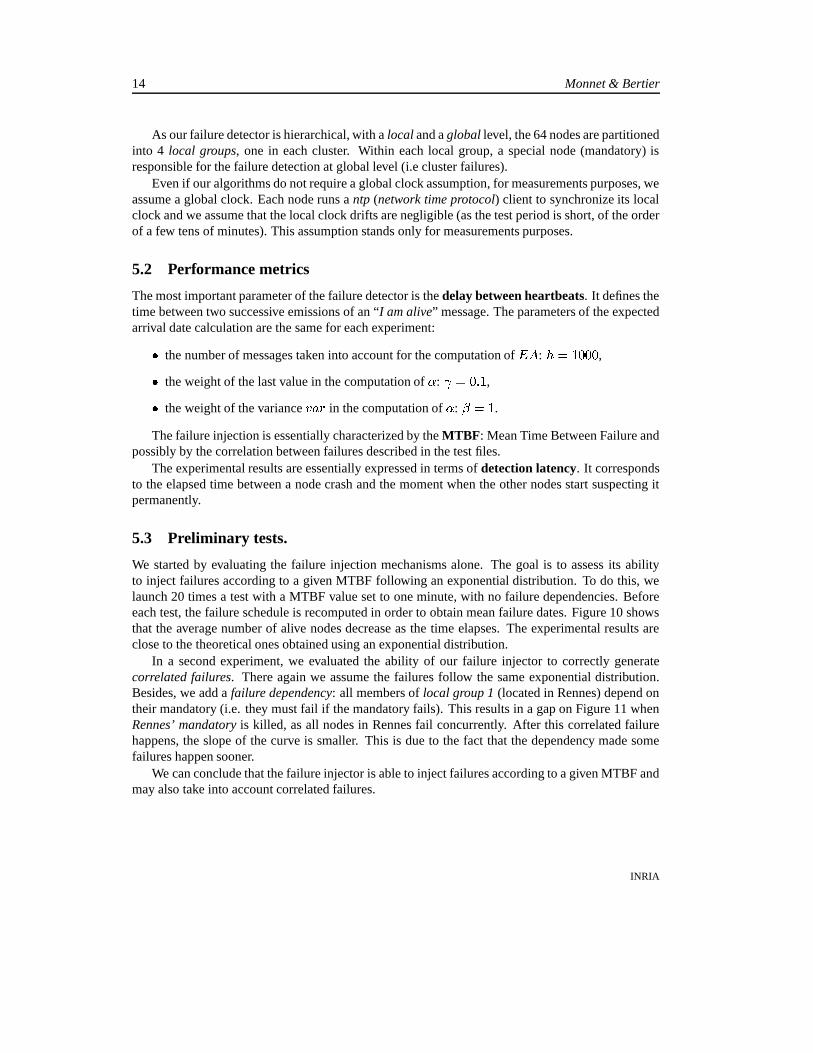
The failure detector is hierarchical: it provides failure detection in local groups (i.e clusters) andbetween these groups. We first evaluate the detection time at local level (within local groups) ac-cording to the delay between heartbeats of the failure detector. To do this evaluation, we set a MTBFof 30 seconds with no failure dependency, and no mandatory failures. During each run of 10 min-utes, 18 nodes are killed. Figure 12 shows for each delay between heartbeats the average failuredetection time in local groups. The results are very close to what we expected: theoretically, theaverage detection time is
� ��� ��� _ � ����� ����� _ � ������� � ������� � � $ � ��������� � (and the maximum detectiontime is almost
� ��� ��� _ � ����� ����� _ � ������� � ������ �%$ � ��������� � ). On the other hand, as the delay betweenheartbeats decreases, the number of messages increases, as shown by figure 13. For a fixed accuracyof the failure detection, there is a tradeoff between detection time and network stress. This is why,through adapters, our failure detector allows multiple applications to share the same heartbeat flowto minimize the network load.
5.4.2 Correlated failures.
The aim of this second experiment is to evaluate the detection time at the global level. At this level,the failure detection is done through the local group mandatories. When the failure of a mandatoryis detected in a group, a new one is designated to replace it with an average nomination delay of156ms. Thus, to experiment failure detection at global level, we need to use correlated failures inorder to induce the crash of whole local groups. We emulate the failure of sites by introducing afailure dependency between the members of a group (i.e nodes in one site) and their mandatory. Byinstance, for the Rennes cluster, we add:
<failure dep="RennesMandatory"/>
INRIA
Failure injection & failure detection 17
200
400
600
800
1000
1200
1400
1600
1800
500 1000 1500 2000 2500 3000
Num
ber
of r
ecei
ved
mes
sage
s pe
r m
inut
e
Delay between heartbeats (ms)
Number of received messages
Figure 13: Network stress
200
400
600
800
1000
1200
1400
1600
1800
500 1000 1500 2000 2500 3000
Det
ectio
n la
tenc
y (m
s)
Delay between heartbeats (ms)
Global detection times
Figure 14: Global detection times
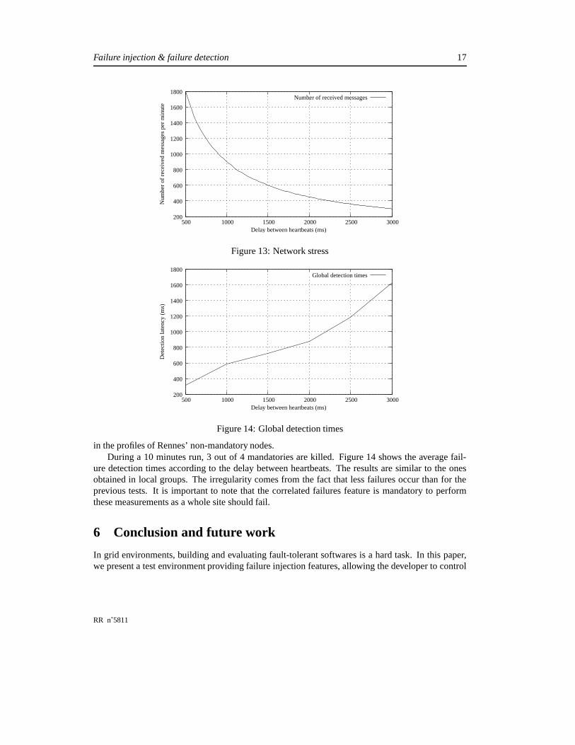
in the profiles of Rennes’ non-mandatory nodes.During a 10 minutes run, 3 out of 4 mandatories are killed. Figure 14 shows the average fail-
ure detection times according to the delay between heartbeats. The results are similar to the onesobtained in local groups. The irregularity comes from the fact that less failures occur than for theprevious tests. It is important to note that the correlated failures feature is mandatory to performthese measurements as a whole site should fail.
6 Conclusion and future work
In grid environments, building and evaluating fault-tolerant softwares is a hard task. In this paper,we present a test environment providing failure injection features, allowing the developer to control
RR n˚5811

18 Monnet & Bertier
volatility without altering the application code. To illustrate this tool, we evaluate a hierarchicalfailure detection service. First, our experiments have show that our failure injection tool is able toprovide accurate volatility control in a reproducible manner. This allowed us to evaluate a hierar-chical failure detection service by emulating independent and correlated failures. In each of thesetwo cases, we have run multiple experiments for different configurations of the failure detector. Theresults show that the faults are efficiently detected. To the best of our knowledge, no failure detectorshave been experimented in the past using automated failure injection on grid platforms.
We plan to further enhance our test environment by adding support for message loss injection.This can be done through network emulation tools like Dummynet [18] or NIST Net [10]. The failuredescription language will be extended accordingly, in order to incorporate message loss description.Furthermore we will use this test environment to evaluate the fault tolerance mechanisms of higher-level grid service (e.g. the JUXMEM [5] data sharing service).
References
[1] The PARIS research group. http://www.irisa.fr/paris.
[2] Projet Grid’5000. http://www.grid5000.org.
[3] Guillermo A. Alvarez and Flaviu Cristian. Centralized failure injection for distributed, fault-tolerant protocol testing. In International Conference on Distributed Computing Systems, pages0–10, 1997.
[4] G. Antoniu, L. Bougé, M. Jan, and S. Monnet. Going large-scale in P2P experiments using theJXTA distributed framework. In Euro-Par 2004: Parallel Processing, number 3149 in Lect.Notes in Comp. Science, pages 1038–1047, Pisa, Italy, August 2004. Springer-Verlag.
[5] Gabriel Antoniu, Jean-François Deverge, and Sébastien Monnet. How to bring together faulttolerance and data consistency to enable grid data sharing. Concurrency and Computation:Practice and Experience, (17), September 2006. To appear. Available as RR-5467.
[6] Jean Arlat, Alain Costes, Yves Crouzet, Jean-Claude Laprie, and David Powell. Fault injec-tion and dependability evaluation of fault-tolerant systems. IEEE Transactions on Computers,42(8):913–923, 1993.
[7] M. Bertier, O. Marin, and P. Sens. Implementation and performance evaluation of an adaptablefailure detector. In Proceedings of the International Conference on Dependable Systems andNetworks (DSN ’02), pages 354–363, Washington, DC, June 2002.
[8] M. Bertier, O. Marin, and P. Sens. Performance analysis of a hierarchical failure detector.In Proceedings of the International Conference on Dependable Systems and Networks, SanFrancisco, CA, USA, june 2003.
INRIA
Failure injection & failure detection 19
[9] A Collaboration between researchers at UC Berkeley, LBL, USC/ISI, and Xerox PARC. Thens manual (formerly ns notes and documentation). http://www.isi.edu/nsnam/ns/doc/ns_doc.pdf, 2003.
[10] Mark Carson and Darrin Santay. NIST Net - a Linux-based network emulation tool. 2004. Toappear in special issue of Computer Communication Review.
[11] Henry Casanova. Simgrid: A toolkit for the simulation of application scheduling. In FirstIEEE/ACM International Symposium on Cluster Computing and the Grid (CCGrid 2001),pages 430–441, Brisbane, Australia, 2001.
[12] T. D. Chandra and S. Toueg. Unreliable failure detectors for reliable distributed systems. Jour-nal of the ACM, 1996.
[13] W. Chen, S. Toueg, and M. K. Aguilera. On the quality of service of failure detectors. InProceedings of the First International Conference on Dependable Systems and Networks, 2000.
[14] FAult Injection Language. http://www.lri.fr/~hoarau/fail.html, 2004.
[15] M. J. Fischer, N. A. Lynch, and M. S. Paterson. Impossibility of distributed consensus withone faulty process. Journal of the ACM, 32(2):374–382, apr 1985.
[16] V. Jacobson. Congestion avoidance and control. In Symposium proceedings on Communica-tions architectures and protocols, pages 314–329. ACM Press, 1988.
[17] Marc Little and Daniel McCue. Construction and use of a simulation package in c++. TechnicalReport 437, University of Newcastle upon Tyne, June 1993.
[18] L. Rizzo. Dummynet and forward error correction. In 1998 USENIX Annual Technical Con-ference, New Orleans, LA, 1998. FREENIX track.
[19] Jeffrey Voas, Frank Charron, Gary McGraw, Keith Miller, and Michael Friedman. Predictinghow badly “good” software can behave. IEEE Software, 14(4):73–83, 1997.
[20] Jeffrey Voas, Gary McGraw, Lora Kassab, and Larry Voas. A ’crystal ball’ for software liabil-ity. Computer, 30(6):29–36, 1997.
[21] JXTA Distributed Framework. http://jdf.jxta.org/, 2003.
RR n˚5811

Unité de recherche INRIA Lorraine, Technopôle de Nancy-Brabois, Campus scientifique,615 rue du Jardin Botanique, BP 101, 54600 VILLERS LÈS NANCY
Unité de recherche INRIA Rennes, Irisa, Campus universitaire de Beaulieu, 35042 RENNES CedexUnité de recherche INRIA Rhône-Alpes, 655, avenue de l’Europe, 38330 MONTBONNOT ST MARTIN
Unité de recherche INRIA Rocquencourt, Domaine de Voluceau, Rocquencourt, BP 105, 78153 LE CHESNAY CedexUnité de recherche INRIA Sophia-Antipolis, 2004 route des Lucioles, BP 93, 06902 SOPHIA-ANTIPOLIS Cedex
ÉditeurINRIA, Domaine de Voluceau, Rocquencourt, BP 105, 78153 LE CHESNAY Cedex (France)
http://www.inria.frISSN 0249-6399