using extra loudspeakers and sound reinforcement · performance. if no more than 8 microphones are...
TRANSCRIPT

1
D1536502 Cisco TelePresence Using Extra Loudspeakers and Sound ReinforcementAll contents © 2016 Cisco Systems, Inc. All rights reserved.
1
Cisco TelePresence SX80, MX700, MX800
Using Extra Loudspeakers and Sound ReinforcementA guide to providing a better auditory experience
D1536502 Produced: October 2016All contents © 2016 Cisco Systems, Inc. All rights reserved.

2
D1536502 Cisco TelePresence Using Extra Loudspeakers and Sound ReinforcementAll contents © 2016 Cisco Systems, Inc. All rights reserved.
What’s in this guideContents
ContentsIntroduction ......................................................................................3Codec SX80: Use with Extra Loudspeakers ...................................4Codec SX80: Expanding Scenario to Include Local Presenter .......6MX700/800: Use with Extra Loudspeakers .....................................8MX700/800: Expanding Scenario to Include Local Presenter .......10Appendix: Relevant API Commands ..............................................12

3
D1536502 Cisco TelePresence Using Extra Loudspeakers and Sound ReinforcementAll contents © 2016 Cisco Systems, Inc. All rights reserved.
Get Inspired
An MX 700/800 video system comes with built-in loudspeakers. You may, however, want to add external loudspeakers to the room to enhance the overall auditory experience.
Similarly, when using the Codec SX80, you may want to use more than one pair of loudspeakers in the room.
When using the SX80 with local sound reinforcement, extra loudspeakers are strongly recommended to ensure that people in the room get the good auditory experience.
With an MX700/800, extra loudspeakers are required to enable local sound reinforcement functionality.
To set up the system you will need to use the API of the codec. The relevant API commands are presented in the appendix.
We recommend delaying the sound from the extra set of loudspeakers to take advantage of the Haas effect.
The Haas effect (also known as the Precedence effect) causes humans to localize sound sources in the direction of the first arriving sound despite the presence of a single reflection from a different direction. A single reflection arriving within 5–30 ms can be up to 10 dB louder than the direct sound without being perceived as a secondary auditory event.
To a listener located in sweet spot, the two extra loudspeakers will combine into a single phantom source and thus cause no violation of the single reflection requirement.
Introduction
Typical scenarios when a local presenter (lecturer) uses a wearable microphone and local reinforcement is used to enhance the auditory experience in the room.
In need of a little inspiration when it comes to designing video meeting scenarios?
Check out Project Workplace (https://projectworkplace.cisco.com/#/) which may serve as inspiration when you want to build your perfect meeting scenarios, explore our collaboration products, and discover experiences.
Typical scenarios when MX700/800 (left) and SX80 (right) are used with extra loudspeakers.
About Microphones and Echo Cancelling
The Codec SX80 and the codec built into the MX700/800 are identical in performance. If no more than 8 microphones are required, we do recommend that you stick to the 8 independent built-in echo cancelers of the codec. These are high-quality cancelers closely integrated with the internal mixer, loudspeaker sound processing and the general signal flow inside the codec.
The use of external echo cancelers will normally introduce additional delay with reduced lip-sync performance as a result. In addition, you will experience increased cost of installation and maintenance.
Note We do not recommend using local reinforcement in combination with SpeakerTrack.
Extra loudspeakers
Extra loudspeakers
Main loudspeakers
Main loudspeakers
Note Please do not use CE Console to set up this behavior.

4
D1536502 Cisco TelePresence Using Extra Loudspeakers and Sound ReinforcementAll contents © 2016 Cisco Systems, Inc. All rights reserved.
Main loudspeakers
LAN
Local microphones
Touch 10Display(s)
Extra loudspeakers
Presentation source
(For clarity, no camera
connections are shown)
• Line outputs 1– 4 are standard “speaker outputs” (line level) that go through the volume control.
• Line outputs 5 and 6 are “record outputs” that contain local microphones as well as far end and program material.
Codec SX80: Use with Extra Loudspeakers Connecting to the Codec
The illustration at left shows the external connections needed. Note that, for clarity, the camera connections have been omitted.
The illustration shows a configuration using passive loudspeakers and a power amplifier. Active loudspeakers (with built-in power amplifiers) may, of course, be used instead.
You may use any number of local microphones. Shown here is the maximum number the codec supports, which is 8 microphones — see also “About Microphones and Echo Cancelling” on page 3.
Your presentation source may be connected using either HDMI or DVI. In the latter case, audio must be provided separately to the codec, as shown.
For clarity, the HDMI PC-input audio alternative has been omitted in the illustration of the internal signal paths shown on the following page.

5
D1536502 Cisco TelePresence Using Extra Loudspeakers and Sound ReinforcementAll contents © 2016 Cisco Systems, Inc. All rights reserved.
Codec SX80: Use with Extra Loudspeakers
• For the initial configuration when setting this up, we recommend the use of a sound source connected to the video system as “local presentation outside a call”. Make sure you use a signal with a representative content and signal level, as well as sufficient dynamic range. Recorded speech should be a part of this signal.
• We recommend that level setting on the audio output connectors is kept at its default value (-10)
The extra loudspeakers’ level should then be set as suitable, using the loudspeakers’ own gain controls.
This will leave a range of –14 dB to +10 dB available for further adjustments, which will be needed if compensation for many people present in the room calls for a different level.
• Define a sweet spot (normally the position where things should sound the best).
• Measure the distance between the sweet spot and all of the loudspeakers, as shown at right.
• You should now introduce a delay to the sound from each of the extra loudspeakers.
This delay will correspond to the distances l1 – l3 and l2 – l4.
As a rule of thumb, use 3 ms delay per meter.
• A further 5–30 ms of delay should be added to the calculated delay difference to take advantage of the Haas effect—see page 3 for more on this.
The exact amount of delay is difficult to predict, try listening to the entire system while adjusting the delay. Use the sweet spot.
Ideally, you should hear a rich sound without being very much aware of the presence of the extra loudspeakers, while at the same time it should be clearly noticable when you switch off the extra loudspeakers.
• This delay adjustment may involve output level adjustment for the extra loudspeakers, but not necessarily.
• Use output level in the codec API to adjust the balance between the main and extra loudspeaker sets.
• The entire setup should then be tested with people in the room, alternatively with an amount of absorption material corresponding to such a situation.
This may call for further level adjustments, as outlined above.
• Be sure to make a video call to test that the far end experience has the quality required.
Sweet spot
l3
l2
l4
l1
The sweet spot is normally the position where things should sound the best. We recommend that you apply a delay setting to the extra loudspeakers to make things sound better. This will require that you measure the distances shown—see text for more.
Useful API commands applicable to the scenarios described in this document can be found in “Appendix: Relevant API Commands” on page 12.
Please do not use CE Console to set up this behavior.
PC-input audio & Far End audio sent to main
loudspeakers
Audio to Far End
GainMaster Volume
Adaptive echo cancelers
Delay
Gain
PC-input audio
Audio from Far End (including any Far End PC-input audio)
SX80
PC-input audio and
Far End audio sent
to extra loudspeakers
PC-input audio
PC-input audio

6
D1536502 Cisco TelePresence Using Extra Loudspeakers and Sound ReinforcementAll contents © 2016 Cisco Systems, Inc. All rights reserved.
Main loudspeakers
Wireless microphone for local presenter
Wireless microphone base station
LAN
Touch 10Display(s)
Extra loudspeakers
Presentation source
Local microphones
(For clarity, no camera
connections are shown)
• Line outputs 1– 4 are standard “speaker outputs” (line level) that go through the volume control.
• Line outputs 5 and 6 are “record outputs” that contain local microphones as well as far end and program material.
Codec SX80: Expanding Scenario to Include Local Presenter Connecting to the Codec
The illustration at left shows the external connections needed when expanding the scenario to include a local presenter. The only difference from the original scenario is the introduction of a wireless microphone and its base station (shown in green). The use of a wireless microphone is not mandatory, wired microphones may also be used. In addition, you may also use any of the microphone inputs for the local presenter. If you need more than one for this, use the number needed, just observe the danger of feedback if care has not been taken (see the following page for more on this).
Note that, for clarity, the camera connections have been omitted.
The illustration shows a configuration using passive loudspeakers and a power amplifier. Active loudspeakers (with built-in power amplifiers) may, of course, be used instead.
You may use any number of local microphones. Shown here is the maximum number the codec supports, which is 8 microphones — see also “About Microphones and Echo Cancelling” on page 3.
In the illustration, the wireless microphone is connected to Input No.1, but you may connect it to any of the 8 Inputs.
Your presentation source may be connected using either HDMI or DVI. In the latter case, audio must be provided separately to the codec, as shown.
For clarity, the HDMI PC-input audio alternative has been omitted in the illustration of the internal signal paths shown on the following page.

7
D1536502 Cisco TelePresence Using Extra Loudspeakers and Sound ReinforcementAll contents © 2016 Cisco Systems, Inc. All rights reserved.
Codec SX80: Expanding Scenario to Include Local Presenter
• We assume that you have already set up your SX80 to work with a set of extra loudspeakers, as described on the previous page.
• Use a dedicated (and closely mounted) microphone for the presenter, preferably of the wearable type.
This will ensure high quality audio with low loudness variation from the presenter and low sensitivity towards other audio sources. It is important that the presenter microphone does not pick up much of the audio from the loudspeakers, when local reinforcement of the presenter audio is used.
This serves to avoid strong reverberation, coloration and in the worst case feedback, of the presenter audio.
Other microphones in the room, e.g. ceiling mounted microphones may still be operating, but not as a substitute for the personal microphone.
• The wearable microphone will typically be of the wireless type with a base station.
In order to avoid clipping of the codec’s microphone input, you may want to set the base station output to Mic out, rather than Line out.
If you do so, make sure the base station is not suffering damage from the phantom voltage supplied by the codec. See also Appendix for more.
• Another strategy will be to use Line out of the base station and reduce the input sensitivity of the codec accordingly.
The codec full scale level is 22 dBu. If you have a base station supplying e.g. 18 dBu, you should not set the codec input level higher than 4.
Each step of the codec input level setting corresponds to 1dB gain. For more on this, consult the SX80 Physical Interface Guide.
• Furthermore, we do recommend that any kind of processing in the base station is avoided. We are here thinking of such things as dynamic EQ, compression, noise reduction, AGC, de-essing etc. These types of time-varying and/or non-linear processing may be detrimental to the codec’s echo cancelling performance. Fixed EQ, however, should cause no problem.
• The input signal level from the wearable microphone should be checked using the VU-meter feature of the codec. Green with occassional appearances of yellow is considered good. Note that there is no peak hold, so testing by listening will be needed. Use the gain control of the microphone base station to adjust the microphone level, if needed.
• Adjust the gain settings so that the codec input levels are the same for all microphone inputs, for a given sound level.
Should you now need to adjust the sound level, use the following guidelines:
• Use MicrophoneReinforcement Gain to amplify the local presenter.
• Use Master Volume to amplify PC-input audio and far-end audio. The local presenter will not be affected by this.
• You may want to fine-tune the delay at this stage.
• The entire setup should then be tested with people in the room, alternatively with an amount of absorption material corresponding to such a situation.
This may call for further level adjustments, as outlined above.
• Be sure to make a video call to test that the far end experience has the quality required.
Useful API commands applicable to the scenarios described in this document can be found in “Appendix: Relevant API Commands” on page 12.
How to navigate to the VU-meters of the codec is explained on the same page.
In the below example two microphones are used for the local reinforcement, feel free to use any number of the 8 microphones.
Note We do not recommend that you combine local reinforcement and SpeakerTrack.
Local presenter, PC-input
audio and Far End
audio sent to extra
loudspeakers
PC-input audio & Far End audio sent to main
loudspeakers
Microphones for local
presenter
Audio to Far End
Gain
Gain
Master Volume
Microphone reinforcement gain
Adaptive echo cancelers
Delay
Gain
PC-input audio
PC-input audio
PC-input audio
Audio from Far End (including any Far End PC-input audio)
SX80
Please do not use CE Console to set up this behavior.
8
D1536502 Cisco TelePresence Using Extra Loudspeakers and Sound ReinforcementAll contents © 2016 Cisco Systems, Inc. All rights reserved.
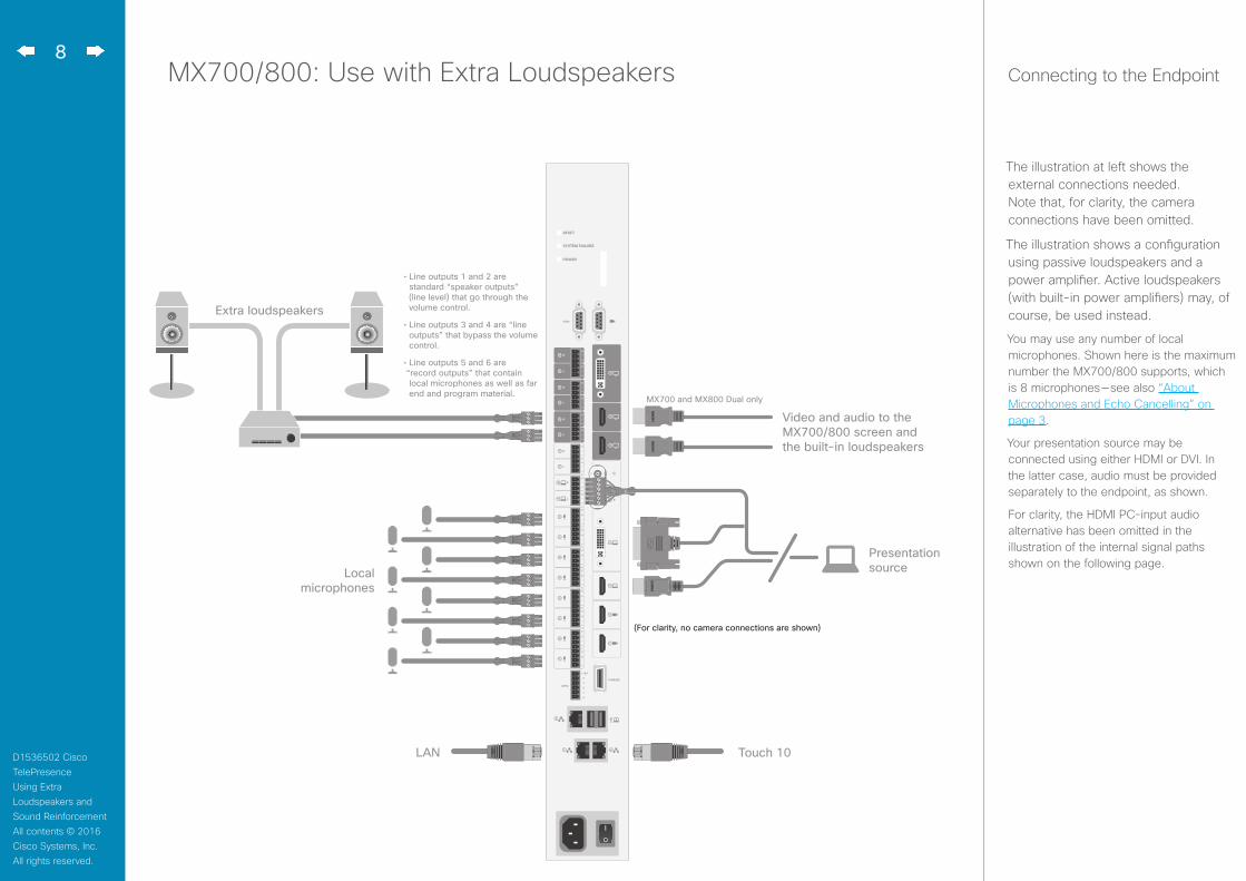
MX700/800: Use with Extra Loudspeakers Connecting to the Endpoint
The illustration at left shows the external connections needed. Note that, for clarity, the camera connections have been omitted.
The illustration shows a configuration using passive loudspeakers and a power amplifier. Active loudspeakers (with built-in power amplifiers) may, of course, be used instead.
You may use any number of local microphones. Shown here is the maximum number the MX700/800 supports, which is 8 microphones — see also “About Microphones and Echo Cancelling” on page 3.
Your presentation source may be connected using either HDMI or DVI. In the latter case, audio must be provided separately to the endpoint, as shown.
For clarity, the HDMI PC-input audio alternative has been omitted in the illustration of the internal signal paths shown on the following page.
LAN
Presentation sourceLocal
microphones
Extra loudspeakers
(For clarity, no camera connections are shown)
Touch 10
MX700 and MX800 Dual only
Video and audio to the MX700/800 screen and the built-in loudspeakers
• Line outputs 1 and 2 are standard “speaker outputs” (line level) that go through the volume control.
• Line outputs 3 and 4 are “line outputs” that bypass the volume control.
• Line outputs 5 and 6 are “record outputs” that contain local microphones as well as far end and program material.
9
D1536502 Cisco TelePresence Using Extra Loudspeakers and Sound ReinforcementAll contents © 2016 Cisco Systems, Inc. All rights reserved.
• For the initial configuration when setting this up, we recommend the use of a sound source connected to the video system as “local presentation outside a call”. Make sure you use a signal with a representative content and signal level, as well as sufficient dynamic range. Recorded speech should be a part of this signal.
• We recommend that level setting on the audio output connectors is kept at its default value (-10)
The extra loudspeakers’ level should then be set as suitable, using the loudspeakers’ own gain controls.
This will leave a range of –14 dB to +10 dB available for further adjustments, which will be needed if compensation for many people present in the room calls for a different level.
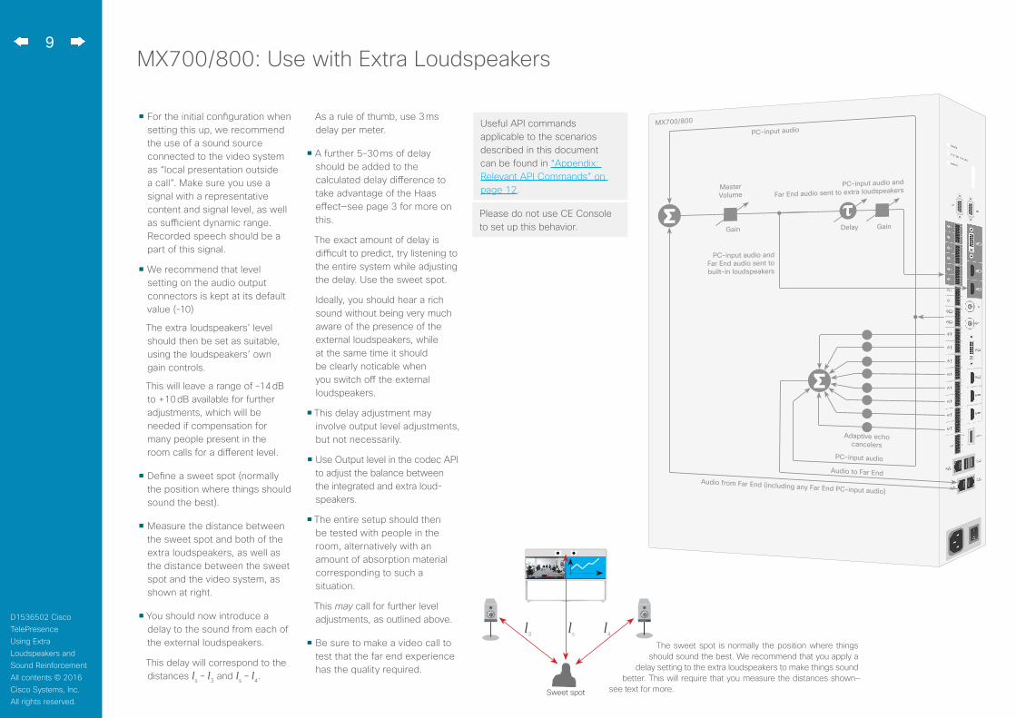
• Define a sweet spot (normally the position where things should sound the best).
• Measure the distance between the sweet spot and both of the extra loudspeakers, as well as the distance between the sweet spot and the video system, as shown at right.
• You should now introduce a delay to the sound from each of the external loudspeakers.
This delay will correspond to the distances ls – l3 and ls – l4.
As a rule of thumb, use 3 ms delay per meter.
• A further 5–30 ms of delay should be added to the calculated delay difference to take advantage of the Haas effect—see page 3 for more on this.
The exact amount of delay is difficult to predict, try listening to the entire system while adjusting the delay. Use the sweet spot.
Ideally, you should hear a rich sound without being very much aware of the presence of the external loudspeakers, while at the same time it should be clearly noticable when you switch off the external loudspeakers.
• This delay adjustment may involve output level adjustments, but not necessarily.
• Use Output level in the codec API to adjust the balance between the integrated and extra loud-speakers.
• The entire setup should then be tested with people in the room, alternatively with an amount of absorption material corresponding to such a situation.
This may call for further level adjustments, as outlined above.
• Be sure to make a video call to test that the far end experience has the quality required.
MX700/800: Use with Extra Loudspeakers
Sweet spot
l3 l4ls
Useful API commands applicable to the scenarios described in this document can be found in “Appendix: Relevant API Commands” on page 12.
Adaptive echo cancelers
PC-input audio
PC-input audio
Audio to Far EndAudio from Far End (including any Far End PC-input audio)
MX700/800
PC-input audio and
Far End audio sent to extra loudspeakers
DelayGain
Master Volume
Gain
PC-input audio and Far End audio sent to built-in loudspeakers
The sweet spot is normally the position where things should sound the best. We recommend that you apply a
delay setting to the extra loudspeakers to make things sound better. This will require that you measure the distances shown—
see text for more.
Please do not use CE Console to set up this behavior.
10
D1536502 Cisco TelePresence Using Extra Loudspeakers and Sound ReinforcementAll contents © 2016 Cisco Systems, Inc. All rights reserved.
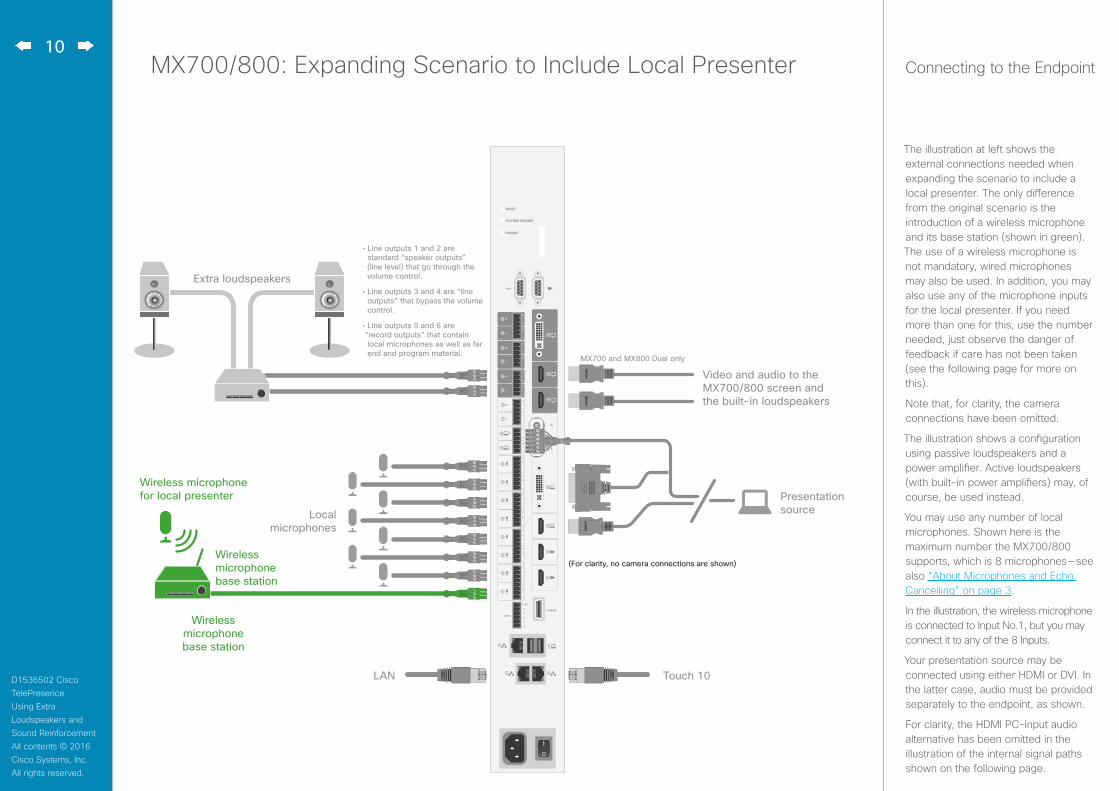
MX700/800: Expanding Scenario to Include Local Presenter Connecting to the Endpoint
LAN Touch 10
Presentation source
Wireless microphone for local presenter
Wireless microphone base station
(For clarity, no camera connections are shown)
Local microphones
Extra loudspeakers
Video and audio to the MX700/800 screen and the built-in loudspeakers
MX700 and MX800 Dual only
• Line outputs 1 and 2 are standard “speaker outputs” (line level) that go through the volume control.
• Line outputs 3 and 4 are “line outputs” that bypass the volume control.
• Line outputs 5 and 6 are “record outputs” that contain local microphones as well as far end and program material.
Wireless microphone base station
The illustration at left shows the external connections needed when expanding the scenario to include a local presenter. The only difference from the original scenario is the introduction of a wireless microphone and its base station (shown in green). The use of a wireless microphone is not mandatory, wired microphones may also be used. In addition, you may also use any of the microphone inputs for the local presenter. If you need more than one for this, use the number needed, just observe the danger of feedback if care has not been taken (see the following page for more on this).
Note that, for clarity, the camera connections have been omitted.
The illustration shows a configuration using passive loudspeakers and a power amplifier. Active loudspeakers (with built-in power amplifiers) may, of course, be used instead.
You may use any number of local microphones. Shown here is the maximum number the MX700/800 supports, which is 8 microphones — see also “About Microphones and Echo Cancelling” on page 3.
In the illustration, the wireless microphone is connected to Input No.1, but you may connect it to any of the 8 Inputs.
Your presentation source may be connected using either HDMI or DVI. In the latter case, audio must be provided separately to the endpoint, as shown.
For clarity, the HDMI PC-input audio alternative has been omitted in the illustration of the internal signal paths shown on the following page.

11
D1536502 Cisco TelePresence Using Extra Loudspeakers and Sound ReinforcementAll contents © 2016 Cisco Systems, Inc. All rights reserved.
MX700/800: Expanding Scenario to Include Local Presenter
• We assume that you have already set up your MX700/800 to work with a set of extra loudspeakers, as described on the previous page.
• Use a dedicated (and cloesly mounted) microphone for the presenter, preferably of the wearable type.
This will ensure high quality audio with low loudness variation from the presenter and low sensitivity towards other audio sources. It is important that the presenter mi-crophone does not pick up much of the audio from the built-in loudspeakers of the MX700/800 or the extra loudspeakers, when local reinforcement of the pre-senter audio is used.
This serves to avoid strong reverberation, coloration and in the worst case feedback, of the presenter audio.
Other microphones in the room, e.g. ceiling mounted microphones may still be operating, but not as a substitute for the personal microphone.
• The wearable microphone will typically be of the wireless type with a base station.
In order to avoid clipping of the codec’s microphone input, you may want to set the base station output to Mic out, rather than Line out.
If you do so, make sure the base station is not suffering damage from the phantom voltage supplied
by the codec. See also Appendix for more.
• Another strategy will be to use Line out of the base station and reduce the input sensitivity of the codec accordingly.
The codec full scale level is 22 dBu. If you have a base station supplying e.g. 18 dBu, you should not set the codec input level higher than 4.
Each step of the codec input level setting corresponds to 1dB gain. For more on this, consult the SX80 Physical Interface Guide.
• Furthermore, we do recommend that any kind of processing in the base station is avoided. We are here thinking of such things as dynamic EQ, compression, noise reduction, AGC, de-essing etc. These types of time-varying and/or non-linear processing may be detrimental to the codec’s echo cancelling performance. Fixed EQ, however, should cause no problem.
• The input signal level from the wearable microphone should be checked using the VU-meter feature of the codec. Green with occassional appearances of yellow is considered good. Note that there is no peak hold, so testing by listening will be needed. Use the gain control of the microphone base station to adjust the microphone level, if needed.
• Adjust the gain settings so that the codec input levels are the same for all microphone inputs, for a given sound level.
Should you now need to adjust the sound level, use the following guidelines:
• Use MicrophoneReinforce-ment Gain to amplify the local presenter.
• Use Master volume to amplify PC-input audio and far-end audio. This will not influence the level of the local presenter.
• You may want to fine-tune the delay at this stage.
• Finally, the entire setup should then be tested with people in the room, alternatively with an amount of absorption material corresponding to such a situation.
This may call for further level adjustments, as outlined above.
• Be sure to make a video call to test that the far end experience has the quality required.
Useful API commands applicable to the scenarios described in this document can be found in “Appendix: Relevant API Commands” on page 12.
How to navigate to the VU-meters of the codec is explained on the same page.
In the above example two microphones are used for the local reinforcement. This is just an example, feel free to use any number of the 8 microphones.
Note We do not recommend that you combine local reinforcement and SpeakerTrack.
PC-input audio and Far End audio sent to built-in loudspeakers
Microphones for local presenter
DelayGain
Gain Microphone reinforcement gain
Adaptive echo cancelers
Gain
PC-input audio
PC-input audio
Audio to Far EndAudio from Far End (including any Far End PC-input audio)
MX700/800
Local presenter, PC-input audio and
Far End audio sent to extra loudspeakersMaster Volume
Please do not use CE Console to set up this behavior.

12
D1536502 Cisco TelePresence Using Extra Loudspeakers and Sound ReinforcementAll contents © 2016 Cisco Systems, Inc. All rights reserved.
Appendix: Relevant API Commands Where are the VU-meters?
To display the VU-meters, sign in to the web interface of the codec, then navigate to Setup > Peripherals and then down to the microphone VU-meters.
Sign in to the web interface and navigate to Setup > Configuration. For more API commands, see the API guide for your system.
Audio MicrophoneReinforcement Input Microphone [1..8] ModeDescription: Set the microphone reinforcement mode individually on each microphone. The signals from all microphones with Mode = On will be mixed and fed to the selected MicrophoneReinforcement outputs. Also consult the Audio MicrophoneReinforcement Output Line Mode setting.
Valuespace: On/Off (default)
On: The microphone signal will be fed to the selected MicrophoneReinforcement outputs, as well as to the far end.
Off: The microphone signal will be sent only to the far end. It will not be fed to the selected MicrophoneReinforcement outputs.
Audio MicrophoneReinforcement Output Line [1..4] ModeDescription: Set the microphone reinforcement mode individually on each line output. If Mode = On, the line output will add the microphone reinforcement mix to its ordinary output signal. Also consult the Audio MicrophoneReinforcement Input Microphone Mode setting.
Valuespace: On/Off (default)
On: This output will deliver far-end audio, local presentation audio and the microphone reinforcement mix.
Off: This output will deliver far-end audio and local presentation audio.
Audio MicrophoneReinforcement GainDescription: The gain (in dB) that will be applied to the mixed microphone signal that is fed to the selected MicrophoneReinforcement outputs.
Valuespace: Integer (-54..15); default: -54
Use this gain to adjust the level of microphone signal that should be fed to the local output. The value -54 means “Off”, and no signal will be fed from the microphone to the output.
Audio Input Microphone [1..8] TypeDescription: Set the specified input as Line or Microphone. When set to Line the phantom voltage feeding will be turned off.
Valuespace: Line/Microphone
Audio Output Line [1..4] Delay DelayMsDescription: Set the delay to a specified value (milliseconds)
Valuespace: Integer (0..290)
Audio Output Line [1..4] LevelDescription: Output gain in decibels.
Valuespace: Integer (–24..0)
Cisco has more than 200 offices worldwide. Addresses, phone numbers, and fax numbers are listed on the Cisco Website at www.cisco.com/go/offices.
Cisco and the Cisco Logo are trademarks of Cisco Systems, Inc. and/or its affiliates in the U.S. and other countries. A listing of Cisco’s trademarks can be found at www.cisco.com/go/trademarks. Third party trademarks mentioned are the property of their respective owners. The use of the word partner does not imply a partnership relationship between Cisco and any other company. (1005R)
Americas Headquarters Cisco Systems, Inc. San Jose, CA
Asia Pacific Headquarters Cisco Systems (USA) Pte. Ltd. Singapore
Europe Headquarters Cisco Systems International BV Amsterdam, The Netherlands