using ecosystem in hwqs - lutron electronics ecosystem in hwq… · using ecosystem...
TRANSCRIPT

Using EcoSystem Ballasts/Drivers in HWQS – Rev D Page 1
Using EcoSystem® Ballasts/Drivers in HomeWorks QS
Revision D—04/2015

Using EcoSystem Ballasts/Drivers in HWQS – Rev D Page 2
1.0 OVERVIEW ...................................................................................................................................... 3
2.0 DIN-RAIL POWER MODULE (DPM) W/ ECOSYSTEM ......................................................... 4
2.1 Installation & Wiring ...................................................................................................................................... 4 2.1.1 Wiring Tips ..................................................................................................................................................... 5 2.1.2 Additional Notes ............................................................................................................................................ 5
2.2 Adding and Configuring the DPM in the Design Tab ....................................................................................... 6 2.2.1 Creating EcoSystem Loads: ............................................................................................................................ 6 2.2.2 Adding DIN-rail Power Modules and Assigning Loads to EcoSystem Links: ................................................... 7
2.3 Activating the DPMs and EcoSystem Drivers/Ballasts .................................................................................... 9 2.3.1 Activate DIN-rail Power Modules ................................................................................................................... 9 2.3.2 Activate EcoSystem Ballasts/Drivers .............................................................................................................. 9
2.4 Programming EcoSystem in the HWQS Software .......................................................................................... 14 2.4.1 Area Scene Programming Recommendations .......................................................................................... 15
3.0 GRAFIK EYE QS W/ ECOSYSTEM ............................................................................................ 17
3.1 Installation & Wiring: ................................................................................................................................... 18 3.1.1 Wiring Tips ................................................................................................................................................... 18 3.1.2 Additional Notes .......................................................................................................................................... 19
3.2 Adding and Configuring the Grafik Eye in the Design Tab ............................................................................. 19
3.3 Program and Activation Tabs ....................................................................................................................... 22
4.0 APPENDIX A – DIMMING RANGE ........................................................................................... 23
Using EcoSystem Ballasts/Drivers in HWQS – Rev D Page 3
1.0 Overview Lighting fixtures that utilize Lutron EcoSystem digitally addressable fluorescent dimming ballasts and LED drivers can be controlled in a HomeWorks QS system by using either DIN-rail Power Modules w/ EcoSystem (LQSE-2ECO-D) or GRAFIK Eye QS w/ EcoSystem main units (QSGRx-yE). DIN-rail Power Modules w/ EcoSystem are capable of controlling up to 128 EcoSystem ballasts/drivers (64 max. per EcoSystem link) and GRAFIK Eye QS w/ EcoSystem main units are capable of controlling up to 64 EcoSystem ballasts/drivers. Zones can then be grouped together into zones either in the HWQS software (for DIN-rail Power Modules) or locally at the main unit (for GRAFIK Eye QS units). The DIN-rail Power Modules support up to 64 zones per EcoSystem link and the GRAFIK Eye QS units support up to 16 zones. The EcoSystem ballasts/drivers all communicate over a 2-wire, non-polarized, topology-free, digital communication bus. The purpose of this document is to explain how to design, program, activate, and troubleshoot a HWQS system that utilizes EcoSystem ballasts/drivers. This document is split into 2 sections, with one section focused on the DIN-rail Power Module w/ EcoSystem solution, and the other section focused on the GRAFIK Eye QS w/ Ecosystem solution. Please refer to the appropriate section based on the control hardware being used on the specific project.
NOTE: Only HomeWorks QS versions 6.0.0 and later support the use of DIN-rail Power Modules w/ EcoSystem and GRAFIK Eye QS w/ EcoSystem main units. NOTE: For optimal performance, it is recommended to utilize HomeWorks QS versions 9.0.0 and later for programming EcoSystem. Refer to Section 2.4 for more information.

Using EcoSystem Ballasts/Drivers in HWQS – Rev D Page 4
2.0 DIN-rail Power Module (DPM) w/ EcoSystem
The DIN-rail Power Module w/ EcoSystem is a QS wired device that resides on the QS link and counts as 1 of the available 99 devices on the link. Each module has 2 EcoSystem links on it and each EcoSystem link can have a maximum of 64 EcoSystem ballasts/drivers that can be grouped together in up to 64 zones (128 max. per module). Below is a list of important technical documents pertaining to the DIN-rail Power Module w/ EcoSystem. Please review the information contained within these documents as they will be referred to throughout this document: DIN-rail Power Module w/ EcoSystem Specification Submittal DIN-rail Power Module w/ EcoSystem Installation Guide DIN-rail Power Module Enclosure
2.1 Installation & Wiring Refer to the DIN-rail Power Module w/ EcoSystem Specification Submittal and Installation Guide (above) for information regarding the installation and wiring of modules. See below for a one-line system example wiring diagram:

Using EcoSystem Ballasts/Drivers in HWQS – Rev D Page 5
2.1.1 Wiring Tips
In addition to what is already called out in the EcoSystem Specification Submittal and Installation Guide documents, below are some EcoSystem wiring tips: 1. DO NOT connect line voltage to the 2-wire EcoSystem link 2. DO NOT connect the 2-wire EcoSystem link to earth ground (doing this will typically result in
fixtures flickering or being stuck at low end) 3. EcoSystem wiring can be run in the same conduit as line voltage because it is treated as
Class 1 wiring. Please follow all Class 1 safety rules for EcoSystem wiring. 4. EcoSystem wiring is topology-free (daisy-chain, star, homerun, t-tap), however, for ease of
troubleshooting Lutron recommends using a daisy-chain wiring topology 5. If using a daisy-chain wiring topology, it is recommended to run a “loop back” wire for the
EcoSystem link from the last ballast/driver on the link back to the DPM but not physically connected to the unit. This “loop back” wire would only be connected to the DPM in the event of a wiring issue somewhere in the middle of the EcoSystem link.
2.1.2 Additional Notes
1. Each DPM is 9 DIN modules wide and can be mounted in a 3rd party DIN-rail panel or in a
Lutron DIN-rail Power Module Enlcosure 2. Each DPM counts as 1 device on the QS Link (PDU count = 0) 3. Each DPM has 2 EcoSystem links and each EcoSystem link can control a maximum of 64
EcoSystem ballasts/drivers a. NOTE: It is recommended not to exceed 63 ballasts/drivers on any given link in order
to take advantage of the single ballast auto-replacement feature, which will automatically re-address a single ballast that is replaced on the link with the address of the previous ballast that failed or had been replaced on the same link. This feature will work on any EcoSystem link with 63 or less ballasts on the link. If more than 1 ballast/driver needs to be replaced on the link you will need to activate the new ballasts/drivers into the system in the software (see “HWQS Software – Activate Tab” section of this document for more details on ballast/driver activation)
4. EcoSystem ballasts/drivers can be grouped together into lighting zones in the HWQS
software (see “HWQS Software – Design Tab” section). A zone is a group of independently addressed ballasts which will operate and be controlled as a single unit, the same as a traditional incandescent switch leg with multiple blubs or fixtures on it.
5. Upon completion of EcoSystem ballast/driver wiring, it is recommended to verify your wiring
by using the “Test” button on the DPM. Refer to the DIN-rail Power Module w/ EcoSystem Installation Guide for information on how to verify wiring using the “Test” button.

Using EcoSystem Ballasts/Drivers in HWQS – Rev D Page 6
6. Use Area Scene programming - when multiple zones of EcoSystem controlled lighting is part of the same scene, it is recommended to utilize the 9.0 and newer versions of HomeWorks QS programming software and to assign EcoSystem zones to the scene by using the Area Scene feature for the areas which contain the EcoSystem loads. In the Assignable Items dropdown menu, these show up as “Lighting – Areas” instead of the more commonly used “Lighting – Zones “. Refer to Section 2.4 for more information.
2.2 Adding and Configuring the DPM in the Design Tab
2.2.1 Creating EcoSystem Loads:
1. Navigate to the Design > Loads screen and verify that at a minimum the following columns
are visible. If they are not, click on Customize Columns and add them in. a. Zone # b. Zone Name c. Load # d. Fixture (required if using a Fixture Schedule) e. Load Type (required if not using a Fixture Schedule) f. Fixture Wattage g. Fixture Qty h. Emergency
2. Add in the appropriate number of EcoSystem ballasts/drivers in a selected area by following the steps below:
a. Enter a Zone Number and Zone Name in the “Zone #” and “Zone Name” fields (i.e. Zone # = 1 and Zone Name = Downlights). To zone multiple ballasts/drivers together, modify the zone number of the selected ballast/driver to match the ballasts/drivers you wish to zone it with.
b. In the “Load #” field, enter the load number of each EcoSystem ballast/driver in the following format [DPM (Panel #)-(DPM # in panel)-(EcoSystem Link #)-(EcoSystem Address #)]. For example, if the ballast/driver is connected to a DPM in Panel #1, DPM #1 in that panel, EcoSystem Link #1, and you want it to be Address #1, the Load # would be DPM 1-1-1-1. Using this naming convention for the Load # will ease in the assignment, addressing and troubleshooting process (covered later in this document).
i. NOTE 1: For the EcoSystem address number, you will start with #1 and increment by 1 for each additional ballast/driver wired on the same EcoSystem link. Remember not to exceed 63 ballasts/drivers on a link in order for the single ballast auto-replacement feature to work.
ii. NOTE 2: You will want to note on your reflected ceiling plans the Load # of each EcoSystem fixture in the project to aid in the ballast/driver addressing/activation process (covered later in this document). Failure to do this will make ballast/driver addressing and troubleshooting very difficult.
c. If you created a Fixture Schedule in your project, assign the appropriate EcoSystem fixture to the load in the “Fixture” field, otherwise set the “Load Type” column to an EcoSystem load type.

Using EcoSystem Ballasts/Drivers in HWQS – Rev D Page 7
d. Enter the appropriate fixture wattage in the “Fixture Wattage” field and set the “Fixture Qty” field to 1 since each EcoSystem ballast/driver needs its own unique address.
e. In the “Emergency” field, enter the emergency level for the fixture. The emergency level will trigger when the ballast/driver is still receiving line voltage power, but the EcoSystem link is disconnected or de-energized. EcoSystem ballasts/drivers will go to their emergency level when one of the EcoSystem link wires is removed or the DPM is powered down, thus de-energizing the EcoSystem links.
3. Repeat step 2 for each additional EcoSystem ballast/driver. See Figure 1 below for an
example of an area that contains 11 EcoSystem ballasts/drivers and 3 lighting zones (Downlights, Sconces, Pendant).
Figure 1
2.2.2 Adding DIN-rail Power Modules and Assigning Loads to EcoSystem Links:
1. Navigate to the Design > Equipment screen and add a “DIN-rail Power Module Eco” to
your Toolbox. If you will be mounting the modules in Lutron DIN-rail panels, add the panel(s) to your Toolbox as well.
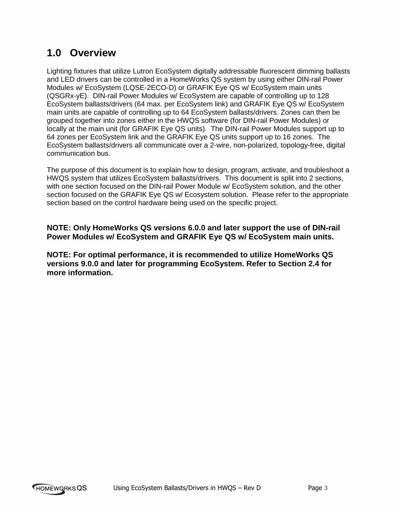
2. Add the appropriate number of DPM’s into your project and name them using the following format, [DPM (Panel #)-(DPM #)]. For example, if you are mounting 2 DPM’s in Lutron DIN-rail panels that house 2 DPM’s each (HQ-DP2), you would name the first module DPM 1-1, and the second module DPM 1-2. See Figure 2 below.
Using EcoSystem Ballasts/Drivers in HWQS – Rev D Page 8
Figure 2
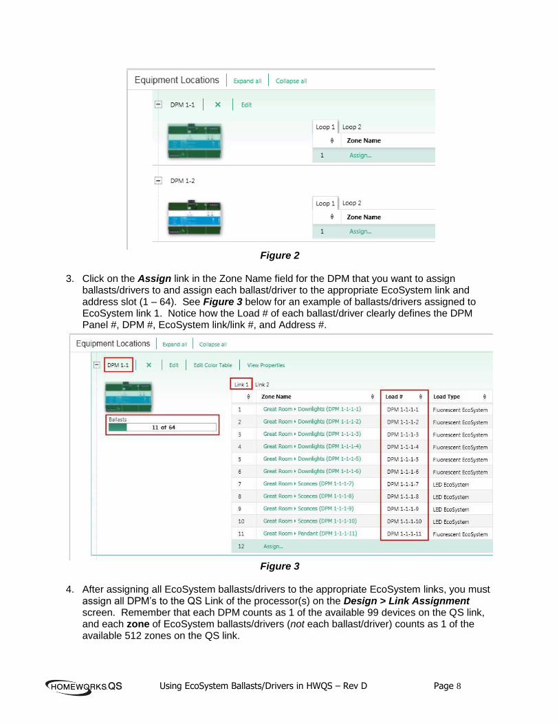
3. Click on the Assign link in the Zone Name field for the DPM that you want to assign
ballasts/drivers to and assign each ballast/driver to the appropriate EcoSystem link and address slot (1 – 64). See Figure 3 below for an example of ballasts/drivers assigned to EcoSystem link 1. Notice how the Load # of each ballast/driver clearly defines the DPM Panel #, DPM #, EcoSystem link/link #, and Address #.
Figure 3
4. After assigning all EcoSystem ballasts/drivers to the appropriate EcoSystem links, you must
assign all DPM’s to the QS Link of the processor(s) on the Design > Link Assignment screen. Remember that each DPM counts as 1 of the available 99 devices on the QS link, and each zone of EcoSystem ballasts/drivers (not each ballast/driver) counts as 1 of the available 512 zones on the QS link.

Using EcoSystem Ballasts/Drivers in HWQS – Rev D Page 9
2.3 Activating the DPMs and EcoSystem Drivers/Ballasts
2.3.1 Activate DIN-rail Power Modules
1. Navigate to the Activate > Devices screen and select the QS link(s) of the processor that
the DPM(s) are assigned to.
Figure 4
2. Activate the DPM(s) on the QS link(s) by pressing and holding a button on each DPM, or
manually entering in each DPM’s serial number, or barcode scanning in each DPM’s serial number. The DPM(s) must be activated before activating/addressing any EcoSystem ballasts/drivers.
Figure 5
2.3.2 Activate EcoSystem Ballasts/Drivers
1. Navigate to the Activate > Ballasts screen and select the EcoSystem link of ballasts/drivers
to be activated from the “Selected device loop” drop-down menu. See Figure 6 below.
Figure 6

Using EcoSystem Ballasts/Drivers in HWQS – Rev D Page 10
2. After selecting the EcoSystem link to be activated, you can verify the wiring of all
ballasts/drivers on the link by setting all fixtures to High End, Low End, and Off via the buttons in the software. See Figure 7 below. If you notice any ballasts which fail to respond as expected, please correct the issue before proceeding to addressing. Note that you can also test the EcoSystem link wiring at the DPM itself by using the “Test” button on the unit (see “Installation & Wiring” section).
Figure 7
3. After verifying the link wiring, the next step is to activate all new ballasts/drivers on the link.
If you are activating a link of ballasts for the first time you will want to choose the second option in the list to “Activate all ballasts”. If you have already addressed some ballasts on the link and are replacing or adding ballasts, you will want to choose the first option in the list to “Activate only new/unaddressed ballasts” so that the ballasts that are already addressed do not get unaddressed.
After choosing the appropriate option, click on “Start Activation”.
Figure 8
4. Verify that the number of ballasts/drivers detected on the link matches the number of
ballasts/drivers assigned to that link in the database. See Figure 9 below.
Figure 9

Using EcoSystem Ballasts/Drivers in HWQS – Rev D Page 11
5. Click on “Customize Columns” above the list of ballasts in the grid and check the box to
show “Address On Link”. See Figure 10 below. Notice how the last number of the load number in parentheses of each ballast/driver correlates to the matching “Address On Link” number. This will help to aid in the addressing and troubleshooting process.
Figure 10
6. At this point, 1 random fixture on the link will begin to flash in order to identify itself. If you
have multiple areas on the same EcoSystem link (which is likely), it is easiest to address ballasts on an area by area basis rather than walking throughout the residence trying to find the fixture that is flashing. To aid in this process, click on the “Flash Next Ballast” link until a fixture in the area that you are trying to activate ballasts in beings to flash. For example, if you are trying to activate ballasts/drivers in the Great Room, click on “Flash Next Ballast” until a fixture begins to flash in the Great Room. Using your reflected ceiling plan with the load numbers of each EcoSystem fixture noted on it, identify the fixture that is flashing and click on “Activate” in the Action column for that fixture (i.e. DPM 1-1-1-2 in the Great Room). See Figure 11 below.
Figure 11
NOTE: If you accidentally skipped a fixture that was flashing before activating it, you can click on the “Flash Previous Ballast” link to go back to that fixture.

Using EcoSystem Ballasts/Drivers in HWQS – Rev D Page 12
7. After successfully activating a ballast/driver, the Status column will display “Good ” and the
Action column will display the word “Deactivate”. See Figure 12 below.
Figure 12
8. Repeat step 6 until all ballasts/drivers on the link have been successfully
addressed/activated. 9. Upon completion of addressing/activating all ballasts/drivers on a link, click on Exit
Activation to go back to the main ballast activation screen. 10. The final step in the ballast/driver activation process is to verify that all ballast/drivers were
activated in the correct areas using the correct addresses. To begin this process, click on the “Verify” button. See Figure 13 below.
Figure 13

Using EcoSystem Ballasts/Drivers in HWQS – Rev D Page 13
11. Click on Start to begin the verification process. Once the verification process begins, the
ballasts/drivers will flash one at a time in the order that they are listed on the screen. The ballast/driver that is flashing will be highlighted in the grid. You can reorder the grid by clicking in the column headers. You can also pause and resume the verification process at any time. See Figure 14 below.
Figure 14
12. Once all ballasts/drivers have been verified click on the Exit button to exit the verification
process. 13. Repeat steps 1 – 12 for all other EcoSystem links in the project.

Using EcoSystem Ballasts/Drivers in HWQS – Rev D Page 14
2.4 Programming EcoSystem in the HWQS Software 1. EcoSystem zones can be programmed to any system triggers (keypad buttons, contact
closures, timeclocks, etc.) or 3rd party control similar to any other lighting zone.
NOTE: The HWQS software allows for a maximum fade time of 4 hours (14,400 seconds), however, EcoSystem ballasts/drivers support a maximum fade time of 1 hour (3,600 seconds). Any additional fade time programmed beyond 1 hour for EcoSystem load types will be ignored and the load(s) will fade over the course of 1 hour.
2. For optimal performance utilize 9.0 and newer programming software and Area Scenes. Area Scenes are similar to Shared Scenes but the biggest difference is that an Area Scene only applies to a single area of the Area Tree (Shared Scenes can span multiple areas). Create the Area Scenes by going to Program > Area Scenes in the Program tab drop down menu as shown below.
Each area has a pre-defined set of Area Scenes already created which essentially send all lighting zones in the area to common defined preset levels (100%, 75%, 50%, 25%, and 0%). These default Presets can be renamed and re-programmed or new Area Scene presets can be created and added in addition to the default Presets. In the case of EcoSystem, Presets would typically be created as new and programmed to only control the EcoSystem lights within the space. Zones that are not to be affected by a particular area scene can be set to unaffected. When naming the Preset, it is recommended to name the Preset after the scene that it will be assigned to (ex. Goodnight or Welcome). Each area within the database can have 16 area scenes plus an off scene.

Using EcoSystem Ballasts/Drivers in HWQS – Rev D Page 15
Once the Area Scenes have been defined they can be assigned to the trigger by selecting the “Lighting – Areas” option under the Assignable Items drop down menu.
2.4.1 Area Scene Programming Recommendations
Do not utilize different delays for zones within an area –If the staggered or delayed on is desired, using standard Lighting Zone programming is recommended to reduce Transfer times
Using EcoSystem Ballasts/Drivers in HWQS – Rev D Page 16
1. No warnings or pop-up messages in the software will appear to alert the programmer of the above as the software will assume that the different programmed delay times are intentional
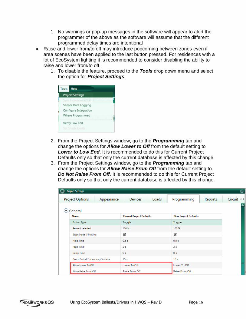
Raise and lower from/to off may introduce popcorning between zones even if area scenes have been applied to the last button pressed. For residences with a lot of EcoSystem lighting it is recommended to consider disabling the ability to raise and lower from/to off.
1. To disable the feature, proceed to the Tools drop down menu and select the option for Project Settings.
2. From the Project Settings window, go to the Programming tab and change the options for Allow Lower to Off from the default setting to Lower to Low End. It is recommended to do this for Current Project Defaults only so that only the current database is affected by this change.
3. From the Project Settings window, go to the Programming tab and change the options for Allow Raise From Off from the default setting to Do Not Raise From Off. It is recommended to do this for Current Project Defaults only so that only the current database is affected by this change.

Using EcoSystem Ballasts/Drivers in HWQS – Rev D Page 17
3.0 GRAFIK Eye QS w/ EcoSystem
GRAFIK Eye QS w/ EcoSystem units are available in a 6, 8, or 16 zone variety. Zones 1, 2, and 3 on any GRAFIK Eye QS w/ EcoSystem unit are integral line voltage dimming zones, but can be configured to control EcoSystem lighting zones as well. GRAFIK Eye QS w/ EcoSystem main units can be used as either QS wired devices in the system or as RF devices in the system. Each GRAFIK Eye QS w/ Ecosystem unit can have a maximum of 64 EcoSystem ballasts/drivers connected to it using the 2-wire EcoSystem digital communication bus. EcoSystem ballasts/drivers can then be grouped together into zones locally at the GRAFIK Eye QS main unit. Below is a list of important technical documents pertaining to the GRAFIK Eye QS w/ EcoSystem main unit. Please review the information contained within these documents as they will be referred to throughout this document: GRAFIK Eye QS w/ EcoSystem Specification Submittal GRAFIK Eye QS with EcoSystem Installation and Operation Guide

Using EcoSystem Ballasts/Drivers in HWQS – Rev D Page 18
3.1 Installation & Wiring: Refer to the GRAFIK Eye QS w/ EcoSystem Specification Submittal and Installation and Operation Guide (above) for information regarding the wiring and local addressing/zone configuration of EcoSystem ballasts/drivers connected to GRAFIK Eye QS w/ EcoSystem units. See below for a one-line EcoSystem wiring example:
3.1.1 Wiring Tips
In addition to what is already called out in the EcoSystem Specification Submittal and Installation Guide documents, below are some EcoSystem wiring tips; 1. DO NOT connect line voltage to the 2-wire EcoSystem link 2. DO NOT connect the 2-wire EcoSystem link to earth ground (doing this will typically result in
fixtures flickering or being stuck at low end) 3. EcoSystem wiring can be run in the same conduit as line voltage because it is treated as
Class 1 wiring. Please follow all Class 1 safety rules for EcoSystem wiring. 4. EcoSystem wiring is topology-free (daisy-chain, star, homerun, t-tap), however, for ease of
troubleshooting Lutron recommends using a daisy-chain wiring topology 5. If using a daisy-chain wiring topology, it is recommended to run a “loop back” wire for the
EcoSystem link from the last ballast/driver on the link back to the GRAFIK Eye QS unit but not physically connected to the unit. This “loop back” wire would only be connected to the main control unit in the event of a wiring issue somewhere in the middle of the EcoSystem link.

Using EcoSystem Ballasts/Drivers in HWQS – Rev D Page 19
3.1.2 Additional Notes
1. Each GRAFIK Eye QS w/ EcoSystem unit counts as 1 device on the QS or RF Link (PDU
count = 0) 2. Each GRAFIK Eye QS w/ EcoSystem unit has 1 EcoSystem link that can control a maximum
of 64 EcoSystem ballasts/drivers 3. EcoSystem ballasts/drivers are grouped together into lighting zones at the GRAFIK Eye QS
unit itself (refer to the “EcoSystem Setup” section in the GRAFIK Eye QS with EcoSystem Installation and Operation Guide for more details)
3.2 Adding and Configuring the Grafik Eye in the Design Tab
1. Navigate to the “Design > Controls” screen and add either a QS wired or RF GRAFIK
Eye QS w/ EcoSystem unit to the Toolbox. See Figure 1 below.
Figure 1

Using EcoSystem Ballasts/Drivers in HWQS – Rev D Page 20
2. Navigate to the “Design > Loads” screen and add the appropriate number of EcoSystem
Fluorescent and/or LED loads in each area. Each GRAFIK Eye QS with EcoSystem unit
can have a maximum of 64 EcoSystem ballasts/drivers connected to it and can control a
maximum of up to 16 zones, however, you are unable to change the “Fixture Qty” to
anything other than 1 for an EcoSystem load type in the software. For EcoSystem
zones that contain multiple ballasts/drivers you will need to leave the fixture quantity set
to 1 and enter the TOTAL fixture wattage in the “Fixture Wattage” field.
For example, if you have 4 EcoSystem Sconce fixtures that are 25 W each and are all in
the same zone, you would enter in a “Fixture Wattage” of 100 W and leave the “Fixture
Qty” set to 1. See Figure 2 below.
Figure 2
NOTE: Even though the software will make it look like only 6, 8, or 16 ballasts are
connected to the GRAFIK Eye QS w/ EcoSystem main unit, you need to remember if
you have multiple ballasts grouped into zones that you cannot physically exceed 64
ballasts per main unit.

Using EcoSystem Ballasts/Drivers in HWQS – Rev D Page 21
3. Add the appropriate number of GRAFIK Eye QS w/ EcoSystem units to each area on the
“Design > Controls” screen and assign each EcoSystem zone to its corresponding unit.
The first 3 zones can be used as line voltage dimming zones or they can be used to
control EcoSystem ballasts/drivers, as shown below in Figure 3.
Figure 3
Using EcoSystem Ballasts/Drivers in HWQS – Rev D Page 22
3.3 Program and Activation Tabs
1. The EcoSystem ballasts/drivers can be programmed to any system triggers (keypad
buttons, contact closures, timeclocks, etc.) or 3rd party control, just like other load types.
Note that the programming suggestions for the Din Rail Module in Section 2.4 do not
pertain to the Grafik Eye QS. The changes for EcoSystem programming in the 9.0
software do not apply to the Grafik Eye QS controlled EcoSystem zones.
2. Device activation of GRAFIK Eye QS units can occur either before or after the
EcoSystem ballasts/drivers have been addressed and grouped together into zones
locally at the main unit.
NOTE: All ballast/driver addressing and zoning is done locally at the main unit, not in the
HWQS software. Refer to the “GRAFIK Eye QS with EcoSystem Installation and
Operation Guide” for more information on the wiring and local addressing/zone
configuration of the EcoSystem ballasts/drivers connected to each unit.
Contact Lutron:
Lutron Electronics Co, Inc. 7200 Suter Road Coopersburg, PA 18036-1299 U.S.A. Technical Support: 1-800-523-9466 Email: [email protected]

Using EcoSystem Ballasts/Drivers in HWQS – Rev D Page 23
4.0 Appendix A – Dimming Range EcoSystem LED drivers support both a 1% and a more cost effective 5% low end. Understanding low end is critical to apply LED lighting to areas of a residence. The 1% and 5% low end values are stating that a fixture with one of those two driver options will output 1% or 5% of its light intensity otherwise defined as the luminance on a one-square foot surface of which there is a uniformly distributed flux of one lumen. These percentages are measured using a light meter. The most important aspect of understanding the dimming range is the correlation of the measured low end to the perceived low end as observed by the human eye. The human eye is much more dynamic than a light meter in that it can adjust to varying conditions within the environment. Dim the lights to a low level and the human eye will compensate by dilating the pupil to allow more light in. The opposite is true at the brighter end of the range. While 20% to 100% sounds like a large, potentially satisfactory, dimming range an understanding of perceived versus measured light will typically indicate that a 20% low end will be inadequate in most lighting applications.
Measured Low End Perceived Low End
1% 10%
5% 22%
10% 32%
20% 45%
Home theaters, bedrooms, and dining rooms ideally require the ability to achieve 1% or less low end dimming. Areas such as the foyer, hallways, and stairwells may be fine utilizing 5% low end. For most residential applications, there is a larger chance that measured light above 5% at low end will be undesirable as a result of how bright the human perceives the space to be. The below chart is a visual representation of the relationship between perceived and measured light levels across the entire dimming range.

Using EcoSystem Ballasts/Drivers in HWQS – Rev D Page 24
Using EcoSystem Ballasts/Drivers in HWQS – Rev D Page 25
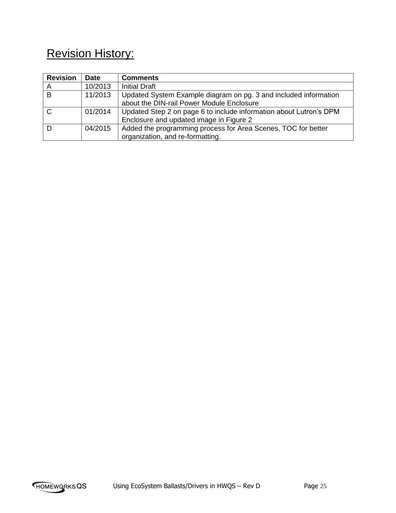
Revision History: Revision Date Comments
A 10/2013 Initial Draft
B 11/2013 Updated System Example diagram on pg. 3 and included information about the DIN-rail Power Module Enclosure
C 01/2014 Updated Step 2 on page 6 to include information about Lutron’s DPM Enclosure and updated image in Figure 2
D 04/2015 Added the programming process for Area Scenes, TOC for better organization, and re-formatting.