using bundles to create logical configurations - juniper networks
TRANSCRIPT

CTP Series Circuit to Packet Platform
UsingBundles toCreate Logical Configurations forPhysical Interfaces
Release
6.6
Published: 2014-03-05
Copyright © 2014, Juniper Networks, Inc.

Juniper Networks, Inc.1194 North Mathilda AvenueSunnyvale, California 94089USA408-745-2000www.juniper.net
Copyright © 2014, Juniper Networks, Inc. All rights reserved.
Juniper Networks, Junos, Steel-Belted Radius, NetScreen, and ScreenOS are registered trademarks of Juniper Networks, Inc. in the UnitedStates and other countries. The Juniper Networks Logo, the Junos logo, and JunosE are trademarks of Juniper Networks, Inc. All othertrademarks, service marks, registered trademarks, or registered service marks are the property of their respective owners.
Juniper Networks assumes no responsibility for any inaccuracies in this document. Juniper Networks reserves the right to change, modify,transfer, or otherwise revise this publication without notice.
Using Bundles to Create Logical Configurations for Physical Interfaces, CTP Release 6.6, CTPView Release 4.6Copyright © 2014, Juniper Networks, Inc.All rights reserved.
Revision HistorySeptember 2013—CTP Software Configuration Guide, CTP Release 6.6, CTPView Release 4.6
The information in this document is current as of the date on the title page.
ENDUSER LICENSE AGREEMENT
The Juniper Networks product that is the subject of this technical documentation consists of (or is intended for use with) Juniper Networkssoftware. Use of such software is subject to the terms and conditions of the End User License Agreement (“EULA”) posted athttp://www.juniper.net/support/eula.html. By downloading, installing or using such software, you agree to the terms and conditions ofthat EULA.
Copyright © 2014, Juniper Networks, Inc.ii

Table of Contents
Part 1 Overview
Chapter 1 Overview of CTP Bundles . . . . . . . . . . . . . . . . . . . . . . . . . . . . . . . . . . . . . . . . . . . 3
Types of Bundles Overview . . . . . . . . . . . . . . . . . . . . . . . . . . . . . . . . . . . . . . . . . . . . 3
Interface Naming Conventions for the CTP Series . . . . . . . . . . . . . . . . . . . . . . . . . . 4
Serial Multiservice Interface Module Overview . . . . . . . . . . . . . . . . . . . . . . . . . . . . . 5
Audio Mode . . . . . . . . . . . . . . . . . . . . . . . . . . . . . . . . . . . . . . . . . . . . . . . . . . . . . 5
4WTO Mode . . . . . . . . . . . . . . . . . . . . . . . . . . . . . . . . . . . . . . . . . . . . . . . . . . . . 6
IRIG Mode . . . . . . . . . . . . . . . . . . . . . . . . . . . . . . . . . . . . . . . . . . . . . . . . . . . . . . 6
TDC Mode . . . . . . . . . . . . . . . . . . . . . . . . . . . . . . . . . . . . . . . . . . . . . . . . . . . . . . 7
Adaptive Clocking Overview for CTP Bundles . . . . . . . . . . . . . . . . . . . . . . . . . . . . . . 7
Determining Optimal Packet Size for CTP Bundles Overview . . . . . . . . . . . . . . . . . 8
Bandwidth for Transporting Serial Data . . . . . . . . . . . . . . . . . . . . . . . . . . . . . . 8
Packet Creation Delay . . . . . . . . . . . . . . . . . . . . . . . . . . . . . . . . . . . . . . . . . . . . . 9
Performance of the IP Network . . . . . . . . . . . . . . . . . . . . . . . . . . . . . . . . . . . . . 9
Providing QoS for CTP Bundles by Using Service Type Overview . . . . . . . . . . . . . . 10
Circuit Startup Process Overview . . . . . . . . . . . . . . . . . . . . . . . . . . . . . . . . . . . . . . . 11
Transparent Encoding Overview . . . . . . . . . . . . . . . . . . . . . . . . . . . . . . . . . . . . . . . . 12
Transparent Encoding Applications and Support Overview . . . . . . . . . . . . . . 12
How Basic Transparent Encoding Works . . . . . . . . . . . . . . . . . . . . . . . . . . . . . 12
Using Phase-Correction FIFO Buffer with Transparent Encoding . . . . . . . . . . 13
UsingSendTiming (ST)Clocking forHigherSpeedCircuitswithTransparent
Encoding . . . . . . . . . . . . . . . . . . . . . . . . . . . . . . . . . . . . . . . . . . . . . . . . . . . 15
TDM/TDC Encoding Overview . . . . . . . . . . . . . . . . . . . . . . . . . . . . . . . . . . . . . . . . . 17
How TDM Interleaving Works . . . . . . . . . . . . . . . . . . . . . . . . . . . . . . . . . . . . . . 17
How the CTP Implementation of TDM/TDCWorks . . . . . . . . . . . . . . . . . . . . . 18
TDM Rates . . . . . . . . . . . . . . . . . . . . . . . . . . . . . . . . . . . . . . . . . . . . . . . . . . . . . 18
TDM High-Speed and Low-Speed Ports . . . . . . . . . . . . . . . . . . . . . . . . . . . . . 19
Chapter 2 Configuring CTP Bundles . . . . . . . . . . . . . . . . . . . . . . . . . . . . . . . . . . . . . . . . . . . 21
Adding a Bundle (CTPView) . . . . . . . . . . . . . . . . . . . . . . . . . . . . . . . . . . . . . . . . . . 22
Adding a Bundle (CTP Menu) . . . . . . . . . . . . . . . . . . . . . . . . . . . . . . . . . . . . . . . . . 23
Configuring IP Parameters for CTP Bundles (CTPView) . . . . . . . . . . . . . . . . . . . . 23
Configuring IP Parameters for CTP Bundles (CTP Menu) . . . . . . . . . . . . . . . . . . . 25
Configuring Circuit Startup Parameters for CTP Bundles (CTPView) . . . . . . . . . . 27
Configuring Circuit Startup Parameters for CTP Bundles (CTP Menu) . . . . . . . . . 28
Configuring the CTP Bundle Data Packet Protocol and OAM Port (CTP
Menu) . . . . . . . . . . . . . . . . . . . . . . . . . . . . . . . . . . . . . . . . . . . . . . . . . . . . . . . . 29
Ethernet Media Configuration Overview . . . . . . . . . . . . . . . . . . . . . . . . . . . . . . . . . 29
Displaying Ethernet Media Information (CTP Menu) . . . . . . . . . . . . . . . . . . . . . . . 30
Configuring Ethernet Media (CTP Menu) . . . . . . . . . . . . . . . . . . . . . . . . . . . . . . . . 30
iiiCopyright © 2014, Juniper Networks, Inc.

Configuring the Direction of the Circuit (CTPView) . . . . . . . . . . . . . . . . . . . . . . . . 32
Configuring the Direction of the Circuit (CTP Menu) . . . . . . . . . . . . . . . . . . . . . . . 32
Configuring Virtual IP Parameters for CTP Bundles (CTPView) . . . . . . . . . . . . . . . 33
Configuring Virtual IP Parameters for CTP Bundles (CTP Menu) . . . . . . . . . . . . . 34
Configuring the Missing Packet Fill Pattern for CTP Bundles (CTPView) . . . . . . . 35
Configuring the Missing Packet Fill Pattern for CTP Bundles (CTP Menu) . . . . . . 36
Configuring IP Forwarding for CTP Bundles (CTPView) . . . . . . . . . . . . . . . . . . . . . 36
Configuring IP Forwarding for CTP Bundles (CTP Menu) . . . . . . . . . . . . . . . . . . . . 37
Configuring Signaling for CTP Bundles (CTPView) . . . . . . . . . . . . . . . . . . . . . . . . 39
Configuring Signaling for CTP Bundles (CTP Menu) . . . . . . . . . . . . . . . . . . . . . . . 43
Configuring Serial Port Parameters for CTP Bundles (CTPView) . . . . . . . . . . . . . 47
Configuring Serial Port Parameters for CTP Bundles (CTP Menu) . . . . . . . . . . . . 49
Configuring Transparent Encoding for CTP Bundles (CTP Menu) . . . . . . . . . . . . . 53
Configuring Bundle Pairs for TDM/TDC Operation (CTPView) . . . . . . . . . . . . . . . 54
Configuring the High-Speed CTP Bundle for TDM/TDC Operation
(CTPView) . . . . . . . . . . . . . . . . . . . . . . . . . . . . . . . . . . . . . . . . . . . . . . . . . 55
Configuring the Low-Speed CTP Bundle for TDM/TDC Operation
(CTPView) . . . . . . . . . . . . . . . . . . . . . . . . . . . . . . . . . . . . . . . . . . . . . . . . . 56
Configuring Bundle Pairs for TDM/TDC Operation (CTP Menu) . . . . . . . . . . . . . . 56
Configuring the High-Speed CTP Bundle for TDM/TDC Operation (CTP
Menu) . . . . . . . . . . . . . . . . . . . . . . . . . . . . . . . . . . . . . . . . . . . . . . . . . . . . . 57
Configuring the Low-Speed CTP Bundle for TDM/TDC Operation (CTP
Menu) . . . . . . . . . . . . . . . . . . . . . . . . . . . . . . . . . . . . . . . . . . . . . . . . . . . . . 58
Configuring T1 and E1 Port Parameters for CTP Bundles (CTPView) . . . . . . . . . . 59
Configuring T1 and E1 Port Parameters for CTP Bundles (CTP Menu) . . . . . . . . . . 61
Configuring Multiservice Port Parameters for CTP Bundles (CTPView) . . . . . . . . 64
Configuring Multiservice Audio Mode Port Parameters for CTP Bundles
(CTPView) . . . . . . . . . . . . . . . . . . . . . . . . . . . . . . . . . . . . . . . . . . . . . . . . . 64
Configuring Multiservice IRIG-B Mode Port Parameters for CTP Bundles
(CTPView) . . . . . . . . . . . . . . . . . . . . . . . . . . . . . . . . . . . . . . . . . . . . . . . . . 65
Configuring Multiservice TDCMode Parameters for CTP Bundles
(CTPView) . . . . . . . . . . . . . . . . . . . . . . . . . . . . . . . . . . . . . . . . . . . . . . . . . 67
Configuring Multiservice 4WTOMode Port Parameters for CTP Bundles
(CTPView) . . . . . . . . . . . . . . . . . . . . . . . . . . . . . . . . . . . . . . . . . . . . . . . . . 68
Configuring Multiservice Port Parameters for CTP Bundles (CTP Menu) . . . . . . . 69
ConfiguringMultiserviceAudioModePortParameters forCTPBundles (CTP
Menu) . . . . . . . . . . . . . . . . . . . . . . . . . . . . . . . . . . . . . . . . . . . . . . . . . . . . . 70
Configuring Multiservice IRIG-B Mode Port Parameters for CTP Bundles
(CTP Menu) . . . . . . . . . . . . . . . . . . . . . . . . . . . . . . . . . . . . . . . . . . . . . . . . 72
Configuring Multiservice TDCMode Parameters for CTP Bundles (CTP
Menu) . . . . . . . . . . . . . . . . . . . . . . . . . . . . . . . . . . . . . . . . . . . . . . . . . . . . . 73
Configuring Multiservice 4WTOMode Port Parameters for CTP Bundles
(CTP Menu) . . . . . . . . . . . . . . . . . . . . . . . . . . . . . . . . . . . . . . . . . . . . . . . . 74
Configuring 4WTO Port Parameters for CTP Bundles (CTPView) . . . . . . . . . . . . . 76
Configuring 4WTO Port Parameters for CTP Bundles (CTP Menu) . . . . . . . . . . . . 79
Configuring IRIG-B Port Parameters for CTP Bundles (CTPView) . . . . . . . . . . . . . 81
Configuring IRIG-B Port Parameters for CTP Bundles (CTP Menu) . . . . . . . . . . . . 83
Configuring Advanced Port Options for CTP Bundles (CTPView) . . . . . . . . . . . . . 85
Configuring Advanced Port Options for CTP Bundles (CTP Menu) . . . . . . . . . . . . 86
Copyright © 2014, Juniper Networks, Inc.iv
Using Bundles to Create Logical Configurations for Physical Interfaces, CTP Release 6.6, CTPView Release 4.6

Configuring Port Mirroring for CTP Bundles (CTPView) . . . . . . . . . . . . . . . . . . . . . 87
Configuring Port Mirroring for CTP Bundles (CTP Menu) . . . . . . . . . . . . . . . . . . . . 88
Configuring Cryptographic Resynchronization (Crypto Resync) . . . . . . . . . . . . . . 90
Selecting the Type of Clocking on Serial Ports for CTP Bundles (CTPView) . . . . . 91
Selecting the Type of Clocking on Serial Ports for CTP Bundles (CTP Menu) . . . 93
Configuring Custom Clocking for CTP Bundles (CTPView) . . . . . . . . . . . . . . . . . . 96
Configuring Custom Clocking for CTP Bundles (CTP Menu) . . . . . . . . . . . . . . . . . 99
Configuring Adaptive Clocking for CTP Bundles (CTPView) . . . . . . . . . . . . . . . . 102
Configuring Adaptive Clocking for CTP Bundles (CTP Menu) . . . . . . . . . . . . . . . 104
Network Node Reference Overview . . . . . . . . . . . . . . . . . . . . . . . . . . . . . . . . . . . . 105
Guidelines for Configuring NetRef . . . . . . . . . . . . . . . . . . . . . . . . . . . . . . . . . 106
Configuring NetRef for Adaptive Bundle Operation . . . . . . . . . . . . . . . . . . . . . . . . 107
Configuring NetRef for Primary or Backup Operation . . . . . . . . . . . . . . . . . . . . . . 108
Part 2 Administration
Chapter 3 Activating, Disabling, Deleting, or Recentering CTP Bundles . . . . . . . . . . . . 111
Activating, Disabling, Deleting, or Recentering CTP Bundles (CTPView) . . . . . . . . 111
Activating, Disabling, Deleting, or Recentering for CTP Bundles (CTP Menu) . . . . 111
Chapter 4 Querying CTP Bundles . . . . . . . . . . . . . . . . . . . . . . . . . . . . . . . . . . . . . . . . . . . . . 113
Displaying Running CTP Bundle Configuration, State, and Counters
(CTPView) . . . . . . . . . . . . . . . . . . . . . . . . . . . . . . . . . . . . . . . . . . . . . . . . . . . . 113
Displaying Running CTP Bundle Configuration, State, and Counters (CTP
Menu) . . . . . . . . . . . . . . . . . . . . . . . . . . . . . . . . . . . . . . . . . . . . . . . . . . . . . . . . 116
Chapter 5 Monitoring Packet Creation and Reception and Packet Delay for CTPBundles . . . . . . . . . . . . . . . . . . . . . . . . . . . . . . . . . . . . . . . . . . . . . . . . . . . . . . . . . . 121
Using SCC Counts to Monitor Packet Creation and Reception for CTP Bundles
(CTP Menu) . . . . . . . . . . . . . . . . . . . . . . . . . . . . . . . . . . . . . . . . . . . . . . . . . . . 121
Using Buffer Sampling to Monitor Packet Delay for CTP Bundles (CTP
Menu) . . . . . . . . . . . . . . . . . . . . . . . . . . . . . . . . . . . . . . . . . . . . . . . . . . . . . . . . 122
Chapter 6 Diagnostic Testing for CTP Bundles Overview . . . . . . . . . . . . . . . . . . . . . . . . 125
Serial Loops for CTP Bundles Overview . . . . . . . . . . . . . . . . . . . . . . . . . . . . . . . . . 125
Normal Data Flow in the CTP Network . . . . . . . . . . . . . . . . . . . . . . . . . . . . . . 125
Serial Loop to the Serial Interface . . . . . . . . . . . . . . . . . . . . . . . . . . . . . . . . . . 125
Serial Loop to the Network . . . . . . . . . . . . . . . . . . . . . . . . . . . . . . . . . . . . . . . 126
BERT Testing for CTP Bundles Overview . . . . . . . . . . . . . . . . . . . . . . . . . . . . . . . . 126
End-to-End BERT for CTP Bundles Overview . . . . . . . . . . . . . . . . . . . . . . . . . . . . 127
Chapter 7 Configuring Diagnostic Testing for CTP Bundles . . . . . . . . . . . . . . . . . . . . . . 129
Configuring Serial Loops for CTP Bundles (CTPView) . . . . . . . . . . . . . . . . . . . . . 129
Configuring Serial Loops for CTP Bundles (CTP Menu) . . . . . . . . . . . . . . . . . . . . 130
Configuring BERT Testing for CTP Bundles (CTPView) . . . . . . . . . . . . . . . . . . . . 130
Configuring BERT Testing for CTP Bundles (CTP Menu) . . . . . . . . . . . . . . . . . . . 132
Chapter 8 Displaying BERT Status and Counters for CTP Bundles . . . . . . . . . . . . . . . . 135
Displaying BERT Status and Counters for CTP Bundles (CTPView) . . . . . . . . . . 135
Displaying BERT Status and Counters for CTP Bundles (CTP Menu) . . . . . . . . . 136
vCopyright © 2014, Juniper Networks, Inc.
Table of Contents

Chapter 9 Reducing the Number of SNMP Traps Generated for Late andMissingPackets . . . . . . . . . . . . . . . . . . . . . . . . . . . . . . . . . . . . . . . . . . . . . . . . . . . . . . . . . 139
Reducing the Number of SNMP Traps Generated for Late and Missing Packets
(CTP Menu) . . . . . . . . . . . . . . . . . . . . . . . . . . . . . . . . . . . . . . . . . . . . . . . . . . . 139
Copyright © 2014, Juniper Networks, Inc.vi
Using Bundles to Create Logical Configurations for Physical Interfaces, CTP Release 6.6, CTPView Release 4.6

PART 1
Overview
• Overview of CTP Bundles on page 3
1Copyright © 2014, Juniper Networks, Inc.

Copyright © 2014, Juniper Networks, Inc.2
Using Bundles to Create Logical Configurations for Physical Interfaces, CTP Release 6.6, CTPView Release 4.6

CHAPTER 1
Overview of CTP Bundles
• Types of Bundles Overview on page 3
• Interface Naming Conventions for the CTP Series on page 4
• Serial Multiservice Interface Module Overview on page 5
• Adaptive Clocking Overview for CTP Bundles on page 7
• Determining Optimal Packet Size for CTP Bundles Overview on page 8
• Providing QoS for CTP Bundles by Using Service Type Overview on page 10
• Circuit Startup Process Overview on page 11
• Transparent Encoding Overview on page 12
• TDM/TDC Encoding Overview on page 17
Types of Bundles Overview
Table 1 on page 3 shows the typical application for each bundle type, and lists the
interfaces that each type of bundle supports.
Table 1: Bundle Types and Supported Interfaces
Interface Types SupportedGenerally Used ForBundle Type
• CTP150
• Serial interface
• Multiservices interface
• T1/E1 interface
• CTP2000
• Multiservices interface
• Serial interface
• Serial interfacewithT1/E1 daughtercard
• Serial interface with 4WTOdaughter card
• Serial interface with IRIG-Bdaughter card
• T1/E1 interface
Connecting legacy serial interfaces tothe IP network
CTP (circuit-to-packet)
3Copyright © 2014, Juniper Networks, Inc.
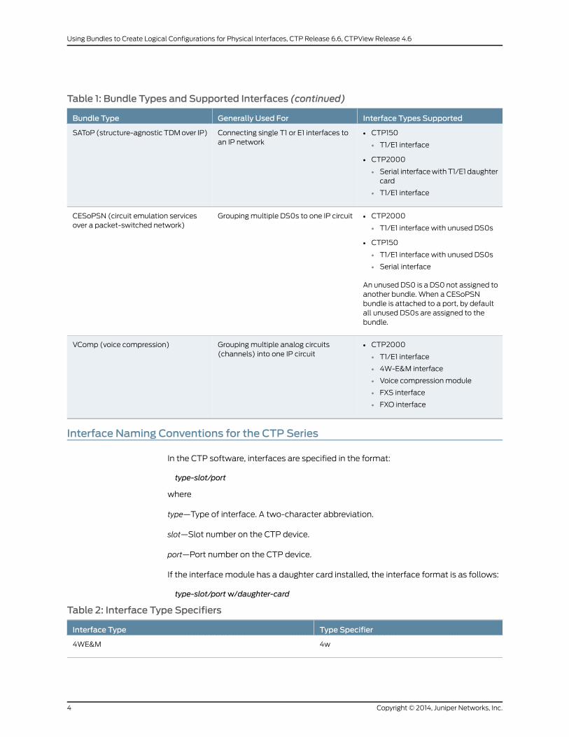
Table 1: Bundle Types and Supported Interfaces (continued)
Interface Types SupportedGenerally Used ForBundle Type
• CTP150
• T1/E1 interface
• CTP2000
• Serial interfacewithT1/E1 daughtercard
• T1/E1 interface
Connecting single T1 or E1 interfaces toan IP network
SAToP (structure-agnostic TDMover IP)
• CTP2000
• T1/E1 interface with unused DS0s
• CTP150
• T1/E1 interface with unused DS0s
• Serial interface
An unused DS0 is a DS0 not assigned toanother bundle. When a CESoPSNbundle is attached to a port, by defaultall unused DS0s are assigned to thebundle.
Groupingmultiple DS0s to one IP circuitCESoPSN (circuit emulation servicesover a packet-switched network)
• CTP2000
• T1/E1 interface
• 4W-E&M interface
• Voice compression module
• FXS interface
• FXO interface
Grouping multiple analog circuits(channels) into one IP circuit
VComp (voice compression)
Interface Naming Conventions for the CTP Series
In the CTP software, interfaces are specified in the format:
type-slot/port
where
type—Type of interface. A two-character abbreviation.
slot—Slot number on the CTP device.
port—Port number on the CTP device.
If the interface module has a daughter card installed, the interface format is as follows:
type-slot/portw/daughter-card
Table 2: Interface Type Specifiers
Type SpecifierInterface Type
4w4WE&M
Copyright © 2014, Juniper Networks, Inc.4
Using Bundles to Create Logical Configurations for Physical Interfaces, CTP Release 6.6, CTPView Release 4.6

Table 2: Interface Type Specifiers (continued)
Type SpecifierInterface Type
4w4WTO
e1E1
fo2W-FXO
fs2W-FSX
irigIRIG
seSerial
t1T1
t1e1T1E1
Serial Multiservice InterfaceModule Overview
CTP bundles are supported on the Serial Multiservice Interfacemodule. CTP bundles on
Multiservice Interface modules can operate with the following modes:
• Audio—Provides single and dual channel audio support for varying quality audio from
8-bit, 8-KHz quality to 8-bit up to 16-bit, 48-KHz quality (CD quality).
• 4WTO—Provides single and dual channel audio support for 8-bit, 8-KHz quality with
squelch support for radio backhaul. In 4WTOmode, theMultiservice Interfacemodule
is interoperable with 4WTO daughter cards.
• IRIG—Enables an interrange instrumentation group time code (IRIG-B) signal to be
transported through an IP network.
• TDC—Provides combined time-correlated support for IRIG/NRZ data for telemetry
applications.
AudioMode
Audio mode provides a high-quality audio (CD quality) interface. Audio mode supports
the following features:
• One or two simultaneous channels.
• Codec sampling rates up to 48 KHz.
• Optional μ-law encoding and decoding.
• Embedded frame requiring no additional bandwidth.
• Configurable output level from 0x to 2x.
• Signaling capability with talk squelch.
5Copyright © 2014, Juniper Networks, Inc.
Chapter 1: Overview of CTP Bundles
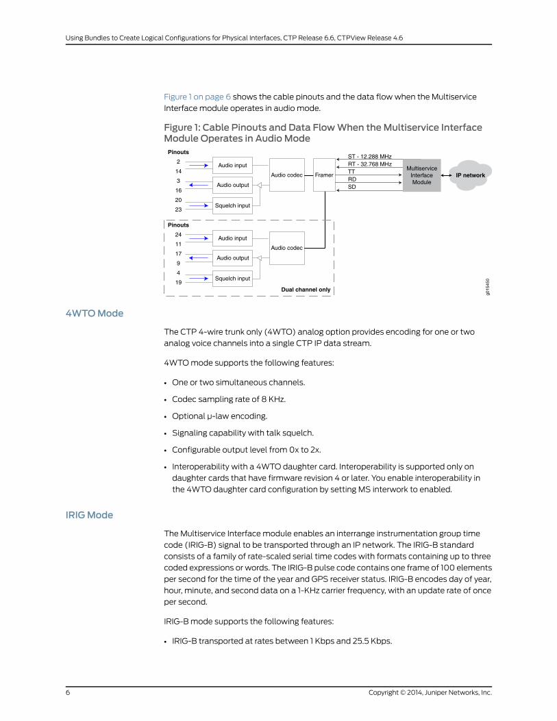
Figure 1 on page 6 shows the cable pinouts and the data flowwhen the Multiservice
Interface module operates in audio mode.
Figure 1: Cable Pinouts and Data FlowWhen theMultiservice InterfaceModule Operates in Audio Mode
Framer IP network
ST - 12.288 MHzRT - 32.768 MHzTTRDSD
Dual channel only
Audio input
Squelch input
Audio codec
Audio output
Pinouts
2
14
3
16
20
23
g015
450
Audio input
Squelch input
Audio codec
Audio output
Pinouts
24
11
17
9
4
19
MultiserviceInterfaceModule
4WTOMode
The CTP 4-wire trunk only (4WTO) analog option provides encoding for one or two
analog voice channels into a single CTP IP data stream.
4WTOmode supports the following features:
• One or two simultaneous channels.
• Codec sampling rate of 8 KHz.
• Optional μ-law encoding.
• Signaling capability with talk squelch.
• Configurable output level from 0x to 2x.
• Interoperability with a 4WTO daughter card. Interoperability is supported only on
daughter cards that have firmware revision 4 or later. You enable interoperability in
the 4WTO daughter card configuration by setting MS interwork to enabled.
IRIGMode
The Multiservice Interface module enables an interrange instrumentation group time
code (IRIG-B) signal to be transported through an IP network. The IRIG-B standard
consists of a family of rate-scaled serial time codes with formats containing up to three
coded expressions or words. The IRIG-B pulse code contains one frame of 100 elements
per second for the time of the year and GPS receiver status. IRIG-B encodes day of year,
hour, minute, and second data on a 1-KHz carrier frequency, with an update rate of once
per second.
IRIG-Bmode supports the following features:
• IRIG-B transported at rates between 1 Kbps and 25.5 Kbps.
Copyright © 2014, Juniper Networks, Inc.6
Using Bundles to Create Logical Configurations for Physical Interfaces, CTP Release 6.6, CTPView Release 4.6
• Configurable output level from 0 to 7.85 volts peak-to-peak based on a 50-ohm
termination.
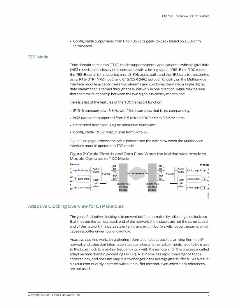
TDCMode
Timedomain correlation (TDC)mode supports special applications inwhich digital data
(NRZ) needs to be closely time correlated with a timing signal (IRIG-B). In TDCmode,
the IRIG-B signal is transported on an8-KHz audio path, and theNRZdata is transported
using RTS/DTR (NRZ input) and CTS/DSR (NRZ output). Circuitry on the Multiservice
Interface module accepts these two streams and combines them into a single digital
data stream that is carried through the IP network in one direction, while making sure
that the time relationship between the two signals is closely maintained.
Here is a list of the features of the TDC transport function:
• IRIG-B transported at 8-KHz with 16-bit samples; that is, no companding.
• NRZ data rates supported from 0.5 KHz to 5000 KHz in 0.5 KHz steps.
• Embedded frame requiring no additional bandwidth.
• Configurable IRIG-B output level from 0x to 2x.
Figure 2 on page 7 shows the cable pinouts and the data flowwhen the Multiservice
Interface module operates in TDCmode.
Figure 2: Cable Pinouts and Data FlowWhen theMultiservice InterfaceModule Operates in TDCMode
Pinouts
3
16
6
22
5
13
STRTTTRDSD
Framer IP network
STRTTTRDSD
Audio input
Clock input
Data input
Pinouts
2
14
20
23
4
19
g015
451
Audiocodec
NRZrate
adapt
FramerAudio output
Clock output
Data output
Audiocodec
NRZrate
adaptMultiservice
InterfaceModule
MultiserviceInterfaceModule
Adaptive Clocking Overview for CTP Bundles
The goal of adaptive clocking is to prevent buffer anomalies by adjusting the clocks so
that they are the same at each end of the network. If the clocks are not the same at each
end of the network, the data rate entering and exiting bufferswill not be the same,which
causes a buffer underflow or overflow.
Adaptive clocking works by gathering information about packets arriving from the IP
network and using that information to determinewhether adjustments need to bemade
to the local clock to maintain frequency lock with the remote end. This process is called
adaptive time domain processing (ATDP). ATDP provides rapid convergence to the
correct clock, and does not vary due to changes in the average jitter buffer fill. As a result,
a circuit continuously operates without a buffer recenter, even when clock references
are not used.
7Copyright © 2014, Juniper Networks, Inc.
Chapter 1: Overview of CTP Bundles

There are two types of adaptive clocking:
• Adaptive clocking with internal clock—Recovers the clock from the user equipment
connected to the remote CTP device and uses it to generate both transmit and receive
timing. All clocking is performed by the DDS, which is initially configured to be locked
to the local system clock. When packets begin to flow between the CTP devices, the
adaptive clock begins time domain analysis of the packets that arrive from the remote
CTP device. Based on this analysis, adjustments are made to the DDS clock to
approximate the frequency of the clock used to create network-bound packets on the
remote CTP. In this way, the local CTP port canmaintain long-term frequency lock
with the remote CTP and pass this clock to the locally connected user equipment.
• AdaptiveclockingwithexternalTXclock—Data received fromthe local user equipment
that isbound to the IPnetwork is clockedusing theCTPexternal user clock (the transmit
timing clock). Data received from the remote CTP device and bound for the interface
is adaptively clocked with the recovered clock from the user equipment connected to
the remoteCTPdevice.Thisconfigurationallows for independentadaptiveconfiguration
in each direction. With this method, the user equipment can send packets into the
networkwith their local clock, and the remote end CTP devices adaptively recover this
clock. This clocking method is useful when the port speed is high or the cable length
between the user equipment and CTP device is large.
RelatedDocumentation
Configuring Adaptive Clocking for CTP Bundles (CTPMenu) on page 104•
• Configuring Adaptive Clocking for CTP Bundles (CTPView) on page 102
Determining Optimal Packet Size for CTP Bundles Overview
You can specify the size of IP packets that are created from data received at the serial
port. The CTP device uses packet size along with the serial interface rate to calculate
the packet rate; that is, the rate that packets are created. Themaximum packet rate is
1500 packets per second.
To determine the optimal packet size, consider the following:
• Bandwidth for transporting serial data
• Packet creation delay
• Performance of the IP network
For example, larger packet sizes aremore bandwidth-efficient, but introducemore delay
during packet creation.
Bandwidth for Transporting Serial Data
When considering bandwidth in relation to deciding packet size, add overhead for both
the Layer 2 encapsulation and the IP header. The IP header comprises 20 bytes; and the
encapsulation overhead varies, but is typically either 6 or 8 bytes on serial links. This
overhead causes smaller packets to be less efficient and result in serial data requiring
more bandwidth.
Copyright © 2014, Juniper Networks, Inc.8
Using Bundles to Create Logical Configurations for Physical Interfaces, CTP Release 6.6, CTPView Release 4.6

Calculate the bandwidth required for a serial bit stream as follows:
IP Bandwidth = [Packet Size (bytes) + 20 (bytes) + 2 (bytes) + EncapsulationOverhead(bytes) x [Packet Rate (pps)] x 8
Packet Creation Delay
Serial data received at theCTP interfacemust be buffered long enough to allowapacket
to be created. The delay to create the packet increases as either the size of the packet
increases or as the rate of the serial interface decreases. Generally, this delay is minimal
except when the rate of the serial interface is low and the packet size is large. We
recommend that you set the packet size to a smaller value for lower-speed serial
interfaces. Table 3 on page 9 provides examples of serial interface packet creation delay
in milliseconds.
Table 3: Packet Creation Delay for Serial Interfaces
Serial Interface Delay (msec)
Packet Size (bytes)
14001024768512256128Interface Rate(Kbps)
175.0128.096.064.032.016.064
87/564.048.032.016.08.0128
43.832.024.016.08.04.0256
10.98.06.04.02.01.01024
7.35.34.02.71.30.71544
5.54.03.02.01.0.52048
Performance of the IP Network
The number of packets created (packet rate) is inversely related to the packet size
configured. For example, smaller packets result in a greater packet rate. When you
configure the packet size, consider the packet-forwarding performance of the attached
router and network. Table 4 on page 9 provides examples of packet rates for various
packet sizes and serial interface rates.
Table 4: Packet Rate for Various Packet Size and Serial Interface Rate Settings
Packet Rate (Packets per Second)
Packet Size (Bytes)
14001024768512256128Interface Rate(Kbps)
5.77.810.415.631.362.564
11.415.620.831.362.5125.0128
9Copyright © 2014, Juniper Networks, Inc.
Chapter 1: Overview of CTP Bundles
Table 4: Packet Rate for Various Packet Size and Serial Interface Rate Settings (continued)
Packet Rate (Packets per Second)
Packet Size (Bytes)
14001024768512256128Interface Rate(Kbps)
22.931.341.762.5125.020.0256
91.4125.0166.7250.0500.01000.01024
137.9188.5251.3277.0753.91507.81544
182.9250.0333.3500.01000.02000.02048
RelatedDocumentation
Configuring IP Parameters for CTP Bundles (CTPMenu) on page 25•
• Configuring IP Parameters for CTP Bundles (CTPView) on page 23
Providing QoS for CTP Bundles by Using Service Type Overview
In IP networks, the IP flow is typically classified based on the Differentiated Services
Code Point (DSCP) setting in the type of service (TOS) byte of the IP header. DSCP is a
scalable solution for classifying flows in a large IP network based on the class of service
desired on specific IP traffic flows.
With the CTP device, you can configure DSCP settings for each circuit’s IP flow. For
example, some circuits could be configured for the expedited forwarding (EF) class.
When the network routers receive this EF-marked flow from the CTP device, they place
the marked traffic into a high-priority queue, enabling this traffic to be serviced before
lower priority traffic. As an EF-marked flow traverses the IP network, routers can use its
classification to provide the flow amore predictable level of performance across the
network
When you configure the service type of a bundle, you specify the ToS byte to be used in
IP headers of packets sent from the CTP device to the IP network. The ToS setting is
applied to circuits created by the bundle for which the service type is configured.
Table5onpage 10 shows themapping for eachDSCPclass and setting to theToSsetting
that you configure as the service type for a bundle. The EF class (ToS setting 184) is
commonly used for circuit traffic.
Table 5: DSCP Classes and Service Type
ToS SettingDSCP SettingDSCP Class
22456CS7
19248CS6
18446EF
Copyright © 2014, Juniper Networks, Inc.10
Using Bundles to Create Logical Configurations for Physical Interfaces, CTP Release 6.6, CTPView Release 4.6
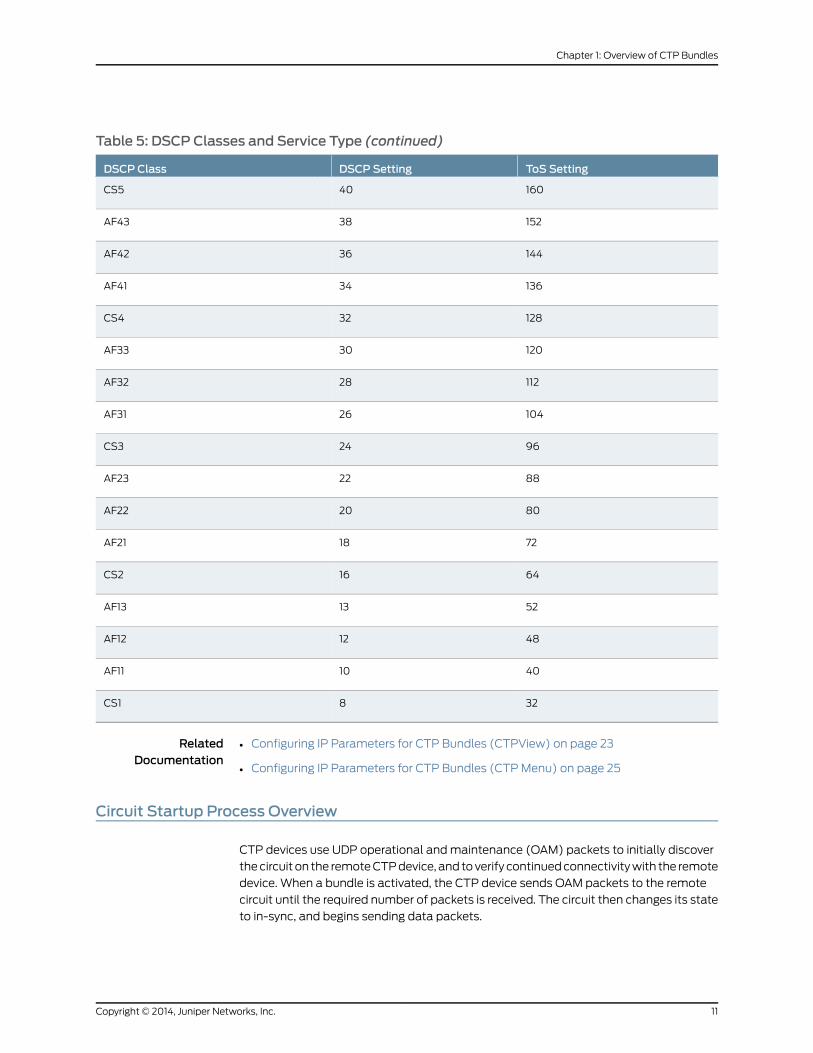
Table 5: DSCP Classes and Service Type (continued)
ToS SettingDSCP SettingDSCP Class
16040CS5
15238AF43
14436AF42
13634AF41
12832CS4
12030AF33
11228AF32
10426AF31
9624CS3
8822AF23
8020AF22
7218AF21
6416CS2
5213AF13
4812AF12
4010AF11
328CS1
RelatedDocumentation
Configuring IP Parameters for CTP Bundles (CTPView) on page 23•
• Configuring IP Parameters for CTP Bundles (CTPMenu) on page 25
Circuit Startup Process Overview
CTP devices use UDP operational andmaintenance (OAM) packets to initially discover
thecircuit on the remoteCTPdevice, and toverify continuedconnectivitywith the remote
device. When a bundle is activated, the CTP device sends OAM packets to the remote
circuit until the required number of packets is received. The circuit then changes its state
to in-sync, and begins sending data packets.
11Copyright © 2014, Juniper Networks, Inc.
Chapter 1: Overview of CTP Bundles
Circuits continue to send OAM packets to the remote device at a configured rate. If the
number of OAM packets that the CTP devices misses reaches a configured number, the
state of the circuit changes from in synchronization to no synchronization.
You can also specify howmany consecutive packets the IP network must drop before
the CTP device restarts the circuit. After the circuit restarts, the CTP devicemust receive
a specified number of in-sequence packets before it transitions the circuit from in-sync
to running.
RelatedDocumentation
Configuring Circuit Startup Parameters for CTP Bundles (CTPView) on page 27•
• Configuring Circuit Startup Parameters for CTP Bundles (CTPMenu) on page 28
Transparent Encoding Overview
• Transparent Encoding Applications and Support Overview on page 12
• How Basic Transparent EncodingWorks on page 12
• Using Phase-Correction FIFO Buffer with Transparent Encoding on page 13
• Using Send Timing (ST) Clocking for Higher Speed Circuits with Transparent
Encoding on page 15
Transparent Encoding Applications and Support Overview
Transparent mode is for unique applications that require the data and clock signals to
be sampledatoneendof a circuit and replicatedat the far end. For example, applications
in which:
• Data rates are low (32 Kbps or less) and rates can vary over time. The sampling jitter
prevents use of higher data rates.
• Data rates are low and fixed and/or low network latency is required.
• Clocks must disappear (transitions stop) periodically during circuit operation.
The transparent encoding scheme is supported only when you have worked with the
Juniper Networks Technical Assistance Center (JTAC) to verify that your application
requires this encoding scheme. Youmay need to use special adapters on the cable to
properly map the data and clock signals to the connector pins that the application uses.
We recommendthat youdonotuse transparentencoding inWANenvironmentsbecause
of its large consumption of bandwidth.
HowBasic Transparent EncodingWorks
There are twomodes of transparent encoding. They are Transparent 4mode (TRANS)
and Transparent 8mode (TRANS8). Transparent 8mode is only supported on CTPOS
release 6.4 and later.
Transparent encodingmode4 samples incoming data on four input signals (SD, TT, RTS,
andDTR), transports these signals across the IP network to the remote end of the circuit,
Copyright © 2014, Juniper Networks, Inc.12
Using Bundles to Create Logical Configurations for Physical Interfaces, CTP Release 6.6, CTPView Release 4.6
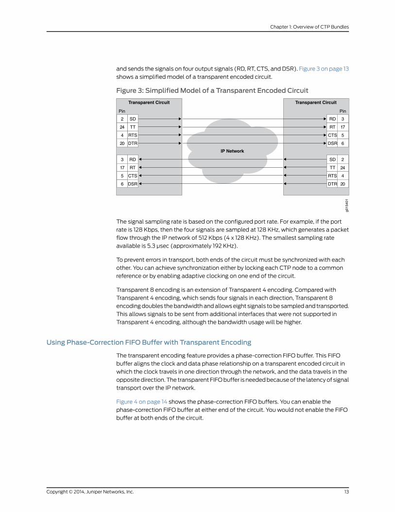
and sends the signals on four output signals (RD, RT, CTS, and DSR). Figure 3 on page 13
shows a simplified model of a transparent encoded circuit.
Figure 3: SimplifiedModel of a Transparent Encoded Circuit
IP Network
g015
401
RD
RT
CTS
DSR
2
24
4
20
SD
TT
RTS
DTR
3
17
5
6
2
24
4
20
SD
TT
RTS
DTR
3
17
5
6
RD
RT
CTS
DSR
Transparent CircuitTransparent Circuit
Pin Pin
The signal sampling rate is based on the configured port rate. For example, if the port
rate is 128 Kbps, then the four signals are sampled at 128 KHz, which generates a packet
flow through the IP network of 512 Kbps (4 x 128 KHz). The smallest sampling rate
available is 5.3 μsec (approximately 192 KHz).
To prevent errors in transport, both ends of the circuit must be synchronized with each
other. You can achieve synchronization either by locking each CTP node to a common
reference or by enabling adaptive clocking on one end of the circuit.
Transparent 8 encoding is an extension of Transparent 4 encoding. Compared with
Transparent 4 encoding, which sends four signals in each direction, Transparent 8
encodingdoubles thebandwidthandallowseight signals tobesampledand transported.
This allows signals to be sent from additional interfaces that were not supported in
Transparent 4 encoding, although the bandwidth usage will be higher.
Using Phase-Correction FIFO Buffer with Transparent Encoding
The transparent encoding feature provides a phase-correction FIFO buffer. This FIFO
buffer aligns the clock and data phase relationship on a transparent encoded circuit in
which the clock travels in one direction through the network, and the data travels in the
oppositedirection.The transparentFIFObuffer is neededbecauseof the latencyof signal
transport over the IP network.
Figure 4 on page 14 shows the phase-correction FIFO buffers. You can enable the
phase-correction FIFO buffer at either end of the circuit. You would not enable the FIFO
buffer at both ends of the circuit.
13Copyright © 2014, Juniper Networks, Inc.
Chapter 1: Overview of CTP Bundles

Figure 4: Transparent Encoding with Phase-Correction FIFO Buffers
Transparent CircuitTransparent Circuit
DTE DCE
g015
406
RD
RT
CTS
DSR
2
24
4
20
SD
TT
RTS
DTR
3
17
5
6
2
24
4
20
SD
TT
RTS
DTR
3
17
5
6
RD
RT
CTS
DSR
Pin Pin
FIFO FIFO
Figure 5 on page 14 shows the paths of the clock and data through the phase-correction
FIFO buffer that is enabled on the transparent circuit on the right.
• The clock enters the network from the DCE, goes to the DTE, and then clocks data into
the network on the DTE. The clock is also looped back on the DTE to enter the network
in phase with the data as it travels from the DTE to the DCE.
• The data enters the FIFO buffer in phase with the clock passing through the network
from the DTE to the DCE, while data is clocked out of the FIFO buffer with the clock
that entered the network from the DCE, which is in phase with the user clock.
Figure 5: Clock and Data Paths with Transparent Phase-Correction FIFOBuffers
Transparent CircuitTransparent Circuit
DTE DCE
g015
402
RD
RT
CTS
DSR
2
24
4
20
SD
TT
RTS
DTR
3
17
5
6
2
24
4
20
SD
TT
RTS
DTR
3
17
5
6
RD
RT
CTS
DSR
Red = clockBlue = data
Pin Pin
FIFO FIFO
Like inTRANSencoding, youcanuse the 16bit phasecorrectionFIFO inTRANS8encoding
to accommodate the problems that can be caused by the high latency in the circuit
whether or not the remote DCE device can accept TT input or not.
When the customerDCEdevice can support theTTsignal returnedby theDTE, thephase
correction FIFO is not needed. The DCE transmit clock (ST) is sampled and carried
Copyright © 2014, Juniper Networks, Inc.14
Using Bundles to Create Logical Configurations for Physical Interfaces, CTP Release 6.6, CTPView Release 4.6

downstream to the DTE, where it is used to generate the upstreamdata that is sent back
to the customer DCE. This clock data is also sent as theDTE transmit clock (TT) to travel
along with the data in phase. When these signals get back to the customer DCE device,
they are still in phase (same delay through the network), so the customer DCE can use
the TT signal to recover the transmit data on the SD lead.
Consider a scenario in which the customer's upstream DCE does not use the TT signal
for capturing upstream data, and instead uses the ST clock. Here, due to the latency of
the ST clock traveling downstream and the time taken for the return trip of the data, it
is difficult to ensure error-free data transport. In such a scenario, you can use phase
correction FIFO to ensure error-free data transport.
The SD or TT clock and data signals get back to the upstream CTP device, where the
data is clocked into the FIFO using the TT clock, which is in phase. This data is clocked
out of the FIFOusing the upstreamSTclock, and the data is realigned to be in phasewith
the ST clock.
Using Send Timing (ST) Clocking for Higher Speed Circuits with Transparent Encoding
When the relationship between the clock and the data signals is critical, you can use ST
clockingwith transparent encoding topreventdelayand jitter inCTP2000seriesdevices,
making it possible to carry higher speed circuits in transparent mode.
Figure 6 on page 16 shows the issue of delay and jitter where a transparent encoded
circuit connects a DCE to a DTE. The circuit is set up as follows:
• The high-speed clock and data lines (shown in red) are aligned by a FIFO buffer at the
DCE.
• The signaling leads (shown in blue) are passed end-to-endwithout going through the
FIFO buffer. The signaling paths that carry non-timing-critical signals are subject to
delay and jitter.
The problem is that when a FIFO buffer is used at one end of the circuit, an additional
clock path from the DCE to the DTE is needed to carry a clock to the DTE so that it can
returnaDTE-to-DCEclock that is inphasewith thedata. ThisDTE-to-DCEclock is needed
to clock the FIFO input. Normally, one of the signal lead paths carries this transmit clock.
However, when the circuit is running at speeds above 32k, the delay and jitter on these
paths make these signal choices nonoptimal.
15Copyright © 2014, Juniper Networks, Inc.
Chapter 1: Overview of CTP Bundles

Figure 6: High-Speed and Low-Speed Paths with Transparent Encoding
g015
403
Red = High-speed clock and data linesBlue = Signaling lead
DCE
RTS
CTS
DTR
DSR
DTE
DTR
DSR
RTS
CTS
Transparent Circuit
FIFO
Delay/Jitter
Delay/Jitter
Delay/Jitter
Delay/Jitter
Transparent Circuit
To solve the issue of delay and jitter associated with the signaling leads, you can use the
ST interface signal to feed or sink the RTS-to-CTS signal path. By using the ST interface
signal instead of the RTS-to-CTS signal path, delay and jitter are removed from that
signal path. Figure 7 on page 16 shows a transparent-encoded circuit with the additional
ST functionality:
• At the DCE, the RTS-to-CTS signal path is configured to use ST (as an input from the
DCE) to feed that signal path through the network.
• At the DTE, that signal is placed onto the ST lead, which is configured as an output.
Figure 7: Transparent Encoding Using ST Clocking
IP Network
g015
404
Red = Send timing (ST) pathBlue = Send data (SD path
3
17
4
5
7
3
17
4
6
6
20
7
1 1
20
2
24
5
20
7
3
17
4
5
6
20
7
1 1
6
3
17
4
5
6
20 DTR
RTS
RD
DSR
RT
CTS
2
24
17
4
5
6
20
SD
DTR
TT
RTS
DSR
RT
CTS
Transparent Circuit
10d/
5j
10d/
5j
DTE
3
17
4
5
6
20DTR
DSR
RTS
CTS
DCE
3
17
4
5
6
20
RTS
CTS
DTR
DSR
Adapter Adapter
2
24
15
2
15
3 2
1515
2
24
SD 3RD
1515
2
15
2
15FIFO
FIFO
ST ST
TT
Transparent Circuit
Copyright © 2014, Juniper Networks, Inc.16
Using Bundles to Create Logical Configurations for Physical Interfaces, CTP Release 6.6, CTPView Release 4.6
When you configure transparent encoding to use the ST lead instead of RTS/CTS, you
can specify whether or not ST is an input lead.
TDM/TDC Encoding Overview
The time domain correlation (TDC) feature uses time division multiplexing (TDM) to
interleavemultipledata typesonserial ports so that theCTPdevicecanbond twocircuits
into a single data stream. Doing so allows the CTP device to carry two independent data
streams on the same path through the IP network . Out of each set of 32 bits in the IP
data stream, you can designate a certain number of bits for TDM functions.
The TDM/TDC feature is commonly used for telemetry applications, and is supported
on CTP2000 serial interfaces.
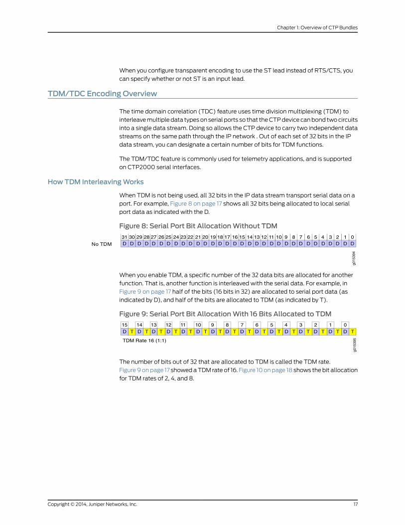
HowTDM InterleavingWorks
When TDM is not being used, all 32 bits in the IP data stream transport serial data on a
port. For example, Figure 8 on page 17 shows all 32 bits being allocated to local serial
port data as indicated with the D.
Figure 8: Serial Port Bit AllocationWithout TDM
g015
394
012345678911 1013 1215 1417 1619 1821 2023 2225 2427 2629 2830D D D D D D D D D D D D D D D D D D D D D D D D D D D D D DD
31DNo TDM
When you enable TDM, a specific number of the 32 data bits are allocated for another
function. That is, another function is interleaved with the serial data. For example, in
Figure 9 on page 17 half of the bits (16 bits in 32) are allocated to serial port data (as
indicated by D), and half of the bits are allocated to TDM (as indicated by T).
Figure 9: Serial Port Bit AllocationWith 16 Bits Allocated to TDM
g015
395
D D D D D D D D D D D D D D D D
TDM Rate 16 (1:1)
012345678911 1013 1215 14TTTTTTTTTTTTTTTT
The number of bits out of 32 that are allocated to TDM is called the TDM rate.
Figure9onpage 17 showedaTDM rate of 16. Figure 10onpage 18 shows thebit allocation
for TDM rates of 2, 4, and 8.
17Copyright © 2014, Juniper Networks, Inc.
Chapter 1: Overview of CTP Bundles
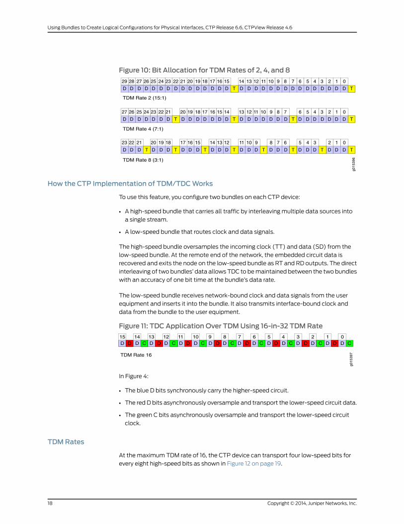
Figure 10: Bit Allocation for TDMRates of 2, 4, and 8
g015
396
D D D D D D D D D D D D D D D D D D D D D D D D D D D D D D
D D D D D D D D D D D D D D D D D D D D D D D D D D D D
D D D D D D D D D D D D D D D D D D D D D D D D
012345678911 1013 1215 1417 1619 1821 2023 2225 2427 2629 28
012345678911 1013 1215 1417 1619 1821 2023 2225 2427 26
012345678911 1013 1215 1417 1619 1821 2023 22
TTTTTTTT
TTTT
TT
TDM Rate 2 (15:1)
TDM Rate 4 (7:1)
TDM Rate 8 (3:1)
How the CTP Implementation of TDM/TDCWorks
To use this feature, you configure two bundles on each CTP device:
• A high-speed bundle that carries all traffic by interleaving multiple data sources into
a single stream.
• A low-speed bundle that routes clock and data signals.
The high-speed bundle oversamples the incoming clock (TT) and data (SD) from the
low-speed bundle. At the remote end of the network, the embedded circuit data is
recovered and exits the node on the low-speed bundle as RT and RD outputs. The direct
interleaving of two bundles’ data allows TDC to bemaintained between the two bundles
with an accuracy of one bit time at the bundle’s data rate.
The low-speed bundle receives network-bound clock and data signals from the user
equipment and inserts it into the bundle. It also transmits interface-bound clock and
data from the bundle to the user equipment.
Figure 11: TDC Application Over TDMUsing 16-in-32 TDMRate
g015
397
D D CD D D D D D D D D D D D D D DD C D C D C D C D C D C D C012345678911 1013 1215 14
TDM Rate 16
In Figure 4:
• The blue D bits synchronously carry the higher-speed circuit.
• The red D bits asynchronously oversample and transport the lower-speed circuit data.
• The green C bits asynchronously oversample and transport the lower-speed circuit
clock.
TDMRates
At the maximum TDM rate of 16, the CTP device can transport four low-speed bits for
every eight high-speed bits as shown in Figure 12 on page 19.
Copyright © 2014, Juniper Networks, Inc.18
Using Bundles to Create Logical Configurations for Physical Interfaces, CTP Release 6.6, CTPView Release 4.6

Figure 12: High-Speed and Low-Speed Ratio at theMaximumTDMRateof 16
g015
398
D D CD D D D D D D D D D D D D D DD C D C D C D C D C D C D C012345678911 1013 1215 14
HIGH SPEED CLK
LOW SPEED CLK
TDM Rate 16
If the ratio of circuit speeds is higher than 8:1, then you can use lower TDM rates, which
allocates fewer bits for the TDM function and therefore uses less network bandwidth.
Figure 13 on page 19 shows other supported TDM rates as applied to TDC.
Figure 13: TDMRates as Applied to TDC
D D CD D D D D D D D D D D D D D D D D D D D D D D D D D D D D
D D CD D D D D D D D D D D D D D D D D D D D D D D D D D D
TDM Rate 2
D C
D D CD D D D D D D D D D D D D D D D D D D D D D DD C D C D C
012345678911 1013 1215 1417 1619 1821 2023 2225 2427 2629 28
012345678911 1013 1215 1417 1619 1821 2023 2225 2427 26
012345678911 1013 1215 1417 1619 1821 2023 22
g015
399
TDM Rate 4
TDM Rate 8
TDMHigh-Speed and Low-Speed Ports
Touse theTDM/TDC feature, youconfigureahigh-speedbundleanda low-speedbundle
as follows:
• The high-speed bundle is configured on an even-numbered port, and it is configured
for TDM encoding because it interleaves multiple data sources into a single stream.
• The low-speedbundle is configured on anodd-numbered port that is one port number
higher (N+1) than the high-speed port. It is configured for TDM/TDC clocking because
it routes clock and data signals.
Figure 14 on page 20 shows a high-speed port and low-speed port.
19Copyright © 2014, Juniper Networks, Inc.
Chapter 1: Overview of CTP Bundles
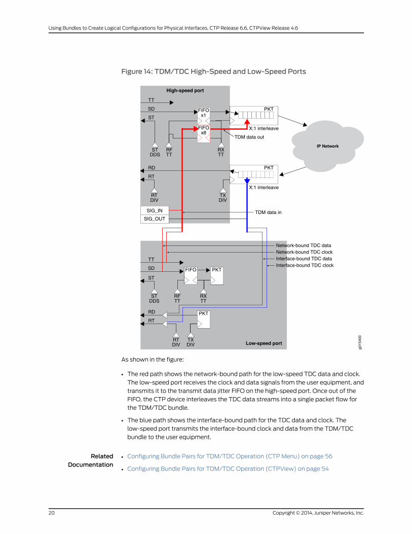
Figure 14: TDM/TDCHigh-Speed and Low-Speed Ports
g015
400
Low-speed port
High-speed port
RT
RD
SD
TT
FIFOx1
PKT
RXTT
ST
RT
RD
SD
TT
RFTT
STDDS
X:1 interleave
X:1 interleave
TDM data in
TDM data out
Network-bound TDC dataNetwork-bound TDC clockInterface-bound TDC dataInterface-bound TDC clock
IP Network
TXDIV
RTDIV
PKT
SIG_IN
SIG_OUT
FIFOx8
ST
STDDS
PKT
PKT
RTDIV
TXDIV
RFTT
RXTT
FIFO
As shown in the figure:
• The red path shows the network-bound path for the low-speed TDC data and clock.
The low-speed port receives the clock and data signals from the user equipment, and
transmits it to the transmit data jitter FIFO on the high-speed port. Once out of the
FIFO, the CTP device interleaves the TDC data streams into a single packet flow for
the TDM/TDC bundle.
• The blue path shows the interface-bound path for the TDC data and clock. The
low-speed port transmits the interface-bound clock and data from the TDM/TDC
bundle to the user equipment.
RelatedDocumentation
• Configuring Bundle Pairs for TDM/TDC Operation (CTPMenu) on page 56
• Configuring Bundle Pairs for TDM/TDC Operation (CTPView) on page 54
Copyright © 2014, Juniper Networks, Inc.20
Using Bundles to Create Logical Configurations for Physical Interfaces, CTP Release 6.6, CTPView Release 4.6
CHAPTER 2
Configuring CTP Bundles
• Adding a Bundle (CTPView) on page 22
• Adding a Bundle (CTPMenu) on page 23
• Configuring IP Parameters for CTP Bundles (CTPView) on page 23
• Configuring IP Parameters for CTP Bundles (CTPMenu) on page 25
• Configuring Circuit Startup Parameters for CTP Bundles (CTPView) on page 27
• Configuring Circuit Startup Parameters for CTP Bundles (CTPMenu) on page 28
• Configuring theCTPBundleDataPacketProtocolandOAMPort (CTPMenu)onpage29
• Ethernet Media Configuration Overview on page 29
• Displaying Ethernet Media Information (CTPMenu) on page 30
• Configuring Ethernet Media (CTPMenu) on page 30
• Configuring the Direction of the Circuit (CTPView) on page 32
• Configuring the Direction of the Circuit (CTPMenu) on page 32
• Configuring Virtual IP Parameters for CTP Bundles (CTPView) on page 33
• Configuring Virtual IP Parameters for CTP Bundles (CTPMenu) on page 34
• Configuring the Missing Packet Fill Pattern for CTP Bundles (CTPView) on page 35
• Configuring the Missing Packet Fill Pattern for CTP Bundles (CTPMenu) on page 36
• Configuring IP Forwarding for CTP Bundles (CTPView) on page 36
• Configuring IP Forwarding for CTP Bundles (CTPMenu) on page 37
• Configuring Signaling for CTP Bundles (CTPView) on page 39
• Configuring Signaling for CTP Bundles (CTPMenu) on page 43
• Configuring Serial Port Parameters for CTP Bundles (CTPView) on page 47
• Configuring Serial Port Parameters for CTP Bundles (CTPMenu) on page 49
• Configuring Transparent Encoding for CTP Bundles (CTPMenu) on page 53
• Configuring Bundle Pairs for TDM/TDC Operation (CTPView) on page 54
• Configuring Bundle Pairs for TDM/TDC Operation (CTPMenu) on page 56
• Configuring T1 and E1 Port Parameters for CTP Bundles (CTPView) on page 59
• Configuring T1 and E1 Port Parameters for CTP Bundles (CTPMenu) on page 61
• Configuring Multiservice Port Parameters for CTP Bundles (CTPView) on page 64
21Copyright © 2014, Juniper Networks, Inc.
• Configuring Multiservice Port Parameters for CTP Bundles (CTPMenu) on page 69
• Configuring 4WTO Port Parameters for CTP Bundles (CTPView) on page 76
• Configuring 4WTO Port Parameters for CTP Bundles (CTPMenu) on page 79
• Configuring IRIG-B Port Parameters for CTP Bundles (CTPView) on page 81
• Configuring IRIG-B Port Parameters for CTP Bundles (CTPMenu) on page 83
• Configuring Advanced Port Options for CTP Bundles (CTPView) on page 85
• Configuring Advanced Port Options for CTP Bundles (CTPMenu) on page 86
• Configuring Port Mirroring for CTP Bundles (CTPView) on page 87
• Configuring Port Mirroring for CTP Bundles (CTPMenu) on page 88
• Configuring Cryptographic Resynchronization (Crypto Resync) on page 90
• Selecting the Type of Clocking on Serial Ports for CTP Bundles (CTPView) on page 91
• Selecting theType of Clocking onSerial Ports for CTPBundles (CTPMenu) onpage93
• Configuring Custom Clocking for CTP Bundles (CTPView) on page 96
• Configuring Custom Clocking for CTP Bundles (CTPMenu) on page 99
• Configuring Adaptive Clocking for CTP Bundles (CTPView) on page 102
• Configuring Adaptive Clocking for CTP Bundles (CTPMenu) on page 104
• Network Node Reference Overview on page 105
• Configuring NetRef for Adaptive Bundle Operation on page 107
• Configuring NetRef for Primary or Backup Operation on page 108
Adding a Bundle (CTPView)
Before you begin:
• Log in to the CTPView software at least at the Net_Admin level.
• Connect theCTPViewserver to theCTPdevice forwhichyouwant toconfigurebundles.
To add a bundle using CTPView:
1. In the side pane, select Bundle > Configuration.
2. Run your mouse over theOpen Add Bundles Display bar.
3. UnderNewBndl Number, select a bundle number.
4. Under the type of bundle you want to add, select a source port and click the button
for the type of bundle.
Before you create a VComp bundle, youmust ensure that the CTP system has a
VComp card installed. The CTP systemdisplays awarningmessage if no VComp card
is installed. If you create a VComp bundle on a CTP system that does not have a
VComp card installed and try to activate it, the CTP system displays the following
warning message:
There is not enough system DSP resource for the bundle.
Copyright © 2014, Juniper Networks, Inc.22
Using Bundles to Create Logical Configurations for Physical Interfaces, CTP Release 6.6, CTPView Release 4.6
The bundle remains disabled until you install a VComp card and activate the bundle
again. If you remove the VComp card from a CTP system that has an active VComp
bundle, the Run state of the VComp bundle changes to MisCfg.
5. Enter the parameters and click Click to Submit Bundle AND Port Changes.
Adding a Bundle (CTPMenu)
To add a bundle using the CTPMenu:
1. From the CTPMain Menu, select 1) Bundle Operations.
2. Select the type of bundle that you want to configure.
Before you create a VComp bundle, youmust ensure that the CTP system has a
VComp card installed. The CTP systemdisplays awarningmessage if no VComp card
is installed. If you create a VComp bundle on a CTP system that does not have a
VComp card installed and try to activate it, the CTP system displays the following
warning message:
There is not enough system DSP resource for the bundle.
The bundle remains disabled until you install a VComp card and activate the bundle
again. If you remove the VComp card from a CTP system that has an active VComp
bundle, the Run state of the VComp bundle changes to MisCfg.
3. Enter add to add a new bundle.
4. Select the port you want to attach the bundle to.
Configuring IP Parameters for CTP Bundles (CTPView)
The CTP software uses the IP parameters to create IP packets.
Before you begin:
• Log in to the CTPView software at least at the Net_Admin level.
• Connect theCTPViewserver to theCTPdevice forwhichyouwant toconfigurebundles.
To configure IP parameters for CTP bundles using CTPView:
1. In the side pane, select Bundle > Configuration.
2. Run your mouse over the Display and Select an Existing Bundle bar.
3. In the table of bundles, select the bundle that you want to modify.
4. Under Bundle Options, configure the parameters as described in Table 6 on page 24and click Click to Submit Bundle AND Port Changes.
23Copyright © 2014, Juniper Networks, Inc.
Chapter 2: Configuring CTP Bundles

Table 6: CTP Bundle IP Parameter Settings in CTPView
Your ActionFunctionField
Type a description for the bundle.Specifies identifying information about the bundle.
You can use the bundle description as the search criteria when yousearch for bundles from the network monitoring page.
BundleDescription
Select DISABLED or ACTIVE.Specifies whether the bundle is active or disabled.State
In the first field, select the CTPdevice.
In the second field, select aninterface on the CTP device.
Specifies the name and IP address of the remote CTP device.RemoteAddress
Enteranumber from0through249.Specifies the bundle to connect to on the remote CTP device.Remote CircuitID
Enteranumber from0through249.Specifies the bundle on the local CTP device.Local Circuit ID
Select a packet size.
For CTP150 devices, the availablepacket size is 8 through 1456.
ForCTP2000devices, theavailablepacket size is 4 through 1456.
Specifies the size of IP packets that are created from data received atthe serial port.
The CTP device makes sure that the combination of packet size anddata rate does not result in a packet rate that exceeds 1200 packetsper second.
Packet Size
Enter a number from0.001 through9999.000milliseconds.
Specifies the minimum average buffer size. Use a value that is greaterthan the expected jitter and less than the Buffer Set parameter.
Theminimumbuffer ensures that thebufferdoesnotbecometoosmallbecause of timing variances between the local and remote serialinterfaces.
Theentirebuffer is available for accommodatingandsmoothingpacketdelay jitter, regardless of the minimum buffer setting.
Min Buffer
Enter a number from0.001 through9999.000milliseconds.
Specifies the buffer size when the circuit enters a running state. Thisvalue must be large enough to accommodate the anticipated packetdelay, and it must be set to a value greater than theminimum buffersize and lower than themaximum buffer size.
Buffer Set
Enter a number from0.001 through9999.000milliseconds.
Specifies the maximum buffer size. Themaximum buffer ensures thatthe buffer does not become too large due to timing variances betweenthe local and remote serial interfaces. If the buffer size exceeds themaximum buffer size, the buffer is recentered to the Buffer Set value.
Periodic buffer recenters are not expected. If you notice recenters, werecommend that you verify the reference to the CTP (if used) or thatyou configure one port with adaptive clocking.
Max Buffer
Copyright © 2014, Juniper Networks, Inc.24
Using Bundles to Create Logical Configurations for Physical Interfaces, CTP Release 6.6, CTPView Release 4.6

Table 6: CTP Bundle IP Parameter Settings in CTPView (continued)
Your ActionFunctionField
Enteranumber from0through255.Specifies the ToS byte to be used in the IP headers of packets sentfrom the CTP device to the IP network.
For a mapping of ToS byte values to DSCP classes and settings, see“Providing QoS for CTP Bundles by Using Service Type Overview” onpage 10.
You do not need to set the ToS value to the same value on local andremote bundles.
Service Type
Enteranumber from0through255.Specifies the maximum number of router hops that a packet cantraverse. The CTP device sets the TTL value in IP packets that it sendsto the IP network. The IP network does not alter or optimize the packetrouting based on the TTL setting. You do not need to set the same TTLvalue on local and remote ports.
Time to Live
RelatedDocumentation
Determining Optimal Packet Size for CTP Bundles Overview on page 8•
• Providing QoS for CTP Bundles by Using Service Type Overview on page 10
Configuring IP Parameters for CTP Bundles (CTPMenu)
The CTP software uses the IP parameters to create IP packets.
Before you begin:
• Disable the bundle before youmodify the bundle options.
To configure IP parameters for CTP bundles using the CTPMenu:
1. From the CTPMain Menu, select 1) Bundle Operations.
2. Select 1) CTP.
3. Select a bundle from the list.
If you select an active bundle, you are prompted to disable the bundle before
configuring it.
4. Select 2) Config to configure the bundle.
5. Configure options 1 through 9 as described in Table 7 on page 25.
Table 7: CTP Bundle IP Parameter Settings in the CTPMenu
Your ActionFunctionField
Enter the address of the remoteCTP device.
Specifies the name and IP address of the remote CTP device.RemoteAddress
Enter a number from 0 through249.
Specifies the bundle to connect to on the remote CTP device.Remote CircuitID
25Copyright © 2014, Juniper Networks, Inc.
Chapter 2: Configuring CTP Bundles
Table 7: CTP Bundle IP Parameter Settings in the CTPMenu (continued)
Your ActionFunctionField
Enter a number from 0 through249.
Specifies the bundle on the local CTP device.Local Circuit ID
For CTP150 devices, enter anumber from 8 through 1456.
For CTP2000 devices, enter anumber from 4 through 1456.
Specifies the size of IP packets that are created from data received atthe serial port.
TheCTPdevicemakes sure that the combination of packet size anddatarate does not result in a packet rate that exceeds 1200 packets persecond.
Packet Size
Enter a number from 0.001through 9999.000milliseconds.
Specifies the minimum average buffer size. Use a value that is greaterthan the expected jitter and less than the Pkt Buffer Set parameter.
Theminimumbuffer ensures that the buffer does not become too smallbecause of timing variances between the local and remote serialinterfaces.
The entire buffer is available for accommodating and smoothing packetdelay jitter, regardless of the minimum buffer setting.
Min Buffer
Enter a number from 0.001through 9999.000milliseconds.
Specifies thebuffer sizewhen thecircuit enters a running state. This valuemust be large enough to accommodate the anticipated packet delay,and it must be set to a value greater than theminimum buffer size andlower than themaximum buffer size.
Pkt Buffer Set
Enter a number from 0.001through 9999.000milliseconds.
Specifies the maximum buffer size. Themaximum buffer ensures thatthe buffer does not become too large due to timing variances betweenthe local and remote serial interfaces. If the buffer size exceeds themaximumbuffer size, the buffer is recentered to the Pkt Buffer Set value.
Periodic buffer recenters are not expected. If you notice recenters, werecommend that you verify the reference to the CTP (if used) or that youconfigure one port with adaptive clocking.
Max Buffer
Enter a number from 0 through255.
Specifies the ToS byte to be used in the IP headers of packets sent fromthe CTP device to the IP network.
For a mapping of ToS byte values to DSCP classes and settings, see“Providing QoS for CTP Bundles by Using Service Type Overview” onpage 10.
You do not need to set the ToS value to the same value on local andremote bundles.
Service Type
Enter a number from 0 through255.
Specifies themaximumnumberof router hops thatapacket can traverse.The CTP device sets the TTL value in IP packets that it sends to the IPnetwork. The IP network does not alter or optimize the packet routingbased on the TTL setting. You do not need to set the same TTL value onlocal and remote ports.
Time to Live
Typeadescription for thebundle.Specifies identifying information about the bundle.
Youcanuse thebundledescriptionas thesearchcriteriawhenyousearchfor bundles from the network monitoring page.
BundleDescription
Copyright © 2014, Juniper Networks, Inc.26
Using Bundles to Create Logical Configurations for Physical Interfaces, CTP Release 6.6, CTPView Release 4.6

RelatedDocumentation
Providing QoS for CTP Bundles by Using Service Type Overview on page 10•
Configuring Circuit Startup Parameters for CTP Bundles (CTPView)
This topic describes how toconfigure advancedoptions that are related to circuit startup.
Set these parameters to the same values on the local and remote CTP devices.
Before you begin:
• Log in to the CTPView software at least at the Net_Admin level.
• Connect theCTPViewserver to theCTPdevice forwhichyouwant toconfigurebundles.
To configure circuit startup parameters for CTP bundles using CTPView:
1. In the side pane, select Bundle > Configuration.
2. Run your mouse over the Display and Select an Existing Bundle bar.
3. In the table of bundles, select the bundle that you want to modify.
4. Under Bundle Options, select Advanced Options Show to display advanced
parameters and configure the parameters as described in Table 8 on page 27.
5. Click Click to Submit Bundle AND Port Changes.
Table 8: CTP Bundle Advanced Options Parameter Settings for Circuit Startup in CTPView
Your ActionFunctionField
Enter a number from 1through 255.
Specifies the number of OAM packets per second that the circuitsends to the remote CTP device.
OAM Packet Spacing
Enter a number from 1through 255.
Specifies the number of OAM packets that the circuit must receivebefore the state moves from no synchronization to insynchronization.
OAM Packets for Sync
Enter a number from 1through 255.
Specifies the number of receivedOAMpackets that theCTPdevicemissesbefore the stateof thecircuitmoves from in synchronizationto no synchronization.
OAM Packets for SyncLoss
Enter a number from 1through 64.
Specifies howmany consecutive circuit packets the IP networkmust drop before the CTP device restarts the circuit.
We recommend that you set the parameter to a larger value whenthe IPnetworkusespacket-encryptingdevices.Thesedevicescausemomentary interruption in packet flows when encryption keys areupdated.
Consecutive Pkt Loss ToStarvation
Enter a number from 1through 64.
Specifies the number of in-sequence packets the CTP devicemustreceive after a starvation before the circuit transitions from in-syncto running.
InSync Pkts AfterStarvation
RelatedDocumentation
Circuit Startup Process Overview on page 11•
27Copyright © 2014, Juniper Networks, Inc.
Chapter 2: Configuring CTP Bundles

Configuring Circuit Startup Parameters for CTP Bundles (CTPMenu)
This topic describes how toconfigure advancedoptions that are related to circuit startup.
Set these parameters to the same values on the local and remote CTP devices.
Before you begin:
• Disable the bundle before youmodify the bundle options.
To configure circuit startup parameters using the CTPMenu:
1. From the CTPMain Menu, select 1) Bundle Operations.
2. Select 1) CTP.
3. Select a bundle from the list.
If you select an active bundle, you are prompted to disable the bundle before
configuring it.
4. Select 2) Config.
5. Select 10) Advanced Options.
6. Configure options 4, 5, 6, 7, and 8 as described in Table 9 on page 28.
Table9: CTPBundleAdvancedOptionsParameterSettings forCircuit Startup in theCTPMenu
Your ActionFunctionField
Enteranumber from1 through64.
Specifieshowmanyconsecutivecircuit packets the IPnetworkmustdrop before the CTP device restarts the circuit.
We recommend that you set the parameter to a larger value whenthe IPnetworkusespacket-encryptingdevices.Thesedevicescausemomentary interruption in packet flows when encryption keys areupdated.
Consecutive pkts loss tostarve
Enteranumber from1 through64.
Specifies the number of in-sequence packets the CTP devicemustreceive after a starvation before the circuit transitions from in-syncto running.
In sequence pkts afterstarve
Enteranumber from1 through255.
Specifies the number of OAM packets per second that the circuitsends to the remote CTP device.
OAM Chan Rate(pkt/sec)
Enteranumber from1 through255.
Specifies the number of OAM packets that the circuit must receivebefore the state moves from no synchronization to insynchronization.
OAM pkts for Sync
Enteranumber from1 through255.
Specifies the number of receivedOAMpackets that the CTP devicemisses before the state of the circuitmoves from in synchronizationto no synchronization.
OAM pkts for Sync Loss
RelatedDocumentation
Circuit Startup Process Overview on page 11•
Copyright © 2014, Juniper Networks, Inc.28
Using Bundles to Create Logical Configurations for Physical Interfaces, CTP Release 6.6, CTPView Release 4.6
Configuring the CTP Bundle Data Packet Protocol and OAMPort (CTPMenu)
To configure the CTP Bundle Data Packet Protocol using the CTPMenu:
1. From the Main Menu, select 5) Node Operations.
2. Select 3) Configure network settings.
3. Select 6) CTP Bndl Data pkt protocol. The following warning message is displayed.
****** You are about to modify a system parameter that will require*** a system reboot when complete.****** If you decide to continue, the system will automatically*** reboot upon leaving these menus.****** Note: If these parameters are changed incorrectly,*** system may not be reachable via the network*** after the system reboots.*** Are you sure? y[n]:
4. When prompted, specify a value for the protocol ID for data packets in the range
2-254. The default value is 46.
To configure a CTP Bndl OAM port (IPv6):
1. From the Main Menu, select 5) Node Operations.
2. Select 3) Configure network settings.
3. Select 7) CTP Bndl OAM port (IPv6).
4. When prompted, specify a port number for OAM packets in the range 2 through 254.
The default value is 16.
Ethernet Media Configuration Overview
You can configure the CTP Ethernet media to autonegotiate and set the speed to either
100 or 10 Mbps. By default, autonegotiation is enabled and the speed is to 1000Mbps.
If youchoose todisableautonegotiation, the systemprompts you toconfigure thedesired
speed.
The Ethernet configurations on CTPmust match the configuration of the connected
router or switch. Mismatched configurations, such as setting the CTP system to
autonegotiate and the router to full duplex, will result in amisconfiguration and dropped
packets. Youmust disable Cisco Discovery Protocol on the Fast Ethernet port connected
to the CTP system.
Table 10 on page 30 lists the valid Ethernetmedia configuration settings that CTPSeries
supports.
29Copyright © 2014, Juniper Networks, Inc.
Chapter 2: Configuring CTP Bundles

Table 10: Valid Ethernet Media Configuration Settings for CTP
MTU (up to 1500)Mode (Duplex)Autoneg StatusSpeed
anyFullON1000
anyFullOFF100
anyFullOFF10
NOTE: The CTP system supports only full duplexmode.
RelatedDocumentation
Configuring Ethernet Media (CTPMenu) on page 30•
• Displaying Ethernet Media Information (CTPMenu) on page 30
Displaying Ethernet Media Information (CTPMenu)
This topic describes how to display the supported link modes (speed and duplex) and
the configuration of the Ethernet media on CTP devices.
To display Ethernet interface information on a CTP device using the CTPMenu:
1. From the Main Menu, select 5) Node Operations.
2. Display the current Ethernet configuration by selecting 11) Display ethernetmedia.
A list a of available Ethernet devices and is displayed.
3. Specify the Ethernet device whose details are to be displayed.
The CTP system displays the details of the Ethernet device that you selected.
RelatedDocumentation
Ethernet Media Configuration Overview on page 29•
• Configuring Ethernet Media (CTPMenu) on page 30
Configuring Ethernet Media (CTPMenu)
You can configure the CTP Ethernetmedia to autonegotiate the duplexmode and speed
and to set the speed to either 100 or 10 Mbps. The Ethernet configurations on the CTP
device must match the configuration of the connected router or switch. Mismatched
configurations, such as setting the CTP system to autonegotiate and the router to full
duplex, may result in a misconfiguration and dropped packets. Youmust disable Cisco
Discovery Protocol on the Fast Ethernet port connected to the CTP system.
To configure Ethernet interfaces on a CTP device using the CTPMenu:
1. From the Main Menu, select 5) Node Operations.
Copyright © 2014, Juniper Networks, Inc.30
Using Bundles to Create Logical Configurations for Physical Interfaces, CTP Release 6.6, CTPView Release 4.6
2. Display the current Ethernet configuration by selecting 12) Config ethernetmedia.
****** You are about to modify a system parameter that will require*** a system reboot when complete.****** If you decide to continue, the system will automatically*** reboot upon leaving these menus.****** Note: If these parameters are changed incorrectly,*** system may not be reachable via the network*** after the system reboots.*** Are you sure? y[n]: yHere is a list of the available ethernet devices and their descriptions: eth0: 10/100/1000 Copper (right) eth1: 10/100/1000 Copper (left)Please input the device to configure the media for: eth0
Configure eth0 (e1000) for autonegotiation? [y] n
Configure eth0 for 100 Mbps [y] nOK, setting speed to 10 Mbps.
Autonegotiation is enabled by default and the speed is set to 1000Mbps
Your ActionFunctionField
Specify an Ethernet port from the list.Specifies the Ethernet portPlease input the device toconfigure the media for
Specify y or n.
If you specify y, autonegotiation is enabled and thespeed is set to 1000Mbps.
If you specify n, the system prompts you to set thespeed to 100Mbps.
Specifies whether autonegotiation isenabled. The default speed forautonegotiation is 1000Mbps.
Configure eth0 (e1000) forautonegotiation
Specify y or n. If you specify y, the system sets thespeed to 100Mbps.
If you specify n, the speed is set to 10 Mbps.
Specifies the speed. This field is notdisplayed if autonegotiation is enabled.
Configure eth0 for 100 Mbps
3. Specify theEthernetdeviceyouwant toconfigure, and followtheonscreen instructions.
RelatedDocumentation
Ethernet Media Configuration Overview on page 29•
• Displaying Ethernet Media Information (CTPMenu) on page 30
31Copyright © 2014, Juniper Networks, Inc.
Chapter 2: Configuring CTP Bundles

Configuring the Direction of the Circuit (CTPView)
This topic describes how to configure the direction of the circuit.
Before you begin:
• Log in to the CTPView software at least at the Net_Admin level.
• Connect theCTPViewserver to theCTPdevice forwhichyouwant toconfigurebundles.
To configure the direction of circuits created with the CTP bundle using CTPView:
1. In the side pane, select Bundle > Configuration.
2. Run your mouse over the Display and Select an Existing Bundle bar.
3. In the table of bundles, select the bundle that you want to modify.
4. Under Bundle Options, configure the parameters as described in Table 11 on page 32and click Click to Submit Bundle AND Port Changes.
Table 11: CTP Bundle Circuit Direction Setting in CTPView
Your ActionFunctionField
Select one:
• BI-DIRECTIONAL—Circuit is bidirectional.
• SOURCE—Circuit is unidirectional, and this end of thecircuit is the source.
• DESTINATION—Circuit is unidirectional, and this end ofthe circuit is the destination.
Specifies whether the circuit is unidirectionalor bidirectional. If unidirectional, specify thedirection of the circuit—source or destination.
UnidirectionalCircuit
Configuring the Direction of the Circuit (CTPMenu)
This topic describes how to configure the direction of the circuit.
Before you begin:
• Disable the bundle before youmodify the bundle options.
To configure the direction of circuits created with the CTP bundle using the CTPMenu:
1. From the CTPMain Menu, select 1) Bundle Operations.
2. Select 1) CTP.
3. Select a bundle from the list.
If you select an active bundle, you are prompted to disable the bundle before
configuring it.
4. Select 2) Config.
5. Select 10) Advanced Options.
6. Configure option 10 as described in Table 12 on page 33.
Copyright © 2014, Juniper Networks, Inc.32
Using Bundles to Create Logical Configurations for Physical Interfaces, CTP Release 6.6, CTPView Release 4.6

Table 12: CTP Bundle Circuit Direction Setting in the CTPMenu
Your ActionFunctionField
Select one:
• Bidirectional circuit—Circuit is bidirectional.
• Unidirectional circuit source—Circuit is unidirectional, andthis end of the circuit is the source.
• Unidirectional circuit destination—Circuit is unidirectional,and this end of the circuit is the destination.
Specifieswhether thecircuit is unidirectionalor bidirectional. If unidirectional, specify thedirectionof thecircuit—sourceordestination.
Unidirectionalcircuit
Configuring Virtual IP Parameters for CTP Bundles (CTPView)
The virtual IP parameters allow you to use a separate IP address for each bundle and to
use an address that is different from the IP address for the CTP device. If you configure
the IP address on the:
• Same subnet as the CTP IP address, you do not need a static route on the router.
• Different subnet as the CTP IP address, you need a static route on the router.
Before you begin:
• Log in to the CTPView software at least at the Net_Admin level.
• Create a list of the virtual IP addresses that will be associated with the CTP device. To
do so, selectNode >Maintenance > ConfigureCTPDeviceVirtual IPs, and follow the
instructions on the pane. You can create up to 56 virtual IP addresses.
When you submit your new configuration, the CTP device reboots.
• Connect theCTPViewserver to theCTPdevice forwhichyouwant toconfigurebundles.
To configure virtual IP parameters for CTP bundles using CTPView:
1. In the side pane, select Bundle > Configuration.
2. Run your mouse over the Display and Select an Existing Bundle bar.
3. In the table of bundles, select the bundle that you want to modify.
4. Under Bundle Options, select Advanced Options Show to display advanced
parameters and configure the parameters as described in Table 13 on page 33.
5. Click Click to Submit Bundle AND Port Changes.
Table 13: CTP Bundle Virtual IP Parameter Settings in CTPView
Your ActionFunctionField
Select one:
• DISABLED—Circuits created by this bundle use theIP address of the CTP device.
• ENABLED—Circuits created by this bundle use anaddress that is different from the CTP device.
Specifieswhetherornot thebundleusesanaddressthat is different from the IP address of the CTPdevice.
The virtual IP address is used in the IP packet’sOriginationAddress field, and is used for the circuit’sdata and OAM flow.
Use Virtual IP
33Copyright © 2014, Juniper Networks, Inc.
Chapter 2: Configuring CTP Bundles

Table 13: CTP Bundle Virtual IP Parameter Settings in CTPView (continued)
Your ActionFunctionField
Enter the virtual IP address.
At the remote end of the bundle, specify this IPaddress as the Remote Address of the bundle.
Specifies the virtual IP address for circuits createdby this bundle.
Virtual IP [ IPv4only ]
Configuring Virtual IP Parameters for CTP Bundles (CTPMenu)
The virtual IP parameters allow you to use a separate IP address for each bundle and to
use an address that is different from the IP address for the CTP device. If you configure
the IP address on the:
• Same subnet as the CTP IP address, you do not need a static route on the router.
• Different subnet as the CTP IP address, you need a static route on the router.
Before you begin:
• Create a list of the virtual IP addresses that will be associated with the CTP device. To
doso,FromtheCTPMainMenu, selectNodeOperations>Configurenetworksettings> Virtual IP addresses and follow the onscreen instructions.
When you submit your new configuration, the CTP device reboots.
• Disable the bundle before youmodify the bundle options.
To configure virtual IP parameters for CTP bundles using the CTPMenu:
1. From the CTPMain Menu, select 1) Bundle Operations.
2. Select 1) CTP.
3. Select a bundle from the list.
If you select an active bundle, you are prompted to disable the bundle before
configuring it.
4. Select 2) Config.
5. Select 10) Advanced Options.
6. Configure options 1 and 2 as described in Table 14 on page 34.
Table 14: CTP Bundle Virtual IP Parameter Settings in the CTPMenu
Your ActionFunctionField
Select one:
• n (no)—Circuits created by this bundle use the IPaddress of the CTP device.
• y (yes)—Circuits created by this bundle use anaddress that is different from the CTP device.
Specifies whether or not the bundle uses anaddress that is different from the IP address of theCTP device.
The virtual IP address is used in the IP packet’sOriginationAddress field, and isused for thecircuit’sdata and OAM flow.
Use virtual ip forport
Copyright © 2014, Juniper Networks, Inc.34
Using Bundles to Create Logical Configurations for Physical Interfaces, CTP Release 6.6, CTPView Release 4.6

Table 14: CTP Bundle Virtual IP Parameter Settings in the CTPMenu (continued)
Your ActionFunctionField
Select an IP address from the list displayed.
At the remote end of the bundle, specify this IPaddress as the Remote Address of the bundle.
Specifies the virtual IP address for circuits createdby this bundle.
Virtual ip for port
Configuring theMissing Packet Fill Pattern for CTP Bundles (CTPView)
This topic describes how to specify the fill pattern that the CTP device inserts when IP
packets are dropped.
Before you begin:
• Log in to the CTPView software at least at the Net_Admin level.
• Connect theCTPViewserver to theCTPdevice forwhichyouwant toconfigurebundles.
To configure the missing packet fill pattern for CTP bundles using CTPView:
1. In the side pane, select Bundle > Configuration.
2. Run your mouse over the Display and Select an Existing Bundle bar.
3. In the table of bundles, select the bundle that you want to modify.
4. Under Bundle Options, select Advanced Options Show to display advanced
parameters and configure the parameters as described in Table 15 on page 35.
5. Click Click to Submit Bundle AND Port Changes.
Table 15: CTP Bundle Missing Packet Fill Pattern Parameter Setting in CTPView
Your ActionFunctionField
Enter two hexadecimal digits. Youmustenter a valueother than ff. Thisfield does not require the 0xcharacters.
Specifies the data that the CTP device inserts into the circuit bitstreamwhen an IP packet is dropped. The number of bits insertedis equal to the number of bits in the missed packet.
When the bundle is down, the port sends the value of the leastsignificant bit (LSB) of the missing fill pattern.
This data insertion method prevents a loss of bit count integrity toattached circuit devices and encryptors.
Missing PacketFill Pattern
35Copyright © 2014, Juniper Networks, Inc.
Chapter 2: Configuring CTP Bundles
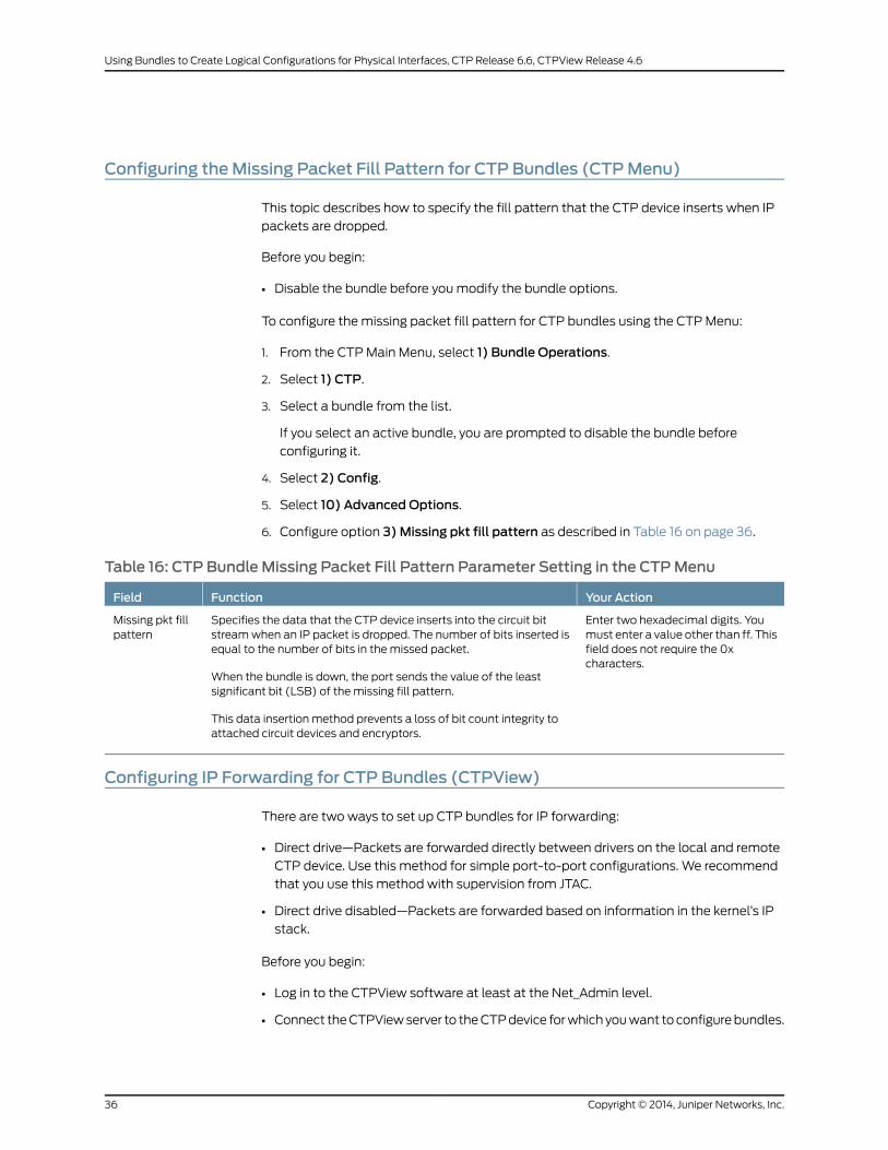
Configuring theMissing Packet Fill Pattern for CTP Bundles (CTPMenu)
This topic describes how to specify the fill pattern that the CTP device inserts when IP
packets are dropped.
Before you begin:
• Disable the bundle before youmodify the bundle options.
To configure the missing packet fill pattern for CTP bundles using the CTPMenu:
1. From the CTPMain Menu, select 1) Bundle Operations.
2. Select 1) CTP.
3. Select a bundle from the list.
If you select an active bundle, you are prompted to disable the bundle before
configuring it.
4. Select 2) Config.
5. Select 10) Advanced Options.
6. Configure option 3)Missing pkt fill pattern as described in Table 16 on page 36.
Table 16: CTP Bundle Missing Packet Fill Pattern Parameter Setting in the CTPMenu
Your ActionFunctionField
Enter two hexadecimal digits. Youmust enter a value other than ff. Thisfield does not require the 0xcharacters.
Specifies the data that the CTP device inserts into the circuit bitstreamwhen an IP packet is dropped. The number of bits inserted isequal to the number of bits in the missed packet.
When the bundle is down, the port sends the value of the leastsignificant bit (LSB) of the missing fill pattern.
This data insertion method prevents a loss of bit count integrity toattached circuit devices and encryptors.
Missing pkt fillpattern
Configuring IP Forwarding for CTP Bundles (CTPView)
There are two ways to set up CTP bundles for IP forwarding:
• Direct drive—Packets are forwarded directly between drivers on the local and remote
CTP device. Use this method for simple port-to-port configurations. We recommend
that you use this method with supervision from JTAC.
• Direct drive disabled—Packets are forwarded based on information in the kernel’s IP
stack.
Before you begin:
• Log in to the CTPView software at least at the Net_Admin level.
• Connect theCTPViewserver to theCTPdevice forwhichyouwant toconfigurebundles.
Copyright © 2014, Juniper Networks, Inc.36
Using Bundles to Create Logical Configurations for Physical Interfaces, CTP Release 6.6, CTPView Release 4.6

To configure IP forwarding for CTP bundles using CTPView:
1. In the side pane, select Bundle > Configuration.
2. Run your mouse over the Display and Select an Existing Bundle bar.
3. In the table of bundles, select the bundle that you want to modify.
4. Under Bundle Options, select Advanced Options Show to display advanced
parameters and configure the parameters as described in Table 17 on page 37.
5. Click Click to Submit Bundle AND Port Changes.
Table 17: CTP Bundle IP Forwarding Parameter Settings in CTPView
Your ActionFunctionField
Select one:
• DISABLED—CTP uses thekernel’s IP stack to forwardpackets.
• ENABLED—CTPusesdirectdriveto forward packets.
Specifies whether the CTP bundle uses direct drive or IP tables to forwardpackets.
If youare using route redundancy, portmirroring, or VLANs, youmust disabledirect drive and use IP tables.
If any port on the CTP node is configured for a PBS or bridged port, then theDirect Drive option is automatically set to Disabled on all existing and futurebundles on that node.
If a port is configured as aPBSor bridged port, then the bundles on that portis deleted. If a bundle is created on a different port, then it disables DirectDrive on that port when other ports are configured as a PBS or bridged port.
DirectDrive
Configuring IP Forwarding for CTP Bundles (CTPMenu)
There are two ways to set up CTP bundles for IP forwarding:
• Direct drive—Packets are forwarded directly between drivers on the local and remote
CTP device. Use this method for simple port-to-port configurations. We recommend
that you use this method with supervision from JTAC.
• Direct drive disabled—Packets are forwarded based on information in the kernel’s IP
stack.
Before you begin:
• Disable the bundle before youmodify the bundle options.
To configure IP forwarding for CTP bundles using the CTPMenu:
1. From the CTPMain Menu, select 1) Bundle Operations.
2. Select 1) CTP.
3. Select a bundle from the list.
If you select an active bundle, you are prompted to disable the bundle before
configuring it.
4. Select 2) Config.
37Copyright © 2014, Juniper Networks, Inc.
Chapter 2: Configuring CTP Bundles

5. Select 10) Advanced Options.
6. Configure option 13 as described in Table 18 on page 38.
Table 18: CTP Bundle IP Forwarding Settings in the CTPMenu
Your ActionFunctionField
Select one:
• YES—CTP uses the kernel’s IPstack to forward packets.
• NO—CTP uses direct drive toforward packets.
Specifies whether the CTP bundle uses direct drive or IP tables to forwardpackets.
If youareusing route redundancy, portmirroring, orVLANs, youmustdisabledirect drive and use IP tables.
If any port on the CTP node is configured for a PBSor bridged port, then theDirectDrive option is automatically set toDisabledonall existing and futurebundles on that node.
If a port is configured as a PBS or Bridged port, then the bundles on thatport is deleted. If a bundle is created on a different port, then it disablesDirectDriveon thatportwhenotherports are configuredasaPBSorbridgedport.
Disabledirect drive
Copyright © 2014, Juniper Networks, Inc.38
Using Bundles to Create Logical Configurations for Physical Interfaces, CTP Release 6.6, CTPView Release 4.6

Configuring Signaling for CTP Bundles (CTPView)
You can set input and output signals for the CTP device. Your settings should be based
on the settings of the user equipment.
• Output signals—You can set output signals to a fixed value, or you can set them to
inband so that the output signal state is based on the state of the input signal at the
user equipment.Output signals that youcanset varydependingonwhether thebundle
is configured as the DTE or the DCE:
• DTE output signals:
• DTR (data set ready)
• RTS (request to send)
• LL (local loopback)
• RL (remote loopback)
• DCE output signals:
• DSR (data set ready)
• CTS (clear to send)
• DCD (data carrier detect)
• TM (test mode)
• Input signals—Youcanset the input signals toeither unused (ignored)or used tocreate
a demand circuit. When configured for demand, packets created from the circuit are
transferred across the IP network only when the signal lead is in the specified state for
the circuit to be Demand Call – Active. When two or more leads are configured for
demand, all configured leads must be in the Demand Call – Active state for the circuit
to transfer packets across the IP network.
Input signals that you can set vary depending on whether the bundle is configured as
the DTE or the DCE:
• DTE—Input signals are TM, CTS, DSR, DCD.
• DCE—Input signals are RL, RTS, DTR, LL.
The input state of each signal lead is encoded once in every transmitted IP packet.
Thus the granularity of the transitions (frequency or changes) that can be transferred
across the network is equal to the packet rate of the circuit.
Before you begin:
• Log in to the CTPView software at least at the Net_Admin level.
• Connect theCTPViewserver to theCTPdevice forwhichyouwant toconfigurebundles.
39Copyright © 2014, Juniper Networks, Inc.
Chapter 2: Configuring CTP Bundles

To configure signaling for CTP bundles using CTPView:
1. In the side pane, select Bundle > Configuration.
2. Run your mouse over the Display and Select an Existing Bundle bar.
3. In the table of bundles, select the bundle that you want to modify.
4. Under Bundle Options, select Advanced Options Show to display advanced
parameters and configure the parameters as described in Table 19 on page 40.
5. Click Click to Submit Bundle AND Port Changes.
Table 19: CTP Bundle Signaling Settings in CTPView
Your ActionFunctionField
Select the number of packets:
• 0
• 1
• 2
• 3
Specifies the output signaling delay inpackets.
Signal Out -Output Delay
Select one:
• Fixed - Low—Signal is turned on.
• Fixed - High—Signal is turned off.
• InBand - From Remote RL—Output signal is based on the stateof the RL input signal from the DCE or the TM signal from theDTE.
• InBand -FromRemoteRTS—Output signal is basedon the stateof the RTS input signal from the DCE or the CTS signal from theDTE.
• InBand -FromRemoteDTR—Output signal is basedon thestateof the DTR input signal from the DCE or the DSR signal from theDTE.
• InBand - From Remote LL—Output signal is based on the stateof the LL input signal from the DCE or the DCD signal from theDTE.
Specifies theoutput signal dependingonwhether the bundle is configured as theDCE or the DTE:
• DCE—DSR output signal.
• DTE—DTR output signal.
Signal Out -DSR/DTR
Select one:
• Fixed - Low—Signal is turned on.
• Fixed - High—Signal is turned off.
• InBand - From Remote RL—Output signal is based on the stateof the RL input signal from the DCE or the TM signal from theDTE.
• InBand -FromRemoteRTS—Output signal is basedon the stateof the RTS input signal from the DCE or the CTS signal from theDTE.
• InBand -FromRemoteDTR—Output signal is basedon thestateof the DTR input signal from the DCE or the DSR signal from theDTE.
• InBand - From Remote LL—Output signal is based on the stateof the LL input signal from the DCE or the DCD signal from theDTE.
Specifies theoutput signal dependingonwhether the bundle is configured as theDCE or the DTE:
• DCE—CTS output signal.
• DTE—RTS output signal.
Signal Out -CTS/RTS
Copyright © 2014, Juniper Networks, Inc.40
Using Bundles to Create Logical Configurations for Physical Interfaces, CTP Release 6.6, CTPView Release 4.6

Table 19: CTP Bundle Signaling Settings in CTPView (continued)
Your ActionFunctionField
Select one:
• Fixed - Low—Signal is turned on.
• Fixed - High—Signal is turned off.
• InBand - From Remote RL—Output signal is based on the stateof the RL input signal from the DCE or the TM signal from theDTE.
• InBand -FromRemoteRTS—Output signal is basedon the stateof the RTS input signal from the DCE or the CTS signal from theDTE.
• InBand -FromRemoteDTR—Output signal is basedon thestateof the DTR input signal from the DCE or the DSR signal from theDTE.
• InBand - From Remote LL—Output signal is based on the stateof the LL input signal from the DCE or the DCD signal from theDTE.
Specifies theoutput signal dependingonwhether the bundle is configured as theDCE or the DTE:
• DCE—DCD output signal.
• DTE—LL output signal.
Signal Out -DCD/LL
Select one:
• Fixed - Low—Signal is turned on.
• Fixed - High—Signal is turned off.
• InBand - From Remote RL—Output signal is based on the stateof the RL input signal from the DCE or the TM signal from theDTE.
• InBand -FromRemoteRTS—Output signal is basedon the stateof the RTS input signal from the DCE or the CTS signal from theDTE.
• InBand -FromRemoteDTR—Output signal is basedon thestateof the DTR input signal from the DCE or the DSR signal from theDTE.
• InBand - From Remote LL—Output signal is based on the stateof the LL input signal from the DCE or the DCD signal from theDTE.
Specifies theoutput signal dependingonwhether the bundle is configured as theDCE or the DTE:
• DCE—TM output signal.
• DTE—RL output signal.
Signal Out -TM/RL
Select one:
• Unused—Input signals are ignored.
• Demand Call - Active High—Signal is turned off.
• Demand Call - Active Low—Signal is turned on.
Specifies the input signal depending onwhether the bundle is configured as theDCE or the DTE:
• DCE—RL input signal.
• DTE—TM input signal.
Signal In -RL/TM
Select one:
• Unused—Input signals are ignored.
• Demand Call - Active High—Signal is turned off.
• Demand Call - Active Low—Signal is turned on.
Specifies the input signal depending onwhether the bundle is configured as theDCE or the DTE:
• DCE—RTS input signal.
• DTE—CTS input signal.
Signal In -RTS/CTS
41Copyright © 2014, Juniper Networks, Inc.
Chapter 2: Configuring CTP Bundles
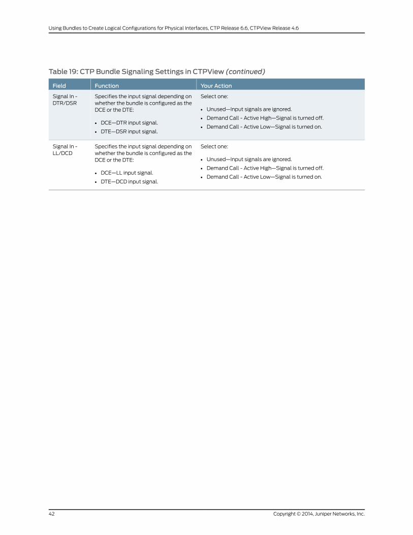
Table 19: CTP Bundle Signaling Settings in CTPView (continued)
Your ActionFunctionField
Select one:
• Unused—Input signals are ignored.
• Demand Call - Active High—Signal is turned off.
• Demand Call - Active Low—Signal is turned on.
Specifies the input signal depending onwhether the bundle is configured as theDCE or the DTE:
• DCE—DTR input signal.
• DTE—DSR input signal.
Signal In -DTR/DSR
Select one:
• Unused—Input signals are ignored.
• Demand Call - Active High—Signal is turned off.
• Demand Call - Active Low—Signal is turned on.
Specifies the input signal depending onwhether the bundle is configured as theDCE or the DTE:
• DCE—LL input signal.
• DTE—DCD input signal.
Signal In -LL/DCD
Copyright © 2014, Juniper Networks, Inc.42
Using Bundles to Create Logical Configurations for Physical Interfaces, CTP Release 6.6, CTPView Release 4.6
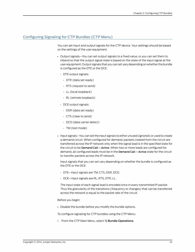
Configuring Signaling for CTP Bundles (CTPMenu)
You can set input and output signals for the CTP device. Your settings should be based
on the settings of the user equipment.
• Output signals—You can set output signals to a fixed value, or you can set them to
inband so that the output signal state is based on the state of the input signal at the
user equipment.Output signals that youcanset varydependingonwhether thebundle
is configured as the DTE or the DCE:
• DTE output signals:
• DTR (data set ready)
• RTS (request to send)
• LL (local loopback)
• RL (remote loopback)
• DCE output signals:
• DSR (data set ready)
• CTS (clear to send)
• DCD (data carrier detect)
• TM (test mode)
• Input signals—Youcanset the input signals toeither unused (ignored)or used tocreate
a demand circuit. When configured for demand, packets created from the circuit are
transferred across the IP network only when the signal lead is in the specified state for
the circuit to be Demand Call – Active. When two or more leads are configured for
demand, all configured leads must be in the Demand Call – Active state for the circuit
to transfer packets across the IP network.
Input signals that you can set vary depending on whether the bundle is configured as
the DTE or the DCE:
• DTE—Input signals are TM, CTS, DSR, DCD.
• DCE—Input signals are RL, RTS, DTR, LL.
The input state of each signal lead is encoded once in every transmitted IP packet.
Thus the granularity of the transitions (frequency or changes) that can be transferred
across the network is equal to the packet rate of the circuit.
Before you begin:
• Disable the bundle before youmodify the bundle options.
To configure signaling for CTP bundles using the CTPMenu:
1. From the CTPMain Menu, select 1) Bundle Operations.
43Copyright © 2014, Juniper Networks, Inc.
Chapter 2: Configuring CTP Bundles

2. Select 1) CTP.
3. Select a bundle from the list.
If you select an active bundle, you are prompted to disable the bundle before
configuring it.
4. Select 2) Config.
5. Select 10) Advanced Options.
6. Select 11) Signaling Config.
7. Configure the options as described in Table 20 on page 44.
Table 20: CTP Bundle Signaling Parameter Settings in the CTPMenu
Your ActionFunctionField
Select one:
• 0) Fixed
• 1) In-Band
If you chose Fixed, select:
• 0=Space=Low=On—Signal is turned on.
• 1=Mark=High=Off—Signal is turned off.
If you chose In-Band, select a remote signal source:
• 0) RL from remDCE, TM from remDTE—Output signalis based on the state of the RL input signal from theDCE or the TM signal from the DTE.
• 1)RTSfromremDCE,CTSfromremDTE—Outputsignalis based on the state of the RTS input signal from theDCE or the CTS signal from the DTE.
• 2) DTR from rem DCE, DSR from rem DTE—Outputsignal is basedon the stateof theDTR input signal fromthe DCE or the DSR signal from the DTE.
• 3) LL from remDCE,DCD from remDTE—Output signalis basedon thestateof theLL input signal fromtheDCEor the DCD signal from the DTE.
Specifies the output signal depending onwhether the bundle is configured as the DCEor the DTE:
• DCE—DSR output signal.
• DTE—DTR output signal.
DSR (output)
or
DTR (output)
Copyright © 2014, Juniper Networks, Inc.44
Using Bundles to Create Logical Configurations for Physical Interfaces, CTP Release 6.6, CTPView Release 4.6

Table 20: CTP Bundle Signaling Parameter Settings in the CTPMenu (continued)
Your ActionFunctionField
Select one:
• 0) Fixed
• 1) In-Band
If you chose Fixed, select:
• 0=Space=Low=On—Signal is turned on.
• 1=Mark=High=Off—Signal is turned off.
If you chose In-Band, select a remote signal source:
• 0) RL from remDCE, TM from remDTE—Output signalis based on the state of the RL input signal from theDCE or the TM signal from the DTE.
• 1)RTSfromremDCE,CTSfromremDTE—Outputsignalis based on the state of the RTS input signal from theDCE or the CTS signal from the DTE.
• 2) DTR from rem DCE, DSR from rem DTE—Outputsignal is basedon the stateof theDTR input signal fromthe DCE or the DSR signal from the DTE.
• 3) LL from remDCE,DCD from remDTE—Output signalis basedon thestateof theLL input signal fromtheDCEor the DCD signal from the DTE.
Specifies the output signal depending onwhether the bundle is configured as the DCEor the DTE:
• DCE—CTS output signal.
• DTE—RTS output signal.
CTS (output)
or
RTS (output)
Select one:
• 0) Fixed
• 1) In-Band
If you chose Fixed, select:
• 0=Space=Low=On—Signal is turned on.
• 1=Mark=High=Off—Signal is turned off.
If you chose In-Band, select a remote signal source:
• 0) RL from remDCE, TM from remDTE—Output signalis based on the state of the RL input signal from theDCE or the TM signal from the DTE.
• 1)RTSfromremDCE,CTSfromremDTE—Outputsignalis based on the state of the RTS input signal from theDCE or the CTS signal from the DTE.
• 2) DTR from rem DCE, DSR from rem DTE—Outputsignal is basedon the stateof theDTR input signal fromthe DCE or the DSR signal from the DTE.
• 3) LL from remDCE,DCD from remDTE—Output signalis basedon thestateof theLL input signal fromtheDCEor the DCD signal from the DTE.
Specifies the output signal depending onwhether the bundle is configured as the DCEor the DTE:
• DCE—DCD output signal.
• DTE—LL output signal.
DCD (output)
or
LL (output)
45Copyright © 2014, Juniper Networks, Inc.
Chapter 2: Configuring CTP Bundles
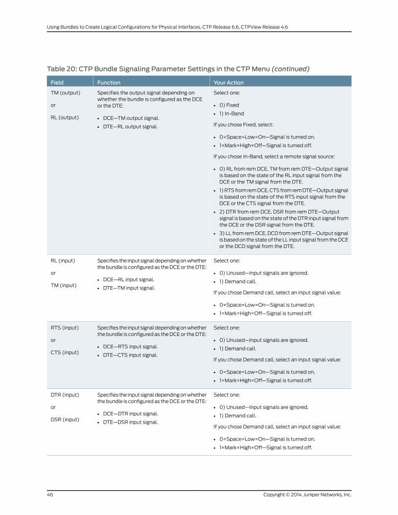
Table 20: CTP Bundle Signaling Parameter Settings in the CTPMenu (continued)
Your ActionFunctionField
Select one:
• 0) Fixed
• 1) In-Band
If you chose Fixed, select:
• 0=Space=Low=On—Signal is turned on.
• 1=Mark=High=Off—Signal is turned off.
If you chose In-Band, select a remote signal source:
• 0) RL from remDCE, TM from remDTE—Output signalis based on the state of the RL input signal from theDCE or the TM signal from the DTE.
• 1)RTSfromremDCE,CTSfromremDTE—Outputsignalis based on the state of the RTS input signal from theDCE or the CTS signal from the DTE.
• 2) DTR from rem DCE, DSR from rem DTE—Outputsignal is basedon the stateof theDTR input signal fromthe DCE or the DSR signal from the DTE.
• 3) LL from remDCE,DCD from remDTE—Output signalis basedon thestateof theLL input signal fromtheDCEor the DCD signal from the DTE.
Specifies the output signal depending onwhether the bundle is configured as the DCEor the DTE:
• DCE—TM output signal.
• DTE—RL output signal.
TM (output)
or
RL (output)
Select one:
• 0) Unused—Input signals are ignored.
• 1) Demand call.
If you chose Demand call, select an input signal value:
• 0=Space=Low=On—Signal is turned on.
• 1=Mark=High=Off—Signal is turned off.
Specifies the inputsignaldependingonwhetherthe bundle is configured as theDCEor theDTE:
• DCE—RL input signal.
• DTE—TM input signal.
RL (input)
or
TM (input)
Select one:
• 0) Unused—Input signals are ignored.
• 1) Demand call.
If you chose Demand call, select an input signal value:
• 0=Space=Low=On—Signal is turned on.
• 1=Mark=High=Off—Signal is turned off.
Specifies the inputsignaldependingonwhetherthe bundle is configured as theDCEor theDTE:
• DCE—RTS input signal.
• DTE—CTS input signal.
RTS (input)
or
CTS (input)
Select one:
• 0) Unused—Input signals are ignored.
• 1) Demand call.
If you chose Demand call, select an input signal value:
• 0=Space=Low=On—Signal is turned on.
• 1=Mark=High=Off—Signal is turned off.
Specifies the inputsignaldependingonwhetherthe bundle is configured as theDCEor theDTE:
• DCE—DTR input signal.
• DTE—DSR input signal.
DTR (input)
or
DSR (input)
Copyright © 2014, Juniper Networks, Inc.46
Using Bundles to Create Logical Configurations for Physical Interfaces, CTP Release 6.6, CTPView Release 4.6

Table 20: CTP Bundle Signaling Parameter Settings in the CTPMenu (continued)
Your ActionFunctionField
Select one:
• 0) Unused—Input signals are ignored.
• 1) Demand call.
If you chose Demand call, select an input signal value:
• 0=Space=Low=On—Signal is turned on.
• 1=Mark=High=Off—Signal is turned off.
Specifies the inputsignaldependingonwhetherthe bundle is configured as theDCEor theDTE:
• DCE—LL input signal.
• DTE—DCD input signal.
LL (input)
or
DCD (input)
Enter a number from 0 through 3.Specifies theoutput signalingdelay in packets.Output delay(pkts)
Configuring Serial Port Parameters for CTP Bundles (CTPView)
This topic describes how to configure port parameters for serial interfaces.
Before you begin:
• Log in to the CTPView software at least at the Net_Admin level.
• Connect theCTPViewserver to theCTPdevice forwhichyouwant toconfigurebundles.
To configure serial port parameters for CTP bundles using CTPView:
1. In the side pane, select Bundle > Configuration.
2. Run your mouse over the Display and Select an Existing Bundle bar.
3. In the table of bundles, select the bundle that you want to modify.
4. Under Port Options configure the parameters as described in Table 21 on page 47.
5. Click Click to Submit Bundle AND Port Changes.
Table 21: CTP Bundle Serial Port Parameter Settings in CTPView
Your ActionFunctionField
Enter a description of up to 64alphanumeric characters. Do not use thefollowing characters:
( ; ' " ) ]
Specifies a description for the port.Port Description
Select one:
• DCE—The interface is connected to aDCE device.
• DTE—The interface is connected to aDTE device.
Specifies that the interface is connectedto a data communication equipment(DCE) device or to a data terminalequipment (DTE) device.
I/F Mode
47Copyright © 2014, Juniper Networks, Inc.
Chapter 2: Configuring CTP Bundles
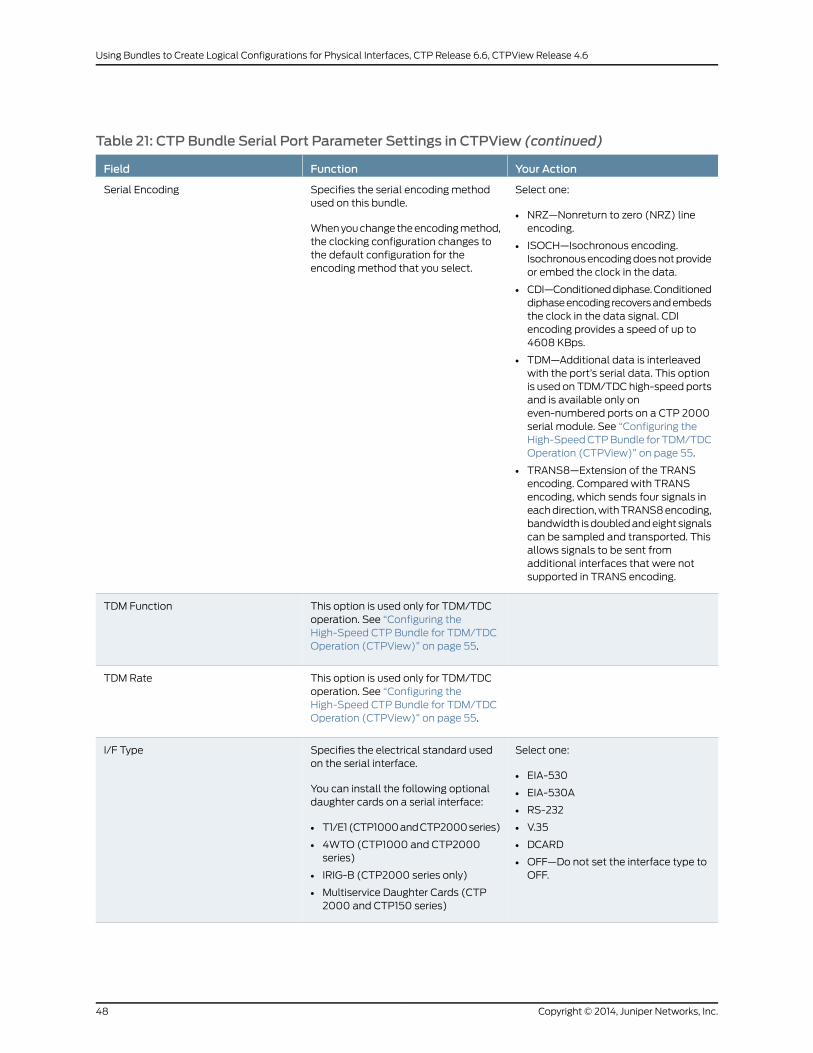
Table 21: CTP Bundle Serial Port Parameter Settings in CTPView (continued)
Your ActionFunctionField
Select one:
• NRZ—Nonreturn to zero (NRZ) lineencoding.
• ISOCH—Isochronous encoding.Isochronousencodingdoesnotprovideor embed the clock in the data.
• CDI—Conditioneddiphase.Conditioneddiphaseencoding recoversandembedsthe clock in the data signal. CDIencoding provides a speed of up to4608 KBps.
• TDM—Additional data is interleavedwith the port’s serial data. This optionis used on TDM/TDC high-speed portsand is available only oneven-numbered ports on a CTP 2000serial module. See “Configuring theHigh-SpeedCTPBundle for TDM/TDCOperation (CTPView)” on page 55.
• TRANS8—Extension of the TRANSencoding. Compared with TRANSencoding, which sends four signals ineachdirection,withTRANS8encoding,bandwidth isdoubledandeight signalscan be sampled and transported. Thisallows signals to be sent fromadditional interfaces that were notsupported in TRANS encoding.
Specifies the serial encoding methodused on this bundle.
Whenyouchange theencodingmethod,the clocking configuration changes tothe default configuration for theencoding method that you select.
Serial Encoding
This option is used only for TDM/TDCoperation. See “Configuring theHigh-Speed CTP Bundle for TDM/TDCOperation (CTPView)” on page 55.
TDM Function
This option is used only for TDM/TDCoperation. See “Configuring theHigh-Speed CTP Bundle for TDM/TDCOperation (CTPView)” on page 55.
TDM Rate
Select one:
• EIA-530
• EIA-530A
• RS-232
• V.35
• DCARD
• OFF—Do not set the interface type toOFF.
Specifies the electrical standard usedon the serial interface.
You can install the following optionaldaughter cards on a serial interface:
• T1/E1(CTP1000andCTP2000series)
• 4WTO (CTP1000 and CTP2000series)
• IRIG-B (CTP2000 series only)
• Multiservice Daughter Cards (CTP2000 and CTP150 series)
I/F Type
Copyright © 2014, Juniper Networks, Inc.48
Using Bundles to Create Logical Configurations for Physical Interfaces, CTP Release 6.6, CTPView Release 4.6

Table 21: CTP Bundle Serial Port Parameter Settings in CTPView (continued)
Your ActionFunctionField
Enter a number from 0.00100 through12880.00000 KHz.
Specifies the speed of the port. Innetworks without bandwidthconstraints, we recommend amultipleof 10.
The port speed recommendations varyaccording to encoding type:
• For transparent mode circuits, theport speed is the sample rate for userdata. Therefore, port rate should beamultiple of the user data rate.
• For CDI circuits, the port speed islimited to 4608 KBps.
The port speed also varies dependingon hardware:
• CTP2000 devices cannot have anaggregate port rate greater than114.688Mbps.
Port Speed
Configuring Serial Port Parameters for CTP Bundles (CTPMenu)
This topic describes how to configure port parameters for serial interfaces.
Before you begin:
• Disable the bundle before youmodify the bundle options.
To configure serial port parameters for CTP bundles using the CTPMenu:
1. From the CTPMain Menu, select 1) Bundle Operations.
2. Select 1) CTP.
3. Select a bundle from the list.
If you select an active bundle, you are prompted to disable the bundle before
configuring it.
4. Select 3) Port Config.
5. Configure the options as described in Table 22 on page 49.
Table 22: CTP Bundle Serial Port Parameter Settings in the CTPMenu
Your ActionFunctionField
Enter a description of up to 64alphanumeric characters. Do not usethe following characters:
( ; ' " ) ]
Specifies a description for the port.Port descriptor text
49Copyright © 2014, Juniper Networks, Inc.
Chapter 2: Configuring CTP Bundles

Table 22: CTP Bundle Serial Port Parameter Settings in the CTPMenu (continued)
Your ActionFunctionField
Select 2) Interface.Displays the menu used to configure theinterface type, mode, and encoding.
Interface
Select one:
• OFF—Donot set the interface type toOFF.
• EIA-530
• EIA-530A
• RS-232
• V.35
• Optional Interface
Specifies the electrical standard usedonthe serial interface.
You can install the following optionaldaughter cards on a serial interface:
• T1/E1 (CTP1000andCTP2000series)
• 4WTO (CTP1000 and CTP2000series)
• IRIG-B (CTP2000 series only)
• Multiservice Daughter Cards (CTP2000 and CTP150 series)
Type
Select one:
• DCE—The interface is connected toa DCE device.
• DTE—The interface is connected toa DTE device.
Specifies that the interface is connectedto a data communication equipment(DCE) device or to a data terminalequipment (DTE) device.
Mode
Copyright © 2014, Juniper Networks, Inc.50
Using Bundles to Create Logical Configurations for Physical Interfaces, CTP Release 6.6, CTPView Release 4.6
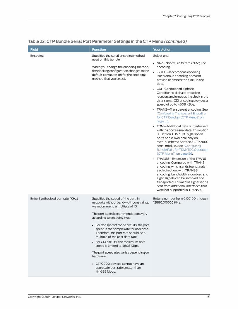
Table 22: CTP Bundle Serial Port Parameter Settings in the CTPMenu (continued)
Your ActionFunctionField
Select one:
• NRZ—Nonreturn to zero (NRZ) lineencoding.
• ISOCH—Isochronous encoding.Isochronous encoding does notprovide or embed the clock in thedata.
• CDI—Conditioned diphase.Conditioned diphase encodingrecovers andembeds the clock in thedata signal. CDI encoding provides aspeed of up to 4608 KBps.
• TRANS—Transparent encoding. See“Configuring Transparent Encodingfor CTP Bundles (CTPMenu)” onpage 53.
• TDM—Additional data is interleavedwith theport’s serial data. Thisoptionis used on TDM/TDC high-speedports and is available only oneven-numberedportsonaCTP2000serial module. See “ConfiguringBundlePairs forTDM/TDCOperation(CTPMenu)” on page 56.
• TRANS8—Extension of the TRANSencoding. Compared with TRANSencoding,which sends four signals ineach direction, with TRANS8encoding, bandwidth is doubled andeight signals can be sampled andtransported.Thisallowssignals tobesent from additional interfaces thatwere not supported in TRANS 4.
Specifies the serial encoding methodused on this bundle.
When you change the encodingmethod,theclockingconfigurationchanges to thedefault configuration for the encodingmethod that you select.
Encoding
Enter a number from 0.00100 through12880.00000 KHz.
Specifies the speed of the port. Innetworkswithoutbandwidthconstraints,we recommend amultiple of 10.
The port speed recommendations varyaccording to encoding type:
• For transparentmodecircuits, theportspeed is the sample rate for user data.Therefore, the port rate should be amultiple of the user data rate.
• For CDI circuits, the maximum portspeed is limited to 4608 KBps.
The port speed also varies depending onhardware:
• CTP2000 devices cannot have anaggregate port rate greater than114.688Mbps.
Enter Synthesized port rate (KHz)
51Copyright © 2014, Juniper Networks, Inc.
Chapter 2: Configuring CTP Bundles
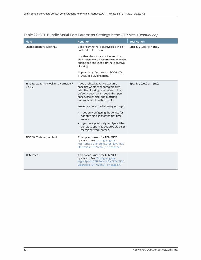
Table 22: CTP Bundle Serial Port Parameter Settings in the CTPMenu (continued)
Your ActionFunctionField
Specify y (yes) or n (no).Specifies whether adaptive clocking isenabled for this circuit.
If both end nodes are not locked to aclock reference,we recommend that youenable one end (not both) for adaptiveclocking
Appears only if you select ISOCH, CDI,TRANS, or TDM encoding.
Enable adaptive clocking?
Specify y (yes) or n (no).If you enabled adaptive clocking,specifies whether or not to initializeadaptive clocking parameters to theirdefault values, which depend on portspeed, packet size, and bufferingparameters set on the bundle.
We recommend the following settings:
• If you are configuring the bundle foradaptive clocking for the first time,enter y.
• If you have previously configured thebundle to optimize adaptive clockingfor this network, enter n.
Initialize adaptive clocking parameters?y[n]: y
This option is used for TDM/TDCoperation. See “Configuring theHigh-Speed CTP Bundle for TDM/TDCOperation (CTPMenu)” on page 57.
TDC Clk/Data on port N+1
This option is used for TDM/TDCoperation. See “Configuring theHigh-Speed CTP Bundle for TDM/TDCOperation (CTPMenu)” on page 57.
TDM rates
Copyright © 2014, Juniper Networks, Inc.52
Using Bundles to Create Logical Configurations for Physical Interfaces, CTP Release 6.6, CTPView Release 4.6

Configuring Transparent Encoding for CTP Bundles (CTPMenu)
This topic describes how to configure transparent encoding for CTP bundles. Youmust
configure transparent encoding on each end of the circuit.
To reduce transport latency, we recommend that you use the smallest buffer values
possible for networks.
NOTE: There are twomodes of transparent encoding. They are Transparent4mode (TRANS) and Transparent 8mode (TRANS8). Transparent 8modeis only supported on CTPOS release 6.4 and later. This topic describes howto configure the TRANS encoding.
Before you begin:
• Disable the bundle before youmodify the bundle options.
To configure transparent encoding using the CTPMenu:
1. From the CTPMain Menu, select 1) Bundle Operations.
2. Select 1) CTP.
3. Select a bundle from the list.
If you select an active bundle, you are prompted to disable the bundle before
configuring it.
4. Select 3) Port Config.
5. Select 2) Interface.
6. SetMode to DCE and set Encoding to TRANS.
7. Follow the onscreen instructions to configure the options as described in
Table 23 on page 53.
Table 23: Transparent Mode Parameter Settings in the CTPMenu
Your ActionFunctionField
Enter a number from0.00100 through1024.000000 KHz.
Specifies the speed of the port. For transparent mode circuits, the portspeed is the sample rate for user data. Therefore, the port rate should beamultipleof theuserdata rate. Innetworkswithoutbandwidthconstraints,we recommend amultiple of 10.
Enter Synthesized portrate (KHz)
Specify y (yes)or n (no).Specifies whether adaptive clocking is enabled for this circuit.
If both end nodes are not locked to a clock reference,we recommend thatyou enable one end (not both) for adaptive clocking
Enable adaptiveclocking?
53Copyright © 2014, Juniper Networks, Inc.
Chapter 2: Configuring CTP Bundles
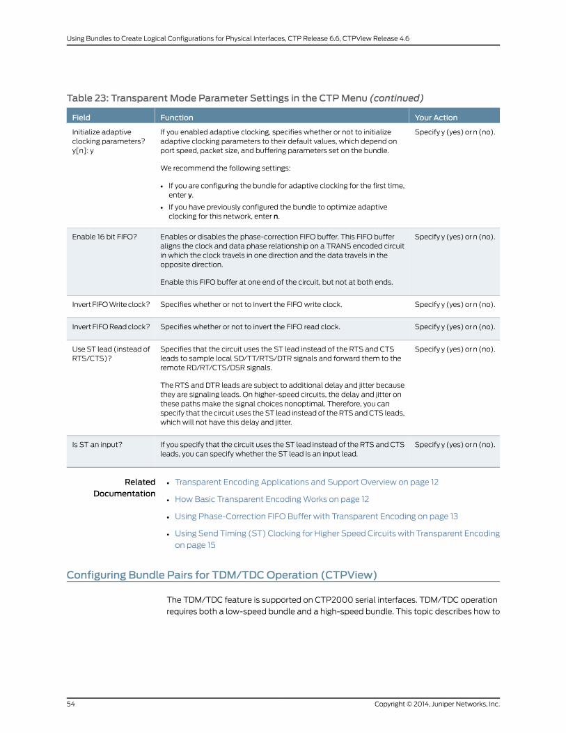
Table 23: Transparent Mode Parameter Settings in the CTPMenu (continued)
Your ActionFunctionField
Specify y (yes)or n (no).If you enabled adaptive clocking, specifies whether or not to initializeadaptive clocking parameters to their default values, which depend onport speed, packet size, and buffering parameters set on the bundle.
We recommend the following settings:
• If you are configuring the bundle for adaptive clocking for the first time,enter y.
• If you have previously configured the bundle to optimize adaptiveclocking for this network, enter n.
Initialize adaptiveclocking parameters?y[n]: y
Specify y (yes)or n (no).Enables or disables the phase-correction FIFO buffer. This FIFO bufferaligns the clock and data phase relationship on a TRANS encoded circuitin which the clock travels in one direction and the data travels in theopposite direction.
Enable this FIFO buffer at one end of the circuit, but not at both ends.
Enable 16 bit FIFO?
Specify y (yes)or n (no).Specifies whether or not to invert the FIFO write clock.Invert FIFOWriteclock?
Specify y (yes)or n (no).Specifies whether or not to invert the FIFO read clock.Invert FIFOReadclock?
Specify y (yes)or n (no).Specifies that the circuit uses the ST lead instead of the RTS and CTSleads to sample local SD/TT/RTS/DTR signals and forward them to theremote RD/RT/CTS/DSR signals.
The RTS and DTR leads are subject to additional delay and jitter becausethey are signaling leads. On higher-speed circuits, the delay and jitter onthese paths make the signal choices nonoptimal. Therefore, you canspecify that the circuit uses theST lead instead of theRTSandCTS leads,which will not have this delay and jitter.
Use ST lead (instead ofRTS/CTS)?
Specify y (yes)or n (no).If you specify that the circuit uses the ST lead instead of the RTS and CTSleads, you can specify whether the ST lead is an input lead.
Is ST an input?
RelatedDocumentation
Transparent Encoding Applications and Support Overview on page 12•
• How Basic Transparent EncodingWorks on page 12
• Using Phase-Correction FIFO Buffer with Transparent Encoding on page 13
• Using Send Timing (ST) Clocking for Higher Speed Circuits with Transparent Encoding
on page 15
Configuring Bundle Pairs for TDM/TDCOperation (CTPView)
The TDM/TDC feature is supported on CTP2000 serial interfaces. TDM/TDC operation
requires both a low-speed bundle and a high-speed bundle. This topic describes how to
Copyright © 2014, Juniper Networks, Inc.54
Using Bundles to Create Logical Configurations for Physical Interfaces, CTP Release 6.6, CTPView Release 4.6

configure the high-speed and low-speed bundle port options when used for TDM/TDC
bundles using CTPView.
1. Configuring the High-Speed CTP Bundle for TDM/TDC Operation
(CTPView) on page 55
2. Configuring theLow-SpeedCTPBundle forTDM/TDCOperation(CTPView)onpage56
Configuring the High-Speed CTP Bundle for TDM/TDCOperation (CTPView)
Configure the high-speed bundle on an even-numbered port.
Before you begin:
• Log in to the CTPView software at least at the Net_Admin level.
• Connect theCTPViewserver to theCTPdevice forwhichyouwant toconfigurebundles.
To configure a high-speed CTP bundle for TDM/TDC operation using CTPView:
1. In the side pane, select Bundle > Configuration.
2. Run your mouse over the Display and Select an Existing Bundle bar.
3. In the table of bundles, select the bundle that youwant tomodify. Youmust configure
the bundle on an even-numbered port.
4. Under Port Options, configure the parameters as described in Table 24 on page 55and click Click to Submit Bundle AND Port Changes.
5. Configure the rest of the bundle as you normally would.
Table 24: High-Speed CTP Bundle Parameters for TDM/TDCOperation in CTPView
Your ActionFunctionField
Specify TDM as the encoding method.Specifies the serial encoding method used on this bundle.SerialEncoding
Select the following:
TDC Clk/Data on port N+1—Oversamples theincoming clock (TT) and data (SD) from theadjacent port above this one (N+1) at this port’sclock rate, andembeds it in its data.At the remoteend of the network, the embedded circuit data isrecovered and exits the node on port N+1 as RTand RD outputs.
Because of the direct interleaving of two ports’data, TDC ismaintainedbetween these twoportswith anaccuracyof onebit timeat this port’s datarate.
Specifies theTDMfunction.Currently, onlyoneTDMfunctionis supported.
This option is available only on even-numbered ports on aCTP2000 serial module, and when the serial encodingparameter is set to TDM.
TDMFunction
55Copyright © 2014, Juniper Networks, Inc.
Chapter 2: Configuring CTP Bundles
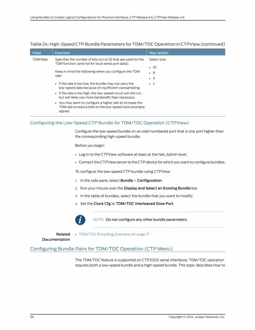
Table24:High-SpeedCTPBundleParameters forTDM/TDCOperation inCTPView (continued)
Your ActionFunctionField
Select one:
• 16
• 8
• 4
• 2
Specifies the number of bits out of 32 that are used for theTDM function (and not for local serial port data).
Keep in mind the following when you configure the TDMrate:
• If the rate is too low, the bundle may not carry thelow-speed data because of insufficient oversampling.
• If the rate is too high, the low-speed circuit will still run,but will likely use more bandwidth than necessary.
• Youmay want to configure a higher rate to increase theTDM rate to reduce jitter on the low-speed clock anddatasignals.
TDM Rate
Configuring the Low-Speed CTP Bundle for TDM/TDCOperation (CTPView)
Configure the low-speed bundle on an odd-numbered port that is one port higher than
the corresponding high-speed bundle.
Before you begin:
• Log in to the CTPView software at least at the Net_Admin level.
• Connect theCTPViewserver to theCTPdevice forwhichyouwant toconfigurebundles.
To configure the low-speed CTP bundle using CTPView:
1. In the side pane, select Bundle > Configuration.
2. Run your mouse over the Display and Select an Existing Bundle bar.
3. In the table of bundles, select the bundle that you want to modify.
4. Set the Clock Cfg to TDM/TDC Interleaved Slow Port.
NOTE: Do not configure any other bundle parameters.
RelatedDocumentation
TDM/TDC Encoding Overview on page 17•
Configuring Bundle Pairs for TDM/TDCOperation (CTPMenu)
The TDM/TDC feature is supported on CTP2000 serial interfaces. TDM/TDC operation
requires both a low-speed bundle and a high-speed bundle. This topic describes how to
Copyright © 2014, Juniper Networks, Inc.56
Using Bundles to Create Logical Configurations for Physical Interfaces, CTP Release 6.6, CTPView Release 4.6

configure the high-speed and low-speed bundle port options when used for TDM/TDC
bundles using CTPMenu.
1. Configuring the High-Speed CTP Bundle for TDM/TDC Operation (CTP
Menu) on page 57
2. Configuring the Low-Speed CTP Bundle for TDM/TDC Operation (CTP
Menu) on page 58
Configuring the High-Speed CTP Bundle for TDM/TDCOperation (CTPMenu)
Configure the high-speed bundle on an even-numbered port.
Before you begin:
• Disable the bundle before youmodify the bundle options.
To configure a high-speed CTP bundle for TDM/TDC operation using the CTPMenu:
1. From the CTPMain Menu, select 1) Bundle Operations.
2. Select 1) CTP.
3. Select a bundle from the list. Youmust configure the bundle on an even-numbered
port.
If you select an active bundle, you are prompted to disable the bundle before
configuring it.
4. Select 3) Port Config.
5. Select 2) Interface.
6. Select 3) Encoding.
7. Select 5) TDM.
8. Follow the onscreen instructions to configure the parameters as described in
Table 25 on page 57.
9. Configure the rest of the bundle as you normally would.
Table 25: High-Speed CTP Bundle Parameters for TDM/TDCOperation in the CTPMenu
Your ActionFunctionField
Press Enter.Specifies that the TDM function is TDC Clk/Data on port N+1.
This option is available only on even-numbered ports on a CTP2000 serial module, andwhen the serial encoding parameter is set to TDM.
TDC Clk/Data on port N+1 oversamples the incoming clock (TT) and data (SD) from theadjacent port above this one (N+1) at this port’s clock rate, and embeds it in its data. At theremote end of the network, the embedded circuit data is recovered and exits the node onport N+1 as RT and RD outputs.
Because of the direct interleaving of two ports’ data, TDC ismaintained between these twoports with an accuracy of one bit time at this port’s data rate.
TDC Clk/Dataon port N+1
57Copyright © 2014, Juniper Networks, Inc.
Chapter 2: Configuring CTP Bundles

Table 25: High-Speed CTP Bundle Parameters for TDM/TDCOperation in the CTPMenu (continued)
Your ActionFunctionField
Select one:
• 16
• 8
• 4
• 2
Specifies the number of bits out of 32 that are used for the TDM function (and not for localserial port data).
Appears only if you selected TDM encoding.
Keep in mind the following when you configure the TDM rate:
• If the rate is too low, the bundlemay not carry the low-speed data because of insufficientoversampling.
• If the rate is too high, the low-speed circuitwill still run, butwill likely usemore bandwidththan necessary.
• Youmay want to configure a higher rate to increase the TDM rate to reduce jitter on thelow-speed clock and data signals.
TDM rates
Configuring the Low-Speed CTP Bundle for TDM/TDCOperation (CTPMenu)
Configure the low-speed bundle on an odd-numbered port that is one higher than the
corresponding high-speed bundle.
Before you begin:
• Disable the bundle before youmodify the bundle options.
To configure the low-speed CTP bundle using CTPMenu:
1. From the CTPMain Menu, select 1) Bundle Operations.
2. Select 1) CTP.
3. Select a bundle from the list. The bundle must be configured on an even-numbered
port.
If you select an active bundle, you are prompted to disable the bundle before
configuring it.
4. Select 3) Port Config.
5. Select 3) Clock Config.
6. Select 1) Port Clock Config.
7. Select 8) TDM/TDC - Interleaved Slow Port.
NOTE: Do not configure any other bundle parameters.
RelatedDocumentation
TDM/TDC Encoding Overview on page 17•
Copyright © 2014, Juniper Networks, Inc.58
Using Bundles to Create Logical Configurations for Physical Interfaces, CTP Release 6.6, CTPView Release 4.6

Configuring T1 and E1 Port Parameters for CTP Bundles (CTPView)
This topic describes how to configure port parameters for T1/E1 interfaces.
Before you begin:
• Log in to the CTPView software at least at the Net_Admin level.
• Connect theCTPViewserver to theCTPdevice forwhichyouwant toconfigurebundles.
To configure T1 and E1 port parameters for CTP bundles using CTPView:
1. In the side pane, select Bundle > Configuration.
2. Run your mouse over the Display and Select an Existing Bundle bar.
3. In the table of bundles, select the bundle that you want to modify.
4. Under Port Options, configure the parameters as described in Table 26 on page 59.
The options vary depending on whether the bundle is T1 or E1 and whether fractional
T1 or E1 is configured.
5. Click Click to Submit Bundle AND Port Changes.
Table 26: CTP Bundle T1 and E1 Port Parameter Settings in CTPView
Your ActionFunctionField
Enter a description of up to 64alphanumeric characters. Do not use thefollowing characters:
( ; ' " ) ]
Specifies a description for the port.Port Description
Select DCARD.Specifies the daughter card as theinterface type.
I/F Type
Select one:
• T1
• E1
Specifies the type of interface.T1/E1 Choice
Select one:
• DISABLED—Card is not fractional.
• ENABLED—Card is fractional.
Specifies whether the card is fractional.Fractional
Select one:
• B8ZS
• AMI
For T1 interfaces, specifies the T1encoding method used on this bundle.
T1 Line Coding
59Copyright © 2014, Juniper Networks, Inc.
Chapter 2: Configuring CTP Bundles
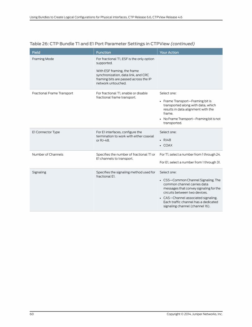
Table 26: CTP Bundle T1 and E1 Port Parameter Settings in CTPView (continued)
Your ActionFunctionField
For fractional T1, ESF is the only optionsupported.
With ESF framing, the framesynchronization, data link, and CRCframing bits are passed across the IPnetwork untouched.
Framing Mode
Select one:
• Frame Transport—Framing bit istransported along with data, whichresults in data alignment with theframe.
• NoFrameTransport—Framingbit isnottransported.
For fractional T1, enable or disablefractional frame transport.
Fractional Frame Transport
Select one:
• RJ48
• COAX
For E1 interfaces, configure thetermination to work with either coaxialor RJ-48.
E1 Connector Type
For T1, select a number from 1 through24.
For E1, select a number from 1 through 31.
Specifies the number of fractional T1 orE1 channels to transport.
Number of Channels
Select one:
• CSS—CommonChannelSignaling.Thecommon channel carries datamessages that convey signaling for thecircuits between two devices.
• CAS—Channel associated signaling.Each traffic channel has a dedicatedsignaling channel (channel 16).
Specifies the signalingmethod used forfractional E1.
Signaling
Copyright © 2014, Juniper Networks, Inc.60
Using Bundles to Create Logical Configurations for Physical Interfaces, CTP Release 6.6, CTPView Release 4.6

Table 26: CTP Bundle T1 and E1 Port Parameter Settings in CTPView (continued)
Your ActionFunctionField
Select one:
• CTP is Clock Source—The PBX eitherreturns theclock received fromtheCTPdevice, or it returns a clock that istraceable to the same source as theCTPnodeclock reference.You typicallyuse this configuration when youconfigure the CTP device with a clockreference input.
• CTP is Loop Timed—The PBX providesthe clock, and the CTP device returnsthe same clock to the PBX. Youtypically use this configuration whenthe PBX has themore accurate clocksource. You can configure the far endof the circuit with adaptive clocking torecover this clock if necessary.
• CTP is Clock Source – Adap—The PBXreturns theclock received fromtheCTPdevice, and the CTP device uses theadaptive recovered clock. You typicallyuse this configuration when the CTPdevice does not have a reference inputand the PBX typically requires a clockfrom the distant PBX.
Specifies the type of clocking for theport. The default value for Clock Cfg isCTP is Loop Timed.
Clock Cfg
Configuring T1 and E1 Port Parameters for CTP Bundles (CTPMenu)
This topic describes how to configure port parameters for T1/E1 interfaces.
Before you begin:
• Disable the bundle before youmodify the bundle options.
To configure port parameters for T1/E1 daughter cards for CTP bundles using the CTP
Menu:
1. From the CTPMain Menu, select 1) Bundle Operations.
2. Select 1) CTP.
3. Select a bundle from the list. The bundle port must have a T1/E1 daughter card
installed.
If you select an active bundle, you are prompted to disable the bundle before
configuring it.
4. Select 3) Port Config.
5. Select 2) Interface.
6. Select 1) Type and set the type toOptional Interface: T1/E1.
61Copyright © 2014, Juniper Networks, Inc.
Chapter 2: Configuring CTP Bundles

7. Follow the onscreen instructions and configure the options as described in
Table 27 on page 62.
The options vary depending on whether the bundle is T1 or E1 and whether fractional
T1 or E1 is configured.
8. To configure clocking for the port, select 3) Clock Config and configure the ClockConfig option as described in Table 27 on page 62.
Table 27: CTP Bundle T1/E1 Port Parameter Settings in the CTPMenu
Your ActionFunctionField
Enter a description of up to 64alphanumeric characters.Donotuse thefollowing characters:
( ; ' " ) ]
Specifies a description for the port.Port descriptor
Select one:
• T1
• E1
• Fractional T1
• Fractional E1
Specifies the type of interface.Type
Select one:
• B8ZS
• AMI
Specifies the T1 encoding method usedon this bundle.
Option (for T1)
Select one:
• RJ48
• COAX
For E1 interfaces, configure thetermination to work with either coaxialor RJ-48.
Option (for E1)
The following clock synthesizer settingsare set by the software, and you cannotchange them:
• For T1, the clock synthesizer is set to1544 KHz.
• For E1 the clock synthesizer is set to2048 KHz.
Clock synthesizer
For T1, select a number from 1 through24.
For E1, select a number from 1 through31.
Specifies the number of fractional T1 orE1 channels to transport.
Fractional channels
Copyright © 2014, Juniper Networks, Inc.62
Using Bundles to Create Logical Configurations for Physical Interfaces, CTP Release 6.6, CTPView Release 4.6
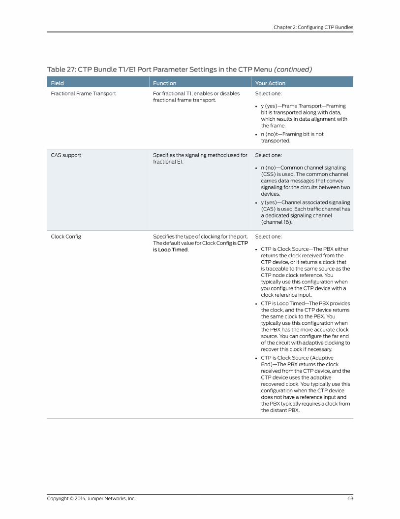
Table 27: CTP Bundle T1/E1 Port Parameter Settings in the CTPMenu (continued)
Your ActionFunctionField
Select one:
• y (yes)—Frame Transport—Framingbit is transported along with data,which results in data alignment withthe frame.
• n (no)t—Framing bit is nottransported.
For fractional T1, enables or disablesfractional frame transport.
Fractional Frame Transport
Select one:
• n (no)—Common channel signaling(CSS) is used. The common channelcarries data messages that conveysignaling for the circuits between twodevices.
• y (yes)—Channel associatedsignaling(CAS) isused. Each traffic channelhasa dedicated signaling channel(channel 16).
Specifies the signaling method used forfractional E1.
CAS support
Select one:
• CTP is Clock Source—The PBX eitherreturns the clock received from theCTP device, or it returns a clock thatis traceable to the same source as theCTP node clock reference. Youtypically use this configuration whenyou configure the CTP device with aclock reference input.
• CTP isLoopTimed—ThePBXprovidesthe clock, and the CTP device returnsthe same clock to the PBX. Youtypically use this configuration whenthe PBX has themore accurate clocksource. You can configure the far endof the circuitwith adaptive clocking torecover this clock if necessary.
• CTP is Clock Source (AdaptiveEnd)—The PBX returns the clockreceived from theCTPdevice, and theCTP device uses the adaptiverecovered clock. You typically use thisconfiguration when the CTP devicedoes not have a reference input andthePBXtypically requiresaclock fromthe distant PBX.
Specifies the typeofclocking for theport.Thedefault value forClockConfig isCTPis Loop Timed.
Clock Config
63Copyright © 2014, Juniper Networks, Inc.
Chapter 2: Configuring CTP Bundles

ConfiguringMultiservice Port Parameters for CTP Bundles (CTPView)
• Configuring Multiservice Audio Mode Port Parameters for CTP Bundles
(CTPView) on page 64
• Configuring Multiservice IRIG-B Mode Port Parameters for CTP Bundles
(CTPView) on page 65
• ConfiguringMultiserviceTDCModeParameters forCTPBundles (CTPView)onpage67
• Configuring Multiservice 4WTOMode Port Parameters for CTP Bundles
(CTPView) on page 68
ConfiguringMultiservice Audio Mode Port Parameters for CTP Bundles (CTPView)
Before you begin:
• Log in to the CTPView software at least at the Net_Admin level.
• Connect theCTPViewserver to theCTPdevice forwhichyouwant toconfigurebundles.
To configure Multiservice audio mode port parameters using CTPView:
1. In the side pane, select Bundle > Configuration.
2. Run your mouse over the Display and Select an Existing Bundle bar.
3. In the table of bundles, select the bundle that you want to modify.
4. UnderBundleOptions, configure the parameters as described in Table 28 onpage64and click Click to Submit Bundle AND Port Changes.
Table 28: CTP Bundle Multiservice Audio Port Parameter Settings in CTPView
Your ActionFunctionField
Enteradescriptionofup to64alphanumericcharacters. Do not use the followingcharacters:
( ; ' " ) ]
Specifies a description for the port.Port Description
Select DCARD.Specifies the daughter card as the interface type.I/F Type
Select Audio.Specifies that the bundle will run in audio mode.Multi-ServiceMode
Select one:
• Master—This end of the circuit providesclocking.
• Slave—This end of the circuit usesadaptive clocking.
Specifies whether this end of the circuit provides clockingor uses adaptive clocking.
If the CTP devices at both ends of the circuit aresynchronized, you can configure both ends as Master.
Audio Mode
Select one:
• Channel 0—Enables only channel 0.
• Dual Channel—Enables both channel 0and channel 1.
Specifies the channel or channels to enable.Audio Channel
Copyright © 2014, Juniper Networks, Inc.64
Using Bundles to Create Logical Configurations for Physical Interfaces, CTP Release 6.6, CTPView Release 4.6
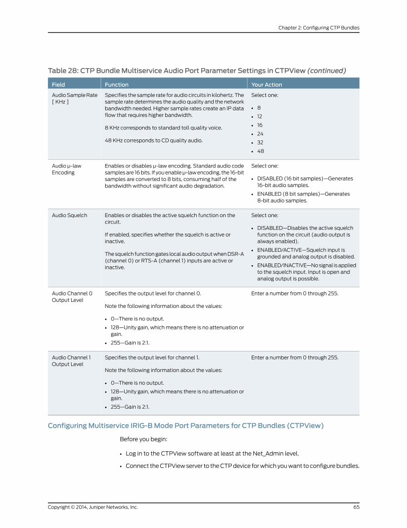
Table 28: CTP Bundle Multiservice Audio Port Parameter Settings in CTPView (continued)
Your ActionFunctionField
Select one:
• 8
• 12
• 16
• 24
• 32
• 48
Specifies the sample rate for audio circuits in kilohertz. Thesample rate determines the audio quality and the networkbandwidth needed. Higher sample rates create an IP dataflow that requires higher bandwidth.
8 KHz corresponds to standard toll quality voice.
48 KHz corresponds to CD quality audio.
AudioSampleRate[ KHz ]
Select one:
• DISABLED (16 bit samples)—Generates16-bit audio samples.
• ENABLED (8 bit samples)—Generates8-bit audio samples.
Enables or disables μ-law encoding. Standard audio codesamplesare 16bits. If youenableμ-lawencoding, the 16-bitsamples are converted to 8 bits, consuming half of thebandwidth without significant audio degradation.
Audio μ-lawEncoding
Select one:
• DISABLED—Disables the active squelchfunction on the circuit (audio output isalways enabled).
• ENABLED/ACTIVE—Squelch input isgrounded and analog output is disabled.
• ENABLED/INACTIVE—Nosignal isappliedto the squelch input. Input is open andanalog output is possible.
Enables or disables the active squelch function on thecircuit.
If enabled, specifies whether the squelch is active orinactive.
Thesquelch functiongates localaudiooutputwhenDSR-A(channel 0) or RTS-A (channel 1) inputs are active orinactive.
Audio Squelch
Enter a number from 0 through 255.Specifies the output level for channel 0.
Note the following information about the values:
• 0—There is no output.
• 128—Unity gain, whichmeans there is no attenuation orgain.
• 255—Gain is 2:1.
Audio Channel 0Output Level
Enter a number from 0 through 255.Specifies the output level for channel 1.
Note the following information about the values:
• 0—There is no output.
• 128—Unity gain, whichmeans there is no attenuation orgain.
• 255—Gain is 2:1.
Audio Channel 1Output Level
ConfiguringMultiservice IRIG-BMode Port Parameters for CTP Bundles (CTPView)
Before you begin:
• Log in to the CTPView software at least at the Net_Admin level.
• Connect theCTPViewserver to theCTPdevice forwhichyouwant toconfigurebundles.
65Copyright © 2014, Juniper Networks, Inc.
Chapter 2: Configuring CTP Bundles
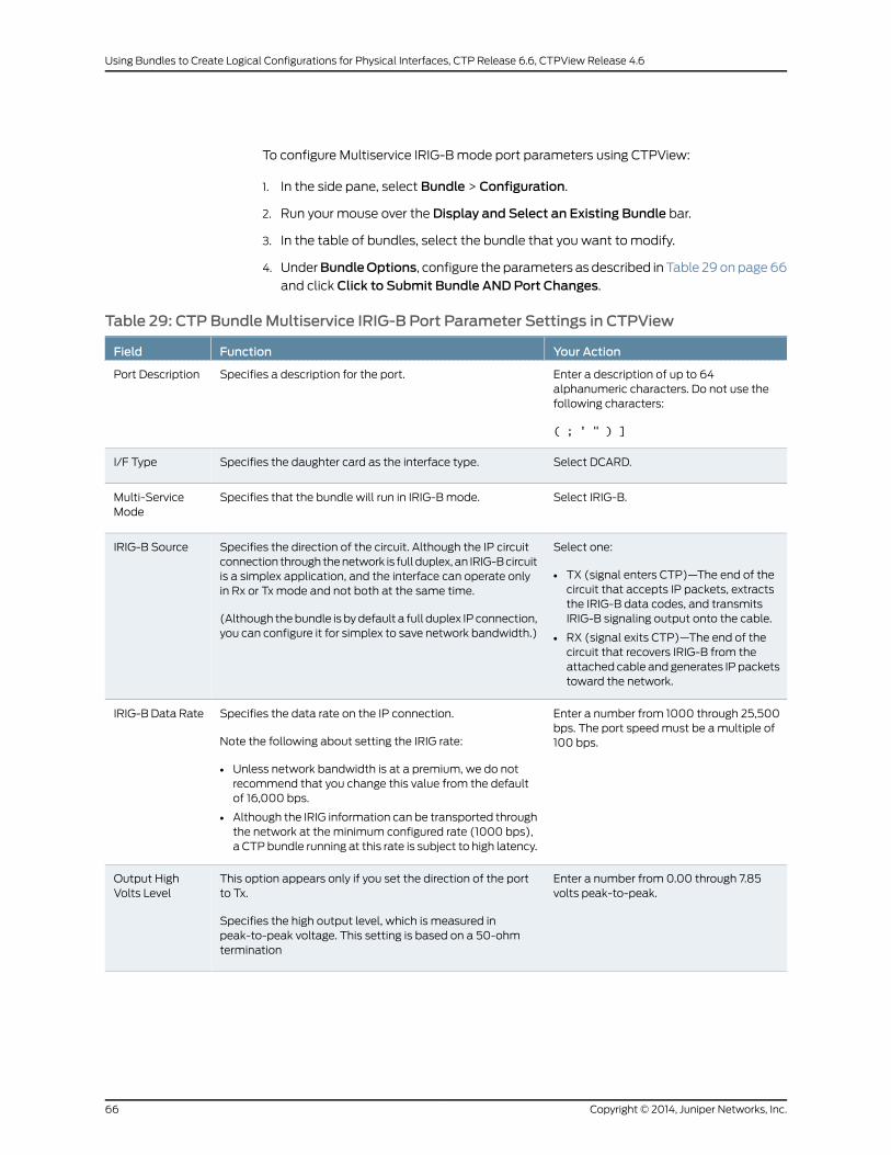
To configure Multiservice IRIG-Bmode port parameters using CTPView:
1. In the side pane, select Bundle > Configuration.
2. Run your mouse over the Display and Select an Existing Bundle bar.
3. In the table of bundles, select the bundle that you want to modify.
4. UnderBundleOptions, configure the parameters as described in Table 29onpage66and click Click to Submit Bundle AND Port Changes.
Table 29: CTP Bundle Multiservice IRIG-B Port Parameter Settings in CTPView
Your ActionFunctionField
Enter a description of up to 64alphanumeric characters. Do not use thefollowing characters:
( ; ' " ) ]
Specifies a description for the port.Port Description
Select DCARD.Specifies the daughter card as the interface type.I/F Type
Select IRIG-B.Specifies that the bundle will run in IRIG-Bmode.Multi-ServiceMode
Select one:
• TX (signal enters CTP)—The end of thecircuit that accepts IP packets, extractsthe IRIG-B data codes, and transmitsIRIG-B signaling output onto the cable.
• RX (signal exits CTP)—The end of thecircuit that recovers IRIG-B from theattached cable and generates IP packetstoward the network.
Specifies the direction of the circuit. Although the IP circuitconnection through thenetwork is full duplex, an IRIG-Bcircuitis a simplex application, and the interface can operate onlyin Rx or Tx mode and not both at the same time.
(Although thebundle is bydefault a full duplex IP connection,you can configure it for simplex to save network bandwidth.)
IRIG-B Source
Enter a number from 1000 through 25,500bps. The port speedmust be amultiple of100 bps.
Specifies the data rate on the IP connection.
Note the following about setting the IRIG rate:
• Unless network bandwidth is at a premium, we do notrecommend that you change this value from the defaultof 16,000 bps.
• Although the IRIG information can be transported throughthe network at the minimum configured rate (1000 bps),a CTP bundle running at this rate is subject to high latency.
IRIG-B Data Rate
Enter a number from 0.00 through 7.85volts peak-to-peak.
This option appears only if you set the direction of the portto Tx.
Specifies the high output level, which is measured inpeak-to-peak voltage. This setting is based on a 50-ohmtermination
Output HighVolts Level
Copyright © 2014, Juniper Networks, Inc.66
Using Bundles to Create Logical Configurations for Physical Interfaces, CTP Release 6.6, CTPView Release 4.6

Table 29: CTP Bundle Multiservice IRIG-B Port Parameter Settings in CTPView (continued)
Your ActionFunctionField
Enter a number from 0.00 through 7.85volts peak-to-peak.
This option appears only if you set the direction of the portto Tx.
Specifies the low output level, which is measured inpeak-to-peak voltage. This setting is based on a 50-ohmtermination.
Output LowVolts Level
ConfiguringMultiservice TDCMode Parameters for CTP Bundles (CTPView)
Before you begin:
• Log in to the CTPView software at least at the Net_Admin level.
• Connect theCTPViewserver to theCTPdevice forwhichyouwant toconfigurebundles.
To configure Multiservice TDCmode port parameters using CTPView:
1. In the side pane, select Bundle > Configuration.
2. Run your mouse over the Display and Select an Existing Bundle bar.
3. In the table of bundles, select the bundle that you want to modify.
4. UnderBundleOptions, configure the parameters as described in Table 30 on page 67and click Click to Submit Bundle AND Port Changes.
Table 30: CTP Bundle Multiservice TDC Port Parameter Settings in CTPView
Your ActionFunctionField
Enter a description of up to 64 alphanumericcharacters. Do not use the following characters:
( ; ' " ) ]
Specifies a description for the port.Port Description
Select DCARD.Specifies thedaughter cardas the interface type.I/F Type
Select TDC.Specifies that the bundle will run in TDCmode.Multi-Service Mode
Select one:
• Source (signal enters CTP)—End of the circuitthat receives NRZ/IRIG data.
• Destination (signal exitsCTP)—Endof thecircuitthat sends NRZ/IRIG data toward the network.
Specifies the direction of the circuit.TDC Source
Enter a number from 500 through 5,000,000 bpsin multiples of 500.
Specifies theNRZdata rateon the IPconnection.TDC NRZ Rate
67Copyright © 2014, Juniper Networks, Inc.
Chapter 2: Configuring CTP Bundles

Table 30: CTP Bundle Multiservice TDC Port Parameter Settings in CTPView (continued)
Your ActionFunctionField
Enter a number from 0 through 255.Specifies the output level.
Note the following informationabout the values:
• 0—There is no output.
• 128—Unity gain, which means there is noattenuation or gain.
• 255—Gain is 2:1.
TDC IRIGOutputLevel
ConfiguringMultiservice 4WTOMode Port Parameters for CTP Bundles (CTPView)
Before you begin:
• Log in to the CTPView software at least at the Net_Admin level.
• Connect theCTPViewserver to theCTPdevice forwhichyouwant toconfigurebundles.
To configure Multiservice 4WTOmode port parameters using CTPView:
1. In the side pane, select Bundle > Configuration.
2. Run your mouse over the Display and Select an Existing Bundle bar.
3. In the table of bundles, select the bundle that you want to modify.
4. UnderBundleOptions, configure the parameters as described in Table 31 on page68.
5. Click Click to Submit Bundle AND Port Changes.
Table 31: CTP Bundle Multiservice 4WTOMode Port Parameter Settings in CTPView
Your ActionFunctionField
Enter a description of up to 64alphanumeric characters.Donotuse thefollowing characters:
( ; ' " ) ]
Specifies a description for the port.Port Description
Select DCARD.Specifies the daughter card as theinterface type.
I/F Type
Select 4WTOSpecifies that the bundle will run in4WTOmode.
Multi-Service Mode
Select one:
• Master—This end of the circuitprovides clocking.
• Slave—This end of the circuit usesadaptive clocking.
Specifies whether this end of the circuitprovides clocking or uses adaptiveclocking.
If the CTP devices at both ends of thecircuit are synchronized, you canconfigure both ends as Master.
4WTOMode
Copyright © 2014, Juniper Networks, Inc.68
Using Bundles to Create Logical Configurations for Physical Interfaces, CTP Release 6.6, CTPView Release 4.6
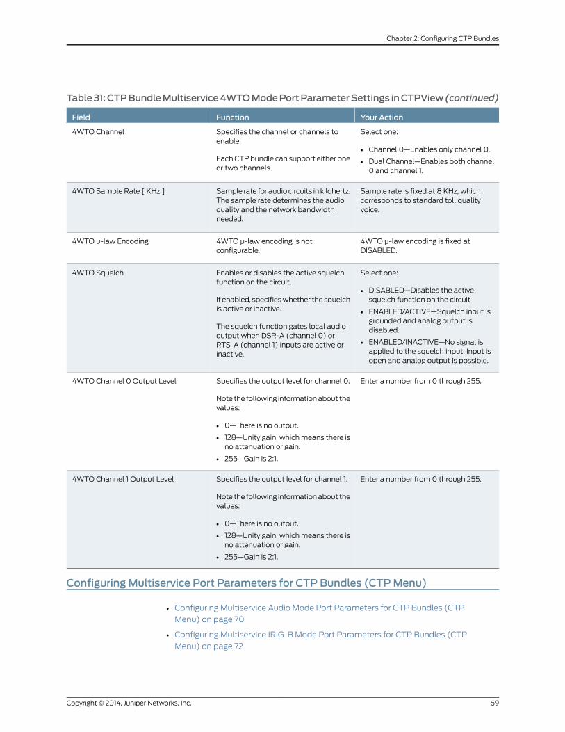
Table31:CTPBundleMultiservice4WTOModePortParameterSettings inCTPView (continued)
Your ActionFunctionField
Select one:
• Channel 0—Enables only channel 0.
• Dual Channel—Enables both channel0 and channel 1.
Specifies the channel or channels toenable.
EachCTPbundle can support either oneor two channels.
4WTO Channel
Sample rate is fixed at 8 KHz, whichcorresponds to standard toll qualityvoice.
Sample rate for audio circuits in kilohertz.The sample rate determines the audioquality and the network bandwidthneeded.
4WTO Sample Rate [ KHz ]
4WTO μ-law encoding is fixed atDISABLED.
4WTO μ-law encoding is notconfigurable.
4WTO μ-law Encoding
Select one:
• DISABLED—Disables the activesquelch function on the circuit
• ENABLED/ACTIVE—Squelch input isgrounded and analog output isdisabled.
• ENABLED/INACTIVE—No signal isapplied to the squelch input. Input isopen and analog output is possible.
Enables or disables the active squelchfunction on the circuit.
If enabled, specifieswhether the squelchis active or inactive.
The squelch function gates local audiooutput when DSR-A (channel 0) orRTS-A (channel 1) inputs are active orinactive.
4WTO Squelch
Enter a number from 0 through 255.Specifies the output level for channel 0.
Note the following informationabout thevalues:
• 0—There is no output.
• 128—Unity gain, whichmeans there isno attenuation or gain.
• 255—Gain is 2:1.
4WTO Channel 0 Output Level
Enter a number from 0 through 255.Specifies the output level for channel 1.
Note the following informationabout thevalues:
• 0—There is no output.
• 128—Unity gain, whichmeans there isno attenuation or gain.
• 255—Gain is 2:1.
4WTO Channel 1 Output Level
ConfiguringMultiservice Port Parameters for CTP Bundles (CTPMenu)
• Configuring Multiservice Audio Mode Port Parameters for CTP Bundles (CTP
Menu) on page 70
• Configuring Multiservice IRIG-B Mode Port Parameters for CTP Bundles (CTP
Menu) on page 72
69Copyright © 2014, Juniper Networks, Inc.
Chapter 2: Configuring CTP Bundles
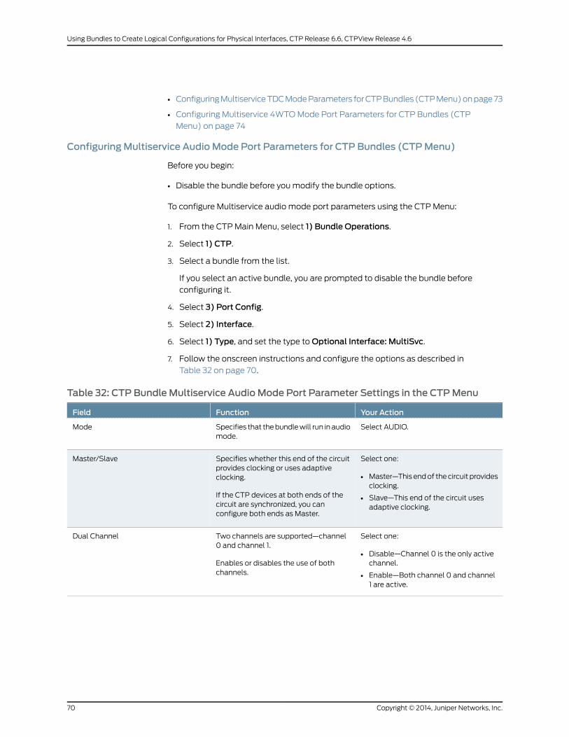
• ConfiguringMultiserviceTDCModeParameters forCTPBundles (CTPMenu)onpage73
• Configuring Multiservice 4WTOMode Port Parameters for CTP Bundles (CTP
Menu) on page 74
ConfiguringMultiservice Audio Mode Port Parameters for CTP Bundles (CTPMenu)
Before you begin:
• Disable the bundle before youmodify the bundle options.
To configure Multiservice audio mode port parameters using the CTPMenu:
1. From the CTPMain Menu, select 1) Bundle Operations.
2. Select 1) CTP.
3. Select a bundle from the list.
If you select an active bundle, you are prompted to disable the bundle before
configuring it.
4. Select 3) Port Config.
5. Select 2) Interface.
6. Select 1) Type, and set the type toOptional Interface: MultiSvc.
7. Follow the onscreen instructions and configure the options as described in
Table 32 on page 70.
Table 32: CTP Bundle Multiservice Audio Mode Port Parameter Settings in the CTPMenu
Your ActionFunctionField
Select AUDIO.Specifies that thebundlewill run inaudiomode.
Mode
Select one:
• Master—This endof thecircuit providesclocking.
• Slave—This end of the circuit usesadaptive clocking.
Specifies whether this end of the circuitprovides clocking or uses adaptiveclocking.
If the CTP devices at both ends of thecircuit are synchronized, you canconfigure both ends as Master.
Master/Slave
Select one:
• Disable—Channel 0 is the only activechannel.
• Enable—Both channel 0 and channel1 are active.
Two channels are supported—channel0 and channel 1.
Enables or disables the use of bothchannels.
Dual Channel
Copyright © 2014, Juniper Networks, Inc.70
Using Bundles to Create Logical Configurations for Physical Interfaces, CTP Release 6.6, CTPView Release 4.6

Table 32: CTP Bundle Multiservice Audio Mode Port Parameter Settings in the CTPMenu (continued)
Your ActionFunctionField
Select one:
• 8
• 12
• 16
• 24
• 32
• 48
Specifies the sample rate for audiocircuits in kilohertz. The sample ratedetermines the audio quality and thenetwork bandwidth needed. Highersample rates create an IP data flow thatrequires higher bandwidth.
8 KHz corresponds to standard tollquality voice.
48KHz corresponds toCDquality audio.
Audio Sample Rate
Select one:
• Disable—Generates 16-bit audiosamples.
• Enable—Generates 8-bit audiosamples.
Enables or disables μ-law encoding.Standardaudiocodesamplesare 16bits.If you enable μ-law encoding, the 16-bitsamples are converted to 8 bits,consuming half of the bandwidthwithout significant audio degradation.
μ-law Encoding:
Select one:
• Disable—Disables the active squelchfunction on the circuit (audio output isalways enabled).
• Enable and active—Squelch input isgrounded and analog output isdisabled.
• Enable and inactive—No signal isapplied to the squelch input. Input isopen and analog output is possible.
Enables or disables the active squelchfunction on the circuit.
If enabled, specifieswhether the squelchis active or inactive.
The squelch function gates local audiooutput when DSR-A (channel 0) orRTS-A (channel 1) inputs are active orinactive.
Talk Squelch
Enter a number from 0 through 255.Specifies the output level for channel 0.
Note the following informationabout thevalues:
• 0—There is no output.
• 128—Unity gain, whichmeans there isno attenuation or gain.
• 255—Gain is 2:1.
Ch 0 Output Level: 1.00x (decimal 128)
Enter a number from 0 through 255.Specifies the output level for channel 1.
Note the following informationabout thevalues:
• 0—There is no output.
• 128—Unity gain, whichmeans there isno attenuation or gain.
• 255—Gain is 2:1.
Ch 1 Output Level: 1.00x (decimal 128)
71Copyright © 2014, Juniper Networks, Inc.
Chapter 2: Configuring CTP Bundles

ConfiguringMultiservice IRIG-BMode Port Parameters for CTP Bundles (CTPMenu)
Before you begin:
• Disable the bundle before youmodify the bundle options.
To configure Multiservice IRIG-Bmode port parameters using the CTPMenu:
1. From the CTPMain Menu, select 1) Bundle Operations.
2. Select 1) CTP.
3. Select a bundle from the list.
If you select an active bundle, you are prompted to disable the bundle before
configuring it.
4. Select 3) Port Config.
5. Select 2) Interface.
6. Select 1) Type and set the type toOptional Interface: MultiSvc.
7. Follow the onscreen instructions and configure the options as described in
Table 33 on page 72.
Table 33: CTP Bundle Multiservice IRIG-B Port Parameter Settings in the CTPMenu
Your ActionFunctionField
Select IRIG.Specifies that the bundle will run inIRIG-Bmode.
Mode
Specify yes or no to the question: Is thisan IRIG-B source end (IRIG-B signalenters CTP)?
• Yes (y)—Sets direction to Rx. This endof the circuit recovers IRIG-B from theattached cable and generates IPpackets toward the network.
• No (n)—Sets the direction to Tx. Thisend of the circuit accepts IP packets,extracts the IRIG-B data codes, andtransmits IRIG-Bsignalingoutputontothe cable.
Specifies the direction of the circuit.Although the IP circuit connectionthrough the network is full duplex, anIRIG-B circuit is a simplex application,and the interface can operate only in Rxor Tx mode and not both at the sametime.
(Although the bundle is by default a fullduplex IP connection, you can configureit for simplex to save networkbandwidth.)
Src/Dest
Copyright © 2014, Juniper Networks, Inc.72
Using Bundles to Create Logical Configurations for Physical Interfaces, CTP Release 6.6, CTPView Release 4.6

Table33:CTPBundleMultiservice IRIG-BPortParameterSettings in theCTPMenu (continued)
Your ActionFunctionField
Enter a number from 1000 through25,500 bps. The port speedmust be amultiple of 100 bps.
Specifies the data rate on the IPconnection.
Note the followingabout setting the IRIGrate:
• Unless network bandwidth is at apremium, we do not recommend thatyouchange this value fromthedefaultof 16,000 bps.
• Although the IRIG information can betransported through the network atthe minimum configured rate (1000bps), aCTPbundle runningat this rateis subject to high latency.
IRIG Rate
Enter a number from 0.00 through 7.85volts peak-to-peak.
This setting applies only if you set thedirection of the port to Tx.
Specifies the high output level, which ismeasured in peak-to-peak voltage. Thissetting is based on a 50-ohmtermination.
Output High Level
Enter a number from 0.00 through 7.85volts peak-to-peak.
This setting applies only if you set thedirection of the port to Tx.
Specifies the low output level, which ismeasured in peak-to-peak voltage. Thissetting is based on a 50-ohmtermination.
Output Low Level
ConfiguringMultiservice TDCMode Parameters for CTP Bundles (CTPMenu)
Before you begin:
• Disable the bundle before youmodify the bundle options.
To configure Multiservice TDCmode port parameters using the CTPMenu:
1. From the CTPMain Menu, select 1) Bundle Operations.
2. Select 1) CTP.
3. Select a bundle from the list.
If you select an active bundle, you are prompted to disable the bundle before
configuring it.
4. Select 3) Port Config.
5. Select 2) Interface.
73Copyright © 2014, Juniper Networks, Inc.
Chapter 2: Configuring CTP Bundles
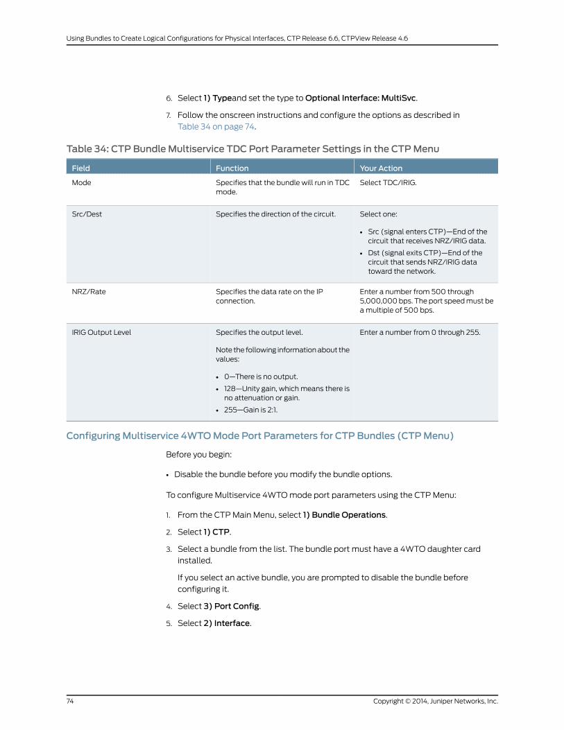
6. Select 1) Typeand set the type toOptional Interface: MultiSvc.
7. Follow the onscreen instructions and configure the options as described in
Table 34 on page 74.
Table 34: CTP Bundle Multiservice TDC Port Parameter Settings in the CTPMenu
Your ActionFunctionField
Select TDC/IRIG.Specifies that the bundle will run in TDCmode.
Mode
Select one:
• Src (signal enters CTP)—End of thecircuit that receives NRZ/IRIG data.
• Dst (signal exits CTP)—End of thecircuit that sends NRZ/IRIG datatoward the network.
Specifies the direction of the circuit.Src/Dest
Enter a number from 500 through5,000,000bps. The port speedmust beamultiple of 500 bps.
Specifies the data rate on the IPconnection.
NRZ/Rate
Enter a number from 0 through 255.Specifies the output level.
Note the following informationabout thevalues:
• 0—There is no output.
• 128—Unity gain, whichmeans there isno attenuation or gain.
• 255—Gain is 2:1.
IRIG Output Level
ConfiguringMultiservice 4WTOMode Port Parameters for CTP Bundles (CTPMenu)
Before you begin:
• Disable the bundle before youmodify the bundle options.
To configure Multiservice 4WTOmode port parameters using the CTPMenu:
1. From the CTPMain Menu, select 1) Bundle Operations.
2. Select 1) CTP.
3. Select a bundle from the list. The bundle port must have a 4WTO daughter card
installed.
If you select an active bundle, you are prompted to disable the bundle before
configuring it.
4. Select 3) Port Config.
5. Select 2) Interface.
Copyright © 2014, Juniper Networks, Inc.74
Using Bundles to Create Logical Configurations for Physical Interfaces, CTP Release 6.6, CTPView Release 4.6
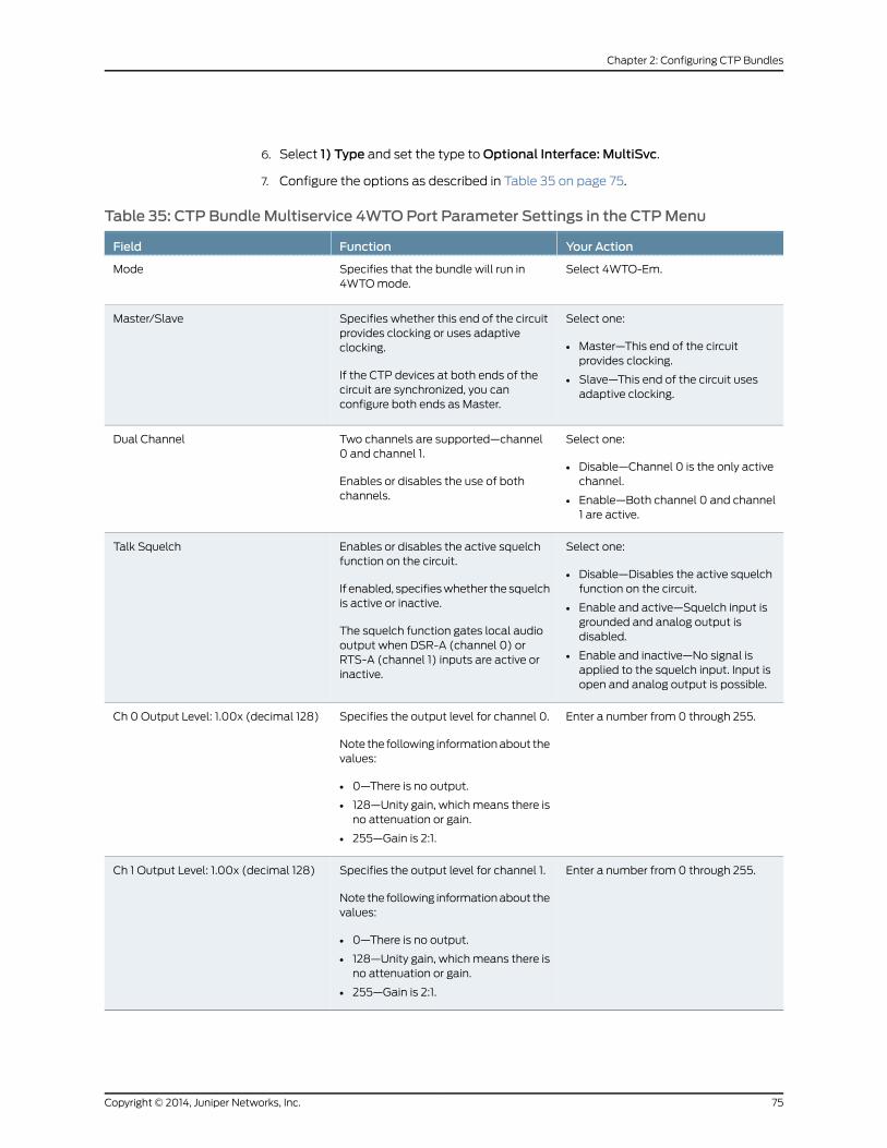
6. Select 1) Type and set the type toOptional Interface: MultiSvc.
7. Configure the options as described in Table 35 on page 75.
Table 35: CTP Bundle Multiservice 4WTOPort Parameter Settings in the CTPMenu
Your ActionFunctionField
Select 4WTO-Em.Specifies that the bundle will run in4WTOmode.
Mode
Select one:
• Master—This end of the circuitprovides clocking.
• Slave—This end of the circuit usesadaptive clocking.
Specifies whether this end of the circuitprovides clocking or uses adaptiveclocking.
If the CTP devices at both ends of thecircuit are synchronized, you canconfigure both ends as Master.
Master/Slave
Select one:
• Disable—Channel 0 is the only activechannel.
• Enable—Both channel 0 and channel1 are active.
Two channels are supported—channel0 and channel 1.
Enables or disables the use of bothchannels.
Dual Channel
Select one:
• Disable—Disables the active squelchfunction on the circuit.
• Enable and active—Squelch input isgrounded and analog output isdisabled.
• Enable and inactive—No signal isapplied to the squelch input. Input isopen and analog output is possible.
Enables or disables the active squelchfunction on the circuit.
If enabled, specifieswhether the squelchis active or inactive.
The squelch function gates local audiooutput when DSR-A (channel 0) orRTS-A (channel 1) inputs are active orinactive.
Talk Squelch
Enter a number from 0 through 255.Specifies the output level for channel 0.
Note the following informationabout thevalues:
• 0—There is no output.
• 128—Unity gain, whichmeans there isno attenuation or gain.
• 255—Gain is 2:1.
Ch 0 Output Level: 1.00x (decimal 128)
Enter a number from 0 through 255.Specifies the output level for channel 1.
Note the following informationabout thevalues:
• 0—There is no output.
• 128—Unity gain, whichmeans there isno attenuation or gain.
• 255—Gain is 2:1.
Ch 1 Output Level: 1.00x (decimal 128)
75Copyright © 2014, Juniper Networks, Inc.
Chapter 2: Configuring CTP Bundles

Configuring 4WTOPort Parameters for CTP Bundles (CTPView)
For CTP bundles, you can configure a 4WTOdaughter card installed on a serial interface
module.
Youcansetup4WTOdaughter cards to interoperatewithMultiservice Interfacemodules.
Interoperability of Multiservice Interface modules with 4WTO daughter cards requires
the following:
• Firmware revision 4 or later on the 4WTO daughter card.
• CTPView releases 3.4R4 or 4.x.
• CTPOS release 6.0 or later.
• Channel 1 cannot be configured as the channel option.
Before you begin:
• Log in to the CTPView software at least at the Net_Admin level.
• Connect theCTPViewserver to theCTPdevice forwhichyouwant toconfigurebundles.
To configure port parameters for 4WTOdaughter cards for CTP bundles using CTPView:
1. In the side pane, select Bundle > Configuration.
2. Run your mouse over the Display and Select an Existing Bundle bar.
3. In the table of bundles, select the bundle that you want to modify.
4. Under Port Options, configure the parameters as described in Table 36 on page 76.
5. Click Click to Submit Bundle AND Port Changes.
Table 36: CTP Bundle 4WTOPort Parameter Settings in CTPView
Your ActionFunctionField
Enter a description of up to 64alphanumeric characters.Donotuse thefollowing characters:
( ; ' " ) ]
Specifies a description for the port.Port Description
Select DCE.Specifies that the interface is connectedto a data communication equipment(DCE) device.
I/F Mode
Select DCARD.Specifies the daughter card as theinterface type.
I/F Type
Copyright © 2014, Juniper Networks, Inc.76
Using Bundles to Create Logical Configurations for Physical Interfaces, CTP Release 6.6, CTPView Release 4.6
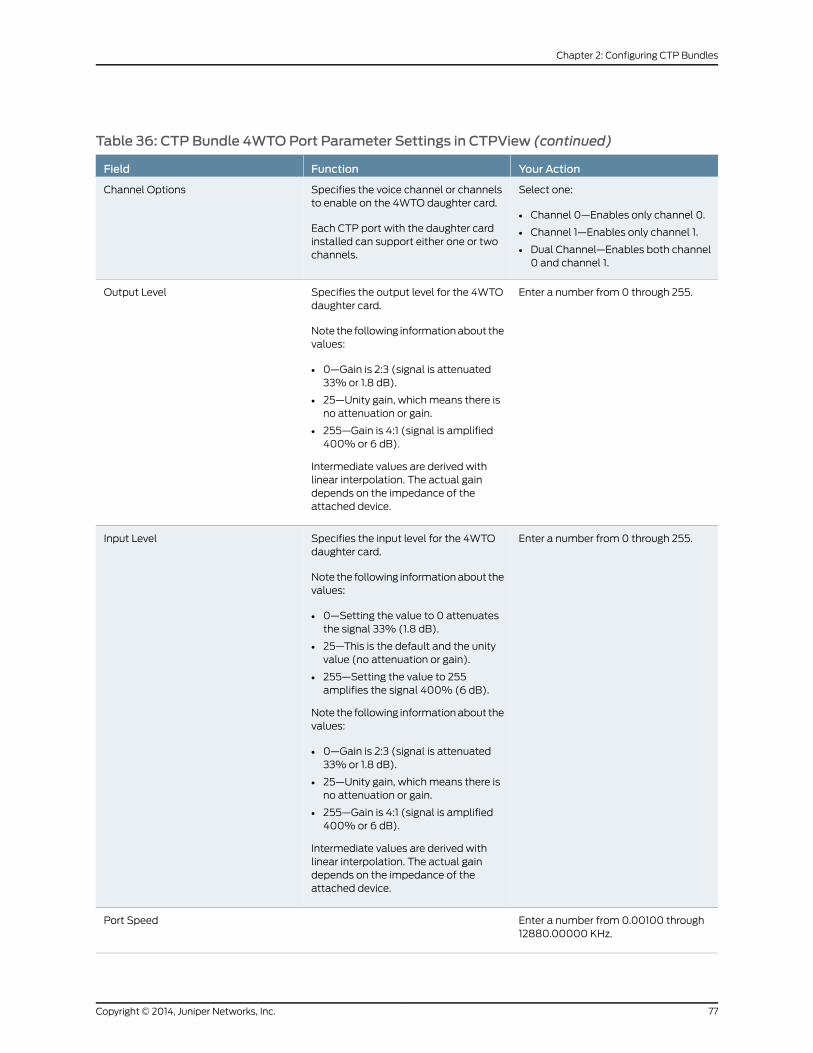
Table 36: CTP Bundle 4WTOPort Parameter Settings in CTPView (continued)
Your ActionFunctionField
Select one:
• Channel 0—Enables only channel 0.
• Channel 1—Enables only channel 1.
• Dual Channel—Enables both channel0 and channel 1.
Specifies the voice channel or channelsto enable on the 4WTO daughter card.
Each CTP port with the daughter cardinstalled can support either one or twochannels.
Channel Options
Enter a number from 0 through 255.Specifies the output level for the 4WTOdaughter card.
Note the following informationabout thevalues:
• 0—Gain is 2:3 (signal is attenuated33% or 1.8 dB).
• 25—Unity gain, which means there isno attenuation or gain.
• 255—Gain is 4:1 (signal is amplified400% or 6 dB).
Intermediate values are derived withlinear interpolation. The actual gaindepends on the impedance of theattached device.
Output Level
Enter a number from 0 through 255.Specifies the input level for the 4WTOdaughter card.
Note the following informationabout thevalues:
• 0—Setting the value to 0 attenuatesthe signal 33% (1.8 dB).
• 25—This is the default and the unityvalue (no attenuation or gain).
• 255—Setting the value to 255amplifies the signal 400% (6 dB).
Note the following informationabout thevalues:
• 0—Gain is 2:3 (signal is attenuated33% or 1.8 dB).
• 25—Unity gain, which means there isno attenuation or gain.
• 255—Gain is 4:1 (signal is amplified400% or 6 dB).
Intermediate values are derived withlinear interpolation. The actual gaindepends on the impedance of theattached device.
Input Level
Enter a number from 0.00100 through12880.00000 KHz.
Port Speed
77Copyright © 2014, Juniper Networks, Inc.
Chapter 2: Configuring CTP Bundles

Table 36: CTP Bundle 4WTOPort Parameter Settings in CTPView (continued)
Your ActionFunctionField
Select one:
• DISABLED—Disables the activesquelch function on the circuit
• ENABLED/ACTIVE—Squelch input isgrounded and analog output isdisabled.
• ENABLED/INACTIVE—No signal isapplied to the squelch input. Input isopen and analog output is possible.
Enables or disables the active squelchfunction on the circuit.
If enabled, specifieswhether the squelchis active or inactive.
The squelch function gates local audiooutput when DSR-A (channel 1) orRTS-A (channel 0) inputs are active orinactive.
Talk Squelch
• ENABLED—Interoperability with theMultiservice Interface module isenabled.
• DISABLED—Interoperability with theMultiservice Interface module isdisabled.
Enables or disables interoperability ofthe 4WTO daughter card withMultiservice Interface modules.
When you enable interoperability of the4WTO daughter card with MultiserviceInterfacemodules, theport speed for thebundle is set as follows:
• 64 when only channel 0 is enabled.
• 128 when dual channel is enabled.
MS Interwork
Select one:
• Custom—Custom clockingconfiguration is used.
• Voice/IRIG-BMaster End—This end ofthecircuit generatesaclock signal andsends it to the remote end.
• Voice/IRIG-B Slave End—This end ofthe circuit receives the clock signalfrom the remote end. The clock slaveuses its period to determine when tosampledataandhowto transmitdataacross the link.
Specifies the typeofclocking for theport.
To prevent voice channels fromgenerating occasional noise burstscaused by unsynchronized nodes, werecommend that you configure one endof the voice port (not both) for adaptiveclocking or lock both ends to clockreferences.
Clock Cfg
RelatedDocumentation
Configuring Multiservice 4WTOMode Port Parameters for CTP Bundles (CTPView)
on page 68
•
Copyright © 2014, Juniper Networks, Inc.78
Using Bundles to Create Logical Configurations for Physical Interfaces, CTP Release 6.6, CTPView Release 4.6

Configuring 4WTOPort Parameters for CTP Bundles (CTPMenu)
For CTP bundles, you can configure a 4WTOdaughter card installed on a serial interface
module.
You do not need to configure port speed and clocking for the analog 4WTO interface.
Selecting this interfacecauses theport speedandclocking tobeautomatically configured.
Youcansetup4WTOdaughter cards to interoperatewithMultiservice Interfacemodules.
Interoperability of Multiservice Interface modules with 4WTO daughter cards requires
the following:
• Firmware revision 4 or later on the 4WTO daughter card.
• CTPView releases 3.4R4 or later or releases 4.x or later.
• CTPOS release 6.0 or later.
• Channel 1 cannot be the enabled channel.
Before you begin:
• Disable the bundle before youmodify the bundle options.
To configure port parameters for 4WTO daughter cards for CTP bundles using the CTP
Menu:
1. From the CTPMain Menu, select 1) Bundle Operations.
2. Select 1) CTP.
3. Select a bundle from the list. The bundle port must have a 4WTO daughter card
installed.
If you select an active bundle, you are prompted to disable the bundle before
configuring it.
4. Select 3) Port Config.
5. Select 2) Interface.
6. Select 1) Type and set the type toOptional Interface: Voice 4W/TO.
7. Follow the onscreen instructions.
To prevent voice channels from generating occasional noise bursts caused by
unsynchronized nodes, we recommend that you either enable adaptive clocking on
one end of the voice port (not both) or lock both ends of the voice port to clock
references.
8. Configure the options as described in Table 37 on page 80.
79Copyright © 2014, Juniper Networks, Inc.
Chapter 2: Configuring CTP Bundles
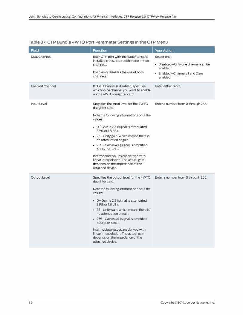
Table 37: CTP Bundle 4WTOPort Parameter Settings in the CTPMenu
Your ActionFunctionField
Select one:
• Disabled—Only one channel can beenabled.
• Enabled—Channels 1 and 2 areenabled.
Each CTP port with the daughter cardinstalled can support either one or twochannels.
Enables or disables the use of bothchannels.
Dual Channel
Enter either 0 or 1.If Dual Channel is disabled, specifieswhich voice channel you want to enableon the 4WTO daughter card.
Enabled Channel
Enter a number from 0 through 255.Specifies the input level for the 4WTOdaughter card.
Note the following informationabout thevalues:
• 0—Gain is 2:3 (signal is attenuated33% or 1.8 dB).
• 25—Unity gain, which means there isno attenuation or gain.
• 255—Gain is 4:1 (signal is amplified400% or 6 dB).
Intermediate values are derived withlinear interpolation. The actual gaindepends on the impedance of theattached device.
Input Level
Enter a number from 0 through 255.Specifies the output level for the 4WTOdaughter card.
Note the following informationabout thevalues:
• 0—Gain is 2:3 (signal is attenuated33% or 1.8 dB).
• 25—Unity gain, which means there isno attenuation or gain.
• 255—Gain is 4:1 (signal is amplified400% or 6 dB).
Intermediate values are derived withlinear interpolation. The actual gaindepends on the impedance of theattached device.
Output Level
Copyright © 2014, Juniper Networks, Inc.80
Using Bundles to Create Logical Configurations for Physical Interfaces, CTP Release 6.6, CTPView Release 4.6

Table 37: CTP Bundle 4WTOPort Parameter Settings in the CTPMenu (continued)
Your ActionFunctionField
Select one:
• DISABLED—Disables the activesquelch function on the circuit
• ENABLED/ACTIVE—Squelch input isgrounded and analog output isdisabled.
• ENABLED/INACTIVE—No signal isapplied to the squelch input. Input isopen and analog output is possible.
Enables or disables the active squelchfunction on the circuit.
If enabled, specifieswhether the squelchis active or inactive.
The squelch function gates local audiooutput when DSR-A (channel 1) orRTS-A (channel 0) inputs are active orinactive.
Talk Squelch
• Enabled—Interoperability with theMultiservice Interface module isenabled.
• Disabled—Interoperability with theMultiservice Interface module isdisabled.
Enables or disables interoperability ofthe 4WTO daughter card withMultiservice Interface modules.
When you enable interoperability of the4WTO daughter card with MultiserviceInterfacemodules, theport speed for thebundle is set as follows:
• 64 when only channel 0 is enabled.
• 128 when dual channel is enabled.
Ms interwork
Select one:
• 4WTO/IRIG -Master End—This endofthecircuit generatesaclock signal andsends it to the remote end.
• 4WTO/IRIG - Adaptive End—This endof the circuit receives the clock signalfrom the remote end. The clock slaveuses its period to determine when tosampledataandhowto transmitdataacross the link.
• Custom—The custom clockingconfiguration is used.
Specifies the typeofclocking for theport.
To prevent voice channels fromgenerating occasional noise burstscaused by unsynchronized nodes, werecommend that you configure one endof the voice port (not both) for adaptiveclocking or lock both ends to clockreferences.
Clock Config
RelatedDocumentation
Configuring Multiservice 4WTOMode Port Parameters for CTP Bundles (CTPMenu)
on page 74
•
Configuring IRIG-B Port Parameters for CTP Bundles (CTPView)
This topic describes how to configure port parameters for IRIG-B daughter cards.
Adaptive clocking is configured by default on IRIG-B bundles, and the packet size is set
to 64 bytes. The packet size combined with the default data rate of 16 Kbps produces a
packet rate of 32 pps, which is a good packet rate for adaptive clocking.
Before you begin:
• Log in to the CTPView software at least at the Net_Admin level.
81Copyright © 2014, Juniper Networks, Inc.
Chapter 2: Configuring CTP Bundles

• Connect theCTPViewserver to theCTPdevice forwhichyouwant toconfigurebundles.
To configure IRIG-B port parameters using CTPView:
1. In the side pane, select Bundle > Configuration.
2. Run your mouse over the Display and Select an Existing Bundle bar.
3. In the table of bundles, select the bundle that you want to modify.
4. UnderBundleOptions, configure the parameters as described in Table 38 on page82and click Click to Submit Bundle AND Port Changes.
Table 38: CTP Bundle IRIG-B Port Parameter Settings in CTPView
Your ActionFunctionField
Enter a description of up to 64 alphanumericcharacters. Do not use the following characters:
( ; ' " ) ]
Specifies a description for the port.PortDescription
Select DCARD.Specifies the daughter card as the interface type.I/F Type
Enter a number from 1.000 through 25.500 KHz. Theport speedmust be amultiple of 100 bps.
Specifies the data rate on the IP connection.
Unless network bandwidth is at a premium, we donot recommend that you change this value from thedefault of 16,000 bps.
Port Speed
Select one:
• RX—Theendof thecircuit that recovers IRIG-B fromtheattachedcableandgenerates IPpackets towardthe network.
• TX—The end of the circuit that accepts IP packets,extracts the IRIG-Bdatacodes,andtransmits IRIG-Bsignaling output onto the cable.
Specifies the direction of the circuit. Although the IPcircuit connection through thenetwork is full duplex,an IRIG-B circuit is actually a simplex application,and the daughter card can operate only in Rx or Txmode and not both at the same time.
Direction
Enter a number from 0.00 through 7.85 voltspeak-to-peak.
This option appears only if you set the direction ofthe port to Tx.
Specifies the high output level, which is measuredin peak-to-peak voltage. This setting is based on a50-ohm termination
Output HighVolts Level
Enter a number from 0.00 through 7.85 voltspeak-to-peak.
This option appears only if you set the direction ofthe port to Tx.
Specifies the low output level, which is measured inpeak-to-peak voltage. This setting is based on a50-ohm termination.
Output LowVolts Level
Copyright © 2014, Juniper Networks, Inc.82
Using Bundles to Create Logical Configurations for Physical Interfaces, CTP Release 6.6, CTPView Release 4.6
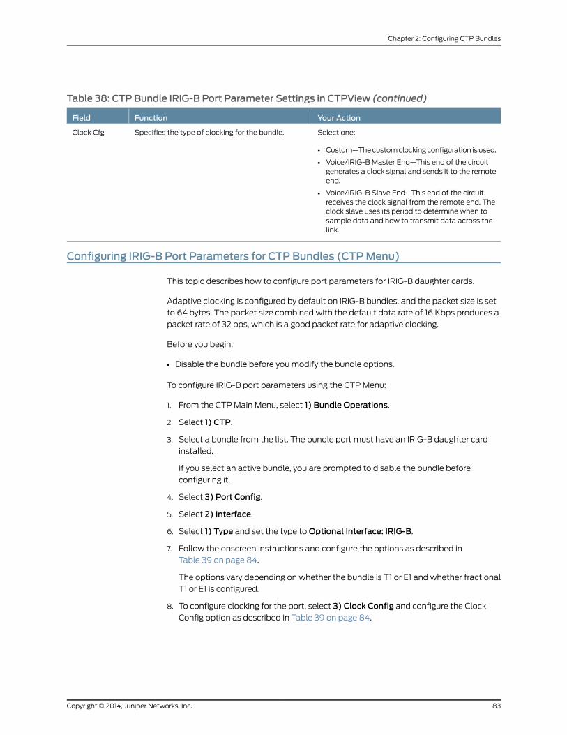
Table 38: CTP Bundle IRIG-B Port Parameter Settings in CTPView (continued)
Your ActionFunctionField
Select one:
• Custom—Thecustomclockingconfiguration isused.
• Voice/IRIG-B Master End—This end of the circuitgenerates a clock signal and sends it to the remoteend.
• Voice/IRIG-B Slave End—This end of the circuitreceives the clock signal from the remote end. Theclock slave uses its period to determine when tosample data and how to transmit data across thelink.
Specifies the type of clocking for the bundle.Clock Cfg
Configuring IRIG-B Port Parameters for CTP Bundles (CTPMenu)
This topic describes how to configure port parameters for IRIG-B daughter cards.
Adaptive clocking is configured by default on IRIG-B bundles, and the packet size is set
to 64 bytes. The packet size combined with the default data rate of 16 Kbps produces a
packet rate of 32 pps, which is a good packet rate for adaptive clocking.
Before you begin:
• Disable the bundle before youmodify the bundle options.
To configure IRIG-B port parameters using the CTPMenu:
1. From the CTPMain Menu, select 1) Bundle Operations.
2. Select 1) CTP.
3. Select a bundle from the list. The bundle port must have an IRIG-B daughter card
installed.
If you select an active bundle, you are prompted to disable the bundle before
configuring it.
4. Select 3) Port Config.
5. Select 2) Interface.
6. Select 1) Type and set the type toOptional Interface: IRIG-B.
7. Follow the onscreen instructions and configure the options as described in
Table 39 on page 84.
The options vary depending on whether the bundle is T1 or E1 and whether fractional
T1 or E1 is configured.
8. To configure clocking for the port, select 3) Clock Config and configure the ClockConfig option as described in Table 39 on page 84.
83Copyright © 2014, Juniper Networks, Inc.
Chapter 2: Configuring CTP Bundles

Table 39: CTP Bundle IRIG-B Port Parameter Settings in the CTPMenu
Your ActionFunctionField
Specify yes or no to the question: Is thisan IRIG-B source end (IRIB-B signalenters CTP)?
• Yes (y)—Sets direction toRx. This endof the circuit recovers IRIG-B from theattached cable and generates IPpackets toward the network
• No (n)—Sets the direction to Tx. Thisend of the circuit accepts IP packets,extracts the IRIG-B data codes, andtransmits IRIG-Bsignalingoutputontothe cable.
Specifies the direction of the circuit.Although the IP circuit connectionthrough the network is full duplex, anIRIG-B circuit is actually a simplexapplication, and the daughter card canoperate only in Rx or Tx mode and notboth at the same time.
Direction
Enter a number from 0.00 through 7.85volts peak-to-peak.
This setting appears only if you set thedirection of the port to Tx.
Specifies the high output level, which ismeasured in peak-to-peak voltage. Thissetting isbasedona50-ohmtermination
Output High Level
Enter a number from 0.00 through 7.85volts peak-to-peak.
This setting appears only if you set thedirection of the port to Tx.
Specifies the low output level, which ismeasured in peak-to-peak voltage. Thissetting is based on a 50-ohmtermination.
Output Low Volts Level
Enter a number from 1000 through25,500 bps. The port speedmust be amultiple of 100 bps.
Specifies the data rate on the IPconnection.
Unless network bandwidth is at apremium,wedonot recommendthatyouchange this value from the default of 16Kbps.
Port Speed (kbps)
Select one:
• 4WTO/IRIG - Master End—This endof the circuit generates a clock signaland sends it to the remote end.
• 4WTO/IRIG - Adaptive End—This endof the circuit receives the clock signalfrom the remote end. The clock slaveuses its period to determine when tosampledataandhowto transmitdataacross the link.
• Custom—The custom clockingconfiguration is used.
Specifies the type of clocking for thebundle.
Clock Config
Copyright © 2014, Juniper Networks, Inc.84
Using Bundles to Create Logical Configurations for Physical Interfaces, CTP Release 6.6, CTPView Release 4.6

Configuring Advanced Port Options for CTP Bundles (CTPView)
Before you begin:
• Log in to the CTPView software at least at the Net_Admin level.
• Connect theCTPViewserver to theCTPdevice forwhichyouwant toconfigurebundles.
To configure advanced port options for CTP bundles using CTPView:
1. In the side pane, select Bundle > Configuration.
2. Run your mouse over the Display and Select an Existing Bundle bar.
3. In the table of bundles, select the bundle that you want to modify.
4. Under Port Options, select the Advanced Options Show to display advanced
parameters and configure the parameters as described in Table 40 on page 85.
5. Click Click to Submit Bundle AND Port Changes.
Table 40: CTP Bundle Advanced Port Options Settings in CTPView
Your ActionFunctionField
Select ENABLED orDISABLED.
Do not change this value without consulting JTAC.
Specifies whether or not the CTP device drives received data (RD)onto data set ready (DSR) and real-time (RT) data onto test mode(TM).
Single Ended Data/ClockOutput
Select ENABLED orDISABLED.
Do not change this value without consulting JTAC.
Specifies whether or not to reclock RDwith the RT clock to align thedata and the clock.
Reclock to Align Clockand Data
Select ENABLED orDISABLED.
Specifies that the CTP device disqualifies transmit timing (TT) onlywhen it is higher than the port speed.
When enabled, this setting keeps the port from going to the TtFailstate when the incoming user clock fluctuates between 0 and theconfigured port rate. If the TT rate goes above the configured portrate, the CTP device sends the port to the TtFail state to protect thesystem from an overspeed TT, which would cause problems for theport, CTP device, or network.
Only High TT Checking
Select ENABLED orDISABLED.
When request to send (RTS) is inactive, specifieswhether or not theCTP device feeds TT with the internally created clock.
TT Clock Gated by RTS
Select ENABLED orDISABLED.
When clock gating is enabled, specifies whether or not to use theinverted RTS signal.
RTS Clock Gated Invert
Select ENABLED orDISABLED.
Specifies whether or not to invert data bound for the interface withdata bound for the IP network.
Input/Output DataInversion
Select ENABLED orDISABLED.
Helpsmaintain the low-speed port on a TDM/TDCCTP serial circuitat up when the high-speed circuit goes down.
Substitute DDSwhen TTgone
85Copyright © 2014, Juniper Networks, Inc.
Chapter 2: Configuring CTP Bundles

Configuring Advanced Port Options for CTP Bundles (CTPMenu)
Before you begin:
• Disable the bundle before youmodify the bundle options.
To configure advanced port options for CTP bundles using the CTPMenu:
1. From the CTPMain Menu, select 1) Bundle Operations.
2. Select 1) CTP.
3. Select a bundle from the list.
If you select an active bundle, you are prompted to disable the bundle before
configuring it.
4. Select 3) Port Config.
5. Select 4) Advanced Options.
6. Configure the options as described in Table 41 on page 86.
Table 41: CTP Bundle Advanced Port Option Settings in the CTPMenu
Your ActionFunctionField
Select y or n.Do not change this value withoutconsulting JTAC.
Specifies whether or not the CTP devicedrives received data (RD) onto data setready (DSR) and real-time (RT) dataonto test mode (TM).
Single ended data/clock outputs
Select y or n.Do not change this value withoutconsulting JTAC.
Specifies whether or not to reclock RDwith the RT clock to align the data andthe clock.
Reclock RD to align RD/RT
Select y or n.Specifies that theCTPdevicedisqualifiestransmit timing(TT)onlywhen it ishigherthan the port speed.
Whenenabled, this settingkeeps theportfrom going to the TtFail state when theincoming user clock fluctuates between0 and the configured port rate. If the TTrate goes above the configured port rate,the CTP device sends the port to theTtFail state to protect the system froman overspeed TT, which would causeproblems for the port, CTP device, ornetwork.
Only high TT checking
Copyright © 2014, Juniper Networks, Inc.86
Using Bundles to Create Logical Configurations for Physical Interfaces, CTP Release 6.6, CTPView Release 4.6

Table 41: CTP Bundle Advanced Port Option Settings in the CTPMenu (continued)
Your ActionFunctionField
Select y or n.When request to send (RTS) is inactive,specifies whether or not the CTP devicefeeds TT with the internally createdclock.
TT Clock Gated by RTS
Select y or n.When clock gating is enabled, specifieswhether or not to use the inverted RTSsignal.
RTS Clock Gate Invert
Select y or n.Specifies whether or not to invert databound for the interface with data boundfor the IP network.
Input/Output Data Invert
Select y or n.Helps maintain the low-speed port on aTDM/TDC CTP serial circuit at up whenthe high-speed circuit goes down.
Substitute DDSwhen TT gone
Configuring Port Mirroring for CTP Bundles (CTPView)
Portmirroring enables you tomirror traffic to a third port. The packet generated from the
source is sent to an assigned destination and to another port whether it is on the local
node or remote node.
Bundles that use port mirroring must have the direct drive disabled. When a bundle
configuration that has a port mirroring component is submitted, the CTPView software
enforces the direct drive rule when the node is configured to the new settings.
NOTE: To view and configure port mirroring parameters, youmust login asan administrator.
You can configure source and destination port mirroring for a CTP device fromCTPView.
To configure source and destination port mirroring for CTP bundles from CTPView:
1. In the side pane, select Bundle > Configuration.
2. Run your mouse over the Display and Select an Existing Bundle bar.
3. In the table of bundles, select the bundle that you want to configure.
4. UnderBundleOptions, selectAdvancedOptionsShowandconfigure theparameters
as described in Table 42 on page 88.
87Copyright © 2014, Juniper Networks, Inc.
Chapter 2: Configuring CTP Bundles

Table 42: Unidirectional and Bidirectional Circuit Options
DescriptionField
Select one:
• Bi-directional—Select to configure both source ad destination port mirroring.
• Source—Select to configure only source port mirroring.
• Destination—Select to configure only destination port mirroring.
Unidirectional Circuit
5. UnderBundleOptions, selectSource PortMirroring Show and theDestination PortMirroring Show and configure the parameters as described in Table 43 on page 88.
Table 43: CTP Bundle Source Port Mirroring Settings in CTPView
Your ActionField
Enter the remote IP address.Remote IP [ IPv4 only ]
Click to select the remote IP address from the list.
Select theRemoveTailcheckbox to remove theportmirroring tail fromthebundle.The check box will be visible only if port mirroring is configured.
Remote Address [ IPv4 only ]
Enter the remote circuit ID in the range 0-249.Remote CID [ 0 -249 ]
6. Click Click to Submit Bundle AND Port Changes.
RelatedDocumentation
Configuring Port Mirroring for CTP Bundles (CTPMenu) on page 88•
Configuring Port Mirroring for CTP Bundles (CTPMenu)
Portmirroring enables you tomirror traffic to a third port. The packet generated from the
source is sent to an assigned destination and to another port whether it is on the local
node or remote node.
Bundles using port mirroring must have the direct drive disabled. When a bundle
configuration that has a port mirroring component is submitted, the CTPView software
enforces the direct drive rule when the node is configured to the new settings.
NOTE: To view and configure port mirroring parameters, youmust login asan administrator.
You can configure source and destination port mirroring for a CTP device fromCTPView.
To configure source and destination port mirroring for CTP bundles from the CTPMenu:
1. From the Main Menu, select 1) Bundle Operations > 1) CTP.
2. Select a bundle from the list.
Copyright © 2014, Juniper Networks, Inc.88
Using Bundles to Create Logical Configurations for Physical Interfaces, CTP Release 6.6, CTPView Release 4.6

3. Select 2) Config> 11) Advanced Options> 10) Unidirectional circuit and configurethe parameters as described in Table 44 on page 89.
Table 44: Unidirectional and Bidirectional Circuit Options
DescriptionField
Select one:
• Bidirectional circuit—Select to configure both source ad destination port mirroring.
• Unidirectional circuit source—Select to configure only source port mirroring.
• Unidirectional circuit destination—Select to configure only destination port mirroring.
Unidirectional Circuit
4. Select 12) Port mirror Config.
Current port mirror configuration: NoneOptions(0-quit, 1-add, 2-delete, 3-show): (0-3)[3]: 1
5. Enter 1 to configure port mirroring.
6. Follow the onscreen instructions and configure the parameters as described in
Table 45 on page 89.
Table 45: CTP Bundle Source Port Mirroring Settings in CTPMenu
Your ActionField
Select one:
• yes
• no
Add Source mirroring
Enter the remote IP address.Enter remote ip address
Enter the remote circuit ID in the range 0-249.Enter remote cid
Select one:
• yes
• no
Add Destination mirroring
Enter the remote IP address for the destination port.Enter remote ip address
Enter the remote circuit ID in the range 0-249.Enter remote cid
7. From the Operations Menu, select 4) Activate to activate the bundle.
RelatedDocumentation
Configuring Port Mirroring for CTP Bundles (CTPView) on page 87•
89Copyright © 2014, Juniper Networks, Inc.
Chapter 2: Configuring CTP Bundles

Configuring Cryptographic Resynchronization (Crypto Resync)
You can use the CTP chassiswith cryptographic devices. You can configure synchronized
(in-sync) and pulse cryptographic resynchronized (resync) options for use with these
devices.
If an error occurs on a secure link, the cryptographic devices can get out of sync. When
the CTP software detects that a cryptographic device is out of sync or that keepalives
orLMIhasbeen lost, it signals to thecryptographicdevice to resyncbypulsingDSRand/or
CTS.
The NRZ port has a configuration parameter for cryptographic resynchronization where
you need to specify a port that is on the same node and is monitored. The port has to be
a Fractional T1/E1 port that has Frame transport Enabled.When the bundle that includes
these ports is up and running, the cryptographic resynchronization functionmonitors the
frame synchronization bit of the framer in the east bound direction, and if the framer
indicates loss of frame, then the cryptographic function is activated.
Youcanconfigurehow long theCTPsoftwarewaitsbefore requestinga resynchronization,
set the pulse width, and set the pulse period of the resynchronization request. You can
also configure the direction of the pulse (0 to 1 or 1 to 0). To disable the pulse, set the
in-sync and pulse value to the same value.
To configure cryptographic resynchronization:
1. From the CTPMain Menu, select 1) Bundle Operations >
2. Select 1) CTP.
3. Select a bundle from the list.
4. Select 3) Port Config > 4) Advanced Options > 11) Remote Port T1E1 crypto
This option allows this port to output a crypto resyncpulse based on the T1/E1 frame status (i/f bound) of another port.The port must be a T1/E1 port or Serial port with T1E1 DCARD.The port must be configured for fractional T1/E1 w/ frame transportThe port must be on this node.
Would you like to enable this feature? y[n]:Enter T1/E1 Port [se-0/0]:
5. Enter y and select a T1E1 port when prompted..
6. 12) Crypto Options
0) Back to Previous Menu 1) Crypto resync wait time: 4 sec 2) Crypto resync pulse width: 1 sec 3) Crypto resync pulse period: 8 sec 4) Crypto resync DSR in-sync value: 1 (mark/high/off) 5) Crypto resync DSR pulse value: 0 (space/low/on) 6) Crypto resync CTS in-sync value: 1 (mark/high/off) 7) Crypto resync CTS pulse value: 0 (space/low/on)
7. Configure the cryptographic resynchronization options as described in
Table 46 on page 91
Copyright © 2014, Juniper Networks, Inc.90
Using Bundles to Create Logical Configurations for Physical Interfaces, CTP Release 6.6, CTPView Release 4.6

Table 46: Cryptographic Resynchronization Options
Field DescriptionField Name
Number of seconds to wait between loss of sync on the port and the firstresynchronization pulse.
Enter a value in the range 1 – 60. The default value is 4 seconds
Crypto resync wait time
Pulse width in seconds. This is the number of seconds the resynchronization pulse willbe asserted.
Enter a value in the range 1 -15. the default value is 1 second
Crypto resync pulse width
Number of seconds between the beginning of each pulse. This value minus the pulsewidthequals the timebetween theendofonepulseand thebeginningof thenextpulse.
Enter a value in the range 1-1000. The default value is 8 seconds.
Crypto resync pulse period
State of DSR or DTR when the port is in sync.
Enter a value in the range 0-1. The default value is 1.
Crypto resync DSR in-sync value
State of DSR or DTR to be sent between the resynchronization pulses when the port isout of sync.
Enter a value in the range 0-1. The default value is 0.
Crypto resync DSR pulse value
State of CTS or RTS when the port is in sync.
Enter a value in the range 0-1. The default value is 1.
Crypto resync CTS in-sync value
State for CTS or RTS to be sent between the resynchronization pulses when the portis out of sync.
Enter a value in the range 0-1. The default value is 0.
Crypto resync CTS pulse value
Selecting the Type of Clocking on Serial Ports for CTP Bundles (CTPView)
This topic describes how to select the type of clocking that you want to use on serial
ports. The type of clocking supported depends on the type of encoding you are using.
Before you begin:
• Log in to the CTPView software at least at the Net_Admin level.
• Connect theCTPViewserver to theCTPdevice forwhichyouwant toconfigurebundles.
To specify the clocking type for CTP bundles using CTPView:
1. In the side pane, select Bundle > Configuration.
2. Run your mouse over the Display and Select an Existing Bundle bar.
3. In the table of bundles, select the bundle that you want to modify.
91Copyright © 2014, Juniper Networks, Inc.
Chapter 2: Configuring CTP Bundles
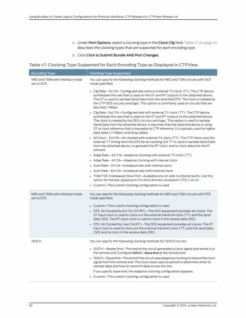
4. Under Port Options, select a clocking type in theClock Cfg field. Table 47 on page 92describes the clocking types that are supported for each encoding type.
5. Click Click to Submit Bundle AND Port Changes.
Table 47: Clocking Type Supported for Each Encoding Type as Displayed in CTPView
Clocking Type SupportedEncoding Type
You can specify the following clocking methods for NRZ and TDM circuits with DCEmode specified:
• Cfg Rate - Int Clk—Configured rate without external TX clock (TT). The CTP devicesynthesizes the rate that is used on the ST and RT outputs to the attached device.The ST is used to sample Send Data from the attached DTE. The clock is created bythe CTP DDS circuitry and logic. This option is commonly used on circuits that areless than 1 Mbps.
• Cfg Rate - Ext Clk—Configured rate with external TX clock (TT). The CTP devicesynthesizes the rate that is used on the ST and RT outputs to the attached device.The clock is created by the DDS circuitry and logic. This option is used to sampleSend Data from the attached device. It assumes that the attached device is usingST or clock reference that is traceable to CTP reference. It is typically used for higherdata rates (>1 Mbps) and long cables.
• All Clock - Ext Clk—All clocked with external TX clock (TT). The CTP clock uses theexternal TT timing from the DTE for all clocking. Ext TT is used to sample Send Datafrom the attached device, to generate the RT clock, and to clock data into the IPnetwork.
• Adap Rate - Ext Clk—Adaptive clocking with external TX clock (TT).
• Adap Rate - Int Clk—Adaptive clocking with internal clock.
• Auto Rate - Int Clk—Autobaud rate with internal clock.
• Auto Rate - Ext Clk—Autobaud rate with external clock.
• TDM/TDC Interleaved Slow Port—Available only on odd-numbered ports. Use thisoption for the low-speed port of a time domain correlation (TDC) circuit.
• Custom—The custom clocking configuration is used.
NRZ and TDMwith interface modeset to DCE.
You can specify the following clocking methods for NRZ and TDM circuits with DTEmode specified:
• Custom—The custom clocking configuration is used.
• DTE, All Clocked by Ext Clk (ST/RT)—The DCE equipment provides all clocks. TheST input clock is used to clock out the external transmit clock (TT) and the senddata (SD). The RT input clock is used to clock in the receive data (RD).
• DTE, All Clocked by User Clk(RT)—The DCE equipment provides all clocks. The RTinput clock is used to clock out the external transmit clock (TT) and the send data(SD) and to clock in the receive data (RD).
NRZ and TDMwith interface modeset to DTE
You can specify the following clocking methods for ISOCH circuits:
• ISOCH - Master End—This end of the circuit generates a clock signal and sends it tothe remote end. Configure ISOCH - Slave End at the remote end.
• ISOCH -Slave End—This endof the circuit uses adaptive clocking to receive the clocksignal from the remote end. The clock slave uses its period to determine when tosample data and how to transmit data across the link.
If you specify slave end, the adaptive clocking configuration appears.
• Custom—The custom clocking configuration is used.
ISOCH
Copyright © 2014, Juniper Networks, Inc.92
Using Bundles to Create Logical Configurations for Physical Interfaces, CTP Release 6.6, CTPView Release 4.6

Table47:ClockingTypeSupportedforEachEncodingTypeasDisplayed inCTPView (continued)
Clocking Type SupportedEncoding Type
You can specify the following clocking methods for CDI circuits:
• CDI - Master End—This end of the circuit generates a clock signal and sends it to theremote end. Configure CDI - Slave End at the remote end.
• CDI - Slave End—This end of the circuit uses adaptive clocking to receive the clocksignal from the remote end. The clock slave uses its period to determine when tosample data and how to transmit data across the link.
If you specify CDI-Slave End, the adaptive clocking configuration appears.
• Custom—The custom clocking configuration is used.
CDI
You can specify the following clocking methods for TRANS circuits:
• TRANS - Master End—This end of the circuit generates a clock signal and sends it tothe remote end. Configure TRANS - Slave End at the remote end.
• TRANS - Slave End—This end of the circuit uses adaptive clocking to receive theclock signal from the remote end. The clock slave uses its period to determine whento sample data and how to transmit data across the link.
If you specify TRANS - Slave End, the adaptive clocking configuration appears.
• Custom—The custom clocking configuration is used.
TRANS
Selecting the Type of Clocking on Serial Ports for CTP Bundles (CTPMenu)
This topic describes how to select the type of clocking that you want to use on serial
ports. The type of clocking supported depends on the type of encoding you are using.
Before you begin:
• Disable the bundle before youmodify the bundle options.
CTPMenu gives you the option of selecting the clocking type when you change the
interface encoding for a circuit. You can also specify the clocking type for CTP bundles
using the CTPMenu as follows:
1. From the CTPMain Menu, select 1) Bundle Operations.
2. Select 1) CTP.
3. Select a bundle from the list.
If you select an active bundle, you are prompted to disable the bundle before
configuring it.
4. Select 3) Port Config.
5. Select 3) Clock Config.
6. Select 1) Port Clock Config.
7. Configure the options as described in Table 48 on page 94.
93Copyright © 2014, Juniper Networks, Inc.
Chapter 2: Configuring CTP Bundles

Table 48: Clocking Type Supported for Each Encoding Type as Displayed in the CTPMenu
Clocking Type SupportedEncoding Type
You can specify the following clocking methods for NRZ and TDM circuits with DCEmode specified:
• Custom—The custom clocking configuration is used.
• Configured Rate, w/o Ext Tx Clk (TT)—Configured rate without external TX clock(TT). The CTP device synthesizes the rate that is used on the ST and RT outputs tothe attached device. The ST is used to sample Send Data from the attached DTE.The clock is created by the CTP DDS circuitry and logic. This option is commonlyused on circuits that are less than 1 Mbps.
• Configured Rate, Ext Tx Clk (TT—Configured rate with external TX clock (TT). TheCTPdevice synthesizes the rate that is usedon theSTandRToutputs to theattacheddevice. The clock is created by the DDS circuitry and logic. This option is used tosample Send Data from the attached device. It assumes that the attached device isusing ST or clock reference that is traceable to CTP reference. It is typically used forhigher data rates (>1 Mbps) and long cables.
• All Clocked by Ext Tx Clk (TT)—All clocked with external TX clock (TT). The CTPdevice uses the external TT timing from the DTE for all clocking. Ext TT is used tosample Send Data from the attached device, to generate the RT clock, and to clockdata into the IP network.
• Adaptive Rate, Ext Tx Clk (TT)—Adaptive clocking with external TX clock (TT).
• Adaptive Rate, w/o Ext Tx Clk (TT)—Adaptive clocking with internal clock.
• Autobaud Rate, Ext Tx Clk (TT)—Autobaud rate with internal clock.
• Autobaud Rate, w/o Ext Tx Clk (TT)—Autobaud rate with external clock.
• TDM/TDC Interleaved Slow Port—Available only on odd-numbered ports. Use thisoption for the low-speed port of a time domain correlation (TDC) circuit.
NRZ and TDMwith interface modeset to DCE
You can specify the following clocking methods for NRZ and TDM circuits with DTEmode specified:
• Adaptive Rate, Ext Tx Clk (TT)—Adaptive clocking with external TX clock (TT).
• Adaptive Rate, w/o Ext Tx Clk (TT)—Adaptive clocking with internal clock.
• Autobaud Rate, Ext Tx Clk (TT)—Autobaud rate with internal clock.
• Autobaud Rate, w/o Ext Tx Clk (TT)—Autobaud rate with external clock.
• DTE, All Clocked by Ext Clk (ST/RT)—The DCE equipment provides all clocks. TheST input clock is used to clock out the external transmit clock (TT) and the senddata (SD). The RT input clock is used to clock in the receive data (RD).
• TDM/TDC Interleaved Slow Port—Available only on even-numbered bundles. Usethis option for the slower port of the time domain correlation (TDC) circuit.
• DTE, All Clocked by User Clk(RT)—The DCE equipment provides all clocks. The RTinput clock is used to clock out the external transmit clock (TT) and the send data(SD) and to clock in the receive data (RD).
• Custom—The custom clocking configuration is used.
NRZ and TDMwith interface modeset to DTE
Copyright © 2014, Juniper Networks, Inc.94
Using Bundles to Create Logical Configurations for Physical Interfaces, CTP Release 6.6, CTPView Release 4.6

Table 48: Clocking Type Supported for Each Encoding Type as Displayed in the CTPMenu (continued)
Clocking Type SupportedEncoding Type
You can specify the following clocking methods for ISOCH circuits:
• Adaptive Rate, Ext Tx Clk (TT)—Adaptive clocking with external TX clock (TT).
• Adaptive Rate, w/o Ext Tx Clk (TT)—Adaptive clocking with internal clock.
• Autobaud Rate, Ext Tx Clk (TT)—Autobaud rate with internal clock.
• Autobaud Rate, w/o Ext Tx Clk (TT)—Autobaud rate with external clock.
• ISOCH - Master End—This end of the circuit generates a clock signal and sends it tothe remote end. Configure ISOCH - Adaptive End at the remote end.
• ISOCH - Adaptive End—This end of the circuit uses adaptive clocking to receive theclock signal from the remote end. The clock slave uses its period to determine whento sample data and how to transmit data across the link.
• Custom—The custom clocking configuration is used.
ISOCH
You can specify the following clocking methods for CDI circuits:
• Adaptive Rate, Ext Tx Clk (TT)—Adaptive clocking with external TX clock (TT).
• Adaptive Rate, w/o Ext Tx Clk (TT)—Adaptive clocking with internal clock.
• Autobaud Rate, Ext Tx Clk (TT)—Autobaud rate with internal clock.
• Autobaud Rate, w/o Ext Tx Clk (TT)—Autobaud rate with external clock.
• CDI - Master End—This end of the circuit generates a clock signal and sends it to theremote end. Configure CDI - Adaptive End at the remote end.
• CDI -AdaptiveEnd—This endof the circuit usesadaptive clocking to receive the clocksignal from the remote end. The clock slave uses its period to determine when tosample data and how to transmit data across the link.
• Custom—The custom clocking configuration is used.
CDI
You can specify the following clocking methods for TRANS circuits:
• Adaptive Rate, Ext Tx Clk (TT)—Adaptive clocking with external TX clock (TT).
• Adaptive Rate, w/o Ext Tx Clk (TT)—Adaptive clocking with internal clock.
• Autobaud Rate, Ext Tx Clk (TT)—Autobaud rate with internal clock.
• Autobaud Rate, w/o Ext Tx Clk (TT)—Autobaud rate with external clock.
• TRANS - Master End—This end of the circuit generates a clock signal and sends it tothe remote end. Configure TRANS - Adaptive End at the remote end.
• TRANS - Adaptive End—This end of the circuit uses adaptive clocking to receive theclock signal from the remote end. The clock slave uses its period to determine whento sample data and how to transmit data across the link.
• Custom—The custom clocking configuration is used.
TRANS
95Copyright © 2014, Juniper Networks, Inc.
Chapter 2: Configuring CTP Bundles
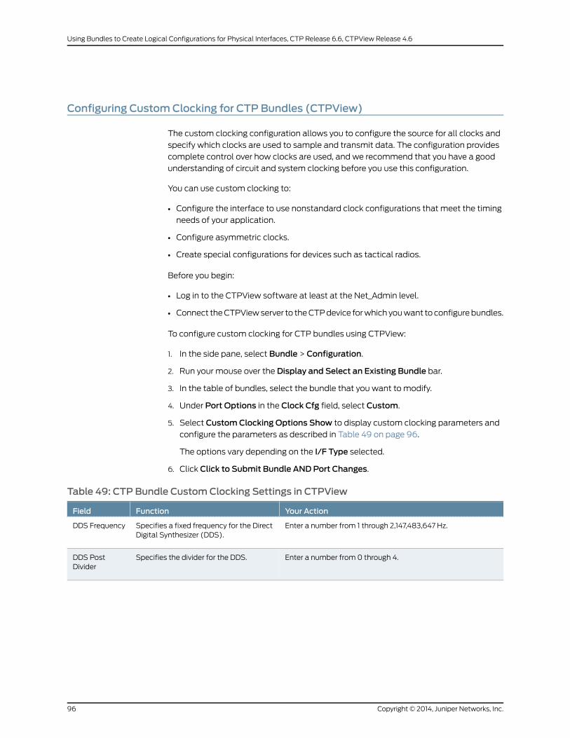
Configuring CustomClocking for CTP Bundles (CTPView)
The custom clocking configuration allows you to configure the source for all clocks and
specify which clocks are used to sample and transmit data. The configuration provides
complete control over how clocks are used, and we recommend that you have a good
understanding of circuit and system clocking before you use this configuration.
You can use custom clocking to:
• Configure the interface to use nonstandard clock configurations that meet the timing
needs of your application.
• Configure asymmetric clocks.
• Create special configurations for devices such as tactical radios.
Before you begin:
• Log in to the CTPView software at least at the Net_Admin level.
• Connect theCTPViewserver to theCTPdevice forwhichyouwant toconfigurebundles.
To configure custom clocking for CTP bundles using CTPView:
1. In the side pane, select Bundle > Configuration.
2. Run your mouse over the Display and Select an Existing Bundle bar.
3. In the table of bundles, select the bundle that you want to modify.
4. Under Port Options in the Clock Cfg field, select Custom.
5. Select CustomClocking Options Show to display custom clocking parameters and
configure the parameters as described in Table 49 on page 96.
The options vary depending on the I/F Type selected.
6. Click Click to Submit Bundle AND Port Changes.
Table 49: CTP Bundle CustomClocking Settings in CTPView
Your ActionFunctionField
Enter a number from 1 through 2,147,483,647 Hz.Specifies a fixed frequency for the DirectDigital Synthesizer (DDS).
DDS Frequency
Enter a number from 0 through 4.Specifies the divider for the DDS.DDS PostDivider
Copyright © 2014, Juniper Networks, Inc.96
Using Bundles to Create Logical Configurations for Physical Interfaces, CTP Release 6.6, CTPView Release 4.6
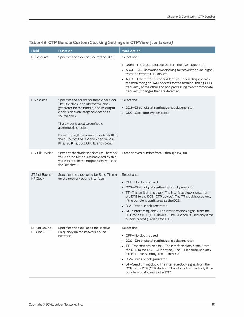
Table 49: CTP Bundle CustomClocking Settings in CTPView (continued)
Your ActionFunctionField
Select one:
• USER—The clock is recovered from the user equipment.
• ADAP—DDSusesadaptiveclocking to recover theclocksignalfrom the remote CTP device.
• AUTO—Use for the autobaud feature. This setting enablesthe monitoring of OAM packets for the terminal timing (TT)frequency at the other end and processing to accommodatefrequency changes that are detected.
Specifies the clock source for the DDS.DDS Source
Select one:
• DDS—Direct digital synthesizer clock generator.
• OSC—Oscillator system clock.
Specifies the source for the divider clock.The DIV clock is an alternative clockgenerator for the bundle, and its outputclock is an even integer divider of itssource clock.
The divider is used to configureasymmetric circuits.
For example, if the sourceclock is 512KHz,the output of the DIV clock can be 256KHz, 128 KHz, 85.333 KHz, and so on.
DIV Source
Enter an even number from 2 through 64,000.Specifies thedivider clockvalue.Theclockvalue of the DIV source is divided by thisvalue to obtain the output clock value ofthe DIV clock.
DIV Clk Divider
Select one:
• OFF—No clock is used.
• DDS—Direct digital synthesizer clock generator.
• TT—Transmit timing clock. The interface clock signal fromthe DTE to the DCE (CTP device). The TT clock is used onlyif the bundle is configured as the DCE.
• DIV—Divider clock generator.
• ST—Send timing clock. The interface clock signal from theDCE to the DTE (CTP device). The ST clock is used only if thebundle is configured as the DTE.
Specifies the clock used for Send Timingon the network bound interface.
ST Net BoundI/F Clock
Select one:
• OFF—No clock is used.
• DDS—Direct digital synthesizer clock generator.
• TT—Transmit timing clock. The interface clock signal fromthe DTE to the DCE (CTP device). The TT clock is used onlyif the bundle is configured as the DCE.
• DIV—Divider clock generator.
• ST—Send timing clock. The interface clock signal from theDCE to the DTE (CTP device). The ST clock is used only if thebundle is configured as the DTE.
Specifies the clock used for ReceiveFrequency on the network boundinterface.
RF Net BoundI/F Clock
97Copyright © 2014, Juniper Networks, Inc.
Chapter 2: Configuring CTP Bundles
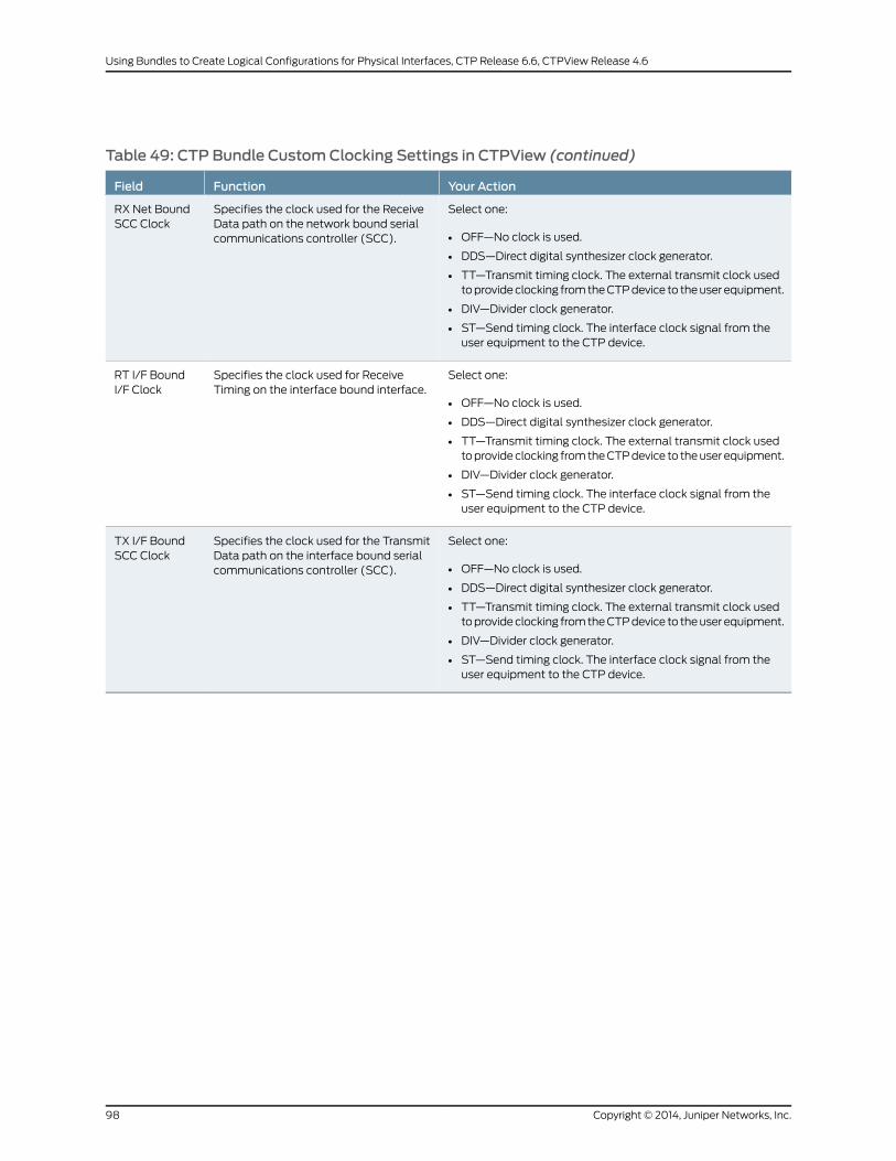
Table 49: CTP Bundle CustomClocking Settings in CTPView (continued)
Your ActionFunctionField
Select one:
• OFF—No clock is used.
• DDS—Direct digital synthesizer clock generator.
• TT—Transmit timing clock. The external transmit clock usedtoprovideclocking fromtheCTPdevice to theuserequipment.
• DIV—Divider clock generator.
• ST—Send timing clock. The interface clock signal from theuser equipment to the CTP device.
Specifies the clock used for the ReceiveData path on the network bound serialcommunications controller (SCC).
RX Net BoundSCC Clock
Select one:
• OFF—No clock is used.
• DDS—Direct digital synthesizer clock generator.
• TT—Transmit timing clock. The external transmit clock usedtoprovideclocking fromtheCTPdevice to theuserequipment.
• DIV—Divider clock generator.
• ST—Send timing clock. The interface clock signal from theuser equipment to the CTP device.
Specifies the clock used for ReceiveTiming on the interface bound interface.
RT I/F BoundI/F Clock
Select one:
• OFF—No clock is used.
• DDS—Direct digital synthesizer clock generator.
• TT—Transmit timing clock. The external transmit clock usedtoprovideclocking fromtheCTPdevice to theuserequipment.
• DIV—Divider clock generator.
• ST—Send timing clock. The interface clock signal from theuser equipment to the CTP device.
Specifies the clock used for the TransmitData path on the interface bound serialcommunications controller (SCC).
TX I/F BoundSCC Clock
Copyright © 2014, Juniper Networks, Inc.98
Using Bundles to Create Logical Configurations for Physical Interfaces, CTP Release 6.6, CTPView Release 4.6

Configuring CustomClocking for CTP Bundles (CTPMenu)
The custom clocking configuration allows you to configure the source for all clocks and
specify which clocks are used to sample and transmit data. The configuration provides
complete control over how clocks are used, and we recommend that you have a good
understanding of circuit and system clocking before you use this configuration.
You can use custom clocking to:
• Configure the interface to use nonstandard clock configurations that meet the timing
needs of your application.
• Configure asymmetric clocks.
• Create special configurations for devices such as tactical radios.
Before you begin:
• Disable the bundle before youmodify the bundle options.
To configure custom clocking for CTP bundles using the CTPMenu:
1. From the CTPMain Menu, select 1) Bundle Operations.
2. Select 1) CTP.
3. Select a bundle from the list.
If you select an active bundle, you are prompted to disable the bundle before
configuring it.
4. Select 3) Port Config.
5. Select 3) Clock Config.
6. Select 1) Port Clock Config.
7. Select Custom.
8. Configure the options as described in Table 50 on page 99.
Table 50: CTP Bundle CustomClocking Settings in the CTPMenu
Your ActionFunctionField
Select:
• User (OI)—Theclock is recovered fromthe user equipment.
• Adaptive—The DDS uses adaptiveclocking to recover the clock signalfrom the remote CTP device.
• Autobaud—This setting enables themonitoring of OAM packets for theterminal timing (TT) frequency at theother end and processing toaccommodate frequency changesthat are detected.
Specifies the clock source for the DDS.DDS Synthesizer Source
99Copyright © 2014, Juniper Networks, Inc.
Chapter 2: Configuring CTP Bundles
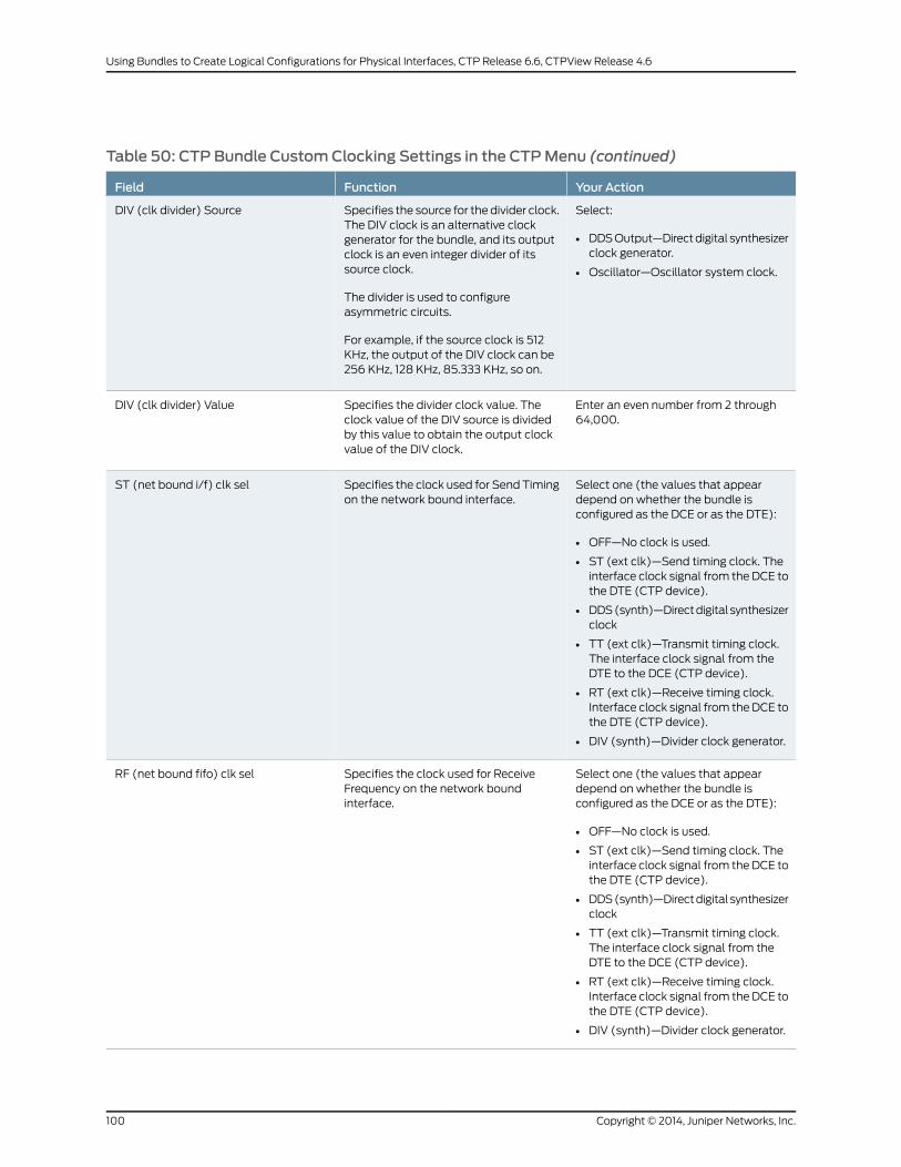
Table 50: CTP Bundle CustomClocking Settings in the CTPMenu (continued)
Your ActionFunctionField
Select:
• DDSOutput—Directdigital synthesizerclock generator.
• Oscillator—Oscillator system clock.
Specifies the source for the divider clock.The DIV clock is an alternative clockgenerator for the bundle, and its outputclock is an even integer divider of itssource clock.
The divider is used to configureasymmetric circuits.
For example, if the source clock is 512KHz, the output of the DIV clock can be256 KHz, 128 KHz, 85.333 KHz, so on.
DIV (clk divider) Source
Enter an even number from 2 through64,000.
Specifies the divider clock value. Theclock value of the DIV source is dividedby this value to obtain the output clockvalue of the DIV clock.
DIV (clk divider) Value
Select one (the values that appeardepend on whether the bundle isconfigured as the DCE or as the DTE):
• OFF—No clock is used.
• ST (ext clk)—Send timing clock. Theinterface clock signal from the DCE tothe DTE (CTP device).
• DDS(synth)—Directdigital synthesizerclock
• TT (ext clk)—Transmit timing clock.The interface clock signal from theDTE to the DCE (CTP device).
• RT (ext clk)—Receive timing clock.Interface clock signal from theDCE tothe DTE (CTP device).
• DIV (synth)—Divider clock generator.
Specifies the clock used for Send Timingon the network bound interface.
ST (net bound i/f) clk sel
Select one (the values that appeardepend on whether the bundle isconfigured as the DCE or as the DTE):
• OFF—No clock is used.
• ST (ext clk)—Send timing clock. Theinterface clock signal from the DCE tothe DTE (CTP device).
• DDS(synth)—Directdigital synthesizerclock
• TT (ext clk)—Transmit timing clock.The interface clock signal from theDTE to the DCE (CTP device).
• RT (ext clk)—Receive timing clock.Interface clock signal from theDCE tothe DTE (CTP device).
• DIV (synth)—Divider clock generator.
Specifies the clock used for ReceiveFrequency on the network boundinterface.
RF (net bound fifo) clk sel
Copyright © 2014, Juniper Networks, Inc.100
Using Bundles to Create Logical Configurations for Physical Interfaces, CTP Release 6.6, CTPView Release 4.6
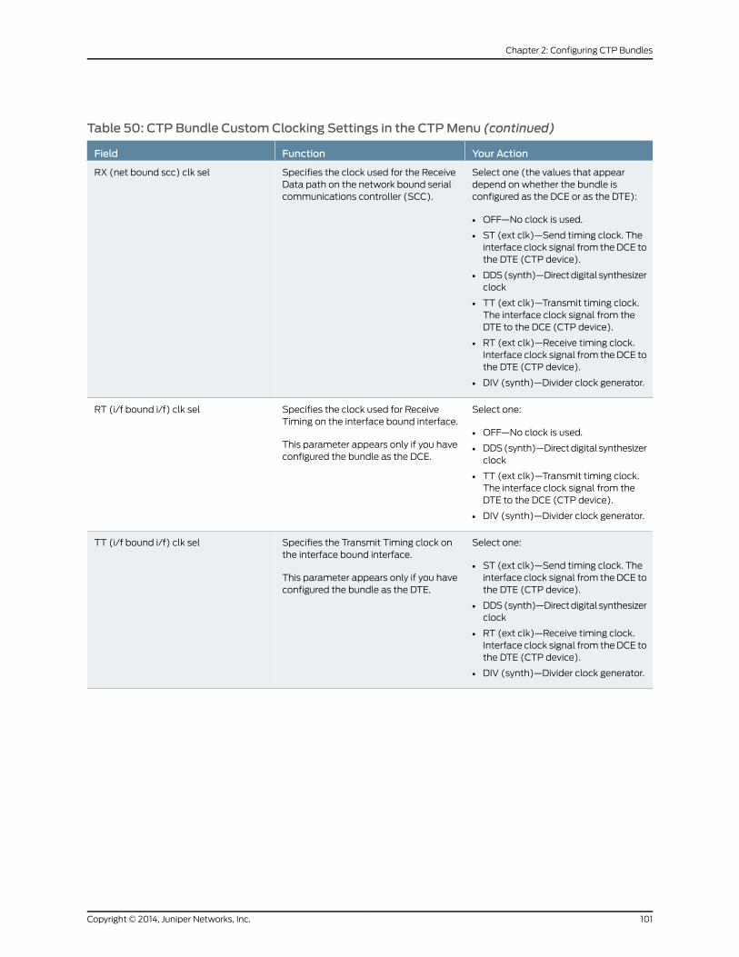
Table 50: CTP Bundle CustomClocking Settings in the CTPMenu (continued)
Your ActionFunctionField
Select one (the values that appeardepend on whether the bundle isconfigured as the DCE or as the DTE):
• OFF—No clock is used.
• ST (ext clk)—Send timing clock. Theinterface clock signal from the DCE tothe DTE (CTP device).
• DDS(synth)—Directdigital synthesizerclock
• TT (ext clk)—Transmit timing clock.The interface clock signal from theDTE to the DCE (CTP device).
• RT (ext clk)—Receive timing clock.Interface clock signal from theDCE tothe DTE (CTP device).
• DIV (synth)—Divider clock generator.
Specifies the clock used for the ReceiveData path on the network bound serialcommunications controller (SCC).
RX (net bound scc) clk sel
Select one:
• OFF—No clock is used.
• DDS(synth)—Directdigital synthesizerclock
• TT (ext clk)—Transmit timing clock.The interface clock signal from theDTE to the DCE (CTP device).
• DIV (synth)—Divider clock generator.
Specifies the clock used for ReceiveTiming on the interface bound interface.
This parameter appears only if you haveconfigured the bundle as the DCE.
RT (i/f bound i/f) clk sel
Select one:
• ST (ext clk)—Send timing clock. Theinterface clock signal from the DCE tothe DTE (CTP device).
• DDS(synth)—Directdigital synthesizerclock
• RT (ext clk)—Receive timing clock.Interface clock signal from theDCE tothe DTE (CTP device).
• DIV (synth)—Divider clock generator.
Specifies the Transmit Timing clock onthe interface bound interface.
This parameter appears only if you haveconfigured the bundle as the DTE.
TT (i/f bound i/f) clk sel
101Copyright © 2014, Juniper Networks, Inc.
Chapter 2: Configuring CTP Bundles
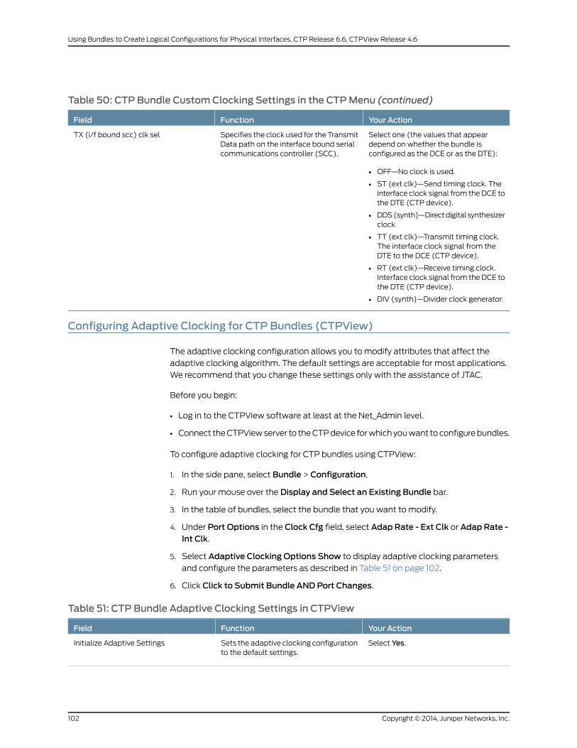
Table 50: CTP Bundle CustomClocking Settings in the CTPMenu (continued)
Your ActionFunctionField
Select one (the values that appeardepend on whether the bundle isconfigured as the DCE or as the DTE):
• OFF—No clock is used.
• ST (ext clk)—Send timing clock. Theinterface clock signal from the DCE tothe DTE (CTP device).
• DDS(synth)—Directdigital synthesizerclock
• TT (ext clk)—Transmit timing clock.The interface clock signal from theDTE to the DCE (CTP device).
• RT (ext clk)—Receive timing clock.Interface clock signal from theDCE tothe DTE (CTP device).
• DIV (synth)—Divider clock generator.
Specifies the clock used for the TransmitData path on the interface bound serialcommunications controller (SCC).
TX (i/f bound scc) clk sel
Configuring Adaptive Clocking for CTP Bundles (CTPView)
The adaptive clocking configuration allows you to modify attributes that affect the
adaptive clocking algorithm. The default settings are acceptable for most applications.
We recommend that you change these settings only with the assistance of JTAC.
Before you begin:
• Log in to the CTPView software at least at the Net_Admin level.
• Connect theCTPViewserver to theCTPdevice forwhichyouwant toconfigurebundles.
To configure adaptive clocking for CTP bundles using CTPView:
1. In the side pane, select Bundle > Configuration.
2. Run your mouse over the Display and Select an Existing Bundle bar.
3. In the table of bundles, select the bundle that you want to modify.
4. Under Port Options in the Clock Cfg field, select Adap Rate - Ext Clk or Adap Rate -Int Clk.
5. Select Adaptive Clocking Options Show to display adaptive clocking parameters
and configure the parameters as described in Table 51 on page 102.
6. Click Click to Submit Bundle AND Port Changes.
Table 51: CTP Bundle Adaptive Clocking Settings in CTPView
Your ActionFunctionField
Select Yes.Sets the adaptive clocking configurationto the default settings.
Initialize Adaptive Settings
Copyright © 2014, Juniper Networks, Inc.102
Using Bundles to Create Logical Configurations for Physical Interfaces, CTP Release 6.6, CTPView Release 4.6

Table 51: CTP Bundle Adaptive Clocking Settings in CTPView (continued)
Your ActionFunctionField
Enter a number from 3 through 200seconds.
Specifies the time period during initialstart of adaptive clocking during whichpacket samples that are experiencingthe least delay through the network arecollected. These samples are used foraggressive state calculations.
Aggressive Calc Period
Enter a number from 3 through 300seconds.
Specifies the time period during normaladaptive clocking during which packetsamples that are experiencing the leastdelay through the network are collected.Thesesamplesareused formaintenancestate calculations.
Maintenance Calc Period
Enter a number from 1 through 100packets per minute.
Specifies the number of packets perminute,which,when reached, causes theadaptive clocking algorithm to changefrom aggressive state to maintenancestate. Lower values result in longerswitchover times with a clock valuecloser to the remote clock.
Slope for Maintenance
Enter a number from 2 through 120seconds.
Specifies how quickly the clockingcorrects to the buffer set point while inmaintenance state.
Maintenance Decay
Enter anumber from1 through200partsper billion.
Specifies a cap for frequencyacceleration, which constrains thefrequency adjustments to the adaptiveclock.
Max Clock Adjustment Value
Enter a number from 1 through 400packets per minute.
Specifies a cap for frequency velocity,which constrains the frequency velocityof the adaptive clock.
Max Clock Offset
Enter a number from 100 through1,000,000microseconds.
Specifies the buffer error rate requiredto change the adaptive clockingalgorithm state frommaintenance toaggressive.
Max Buffer Error
RelatedDocumentation
Adaptive Clocking Overview for CTP Bundles on page 7•
103Copyright © 2014, Juniper Networks, Inc.
Chapter 2: Configuring CTP Bundles

Configuring Adaptive Clocking for CTP Bundles (CTPMenu)
The adaptive clocking configuration allows you to modify attributes that affect the
adaptive clocking algorithm. The default settings are acceptable for most applications.
We recommend that you change these settings only with the assistance of JTAC.
Before you begin:
• Disable the bundle before youmodify the bundle options.
To configure adaptive clocking for CTP bundles using the CTPMenu:
1. From the CTPMain Menu, select 1) Bundle Operations.
2. Select 1) CTP.
3. Select a bundle from the list.
If you select an active bundle, you are prompted to disable the bundle before
configuring it.
4. Select 3) Port Config.
5. Select 3) Clock Config.
6. Select 1) Port Clock Config.
7. Select Set Adaptive Parameters.
8. Configure the options as described in Table 52 on page 104.
Table 52: CTP Bundle Adaptive Clocking Settings in the CTPMenu
Your ActionFunctionField
Select Set to Defaults.Sets the adaptive clocking configurationto the default settings.
Set to Defaults
Enter a number from 3 through 200seconds.
Specifies the time period during initialstart of adaptive clocking during whichpacket samples thatareexperiencing theleast delay through the network arecollected. These samples are used foraggressive state calculations.
AGGR Seconds/Calc
Enter a number from 3 through 300seconds.
Specifies the time period during normaladaptive clocking during which packetsamples that are experiencing the leastdelay through the network are collected.Thesesamplesareused formaintenancestate calculations.
MNTN Seconds/Calc
Copyright © 2014, Juniper Networks, Inc.104
Using Bundles to Create Logical Configurations for Physical Interfaces, CTP Release 6.6, CTPView Release 4.6

Table 52: CTP Bundle Adaptive Clocking Settings in the CTPMenu (continued)
Your ActionFunctionField
Enter a number from 1 through 100packets per minute.
Specifies the number of packets perminute, whichwhen reached, causes theadaptive clocking algorithm to changefrom aggressive state to maintenancestate. Lower values result in longerswitchover times with a clock valuecloser to the remote clock.
Slope for MNTN in ppm
Enter a number from 2 through 120seconds.
Specifies how quickly the clockingcorrects to the buffer set point while inmaintenance state.
Maintenance Decay in calcs
Enter a number from 1 through 1000parts per billion.
Specifies a cap for frequencyacceleration, which constrains thefrequency adjustments to the adaptiveclock.
Max Clock Adjust in ppb
Enter a number from 1 through 400packets per minute.
Specifies a cap for frequency velocity,which constrains the frequency velocityof the adaptive clock.
Max Clock Offset in ppm
Enter a number from 100 through1,000,000 seconds.
Specifies the buffer error rate required tochange the adaptive clocking algorithmstate frommaintenance to aggressive.
Max Buffer Error in usec
RelatedDocumentation
Adaptive Clocking Overview for CTP Bundles on page 7•
Network Node Reference Overview
Network node reference (NetRef) is an extension of the CTP adaptive port clocking.
NetRef can be used to provide node level synchronization across a network. NetRef is
supported in CTPOS release 5.4R1 and later.
NetRef operates in twomodes.
• Primary or backup operation—When NetRef is configured for primary or backup
operation, theprimarynodesendsclocking information to thebackupnode.Thebackup
node uses an algorithm similar to that used for adaptive port clocking to control the
local nodeclock so that it follows theclockingof the remotenode. Tooperate inprimary
or backupmode, the remote primary nodemust be configured as a NetRef primary
node with the IP address of the NetRef slave configured. The backup nodemust be
configured as a NetRef backup node with the IP address of the NetRef primary node
configured.
• Adaptive bundle operation— Normally, the adaptive clocking algorithm is used to
control the port clock, but when NetRef is configured for adaptive bundle operation,
the adaptive clocking algorithm instead controls the node clock. The clocking for the
whole node is then derived from the clock that drives the remote port. If the remote
port is configured for TT, then the local node is clocked to the remote port's external
105Copyright © 2014, Juniper Networks, Inc.
Chapter 2: Configuring CTP Bundles
clock. If the remote port is configured for configured rate, then the local node clock is
derived from the remote node clock.
Whenanode is configured forNetRefbackuporadaptivebundleoperation, all theexternal
references must be disabled. If timing packets stop arriving at a NetRef backup node ,
the backup node waits until packets start arriving again tomake any clock adjustments.
When the packets start arriving again, NetRef transitions toWait state, waits for 16packets, and then transitions to theAggressivestate.TheLEDbecomes redwhenNetRefis inWait or Aggressive state. The LED is green when NetRef is inMaintain state.
Guidelines for Configuring NetRef
• You can configure the NetRef adaptive parameters from the port menu. However, you
cannot modify the adaptive parameters of a NetRef backup node.
• If a CTP bundle is already configured between the two nodes, using NetRef adaptive
bundle operation does not add to the network traffic between the nodes.
• Though NetRef is supported only on CTPOS 5.4R1 and later, it supports remote nodes
running earlier CTPOS versions. No special configuration needs to bemade on the
remote node.
• Themaximumnumber of backupnodes that aNetRef primary nodecanhave is limited
to 10.However, there is no limit on thenumber of backupnodes for theNetRef adaptive
bundle operation.
• Adaptive bundle operation depends on the bundle state and requires a CTP bundle
between thenodes. Thenodesynchronizationprocess stops if thebundle comesdown.
NetRef primary or master operation does not need a CTP bundle between the nodes.
RelatedDocumentation
Configuring NetRef for Adaptive Bundle Operation on page 107•
• Configuring NetRef for Primary or Backup Operation on page 108
Copyright © 2014, Juniper Networks, Inc.106
Using Bundles to Create Logical Configurations for Physical Interfaces, CTP Release 6.6, CTPView Release 4.6

Configuring NetRef for Adaptive Bundle Operation
For NetRef adaptive bundle operation, the adaptive calculations are used tomanage the
node clock instead of the port clock as is done for a standard adaptive bundle.When the
port is activated, the CTP device verifies whether:
• The port configured for adaptive clocking.
• NetRef is configured for adaptive port operation.
• The bundle number matches the bundle number that is configured in NetRef.
If the above requirements are met, a flag is set to indicate that the adaptive calculation
for the port should manage the node clock instead of the port clock. The adjustment
range in the adaptive calculation is limited to 0–4095 and is not set by the adaptive
parametermaxppboffset. The port adaptive calculation continues tomanage the nodeclock until the bundle is disabled.
To configure network node reference for adaptive bundle operation:
1. From theMainMenu, select 2) Node Synchronization
2. Select 6) NetRef.
3. From the NetRef Menu, select 1) NetRef.
Enable NetRef (0=Off, 1=Master, 2=Slave, 3=Adaptive Bundle)? (0-3)[2]:
4. Enter 3 to select Adaptive Bundle.
5. Select 2) Adaptive Bundle and specify the bundle number.
When you configure a node for NetRef adaptive bundle operation, youmust specify
the bundle number in the NetRef menu.
For adaptive bundle operation, the bundlemust be configured for adaptive clocking and
must be activated after you configure NetRef. NetRef adaptive bundle operation starts
only after the bundle that is configured is activated. NetRef is disabled when you disable
the bundle. To use the bundle without the NetRef feature, youmust first disable the
bundle, turn off NetRef adaptive bundle operation, and then re-enable the bundle.
RelatedDocumentation
Network Node Reference Overview on page 105•
• Configuring NetRef for Primary or Backup Operation on page 108
107Copyright © 2014, Juniper Networks, Inc.
Chapter 2: Configuring CTP Bundles
Configuring NetRef for Primary or Backup Operation
NetRef primary backup operation involves a new packet flow from the primary node to
all thebackupnodes. These timingpacketsare sentata rateofapproximately4.5packets
per second.
NOTE: In this topic, the terms Primary and Backup refer tomaster and slaveoperations or nodes, respectively.
To configure network node reference for primary or backup operation:
1. From the Main Menu, select 2) Node Synchronization
2. Select 6) NetRef
3. From the NetRef Menu, 1) NetRef.
Enable NetRef (0=Off, 1=Master, 2=Slave, 3=Adaptive Bundle)? (0-3)[2]:
4. Enter 1 to select Master mode or 2 to select Slave mode.
5. Select 2) Remote Address and specify the IP address of the NetRef slave.
NOTE: When a node is configured for NetRef backup operation, the remoteaddressmust be configured to that of theprimary node. Likewise, theNetRefprimary nodemust be configured with the IP address of the NetRef backupnode. A NetRef primary node can be configured to send data packets to upto 10 NetRef backup nodes.
RelatedDocumentation
• Configuring NetRef for Adaptive Bundle Operation on page 107
• Network Node Reference Overview on page 105
Copyright © 2014, Juniper Networks, Inc.108
Using Bundles to Create Logical Configurations for Physical Interfaces, CTP Release 6.6, CTPView Release 4.6
PART 2
Administration
• Activating, Disabling, Deleting, or Recentering CTP Bundles on page 111
• Querying CTP Bundles on page 113
• MonitoringPacketCreationandReceptionandPacketDelay forCTPBundlesonpage 121
• Diagnostic Testing for CTP Bundles Overview on page 125
• Configuring Diagnostic Testing for CTP Bundles on page 129
• Displaying BERT Status and Counters for CTP Bundles on page 135
• Reducing the Number of SNMP Traps Generated for Late and Missing
Packets on page 139
109Copyright © 2014, Juniper Networks, Inc.

Copyright © 2014, Juniper Networks, Inc.110
Using Bundles to Create Logical Configurations for Physical Interfaces, CTP Release 6.6, CTPView Release 4.6
CHAPTER 3
Activating, Disabling, Deleting, orRecentering CTP Bundles
• Activating, Disabling, Deleting, or Recentering CTP Bundles (CTPView) on page 111
• Activating, Disabling, Deleting, or Recentering for CTPBundles (CTPMenu) on page 111
Activating, Disabling, Deleting, or Recentering CTP Bundles (CTPView)
This topic describes how to change the status of bundles. You can recenter only active
CTP and SAToP bundles.
Before you begin:
• Log in to the CTPView software at least at the Net_Admin level.
• Connect theCTPViewserver to theCTPdevice forwhichyouwant tochange thestatus
of the bundles.
To change the status of bundles:
1. In the side pane, select Bundle > Change Status.
2. Select the appropriate boxes and click Submit.
Activating, Disabling, Deleting, or Recentering for CTP Bundles (CTPMenu)
You can recenter only active CTP bundles.
To activate, disable, delete, or recenter bundles using the CTPMenu:
1. From the CTPMain Menu, select 1) Bundle Operations.
2. Select the type of bundle.
3. Select a bundle from the list.
4. From themenu, select the option that you want to perform on the bundle:
• 4) Activate
• 5) Disable
111Copyright © 2014, Juniper Networks, Inc.

• 6) Recenter
Copyright © 2014, Juniper Networks, Inc.112
Using Bundles to Create Logical Configurations for Physical Interfaces, CTP Release 6.6, CTPView Release 4.6
CHAPTER 4
Querying CTP Bundles
• Displaying Running CTP Bundle Configuration, State, and Counters
(CTPView) on page 113
• Displaying Running CTP Bundle Configuration, State, and Counters (CTP
Menu) on page 116
Displaying Running CTP Bundle Configuration, State, and Counters (CTPView)
This topic describes how to display the running configuration of your bundle, along with
the state and various counters.
Before you begin:
• Log in to the CTPView software at least at the Net_Admin level.
• Connect theCTPViewserver to theCTPdevice forwhichyouwant tochange thestatus
of the bundles.
To view information about the bundle:
1. In the side pane, select Bundle > RuntimeQuery.
2. Run your mouse over theMouseOver to Display and Select Bundles to Display bar.
3. In the table of bundles, select the bundles that you want to view, and click DisplaySelected Bundles. To select multiple bundles, hold down the CTRL key.
The configuration of the bundle or bundles appears followed by the runtime state
and counters.
Table 53 on page 114 describes the fields in the state and counters sections of the
display.
The signaling configuration appears only if you changed the signaling configuration
from the default configuration.
113Copyright © 2014, Juniper Networks, Inc.
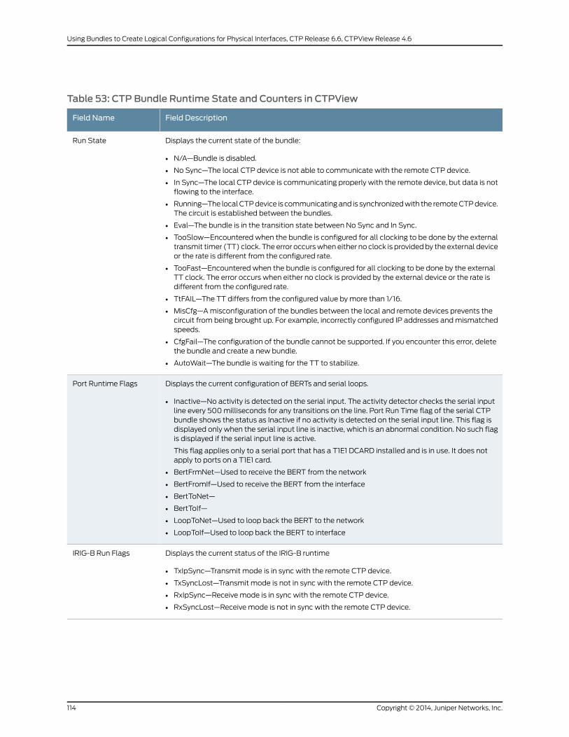
Table 53: CTP Bundle Runtime State and Counters in CTPView
Field DescriptionField Name
Displays the current state of the bundle:
• N/A—Bundle is disabled.
• No Sync—The local CTP device is not able to communicate with the remote CTP device.
• In Sync—The local CTP device is communicating properly with the remote device, but data is notflowing to the interface.
• Running—The localCTPdevice is communicatingand is synchronizedwith the remoteCTPdevice.The circuit is established between the bundles.
• Eval—The bundle is in the transition state between No Sync and In Sync.
• TooSlow—Encountered when the bundle is configured for all clocking to be done by the externaltransmit timer (TT) clock. The error occurswhen either no clock is providedby the external deviceor the rate is different from the configured rate.
• TooFast—Encountered when the bundle is configured for all clocking to be done by the externalTT clock. The error occurs when either no clock is provided by the external device or the rate isdifferent from the configured rate.
• TtFAIL—The TT differs from the configured value by more than 1/16.
• MisCfg—Amisconfiguration of the bundles between the local and remote devices prevents thecircuit from being brought up. For example, incorrectly configured IP addresses andmismatchedspeeds.
• CfgFail—The configuration of the bundle cannot be supported. If you encounter this error, deletethe bundle and create a new bundle.
• AutoWait—The bundle is waiting for the TT to stabilize.
Run State
Displays the current configuration of BERTs and serial loops.
• Inactive—No activity is detected on the serial input. The activity detector checks the serial inputline every 500milliseconds for any transitions on the line. Port Run Time flag of the serial CTPbundle shows the status as Inactive if no activity is detected on the serial input line. This flag isdisplayed only when the serial input line is inactive, which is an abnormal condition. No such flagis displayed if the serial input line is active.
This flag applies only to a serial port that has a T1E1 DCARD installed and is in use. It does notapply to ports on a T1E1 card.
• BertFrmNet—Used to receive the BERT from the network
• BertFromIf—Used to receive the BERT from the interface
• BertToNet—
• BertToIf—
• LoopToNet—Used to loop back the BERT to the network
• LoopToIf—Used to loop back the BERT to interface
Port Runtime Flags
Displays the current status of the IRIG-B runtime
• TxIpSync—Transmit mode is in sync with the remote CTP device.
• TxSyncLost—Transmit mode is not in sync with the remote CTP device.
• RxIpSync—Receive mode is in sync with the remote CTP device.
• RxSyncLost—Receive mode is not in sync with the remote CTP device.
IRIG-B Run Flags
Copyright © 2014, Juniper Networks, Inc.114
Using Bundles to Create Logical Configurations for Physical Interfaces, CTP Release 6.6, CTPView Release 4.6
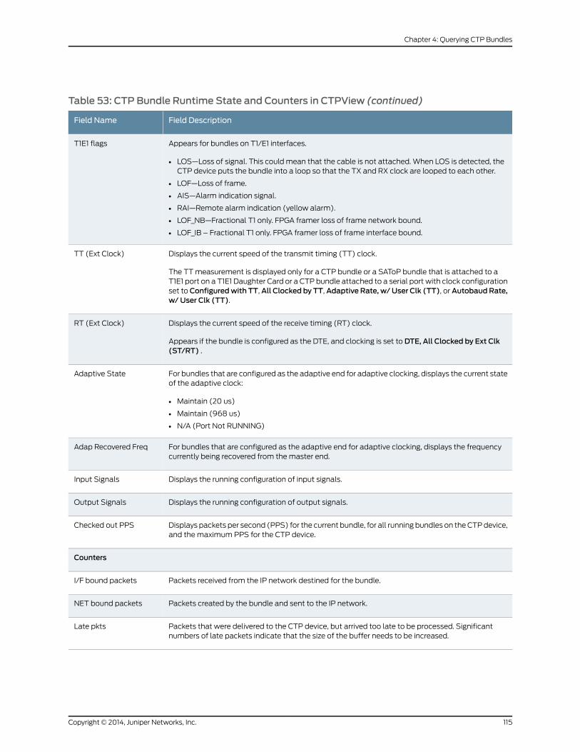
Table 53: CTP Bundle Runtime State and Counters in CTPView (continued)
Field DescriptionField Name
Appears for bundles on T1/E1 interfaces.
• LOS—Loss of signal. This could mean that the cable is not attached. When LOS is detected, theCTP device puts the bundle into a loop so that the TX and RX clock are looped to each other.
• LOF—Loss of frame.
• AIS—Alarm indication signal.
• RAI—Remote alarm indication (yellow alarm).
• LOF_NB—Fractional T1 only. FPGA framer loss of frame network bound.
• LOF_IB – Fractional T1 only. FPGA framer loss of frame interface bound.
T1E1 flags
Displays the current speed of the transmit timing (TT) clock.
The TTmeasurement is displayed only for a CTP bundle or a SAToP bundle that is attached to aT1E1 port on a T1E1 Daughter Card or a CTP bundle attached to a serial port with clock configurationset toConfiguredwith TT,All Clocked by TT,Adaptive Rate, w/User Clk (TT), orAutobaudRate,w/ User Clk (TT).
TT (Ext Clock)
Displays the current speed of the receive timing (RT) clock.
Appears if the bundle is configured as the DTE, and clocking is set to DTE, All Clocked by Ext Clk(ST/RT) .
RT (Ext Clock)
For bundles that are configured as the adaptive end for adaptive clocking, displays the current stateof the adaptive clock:
• Maintain (20 us)
• Maintain (968 us)
• N/A (Port Not RUNNING)
Adaptive State
For bundles that are configured as the adaptive end for adaptive clocking, displays the frequencycurrently being recovered from themaster end.
Adap Recovered Freq
Displays the running configuration of input signals.Input Signals
Displays the running configuration of output signals.Output Signals
Displays packets per second (PPS) for the current bundle, for all running bundles on theCTPdevice,and themaximum PPS for the CTP device.
Checked out PPS
Counters
Packets received from the IP network destined for the bundle.I/F bound packets
Packets created by the bundle and sent to the IP network.NET bound packets
Packets that were delivered to the CTP device, but arrived too late to be processed. Significantnumbers of late packets indicate that the size of the buffer needs to be increased.
Late pkts
115Copyright © 2014, Juniper Networks, Inc.
Chapter 4: Querying CTP Bundles

Table 53: CTP Bundle Runtime State and Counters in CTPView (continued)
Field DescriptionField Name
Packets that were not delivered to the CTP in time to process out the serial interface because theywere either late or dropped by the IP network.
Each timeapacket ismissed, thedata fill pattern specified in theadvancedportoptions is substitutedfor data in the missed packet. The substitution maintains the bit count integrity of the data sent tothe DTE or encryptor, but results in what appears to be a burst of errors with a duration equal to thesize of the packet.
Missing pkts
Number of times the buffer was restarted.Buffer restarts
Number of times that the average buffer state was less than theminimum buffer setting.Buffer underflows
Number of times that the buffer state exceeded themaximum buffer setting.Buffer overflows
Indicates an exceeded threshold. The CTP device is designed to tolerate strings of consecutivemissing packets without the loss of bit count integrity. The number of packets is configurable; thedefault is five. Exceeding this threshold is called a starvation, and a counter is incremented eachtime this event occurs.
Buffer starves
Largest buffer sample observed.Buffer max samples
Maximum, average, andminimum buffer sizes observed.Buff Max/Avg/Min
Maximum, average, andminimum buffer sizes observed in the last minute.Buff Last Minute
Number of seconds the current update has been running.BERT running sec
Number of seconds that the local CTP device has been in sync with the remote CTP device.BERT sync sec
Number of seconds during which there were errors.BERT error sec
Shows whether the CTP device is currently in sync with the remote CTP deviceBERT in sync
Indicates the last time that the system counters were reset.Last counter clear
Displaying Running CTP Bundle Configuration, State, and Counters (CTPMenu)
To display a bundle using the CTPMenu:
1. From the CTPMain Menu, select 1) Bundle Operations.
2. Select the type of bundle.
3. Select a bundle from the list.
4. From themenu, select 1) Query. The configuration of the bundle appears followed bythe runtime state and counters.
Table 54 on page 117 describes the fields in the state and counters sections of the
display.
Copyright © 2014, Juniper Networks, Inc.116
Using Bundles to Create Logical Configurations for Physical Interfaces, CTP Release 6.6, CTPView Release 4.6
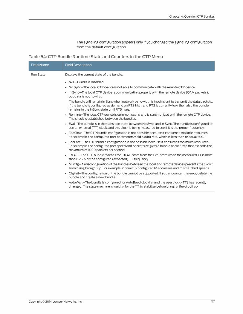
The signaling configuration appears only if you changed the signaling configuration
from the default configuration.
Table 54: CTP Bundle Runtime State and Counters in the CTPMenu
Field DescriptionField Name
Displays the current state of the bundle:
• N/A—Bundle is disabled.
• No Sync—The local CTP device is not able to communicate with the remote CTP device.
• In Sync—The local CTP device is communicating properly with the remote device (OAM packets),but data is not flowing.
The bundle will remain In Sync when network bandwidth is insufficient to transmit the data packets.If the bundle is configured as demand on RTS high, and RTS is currently low, then also the bundleremains in the InSync state until RTS rises.
• Running—The local CTP device is communicating and is synchronized with the remote CTP device.The circuit is established between the bundles.
• Eval—The bundle is in the transition state between No Sync and In Sync. The bundle is configured touse an external (TT) clock, and this clock is being measured to see if it is the proper frequency.
• TooSlow—The CTP bundle configuration is not possible because it consumes too little resources.For example, the configured port parameters yield a data rate, which is less than or equal to 0.
• TooFast—The CTP bundle configuration is not possible because it consumes toomuch resources.For example, the configured port speed and packet size gives a bundle packet rate that exceeds themaximum of 1000 packets per second.
• TtFAIL—The CTP bundle reaches the TtFAIL state from the Eval state when themeasured TT ismorethan 6.25% of the configured (expected) TT frequency
• MisCfg—Amisconfiguration of the bundles between the local and remote devices prevents the circuitfrom being brought up. For example, incorrectly configured IP addresses andmismatched speeds.
• CfgFail—The configuration of the bundle cannot be supported. If you encounter this error, delete thebundle and create a new bundle.
• AutoWait—The bundle is configured for AutoBaud clocking and the user clock (TT) has recentlychanged. The state machine is waiting for the TT to stabilize before bringing the circuit up.
Run State
117Copyright © 2014, Juniper Networks, Inc.
Chapter 4: Querying CTP Bundles

Table 54: CTP Bundle Runtime State and Counters in the CTPMenu (continued)
Field DescriptionField Name
Displays the current configuration of BERTs and serial loops.
• SdInactive—No activity is detected on the serial input. The activity detector checks the serial inputline every 500milliseconds for any transitions on the line. Port RunTime flag of the serial CTPbundleshows the status as Inactive if no activity is detected on the serial input line. This flag is displayedonly when the serial input line is inactive, which is an abnormal condition. No such flag is displayedif the serial input line is active.
This flag applies only to a serial port that has a T1E1 DCARD installed and is in use. It does not applyto ports on a T1E1 card.
• BertFrmNet—Receive BERT for this port is active and ismonitoring the interface bound data. ReceiveBERT is only a monitoring function and does not affect the interface bound data.
• BertFromIf—Receive BERT for this port is active and is monitoring the network bound data. ReceiveBERT is only a monitoring function and does not affect the network bound data.
• BertToNet—Transmit BERT for this port is active and is sending the network bound data, therebyinterrupting the normal data path from the interface.
• BertToIf—Transmit BERT for this port is active and is sending the interface bound data, therebyinterrupting the normal data path from the IP network.
• LoopToNet—Interface bound data is looped back towards the IP network, thereby interrupting thenormal network bound data. Interface bound data is not interrupted.
• LoopToIf—Networkbounddata is loopedback towards the interface, thereby interrupting the interfacebound data. Network bound data is not interrupted.
Port Runtime Flags
Displays the current status of the IRIG-B runtime
• TxIpSync—Transmit mode is in sync with the remote CTP device. The local IRIGmodule is able torecover the framed IRIG signal from the data arriving from the remote IRIGmodule through the IPnetwork.
• TxSyncLost—Transmit mode is not in sync with the remote CTP device. This flag is set whenever theTxIpSync flag is active after issuing the last port counter clear command. When activated, it remainsactive until you issue the next port counter clear command.
• RxIrigSync—Receive mode is in sync with the remote CTP device. The local IRIGmodule is able torecover the IRIG signal from the data arriving from the IRIG signal arriving at the interface.
• RxSyncLost—Receive mode is not in sync with the remote CTP device. This flag is set when theRxIrigSync flag is active after issuing the last port counter clear command.When activated, it remainsactive until you issue the next port counter clear command.
IRIG-B Run Flags
Appears for bundles on T1/E1 interfaces.
• LOS—Loss of signal. This could mean that the cable is not attached. When LOS is detected, the CTPdevice puts the bundle into a loop so that the TX and RX clock are looped to each other.
• LOF—Loss of frame.
• AIS—Alarm indication signal.
• RAI—Remote alarm indication (yellow alarm).
• LOF_NB—Fractional T1 only. FPGA framer loss of frame network bound.
• LOF_IB – Fractional T1 only. FPGA framer loss of frame interface bound.
T1E1 flags
Displays the current speed of the transmit timing (TT) clock.
The TTmeasurement is displayed only for a CTP bundle or a SAToP bundle that is attached to a T1E1port on a T1E1 Daughter Card or a CTP bundle attached to a serial port with clock configuration set toConfiguredwith TT, All Clocked by TT, Adaptive Rate, w/ User Clk (TT), or Autobaud Rate, w/ UserClk (TT).
TT (Ext Clock)
Copyright © 2014, Juniper Networks, Inc.118
Using Bundles to Create Logical Configurations for Physical Interfaces, CTP Release 6.6, CTPView Release 4.6

Table 54: CTP Bundle Runtime State and Counters in the CTPMenu (continued)
Field DescriptionField Name
Displays the current speed of the receive timing (RT) clock.
Appears if thebundle is configuredas theDTE, andclocking is set toDTE,AllClockedbyExtClk (ST/RT).
RT (Ext Clock)
For bundles that are configured as the adaptive end for adaptive clocking, displays the current state ofthe adaptive clock:
• Aggressive—Bundle is running, and adaptive clocking is in training mode.
• Maintain (20 us)—Bundle is running, and adaptive clocking is in steady state. The value specifiedparentheses is the current offset from the optimal buffer level.When adaptive clocking is functioningproperly, it should hover around 0.
• N/A (Port Not RUNNING)—Bundle is disabled.
Adaptive State
For bundles that are configured as the adaptive end for adaptive clocking, displays the frequencycurrently being recovered from themaster end.
Adap RecoveredFreq
Displays the running configuration of input signals.Input Signals
Displays the running configuration of output signals.Output Signals
Displays packets per second (PPS) for the current bundle, for all running bundles on the CTP device,and themaximum PPS for the CTP device.
Checked out PPS
Displays the running configuration of input signals.Input Signals
Displays the running configuration of output signals.Output Signals
Displays packets per second (PPS) for the current bundle, for all running bundles on the CTP device,and themaximum PPS for the CTP device.
Checked out PPS
Counters
Packets received from the IP network destined for the bundle.I/F bound packets
Packets created by the bundle and sent to the IP network.NET bound packets
Packets thatwere delivered to theCTPdevice, but arrived too late to be processed. Significant numbersof late packets indicate that the size of the buffer needs to be increased.
Late pkts
Packets thatwere not delivered to the CTP in time to process out the serial interface because theywereeither late or dropped by the IP network.
Each time a packet is missed, the data fill pattern specified in the advanced port options is substitutedfor data in the missed packet. The substitution maintains the bit count integrity of the data sent to theDTE or encryptor, but results in what appears to be a burst of errors with a duration equal to the size ofthe packet.
Missing pkts
Packets thatwere delivered to theCTPdevice, but arrived too late to be processed. Significant numbersof late packets indicate that the size of the buffer needs to be increased.
Late pkts
119Copyright © 2014, Juniper Networks, Inc.
Chapter 4: Querying CTP Bundles
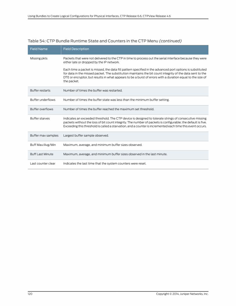
Table 54: CTP Bundle Runtime State and Counters in the CTPMenu (continued)
Field DescriptionField Name
Packets thatwere not delivered to the CTP in time to process out the serial interface because theywereeither late or dropped by the IP network.
Each time a packet is missed, the data fill pattern specified in the advanced port options is substitutedfor data in the missed packet. The substitution maintains the bit count integrity of the data sent to theDTE or encryptor, but results in what appears to be a burst of errors with a duration equal to the size ofthe packet.
Missing pkts
Number of times the buffer was restarted.Buffer restarts
Number of times the buffer state was less than theminimum buffer setting.Buffer underflows
Number of times the buffer reached themaximum set threshold.Buffer overflows
Indicates an exceeded threshold. The CTP device is designed to tolerate strings of consecutive missingpacketswithout the loss of bit count integrity. The number of packets is configurable; the default is five.Exceeding this threshold is calleda starvation, anda counter is incrementedeach time this event occurs.
Buffer starves
Largest buffer sample observed.Buffer max samples
Maximum, average, andminimum buffer sizes observed.Buff Max/Avg/Min
Maximum, average, andminimum buffer sizes observed in the last minute.Buff Last Minute
Indicates the last time that the system counters were reset.Last counter clear
Copyright © 2014, Juniper Networks, Inc.120
Using Bundles to Create Logical Configurations for Physical Interfaces, CTP Release 6.6, CTPView Release 4.6

CHAPTER 5
MonitoringPacketCreationandReceptionand Packet Delay for CTP Bundles
• Using SCC Counts to Monitor Packet Creation and Reception for CTP Bundles (CTP
Menu) on page 121
• UsingBufferSampling toMonitorPacketDelay forCTPBundles (CTPMenu)onpage 122
Using SCC Counts toMonitor Packet Creation and Reception for CTP Bundles (CTPMenu)
Serial Communications Controller (SCC) counts provide detail about packet creation
and reception for a CTP bundle.
You cannot display SCC counts in CTPView.
To display SCC counts using the CTPMenu:
1. From the CTPMain Menu, select 1) Bundle Operations.
2. Select the type of bundle.
3. Select a bundle from the list.
4. Select 8) Runtime Diags.
5. Select 7) SCC Counts.
A list of packet counters appears. Table 55 on page 121 describes the counters.
Table 55: Statistics for Packet Creation and Reception for CTP Bundles in the CTPMenu
DescriptionField Name
Packets to network from interface. Number of packets that were sent to the IP network from theinterface.
Pkts to NET from I/F
Packets tonetwork interrupts.Numberofpacketsdestined for the IPnetwork thatwereprocessedby the software.
Pkts to NET ints
Packets to interface from network. Number of packets that were sent to the interface from theIP network.
Pkts to I/F from NET
121Copyright © 2014, Juniper Networks, Inc.
Table 55: Statistics for Packet Creation and Reception for CTP Bundles in the CTPMenu (continued)
DescriptionField Name
Packets to interface interrupts. Number of packets destined for the interface that were processedby the software driver.
Pkts to I/F ints
Packets to interfacemissing. Number of packets destined for the interface thatwere not availablewhen the data was needed. Unavailability can be caused by a dropped packet in the IP networkor a delayed packet considered late by the CTP device according to the current buffer settingsand state.
Pkts to I/F missing
Packets to interface late.Numberofpacketsdestined for the serial interface thatwerenotavailablewhen the data was needed. Unavailability can be caused by a dropped packet in the IP networkor a delayed packet considered late by the CTP device according to the current buffer settingsand state.
Pkts to I/F late
Packets to interface recenter count. Number of buffer recenters since the last time statistics werecleared. Recenters are causedbyeither buffer underflow(buffer depleted)or thebuffer exceedingthe maximum delay configured for the bundle.
Under normal operations, the buffer recenter count should not increment. If the count isincrementing, check both the clocking configuration and the reference clocks being used by theCTP device. For example, if the local and remote ends of the bundle are configure with slightlydifferent rates, buffer recenterswill result. If theaccuracyor stability of the references is inaccurate,recenters may also occur.
Pkts to I/F recenter cnt
Packets to interfaceunderflowcount. Number of times theminimumthresholdwas reached sincethe counter was last reset.
Pkts to I/F underflow cnt
Packets to interface overflow count. Number of times theminimum threshold was reached sincethe counter was last reset.
Pkts to I/F overflow cnt
Packets to interface starvation count. Number of times the CTP device considered the bundle tobe in a starvation condition. The CTP receive processor considers a starvation condition to bewhen a fixed consecutive number of packets are missing from the IP network. During this state,the buffer is recentered. Starvation can occur because of a failure in the IP network or because ofa cabling or Ethernet interface problem.
Pkts to I/F starve cnt
Using Buffer Sampling toMonitor Packet Delay for CTP Bundles (CTPMenu)
The CTP device uses buffer sampling tomonitor packet delay. Buffer samples are based
on the amount of time that packets are in the buffer. The time is measured fromwhen
a packet arrives from the Ethernet interface to when it is transmitted out the serial
interface.
You cannot display buffer sampling in CTPView.
To display buffer for a CTP bundle using the CTPMenu:
1. From the CTPMain Menu, select 1) Bundle Operations.
2. Select the type of bundle.
3. Select a bundle from the list.
Copyright © 2014, Juniper Networks, Inc.122
Using Bundles to Create Logical Configurations for Physical Interfaces, CTP Release 6.6, CTPView Release 4.6

4. Select 8) Runtime Diags.
5. Select 8) Buffer Query.
A list of buffer counts appears. Table 56 on page 123 describes the fields in the buffer
counts.
Table 56: Buffer Counts for CTP Bundles in the CTPMenu
DescriptionField Name
Number of packets measured since the last time the count was cleared.Total Samples
Within the total number of samples, the smallest sample measured in milliseconds.Packets in this sample experienced themost delay.
Smallest Sample
Within the total number of samples, the average buffer fill, in milliseconds.Average Sample
Within the total numberof samples, the largest samplemeasured inmilliseconds.Packetsin this sample experienced the least delay.
Largest Sample
Difference between the largest sample measured and the smallest sample measured, inmilliseconds. This number corresponds to system packet delay jitter.
Largest Buffer Jitter
123Copyright © 2014, Juniper Networks, Inc.
Chapter 5: Monitoring Packet Creation and Reception and Packet Delay for CTP Bundles

Copyright © 2014, Juniper Networks, Inc.124
Using Bundles to Create Logical Configurations for Physical Interfaces, CTP Release 6.6, CTPView Release 4.6

CHAPTER 6
Diagnostic Testing for CTP BundlesOverview
• Serial Loops for CTP Bundles Overview on page 125
• BERT Testing for CTP Bundles Overview on page 126
• End-to-End BERT for CTP Bundles Overview on page 127
Serial Loops for CTP Bundles Overview
You can use serial loops to diagnose issues in your network. You set up serial loops in the
following directions:
• Toward the serial interface and the attached customer device.
• Toward the IP network and the remote customer device.
Serial loops may not run on transparent circuits. The serial loop function connects the
SD and RD signals of the interface (in the direction specified), and will work only if a
transparent circuit uses the SD and RD signals to transport data.
Normal Data Flow in the CTPNetwork
Figure 15 on page 125 shows the normal data flow through the network.
Figure 15: Normal Data Flow
IP network
g015
431
CTP deviceCTP deviceCustomerEquipment
CustomerEquipment
Serial Loop to the Serial Interface
Figure 16 on page 126 shows the data flow for a serial loop to the interface and the local
customer device.
The serial loop toward the interface loops data arriving from the serial interface that is
destined for the IP network back to the serial interface. The data is still transmitted from
125Copyright © 2014, Juniper Networks, Inc.

the serial interface to the IP network, but data from the IP network to the serial interface
is blocked.
Figure 16: Serial Loop to the Interface
IP networkCustomerEquipment
g015
433
CTP deviceCTP deviceCustomerEquipment
Serial Loop to the Network
Figure 17 on page 126 shows the data flow for a serial loop toward the network.
Serial loops toward the IPnetwork loopsdataarriving fromthe IPnetwork that is destined
for the serial interface back to the IP network and the remote customer device. The data
is still transmitted from the IP network to the serial interface, but data from the serial
interface to the IP network and the remote customer device is blocked.
Figure 17: Serial Loop to the Network
IP network
g015
432
CTP deviceCTP deviceCustomerEquipment
CustomerEquipment
RelatedDocumentation
Configuring Serial Loops for CTP Bundles (CTPMenu) on page 130•
• Configuring Serial Loops for CTP Bundles (CTPView) on page 129
BERT Testing for CTP Bundles Overview
The CTP series provides Bit Error Rate Tests (BERT) for bundles. Each bundle can have
aBERT transmitter and receiver that can transmit and receiveapseudorandomsequence
of data using a pattern that you specify. You can set up the BERT to transmit the data
sequence toward the serial interface or toward the IP network. User data is replacedwith
the data sequence in the direction that you select.
You can set up BERTs in the following directions:
• Toward the serial interface and the attached customer device.
• Toward the IP network and the remote customer device. This configuration is called
end-to-end BERT.
BERTsdonot runonbundles thatuse transparent encodingoron fractionalT1/E1bundles.
Copyright © 2014, Juniper Networks, Inc.126
Using Bundles to Create Logical Configurations for Physical Interfaces, CTP Release 6.6, CTPView Release 4.6

RelatedDocumentation
Configuring BERT Testing for CTP Bundles (CTPView) on page 130•
• Configuring BERT Testing for CTP Bundles (CTPMenu) on page 132
• Displaying BERT Status and Counters for CTP Bundles (CTPView) on page 135
• Displaying BERT Status and Counters for CTP Bundles (CTPMenu) on page 136
End-to-End BERT for CTP Bundles Overview
This topic provides an overview of how to set up end-to-end BERT for CTP bundles.
Figure 18 on page 127 shows the normal data flow through the network. BERT is disabled.
Figure 18: Normal Data Flow
IP network
g015
431
CTP deviceCTP deviceCustomerEquipment
CustomerEquipment
To set up end-to-end BERTS for CTP bundles:
1. To send BERT transmissions to the network, start BERT injection on each CTP bundle
toward the IP network as shown in Figure 19 on page 127.
Figure 19: BERT Transmission to the Network
IP networkCustomerEquipment
CustomerEquipment
g015
434
BERT TX
CTP device
BERT TX
CTP device
2. To receive BERT reception from the network, start BERT reception on each bundle
from the IP network as shown in Figure 20 on page 127.
Figure 20: End-to-End BERT Reception
IP networkCustomerEquipment
CustomerEquipment
g015
435
BERT RX
CTP device
BERT RX
CTP device
The result is that end-to-end BERT transmission and reception are running as shown in
Figure 21 on page 128.
127Copyright © 2014, Juniper Networks, Inc.
Chapter 6: Diagnostic Testing for CTP Bundles Overview

Figure 21: End-to-End BERT Transmission and Reception
IP networkCustomerEquipment
CustomerEquipment
g015
436
BERT TX
BERT RX
CTP device
BERT RX
BERT TX
CTP device
Copyright © 2014, Juniper Networks, Inc.128
Using Bundles to Create Logical Configurations for Physical Interfaces, CTP Release 6.6, CTPView Release 4.6
CHAPTER 7
Configuring Diagnostic Testing for CTPBundles
• Configuring Serial Loops for CTP Bundles (CTPView) on page 129
• Configuring Serial Loops for CTP Bundles (CTPMenu) on page 130
• Configuring BERT Testing for CTP Bundles (CTPView) on page 130
• Configuring BERT Testing for CTP Bundles (CTPMenu) on page 132
Configuring Serial Loops for CTP Bundles (CTPView)
Serial loopswill run on transparent circuits only if the transparent circuits use the SDand
RD signals to transport data.
To configure serial loops using CTPView:
1. In the side pane, select Bundle > Diagnostics.
2. Click Bit Error Rate Tester.
3. Run your mouse over theMouseOver to Select a Port to Display bar.
A list of bundles configured on the CTP device appears.
4. In the table of bundles, select the bundle forwhich youwant to configure a serial loop.
5. Configure the serial loop as described in Table 57 on page 129.
Table 57: Serial Loop Parameter Settings in CTPView
Your ActionFunctionField
Select one:
• None—Removes the serial loop.
• To Net—Creates a loop toward the network. Data arriving from the IP networkdestined for the serial interface is looped back to the IP network and remotecustomer device. The data is still transmitted from the IP network to the serialinterface, but data from the serial interface to the IP network and remote deviceis blocked.
• To I/F—Creates a loop toward the customer device attached to the serial interface.Data arriving from the serial interface that is destined for the IP network is loopedback to the serial interface. The data is still transmitted from the serial interfaceto the IP network, but data from the IP network to the serial interface is blocked.
Specifies the direction ofthe serial loop or removesthe serial loop.
SerialLoop
129Copyright © 2014, Juniper Networks, Inc.

RelatedDocumentation
Serial Loops for CTP Bundles Overview on page 125•
Configuring Serial Loops for CTP Bundles (CTPMenu)
Serial loopswill run on transparent circuits only if the transparent circuits use the SDand
RD signals to transport data.
To configure serial loops with the CTPMenu:
1. From the CTPMain Menu, select 1) Bundle Operations.
2. Select 1) CTP.
3. Select a bundle from the list.
4. Select 8) Runtime Diags.
5. Select 1) Serial Loop.
6. Configure the Serial Loop option as described in Table 58 on page 130.
Table 58: Serial Loop Parameter Settings in the CTPMenu
Your ActionFunctionField
Select one:
• None—Removes the serial loop.
• To NET—Creates a loop toward the network. Data arriving from the IP networkdestined for the serial interface is looped back to the IP network and remotecustomer device. The data is still transmitted from the IP network to the serialinterface, but data from the serial interface to the IP network and remote deviceis blocked.
• To I/F—Creates a loop toward the customer device attached to the serial interface.Data arriving from the serial interface that is destined for the IP network is loopedback to the serial interface. The data is still transmitted from the serial interfaceto the IP network, but data from the IP network to the serial interface is blocked.
Specifies the direction ofthe serial loop or removesthe serial loop.
SerialLoop
RelatedDocumentation
Serial Loops for CTP Bundles Overview on page 125•
Configuring BERT Testing for CTP Bundles (CTPView)
BERTsdonot runonbundles thatuse transparent encodingoron fractionalT1/E1bundles.
To configure BERTs with CTPView:
1. In the side pane, select Bundle > Diagnostics.
2. Click Bit Error Rate Tester.
3. Run your mouse over theMouseOver to Select a Port to Display bar.
A list of bundles configured on the CTP device appears.
Copyright © 2014, Juniper Networks, Inc.130
Using Bundles to Create Logical Configurations for Physical Interfaces, CTP Release 6.6, CTPView Release 4.6

4. In the table of bundles, select the bundle for which you want to configure BERTs.
5. Configure the BERT parameters as described in Table 59 on page 131.
Table 59: BERT Parameter Settings in CTPView
Your ActionFunctionField
Select one:
• Disabled—Disables BERT transmission on thisbundle.
• Tx to Net—BERT pattern is injected toward theIPnetwork.User data transmitted in thedirectionof the IP network is replaced with the BERTpattern.
• Tx to I/F—BERT pattern is injected toward theserial interface. User data transmitted in thedirection of the IP network is replaced with theBERT pattern.
Specifies whether this bundle acts as the BERTtransmitter. If the bundle is the BERT transmitter,specifies the direction in which it transmits test data.
BERTInjection
Select one:
• Disabled—Disables BERT reception on thisbundle.
• Rx from Net—BERT pattern is received from thenetwork.
• Rx from I/F—BERT pattern is received from theinterface.
Specifies whether this bundle acts as the BERT receiver.If the bundle is the BERT receiver, specifies the directionfromwhich it receives test data.
TheBERT receiverdoesnotdisrupt theexistingdata flowin either direction.
BERTReception
Select one:
• MARK
• ALT
• 511
• 2047
• 2^15-1
• 2^20-1
• 2^23-1
• 2^29-1
• 2^31-1
• 2^4-1
Specifies the type of BERT pattern.
BERT patterns are compatible with the external BERTequipment that you are using. All patterns except 2^31-1are compatible with the Fireberd 6000.
When you set up a bidirectional end-to-end BERT, youmust configure the same pattern on both bundles.
Patterns
Select the number of seconds.Specifies the rate at which CTPView checks the statusof the BERT and updates the synchronization status andcounters.
Update Rate
Click the button to inject an error into the pattern.The Error Cnt should increment by one.
The BERT transmitter injects an error into the pattern toverify that an end-to-end BERT has been established.
Inject Error
RelatedDocumentation
BERT Testing for CTP Bundles Overview on page 126•
• Displaying BERT Status and Counters for CTP Bundles (CTPView) on page 135
131Copyright © 2014, Juniper Networks, Inc.
Chapter 7: Configuring Diagnostic Testing for CTP Bundles

Configuring BERT Testing for CTP Bundles (CTPMenu)
BERTsdonot runonbundles thatuse transparent encodingoron fractionalT1/E1bundles.
To configure BERTs with the CTPMenu:
1. From the CTPMain Menu, select 1) Bundle Operations.
2. Select 1) CTP.
3. Select a bundle from the list.
4. Select 8) Runtime Diags.
5. Configure the BERT options as described in Table 60 on page 132.
Table 60: BERT Parameter Settings in the CTPMenu
Your ActionFunctionField
Select one:
• Disabled—Disables BERT transmission on thisbundle.
• Tx to NET—BERT pattern is injected toward theIP network. User data transmitted in the directionof the IP network is replaced with the BERTpattern.
• Tx to I/F—BERT pattern is injected toward theserial interface. User data transmitted toward theserial interface is replacedwith the BERTpattern.
Specifies whether this bundle acts as the BERTtransmitter. If the bundle is the BERT transmitter,specifies the direction in which it transmits test data.
BERTInjection
Select one:
• Disabled—DisablesBERTreceptiononthisbundle.
• Rx from NET—BERT pattern is received from thenetwork.
• Rx from I/F—BERT pattern is received from theinterface.
Specifieswhether thisbundleactsas theBERT receiver.If the bundle is theBERT receiver, specifies thedirectionfromwhich it receives test data.
The BERT receiver does not disrupt the existing dataflow in either direction.
BERTReception
Select one:
• MARK
• ALT
• 511
• 2047
• 2^15-1
• 2^20-1
• 2^23-1
• 2^29-1
• 2^31-1
• 2^4-1
Specifies the type of BERT pattern.
BERT patterns are compatible with the external BERTequipment that youareusing.All patternsexcept2^31-1are compatible with the Fireberd 6000.
When you set up a bidirectional end-to-end BERT, youmust configure the same pattern on both bundles.
BERT Pattern
Enter 5) BERT Error Inject to inject an error into thepattern.
The BERT transmitter injects an error into the patternto verify thatanend-to-endBERThasbeenestablished.
BERT ErrorInject
Copyright © 2014, Juniper Networks, Inc.132
Using Bundles to Create Logical Configurations for Physical Interfaces, CTP Release 6.6, CTPView Release 4.6

RelatedDocumentation
• BERT Testing for CTP Bundles Overview on page 126
• Displaying BERT Status and Counters for CTP Bundles (CTPMenu) on page 136
133Copyright © 2014, Juniper Networks, Inc.
Chapter 7: Configuring Diagnostic Testing for CTP Bundles

Copyright © 2014, Juniper Networks, Inc.134
Using Bundles to Create Logical Configurations for Physical Interfaces, CTP Release 6.6, CTPView Release 4.6
CHAPTER 8
Displaying BERT Status and Counters forCTP Bundles
• Displaying BERT Status and Counters for CTP Bundles (CTPView) on page 135
• Displaying BERT Status and Counters for CTP Bundles (CTPMenu) on page 136
Displaying BERT Status and Counters for CTP Bundles (CTPView)
This topic describes how to display BERT status and counters.
Before you begin:
• Log in to the CTPView software at least at the Net_Admin level.
• Connect theCTPViewserver to theCTPdevice forwhichyouwant tochange thestatus
of the bundles.
To view BERT status and counters:
1. In the side pane, select Bundle > Diagnostics.
2. Click Bit Error Rate Tester.
3. Run your mouse over theMouseOver to Select a Port to Display bar.
A list of bundles configured on the CTP device appears.
4. In the table of bundles, select the bundle that you want to view.
The BERT configuration and counters page appears. Table 61 on page 135 describes
the status and the counter fields.
Table 61: BERT Status and Counters in CTPView
Field DescriptionField Name
Shows whether the local CTP device is currently in sync with the remote device.
• If the Sync indicator is green, the local CTP device is in sync with the remote device.
• If the Lost indicator is red, the local CTP device is not in sync with the remote device.
Sync or Lost
Percentage of time since BERT statistics were cleared that there were no errors.Error Free%
135Copyright © 2014, Juniper Networks, Inc.

Table 61: BERT Status and Counters in CTPView (continued)
Field DescriptionField Name
Number of errors found since BERT statistics were cleared.Error Cnt
Number of seconds during which there were errors.Error Sec
Number of seconds that the local CTP device has been in sync with the remote CTP device.Sync Sec
Percentage of time since BERT statistics were cleared that the circuit has been available.Availability%
Number of seconds the current update has been running.Run Sec
Number of times synchronization was lost.SLoss Cnt:
Time since the BERT counters were cleared.Last Clr
RelatedDocumentation
BERT Testing for CTP Bundles Overview on page 126•
• Configuring BERT Testing for CTP Bundles (CTPView) on page 130
Displaying BERT Status and Counters for CTP Bundles (CTPMenu)
To display BERT status and counters with the CTPMenu:
1. From the CTPMain Menu, select 1) Bundle Operations.
2. Select the type of bundle.
3. Select a bundle from the list.
4. Select 8) Runtime Diags.
5. Select 6) BERT counts.
6. Table 62 on page 136 describes the BERT status and counters.
Table 62: BERT Status and Counters in the CTPMenu
DescriptionField Name
Number of seconds the test has been running since BERT statistics were cleared.BERT Running time
Number of seconds that the local CTP device has been in sync with the remote CTPdevice.
Sync Seconds
Number of seconds during which there were errors.Errored Seconds
Number of errors found since BERT statistics were cleared.Error Count
Number of times synchronization was lost.Sync Loss Count
Copyright © 2014, Juniper Networks, Inc.136
Using Bundles to Create Logical Configurations for Physical Interfaces, CTP Release 6.6, CTPView Release 4.6
Table 62: BERT Status and Counters in the CTPMenu (continued)
DescriptionField Name
Shows whether the local CTP device is currently in sync with the remote device.
• YES—The local CTP device is in sync with the remote device.
• NO—The local CTP device is not in sync with the remote device.
Currently in SYNC
RelatedDocumentation
• BERT Testing for CTP Bundles Overview on page 126
• Configuring BERT Testing for CTP Bundles (CTPMenu) on page 132
137Copyright © 2014, Juniper Networks, Inc.
Chapter 8: Displaying BERT Status and Counters for CTP Bundles

Copyright © 2014, Juniper Networks, Inc.138
Using Bundles to Create Logical Configurations for Physical Interfaces, CTP Release 6.6, CTPView Release 4.6

CHAPTER 9
Reducing the Number of SNMP TrapsGenerated for Late and Missing Packets
• Reducing the Number of SNMP Traps Generated for Late and Missing Packets (CTP
Menu) on page 139
Reducing the Number of SNMP Traps Generated for Late andMissing Packets (CTPMenu)
This feature is supported on SAToP and CTP bundles.
To reduce the number of SNMP traps generated for late andmissing packets with the
CTPMenu:
1. From the CTPMain Menu, select 1) Bundle Operations.
2. Select 1) CTP or 2) SAToP.
3. Select a bundle from the list.
4. Select 12)MissingPktsgeneratesnmptrapandconfigure theparameter asdescribedin Table 63 on page 139.
5. Select 13) Late Pkts generate snmp trap and configure the parameter as describedin Table 63 on page 139.
Table 63: SNMP Trap Parameter Settings in the CTPMenu
Your ActionFunctionField
Enter a number from 0 through 255.
A setting of 0means that no SNMP trap isgenerated for missing packets.
Number of missing packets that must be within onesecond of generating a trap before the trap is actuallygenerated.
Missing Pkts generatesnmp trap
Enter a number from 0 through 255.
A setting of 0means that no SNMP trap isgenerated for late packets.
Numberof latepackets thatmustbewithinonesecondof generating a trap before the trap is actuallygenerated. Late packets are packets that arrived toolate at the CTP device to be processed out theinterface.
Late Pkts generatesnmp trap
139Copyright © 2014, Juniper Networks, Inc.

Copyright © 2014, Juniper Networks, Inc.140
Using Bundles to Create Logical Configurations for Physical Interfaces, CTP Release 6.6, CTPView Release 4.6