us/french joint research program regarding the behavior of ... · legal liability or responsibility...
TRANSCRIPT

NUREG/CR-4530/2 Of 4 SAND86-0366
I
66384 IPSN- 1 /87 Printed September 1987
US/French Joint Research Program Regarding the Behavior of Polymer Base Materials Subjected to Beta Radiation Volume 2: Phase-2a Screening Tests
W. H. Buckalew, F. J. Wyant, J. Chenion, F. Carlin, G. Gaussens, P. Le Tutour, M. Le Meur
Prepared by Sandia National Laboratories Albuquerque, New Mexico 87 185 and Livermore, California 94550 for the United States Department of Energy under Contract DE-AC04-76DP00789
Prepared for
AND COMMISSARIAT A L’ENERGIE ATOMIQUE . IPSN $a NUCLEAR REGULATORY COMMISSION
NOTICE This report was prepared as an account of work sponsored by an agency of the United States Government. Neither the United States Government nor any agency thereof, or any of their employ- ees, makes any warranty, expressed, or implied, or assumes any legal liability or responsibility ,fdr any third party’s use, or the results of such use, of any information, apparatus product or process disclosed in this report, or represents that its use by such third party would not infringe privately owned rights.
Available from Suuerintendent of Documents U.6. Government Printing Office Post Office Box 37082 Washington, D.C. 20013-7082 and National Technical Information Service Springfield, VA 22161

NUREG/CR-4530/2 Of 4 SAND86-0366/2 of 4
RV Printed September 1987
IPSN-1/87
U.S./FRENCH JOINT RESEARCH PROGRAM REGARDING THE BEHAVIOR OF POLYMER BASE MATERIALS
SUBJECTED TO BETA RADIATION
VOLUME 2: PHASE-2a SCREENING TESTS
W. H. Buckalew, F. J. Wyant (Sandia National Laboratories, Albuquerque, New Mexico, USA)
J. Chenion," F. Carlin," G. Gaussens," P. Le Tutour,* M. Le Meur**
(*Compagnie ORIS Industrie - Gif - sur Yvette France) (**Institut de Protection et de Surete Nucleaire - CEN -
Far - Fontenay - dux - Roses - France)
Sandia National Laboratories Albuquerque, NM 87185
Operated by Sandia Corporation
for the U.S. Department of Energy
Prepared for Electrical Engineering Instrumentation and Control Branch
Division of Engineering Technology Office of Nuclear Regulatory Research U.S. Nuclear Regulatory Commission
Washington, D.C. 20555 Under Memorandum of Understanding DOE 40-.550-75
NRC FIN NO. A - 1 0 5 0
Institut de Protection et de Surete Nucleaire Commissariat a L'energie Atomique
C. E. N. F. A. R. 60 - 68 Avenue du General - Leclere
Bp NO. 6 92265 Fontenay Aux Roses Cedex France
RELATED PUBLICATIONS IN THIS SERIES
Previous Publications
- W. H. Buckalew and F. J. Wyant, IISome Effects of Electrons Slowing Down in Materials With Application to Safety-Related Equipment Qualification," NUREG/CR-2581. SAND82-0449, Sandia National Laboratories, Albuquerque, New Mexico, March 1982.
- C. Alba, F. Carlin, 3. Chenion, C. Guassens, "Comparative Study of the Behavior of Polymers Subjected to the Action of and Radiation,II OR15/LABRA-036, Compagnie OR15 Industrie, Gif-sur-Yvette, France, June 1983.
- W. H. Buckalew, F.. J. Wyant, and G. J. Lockwood, "Response of Rubber Insulation Materials to Monoenergetic Electron Irradations,Il NUREG/CR-3532, SAND83-2098, Sandia National Laboratories, New Mexico, November 1983.
- W. H. Buckalew, "First Results from Electron Photon Damage Equivalence Studies on a Generic Ethylene-Propylene Rubber," NUREG/CR-4543, SAND86-0462, Sandia National Laboratories, Albuquerque, New Mexico, April, 1986.
- F. J. Wyant, W. H. Buckalew, J. Chenion, F. Carlin, G. Gaussens, P. Le Tutour, and M. Le Meur, IlUS/French Joint Research Program Regarding the Behavior of Polymer Base Materials Subjected to Beta Radiation," NUREG/CR-4530/1 of 4, SAND86-0366/1 of 4, Sandia National Laboratories, Albuquerque, New Mexico, June, 1986.
PLANNED FUTURE PUBLICATIONS
- "US/French Joint Research Program Regarding the Behavior of Polymer Base Materials Subjected to Beta Radiation Volume 3: Phase-2b Extended Test Results."
ii
ABSTRACT
A s part of the ongoing joint NRC/CEA cooperative test program to investigate the relative effectiveness of beta and gamma irradiation to produce damage in polymer base materials, ethylene propylene rubber (EPR) specimens, in slab geometry, were exposed to Cobalt-60 gamma rays and accelerator produced electron beams. Specimens were irradiated and evaluated at research facilities in the U.S. (Sandia National Laboratories) and France (Compagnie ORIS Industrie). These tests included several electron beam energies, sample thicknesses, exposure doses, and dose rates. Based on changes in the tensile properties of the test specimens, results of these studies suggest that material damage resulting from electron and gamma irradia- tions can be correlated on the basis of absorbed radiation dose.

TABLE OF CONTENTS
Paqe
1
3
Section
Executive Summary
1.0 INTRODUCTION
2.0 BACKGROUND 4
3.0 TEST PROCEDURES 5
4.0 IRRADIATION FACILITIES AND DOSIMETRY 10
4.1 Irradiation Facilities 10
4.1.1 U.S. Irradiation Facilities 4.1.2 French Irradiation Facilities
10 10
4.2 Dosimetry 11
4.2.1 U.S. Dosimetry Results 4.2.2 French Dosimetry Results
11 16
5.0 RESULTS 24
5.1 Elongation 24
5.1.1 U . S . Results 5.1.2 French Results
24 28
5.2 Tensile Strength 31
5.2.1 U.S. Results 5.2.2 French Results
31 35
5.3 Hardness 35
5.3.1 U.S. Results 5.3.2 French Results
35 35
5.4 Density 42
5.4.1 U.S. Results 42
6.0 DISCUSSION 45
References 47

LIST OF FIGURES
Paqe Fiqure
1
2
Transmission Electron Spectra 8
Discrete Electron Beam Exposure Dose Rates: PELLETRON Facility 12
3 Discrete Gamma Ray Exposure Dose Rates: U . S . Gamma Facility 14
Energy Deposition versus Sample Thickness: U.S Estimates 15
4
Discrete Electron Beam Exposure Dose Rates: WLCAIN Facility 17
5
Isodose Rate Curves: WLCAIN Facility 18 6
7 Energy Deposition versus Dosimeter Thickness: French Measurements 21
Electron Energy Deposition versus Sample Thickness: U.S. and French Results 23
7-A
Elongation as a Function of Absorbed Dose: U.S. Results 26
8
Elongation as a Function of Absorbed Dose Rate: U.S. Results 27
9
Elongation as a Function of Absorbed Dose: French Results 3 0
10
11
12
1 3
Tensile Strength as a Function of Absorbed Dose: U.S. Results 33
Tensile Strength as a Function of Absorbed Dose Rate: U.S. Results 34
Tensile Strength as a Function of Absorbed Dose: French Results 3 7
Hardness as a Function of Absorbed Dose: U . S . Results
14 39
Hardness as a Function of Absorbed Dose: French Results
15 41
Density as a Function of Absorbed Dose: U . S . Results 4 4
16
vi
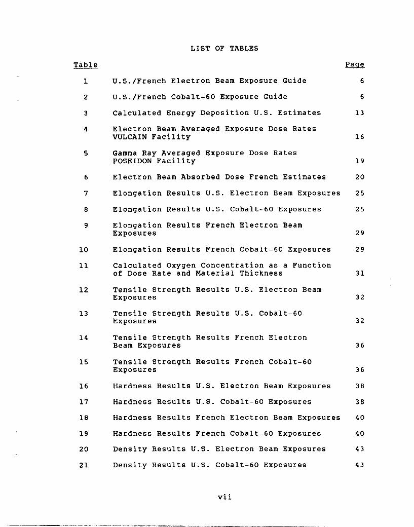
LIST OF TABLES
Table
1
2
3
4
5
6
7
8
9
10
11
12
13
14
15
16
17
18
19
20
21
U.S./French Electron Beam Exposure Guide
U.S./French Cobalt-60 Exposure Guide
Calculated Energy Deposition U.S. Estimates
Electron Beam Averaged Exposure Dose Rates W L C A I N Facility
Gamma Ray Averaged Exposure Dose Rates POSEIDON Facility
Electron Beam Absorbed Dose French Estimates
Elongation Results U.S. Electron Beam Exposures
Elongation Results U.S. Cobalt-60 Exposures
Elongation Results French Electron Beam Exposures
Elongation Results French Cobalt-60 Exposures
Calculated Oxygen Concentration as a Function of Dose Rate and Material Thickness
Tensile Strength Results U.S. Electron Beam Exposures
Tensile Strength Results U.S. Cobalt-60 Exposures
Tensile Strength Results French Electron Beam Exposures
Tensile Strength Results French Cobalt-60 Exposures
Hardness Results U.S. Electron Beam Exposures
Hardness Results U.S. Cobalt-60 Exposures
Hardness Results French Electron Beam Exposures
Hardness Results French Cobalt-60 Exposures
Density Results U.S. Electron Beam Exposures
Density Results U.S. Cobalt-60 Exposures
vi i
Paqe
6
6
13
16
19
20
25
25
29
29
31
32
32
36
36
38
38
40
40
43
43


EXECUTIVE SUMMARY
In order to determine the degree of equivalence, if any, that may exist between radiation damage to polymer base electrical insulation materials and type of irradiating environment, a joint cooperative research program to investigate the relative effectiveness of gamma and beta radiation to degrade such materials is currently in pro- gress. The ultimate aim of this program is to determine the adequacy of isotopic gamma irradiators, e.g., Cobalt-60 to simulate radiation damage in materials exposed to a loss of coolant accident (LOCA). The program is a multiyear, multiphase joint NRC/CEA effort.
The joint program consists of three parts:
1. Normalization
2. Gamma damage equivalence of beta radiation a. Screening tests b. Expanded tests
3 . Synergistic effects of mixed radiation fields.
Phase-1 has been completed and the results have been published.2 The object of Phase-1 was to establish cor- respondance between the two laboratories and that objective was accomplished.
The Phase-2 screening tests and data analysis have been completed and are the subject of this report. The purpose of Phase-2 was to investigate the relative effectiveness of electron and photon bombardments to produce damage in slab specimens of polymeric electrical insulation materials. Testing requirements, for this phase, were extensive. Re- quired were two material formulations and thicknesses, two integrated exposure doses, three exposure dose rates and two electron beam energies. In addition Cobalt-60 exposures, equivalent to the electron beam exposure doses and dose rates, were required for each material thickness. Since the radiation requirements were so extensive, the irradiations were divided between the U.S. and French laboratories.
The U.S. laboratory, Sandia National Laboratories (SNL), was responsible for the low energy electron beam exposures and the Cobalt-60 exposures of one sample thickness. High electron beam energy irradiations and Cobalt-60 exposure of the other thickness sample was the responsibility of the French laboratory, Laboratory of Biological Applications of Radiation (LABRA).
Radiation damage to the irradiated samples was based on changes in material properties. Parameters gauged were tensile properties, density, and hardness. Although the
uncertainty in some material response data is large, results of this test phase suggest that material damage resulting from electron beam and Cobalt-60 exposures may be correlated on the basis of absorbed dose determinations which in turn were estimated on the basis of measured exposure doses. For the material thicknesses considered here, measured Cobalt-60 exposure doses were always equivalent to calculated average absorbed doses. When electron beam exposures were consid- ered, however, measured exposure doses were rarely equiva- lent t o absorbed dose estimates. Although it cannot be stated unequivocally that electron and photon induced mate- rial damage may be equated on the basis of average absorbed dose independent of particle type, it is believed additional experimental data would strengthen this hypothesis. Specif- ically, the following investigations should be pursued. First, material response to at least one additional exposure dose obtained in the dose range of 300 kGy (30 Mrad) would be beneficial. Second, electron beam exposures should be expanded to include additional beam energies; say, for example, 0.3 and 0.8 MeV. And finally, response of insula- tion and jacket materials in cable (cylinder) geometry should be considered so that it may be verified that results obtained in slab geometry can be extended to cable (cylinder) configurations.
-2-
1.0 INTRODUCTION
This report is an account of the Phase-2 screening tests which are a segment of the joint French-American research program carried out under the auspices of the NRC ( U . S . ) and the CEA (France). The program was initiated to investigate the relative effectiveness of electron and photon bombard- ments to produce damage in polymer based rubber insulation materials used in nuclear reactor safety related items. The ultimate objective of this program is to determine the ade- quacy of isotopic gamma ray irradiators to realistically simulate radiation induced damage which is predicted to occur in polymer base electrical insulation materials exposed to the mixed .beta-gamma radiation field resulting from a nuclear reactor loss of coolant accident (LOCA). Research for this program in the U.S. was performed by Sandia National Laboratories (SNL) in Albuquerque, New Mexico and in France by the Laboratory of Biological Appli- cations of Radiation (LABRA) at the Saclay Nuclear Research Center in (Gif-Sur-Yvette), France.
LOCA radiation environments are complex. In addition to being comprised of both gamma and beta components, the emission rate and energy spectrum of each component is a varying function of time from release. Further, energy deposition in materials exposed to beta particle environ- ments is strongly dependent on particle energy and material thickness. And finally, polymer base material response may be sensitive to either/or both beta and/or gamma energy deposition rates. The Phase-2 screening tests were designed to address these concerns. Two polymer formulations in two thicknesses were exposed to two integrated exposure doses and three exposure dose rates of Cobalt-60 photons and two electron beam energies. lrradiated samples were then gauged for changes in tensile properties, hardness, and density. These data were then analyzed on the basis of measured doses and dose rates so that electron-photon equivalence could be investigated. The results of these Phase-2 screening tests are discussed. in detail, in the following sections.

2.0 BACKGROUND
Concern with beta-gamma equivalence is not without precedence. Calculations of LOCA radiation environments have in some cases1 predicted that the beta component is at least an order of magnitude greater than the photon component. Since it is not always feasible to eliminate this large beta component by means of shielding, various strategies have been employed to cope with simulation of the large beta component. Most frequently a one to one corre- spondence between beta and gamma irradiation effects on an exposure dose basis is assumed. This approach has disadvan- tages. The greatest may be that by invoking this procedure gross overexposure and attendant overstress of the test specimen may result. It is the purpose of this test phase to develop a method for simulating LOCA beta radiation environments with isotopic gamma simulators.
-4 -

3.0 TEST PROCEDURES
Phase-1 was intended primarily to establish CKOSS calibration between French and U.S. facilities by extensive interchange of dosimetry materials and (insulation) test specimens. On the other hand, for the Phase-2 program interchange of material was minimal. The primary purpose of this test phase was to investigate the equivalence between electron and photon induced damage in the selected electri- cal insulation materials. Composition and configuration of U.S. and French test specimens was identical to those tested in Phase-l.2
Extensive testing was performed during this phase. Common to both the U.S. and French programs were exposure dose rate and integrated exposure dose requirements. Two integrated exposure doses and three exposure dose rates were speci- fied. Material exposure doses of 150 and 500 kGy (15 and 5 0 Mrad) delivered at exposure dose rates of 0.8. 2.8, and 5 . 6 Gy 0 s-l (0.3, 1.0, and 2.0 Mrad hr-l) were specified for both electron and photon exposures. For electron beam exposures, both one and two millimeter (thick) test specimens were irradiated.
However, in the case of photon exposures, the French test specimens were two millimeters thick and the U.S. samples were one millimeter thick. As where indicated, interchange of test samples was minimal and consisted of an exchange of only two (150 mm by 150 mm) test sheets, one and two milli- meters thick, by each laboratory. The exchanged specimens were exposed in an electron beam environment to 150 and 500 kGy (15 and 50 Mrads) at an exposure dose rate of 5 . 6 Gy s-l (2.0 Mrad hr-l) and at the beam energy as- signed to the host laboratory. A guide for all of the electron beam irradiations is presented in Table 1 and for the Co-60 exposures in Table 2.
Entries scored with the asterisks indicate items interchanged between the two laboratories. Other entries are self explanatory. However, it should be pointed out that the dose/dose rate tabulations are in terms of exposure dose/dose rate and thus by U.S. convention dose/dose rate to air. On the other hand, French usage defines exposure dose/ dose rate on the basis of dose to air at the test sample surface. As noted U.S. electron beam energy was 0.5 MeV and the French beam energy was 1.0 MeV.
The electron energies cited above and in 'l'able 1 are averaged values. As explained in Reference 2, all irradia- tions were performed in air at ambient conditions. This required electron beam extraction, from the accelerator,

Table 1
U.S./French Electron Beam Exposure Guide
U.S. Samples French Samples Thickness Dose Dose Rate Energy MeV Energy MeV mm kGY Gy s-l
0.5 0.5 0.5 0.5 0.5 0.5 1.0" 1.0"
1.0 1.0 1.0 1.0 1.0 1.0 0 . 5 * * 0.5**
1 6 2 1 & 2 1 6 2 1 6 2 1 & 2 1 & 2 1 & 2 1 8 4 2
150 500 150 500 150 500 150 500
0.8 0.8 2.8 2.8 5.6 5.6 5.6 5.6
*U.S. samples exposed at the French WLCAIN facility **French samples exposed at the U.S. PELLETRON facility
Table 2
U.S./French Cobalt-60 Exposure Guide
U.S Samples Thickness mm
French Samples Thickness mm
Dose kGY
150 500 150 500 150 500
Dose Rate Gy s-l
0.8 0.8 2.8 2.8 5.6 5.6
-6-
and transport some distance, in air, to the target surface. Beam transport in air results in beam energy degradation and direction change. In Figure 1 are presented calculated electron spectra for electron beams incident at the target plane and after transport through intervening materials. These spectral estimates were calculated with the coupled electron-photon Monte Carlo transport code TIGER.3 The spectrum, on the left, is that estimated for the U.S. con- figuration and is the result of 0.63 MeV electron transport through the electron accelerator exit window and the inter- vening air gap separating the exit window and target plane. As may be observed, scattering in the window and air gap degraded the incident, monoenergetic beam, to a narrow spectrum of electrons with an average energy of approxi- mately 0 . 5 MeV. Thickness of the (beryllium) window was .005 cm and the air gap was 4 8 cm.
The TIGER approximation of the French electron spectrum is depicted by the right hand trace in Figure 1. Initial beam energy for this approximation was 1.0 MeV. The accelerator window was assumed to be .0027 cm titanium and the air gap was 39 cm. As may be observed, the electron spectrum incident at the target plane is sharply peaked at 0.85 MeV.
Degradation of irradiated test specimens was gauged on the basis of changes in mechanical/physical properties of the specimens. Both U.S. and French laboratories determined changes in tensile properties and hardness of the irradiated specimens. In addition, U.S. samples were checked for changes in material density. Both U.S. and French data were normalized on the basis of unirradiated material properties. Details of sample testing and sample analysis are described in Reference 2.
The ultimate objective of this program is to establish, if possible, a correlation between beta and gamma radiation induced damage in polymer base rubber insulation materials. Based on radiation dosimetry considerations, it appears feasible to examine the correlation between observed damage and energy absorbed from the incident beta/gamma radiation. Radiation dose/dose rate is generally cited on the basis of the intensity of exposure dose. In the U.S. exposure dose is generally construed to be energy absorption in air and is a measure of the intensity of a radiation environment. By French convention, in this report French exposure dose is on the basis of dose in air at the sample surface. When sample thicknesses on the order of those used in this program are exposed to energetic photons characteristic of Co-60 decay, absorbed dose is almost always adequately described by ex- posure dose. When considering electron beam exposures with beam energies specified for this program, exposure dose is seldom equivalent to absorbed dose. Energy deposition cal- culations predict exposure dose may over or under estimate

I
2
s
0
I 1
0%
Figure 1. Transmission Electron Spectra
-8-
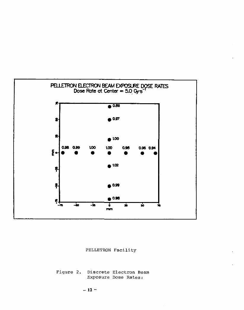
absorbed dose by 5 0 percent. Differences between absorbed and exposure doses of this magnitude suggest correspondence between exposure dose and beta/gamma equivalence is not likely to occur.
Accordingly, in this report all tabulated data such as that of Table 2, etc. are based on exposure dose. On the other hand, all graphical presentations are presented on the basis of absorbed dose.

4.0 IRRADIATION FACILITIES AND D0SI;METHY
The SNL and LABRA irradiation and dosimetry facilities were described in detail in Reference 2 and will only be reviewed briefly here.
4.1 Irradiation Facilities
4.1.1 U.S. Irradiation Facilities
Facilities at SNL consist of an electron beam accelerator, gamma irradiator, and a supporting laboratory. The electron beam accelerator, PELLETRON, is a nominal 1.0 MeV (maximum) machine that is characterized by both continuously variable current and voltage capabilities. Upper voltage limit is 1.15 MeV and maximum beam current is 3 4 microamps. Posi- tioned at the accelerator exit is a pair of orthogonal magnetic deflection coils whose function is to provide a uniform square pattern electron beam at the target plane.
The gamma irradiation facility consists of a dry irradiation cell positioned over a water source storage/shielding pool. This arrangement allows for access into the cell for test setup, adjustments, etc. When in use, a CO-60 array is raised from the pool and positioned in the irradiation cell. Two source configurations are available -- a planar array and a cylindrical configuration. Test specimens are placed external to the planar array for exposure dose rates up to 2 . 8 Gy s-l (1Mrad * hr-I). For higher dose rates the cylindrical array is required. By judicious selection of source number and positioning, dose rates on the order of 5 . 6 Gy s-l ( 2 Mrad hr-l) can be obtained in the interior of this array.
Laboratory support includes test specimen analysis equipment and dosimetry processing instruments.
4.1.2 French Irradiation Facilities
Compacable French facilities at LABRA include an electron beam accelerator, a Co-60 irradiator, and appropriate support laboratories.
The electron beam accelerator, W L C A I N , is a Van de Graaff machine with a voltage range between 0.5 and 3.0 MeV; beam current may be varied from a few microamps to one milliamp. After being accelerated, the beam is magnetically deflected in one direction before it is extracted into air. Air scatter is relied upon to deflect the beam in the other direction. Following magnetic deflection, the beam exits the accelerator through a .0027 cm titanium window and is then transported 39 cm in air to the target plane.
-10-

The gamma irradiation facility, (POSEIDON), has both planar and circular arrays. For lower than 1.2Gy.S-1 dose rate exposures, the planar array is preferred. This array is positioned on an elevator and is raised into a dry irradiation cell for sample exposures. Higher dose rate exposures are performed using the circular array, which is located on the POSEIDON pool base. Depending upon the dose rate required, the array can be configured with either three or eight source pencils. To use this source array test specimens and attendent support structure are positioned in a hermetically sealed and ventilated container which is then placed in the array center.
The usual support for dosimetry and materials test and analysis is also available.
4.2 Dosimetry
Both laboratories use thin film dosimetry materials to determine electron/gamma dose and dose rate. The U.S. used 15 cm by 15 cm polychlorostyrene sheets -005 cm thick. The dosimetry most often used at LABRA was triacetate (TAC) film 8 mm wide and 0.125 mm thick. In addition to TAC film the Metrology Laboratory of Ionizing Radiation (LMRI) at Saclay provided calibrated Alanine dosimeters.5'6
4.2.1 U.S. Dosimetry Results
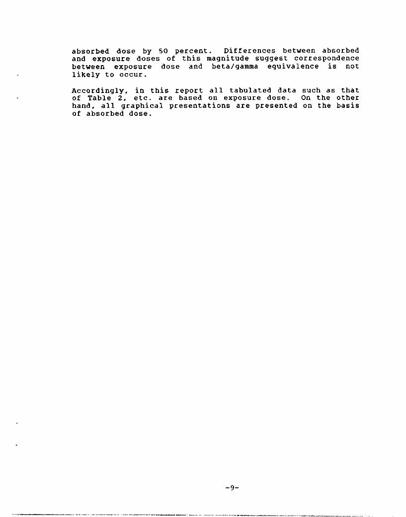
Prior to exposing any test samples, dosimetry was performed at both the electron beam and gamma irradiation facilities thus establishing radiation field uniformity and associated dose rate values. For electron beam exposures, a total stopping beryllium shutter was used to periodically inter- cept the electron beam incident on the target plane so that, during long exposure runs, it could be assured that beam conditioning was remaining constant. In addition, the relationship between intercepted (shutter) current and measured electron beam dose rate was established. Thus the inline shutter current monitor provided real time dose rate determinations. Measurement of dose to air with poly- chlorostyrene is known2 with an uncertainty of ten percent. Since the shutter current measurement uncertain- ties are much less than one percent, online dose rate determinations were also known with an uncertainty of ten percent. The electron beam dose rate distribution, in the target plane, as determined with a 15 by 15 cm sheet of polychlorostyrene dosimetry material is depicted in Figure 2 . The figure depicts dose rate distribution values along the vertical and horizontal electron beam axes at the target plane. Dimension of numbers defining coordinates of dose rate values in the target plane are in units of millimeters. Dose rate values have been normalized on the basis of the
pELLETRoNELEmBEAMD(posuREDosE:RATEs Dose Rate at Center = 5.0, Gys-'
#
a 0 0 3 7
PELLETRON Faci l i ty
Figure 2. Discrete Electron Beam Exposure Dose Rates :
- 12 -
center line dose rate value. As may be observed the beam is quite uniform at the target plane with a maximum to minimum variation in dose rate along the centerlines of 11 percent.
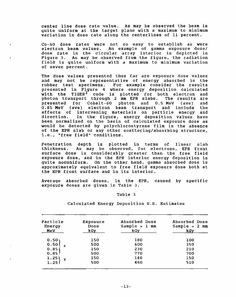
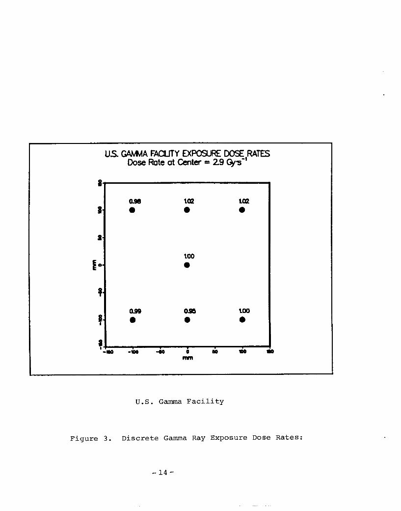
CO-60 dose rates were not so easy to establish as were electron beam values. An example of gamma exposure dose/ dose rate in the circular array interior is depicted in Figure 3. As may be observed from the figure, the radiation field is quite uniform with a maximum to minimum variation of seven percent.
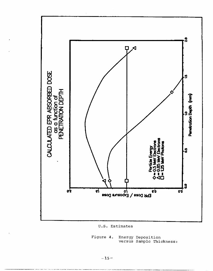
The dose values presented thus far are exposure dose values and may not be representative of energy absorbed in the rubber test specimens,. For example consider the results presented in Figure 4 where energy deposition calculated with the TIGER3 code is plotted for both electron and photon transport through 2 mm EPR slabs. The results are presented for Cobalt-60 photon and 0.5 MeV (ave) and 0 . 8 5 MeV (ave) electron beam transport and include the effects of intervening materials on particle energy and direction. In the figure, energy deposition values have been normalized on the basis of calculated exposure dose as would be detected by polychlorostyrene film in the absence of the EPR slab or any other scattering/absorbing structure, i.e., "free field" conditions.
Penetration depth is plotted in terms of linear slab thickness. As may be observed, for electrons, EPR front surface dose is considerably greater than the free field exposure dose, and in the EPR interior energy deposition is quite nonuniform. On the other hand, gamma absorbed dose is approximately equivalent to free field exposure dose both at the EPR front surface and in its interior.
Average absorbed doses, in the EPR. caused by specific exposure doses are given in Table 3.
Table 3
Calculated Energy Deposition U.S. Estimates
Particle Energy MeV
Exposure Dose kGy
150 500 150 500 150 500
Absorbed Dose Sample = 1 mm
kGy
180 600 230 770 140 460
Absorbed Dose Sample = 2 mm
kGy
100 350 210 700 150 510
too e
OSB e
U . S . Gamma F a c i l i t y
F i g u r e 3. D i s c r e t e Gamma R a y Exposure D o s e R a t e s :
- 14 -
c ro 0
U . S . E s t i m a t e s
F igure 4 . Energy Depos i t ion ve r sus Sample Thickness:

In the table are listed average absorbed dose values, for both 1 and 2 mm EPR, resulting from several exposure doses. As may be observed, except for Cobalt-60, exposure dose is a poor indicator of absorbed dose. In what follows, U.S. radiation damage data plots will be presented as a function the absorbed dose values given in Table 3 .
4.2.2 French Dosimetry Results
French electron beam and gamma dosimetry measurements were obtained prior to any test specimen exposures. Both cellu- lose triacetate (TAC) and alanine dosimeters were used for electron beam measurements. Electron beam dose rate mapping measurements were obtained by placing TAC strips on the polyethelene sample support plate which was positioned at the appropriate location in the electron beam. For discrete electron beam and gamma dose determinations, 0.2-mm thick alanine dosimeters were used. The dosimeters were placed in 0.2-mm grooves machined in the polyethelene support plate. Measurements obtained by either technique yield dose to air at the surface of the support place. Uncertainties in dose rates obtained by these techniques were approximately 14 percent for electron beam measurements and about seven percent for comparable gamma ray dose rate determinations. Representative, discrete electron beam dose rate data, obtained with alanine dosimetry, are presented in Figure 5; units of dose rate point coordinates are millimeters. Com- parable isodose rate data, obtained with TAC dosimetry, are given in Figure 6. As may be observed agreement between the two dosimeters is good. Average dose rate gradient across the electron beam is about seven percent. Condensed elec- tron beam dose rate data are listed in Table 4 . Presented, in Table 4 , are exposure data for the three dose rates used in the French exposures and also for the U.S. samples irradiated at WLCAIN.
Table 4
Electron Beam Averaged Exposure Dose Rates VULCAIN Facility
Dose Rate* Dose Rate Gradient Gy s-l Gy
0.86 2.71 5.72 5.50**
0.08 0.20 0.36 0.47
*EfrOr for each measurement point is 215 percent **Average dose rate for U.S. samples exposured at WLCAIN
-16-

V W ELECTRON BEAM EXPOSURE DOSE R A . . Dose Rate at Center = 6.1 Gps-'
0.89 0.97 e 0.90
0.92 D 0
0.93 D 0.86 0
0.92 D 0.82 e
0.97 0
LOO 0
096 e
O"' 0.83 e
0.93 0.86
0.92 e 0
0.91 0.95 0.89 I I I I I
mm
VULCAIN F a c i l i t y
F igure 5. Discrete E l e c t r o n B e a m Exposure D o s e R a t e s :

W L C A I N F a c i l i t y
F i g u r e 6 . Isodose R a t e Curves:
- 18-
Data presented are the dose rate averaged over the electron beam and the companion dose rate gradient for each measured exposure dose rate.
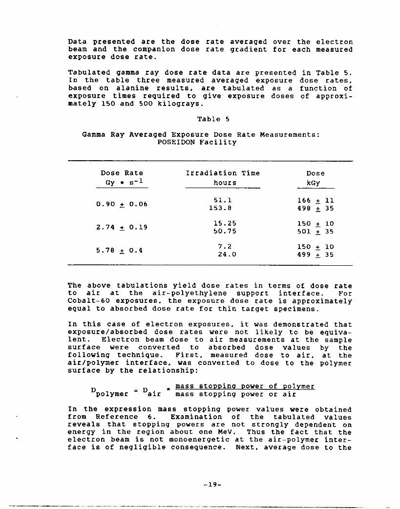
Tabulated gamma ray dose rate data are presented in Table 5. In the table three measured averaged exposure dose rates, based on alanine results, are tabulated as a function of exposure times required to give exposure doses of approxi- mately 150 and 500 kilograys.
Table 5
Gamma Ray Averaged Exposure Dose Rate Measurements: POSEIDON Facility
Dose Rate Irradiation Time Dose Gy s-1 hours kGY
0.90 t 0.06
2.74 0.19
5.70 2 0.4
51.1 153.8
15.25 50.75
7.2 24.0
166 & 11 498 35
150 +. 10 501 A 35
150 +. 10 499 & 35
The above tabulations yield dose rates in terms of dose rate to air at the air-polyethylene support interface. For Cobalt-60 exposures, the exposure dose rate is approximately equal to absorbed dose rate for thin target specimens.
In this case of electron exposures, it was demonstrated that exposure/absorbed dose rates were not likely to be equiva- lent. Electron beam dose to air measurements at the sample surface were converted to absorbed dose values by the following technique. First, measured dose to air, at the air/polymer interface, was converted to dose to the polymer surface by the relationship:
- r* mass stopping power of polymer 'polymer - 'air mass stopping power or air
In the expression mass stopping power values were obtained from Reference 6. Examination of the tabulated values reveals that stopping powers are not strongly dependent on energy in the region about one MeV. Thus the fact that the electron beam is not monoenergetic at the air-polymer inter- face is of negligible consequence. Next, average dose to the
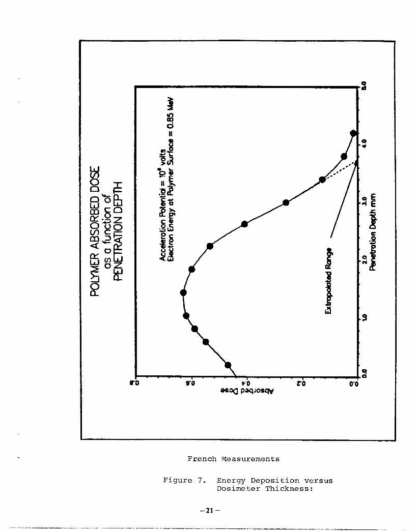
polymer interior was estimated by means of an experimentally determined energy deposition curve obtained with an infinite stack (to the incident electron beam) of 0.2 mm alanine dosimeters. It is of interest t o note that the extrapolated electron range determined from Figure 7 corresponds to a 0.85 MeV average electron energy. Area under the deposition curve (Figure 7 ) was estimated for both 1 and 2 mm beam penetration depths. Average energy deposition, for each penetration depth, was then estimated, in the usual way, as depicted by the following integral presentation:
fdE/dx * dx dE/dX =
sax
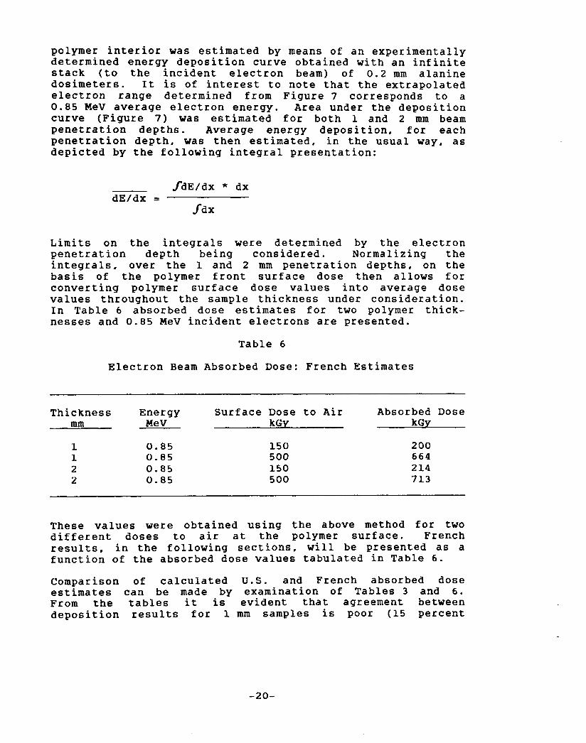
Limits on the integrals were determined by the electron penetration depth being considered. Normalizing the integrals, over the 1 and 2 mm penetration depths, on the basis of the polymer front surface dose then allows for converting polymer surface dose values into average dose values throughout the sample thickness under consideration. In Table 6 absorbed dose estimates for two polymer thick- nesses and 0.85 MeV incident electrons are presented.
Table 6
Electron Beam Absorbed Dose: French Estimates
Thickness Energy Surface Dose to Air Absorbed Dose mm MeV kGy kGy
I 0 . 8 5 1 0 . 8 5 2 0.85 2 0.85
150 500 150 500
200 6 6 4 2 14 713
These values were obtained using the above method for two different doses to air at the polymer surface. French results, in the following sections, will be presented as a function of the absorbed dose values tabulated in Table 6 .
Comparison of calculated U . S . and French absorbed dose estimates can be made by examination of Tables 3 and 6. From the tables it is evident that agreement between deposition results for 1 mm samples is poor (15 percent
-20-
. . . . . t b a
French Measurements
F igu re 7. Energy Depos i t ion ve r sus D o s i m e t e r Thickness:
- 2 1 -
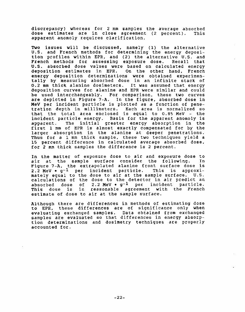
discrepancy) whereas for 2 mm samples the average absorbed dose estimates are in close agreement (2 percent). This apparent anomoly requires clarification.
Two issues will be discussed, namely (1) the alternative U.S. and French methods for determining the energy deposi- tion profiles within EPR, and (2) the alternative U.S. and French methods for assessing exposure dose. Recall that U.S. absorbed dose values were based on calculated energy deposition estimates in EPR. On the other hand, French energy deposition determinations were obtained experimen- tally by measuring absorbed dose in an infinite stack of 0 . 2 mm thick alanine dosimeters. It was assumed that energy deposition curves for. alanine and EPR were similar and could be used interchangeably. For comparison, these two curves are depicted in Figure 7 - A . In the figure, absorbed dose in MeV per incident particle is plotted as a function of pene- tration depth in millimeters. Each area is normalized s o that the total area enclosed is equal to 0 . 8 5 MeV - the incident particle energy. Basis for the apparent anomoly is apparent. The initial greater energy absorption in the first 1 mm of EPR is almost exactly compensated for by the larger absorption in the alanine at deeper penetrations. Thus for a 1 mm thick sample, these two techniques yield a 15 percent difference in calculated average absorbed dose, for 2 mm thick samples the difference is 2 percent.
In the matter of exposure dose to air and exposure dose to air at the sample surface consider the following. In Figure 7-A , the extrapolated alanine front surface dose is 2.2 MeV 9-1 per incident particle. This is approxi- mately equal to the dose to air at the sample surface. U.S. calculations of the dose to the detector in air predict an absorbed dose of 2.2 MeV g-l per incident particle. This dose is in reasonable agreement with the French estimate of dose to air at the sample surface.
Although there are differences in methods of estimating dose to EPR, these differences are of significance only when evaluating exchanged samples. Data obtained from exchanged samples are evaluated so that differences in energy absorp- tion determinations and dosimetry techniques are properly accounted for.
-22-
z H n
3 8 I
0
U.S. and French R e s u l t s
F igure 7-A. E l e c t r o n Energy Deposi t ion ve r sus Sample Thickness:
- 23 -
5 . RESULTS
Material response to electron and gamma exposures was based on changes in mechanical properties. Properties monitored were elongation at break, ultimate tensile strength, hard- ness, and density. All property changes were referenced to unirradiated material values. In all instances response data were plotted as a function of absorbed dose. U.S. absorbed dose values were based on "free fieldii exposure dose to air determinations. French absorbed dose values were referenced to exposure dose to air at the sample surface.
5.1 Elonqation
5.1.1 U . S . Results
Elongation results for the electron beam irradiations are presented in Table 7 for all material thicknesses, inte- grated doses, and dose rates. Comparable data for the CO-60 exposures are tabulated in Table 8 .
All entries in the compilation are self-explanatory, however, it should be pointed out again that the dose and dose rate columns are in terms of exposure values. Each elongation result is the mean value of five to ten elonga- tion measurements. The uncertainty associated with each elongation result in calculated as the standard deviation with respect to the mean value.
The elongation data presented in the tables are plotted in Figure 8 as a function of (average) absorbed dose. In the plot, the solid curve through the data points is an esti- mated best fit to the data. With the exception of the one MeV electron exposure (at 150 kGy exposure dose), the data are reasonably well representated by the solid curve approxlmation to the data points.
The data of Figure 8 have not been adjusted for dose rate effects. Dose rate effects on observed material elongation are presented in Figure 9 . Electron beam data are given in the left plot and photon data in the right hand plot; solid curves in each plot are best estimate fits to the data. From the electron beam data it is observed that dose rate response is integrated dose dependent in that a dose rate dependence is observed for the 150 kGy exposures and virtually no observed rate dependence for the 500 kGy exposures. Change in elongation, attributable to dose rate effects, is estimated from the data to be on the order of about plus or minus 10 percent.
-24 -
Table 7
Elongation Results U.S. Electron Beam Exposures
Energy Thickness Exposure Dose Normalized Elongation MeV mm kGY Gy s - l E/Eo
1 . O * 1 . O * 0.5 0.5 0.5 0.5 0.5 0.5 1.0" 1.0" 0.5 0.5 0.5 0.5 0.5
2 2 2 2 2 2 2 2 1 1 1 1 1 1 1
150 500 150 150 150 500 500 500 150 500 150 150 150 500 500
5.6 5.6 0 . 8 2.8 5.6 0.8 2.8 5.6 5.6 5.6 0.8 2.8 5.6 2.8 5.6
*Samples exposed to 1.0 MeV beam at W L C A I N
0.36 2 0.03 0.23 2 0.03 0.45 2 0.06 0.51 2 0.10 0.47 2 0.08 0.26 2 0.03 0.23 2 0.08 0.24 2 0.05 0.63 2 0.05 0.30 2 0.03 0.38 0.05 0.52 0.05 0.56 2 0.07 0.23 2 0.02 0.21 2 0.03
Table 8
Elongation Results U.S. Cobalt-60 Exposures
Thickness mm
Exposure Dose kGY Gy s-l
Normalized Elongation E/Eo
150 0 . 8 150 2.8 150 5.6 500 0 . 8 500 2.8 500 5.6
0.46 2 0.08 0.48 2 0.05 0.53 2 0.05 0.23 2 0.02 0.14 2 0.03 0.21 2 0.03

U.S. Resu l t s
F igure 8. E longat ion as a f u n c t i o n of Absorbed D o s e :
-26-

0 rd
, I l I
U.S. R e s u l t s
F igure 9 . E l o n g a t i o n as a f u n c t i o n of Absorbed Dose R a t e :
The Co-60 rate data are the reverse of those observed for electron beam exposures in that rate effects were detected for the 500 kGy exposures. Elongation changes attributable to rate effects are approximately 15 percent.
When plotted as a function of absorbed dose, elongation data obtained from electron beam and Co-60 exposures track one another reasonably well even though uncertainties in the experimental data are rather large. This observed trend is consistent with the results reported in Reference 7.
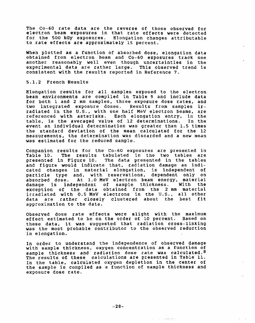
5.1.2 French Results
Elongation results for all samples exposed to the electron beam environments are compiled in Table 9 and include data for both 1 and 2 mm samples, three exposure dose rates, and two integrated exposure doses. Results from samples ir- radiated in the U.S., with one half MeV electron beams, are referenced with asterisks. Each elongation entry, in the table, is the averaged value of 12 determinations. In the event an individual determination was greater than 1.5 times the standard deviation of the mean calculated for the 12 measurements, the determination was discarded and a new mean was estimated for the reduced sample.
Companion results for the Co-60 exposures are presented in Table 10. The results tabulated in the two tables are presented in Figure 10. The data presented in the tables and figure would indicate that, radiation damage as indi- cated changes in material elongation, is independent of particle type and, with reservations, dependent only on absorbed dose. At 1.0 MeV electron beam energy, material damage is independent of sample thickness. With the exception of the data obtained from the 2 mm material irradiated with 0 . 5 MeV electrons in the U.S., all other data are rather closely clustered about the best fit approximation to the data.
Observed dose rate effects were slight with the maximum effect estimated to be on the order of 10 percent. Based on these data, it was suggested that radiation cross-linking was the most probable contributor to the observed reduction in elongation.
In order to understand the independence of observed damage with sample thickness, oxygen concentration as a function of sample thickness and radiation dose rate was calculated.8 The results of these calculations are presented in Table 11. In the table, calculated oxygen depletion in the center of the sample is compiled as a function of sample thickness and exposure dose rate.
-28-
Table 9
Elongation Results French Electron Beam Exposures
Energy Thickness Exposure Dose Normalized Elongation MeV mm kGY Gy 8 s-l E/Eo
0.5* 0.5* 1.0 1.0 1.0 1.0 1.0 1.0 0.5* 0.5" 1.0 1.0 1.0 1.0 1.0 1.0
2 2 2 2 2 2 2 2 1 1 1 1 1 1 1 1
150 500 150 150 150 500 500 500 150 500 150 150 150 500 500 500
5.6 5.6 0.8 2.8 5.6 0.8 2.8 5.6 5.6 5.6 0.8 2.8 5.6 0.8 2.8 5.6
*Samples exposed to 0.5 MeV beam at PELLETRON
0.781 0.530 0.907 0.803 0.896 0.570 0.616 0.620 0.838 0.463 0.801 0.868 0.780 0.581 0.568 0.520
Table 10
Elongation Results French Cobalt-60 Exposures
Thickness mm
Exposure Dose kGY Gy 8 s-l
Normalized Elongation E/Eo
150 0.8 150 2.8 150 5.6 500 0.8 500 2.8 500 5.6
0.950 1.018 0.953 0.653 0.710 0.753

X
0
French R e s u l t s
F i g u r e 9. E longa t ion as a f u n c t i o n of Absorbed D o s e R a t e :
-30-

Table 11
Calculated Oxygen Concentration as a Function of
Dose Rate and Material Thickness
Dose Rate Gy S-l 0.8 2.8 5.6
Thickness mm O2 Concentration
O + b 1 2
0.00081 0.00081 0.00081 0.00079 0.00076 0.00074 0.00075 0.00067 0.00059
From the table it is noted that maximum oxygen depletion occurs in the 2 mm material and for a dose rate of 5.6 Gy sec-I (2 Mrad hr-1). For steady state diffusion, the oxygen concentration is reduced from 8 0 1 0 - 4 to 5.9 1 0 - 4 cm3 of oxygen, at STP, per cc of EPR per cm Hg of atmospheric pressure. It is not considered likely that this level of oxygen depletion would perturb the rate of polymer degradation from molecular cross-linking.
5.2 Tensile Strenqth
5.2.1 U.S. Results
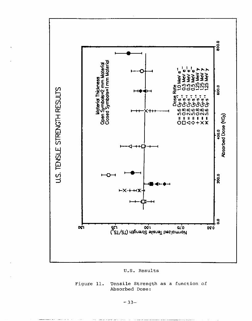
Tensile strength data, from electron beam and Co-60 exposures, were obtained concurrently with elongation data. The electron beam and Co-60 results are compiled in Tables 12 and 13, respectively, as a function of exposure dose. Entries, referenced with asterisks, denote samples that were irradiated in France with 1.0 MeV electron beams and re- turned to the U.S. for evaluation. All data have been normalized to the unirradiated tensile strength value.
The tensile strength data are presented in Figure 11 as a function of absorbed dose. From the plot, it may be observed that tensile strength is a slowly varying function of absorbed dose. Although the data spread is rather large, it may be inferred that for this material tensile strength increases slightly with increasing absorbed dose and is independent of exposure type.
Dose rate effects on material response are plotted in Figure 12. Electron beam dose rates are plotted in the left figure and Co-60 results in the right figure. Observed
Table 12
Tensile Strength Results U . S . Electron Beam Exposures
Energy Thickness Exposure Dose Normalized Tensile Strength MeV mm kGY Gy s-l T/To
1.0* 1.0* 0.5 0.5 0.5 0.5 0.5 0.5 1.0* 1.O* 0.5 0.5 0.5 0.5 0.5
2 150 2 500 2 150 2 150 2 150 2 500 2 500 2 500 1 150 1 500 1 150 1 150 1 150 1 500 1 500
5.6 5.6 0.8 2.8 5.6 0.8 2.8 5.6 5.6 5.6 0.8 2.8 5.6 2.8 5.6
*Samples exposed to 1 MeV beam at W L C A I N
1.30 fi 0.05 1.05 fi 0.08 1.04 k 0.06 1.03 2 0.07 1.05 fi 0.09 1.04 fi 0.05 1.14 fi 0.07 1 . 0 3 2 0.03 1.12 0.06 1.15 0.10 0.98 k 0.05 0.94 fi 0.06 0.88 2 0.04 1.03 2 0.05 1.06 0.95
Table 13
Tensile Strength Results U.S. Cobalt-60 Exposures
Thickness Exposure dose Normalized Tensile Strength mm kGY Gy s-l T/To
150 0.8 150 2.8 150 5.6 500 0.8 500 2.8 500 5.6
1.07 fi 0.04 1.34 t 0.08 1.18 fi 0.04 1.06 2 0.05 0.99 2 0.14 1.02 2 0.07
-32-
vi 5
0
U.S . Resu l t s
F igure 11. T e n s i l e S t r e n g t h as a func t ion of Absorbed D o s e :
- 33-

I . - . . I . . . . , . _ . .
m cn 001 K'o csl/si, W S rl-1 PnPUJJw
' T I /j
U.S. Resu l t s
F igure 1 2 . Tens i l e S t r e n g t h as a f u n c t i o n of Absorbed Dose R a t e :
- 3 4 -

electron beam rate effects are small - on the order of 6 percent. On the other hand, gamma rate effects are large and on the order of 13 percent. Because of the large uncer- tainties associated with the tensile strength data, these results are somewhat suspect.
5 . 2 . 2 French Results
Tensile strength results are compiled in Tables 14 and 15 for electron beam and Co-60 exposures. Entries referenced with asterisks identify samples irradiated in the U.S. and returned to France for evaluation. All tensile strength results are plotted in Figure 13. Graphed is normalized tensile strength as a function of absorbed dose. Based on the data presented and as was observed from the elongation results, no effects attributable to material thickness were observed with the possible exception those data obtained from 2 mm material exposed to 0.5 MeV electrons.
Observed dose rate effects were small - on the order of 10 percent or less. A possible anomoly exists with the 1.0 MeV data obtained at a dose rate of 0.8 Gy s-1 (0.3 Mrad hr-l) and that may be attributable to dose rate effects. Based on the above, it is concluded that there is no significant difference in electron beam and Cobalt-60 radiation effects.
5.3 Hardness
Techniques for determining hardness were presented in Reference 2. All hardness measurements, presented here, are based on the Shore A scale which gauges material hardness on the basis elastic rebound.
5.3.1 U.S. Results
Hardness data for electron beam and Co-60 exposures are tabulated in Tables 16 and 17 respectively. These data are plotted as a function of absorbed dose in Figure 14. Examination of the data would predict that hardness is insensitive to absorbed dose and dose rate.
5.3.2 French Results
Hardness data are compiled in Tables 18 (electron beam exposures) and 19 (Co-60 exposures). These data are plotted in Figure 15. These data suggest hardness measurements are not sensitive enough to detect any change in hardness.

Table 14
Tensile Strength Results French Electron Beam Exposures
Energy Thickness Exposure Dose Normalized Tensile Strength MeV mm kGY Gy 8 s-l T/To
0.5* o.s* 1.0 1.0 1.0 1.0 1.0 1.0 0.5* O . S * 1.0 1.0 1.0 1.0 1.0 1.0
2 2 2 2 2 2 2 2 1 1 1 1 1 1 1 1
150 500 150 150 150 500 500 500 150 500 150 150 150 500 500 500
5.6 5.6 0.8 2.8 5.6 0.8 2.8 5.6 5.6 5.6 0.8 2.8 5.6 0.8 2.8 5.6
*Samples exposed to 0.5 MeV beam at
0.867 0.547 0.940 0.927 0.967 0.607 0.680 0.753 0.908 0.632 0.862 0.921 0.579 0.487 0.697 0.579
PELLETHON
Table 15
Tensile Strength Results French Cobalt-60 Exposures
Thickness Exposure Dose Normalized Tensile Strength mm kGY GY S-1 T/T,
150 0.8 150 2.8 150 5.6 500 0.8 500 2.8 500 5.6
0.980 0.920 0.880 0.653 0.667 0.713
-36-

0
French R e s u l t s
F igu re 13. T e n s i l e S t r e n g t h as a f u n c t i o n of Absorbed Dose:
- 37-
. . . ..I._ ..._ ^ . _ _ , .. ._ . . ~.~ , . ,

Table 16
Hardness Results U.S. Electron Beam Exposures
Energy Thickness Exposure Dose Normalized Hardness MeV mm k G Y G y s - l H/H,
1.0* 1.0" 0.5 0.5 0.5 0.5 0.5 0.5 1.0* 1.0* 0.5 0.5 0.5 0.5 0.5
2 2 2 2 2 2 2 2 1 1 1 1 1 1 1
150 500 150 150 150 500 500 500 150 500 150 150 150 500 500
5.6 5.6 0.8 2.8 5.6 0.8 2.8 5.6 5.6 5.6 0.8 2.8 5.6 2.8 5.6
*Samples exposed to 1.0 MeV beam at W L C A I N
1.03 2 0.02 1.05 t 0.04 1.03 2 0.03 1.04 2 0.02
0.73 2 0.05 0.97 2 0.07 1.04 2 0.02 1.05 +. 0.02 1.06 2 0.02 0.97 2 0.06 1.04 2 0.01 1.04 2 0.02 1.07 2 0.01 1.07 2 0.01
1.02 2 0.02
Table 17
Hardness Results U . S . Cobalt-60 Exposures
Thickness mm
Exposure Dose k G Y Gy s-l
Normalized Hardness H/Ho
150 0.8 150 2.8 150 5.6 500 0.8 500 2.8 500 5.6
1.03 & 0.02
1.03 2 0.02
1.00 2 0.03 1.03 2 0.02
1.02 2 0.02
1.01 & 0.02
-38-

U.S. Results
Figure 14. Hardness as a function of Absorbed Dose:
- 39-
.... . . . ., . . , . .. . . ~ - - .. . ._ ... ". . ._
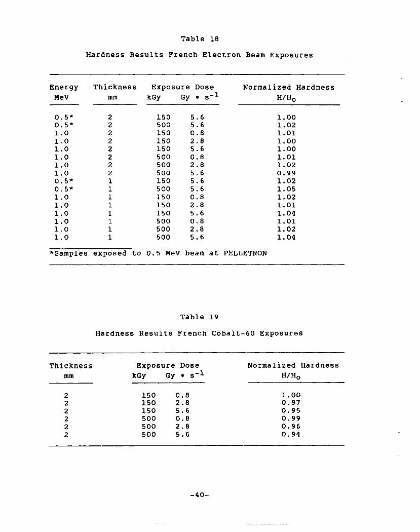
Table 18
Hardness Results French Electron Beam Exposures
Energy MeV
Thickness mm
Exposure Dose kGY Gy s-l
Normalized Hardness H/Ho
0.5" 0.5" 1.0 1.0 1.0 1.0 1.0 1.0 0.5* 0.5" 1.0 1.0 1.0 1.0 1.0 1.0
2 2 2 2 2 2 2 2 1 1 1 1 1 1 1 1
150 5.6 500 5.6 150 0.8 150 2.8 150 5.6 500 0.8 500 2.8 500 5.6 150 5.6 500 5.6 150 0.8 150 2.8 150 5.6 500 0.8 500 2.8 500 5.6
*Samples exposed to 0.5 MeV beam at PELLETRON
1.00 1.02 1.01 1.00 1.00 1.01 1.02 0.99 1.02 1.05 1.02 1.01 1.04 1.01 1.02 1.04
Table 19
Hardness Results French Cobalt-60 Exposures
Thickness Exposure Dose Normalized Hardness mm kGY Gy s-l H/Ho
150 0.8 150 2.8 150 5.6 500 0.8 500 2.8 500 5.6
1.00 0.97 0.95 0.99 0.96 0.94
-40 -
Y
% 0 0
II II I1 II II II II ooao+xx
French Results
Figure 15. Hardness as a function of Absorbed Dose:
-41-

5.4 Density
5.4.1 U.S. Results
Tabulated density data for electron beam and CO-60 exposures are presented in Tables 20 and 21 as a function of exposure dose. In Figure 16 these data are plotted as a function of absorbed dose. Examination of the data indicates that any changes in density that may have occurred are too small to detect.
-42-
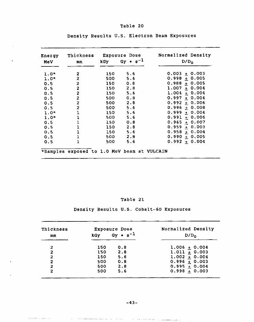
Table 20
Density Results U.S. Electron Beam Exposures
Energy Thickness Exposure Dose Normalized Density MeV mm kGY Gy s-l D/Do
1.0" 1.0" 0.5 0.5 0.5 0.5 0.5 0.5 1.0" 1.0* 0.5 0.5 0.5 0.5 0.5
2 2 2 2 2 2 2 2 1 1 1 1 1 1 1
150 5.6 500 5.6 150 0.8 150 2.8 150 5.6 500 0.8 500 2.8 500 5.6 150 5.6 500 5.6 150 0.8 150 2.8 150 5.6 500 2.8 500 5.6
0.003 t; 0.003 0.998 t; 0.005 0.988 +- 0.005 1.007 t; 0.004 1.004 t; 0.004 0.997 2 0.004 0.992 +- 0.006 0.996 2 0.008 0.999 2 0.004 0.991 2 0.006 0.965 2 0.007 0.959 2 0.003 0.958 2 0.004 0.990 t; 0.005 0.992 2 0.004
*Samples exposed to 1.0 MeV beam at W L C A I N
Table 21
Density Results U.S. Cobalt-60 Exposures
Thickness mm
Exposure Dose kGY Gy s-l
Normalized Density D/Do
150 0.8 150 2.8 150 5.6 500 0.8 500 2.8 500 5.6
1.006 2 0.004 1.011 2 0.003 1.002 2 0.004 0.996 2 0.003 0.995 5 0.004 0.998 0.003
-43-
--- ". -- - I .̂
c
C
I
U.S. Resu l t s
F igure 1 6 . Dens i ty as a func t ion of Absorbed D o s e :
-44-

6.0 DISCUSSION AND CONCLUSIONS
The relative effectiveness of gamma photons and beta particles to produce damage in polymer base rubber electri- cal insulation materials has been investigated. Using Co-60 gammas and accelerator produced electron beams, relative damage in two EPR rubber formulations has been studied. The multiparameter investigation examined damage as a function of electron beam energy, dose, dose rate, and sample thick- ness. Companion to the electron beam exposures, material response to Co-60 exposures as a function dose, dose rate, and material thickness was also investigated. Material response or damage was equated to changes in material prop- erties. Properties monitored were elongation at break, ultimate tensile strength, Shore hardness, and density. Changes in material properties were then equated to the radiation environments. Effectiveness and equivalence of the radiation environments (Cobalt-60 and electron beam) were gauged on the basis of observed material damage and calculated/measured average dose deposited in the exposed specimens.
Analysis of the irradiated test specimens demonstrated that material hardness and density were small or unchanged at the exposure doses used in this study. On the other hand, both elongation and tensile strength were responsive to electron beam and Cobalt-60 irradiations. In addition, elongation and tensile strength measurements exhibited a measurable, although small, dose rate dependence. For samples irradi- ated with 1.0 MeV electrons and Co-60 photons, no dependence of response on sample thickness was observed. In the case of 0 . 5 MeV electron beam exposures, apparent thickness dependent response was resolved when the response was equated to absorbed dose rather than exposure dose.
Some evidence of electron beam energy dependent material response was observed; however, it has not been resolved whether the effect is the result of experimental error.
Beta/gamma equivalence was tested on the basis of equating observed electron beam and Cobalt-60 radiation damage, in test specimens, to estimated absorbed dose in the exposed samples. When absorbed dose was used as the independent variable, electron beam and Cobalt-60 radiation damage, as indicated by changes in test specimen tensile properties, was in agreement and tracked with absorbed dose in a pre- dictable manner. This correspondence leads to the tentative conclusion that equivalence between Cobalt-60 and electron beam exposures exists. Equivalence may not be apparent if reliance is placed solely on exposure dose as a gauge of radiation dose to materials.
Before drawing a definite conclusion as to the correctness of beta/gamma equivalence, further investigations would be helpful. Additional radiation exposure doses, intermediate to those used in this study, should be used e.g., in the region about 300 kGy (30 Mrad). The range of electron energies should be increased to include 0.3 and 0.8 MeV. And finally, cylinder (cable) geometry composed of both jacket and insulation formulations should be investigated.
-46-
REFERENCES
1.
2 .
3.
4.
5.
6.
7 .
8 .
L. L. Bonzon and N. A. Lurie, Best-Estimate LOCA Radiation Signature, NUREG/CR-1237. SAND79-2143, Sandia National Laboratories, Albuquerque, New Mexico, January 1980.
F. J. Wyant, W. H. Buckalew, J. Chenion, F. Carlin, G. Gaussens, P. Le Tutour, and M. Le Meur, U.S./French Joint Research Proqram Reqardina the Behavior of Polymer Base Materials Subjected to Beta Radiation, Volume 1: Phase-1 Normalization Results, NUREG/CR-4530/1 of 1, SAND86-0366/1 of 4, Sandia National Laboratories, Albuquerque, New Mexico, June 1986.
J. A. Halbleib and W. H. Vandevender, Nuc. Sci. Enq., 5 7 , 94 (1975)
D. Mosse, M. Cance, and J. P. Sirnoen, French Proqram in Reference Dosimetry for Ionizinq Radiation Processing of -8 Food IAEA, SM 271, Food Irradiation Processing Symposium, Washington, D.C., March 4 to 8, 1985, IAEA, F. A. O., 1985.
D. Mosse, Alanine ESR Dosimetry at the LMRI Applied Irradiation Processinq, 6th International Meeting of Radiation Processing, Ottawa, Canada, To be published.
I. C. R. U. Report 57, StoPPinq Powers for Electrons and Positrons, October 1984.
W. H. Buckalew, First Results from Electron-Photon Damage Equivalence Studies on a Generic Ethvlene-Propvlene Rubber, NUREG/CR-4543, SAND86-0462, Sandia National Laboratories, Albuquerque, New Mexico, April 1986.
J. Berthet, G. Gaussens, L. Laizer, and F. Lemaire, Qualification Nucl'eaire des Plastiques, Caoutchouc et Plastiques No. 56, June/July 1978.
-4 7-

DISTRIBUTION:
U.S. Government Printing Office Receiving Branch (Attn: EJRC Stock) 8610 Cherry Lane Laurel, HD 20707 330 copies for RV
.Ansaldo Impianti Centro Sperimentale del Boschetto Corso F.W. Perrone, 118 16161 Genova ITALY Attn: C. Bozzolo
Ansaldo Impianti Via Gabriele D'Annunzio, 113 16121 Genova ITALY Attn: S. Grifoni
ASEA-ATOM Department KRD Box 53
Vasteras SWEDEN Attn: A. Kjellberg
S-721 04
ASEA-ATOM Department TQD Box 53
Vas te ras SWEDEN Attn: T. Granberg
S-721 04
ASEA KAEIEL AB P.O. Box 42 108
Stockholm SWEDEN Attn: B. Dellby
S-126 12
Atomic Energy of Canada, Ltd. Instrument and Control Branch Chalk River Nuclear Laboratories Chalk River, Ontario KOJ 1JO CANADA Attn: E. C. Davey
Atomic Energy of Canada, Ltd. 1600 Dorchester Boulevard West Montreal, Quebec H3H 1P9 CANADA Attn: S. Nish
Atomic Energy Research Establishment Building 47, Division H.D.D. Harwell, Oxfordshire 0x11 ORA, ENGLAND Attn: S. G. Burnay
Bhabha Atomic Research Centre Health Physics Division BARC Bombay-8 5 INDIA Attn: S. K. Hehta
British Nuclear Fuels Ltd. Springfields Works Salwick, Preston Lancs ENGULM) Attn: U. G. Cunliff, Bldg 334
Brown Boveri Reaktor GMBH Postfach 5143 D-6800 Hannheim 1 WEST GERHANY Attn: R. Schemmel
Bundesanstalt fur Haterialprufung Unter den Eichen 87 D-1000 Berlin 45 WEST GERMANY Attn: K. Uundrich
CEA/CEN-FAR 6 / Departement de Surete Mucleaire Service d'Analyse Fonctionnelle B.P. 6 92260 Fontenay-aux-Roses F W C E Attn: H. Le Weur (40 copies)
J. Henry
D- 1
- . . . ,, . . ..- . , . . . ... ".. i l - ." . .
C E W Laboratorie 1 CH-1211 Geneve 23 SWITZERLAND Attn: H. Schonbacher
Canada Wire and Cable Limited Power & Control Products Division 22 Commercial Road Toronto, Ontario CANADA X4G 124 Attn: 2 . S. Paniri
Centro Elettrotecnico Sperimentale Italian0
Research and Development Via Rubattino 54 20134 Milan, ITALY Attn: Carlo Masetti
Commissariat a 1'Energie Atomique ORIS/LABRA ( - BP No 21 91190 Gif-Sur-Yvette FRANCE Attn: G. Gaussens ( 1 0 copies)
J. Chenion F. Carlin
Commissariat a 1'Energie Atomique CEN Cadarche DRE/STRE BP No 1 13115 Saint Paul Le2 Durance FRANCE Attn: J. Campan
Conductores Monterrey, S. A. P.O. Box 2039 Monterrey, 1. L. MEXICO Attn: P. G. Murga
Electricite de France[ ,!
(S.E.P.T.E.I.) 12, 14 Ave. Dubrieroz 69628 Villeurbarnie Paris, FRANCE Attn: H. Herouard
kl. Hermant
Blectricite de France ( z Direction des Etudes et Recherches 1, Avenue du General de Gaulle 92141 CLAMART CEDEX FRANCE Attn: J. Roubault
L. Deschamps
Electricite de France Direction des Etudes et Recherches Les Renardieres Boite Postale no 1 77250 MORET SUR LORING FRANCE Attn: Ph. Roussarie
V. Deglon J. Ribot
Energia Mucleare e delle Energie Alternative
CKE Casaccia 1-0060 Rome ITALY Attn: A. Cabrini
EURATOPI Commission of European Communities C.E.C. J.R.C. 21020 Ispra (Varese) ITALY Attn: G. Mancini
F W T O M E (: Tour Fiat - Cedex 16 92084 Paris La Defense PRANCE Attn: G. Chauvin
E. Raimondo
Furukawa Electric Co., Ltd. Hiratsuka Wire Works 1-9 Higashi Yawata - 5 Chome Hiratsuka, Kanagawa Pref JAPAN 254 Attn: E. Oda
Gesellschaft fur Reaktorsicherheit (GRS) mbH Glockengasse 2 D-5000 Koln 1 WEST GE- Attn: Library
D- 2

Health & Safety Executive Baynards House 1 Chepstow P1, Westbourne Grove London W2 4TF ENGLAND Attn: W. W. Ascroft-Hutton
ITT Cannon Electric Canada Four Cannon Court Uhitby, Ontario L11 5V8 CAMADA Attn: B. D. Vallillee
Imatran Voima Oy Electrotechn. Department P.O. Box 138 SF-00101 Helsinki 10 F I W D Attn: B. Regnell
K. Koskinen
Institute of Radiation Protection Department of Reactor Safety P.O. Box 268 00101 Helsinki 10 FINLAND Attn: L. Reiman
ISHES S.p.A. Viale G. Cesare, 29 24100 BERGAPIO, Italy Attn: A. Castoldi
H. Salvetti
Japan Atomic Energy Research Institute Takasaki Radiation Chemistry ' /
Watanuki-machi Takasaki, Gunma-ken JAPAN Attn: AI. Tamura
Research Establishment
K. Yoshida T. Seguchi
Japan Atomic Energy Research Institute Tokai-Mura 1aka-Gun Ibaraki-Ken
Attn: Y. Koizumi 319-11, JAPAN
Japan Atomic Energy Research Institute Osaka Laboratory for Radiation Chemistry 25-1 Wii-Kinami machi, Neyagawa-shi Osaka 572 JAPAN Attn: Y. Nakase
Kalle liederlassung der Hoechst AG Postfach 3540 6200 Wiesbaden 1, WEST GERMANY Biebrich Attn: Dr. H. Wilski
Kraftwerk Union AG Department R361 Hammerbacherstrasse 12 + 14 D-8524 Brlangen WEST GERMANY Attn: I. Terry
Kraftwerk Union AG Section R541 Postfach: 1240 D-8757 Karlstein WEST GERMANY Attn: W. Siegler
Kraftwerk Union AG Hammerbacherstrasse 12 + 14 Postfach: 3220 D-8520 Erlangen WEST GERMANY Attn: W. Morel1
Motor Columbus Parkstrasse 27
Baden SWITZERLAND Attn: H. Fuchs
CH-5401

National Nuclear Corporation 3 ) Cambridge Road, Whetstone Leicester LE8 3LH ENGLAND Attn: A. D. Hayward
J. V. Tindale
NOK AG Baden Beznau Uuclear Power Plant CH-5312 Doettingen SWITZERLAND Attn: 0.. Tatti
lorsk Kabelfabrik 3000 Drammen NORWAY Attn: C. T. Jacobsen
Nuclear Power Engineering Test Center 6-2, Toranomon, 3-ChO- Minato-ku, #2 Akiyana Bldg. Tokyo 105 JAPAN Attn: K. Takumi
Ontario Hydro 700 University Avenue Toronto, Ontario H5G 1x6 CANADA Attn: R. Wong
( , z . j
B. Kukreti
Oy Stromberg Ab Helsinki Works Box 118 FI-00101 Helsinki 10 FINLAND Attn: P. Paloniem'i
Radiation Center of Osaka Prefecture
Radiation Application- Physics Division
Shinke-Cho, Sakai Osaka, 593, JAPAM Attn: S. Okamoto
Rheinisch-Uestfallscher Technischer Ubernachunge-Vereln e.V Postfach 10 32 61 D-4300 Essen 1 WEST GERMANY Attn: R. Sartori
Sydkraf t Southern Sweden Power Supply 21701 Malm0 SWEDEN Attn: 0. Grondalen
Technical University Hunich Institut for Radiochemie D-8046 Garching WEST GERMANY Attn: Dr. H. Heusinger
UKAEA Materials Development Division Building 47 AERE Harwell OXON 0x11 ORA ENGLAND Attn: D. C. Phillips
United Kingdom Atomic Energy Authority Safety 6 Reliability Directorate Wigshaw Lane Cul c he th Warrington WA3 4NE ENGLAND Attn: M. A. H. G. Alderson
Waseda University Department of Electrical Engineering 3-4-1 Ohkubo, Shinjuku-ku Tokyo 160 JAPAN Attn: Y. Ohki
Rappinl
Via Arcoveggio 56/23 Bologna ITALY Attn: Ing. Ruggero
ENEA-PEC
D-4
1200 1234 1800 1810 1811 1812 1812 1813 2126 2126 2514 6200 6300 6400 6420 6440 6442 6447 6447 6447 6447 6448 6511 6512 6429 8024 3141 3151
J. P. VanDevender G. J. Lockwood R. L. Schwoebel R. G. Kepler R. L. Clough J. M. Zeigler K. T. Gillen J. G. Curro J. E. Gover 0. M. Stuetzer L. L. Bonzon V. ,L. Dugan R. W. Lynch D. J. McCloskey J. V. Walker
W. A. von Riesemann W. H. Buckalew (15) L. D. Bustard M. J. Jacobus M. P. Bohn D. L. Berry F. V. Thome F. J. Wyant K. D. Bergeron P. W. Dean S. A. Landenberger (5) W. L. Garner
D. A. Dahlgren

us NUCLEAR ( I L G ~ L A T O R ~ COMMISSION YRC FORM 3%
YRCM 1102 1101 3202
SEE INSTRUCTIONS ON THE REVERSE
2 TITLE AND s u e T i T L E
2.041
BIBLIOGRAPHIC DATA SHEET
U.S./French J o i n t Research Program Regarding The
Vol. 2 : Phase - 2a S c r e e m g T e s t s
Behavior of Polymer B a s e P4aterials Sub jec t ed t o B e t a Rad ia t ion
5 AUTHORISI
W . H. Buckalew, F. J. Wyant, e t a1
7 PERFORMING ORGANIZATION NAME AND MAILING ADDRESS flnchdr Zap Codd
Adverse Environment S a f e t y Assessment D iv i s ion 6447 Sandia Na t iona l L a b o r a t o r i e s Albuquerque, NM 87185
10 SPONSORING ORGANIZATION NAME 4 N D MAIL ING ADDRESS ilnCludcZ8p codd
Electr ical Engineer ing , In s t rumen ta t ion & Contro:. Branch, D iv i s ion of Engineer ing Technology O f f i c e of Nuclear Regulatory Research U.S. Nuclear Regulatory Commission Washington, DC 20555 12 SUPPLEMENTARY NOTES
13 ABSTRACT NW words or !8u/
I REPORT NUMBER iArrigncd b y TlDC add L'Ol NO , ' a W j
NUFU3G/CR-4530/2 of 4 SAND86-0366/2 Of 4
3 LEAVEBLANK
4 DATE REPORT COMPLETED
MONTH YEAR
May 1987 6 DATE REPORT ISSUE0
MONTH YEAR
Sep t 1987 8 PROJECT'TASK WORK UNIT NUMBER
9 FIN OR GRANT NUMBER
A- i o 51 11a TYPE OF REPORT
F i n a l Report o PgRlOD COVERED ilnclurrrc dnterl
As p a r t o f t h e ongoing j o i n t NRC/CEA c o o p e r a t i v e tes t program t o i n v e s t i g a t e t h e r e l a t i v e e f f e c t i v e n e s s of beta and gamma i r r a d i a t i o n t o produce damage i n polymer base materials, e t h y l e n e propylene rubber (EPR) specimens, i n s l a b geometry, w e r e exposed t o Cobalt-60 gamma r a y s and accelerator produced e l e c t r o n beams. Specimens w e r e i r r a d i a t e d and eva lua ted a t r e s e a r c h f a c i l i t i e s i n t h e U . S . (Sandia Na t iona l Labora to r i e s and France (Compagnie OR15 I n d u s t r i e ) . These tests inc luded s e v e r a l e l e c t r o n beam e n e r g i e s , sample t h i c k n e s s e s , exposure doses , and dose rates. Based on changes i n t h e t e n s i l e p r o p e r t i e s of t h e t e s t specimens, r e s u l t s of t h e s e s t u d i e s sugges t t h a t mater ia l damage r e s u l t i n g from e l e c t r o n and gamma i r r a d i a t i o n s can be c o r r e l a t e d on t h e basis of absorbed r a d i a t i o n dose f o r s e v e r a l EPR formula t ions i n s l a b geometry.
14 DOCUMENT ANALYSIS - a KEYWORDSIDESCRIPTORS 15 4 V A I L A B l i l T V STATEMENT
18 SECURITY CLASSIFICATIOI
/Th!S D A W /
b IDENTIFIERSIDPEN-ENDED TERMS U n c l a s s i f iec IThu rworrl I
Unclass i f iec 1 7 NUMBER OF PAGES i 18 PRICE
I