usfd usf csw rev 4 november 2018 - content.greenheck.com · 2 greenheck's single-width...
TRANSCRIPT

Centrifugal FansModels USFD, USF and CSW• Commercial & Industrial Applications
• Single Width
November 2018
2
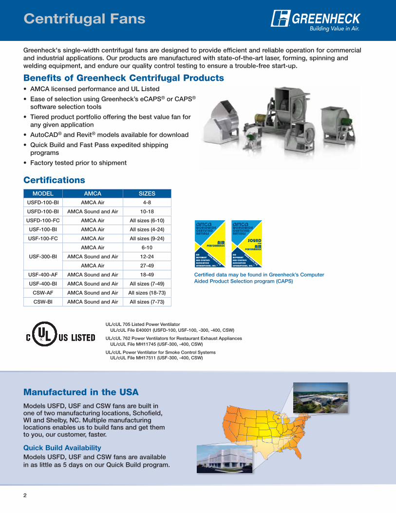
Greenheck's single-width centrifugal fans are designed to provide efficient and reliable operation for commercial and industrial applications. Our products are manufactured with state-of-the-art laser, forming, spinning and welding equipment, and endure our quality control testing to ensure a trouble-free start-up.
Benefits of Greenheck Centrifugal Products• AMCA licensed performance and UL Listed
• Ease of selection using Greenheck’s eCAPS® or CAPS® software selection tools
• Tiered product portfolio offering the best value fan for any given application
• AutoCAD® and Revit® models available for download
• Quick Build and Fast Pass expedited shipping programs
• Factory tested prior to shipment
Centrifugal Fans
MODEL AMCA SIZES
USFD-100-BI AMCA Air 4-8
USFD-100-BI AMCA Sound and Air 10-18
USFD-100-FC AMCA Air All sizes (6-10)
USF-100-BI AMCA Air All sizes (4-24)
USF-100-FC AMCA Air All sizes (9-24)
USF-300-BI
AMCA Air 6-10
AMCA Sound and Air 12-24
AMCA Air 27-49
USF-400-AF AMCA Sound and Air 18-49
USF-400-BI AMCA Sound and Air All sizes (7-49)
CSW-AF AMCA Sound and Air All sizes (18-73)
CSW-BI AMCA Sound and Air All sizes (7-73)
UL/cUL 705 Listed Power VentilatorUL/cUL File E40001 (USFD-100, USF-100, -300, -400, CSW)
UL/cUL 762 Power Ventilators for Restaurant Exhaust AppliancesUL/cUL File MH11745 (USF-300, -400, CSW)
UL/cUL Power Ventilator for Smoke Control SystemsUL/cUL File MH17511 (USF-300, -400, CSW)
Certified data may be found in Greenheck’s Computer Aided Product Selection program (CAPS)
Certifications
Manufactured in the USAModels USFD, USF and CSW fans are built in one of two manufacturing locations, Schofield, WI and Shelby, NC. Multiple manufacturing locations enables us to build fans and get them to you, our customer, faster.
Quick Build Availability
Models USFD, USF and CSW fans are available in as little as 5 days on our Quick Build program.
3
MODEL (SIZE)
Drive Frame Scroll Materials
Vari-Green®
Belt Direct Bolted Welded GalvanizedCoatedSteel
Aluminum Stainless
USFD-100
USF-100
USF-300
USF-400
CSW-BI (7-73)
CSW-AF (18-73)
Greenheck’s centrifugal products are designed to handle a variety of commercial and industrial applications:• General supply, return or exhaust systems• Emergency smoke exhaust (buildings, car parks, etc.)• Restaurant grease exhaust• Stairwell pressurization• Process heat exhaust
• Filter houses and dust collectors• Built-up or custom air handlers• Spark-resistant fume exhaust• Corrosive fume exhaust• Grain drying
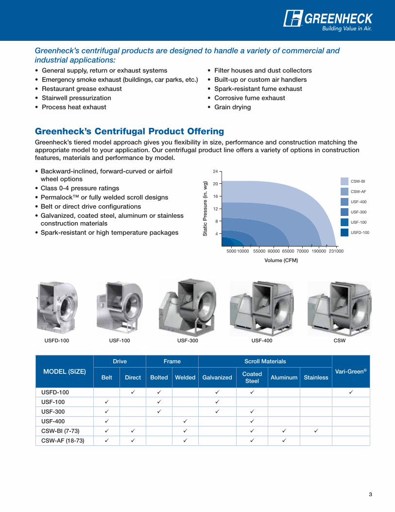
Greenheck’s Centrifugal Product OfferingGreenheck’s tiered model approach gives you flexibility in size, performance and construction matching the appropriate model to your application. Our centrifugal product line offers a variety of options in construction features, materials and performance by model.
5000 10000 55000 60000 65000 70000 190000 231000
4
8
12S
tatic
Pre
ssur
e (in
. wg
)
Volume (CFM)
CSW-BI
CSW-AF
USF-400
USF-300
USF-100
USFD-100
16
20
24• Backward-inclined, forward-curved or airfoil wheel options
• Class 0-4 pressure ratings• Permalock™ or fully welded scroll designs• Belt or direct drive configurations• Galvanized, coated steel, aluminum or stainless
construction materials• Spark-resistant or high temperature packages
USF-100 USFD-100 USF-300 USF-400 CSW
4
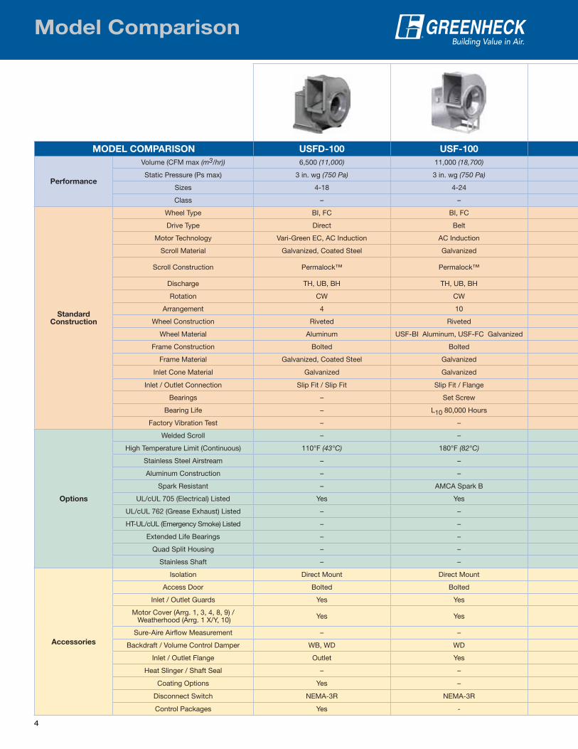
MODEL COMPARISON USFD-100 USF-100
Performance
Volume (CFM max (m3/hr)) 6,500 (11,000) 11,000 (18,700)
Static Pressure (Ps max) 3 in. wg (750 Pa) 3 in. wg (750 Pa)
Sizes 4-18 4-24
Class – –
StandardConstruction
Wheel Type BI, FC BI, FC
Drive Type Direct Belt
Motor Technology Vari-Green EC, AC Induction AC Induction
Scroll Material Galvanized, Coated Steel Galvanized
Scroll Construction Permalock™ Permalock™
Discharge TH, UB, BH TH, UB, BH
Rotation CW CW
Arrangement 4 10
Wheel Construction Riveted Riveted
Wheel Material Aluminum USF-BI Aluminum, USF-FC Galvanized
Frame Construction Bolted Bolted
Frame Material Galvanized, Coated Steel Galvanized
Inlet Cone Material Galvanized Galvanized
Inlet / Outlet Connection Slip Fit / Slip Fit Slip Fit / Flange
Bearings – Set Screw
Bearing Life – L10 80,000 Hours
Factory Vibration Test – –
Options
Welded Scroll – –
High Temperature Limit (Continuous) 110°F (43°C) 180°F (82°C)
Stainless Steel Airstream – –
Aluminum Construction – –
Spark Resistant – AMCA Spark B
UL/cUL 705 (Electrical) Listed Yes Yes
UL/cUL 762 (Grease Exhaust) Listed – –
HT-UL/cUL (Emergency Smoke) Listed – –
Extended Life Bearings – –
Quad Split Housing – –
Stainless Shaft – –
Accessories
Isolation Direct Mount Direct Mount
Access Door Bolted Bolted
Inlet / Outlet Guards Yes Yes
Motor Cover (Arrg. 1, 3, 4, 8, 9) / Weatherhood (Arrg. 1 X/Y, 10) Yes Yes
Sure-Aire Airflow Measurement – –
Backdraft / Volume Control Damper WB, WD WD
Inlet / Outlet Flange Outlet Yes
Heat Slinger / Shaft Seal – –
Coating Options Yes –
Disconnect Switch NEMA-3R NEMA-3R
Control Packages Yes -
Model Comparison
5
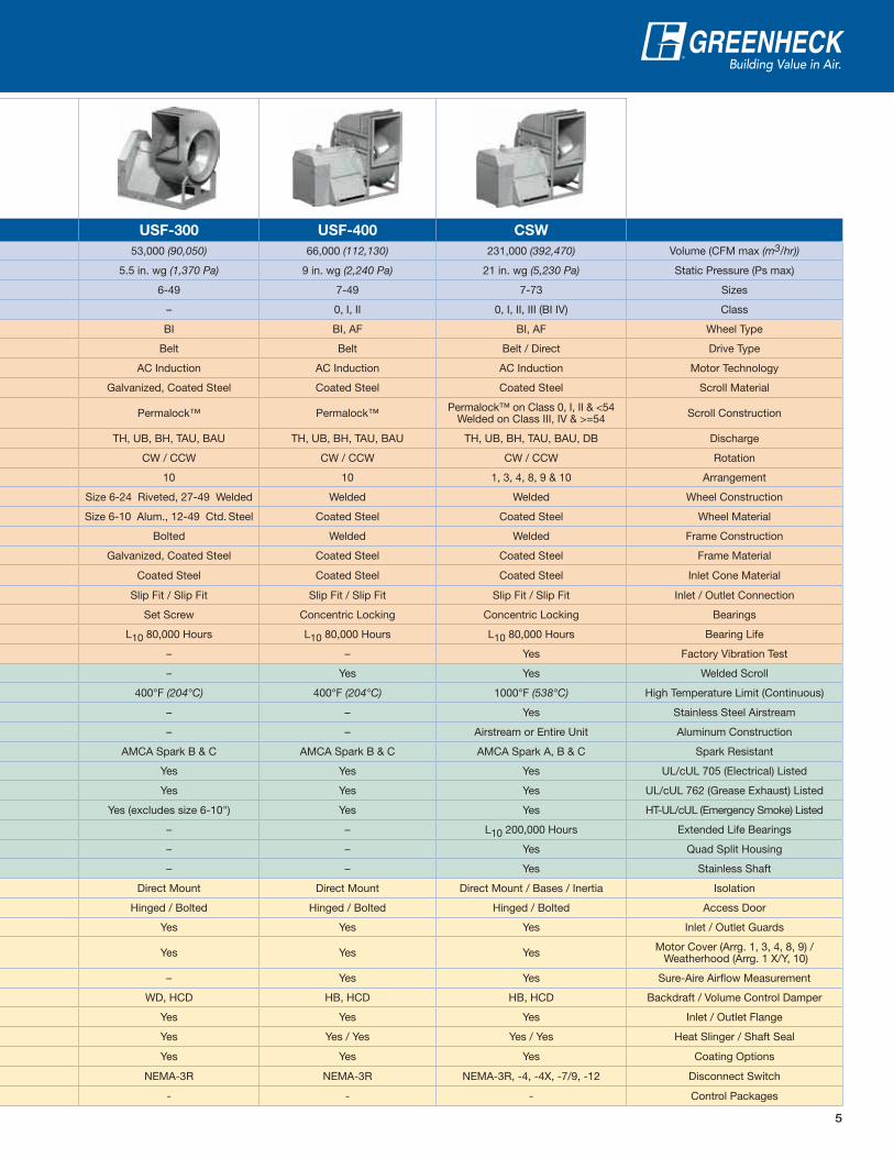
USF-300 USF-400 CSW
53,000 (90,050) 66,000 (112,130) 231,000 (392,470) Volume (CFM max (m3/hr))
5.5 in. wg (1,370 Pa) 9 in. wg (2,240 Pa) 21 in. wg (5,230 Pa) Static Pressure (Ps max)
6-49 7-49 7-73 Sizes
– 0, I, II 0, I, II, III (BI IV) Class
BI BI, AF BI, AF Wheel Type
Belt Belt Belt / Direct Drive Type
AC Induction AC Induction AC Induction Motor Technology
Galvanized, Coated Steel Coated Steel Coated Steel Scroll Material
Permalock™ Permalock™ Permalock™ on Class 0, I, II & <54Welded on Class III, IV & >=54 Scroll Construction
TH, UB, BH, TAU, BAU TH, UB, BH, TAU, BAU TH, UB, BH, TAU, BAU, DB Discharge
CW / CCW CW / CCW CW / CCW Rotation
10 10 1, 3, 4, 8, 9 & 10 Arrangement
Size 6-24 Riveted, 27-49 Welded Welded Welded Wheel Construction
Size 6-10 Alum., 12-49 Ctd. Steel Coated Steel Coated Steel Wheel Material
Bolted Welded Welded Frame Construction
Galvanized, Coated Steel Coated Steel Coated Steel Frame Material
Coated Steel Coated Steel Coated Steel Inlet Cone Material
Slip Fit / Slip Fit Slip Fit / Slip Fit Slip Fit / Slip Fit Inlet / Outlet Connection
Set Screw Concentric Locking Concentric Locking Bearings
L10 80,000 Hours L10 80,000 Hours L10 80,000 Hours Bearing Life
– – Yes Factory Vibration Test
– Yes Yes Welded Scroll
400°F (204°C) 400°F (204°C) 1000°F (538°C) High Temperature Limit (Continuous)
– – Yes Stainless Steel Airstream
– – Airstream or Entire Unit Aluminum Construction
AMCA Spark B & C AMCA Spark B & C AMCA Spark A, B & C Spark Resistant
Yes Yes Yes UL/cUL 705 (Electrical) Listed
Yes Yes Yes UL/cUL 762 (Grease Exhaust) Listed
Yes (excludes size 6-10") Yes Yes HT-UL/cUL (Emergency Smoke) Listed
– – L10 200,000 Hours Extended Life Bearings
– – Yes Quad Split Housing
– – Yes Stainless Shaft
Direct Mount Direct Mount Direct Mount / Bases / Inertia Isolation
Hinged / Bolted Hinged / Bolted Hinged / Bolted Access Door
Yes Yes Yes Inlet / Outlet Guards
Yes Yes Yes Motor Cover (Arrg. 1, 3, 4, 8, 9) / Weatherhood (Arrg. 1 X/Y, 10)
– Yes Yes Sure-Aire Airflow Measurement
WD, HCD HB, HCD HB, HCD Backdraft / Volume Control Damper
Yes Yes Yes Inlet / Outlet Flange
Yes Yes / Yes Yes / Yes Heat Slinger / Shaft Seal
Yes Yes Yes Coating Options
NEMA-3R NEMA-3R NEMA-3R, -4, -4X, -7/9, -12 Disconnect Switch
- - - Control Packages
6
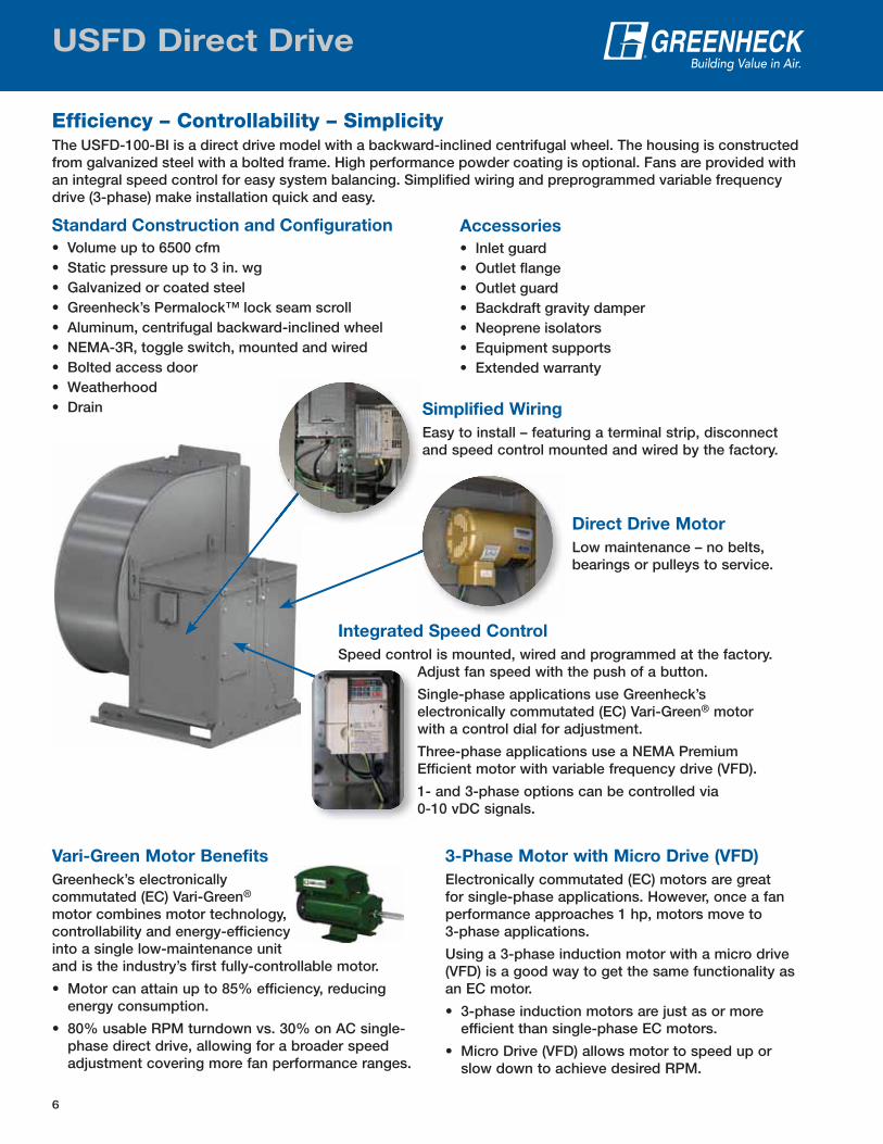
Integrated Speed Control
Speed control is mounted, wired and programmed at the factory. Adjust fan speed with the push of a button.
Single-phase applications use Greenheck’s electronically commutated (EC) Vari-Green® motor with a control dial for adjustment.
Three-phase applications use a NEMA Premium Efficient motor with variable frequency drive (VFD).
1- and 3-phase options can be controlled via 0-10 vDC signals.
Accessories
• Inlet guard• Outlet flange• Outlet guard• Backdraft gravity damper• Neoprene isolators• Equipment supports• Extended warranty
USFD Direct Drive
Standard Construction and Configuration
• Volume up to 6500 cfm• Static pressure up to 3 in. wg• Galvanized or coated steel• Greenheck’s Permalock™ lock seam scroll• Aluminum, centrifugal backward-inclined wheel• NEMA-3R, toggle switch, mounted and wired• Bolted access door• Weatherhood• Drain
Efficiency – Controllability – SimplicityThe USFD-100-BI is a direct drive model with a backward-inclined centrifugal wheel. The housing is constructed from galvanized steel with a bolted frame. High performance powder coating is optional. Fans are provided with an integral speed control for easy system balancing. Simplified wiring and preprogrammed variable frequency drive (3-phase) make installation quick and easy.
Simplified Wiring
Easy to install – featuring a terminal strip, disconnect and speed control mounted and wired by the factory.
Direct Drive Motor
Low maintenance – no belts, bearings or pulleys to service.
Vari-Green Motor Benefits
Greenheck’s electronically commutated (EC) Vari-Green® motor combines motor technology, controllability and energy-efficiency into a single low-maintenance unit and is the industry’s first fully-controllable motor.
• Motor can attain up to 85% efficiency, reducing energy consumption.
• 80% usable RPM turndown vs. 30% on AC single-phase direct drive, allowing for a broader speed adjustment covering more fan performance ranges.
3-Phase Motor with Micro Drive (VFD)
Electronically commutated (EC) motors are great for single-phase applications. However, once a fan performance approaches 1 hp, motors move to 3-phase applications.
Using a 3-phase induction motor with a micro drive (VFD) is a good way to get the same functionality as an EC motor.
• 3-phase induction motors are just as or more efficient than single-phase EC motors.
• Micro Drive (VFD) allows motor to speed up or slow down to achieve desired RPM.
7
Centrifugal Fan Applications
UL/cUL 705 Listed Power VentilatorUL/cUL File E40001 (USFD-100, USF-100, -300, -400, CSW)
UL/cUL 762 Power Ventilators for Restaurant Exhaust AppliancesUL/cUL File MH11745 (USF-300, -400, CSW)
UL/cUL Power Ventilator for Smoke Control SystemsUL/cUL File MH17511 (USF-300, -400, CSW)
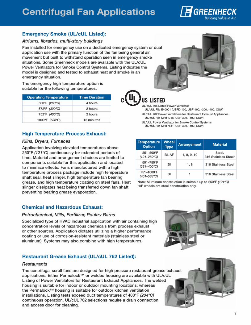
Emergency Smoke (UL/cUL Listed):
Atriums, libraries, multi-story buildingsFan installed for emergency use on a dedicated emergency system or dual application use with the primary function of the fan being general air movement but built to withstand operation seen in emergency smoke situations. Some Greenheck models are available with the UL/cUL Power Ventilators for Smoke Control Systems. Listing indicates the model is designed and tested to exhaust heat and smoke in an emergency situation.
The emergency high temperature option is suitable for the following temperatures:
dual
Operating Temperature Time Duration
500ºF (260ºC) 4 hours
572ºF (300ºC) 2 hours
752ºF (400ºC) 2 hours
1000ºF (538ºC) 15 minutes
Temperature
Option
Wheel
TypeArrangement Material
251–500ºF (121–260ºC)
BI, AF 1, 8, 9, 10Steel,
316 Stainless Steel*
501–750ºF (261–400ºC)
BI 1, 8 316 Stainless Steel
751–1000ºF (401–538ºC)
BI 1 316 Stainless Steel
Note: Aluminum construction is suitable up to 250ºF (121ºC)* AF wheels are steel construction only.
High Temperature Process Exhaust:
Kilns, Dryers, FurnacesApplication involving elevated temperatures above 250°F (121°C) continuously for extended periods of time. Material and arrangement choices are limited to components suitable for this application and located to minimize effects. Fans manufactured with a high temperature process package include high temperature shaft seal, heat slinger, high temperature fan bearing grease, and high temperature coating on steel fans. Heat slinger dissipates heat being transferred down fan shaft preventing bearing grease evaporation.
Chemical and Hazardous Exhaust:
Petrochemical, Mills, Fertilizer, Poultry BarnsSpecialized type of HVAC industrial application with air containing high concentration levels of hazardous chemicals from process exhaust or other sources. Application dictates utilizing a higher performance coating or use of corrosion-resistant materials (stainless steel or aluminum). Systems may also combine with high temperatures.
Restaurant Grease Exhaust (UL/cUL 762 Listed):
RestaurantsThe centrifugal scroll fans are designed for high pressure restaurant grease exhaust applications. Either Permalock™ or welded housing are available with UL/cUL Listing of Power Ventilators for Restaurant Exhaust Appliances. The welded housing is suitable for indoor or outdoor mounting locations, whereas the Permalock™ housing is suitable for outdoor kitchen ventilation installations. Listing tests exceed duct temperatures of 400°F (204°C) continuous operation. UL/cUL 762 selections require a drain connection and access door for cleaning.
e exhaust cULd
8
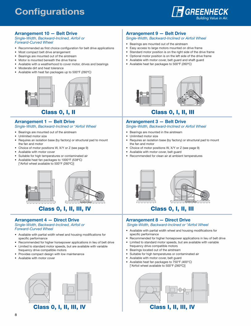
Configurations
Arrangement 1 — Belt DriveSingle-Width, Backward-Inclined or *Airfoil Wheel
• Bearings are mounted out of the airstream• Unlimited motor size• Requires an isolation base (by factory) or structural pad to mount
the fan and motor• Choice of motor positions W, X/Y or Z (see page 9)• Available with motor cover• Suitable for high temperatures or contaminated air• Available heat fan packages to 1000°F (538ºC)
[*Airfoil wheel available to 500°F (260ºC)]
Isolation Base
Class 0, I, II, III, IV
Arrangement 4 — Direct DriveSingle-Width, Backward-Inclined, Airfoil or Forward-Curved Wheel
• Available with partial width wheel and housing modifications for specific performance
• Recommended for higher horsepower applications in lieu of belt drive• Limited to standard motor speeds, but are available with variable
frequency drive compatible motors• Provides compact design with low maintenance• Available with motor cover
Class 0, I, II, III, IV
Arrangement 9 — Belt DriveSingle-Width, Backward-Inclined or Airfoil Wheel
• Bearings are mounted out of the airstream• Easy access to large motors mounted on drive frame• Standard motor position is on the right side of the drive frame• Optional motor position is on the left side of the drive frame• Available with motor cover, belt guard and shaft guard• Available heat fan packages to 500°F (260ºC)
Class 0, I, II, III
Arrangement 3 — Belt DriveSingle-Width, Backward-Inclined or Airfoil Wheel
• Bearings are mounted in the airstream• Unlimited motor size• Requires an isolation base (by factory) or structural pad to mount
the fan and motor• Choice of motor positions W, X/Y or Z (see page 9)• Available with motor cover, belt guard• Recommended for clean air at ambient temperatures
Isolation Base
Class 0, I, II, III
Arrangement 8 — Direct Drive Single-Width, Backward-Inclined or *Airfoil Wheel
• Available with partial width wheel and housing modifications for specific performance
• Recommended for higher horsepower applications in lieu of belt drive• Limited to standard motor speeds, but are available with variable
frequency drive compatible motors• Bearings located out of the airstream• Suitable for high temperatures or contaminated air• Available with motor cover, belt guard• Available heat fan packages to 750°F (400°C)
[*Airfoil wheel available to 500°F (260ºC)]
Class I, II, III, IV
Arrangement 10 — Belt DriveSingle-Width, Backward-Inclined, Airfoil or Forward-Curved Wheel
• Recommended as first choice configuration for belt drive applications• Most compact belt drive arrangement• Bearings are mounted out of the airstream• Motor is mounted beneath the drive frame• Available with a weatherhood to cover motor, drives and bearings• Moderate dirt and heat tolerance• Available with heat fan packages up to 500°F (260ºC)
Class 0, I, II
9
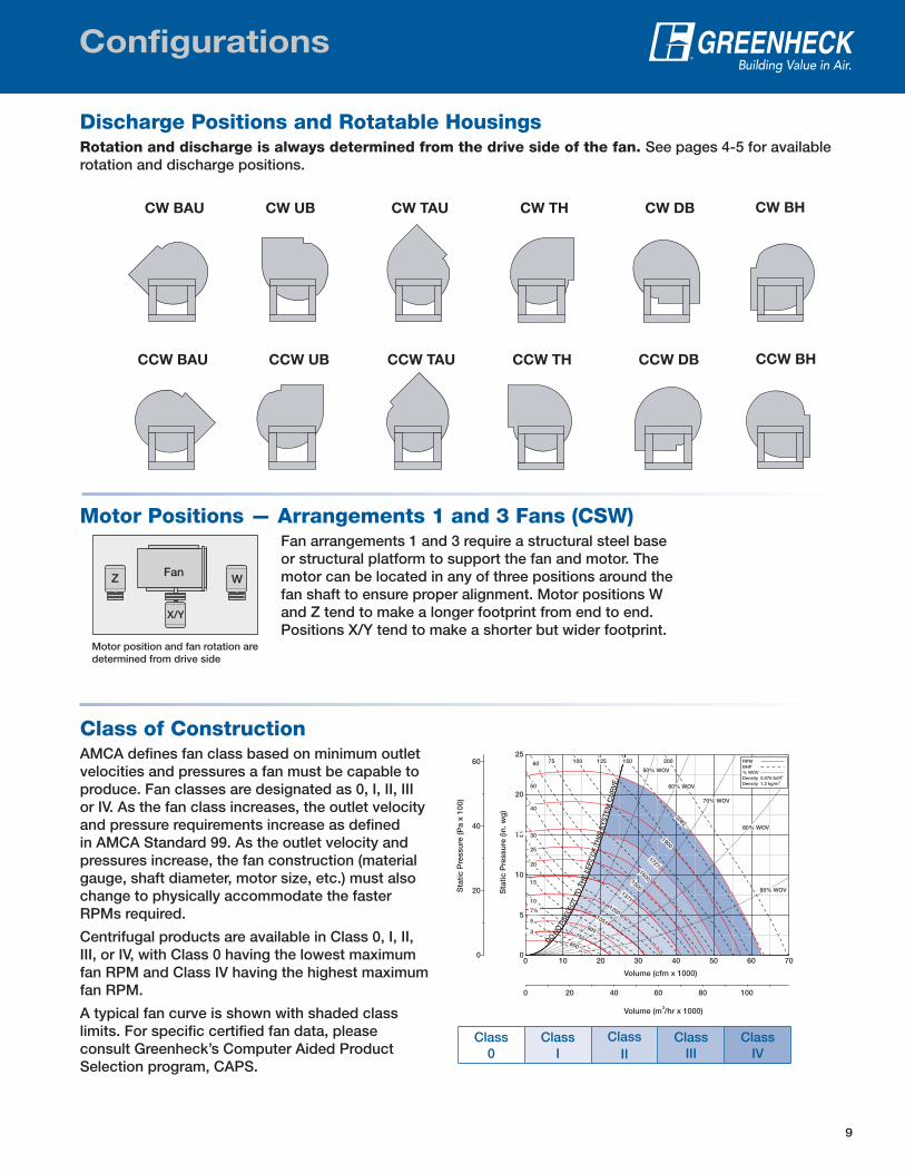
Discharge Positions and Rotatable HousingsRotation and discharge is always determined from the drive side of the fan. See pages 4-5 for available rotation and discharge positions.
Configurations
CW TH
CCW TH
CW DB
CCW DB
CW BH
CCW BH
CW TAU
CCW TAU
CW UB
CCW UB
CW BAU
CCW BAU
Motor Positions — Arrangements 1 and 3 Fans (CSW)Fan arrangements 1 and 3 require a structural steel base or structural platform to support the fan and motor. The motor can be located in any of three positions around the fan shaft to ensure proper alignment. Motor positions W and Z tend to make a longer footprint from end to end. Positions X/Y tend to make a shorter but wider footprint.
X/Y
FanZ W
Motor position and fan rotation aredetermined from drive side
Class of ConstructionAMCA defines fan class based on minimum outlet velocities and pressures a fan must be capable to produce. Fan classes are designated as 0, I, II, III or IV. As the fan class increases, the outlet velocity and pressure requirements increase as defined in AMCA Standard 99. As the outlet velocity and pressures increase, the fan construction (material gauge, shaft diameter, motor size, etc.) must also change to physically accommodate the faster RPMs required.
Centrifugal products are available in Class 0, I, II, III, or IV, with Class 0 having the lowest maximum fan RPM and Class IV having the highest maximum fan RPM.
A typical fan curve is shown with shaded class limits. For specific certified fan data, please consult Greenheck’s Computer Aided Product Selection program, CAPS.
Class 0
Class I
ClassII
Class III
Class IV
Sta
tic P
ress
ure
(in. w
g)
Sta
tic P
ress
ure
(Pa
x 10
0)
Volume (cfm x 1000)
3Volume (m /hr x 1000)
0 20 40 60 80 100
0
20
40
60
DO NO
T SE
LEC
T TO
TH
E LE
FT O
F TH
IS S
YS
TEM
CU
RV
E
0 10 20 30 40 50 60 700
5
10
15
20
25
RPMBHP% WOVDensity 0.075 lb/ft3
Density 1.2 kg/m3
75075033
600600
900900
10511051
12001200
13711371
15001500
50% WOV50% WOV
60% WOV60% WOV
70% WOV70% WOV
80% WOV80% WOV
90% WOV90% WOV
19001900
55
7½ 7½
1010
1515
2020
17271727
2525
4040
3030
16001600
5050
6060 7575
20822082
125125100100 150150 200200
10
Construction Options
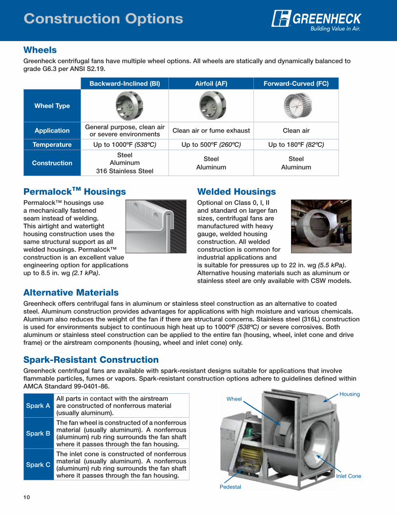
Alternative MaterialsGreenheck offers centrifugal fans in aluminum or stainless steel construction as an alternative to coated steel. Aluminum construction provides advantages for applications with high moisture and various chemicals. Aluminum also reduces the weight of the fan if there are structural concerns. Stainless steel (316L) construction is used for environments subject to continuous high heat up to 1000ºF (538ºC) or severe corrosives. Both aluminum or stainless steel construction can be applied to the entire fan (housing, wheel, inlet cone and drive frame) or the airstream components (housing, wheel and inlet cone) only.
Spark-Resistant ConstructionGreenheck centrifugal fans are available with spark-resistant designs suitable for applications that involve flammable particles, fumes or vapors. Spark-resistant construction options adhere to guidelines defined within AMCA Standard 99-0401-86.
Spark AAll parts in contact with the airstream are constructed of nonferrous material (usually aluminum).
Spark B
The fan wheel is constructed of a nonferrous material (usually aluminum). A nonferrous (aluminum) rub ring surrounds the fan shaft where it passes through the fan housing.
Spark C
The inlet cone is constructed of nonferrous material (usually aluminum). A nonferrous (aluminum) rub ring surrounds the fan shaft where it passes through the fan housing.
Permalock™ HousingsPermalock™ housings use a mechanically fastened seam instead of welding. This airtight and watertight housing construction uses the same structural support as all welded housings. Permalock™ construction is an excellent value engineering option for applications up to 8.5 in. wg (2.1 kPa).
Welded HousingsOptional on Class 0, I, II and standard on larger fan sizes, centrifugal fans are manufactured with heavy gauge, welded housing construction. All welded construction is common for industrial applications and is suitable for pressures up to 22 in. wg (5.5 kPa). Alternative housing materials such as aluminum or stainless steel are only available with CSW models.
Backward-Inclined (BI) Airfoil (AF) Forward-Curved (FC)
Wheel Type
ApplicationGeneral purpose, clean air
or severe environments Clean air or fume exhaust Clean air
Temperature Up to 1000ºF (538ºC) Up to 500ºF (260ºC) Up to 180ºF (82ºC)
Construction
SteelAluminum
316 Stainless Steel
SteelAluminum
SteelAluminum
WheelsGreenheck centrifugal fans have multiple wheel options. All wheels are statically and dynamically balanced to grade G6.3 per ANSI S2.19.
Housing
Inlet Cone
Wheel
Pedestal
11
Construction Options
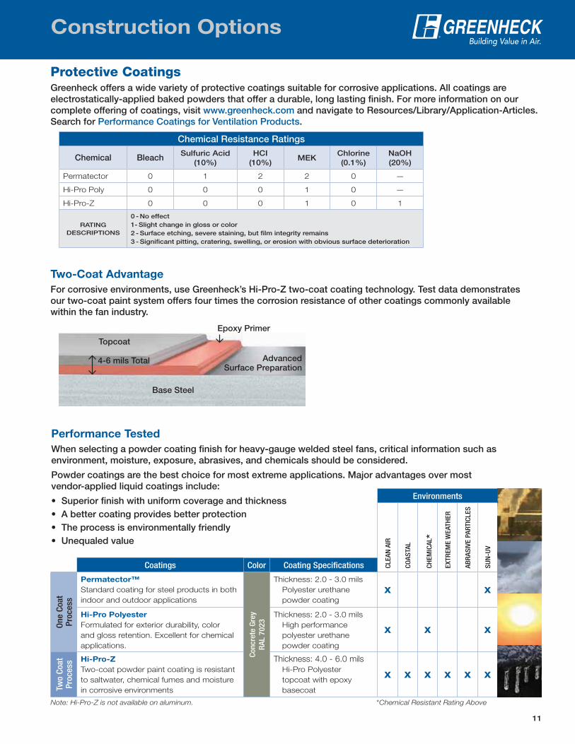
Performance Tested
When selecting a powder coating finish for heavy-gauge welded steel fans, critical information such as environment, moisture, exposure, abrasives, and chemicals should be considered.
Powder coatings are the best choice for most extreme applications. Major advantages over most vendor-applied liquid coatings include:
• Superior finish with uniform coverage and thickness• A better coating provides better protection• The process is environmentally friendly• Unequaled value
Environments
CLEA
N A
IR
COAS
TAL
CHEM
ICAL
*
EXTR
EME
WEA
THER
ABR
ASIV
E PA
RTIC
LES
SUN
-UV
Coatings Color Coating Specifications
One
Coa
t Pr
oces
s
Permatector™
Standard coating for steel products in both
indoor and outdoor applications
Conc
rete
Gre
y R
AL 7
023
Thickness: 2.0 - 3.0 mils
Polyester urethane
powder coating
X X
Hi-Pro Polyester
Formulated for exterior durability, color
and gloss retention. Excellent for chemical
applications.
Thickness: 2.0 - 3.0 mils
High performance
polyester urethane
powder coating
X X X
Two
Coat
Pr
oces
s Hi-Pro-Z
Two-coat powder paint coating is resistant
to saltwater, chemical fumes and moisture
in corrosive environments
Thickness: 4.0 - 6.0 mils
Hi-Pro Polyester
topcoat with epoxy
basecoat
X X X X X X
Note: Hi-Pro-Z is not available on aluminum. * Chemical Resistant Rating Above
Two-Coat Advantage
For corrosive environments, use Greenheck’s Hi-Pro-Z two-coat coating technology. Test data demonstrates our two-coat paint system offers four times the corrosion resistance of other coatings commonly available within the fan industry.
4-6 mils Total
Epoxy Primer
Topcoat
Base Steel
AdvancedSurface Preparation
Protective CoatingsGreenheck offers a wide variety of protective coatings suitable for corrosive applications. All coatings are electrostatically-applied baked powders that offer a durable, long lasting finish. For more information on our complete offering of coatings, visit www.greenheck.com and navigate to Resources/Library/Application-Articles. Search for Performance Coatings for Ventilation Products.
Chemical Resistance Ratings
Chemical Bleach Sulfuric Acid (10%)
HCI (10%)
MEKChlorine (0.1%)
NaOH (20%)
Permatector 0 1 2 2 0 —
Hi-Pro Poly 0 0 0 1 0 —
Hi-Pro-Z 0 0 0 1 0 1
RATING DESCRIPTIONS
0 - No effect1- Slight change in gloss or color2 - Surface etching, severe staining, but film integrity remains3 - Significant pitting, cratering, swelling, or erosion with obvious surface deterioration
12
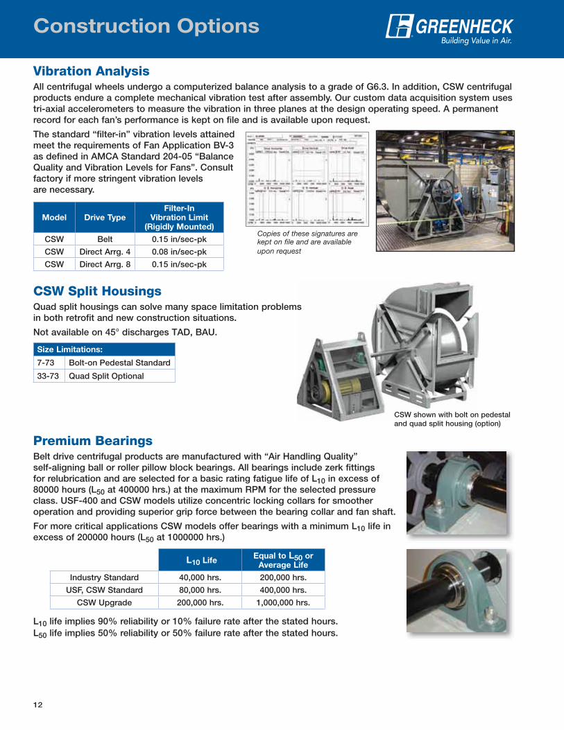
Vibration AnalysisAll centrifugal wheels undergo a computerized balance analysis to a grade of G6.3. In addition, CSW centrifugal products endure a complete mechanical vibration test after assembly. Our custom data acquisition system uses tri-axial accelerometers to measure the vibration in three planes at the design operating speed. A permanent record for each fan’s performance is kept on file and is available upon request.
The standard “filter-in” vibration levels attained meet the requirements of Fan Application BV-3 as defined in AMCA Standard 204-05 “Balance Quality and Vibration Levels for Fans”. Consult factory if more stringent vibration levels are necessary.
Model Drive TypeFilter-In
Vibration Limit(Rigidly Mounted)
CSW Belt 0.15 in/sec-pk
CSW Direct Arrg. 4 0.08 in/sec-pk
CSW Direct Arrg. 8 0.15 in/sec-pk
Construction Options
CSW shown with bolt on pedestal and quad split housing (option)CSW shown with bolt on
d d lit h i (
CSW Split HousingsQuad split housings can solve many space limitation problems in both retrofit and new construction situations.
Not available on 45° discharges TAD, BAU.
Size Limitations:
7-73 Bolt-on Pedestal Standard
33-73 Quad Split Optional
Copies of these signatures are kept on file and are available upon request
Premium BearingsBelt drive centrifugal products are manufactured with “Air Handling Quality” self-aligning ball or roller pillow block bearings. All bearings include zerk fittings for relubrication and are selected for a basic rating fatigue life of L10 in excess of 80000 hours (L50 at 400000 hrs.) at the maximum RPM for the selected pressure class. USF-400 and CSW models utilize concentric locking collars for smoother operation and providing superior grip force between the bearing collar and fan shaft.
For more critical applications CSW models offer bearings with a minimum L10 life in excess of 200000 hours (L50 at 1000000 hrs.)
L10 life implies 90% reliability or 10% failure rate after the stated hours.L50 life implies 50% reliability or 50% failure rate after the stated hours.
L10 LifeEqual to L50 or
Average Life
Industry Standard 40,000 hrs. 200,000 hrs.
USF, CSW Standard 80,000 hrs. 400,000 hrs.
CSW Upgrade 200,000 hrs. 1,000,000 hrs.
13
Accessories
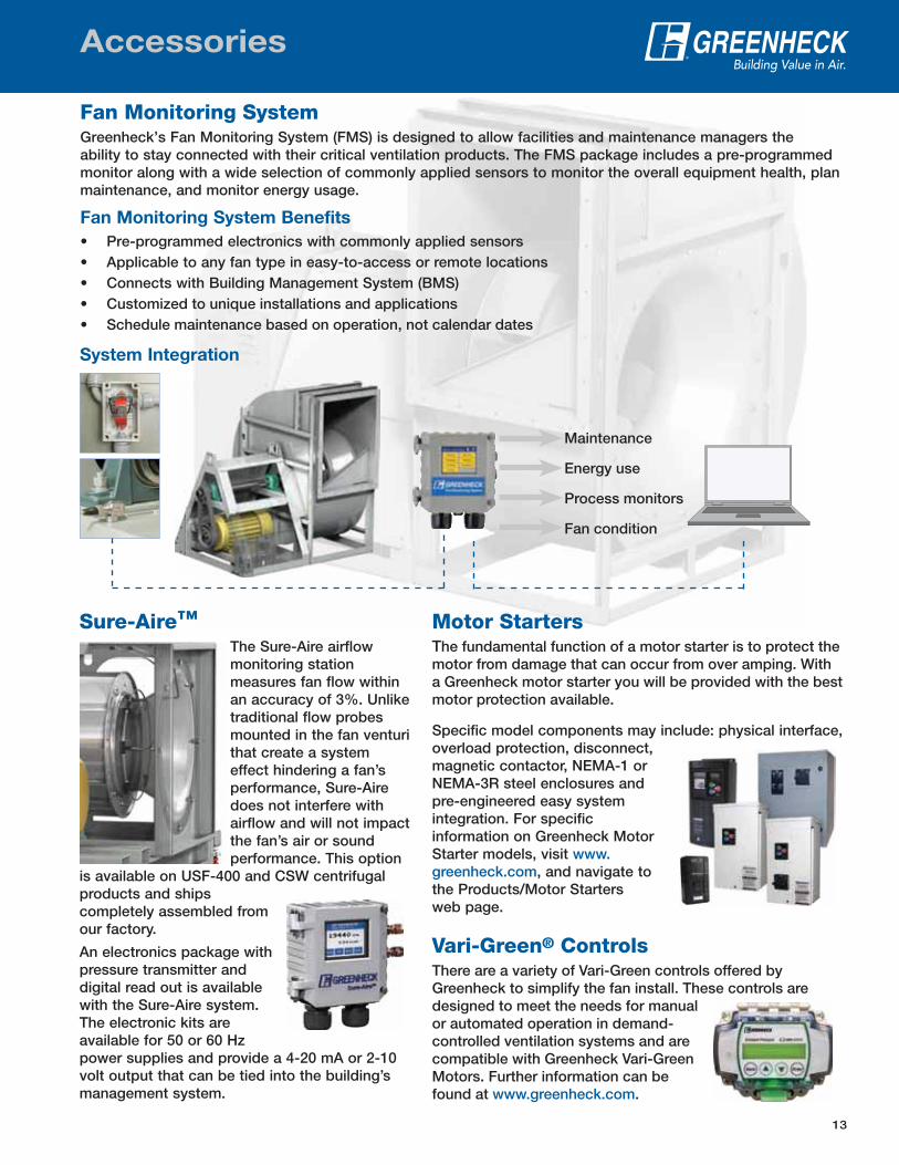
Fan Monitoring SystemGreenheck’s Fan Monitoring System (FMS) is designed to allow facilities and maintenance managers the ability to stay connected with their critical ventilation products. The FMS package includes a pre-programmed monitor along with a wide selection of commonly applied sensors to monitor the overall equipment health, plan maintenance, and monitor energy usage.
Fan Monitoring System Benefits
• Pre-programmed electronics with commonly applied sensors• Applicable to any fan type in easy-to-access or remote locations• Connects with Building Management System (BMS)• Customized to unique installations and applications• Schedule maintenance based on operation, not calendar dates
System Integration
Maintenance
Energy use
Process monitors
Fan condition
Motor StartersThe fundamental function of a motor starter is to protect the motor from damage that can occur from over amping. With a Greenheck motor starter you will be provided with the best motor protection available.
Specific model components may include: physical interface, overload protection, disconnect, magnetic contactor, NEMA-1 or NEMA-3R steel enclosures and pre-engineered easy system integration. For specific information on Greenheck Motor Starter models, visit www.greenheck.com, and navigate to the Products/Motor Starters web page.
Vari-Green® ControlsThere are a variety of Vari-Green controls offered by Greenheck to simplify the fan install. These controls are designed to meet the needs for manual or automated operation in demand-controlled ventilation systems and are compatible with Greenheck Vari-Green Motors. Further information can be found at www.greenheck.com.
Sure-Aire™The Sure-Aire airflow monitoring station measures fan flow within an accuracy of 3%. Unlike traditional flow probes mounted in the fan venturi that create a system effect hindering a fan’s performance, Sure-Aire does not interfere with airflow and will not impact the fan’s air or sound performance. This option
is available on USF-400 and CSW centrifugal products and ships completely assembled from our factory.
An electronics package with pressure transmitter and digital read out is available with the Sure-Aire system. The electronic kits are available for 50 or 60 Hz power supplies and provide a 4-20 mA or 2-10 volt output that can be tied into the building’s management system.
14
Accessories
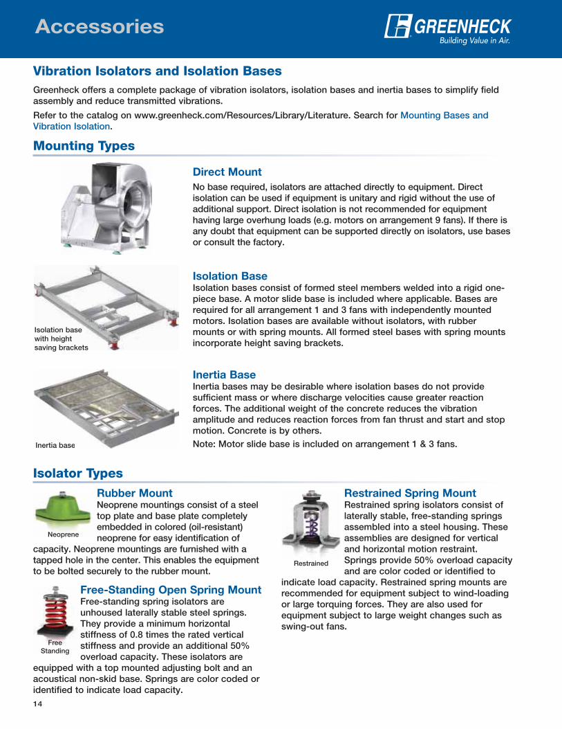
Vibration Isolators and Isolation BasesGreenheck offers a complete package of vibration isolators, isolation bases and inertia bases to simplify field assembly and reduce transmitted vibrations.
Refer to the catalog on www.greenheck.com/Resources/Library/Literature. Search for Mounting Bases and Vibration Isolation.
Isolator Types
Rubber MountNeoprene mountings consist of a steel top plate and base plate completely embedded in colored (oil-resistant) neoprene for easy identification of
capacity. Neoprene mountings are furnished with a tapped hole in the center. This enables the equipment to be bolted securely to the rubber mount.
Free-Standing Open Spring MountFree-standing spring isolators are unhoused laterally stable steel springs. They provide a minimum horizontal stiffness of 0.8 times the rated vertical stiffness and provide an additional 50% overload capacity. These isolators are
equipped with a top mounted adjusting bolt and an acoustical non-skid base. Springs are color coded or identified to indicate load capacity.
Restrained Spring MountRestrained spring isolators consist of laterally stable, free-standing springs assembled into a steel housing. These assemblies are designed for vertical and horizontal motion restraint. Springs provide 50% overload capacity and are color coded or identified to
indicate load capacity. Restrained spring mounts are recommended for equipment subject to wind-loading or large torquing forces. They are also used for equipment subject to large weight changes such as swing-out fans.
Restrained
Neoprene
Free Standing
Mounting Types
Isolation base with height saving brackets
Inertia baseInertia base
Direct Mount
No base required, isolators are attached directly to equipment. Direct isolation can be used if equipment is unitary and rigid without the use of additional support. Direct isolation is not recommended for equipment having large overhung loads (e.g. motors on arrangement 9 fans). If there is any doubt that equipment can be supported directly on isolators, use bases or consult the factory.
Isolation BaseIsolation bases consist of formed steel members welded into a rigid one-piece base. A motor slide base is included where applicable. Bases are required for all arrangement 1 and 3 fans with independently mounted motors. Isolation bases are available without isolators, with rubber mounts or with spring mounts. All formed steel bases with spring mounts incorporate height saving brackets.
Inertia BaseInertia bases may be desirable where isolation bases do not provide sufficient mass or where discharge velocities cause greater reaction forces. The additional weight of the concrete reduces the vibration amplitude and reduces reaction forces from fan thrust and start and stop motion. Concrete is by others.Note: Motor slide base is included on arrangement 1 & 3 fans.
15
Accessories
Weatherhood (Arrg. 1 X/Y, 10)
Vented steel weatherhoods protect the motor and drive components from rain, moisture, dust, and dirt. Weatherhoods meet OSHA guidelines and are easily removed for service access.
Belt Guard
Belt guards are designed to allow easy access to the belts and pulleys for service. All belt guards include tachometer openings to monitor the fan speed as well as an access panel for testing belt tension. Belt guards meet OSHA guidelines.
Shaft Guard
Shaft guards are designed to cover shafts and bearings on arrangements 1, 8, or 9 configurations. Extended lube lines are optional for bearing lubrication without removal of the guard. Shaft guards meet OSHA guidelines.
Motor Cover (Arrg. 1 W or Z, 3, 4, 8, 9)
A weatherproof motor cover shields the motor components from dust, dirt and moisture for outdoor installations.
Inlet and Outlet Guards
Removable inlet and outlet guards provide protection for personnel and equipment in non-ducted installations. Inlet and outlet guards meet OSHA guidelines. Steel only.
Inlet and Outlet Flanges
Optional inlet flanges on single-width fans are pre-punched and welded to the inlet collar. Punched outlet flanges are standard on fan sizes 33-73.
Access Door
Bolted or hinged access doors provide access for cleaning or inspection. Access doors are standard on downblast discharge fans.
Inlet Companion Flange
Punched companion inlet flanges are available on single-width fans.
Drain with Plug
A one-inch (25 mm) threaded drain connection is located at the bottom of the fan housing to drain water that may accumulate.
Heat Slinger
The heat slinger is an aluminum cooling disc mounted on the fan shaft between the inboard bearing and the blower housing to dissipate heat conducted along the fan shaft. Heat slingers are not available for Arrangement 3 or 4 fans.
Stainless Steel Shaft
Stainless steel fan shafts are available for applications where standard carbon steel shafts may exhibit excessive corrosion or heat stress.
Shaft Seal
A felt, neoprene, or ceramic shaft seal with a rub ring is available for operation at high temperatures or for exhausting contaminated air.
Extended Life Bearings
Extended life bearings are selected for a basic rating fatigue life L10 per ABMA Standards in excess of 200,000 hours at the maximum RPM. L10 is the life associated with 90% reliability of a bearing.
Extended Lubrication Lines
Single-width fans are available with flexible nylon or copper tubing extending from the bearings to conveniently located grease fittings mounted on the fan pedestal (or on the exterior of weatherhood if a weatherhood is supplied).
Disconnect Switch
Greenheck offers a wide selection of NEMA rated fusible or non-fusible disconnect switches. Switches can be factory mounted or shipped loose for field installation.
Grease Containment
Grease trap is designed to collect grease residue to avoid drainage onto roof surface. Grease traps ship loose for field installation.
Backdraft Damper
Backdraft dampers are available in galvanized, painted steel or aluminum construction and include counterweights for tight closure when the fan is de-energized.
Volume Control:Volume Control Damper
Control dampers are available in painted steel, aluminum or stainless steel. Actuator options include manual quadrant or electric.
VFD Rated Motor
Variable frequency drives (VFD’s) change the frequency of the input power to the motor, which results in changing the motor’s speed. Changing the speed of the fan provides the greatest potential for energy savings at partial loads.
P.O. Box 410 • Schofield, WI 54476-0410 • Phone (715) 359-6171 • greenheck.com
Prepared to SupportGreen Building Efforts
As a result of our commitment to continuous improvement, Greenheck reserves the right to change
specifications without notice.
Product warranties can be found online at Greenheck.com, either on the specific product page or in
the literature section of the website at Greenheck.com/Resources/Library/Literature.
Our Commitment
00.CVI.1033 R4 11-2018 Copyright © 2018 Greenheck Fan Corp.
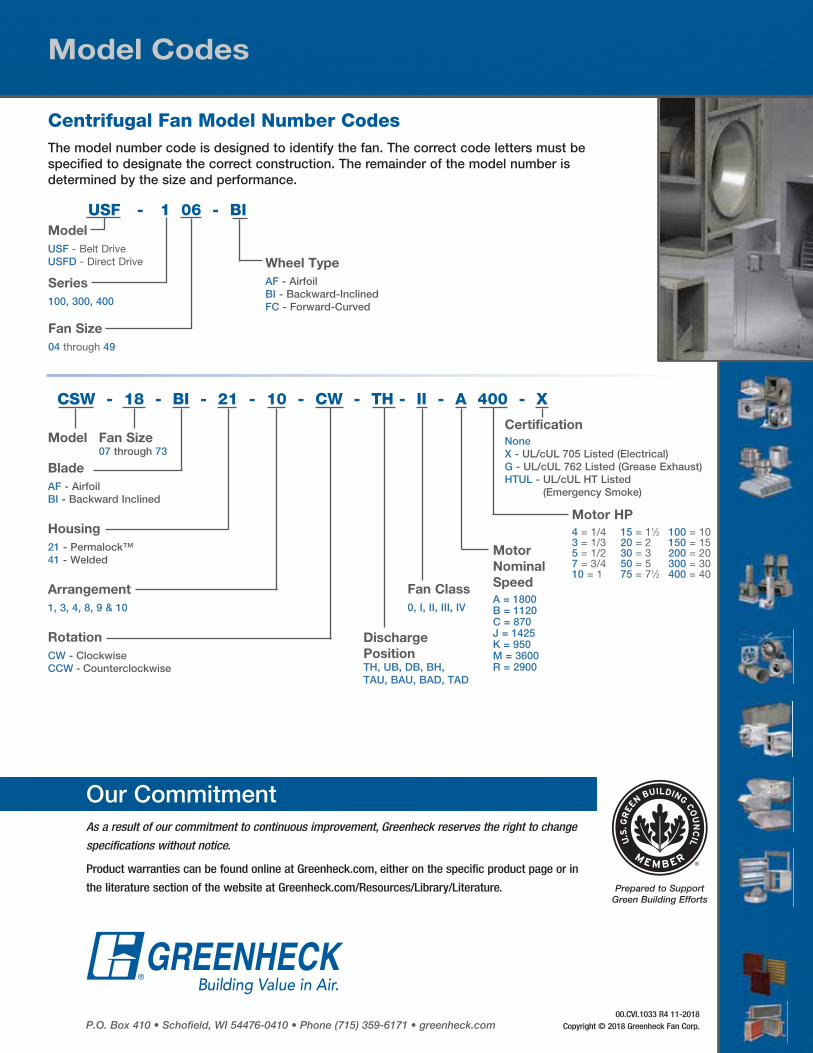
Centrifugal Fan Model Number CodesThe model number code is designed to identify the fan. The correct code letters must be specified to designate the correct construction. The remainder of the model number is determined by the size and performance.
Model Codes
USF - 1 06 - BI
Series
100, 300, 400
Fan Size
04 through 49
Wheel Type
AF - Airfoil BI - Backward-InclinedFC - Forward-Curved
Model
USF - Belt Drive USFD - Direct Drive
Certification
NoneX - UL/cUL 705 Listed (Electrical)G - UL/cUL 762 Listed (Grease Exhaust)HTUL - UL/cUL HT Listed
(Emergency Smoke)
Motor HP
4 = 1/4 15 = 11⁄2 100 = 103 = 1/3 20 = 2 150 = 155 = 1/2 30 = 3 200 = 207 = 3/4 50 = 5 300 = 3010 = 1 75 = 71⁄2 400 = 40
CSW - 18 - BI - 21 - 10 - CW - TH - II - A 400 - X
Fan Size07 through 73
Fan Class
0, I, II, III, IV
Discharge
PositionTH, UB, DB, BH, TAU, BAU, BAD, TAD
Motor
Nominal
Speed
A = 1800B = 1120C = 870J = 1425K = 950M = 3600R = 2900
Model
Blade
AF - AirfoilBI - Backward Inclined
Housing
21 - Permalock™ 41 - Welded
Arrangement
1, 3, 4, 8, 9 & 10
Rotation
CW - ClockwiseCCW - Counterclockwise