user’s operating instructions - kp evans combi instant 80e 105e user.pdf · user’s operating...
TRANSCRIPT

Baxi Combi Instant 80e & 105e
Gas Fired Wall Mounted CombinationBoiler
User’s Operating Instructions
Please keep these instructions safe.Should you move house, please hand
them over to the next occupier.
2
Baxi is one of the leading manufacturers of domestic
heating products in the UK.
Our first priority is to give a high quality service to our
customers. Quality is designed into every Baxi product
- products which fulfil the demands and needs of
customers, offering choice, efficiency and reliability.
To keep ahead of changing trends, we have made a
commitment to develop new ideas using the
latest technology - with the aim of continuing to
make the products that customers want to buy.
Everyone who works at Baxi has a commitment to
quality because we know that satisfied customers
mean continued success.
We hope you get a satisfactory service from Baxi. If
not, please let us know.
Natural Gas
Baxi Combi Instant 80eG.C.No 47 075 13
Baxi Combi Instant 105eG.C.No 47 075 09
Baxi is a BS-EN ISO 9001Accredited Company
The boiler meets the requirements of Statutory Instrument“ The Boiler (Efficiency) Regulations 1993 No 3083” and isdeemed to meet the requirements of Directive 92/42/EECon the energy efficiency requirements for new hot waterboilers fired with liquid or gaseous fuels:-
Type test for purpose of Regulation 5 certified by: Notified Body 0051.
Product/Production certified by:Notified Body 0051.
For GB/IE only.

Legislation
3
Codes of Practice, most recent version shouldbe used
IMPORTANT - Installation, Commissioning, Service & Repair
This appliance must be installed in accordance with the manufacturer’sinstructions and the regulations in force. Read the instructions fully beforeinstalling or using the appliance.
In GB, this must be carried out by a competent person as stated in the GasSafety (Installation & Use) Regulations.
Definition of competence: A person who works for a CORGI registeredcompany and holding current certificates in the relevant ACS modules, orvalid ACoP equivalents, is deemed competent.
In IE, this must be carried out by a competent person as stated in I.S. 813“Domestic Gas Installations”.
This product should be lifted and handled by two people. Stooping should beavoided and protective equipment worn where necessary. Carrying & liftingequipment should be used as required.
The addition of anything that may interfere with the normal operation of theappliance without express written permission from the manufacturer or hisagent could invalidate the appliance warranty. In GB this could also infringethe Gas Safety (Installation and Use) Regulations.
Warning - Check the information on the data plate is compatible with localsupply conditions.
“Benchmark” Installation, Commissioning and Service Record Log Book
Please ensure that your installer has completed the Installation andCommissioning sections of the Log Book and hands the Log Book over. Thedetails of the Log Book will be required in the event of any warranty work.Keep the Log Book in a safe place and ensure that the relevant sections arecompleted at each subsequent regular service visit.
All CORGI registered installers carry a CORGI identification card and have aregistration number. Both should be recorded in your boiler Log Book. Youcan check your installer is registered by telephoning +44 (0)1256 372300 orwriting to:-
1 Elmwood,Chineham Business Park,
Crockford Lane,Basingstoke. RG24 8WG
Baxi declare that no substances harmful to healthare contained in the appliance or used duringappliance manufacture.
The appliance is suitable only for installation in GBand IE and should be installed in accordance withthe rules in force, and only used in a suitablyventilated location.
In GB, the installation must be carried out by a CORGIRegistered Installer. It must be carried out in accordancewith the relevant requirements of the:• Gas Safety (Installation & Use) Regulations.• The appropriate Building Regulations either The
Building Regulations, The Building Regulations (Scotland), Building Regulations (Northern Ireland).
• The Water Fittings Regulations or Water Byelaws in Scotland.
• The Current I.E.E. Wiring Regulations.
Where no specific instructions are given, referenceshould be made to the relevant British Standard Code ofPractice.
In IE, the installation must be carried out by a competentPerson and installed in accordance with the currentedition of I.S. 813 ‘Domestic Gas Installations’, thecurrent Building Regulations and reference should bemade to the current ETCI rules for electrical installation.
All systems must be thoroughly flushed andtreated with inhibitor.
In GB the following Codes of Practice apply:Standard ScopeBS 6891 Gas Installation.BS 5546 Installation of hot water supplies for
domestic purposes.BS 5449 Forced circulation hot water systems.BS 6798 Installation of gas fired hot water boilers.BS 5440 Part 1 Flues.BS 5440 Part 2 Ventilation.BS 7074 Expansion vessels and ancillary equipment
for sealed water systems.BS 7593 Treatment of water in domestic hot water
central heating systems.
In IE the following Codes of Practice apply:Standard ScopeI.S. 813 Domestic Gas Installations.The following BS standards give valuable additional information;BS 5546 Installation of hot water supplies for
domestic purposes.BS 5449 Forced circulation hot water systems.BS 7074 Expansion vessels and ancillary equipment
for sealed water systems.BS 7593 Treatment of water in domestic hot water
central heating systems.

1.0 Warnings
4
1.1 In an Emergency
If a water or gas leak occurs or is suspected, theboiler can be isolated at the inlet valves asfollows;
1. Turn off the electrical supply and turn theselector switch on the facia box to the OFFposition.
2. Using a suitable open ended spanner orscrewdriver turn the square on the gas tap to theleft to isolate the gas supply at the boiler (Fig. 1).
3. The isolating valves are positioned under theboiler and can be closed by turning their taps tothe right towards the wall (Fig. 2).
4. Call your installer or Service Engineer as soonas possible.
1.2 In case of gas leaks
1. If a gas leak is found or suspected, turn off thegas supply at the meter immediately and at theisolating valve on the boiler if possible. Contactyour Gas Supplier immediately.
1.3 Servicing your Appliance
1. For reasons of safety and economy yourappliance should be serviced annually. Servicingmust be performed by a competent person. Yourinstaller or Service Engineer will be able to adviseyou.
2. Any purpose provided ventilation should bechecked periodically to ensure that it is free fromobstruction.
1.4 Electricity Supply
1. THIS APPLIANCE MUST BE EARTHED.
2. A standard 230V ~ 50Hz supply is required.The appliance must be protected by a 3 ampfuse.
Never Hang Flammable Items Over TheAppliance
Gas Tap
Heating Flow, Heating Returnand Mains Water Inlet
Isolating Valves
Fig. 1
Fig. 2
2.0 Introduction
5
2.1 Introduction
1. Your Baxi Combi Instant 80e or 105e is a gasfired, room sealed, powered flue combinationboiler, providing central heating for your home andmains fed domestic hot water to taps and shower.It is fully automatic and does not have a pilot light.
2. Priority is given to the hot water mode - when ahot water tap is turned on the supply of heat to thecentral heating circuit is interrupted.
2.2 Instant Domestic Hot Water
1. The boiler expansion vessel incorporates asmall volume of stored primary hot water.
2. When the boiler has been off and there is then ademand for domestic hot water the stored primaryhot water ensures that domestic hot water issupplied instantly at temperature.
3. The stored hot water is part of the primarycircuit. This is not supplied as domestic hot water,which is fresh mains water heated by a heatexchanger within the boiler.
4. The stored primary hot water temperature ismaintained whilst the boiler is in operation. Duringa period when there is no demand for heating orhot water the temperature of the stored primary hotwater will eventually fall. The boiler will operateoccasionally in order to maintain the temperature.This is indicated by the domestic hot water modeneon flashing (item 13 of Fig. 3).
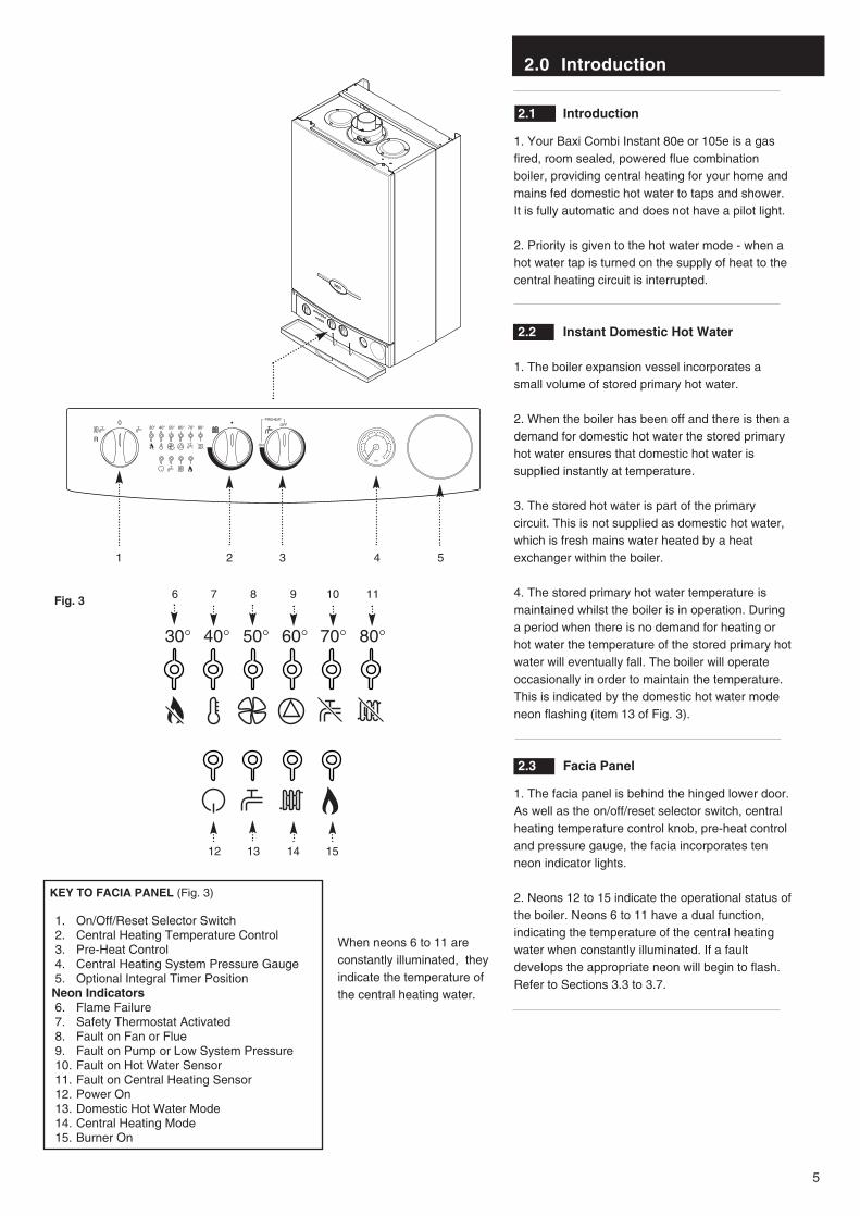
2.3 Facia Panel
1. The facia panel is behind the hinged lower door.As well as the on/off/reset selector switch, centralheating temperature control knob, pre-heat controland pressure gauge, the facia incorporates tenneon indicator lights.
2. Neons 12 to 15 indicate the operational status ofthe boiler. Neons 6 to 11 have a dual function,indicating the temperature of the central heatingwater when constantly illuminated. If a faultdevelops the appropriate neon will begin to flash.Refer to Sections 3.3 to 3.7.
30° 40° 50° 60° 70° 80°2
1
0 4
3
bar
OFF
ON
PREHEAT
Fig. 3
30° 40° 50° 60° 70° 80°
1. On/Off/Reset Selector Switch2. Central Heating Temperature Control3. Pre-Heat Control4. Central Heating System Pressure Gauge5. Optional Integral Timer PositionNeon Indicators6. Flame Failure7. Safety Thermostat Activated8. Fault on Fan or Flue9. Fault on Pump or Low System Pressure10. Fault on Hot Water Sensor11. Fault on Central Heating Sensor12. Power On13. Domestic Hot Water Mode14. Central Heating Mode15. Burner On
321 4 5
6 7 8 9 10 11
12 13 14 15
KEY TO FACIA PANEL (Fig. 3)
When neons 6 to 11 areconstantly illuminated, theyindicate the temperature ofthe central heating water.
3.0 Operating the Boiler
6
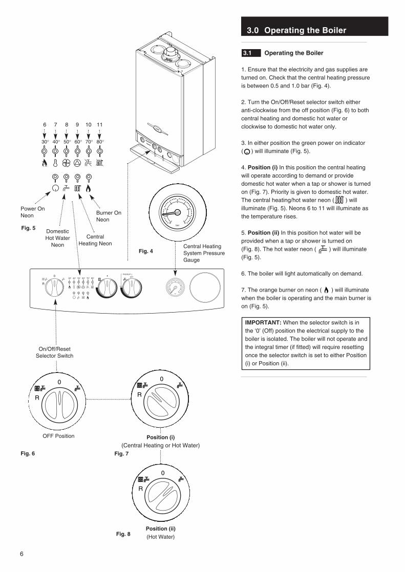
3.1 Operating the Boiler
1. Ensure that the electricity and gas supplies areturned on. Check that the central heating pressureis between 0.5 and 1.0 bar (Fig. 4).
2. Turn the On/Off/Reset selector switch eitheranti-clockwise from the off position (Fig. 6) to bothcentral heating and domestic hot water orclockwise to domestic hot water only.
3. In either position the green power on indicator ( ) will illuminate (Fig. 5).
4. Position (i) In this position the central heatingwill operate according to demand or providedomestic hot water when a tap or shower is turnedon (Fig. 7). Priority is given to domestic hot water.The central heating/hot water neon ( ) willilluminate (Fig. 5). Neons 6 to 11 will illuminate asthe temperature rises.
5. Position (ii) In this position hot water will beprovided when a tap or shower is turned on (Fig. 8). The hot water neon ( ) will illuminate(Fig. 5).
6. The boiler will light automatically on demand.
7. The orange burner on neon ( ) will illuminatewhen the boiler is operating and the main burner ison (Fig. 5).
IMPORTANT: When the selector switch is inthe ‘0’ (Off) position the electrical supply to theboiler is isolated. The boiler will not operate andthe integral timer (if fitted) will require resettingonce the selector switch is set to either Position(i) or Position (ii).
30° 40° 50° 60° 70° 80°2
1
0 4
3
bar
OFF
ON
PREHEAT
Position (ii)
(Hot Water)
Fig. 7
Fig. 8
OFF Position
Fig. 6
Fig. 5
Fig. 4
2
1
0 4
3
bar
Power On Neon Burner On
Neon
Central HeatingSystem PressureGauge
Position (i)
(Central Heating or Hot Water)
On/Off/ResetSelector Switch
Central Heating Neon
DomesticHot Water
Neon
30° 40° 50° 60° 70° 80°
6 7 8 9 10 11

3.0 Operating the Boiler
7
3.2 Temperature Control
1. Central Heating: The central heating hot waterflow temperature can be adjusted between 30° C(± 5° C) minimum and 85° C (± 5° C) maximum.
2. Turn the control knob clockwise to increase thetemperature (Fig. 9).
3. In normal winter usage we recommend that thecentral heating temperature be set at maximum.
4. Domestic Hot Water Pre-Heat: To enjoyoptimum performance of the boiler the pre-heatcontrol should be set fully clockwise to the ONposition (Fig. 10). When there is a demand for hotwater it will be supplied at approximately 65° Cinstantaneously.
5. Turning the control 15° clockwise from the OFFposition will activate the pre-heat feature. Hotwater will be supplied at approximately 35° Cinstantaneously.
6. To increase the temperature turn the controlfurther clockwise. For example, when set 90°clockwise the boiler will supply hot water atapproximately 44° C instantaneously. At aposition 180° from clockwise (i.e. straight down)the hot water will be supplied at 52° Cinstantaneously.
7. When the control is set anywhere between 15°clockwise from the OFF position and the ONposition, the pre-heat feature will operate.
8. With the control in the OFF position (Fig. 11)the pre-heat feature will not operate. Hot waterwill be supplied at approximately 50° C.
9. The pre-heat feature will function with theselector switch in either operating position. This isindicated by the domestic hot water mode neonflashing (Fig. 12).
10. The flow rate can be reduced down to as lowas 2.5 litre/min. The boiler will still recognise theneed to heat the water.
3.3 Flame Failure Reset
1. The red flame failure neon ( ) will illuminatein the event of the burner failing to light, or whenincomplete lighting of the burner occurs (Fig. 12).
2. Turn the selector switch fully anti-clockwiseagainst the spring pressure to the reset position(R) and release (Fig. 13). Set the selector to therequired position to light the boiler.
3. If the flame failure light illuminates repeatedly afault is indicated. Your installer or ServiceEngineer should be called as soon as possible.
OFF
ON
PREHEAT
Domestic Hot WaterPre-Heat Control
ON Position
Fig. 9
Central HeatingTemperature Control
Fig. 10
Reset Position
Fig. 13
30° 40° 50° 60° 70° 80°
Flame FailureNeon
Fig. 12
OFF
ON
PREHEAT
Fig. 11
Domestic Hot WaterPre-Heat Control
OFF Position
Domestic HotWater Neon

3.0 Operating the Boiler
8
3.4 Safety Thermostat
1. Your Baxi Combi Instant 80e or 105e is fittedwith an additional safety device, which shutsdown the boiler in the event of the system or theboiler overheating. The safety thermostat neon ( ) will light in this instance (Fig. 14).
2. To reset: Turn the selector fully anti-clockwiseagainst the spring pressure to the reset position(R) and release (Fig. 15). Set the selector to therequired position to light the boiler.
3. If the safety thermostat operates repeatedly,causing boiler shutdown, a fault is indicated. Yourinstaller or Service Engineer should be contactedas soon as possible.
3.5 Air Flow Monitor
1. The boiler is fitted with an air pressure sensingdevice. This monitors the flue system.
2. If the neon illuminates ( ) it indicates thatthe flue or flue terminal is blocked or obstructed insome way, or that there is an internal fault. If thereis no external blockage of the flue terminal thatcan be easily removed contact your installer orService Engineer (Fig. 14).
3.6 Pump Fault or Low Pressure
1. The neon ( ) will illuminate if the circulatingpump is faulty or the system pressure dropsbelow the minimum requirement (Fig. 14).
2. Check the pressure gauge as described inSection 3.9. If the pressure is in the normal range,a pump fault is indicated. Contact your installer orService Engineer to determine the nature of thefault.
3.7 Sensor Fault
1. When the ( ) or ( ) neon is illuminated afault on the hot water or central heatingtemperature sensor is indicated (Fig. 14). Contactyour installer or Service Engineer.
3.8 Pump Protection
1. With the selector switch in either Position (i) orPosition (ii) (Figs. 16 & 17) the pump willautomatically operate for 1 minute in every 24hours to prevent sticking.
30° 40° 50° 60° 70° 80°
Air Flow Monitor Neon
Pump/LowPressure Neon
Sensor Fault Neons
Fig. 14
Fig. 16
Fig. 17
SafetyThermostatNeon
Reset Position
Fig. 15
3.0 Operating the Boiler
9
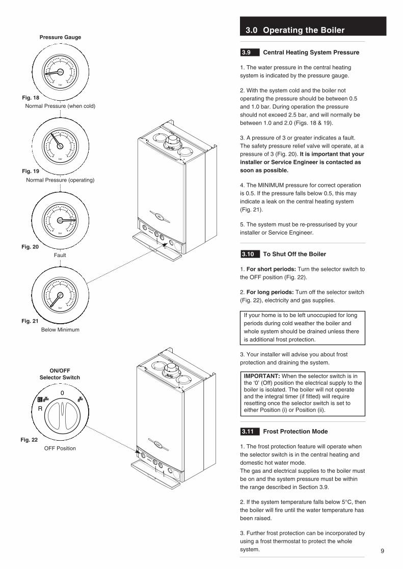
3.9 Central Heating System Pressure
1. The water pressure in the central heatingsystem is indicated by the pressure gauge.
2. With the system cold and the boiler notoperating the pressure should be between 0.5and 1.0 bar. During operation the pressureshould not exceed 2.5 bar, and will normally bebetween 1.0 and 2.0 (Figs. 18 & 19).
3. A pressure of 3 or greater indicates a fault.The safety pressure relief valve will operate, at apressure of 3 (Fig. 20). It is important that yourinstaller or Service Engineer is contacted assoon as possible.
4. The MINIMUM pressure for correct operationis 0.5. If the pressure falls below 0.5, this mayindicate a leak on the central heating system(Fig. 21).
5. The system must be re-pressurised by yourinstaller or Service Engineer.
3.10 To Shut Off the Boiler
1. For short periods: Turn the selector switch tothe OFF position (Fig. 22).
2. For long periods: Turn off the selector switch(Fig. 22), electricity and gas supplies.
If your home is to be left unoccupied for longperiods during cold weather the boiler andwhole system should be drained unless thereis additional frost protection.
3. Your installer will advise you about frostprotection and draining the system.
IMPORTANT: When the selector switch is inthe ‘0’ (Off) position the electrical supply to theboiler is isolated. The boiler will not operateand the integral timer (if fitted) will requireresetting once the selector switch is set toeither Position (i) or Position (ii).
3.11 Frost Protection Mode
1. The frost protection feature will operate whenthe selector switch is in the central heating anddomestic hot water mode.The gas and electrical supplies to the boiler mustbe on and the system pressure must be withinthe range described in Section 3.9.
2. If the system temperature falls below 5°C, thenthe boiler will fire until the water temperature hasbeen raised.
3. Further frost protection can be incorporated byusing a frost thermostat to protect the wholesystem.
2
1
0 4
3
bar
2
1
0 4
3
bar
2
1
0 4
3
bar
2
1
0 4
3
bar
ON/OFFSelector Switch
OFF Position
Fig. 22
Normal Pressure (when cold)
Normal Pressure (operating)
Fig. 18
Fault
Fig. 19
Below Minimum
Fig. 20
Fig. 21
Pressure Gauge

4.0 Clearances and Check List
10
4.1 Clearances around the Boiler(Figs. 23 & 24)
1. The minimum clear spaces needed around theboiler measured from the casing are as follows:
Top - 200mmBottom - 200mmBoth sides - 5mmFront - 5mm (In Operation)
- 450mm (For Servicing)
2. These areas must not be obstructed in anyway. Blocking the clearance spaces mayresult in the boiler overheating and damagemay occur.
3. The gas burning compartment of your boiler iscompletely sealed from the room in which it isfitted. Products from the combustion of gas arevented to the outside through the flue terminalwhich must be kept free from obstruction as thiswould interfere with the correct operation of theboiler.
4. The boiler may be installed in a cupboard ifthese minimum clearances are kept. Thecompartment should be large enough to housethe boiler and ancillary equipment only.
5. IT SHOULD NOT BE USED AS A STORAGECUPBOARD.
4.2 Check List
1. If a fault develops, or is suspected, call yourinstaller or Service Engineer as soon as possible.
2. Go through the following check list before youmake contact.
a) Is the electricity supply on ?b) Is the selector switch on (giving a green
“Power ON” neon) and set for both Central Heating and Domestic Hot Water ?
c) Is the red “Flame Failure” neon lit ? Turn the On/Off/Reset selector fully anti- clockwise.
d) Is the gas supply on ?e) Is the mains water supply turned on ?f) Is the system pressure correct ?g) Are the boiler temperature controls set high
enough ?h) Is the time clock (if fitted) calling for central
heating ?i) Is the room thermostat (if fitted) set high
enough ?j) Are the radiator valves open ?
200mm Min
780mm
450mm
200mm Min
5mm Min5mm Min
5mm
450mm Min
For ServicingPurposes
Fig. 23
Fig. 24In Operation

5.0 Cleaning, Spares & Guarantee
11
5.1 Cleaning the Outercase
The painted panels should be wiped with a dampcloth and then dried completely. DO NOT USEABRASIVE CLEANING AGENTS.
5.2 Spare Parts
IMPORTANT - Only a competent personshould be used to service or repair this boiler.
1. Any repairs to the boiler will usually be theresponsibility of the Installer during theguarantee period after which spare parts may beobtained through approved Baxi stockists ifrequired.
2. Quote the appliance name, model numberand where possible the part number whenordering spares. A parts list is included in theInstallation and Servicing Instructions.
3. The name, model number and serial numbercan be found on the information label on theback of the hinged lower door.
5.3 Guarantee
1. Your Baxi Combi Instant 80e or 105e isdesigned and produced to meet all the relevantStandards.
2. Baxi provide a 12 month guarantee on theboiler. The guarantee operates from the dateinstallation is completed for the customer who isthe original user.
3. To maximise the benefit from our guaranteewe urge you to return the reply-paid guaranteeregistration.
4. This does not in any way prejudice your rightsat Common Law. Such rights between thecustomer and the installer or supplier from whomthe unit was purchased remain intact.
Any component or part which becomesdefective during the guarantee period as aresult of faulty workmanship or materialwhilst in normal use will be repaired orreplaced free of charge.
Comp No 248742 - Iss 2 - 4/03
921.892.2BAXI POTTERTONA Trading Division of Baxi Heating UK LtdBrownedge Road Bamber Bridge Preston Lancashire PR5 6SNAfter Sales Service 08706 096 096 Technical Enquiries 08706 049 049Website www.baxi.co.uk
company
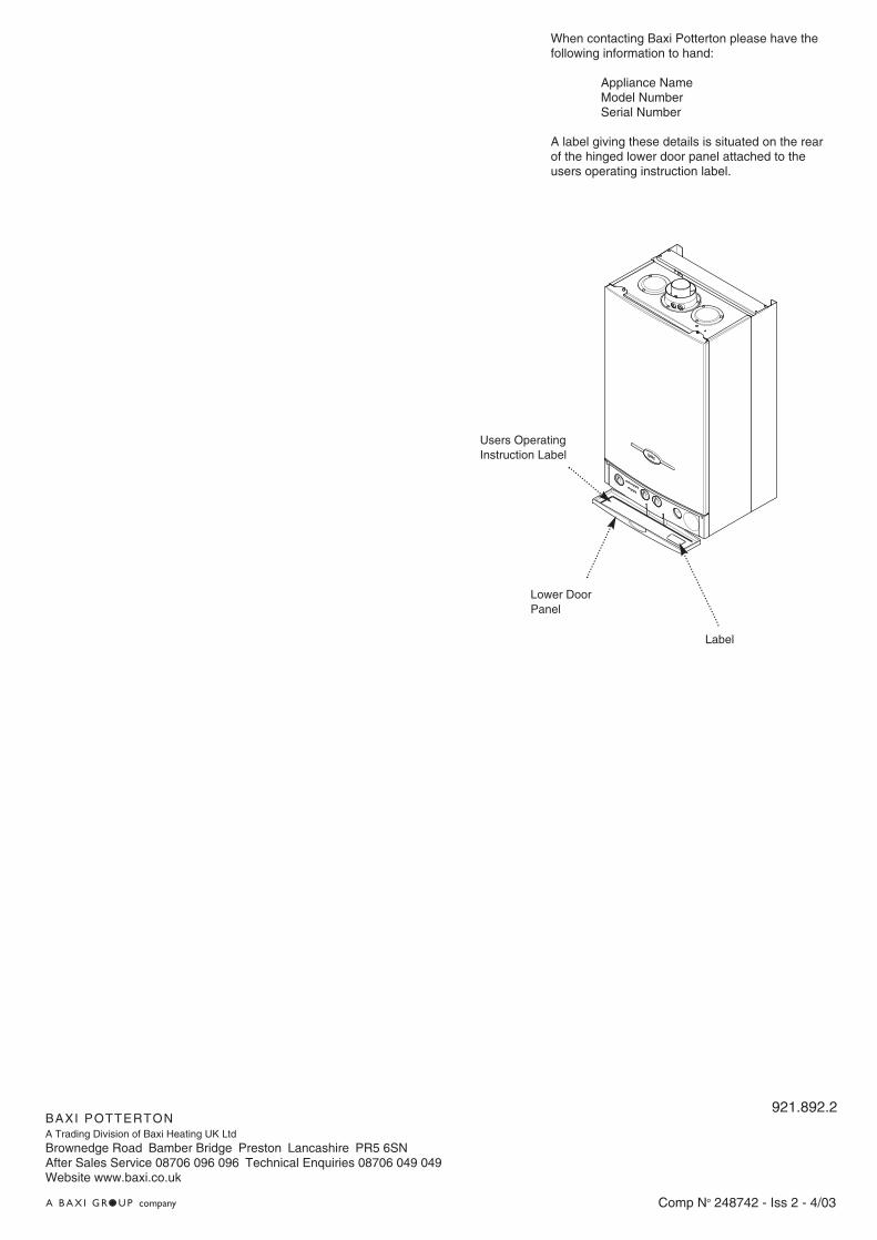
When contacting Baxi Potterton please have thefollowing information to hand:
Appliance NameModel NumberSerial Number
A label giving these details is situated on the rearof the hinged lower door panel attached to theusers operating instruction label.
Label
Lower DoorPanel
Users OperatingInstruction Label