user's manual ver. 1 - istcgroup.com · 2f sakurai building 2 8 19 fukagawa koto ku tokyo,...
TRANSCRIPT

MotionPro HS-1MotionPro HS-2MotionPro HS-4
User's ManualVer. 1.12

MotionPro HS Series User’s Manual
Table of Contents
Contact Information............................................................................................................................. iv
Precautions .............................................................................................................................................vCleaning the Sensor.............................................................................................................................................................................. vLaser ........................................................................................................................................................................................................... vStorage ...................................................................................................................................................................................................... v
System Overview................................................................................................................................... 1System Components ............................................................................................................................................................................ 2System Accessories ............................................................................................................................................................................... 2Software Developer’s Kit..................................................................................................................................................................... 2
Installing the MotionPro System.......................................................................................................... 3Minimum Computer Requirements................................................................................................................................................ 3Package contents .................................................................................................................................................................................. 3 Software Installation............................................................................................................................................................................ 4Hardware Installation........................................................................................................................................................................... 5Camera Lens Adapters......................................................................................................................................................................... 5
MotionPro Central Standalone Program ............................................................................................. 6Open Camera Wizard ........................................................................................................................................................................... 7MotionPro Central Menu Structure ................................................................................................................................................. 8File Menu .................................................................................................................................................................................................. 9
Initialize a camera window........................................................................................................................................................ 9Open File Images .......................................................................................................................................................................... 9
Save Images...........................................................................................................................................................................................10Edit Menu ...............................................................................................................................................................................................11Image Menu...........................................................................................................................................................................................12Color Map Adjustment for Black and White Imagesq ............................................................................................................13Brightness, Contrast, Gamma Correction ...................................................................................................................................14
Brightness and Contrast Adjustment ..................................................................................................................................14Gamma Correction .....................................................................................................................................................................15
Filter Menu .............................................................................................................................................................................................16Create a User-defined Filter .............................................................................................................................................................17Camera Menu........................................................................................................................................................................................18Camera Control ....................................................................................................................................................................................18Camera Configuration .......................................................................................................................................................................19
Region of Interest (ROI).............................................................................................................................................................20Record Configuration.........................................................................................................................................................................21
Advanced Acquisitions Configuration ................................................................................................................................23Saving Acquired Images....................................................................................................................................................................25Color Configuration ............................................................................................................................................................................27
Automatic White Balance.........................................................................................................................................................28Advanced Camera Configuration in Camera Menu ................................................................................................................29
Noise Calibration Wizard Options.........................................................................................................................................30Color Balance Adjustment.......................................................................................................................................................31
Playback Controls ................................................................................................................................................................................32Frame by Frame Review ...........................................................................................................................................................32Playback Speed and Playback Settings...............................................................................................................................32
Playback Menu......................................................................................................................................................................................33View Menu..............................................................................................................................................................................................34
Thumbnail Viewer and Configuration.................................................................................................................................35Tools Menu.............................................................................................................................................................................................36
General Options...........................................................................................................................................................................37Camera Options...........................................................................................................................................................................38Frame Info Options.....................................................................................................................................................................39
Redlake 1/17/05 i

MotionPro HS Series User’s Manual
Miscellaneous...............................................................................................................................................................................40Histogram ......................................................................................................................................................................................41Focus Line Tool ............................................................................................................................................................................42Timing Hub Control Tool..........................................................................................................................................................44
Window menu ......................................................................................................................................................................................47Help Menu..............................................................................................................................................................................................47
Camera Information...................................................................................................................................................................47
Frame Synchronization and Event Triggering.................................................................................. 48Internal Mode........................................................................................................................................................................................48External Mode.......................................................................................................................................................................................49Start/Stop Mode...................................................................................................................................................................................50Rate Switch Mode................................................................................................................................................................................51Pulse Mode.............................................................................................................................................................................................52Overview of External Sync and Event Triggering.....................................................................................................................53
Record Modes and Trigger Configuration .........................................................................................................................53 Change the Sync and Trigger Source .................................................................................................................................54Change the Sync and Trigger Configuration ....................................................................................................................54Circular or BROC Record Mode and Trigger Configuration .........................................................................................55Exposure Modes ..........................................................................................................................................................................56
Triggering the Camera and Synchronizing with Strobe Illumination ..............................................................................57Synchronizing via the leading edge of a pulse event (Single exposure)................................................................57Synchronizing via the trailing edge of a pulse event (Single exposure).................................................................58Synchronizing and Controlling the Exposure with an Input Pulse ...........................................................................59Synchronizing in Dual Exposure Mode...............................................................................................................................59
Appendix A Product Specifications ................................................................................................... 61Frame Storage Capacity ....................................................................................................................................................................62
Appendix B Image Formats ................................................................................................................ 63TIFF Format ............................................................................................................................................................................................63Bitmap Format......................................................................................................................................................................................63PNG Format............................................................................................................................................................................................63AVI Format..............................................................................................................................................................................................64BLD Format ............................................................................................................................................................................................64MPEG Format ........................................................................................................................................................................................64Multi-page Raw Format (MRF) ........................................................................................................................................................64Multi-page Compressed Format (MCF) .......................................................................................................................................65
Appendix C Spatial filtering 67Linear filters (Convolution filters) ..................................................................................................................................................67Linear sharpening filters ...................................................................................................................................................................68
Laplacian Filter .............................................................................................................................................................................69Linear Smoothing filters....................................................................................................................................................................69Nonlinear filters ....................................................................................................................................................................................70Adding noise to images ....................................................................................................................................................................70
Appendix D Look Up Table (LUT) Transformations.......................................................................... 71
Appendix E Color Filter Arrays (CFA) ................................................................................................. 73
Redlake 1/17/05 ii

MotionPro HS Series User’s Manual
Redlake 1/17/05 iv
1. Contact Information
Send comments regarding the manual to [email protected].
Copyright 2004 Redlake MASD, LLC
The information in this manual is for information purposes only and is subject to change without notice. Redlake MASD, LLC makes no warranty of any kind with regards to the information contained in this manual, including but not limited to implied warranties of merchantability and fitness for a particular purpose. Redlake MASD, LLC shall not be liable for errors contained herein nor for incidental or consequential damages from the furnishing of this information. No part of this manual may be copied, reproduced, recorded, transmitted or translated without the express written permission of Redlake MASD, LLC.
Manual Ver. 1.12
December 2004
Americas:
Find a authorized reseller in your state
Call: 1-800-462-4307
858-481-8182
Website: www.redlake.com [email protected]
Europe, Middle East and Africa:
Roper Scientific BV
Ir. D.S. Tuijnmanweg 10
4131 PN Vianen
Netherland
Telephone: +31-347-32-4989
Fax: +31-347-32-4979
Asia/Pacific:
Redlake
10 Eunos Road 8 #12-06
Singapore Post Centre 408600
Singapore
Telephone: +65-6293-4758
Fax: +65-6293-3307
Japan:
Nippon Roper
2F Sakurai Building
2 8 19 Fukagawa Koto Ku
Tokyo, 135-0033, Japan
Telephone: +81-3-5639-2770
Fax: +81-3-5639-2775

MotionPro HS Series User’s Manual
Redlake 1/17/05 v
2. Precautions
2.1. Cleaning the Sensor Clean the optical surfaces with filtered, compressed air and glass cleaner or distilled water. Use a cotton swab or lens paper. Do not use alcohol or other solvents as these may damage the optical coating and cements.
2.2. LaserDo not focus a laser beam on the sensor directly or by reflection, it can cause permanent damage to the sensor. Any laser powerful enough to produce localized heating at the surface of the sensor will cause damage, even if the camera power is off. Laser-damaged sensors are NOT covered by the warranty.
2.3. StorageUse the original shipping carton when transporting the MotionPro System. If you must frequently ship your imager, you may wish to purchase a carrying case. Please contact your Redlake representative for details.

MotionPro HS Series User’s Manual
3. System Overview
Redlake's MotionPro HS series of high-speed CMOS cameras combine excellent resolution to frame rate performance, along with the advanced features you require for accurate high-speed motion analysis on your laptop or desktop computer. Whether you need the value of the MotionPro HS-1, delivering 650 fps at 1280 x 1024 resolution, the added performance of the MotionPro HS-2 at over 1200 fps at 1280 x 768, or the blazing speed of the MotionPro HS-4 at over 5000 fps at 512 x 512, there is a MotionPro HS Series camera that is perfect for your application.
The cameras feature plug-and-play installation and high-speed transfers to a computer with a USB 2.0 interface. Also, the readily accessible trigger input, and output signals quickly integrate the camera with illumination sources, such as lasers or strobe lights. Provided with the camera is the MotionPro Central camera control software which includes a stand-alone application, TWAIN driver, MATLAB and LabVIEW plug-ins, as well as a Software Developer’s Kit (SDK) for customized application development. The SDK includes the complete C++ source code of image acquisition program examples to help integrate camera controls in custom applications.
Feature Highlights:
• Range of performance options from 1280 x 1024 at 650 fps to 512 x 512 at 5145 fps
• Mac and PC compatible with LabVIEW™ and MATLAB® plug-ins
• USB 2.0 interface for simple integration
• One microsecond frame interval in double exposure mode for capture and analysis of high-speed events
• Configurable Region of Interest for selection of precise field of view to maximize performance
Practical Applications:
• Research, development and test
• Production line diagnostics
• Range, aerospace and ballistics
• Mechanical component test
• Particle Image Velocimetry (PIV)
Redlake 1/17/05 1

MotionPro HS Series User’s Manual
3.1. System ComponentsMotionPro Camera Models (HS-1, HS-2, HS-4): high-speed camera featuring a CMOS sensor.
Digital Interface: a USB 2.0 (480 Mb/s) cable provides data and control signals to and from the camera. Use the USB 2.0 port on a personal computer or laptop to connect to the camera.
Power Source: provides external power to the camera.
Trigger and Synchronization Cable: the camera has three BNC connectors for input and output of trigger and synchronization signals. These signals are CMOS level, and provide a means to synchronize the camera with an external clock, or trigger it with relationship to an event. The synchronization signals are generated for every image frame produced.
MotionPro Central Camera Control Software: operates in Windows 2000 or Windows XP environments. It plugs into LabVIEW and MATLAB, and provides an SDK for customized application development.
Optical Interface: the standard interface is C-mount. C-to F and Canon mount converters are available upon request.
3.2. System AccessoriesHS Timing Hub: USB digital interface, integrated control software with 8 outputs and 2 inputs
USB Repeater: for up to 15m.
3.3. Software Developer’s KitThe software components included in the MotionPro Central Software Development Kit are:
• Stand-alone image acquisition application
• SDK modules with example source code in MSVC++ and VB
• TWAIN driver
• Plug-in for LabVIEW™
• Plug-in for MATLAB™
The MotionPro Central SDK modules provide an API interface to develop applications to operate the camera and access all the camera capabilities using a programming language such as C++ and Java. A C/C++ header file is included in the SDK. A Visual Basic module is also included in the SDK .
The MotionPro driver is a DLL that resides in the System 32 directory. A Visual C++ 6.0 sub library is provided. Most other compilers can create a sub library for Dells. The DLL uses Windows standard calling conventions (_stdcall).
Redlake 1/17/05 2

MotionPro HS Series User’s Manual
4. Installing the MotionPro System
This section specifies the minimum recommended computer requirements and provides the procedures to install the camera, camera cable, power supply, I/O cable, and software.
4. 1. Minimum Computer RequirementsThe minimum system requirements are as follows:
• Operating System: Windows 2000 or XP.
• Processor: Pentium III or equivalent with 500 MHz processor.
• RAM: 256 MB.
• USB-2 port: high speed USB port that is NOT shared with other devices.
• Monitor: Capable of 1024 x 768 or greater resolution.
• Hard Drive: 40 GB or greater hard drive (recommended).
• Additional Equipment: CDR drive (recommended).
4. 2. Package contentsBefore beginning the installation process, check that the following items are present in your shipment. If you are missing any of the items listed below, contact your sales representative.
• Camera
• I/O USB 2.0 cable
• CD-ROM of MotionPro Central camera control software and documentation
• Power supply with 5-pin cable
• MotionPro Central Quick Start Guide
NOTE: Install the software before connecting the camera to the computer. The software must be installed for the computer to recognize the camera.
Redlake 1/17/05 3

MotionPro HS Series User’s Manual
•
•
4. 3. Software InstallationBefore setting up the camera hardware, install the software provided on the MotionPro CD. The installation process will install the camera drivers, camera control software and a MotionPro Central icon on the desktop.
Windows 2000/XP
Before installing MotionPro Central, make sure that the computer has Windows 2000 or XP installed as the operating system.
1. Log on to the computer with a username and password that have ADMINISTRATIVE PRIVILEGES.
2. Insert the MotionPro CD into the computer’s CD-ROM drive. If the computer is config-ured for AUTORUN, the installer will run automatically. If not, click on the Windows Start button. Select Run from the menu. Use the Browse button to locate the SETUP.EXE file on the MotionPro CD and click on the OK button.
3. Follow the on-screen instructions.
4. Select Install from the menu and follow the on-screen instructions.
5. Click on the check boxes to install the software plug-in components. Components include:
• Twain Driver
• LabVIEW VIs
• MATLAB Interface
6. EXIT when the installation is complete and restart the computer.
NOTE: connect the camera to the computer before connecting the camera to the power source.
Redlake 1/17/05 4

MotionPro HS Series User’s Manual
4. 4. Hardware InstallationAt 24 VDC, 3 Amp supplies the camera with the necessary power. This power supply unit is included with the camera system package. All communication and data transfer with the host computer is done via the USB-2 interface. This interface requires a single cable, which is also supplied with the camera package. External triggering and synchronization are done via the BNC connectors. Triggering and synchronization are performed with a TTL pulse.
1. Connect the USB 2.0 cable to an available USB 2.0 port on the computer.
2. Connect the other end of the USB 2.0 cable to the back of the camera.
3. Connect the camera to the power source.
4. Turn the camera’s ON/OFF switch to the ON position and wait a few seconds for the camera to initialize itself.
5. Click on the Yes or Continue Anyway button when prompted by the Windows 2000 or XP operating system to proceed with the installation.
6.
7.
8.
4. 5. Camera Lens AdaptersThe camera is supplied with a standard C-mount. Alternatively, a C to F mount adapter is available to interface with F-mount (Nikon type) lenses. Use Nikon lenses with a tilt/shift capability when imaging at an angle. As an option, mounting hardware for tilt/shift lenses by Canon are also available. Please contact your Redlake sales representative for ordering information.
Figure 4.1: MotionPro HS back panel
NOTE: Use an USB 2.0 port on the computer. USB 1.0 will not support the operation of the camera.
Redlake 1/17/05 5

MotionPro HS Series User’s Manual
5. MotionPro Central Standalone Program
This application allows you to acquire, save, playback image records, and control the camera in Single or Double Exposure modes. It also allows you to retrieve file images from previous acquisitions for display and further manipulation.
Figure 5.1: MotionPro Central Start up Menu
Redlake 1/17/05 6

MotionPro HS Series User’s Manual
5.1. Open Camera WizardAfter the computer recognizing the hardware, the Open Cameras Wizard displays. Follow the on-screen procedures to initialize the camera.
Figure 5.2: Open Cameras Wizard
Redlake 1/17/05 7

MotionPro HS Series User’s Manual
5.2. MotionPro Central Menu StructureThe MotionPro main toolbar contains the following options:
File, Edit, Image, Filter, Camera, View, Tools, Window and Help. The application also includes a docked dialog bar on the right side. The Docked Dialog Bar has the main operational controls of the camera and they are grouped by function: Camera Configuration, Image Recording Configuration, Color Configuration (for color cameras only) and Playback controls for acquired images.
Figure 5.3: MotionPro Central Main Display
Redlake 1/17/05 8

MotionPro HS Series User’s Manual
5.3. File MenuThe File menu contains the following options:
• Open previously acquired and filed images.
• Open the camera window.
• Save images on the computer disk system and close windows.
• Ability to select from a list of the five most recently displayed images.
5.3.1. Initialize a camera window From the main menu select File > Open > Camera.
5.3.2. Open File ImagesFrom the main menu select File > Open > Images.
Figure 5.4: File Menu
Redlake 1/17/05 9

MotionPro HS Series User’s Manual
5.4. Save ImagesEach acquired sequence can be opened and saved in a different format.
1. From the main menu select File > Save.
2. Select the desired folder.
3. Type the image name, the image format and the sequence rate.
4. Also a subset of the sequence can be saved. Select a region of interest by pressing the Edit button.
5. Select the Reset Frames Numbering option to change the start frame index to positive or change the Image Step.
Figure 5.5: Save Image Files
Redlake 1/17/05 10

MotionPro HS Series User’s Manual
5.5. Edit MenuThe Edit menu contains Undo and Redo for filtering and LUT (Look up Table) operations. It also has a Go To... function for jumping to a particular frame in a sequence.
Figure 5.6: Edit drop-down list
Redlake 1/17/05 11

MotionPro HS Series User’s Manual
5.6. Image MenuThe Image menu contains the LUT operations. It also allows flipping and rotating of the image.
If the Camera window is open and the Thumbnails bar is in use, the Thumbnails Cfg... option displays for Thumbnail view configuration options. For more information, refer to the Thumbnails topic.
If an image sequence is open, the Image menu has an Image Info option for displaying the width, height and pixel depth of the image.
The Adjust submenu has controls for the following:
• Color Map for colorizing black and white images
• Brightness and Contrast
• Gamma correction
• Inverting
• Equalizing images.
The Lookup Table submenu has controls for the following LUT transformations including:
• Linear
• Equalize
• Logarithmic
• Exponential
• Gate For further information on LUTs, please refer to the Appendix.
Figure 5.7: Camera Image drop-down list
NOTE: Brightness and Contrast, Gamma, LUT, Invert and Histogram Equalize are intensity operations. Any intensity operation can be applied to the image only once. If you apply a LUT to the current image and then select Brightness and Contrast, the preview window will show the original image without any LUT modification.
Redlake 1/17/05 12

MotionPro HS Series User’s Manual
5.7. Color Map Adjustment for Black and White ImagesThe Color Map has controls for displaying black and white images in color using a pre-loaded, user-defined color scheme.
1. Select Image from the main toolbar.
2. Select Adjust from the Image drop-down list.
3. Select Color Map.
4. Select Base Color Map from the drop-down list.
5. Change the RGB values and Point Index.
6. Click redistribute Control Points.
7. Click OK to change the image.
Figure 5.8: Color Map
Redlake 1/17/05 13

MotionPro HS Series User’s Manual
5.8. Brightness, Contrast, Gamma Correction The Brightness and Contrast Adjustment and the Gamma Correction provide previews of the altered image in a thumbnail. The thumbnail can also be magnified for detailed inspection.
5.8.1. Brightness and Contrast Adjustment1. Select Image from the main toolbar.
2. Select Adjust from the Image drop-down list.
3. Select Brightness and Contrast.
4. Use the up and down arrow buttons to adjust the values.
5. Use the Zoom drop down list to inspect the image details.
Figure 5.9: Brightness and Contrast Adjustment
Redlake 1/17/05 14

MotionPro HS Series User’s Manual
5.8.2. Gamma Correction1. Select Image from the main toolbar.
2. Select Adjust from the Image drop-down list.
3. Use the Gamma Correction slider to change the value.
4. Use the Zoom drop-down list to inspect the image details.
Figure 5.10: Gamma Correction
Redlake 1/17/05 15

MotionPro HS Series User’s Manual
5.9. Filter MenuThe filter menu has several pre-set filters as well as user defined filters. A preview window with an image thumbnail is available and includes the filter kernel options dialog box.
From the main toolbar select Filter > the desired filter submenu from the following:
• Sharpening filters: Laplacian, Prewitt and Sobel.
• Smoothing filters: Average, Gaussian, Smooth, Median.
• Effect filters: Minimum, Maximum, Uniform Noise, Gaussian Noise, Erode, Dilate, Open, Close.
Figure 5.11: Filter drop down list
Figure 5.12: Filter dialog box with Kernel Display
Redlake 1/17/05 16

MotionPro HS Series User’s Manual
5.10. Create a User-defined FilterThe User Filter utility has the flexibility to apply a custom filter and save the kernel for future use. The filter kernel size, anchor point and image divisor are custom configurable.
Once a custom filter has been created and saved, the user-defined filter is added to the Filter drop-down list.
1. Select Filter from the main toolbar.
2. Select User from the drop-down list.
Figure 5.13: Edit User Filter dialog box
Redlake 1/17/05 17

MotionPro HS Series User’s Manual
5.11. Camera Menu The Camera Menu on the main toolbar offers an alternative to using the buttons and dialog box provided by the Docked Dialog menu including the following functions:
1. Record
2. Stop
3. Play
4. Playback
5. Edit Region of Interest (ROI)
5.12. Camera ControlThe Camera Control Tab at the top of the Docked Dialog menu has camera control functions including the following:
• Record
• Live play of images (continuous)
• Trigger
• Stop.
Figure 5.14: Camera Drop-down list
Figure 5.15: Camera Control Tab
Redlake 1/17/05 18

MotionPro HS Series User’s Manual
5.13. Camera ConfigurationUse the Camera Tab on the Docked Dialog menu at the right of the image to configure the camera. The configuration options are as follows:
Sensor GainUse the Sensor Gain drop-down list to select a Gain value ranging from: No Gain to Gain 3.
Reset
Click the Reset button if a Device I/O Control Error appears error condition. The Reset button restores the camera from the error condition
RateUse the Rate (Hz) drop-down list to select a new Frame Rate value. If the current exposure is too large for the selected rate, the program automatically adjusts it to an acceptable value.
ExposureUse the f-stop buttons to select a new Exposure value. The value is displayed in microseconds.
BinningUse the Binning drop-down list to select a new value from 1x1 to 4x4. Pixels can be grouped to form a larger pixel, which results in added SNR and sensitivity. When this parameter is changed, the Region of Interest (ROI) is reset. The control is disabled when the camera is in live mode.
Pixel DepthUse the Pixel Depth drop-down list to select from the following options: 8-bit (Gray 8) or 10-bit (Gray 16) for monochrome cameras, or 24 bit (RGB) for color cameras.
Live Time OutIf the camera cannot snap a frame during live mode, a time out may occur. Type a new value into the text box to change the duration of the time out. The value is displayed in seconds.
ROIClick on the ROI button to open the ROI dialog, and change the current settings. For more information, see Region of Interest (ROI) topic.
Exposure ModeUse the drop-down list to select either Single or Double exposure mode.
Figure 5.16: Camera Configuration Tab
Redlake 1/17/05 19

MotionPro HS Series User’s Manual
5.13.1. Region of Interest (ROI)To set a region of interest for the image that is less than the total available area of the sensor.
1. Click on the ROI button on the Camera Configuration Tab.
2. From the Edit Region of Interest dialog box, select the ROI by setting the numerical values for its origin and dimensions or by dragging the handles of the red box that highlights the ROI within the sensor area.
Once the ROI is configured only the active portion of the image is acquired and displayed. It is important to note that the maximum framing rate of the camera is inversely proportional to the number of rows in the ROI.
Region of Interest options:
• Resolution: select a resolution from the drop-down list or select User and edit the values in the X Origin, Y Origin, Width and Height text boxes.
• Center ROI: click the button to center the current ROI.
• Reset ROI: click the button to reset to the maximum value.
• Max Rate: displays the maximum acquisition rate for each ROI.
After the ROI is set, the selected region will appear in the main viewing window. To resize the image to the screen area, select the Fit to Window from the main toolbar.
Figure 5.17: Region of Interest dialog box
Redlake 1/17/05 20

MotionPro HS Series User’s Manual
5.14. Record ConfigurationUse the Record tab on the Docked Dialog box at the right of the image to set the record options. Record modeUse the drop-down list and select one of the following options:
• Normal: the camera acquires and stops when the memory segment is filled.
• Circular: the camera acquires and restarts when the memory segment is filled. The camera waits for an event trigger to complete the acquisition.
• BROC (Burst Record on Command): the memory segment is divided into sub-segments; the camera acquires in circular mode in a sub segment. When the event trigger is issued, the camera completes the acquisition and start acquiring in the following sub-segment until the memory segment is filled.
FramesIn the text box edit the number of frames to be recorded to the camera memory in a single acquisition. The values can be set from 1 up to a maximum number depending on the amount of free memory and the number of rows on each frame. Select the number of rows on each frame with the ROI setting.
BROC LengthIf BROC mode is selected, use the text box to type the number of frames of each sub-segment. If the number of frames is 1000 and the BROC length is 100, the camera will acquire 10 sub-segments
Sync Configuration and Event Trigger configuration are separated. Synchronize the camera with a pulse train and simultaneously issue an event trigger from the Trigger In BNC connector.
Frame Sync Use the drop-down list to select Internal or External synchronization source.
Sync CfgWhen the Frame Sync is External, use the Sync Cfg drop-down list to select one of the following options:
• Edge High
• Edge Low
• Pulse High
• Pulse Low
Trigger CfgIn Circular or BROC mode, select from the following event triggers options:
• Edge High
• Edge Low
• Switch Closure
Trigger AdjustWhen the record mode is set to Circular or BROC, the Trigger Adjust controls are active. In this mode the camera acquires the set number of frames before the trigger event (pre-trigger) and the remaining after (post-trigger) the trigger event. Use the slider to adjust the number of pre- and post-trigger frames.
AdvancedUse the Advanced button (wheel icon) to open the Advanced Acquisitions Configuration dialog.
Select Acquisition Use the arrow buttons to select the previous or next acquisition.
Memory Indicator BarThe colored bar depicts the available memory.
Redlake 1/17/05 21

MotionPro HS Series User’s Manual
Figure 5.18: Record Configuration
Redlake 1/17/05 22

MotionPro HS Series User’s Manual
5.14.1. Advanced Acquisitions ConfigurationImage FolderBrowse to the directory of selections for saving acquired images. This is the parent directory for the saved images. Each time the images are recorded a new sub-directory containing the actual image files is created.
Download images after acquisition and stopCheck this box to automatically save the data to the computer’s hard disk after each acquisition.
Download images after acquisition and restart...timesCheck this box to automatically restart the process of saving data to the computer’s hard disk after each acquisition. Use the corresponding text box to type in the number of times to repeat the process.
Acquisition FolderThe first acquisition directory name defaults to Acquis000. Subsequent acquisitions are stored in sequentially numbered directories, (ex. Acquis000, Acquis001, Acquis002…).
NewCreate new acquisition folders to store a new sequence of images using the. Configure all of the parameters independently for each folder.
Image PrefixType the image prefix into the text box.
Frames Use this dialog box to set the number of frames to record.
TimeDisplays the acquisition record time.
File TypeUse the drop-down list to set the image type format for archiving files to the computer.
Memory Size DisplayThe dialog box displays the total memory size in MB and in Mega Pixels. HS-1 models acquire 10 bit images and the pixels are stored in the camera memory in a packed format. Ten pixels are stored in 16 bytes of data, so the size in pixels is the following: pixels = bytes 10/16. Other camera models acquire 8 bit data, so the amount of MB corresponds to the amount of Mega Pixels.
Defrag...Click on the Defrag... button to re-organize the camera memory using the defragmentation utility.
Delete and Delete AllDelete a selected folder or all folders.
Redlake 1/17/05 23

MotionPro HS Series User’s Manual
Figure 5.19: Advanced Acquisitions Configuration
Redlake 1/17/05 24

MotionPro HS Series User’s Manual
5.15. Saving Acquired ImagesThe acquired images stored in different areas of the camera memory can be saved to the computer’s hard drive.
Click the Save button on the main toolbar or select File from the main toolbar > Save Acquisitions…
The program displays a list of the acquisitions. For each acquisition the program displays the following save options and acquisition file information.
Save To FileUse the Save to File drop-down list to save the images and/or the average. Save the images only, the average only or both. Use the From Frame, To frame and Step edit boxes to select the average.
Acquisition FolderThe program creates a new folder for each saved acquisition. Type a new name for the folder directly into the text box.
Image PrefixType a prefix into the text box to change prefix. If the prefix is Img,the images will be saved as “Img000000.”
File TypeUse the drop-down list to select one of the following image formats: TIFF, BMP, PNG, MPT, MRF, MCF and AVI. For more information, See the Appendix.
Output Pixel DepthThe output file pixel depth may be different from the original image's pixel depth in monochrome cameras. Use the drop-down list to select one of the mono or color pixel depths. Bit images with 8 bits can be saved in 8 and 10 bit output files, while 10-bit images can be saved in 8-bit and 10-bit image files. TIFF, PNG, MPT, MCF and MRF support both 8 and 10 bit; BMP and AVI support 8-bit only. Color images are saved in 24-bit RGB format.
From Frame/To Frame/StepType the desired Start Frame Index, Stop Frame Index and Step value directly into the text box. For example, if from=2, to=10 and step=2, only the following frames will be saved: 2, 4, 6, 8 and 10.
Reset Numbering In Circular mode the frame number can be negative; also, the Step may be different from 1. Select the Reset Numbering Option to save images with numbers starting from 0 with Step at 1. Example: start frame is 10, stop frame is 16 and step is 2. If Reset Numbering is unchecked the output file names will be: Img000010, Img000012, Img000014, and Img000016. If it is checked the image names will be: Img000000, Img000001, Img000002, and Img000003.
Redlake 1/17/05 25

MotionPro HS Series User’s Manual
Figure 5.20: Save Acquisitions dialog box
Redlake 1/17/05 26

MotionPro HS Series User’s Manual
5.16. Color ConfigurationIf the camera is color, the Color Tab will display in the Docked Dialog Bar.
The color images acquired from the camera are corrected with a set of coefficients (gains) multiplied to the three color components (Red, Green and Blue). Different light conditions (sun light, halogen, etc.) may require different coefficients.
Light SourceUse the drop-down list to select the light source that best fits the current environment light conditions. Select the User option to manually change the color gains or balance the colors with an automatic balance procedure.
RGB GainsIf the User light source is selected, use the Color Gain sliders to increase or decrease the corresponding color component (red, green or blue). The range is from 0.5 to 2.5.
Gamma, Hue, Saturation, Brightness, ContrastUse the corresponding sliders to increase or decrease the following:
• Gamma correction (0.1 to 4.0)
• Hue (-180 to 180)
• Saturation (0.0 to 3.0)
• Brightness (-1.0 to 1.0)
• Contrast (0.2 to 4.0
Click on the Default button to reset to the original values.
Figure 5.21: Color Tab
Redlake 1/17/05 27

MotionPro HS Series User’s Manual
5.16.1. Automatic White BalanceEdit color gains manually or use the automatic balance procedure.
1. Select the Color tab from the Docked Dialog Bar.
2. Select the User option in the Light Source drop-down list.
3. Press the Target button. A target will appear on the image.
4. Click on the image to move the target. Move the target over a gray, non-saturated area.
5. Click the Apply button.
Figure 5.22: White Balance dialog box
Redlake 1/17/05 28

MotionPro HS Series User’s Manual
5.17. Advanced Camera Configuration in Camera MenuFrom the main toolbar select Camera > Advanced to access operations for editing the Digital to Analog Converters, the Noise Calibration and the Advanced Color Balance.
Select the Digital to Analog Converters to configure the settings for the Analog/Digital conversion on the CMOS sensor chip. Ten converters are available for models HS-1 and HS-2, and 14 converters are available for the model HS-4. Each model has a default value and can be configured with a value from 0 to 3300 mV (CMOS range). The following options are available:
Save...: saves the current configuration in a file (*.DAC) on the computer’s hard disk.
Load...: loads values from the configuration file.
Default: loads the default values.
Figure 5.23: Camera Configuration
Figure 5.24: Digital to Analog Converters dialog box
Redlake 1/17/05 29

MotionPro HS Series User’s Manual
5.17.1. Noise Calibration Wizard Options1. Select Camera from the main toolbar
2. Select Advanced > Noise Calibration.
3. Follow the on-screen instructions. A body cap and color reference card are required to complete the procedure.
Figure 5.25: Noise Calibration Wizard dialog box
Redlake 1/17/05 30

MotionPro HS Series User’s Manual
5.17.2. Color Balance AdjustmentBuild user-defined color tables with the Color Balance procedure.
1. Select Camera from the main toolbar
2. Select Advanced > Color Balance.
3. Use the Color Balance Pad, to create new color schemes (Light Source Tables), edit or delete them.
New Table: Click the button to create a new default diagonal table.Delete Table: Click the button to delete the currently selected table.Default: Click the button to load the default configuration.Color Matrix Units: Click the appropriate button to select either the RGB or YUV color matrix.Reset: Click the button to reset the matrix to the default diagonal configuration. The diagonal matrix has no effect to the image colors.CalibrateCompute the color balance matrix. A color rendition chart is required.
1. Adjust the camera exposure so that all the levels of gray are displayed.
2. From the main toolbar select Camera >Advanced > Color Balance.
3. Drag the circular targets on top of the corresponding colored area of the image (red, green, blue, black). Drag the white target on a non-saturated gray area
4. Click on the Calibrate button.
White Balance Using the Color Balance PadIn some light conditions, a full color calibration may not be necessary and a white balance procedure is sufficient.
1. From the mail toolbar select Camera > Advanced > Color Balance.
2. Move the white target to a uniform, non-saturated, gray area.
3. Click on the White Balance button.
Figure 5.26: Color Balance dialog box
Redlake 1/17/05 31

MotionPro HS Series User’s Manual
5.18. Playback ControlsThe Playback controls work like other familiar media player controls. The controls include the following:
• Directional play
• Forward or reverse
• Step forward and reverse
• Skip to first or last frame
• Stop play
5.18.1. Frame by Frame ReviewThe frame number and corresponding time from the initial frame (or from the event trigger frame, if the mode is Circular or BROC) are displayed in seconds. Use the slider bar to browse through the frames. In Circular or BROC acquisition mode when the pre- and post- trigger have been selected, a red marker shows the position of Frame 0 (the trigger frame). Indexes of frames before trigger frame display negative and indexes of frames after the trigger display positive.
5.18.2. Playback Speed and Playback Settings
• Use the Slow Fast slider to adjust the speed of the playback .
• Click on the Loop playback button to continuously loop the acquisition.
• Type the Start Frame number directly into the Start Frame text box.
• Type the Stop Frame number directly into the Stop Frame text box.
Figure 5.27: Image Playback Controls dialog box
Redlake 1/17/05 32

MotionPro HS Series User’s Manual
5.19. Playback MenuThe Playback menu displays when file images are open. When the program is in Camera mode, access the Playback menu through the Camera Option on the main toolbar. Standard operations include the following:
• Play Forward or Backward
• Jump to First or Last frame
• Loop Through
• Playback Speed
• Playback start and end frames for loop through.
Figure 5.28: Image Playback menu
Redlake 1/17/05 33

MotionPro HS Series User’s Manual
5.20. View MenuUse the View menu to magnify the image, restore the original size (100% zoom) or compute a zoom factor that fits in the window.
Use the View menu to select the toolbar options.
Figure 5.29: View menu
Redlake 1/17/05 34

MotionPro HS Series User’s Manual
5.20.1. Thumbnail Viewer and Configuration1. Select View menu > Thumbnails Toolbar. Once an image sequence is opened or
acquired, the Thumbnail Toolbar is populated with images.
2. Use the arrow buttons on the Playback Control tab to scroll through the image sequence.
3. Click on a Thumbnail in the sequence to select a frame for display.The selected image is highlighted in the sequence.
1. From the main toolbar, select Image > Thumbnails Cfg… to configure the thumbnail viewing parameters.
2. Type the number of the start frame in the Start Frame text box.
3. Type a number of frames to skip in the Frame Step text box.
4. For example, if you select Frame Step 2 and Start Frame 2, the visualized thumbnails will be the frames with index 2, 4, 6, 8.
Figure 5.30: Thumbnail Viewer
Redlake 1/17/05 35

MotionPro HS Series User’s Manual
5.21. Tools MenuThe Tools menu has the General Options for the program and the Timing Hub control dialog.
If a Camera window is open, the Tools menu contains the following options:
• Histogram window
• Focus Line tool for help focusing the image
• Advanced Acquisitions Configuration dialog box (see Advanced Acquisitions Cfg on the Record tab)
Figure 5.31: Tools menu
Redlake 1/17/05 36

MotionPro HS Series User’s Manual
5.21.1. General OptionsThe General Options provide the option defaults for the program.
Select Tools from the main toolbar > General options.
Image Folder: the directory where the images will be stored after each acquisition. Click the Browse button to change this setting.
Memory Limit: sets the maximum amount of memory the program allocates when opening a saved sequence.
Figure 5.32: General Options
Redlake 1/17/05 37

MotionPro HS Series User’s Manual
5.21.2. Camera OptionsEnable noise background removal: removes the background images from any acquired images and reduces the noise.
Enable pixel sensitivity correction: changes the pixels sensitivity. See the Camera Calibration section.
Enable image post-filtering: after the background image removal and the pixel sensitivity correction, the images can be post-filtered.
Get raw gray data from color cameras: grayscale images coming from the sensor are not converted into RGB format. The frames are acquired and displayed as black and white images.
Convert color data to grayscale: converts color RGB images into 8-bit grayscale images.
Color Interpolation: select the color interpolation algorithm. On color cameras, the full color image is reconstructed from the sensor's Color Filter Array (CFA). For more information on CFAs, seethe Appendix.
Enable double exposure: select single or double exposure.
Enable Timing Hub Support: supports the configuration of the Timing Hub. A dialog box integrated with the program allows configuring the trigger outputs of the Timing Hub. For more information, see Timing Control.
Enable advanced camera configuration: select the advanced configuration tools, such as color balance and DAC configurations from the Camera > Advanced.
Figure 5.33: Camera Options
Redlake 1/17/05 38

MotionPro HS Series User’s Manual
5.21.3. Frame Info OptionsTo display frame information directly on the images, check the corresponding boxes:
• Date: the acquisition date.
• Time: the frame time.
• Frame Number: the frame index.
• Time from trigger: the elapsed time from the trigger frame.
• IRIG: IRIG information in B-120 format (date, time, CF and SBS).
• Font: select the font for the frame info.
• Position: select the display position Top/left (default), top/right, bottom/left or bottom/right.
• Display Color: select the display color.
Figure 5.34: Frame Information options dialog box
Redlake 1/17/05 39

MotionPro HS Series User’s Manual
5.21.4. MiscellaneousShow Main Menu dialog at start-up: displays the main menu dialog box when MotionPro Central is initialized.
Prompt before closing camera windows: the program will prompt the user before closing any camera window.
Enable automatic check for updates: performs an auto check for available software updates.
Enable Camera Diagnostic Trace: logs each camera operation in a text file for diagnostic purposes.
Figure 5.35: Miscellaneous Options
Redlake 1/17/05 40

MotionPro HS Series User’s Manual
5.21.5. HistogramThe image intensity Histogram is used to set the camera exposure parameters and optimize the dynamic range. Color cameras have three color components, red, green and blue. The histogram is computed for each of these components separately. For monochrome cameras the histogram is computed on the grayscale pixel values.
From the main toolbar select Tools > Histogram Window.
Figure 5.36: Histogram dialog box
Redlake 1/17/05 41

MotionPro HS Series User’s Manual
5.21.6. Focus Line ToolThe Focus Line Intensity dialog box displays the values of image intensity (levels of gray in monochrome images and levels of green on color images) along the points of the focus line. If the image is well focused, the intensity changes when the line crosses an edge of the image.
1. From the main toolbar select Tools > Focus Line.
2. Use the drop-down list to select the Focus Line color.
3. To position the focus line, drag the line handles and position them across the image edges.
Figure 5.37: Focus Line Tool
Redlake 1/17/05 42

MotionPro HS Series User’s Manual
Figure 5.38: Focus Line Intensity dialog box
Redlake 1/17/05 43

MotionPro HS Series User’s Manual
5.21.7. Timing Hub Control ToolMotionPro Central provides the controls for the Timing Hub. If MotionPro Central detects a Timing Hub, the Timing Control menu item is displayed in the Tools menu. The General Tab contains the ON/OFF button and the general timing settings.
From the main toolbar select Tools > Timing Control > General Tab
Internal Frequency: adjust each digit by clicking the up and down arrow buttons below the digit display.
External Inputs Measurements: check the Ext. Trig A Frequency or Ext. Trig B Frequency to measure the external frequencies. The values are shown in Hz.
Figure 5.39: Timing Hub Control Tool, General tab
Redlake 1/17/05 44

MotionPro HS Series User’s Manual
Output Channel Settings
1. From the main toolbar select Tools > Timing Control > Output Selection
2. Select an output channel by clicking the corresponding button in the top central area of the dialog box. The current settings are displayed for each output.
On/Off switch: The switch turns the output channel On and Off.
Label: Type in the text box to name the output channel.
Mode: use the drop-down list to select one of the following, External, Start/Stop, Rate Switch, Internal, Pulse.
External Input: in External mode, select an external input channel 0 or 1.
Gate: select one of the two external inputs (0 or 1) or one of the other output channels. The gate selection is disabled if the mode is Start/Stop or Rate Switch.
Invert: check the box to invert the output signal, input signal or gate signal.
Frequency Divider, Duty Cycle 1: adjust the output frequency and duty cycle by clicking on the up and down arrow buttons below the digital display.
Frequency Divider, Duty Cycle 2: in Rate Switch mode, adjust the second output frequency and duty cycle by clicking on the up and down arrow buttons below the digital display.
Delay: select the output delay from a range of 0 to 4 s (steps of 20 ns) by clicking on the up and down arrow buttons below the display. If the mode is External the delay steps are in external signal clocks.
Pulses: if the mode is set to Pulse, adjust the number of pulses generated at Trigger.
Reset button: click on the reset button to change the dividers, duty cycles and delays to the default values (1 for dividers, 50% for duty cycles and 0 for delays).
Figure 5.40: Output Channel Settings dialog box
Redlake 1/17/05 45

MotionPro HS Series User’s Manual
Output Channel Status
A set of blinking red LED displays the output channels status. Also, each output channel status displays in an edited label.
Lock: check the box to lock two or more output channels. If two or more channels are locked, they are simultaneously turned on and off with the Output ON/OFF switch.
Figure 5.41: Output Channels Status dialog box
Redlake 1/17/05 46

MotionPro HS Series User’s Manual
5.22. Window menuIf more than a window is open, use the window menu to cascade, tile horizontally, tile vertically or select one of the windows.
5.23. Help MenuThis menu contains support options and information including: e-mail tech support and software and manual updates.
5.23.1. Camera InformationCameras Info displays a dialog box with the information about the cameras, such as model, type (color or black and white), ID, serial number and status (open/close).
From the main toolbar, select Help > Cameras Info.
Figure 5.42: Help menu
Figure 5.43: Camera Info dialog box
Redlake 1/17/05 47

MotionPro HS Series User’s Manual
6. Frame Synchronization and Event Triggering
6.1. Internal ModeOutput waveforms are generated by the internal clock. The internal frequency and the output channel divider and duty cycle are adjustable. The output channel may be inverted and gated by another signal. Select the gate from among the external inputs (0 or 1) or among one of the other output channels.
The diagram below shows an example with the following configuration:
• Output channel 0: divider=2, duty cycle 50%, no gate.
• Output channel 1: divider=4, duty cycle 50%, no gate.
• Output channel 2: divider=1, duty cycle 50%, gate = output channel 0.
The output channel 0 frequency is half the internal clock frequency. The output channel 1 frequency is one fourth the internal clock frequency. The output channel 2 frequency is the internal clock frequency but the channel is gated by the output 0, so the result is a signal which has half the internal clock frequency and a duty cycle of 25 percent.
Figure 6.1: Internal mode timing diagram
O utput C hannel 0 (d ivider = 2)
O utput C hannel 1 (d ivider = 4)
Internal signal frequency
O utput C hannel 2 (d ivider=1 – gate=output 0)
Redlake 1/17/05 48

MotionPro HS Series User’s Manual
6.2. External ModeOutput waveforms are generated by an external signal. The output channel divider and duty cycle are adjustable. The output channel can be inverted and gated by another signal. Select the gate from among the external inputs (0 or 1) or among one of the other output channels.
The diagram below shows an example with the following configuration:
• Output channel 0: divider=2, duty cycle 50%, external input 0, no gate.
• Output channel 1: divider=4, duty cycle 50%, external input 0, no gate.
• Output channel 2: divider=1, duty cycle 50%, external input 0, gate = output channel 0.
The output channel 0 frequency is half the external frequency. The output channel 1 frequency is one fourth the external frequency. The output channel 2 frequency is the external frequency but the channel is gated by the output 0, so the result is a signal which has half the external frequency and a duty cycle of 25 percent.
Figure 6.2: External mode timing diagram
O utput C hannel 0 (divider = 2)
O utput C hannel 1 (divider = 4)
E xternal Input 0 clock signal
O utput C hannel 2 (divider=1 – gate=output 0)
Redlake 1/17/05 49

MotionPro HS Series User’s Manual
6.3. Start/Stop ModeIn Start/Stop Mode, the two external signals drive the output signal generation. The input 0 starts the output, while input 1 stops it. Configure the frequency and delay of the output the same as with Internal mode. No gate is allowed. When the stop signal level is high, the output signal is truncated.
The diagram below shows an example with the following configuration:
Output channel 0: mode = Start/Stop, divider = 2, duty cycle = 50 percent.
Figure 6.3: Stop/Start mode timing diagram
Output Channel 0 (divider = 2)
External Input 0
Internal signal frequency
External Input 1
Redlake 1/17/05 50

MotionPro HS Series User’s Manual
6.4. Rate Switch ModeThe two external signals drive the output signal generation at two different frequencies. Input 0 starts the outputs at the frequency configured using the internal clock and the output channel divider 1, while input 1 switches the frequency to the value configured using the internal clock and the output channel divider 2.
The diagram below shows an example with the following configuration:
Output channel 0: mode = Rate Switch, divider1 = 1, duty cycle1 = 50 percent, divider 2 = 2, duty cycle1 = 50 percent. When the input 0 level goes high, the output signal starts with the internal clock frequency (divider 1 = 1). When the input 1 level goes high, the output 0 frequency switches to half the internal clock frequency (divider 2 = 2).
Figure 6.4: Rate Switch mode timing diagram
Output Channel 0 (divider1 = 1, divider2 = 2)
External Input 0
Internal signal
External Input 1
Redlake 1/17/05 51

MotionPro HS Series User’s Manual
6.5. Pulse ModeIn pulse mode, one of the external inputs or one of the output channels is used as a trigger to generate one or more pulses. The internal frequency generator, the divider 1 and the duty cycle are used to determine the duration of the pulse. The generation of the pulses may be delayed. Both the output signal and the trigger may be inverted.
The diagram below shows an example with the following configuration:
Output channel 0: mode = Pulse, Trigger = External Input 0, divider1 = 1, duty cycle = 50 percent, pulses = 3. The external Input 0 serves as a trigger. When the trigger goes high, three pulses are generated by the output channel 0. The duration of the pulses is 50 percent of the internal clock period.
Figure 6.5: Pulse mode timing diagram
Output Channel 0 (divider = 1, DC = 50%)
Trigger (External input 0)
Internal signal
Redlake 1/17/05 52

MotionPro HS Series User’s Manual
6.6. Overview of External Sync and Event TriggeringThe MotionPro camera and MotionPro Central software enable external sync and triggering capabilities. The camera is synchronized externally via a trigger source in the form of a TTL pulse. The synchronization Input signals as well as the synchronization Output signal a re handled through BNC connectors. The synchronization signal is output for every frame that is acquired and can supply the time reference for other pieces of hardware, for example a strobe for illumination.
6.6.1. Record Modes and Trigger ConfigurationOn the Record tab, the default Frame Sync source of the camera is set to Internal. If in External, the camera must have an external Sync signal.
TRIG IN: use the Trigger in connector at the back of the camera for event triggering.
SYNC IN: use the Sync In for external synchronization.
SYNC OUT: use the Sync Out for sync out.
Record Mode Sync In Configuration Trigger In Configuration
Normal Internal or External (the BNC is used to provide a Sync signal)
Ignored (the camera does not require an event trigger)
Circular Internal or External (the BNC is used to provide a Sync signal)
All values (the camera requires an event trigger)
Table 6.1: Record Modes and Sync/Trigger Configurations
Redlake 1/17/05 53

MotionPro HS Series User’s Manual
6.6.2. Change the Sync and Trigger Source 1. Select the Record tab
2. Use the Frame Sync drop-down list to select from the following options:
• Select Internal to acquire frames continuously at a rate that is dependent on the frame read-out time and the exposure.
• Select External to wait for an external trigger input to acquire frames. An external signal must be provided.
6.6.3. Change the Sync and Trigger ConfigurationIf in External mode, the camera waits for an external trigger input to acquire a frame.
1. Use the Sync Cfg drop-down list to select from the following options:
• Select Edge-High to trigger on the positive going slope of the signal.
• Select Edge-Low to trigger on the negative slope of the signal.
• Select External Pulse mode to set the duration of the exposure to equal the trigger signal duration.
• Select High to correspond to the time the signal is on the High state.
• Select Low to correspond to the time the signal is on the Low state.
The time delay between the trigger signal and the acquisition of the image is less than 20 ns.
Figure 6.6: Record tab with Sync/Trigger Options
Redlake 1/17/05 54

MotionPro HS Series User’s Manual
6.6.4. Circular or BROC Record Mode and Trigger ConfigurationIf the Record mode is set to Circular or BROC each acquisition requires an event trigger.
1. To set a trigger, click on the Trigger button on the Camera Control tab for a software trigger, or use an external trigger source.
2. Select the Record tab.
3. Use the Record Mode drop-down list to select BROC or Circular.
4. Use the Trig Cfg drop-down to select from the following options:
• Edge High
• Edge Low
• Switch Closure
• IRIG
Figure 6.7: Record tab with Trigger configuration options
Redlake 1/17/05 55

MotionPro HS Series User’s Manual
6.6.5. Exposure ModesTo set the Exposure mode, Camera tab > Exposure Mode pull-down list indicate Single frame or Double (two frames consecutively). In the timing of these acquisitions, the first frame is acquired each time the internal clock of the camera or an external trigger is present. The exposure for this first frame is equal to the exposure setting parameter. The second frame with an exposure that is equal to the frame read-out time (always less than 1.6 ms) is acquired within 100 ns from the first one.
Figure 6.8: Camera tab with Exposure modes
Redlake 1/17/05 56

MotionPro HS Series User’s Manual
6.7. Triggering the Camera and Synchronizing with Strobe IlluminationUse the Record tab to set a strobe for illumination. In this case it is necessary to synchronize the illumination pulse event with the camera exposure. The schematics of various timing diagrams are included in the following examples.
The diagrams assume the use of external pulse(s) (TTL) to trigger both the camera and the strobe.
6.7.1. Synchronizing via the leading edge of a pulse event (Single exposure)
The figure shows the timing signals in a single exposure configuration. In the Record tab the Sync/Trig Cfg is set to External Edge-High. In the Camera tab the Exposure mode is set to single. The Exposure duration is set for the leading edge of the pulse signal.
Definitions:
• Input sync pulse is TTL level.
• Illumination pulse duration: typical 7-10 ns for flash lamp and 100-150 ns for diode pumped lasers respectively).
• Camera exposure > Illumination latency + Illumination pulse duration.
Figure 6.9: Triggering with the leading edge of a pulse timing diagram
Figure 6.10: Record tab, Triggering with the leading edge of a pulse
Redlake 1/17/05 57

MotionPro HS Series User’s Manual
6.7.2. Synchronizing via the trailing edge of a pulse event (Single exposure)
The figure shows the timing signals in a single exposure configuration. In the Record tab the Sync/Trigger Cfg is set to External, Edge-Low, and the Exposure mode is set to Single. The camera exposure is started by the trailing edge of the pulse signal and the exposure duration is set in the Exposure control of the Camera tab.
Definitions
• Input trigger pulse is TTL level.
• Illumination pulse duration: typical 7-10 ns for flash lamp and 100-150 ns for diode pumped lasers respectively).
• Camera exposure > Illumination latency + Illumination pulse duration
Figure 6.11: Synchronizing with the trailing edge of a pulse timing diagram
Figure 6.12: Record tab, synchronizing via the trailing edge of a pulse event
Redlake 1/17/05 58

MotionPro HS Series User’s Manual
6.7.3. Synchronizing and Controlling the Exposure with an Input Pulse
The figure shows the timing signals in a single exposure configuration. In the Record tab the Sync/Trigger Cfg is set to External, Pulse-High and the Exposure mode is set to Single. The camera exposure is integrated over the high part of the input pulse and the camera ignores the exposure value set in the Exposure control of the Camera tab.
Definitions:
• Input trigger pulse is TTL level.
• Illumination pulse duration: typical 7-10 ns for flash lamp and 100-150 ns for diode pumped lasers respectively).
• Camera exposure > Illumination latency + Illumination pulse duration.
6.7.4. Synchronizing in Dual Exposure ModeThe following shows the timing signal in a typical double exposure PIV configuration. In the Record tab the Sync/Trig Cfg mode is set to External, Edge-High and the Exposure mode is set to Double. The time between the two laser pulses must be larger than the sum of the first laser pulse duration and the camera frame transfer time. The second exposure duration cannot be set and depends from the camera frame readout, the second laser pulse duration must be configured to the desired exposure time.
Figure 6.13: Synchronizing and controlling the exposure with a pulse timing diagram
Figure 6.14: Record tab, Synchronizing and controlling the exposure with a pulse
Redlake 1/17/05 59

MotionPro HS Series User’s Manual
Figure 6.15: Double Exposure mode timing diagram
Figure 6.16: Record tab, double exposure mode
Redlake 1/17/05 60

MotionPro HS Series User’s Manual
7. Appendix A Product Specifications
MotionPro HS-1 MotionPro HS-2 MotionPro HS-4
Sensor Array 1280 X 1024 1280 X 1024 512 x 512
Max Frame Rate at Full Resolution
650 900 5145
Pixel Size 12µ 12µ 12µ
Bit Depth 10-bit 10-bit 10-bit
Sensor Dynamic Range
59dB 59dB 59dB
Image Bit Depth8/10-bit mono, 24/30-bit color
24-bit 8-bit mono, 24-bit color
Analog to Digital Conversion
10-bits 10-bits 10-bits
Sensor Aspect Ratio 5:4 5:4 1:1
Center to Center Spacing
12 micron 12 micron 16 micron
Sensor Pixel Size 12 x 12 micron 12 x 12 micron 16 x 16 micron
Pixel Fill Factor 40 percent 40 percent 62 percent
Maximum Memory 4 GB
Configurable Binning 1 x 1, 2 x 2, 3 x 3, 4 x 4
Shutter Global, 1 microsecond minimum exposure
Trigger Software or BNC: 3.3 v CMOS edge high, edge low, switch clo-sure
Synchronization BNC: 3.3v CMOS
Lens Mount C-mount, F-mount (Nikon and Cannon)
Camera Size and Weight 95 x 95 x 162 mm, 1.9kg
Cable Standard USB 2.0 to 5m, 15m with optional repeater
Multiple Camera Control Multiple cameras may be networked via a USB hub
Operating System Windows 2000, XP, MAC OS X
Gain and Offset Programmable gains and high/low/middle 8-bit selection
Tripod Mount Standard 1/4-20 photo mounts
Table 7.1: MotionPro HS Series Specifications
Redlake 1/17/05 61

MotionPro HS Series User’s Manual
7.1. Frame Storage CapacityThe number of frames that can be stored is determined by the amount of memory available in the camera as well as the size of the image acquired. The MotionPro is available with 4 GB of memory as a standard feature. Configurations with 1 GB, 2 GB and 3 GB of memory are also available.
Vertical Resolution MotionPro HS-1 MotionPro HS-2 MotionPro HS-4
1024 >600 900
768 >800 1200
512 >1200 >1500 >5000
256 >2500 >3500 >10,000
128 >5000 >7000 >20,000
64 >10,000 14,000 >35,000
32 >20,000 25,000 >75,000
16 >35,000 >50,000 >140,000
Table 7.2: Sample Frame Rates
Redlake 1/17/05 62
MotionPro HS Series User’s Manual
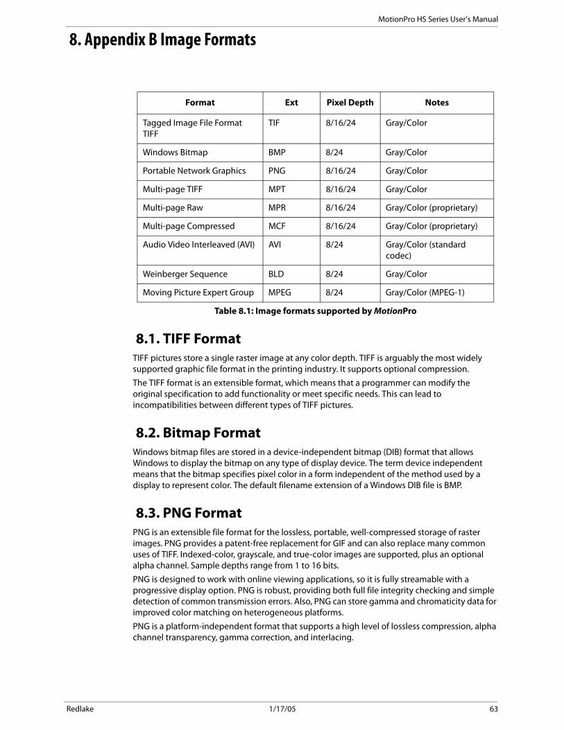
8. Appendix B Image Formats
8.1. TIFF FormatTIFF pictures store a single raster image at any color depth. TIFF is arguably the most widely supported graphic file format in the printing industry. It supports optional compression.
The TIFF format is an extensible format, which means that a programmer can modify the original specification to add functionality or meet specific needs. This can lead to incompatibilities between different types of TIFF pictures.
8.2. Bitmap FormatWindows bitmap files are stored in a device-independent bitmap (DIB) format that allows Windows to display the bitmap on any type of display device. The term device independent means that the bitmap specifies pixel color in a form independent of the method used by a display to represent color. The default filename extension of a Windows DIB file is BMP.
8.3. PNG FormatPNG is an extensible file format for the lossless, portable, well-compressed storage of raster images. PNG provides a patent-free replacement for GIF and can also replace many common uses of TIFF. Indexed-color, grayscale, and true-color images are supported, plus an optional alpha channel. Sample depths range from 1 to 16 bits.
PNG is designed to work with online viewing applications, so it is fully streamable with a progressive display option. PNG is robust, providing both full file integrity checking and simple detection of common transmission errors. Also, PNG can store gamma and chromaticity data for improved color matching on heterogeneous platforms.
PNG is a platform-independent format that supports a high level of lossless compression, alpha channel transparency, gamma correction, and interlacing.
Format Ext Pixel Depth Notes
Tagged Image File Format TIFF
TIF 8/16/24 Gray/Color
Windows Bitmap BMP 8/24 Gray/Color
Portable Network Graphics PNG 8/16/24 Gray/Color
Multi-page TIFF MPT 8/16/24 Gray/Color
Multi-page Raw MPR 8/16/24 Gray/Color (proprietary)
Multi-page Compressed MCF 8/16/24 Gray/Color (proprietary)
Audio Video Interleaved (AVI) AVI 8/24 Gray/Color (standard codec)
Weinberger Sequence BLD 8/24 Gray/Color
Moving Picture Expert Group MPEG 8/24 Gray/Color (MPEG-1)
Table 8.1: Image formats supported by MotionPro
Redlake 1/17/05 63

MotionPro HS Series User’s Manual
8.4. AVI FormatThe Microsoft AVI file format is a Resource Interchange File Format (RIFF) file specification used with applications that capture, edit, and playback audio-video sequences.
In general, AVI files contain multiple streams of different types of data. Most AVI sequences use both audio and video streams. A simple variation for an AVI sequence uses video data and does not require an audio stream.
8.5. BLD FormatThe BLD format corresponds to the file format RAW. Each BLD file needs a corresponding descriptor file in DSC format. In a BLD file, all single frames of an image sequence are stored successively, uncompressed in the block format. The data is in binary raw data format (e.g. for grayscale pictures 1 Byte per Pixel). The descriptor file (DSC) belonging to the BLD file is a line-orientated ASCII file, in which values such as resolution, frames or dates are stored. The DSC file can be created with any text editor.
8.6. MPEG FormatMPEG, or Moving Picture Experts Group, is a family of standards used for coding audio-visual data in a digital compressed format. MPEG is a generic means of compactly representing digital video and audio signals for consumer distribution. The basic idea is to transform a stream of discrete samples into a bitstream of tokens which takes less space, but is just as appealing to the eye. The graphic library implements the MPEG-1 format, the standard on which such products as video CD and MP3 are based. The compression and decompression technique implemented in MPEG is lossy.
8.7. Multi-page Raw Format (MRF)Multi-page Raw Format (MRF) is an uncompressed proprietary file format. Multiple raster images are stored in a single file.
Each MRF file contains a file header, an image header and an array of bytes that defines the image data bits. The image raster data is not compressed and stored in the file in its original format. Both 8-bit and 16-bit data formats are supported.
8.7.1. MRF File HeaderA MRF file begins with a file header structure containing the raw file signature.
typedef struct _RCFILE_HEADER
{
char szSign[8]; // raw file signature
unsigned long nReserved; // reserved
}}RCFILE_HEADER, *PRCFILE_HEADER;
8.7.2. MembersszSign[8]: an 8 char buffer which contains the signature "IDT-MRF". It indicates that the remainder of the file contains a Multiple Raw File.
nReserved: this field is reserved for future use.
8.7.3. Image HeaderThe file header is followed by the image header which contains general information about the data stream.
typedef struct _RCIMG_HEADER
{
unsigned long nSize; // size of this header
Redlake 1/17/05 64

MotionPro HS Series User’s Manual
unsigned long nPages; // number of pages/frames
unsigned long nWidth; // image width
unsigned long nHeight; // image height
unsigned long nBPP; // bits per pixel
unsigned long userData[64]; // user data array
} RCIMG_HEADER, *PRCIMG_HEADER;
8.7.4. MembersnSize: size of the structure in bytes. It should be 84.
nPages: number of images contained in the file
nWidth: width of each image in pixels.
nHeight: height of each image in pixels.
nBPP: number of bits per pixels (8, 10 or12)
userData: an array of 64 unsigned long to store user-defined information.
8.7.5. Data arraysThe image header is followed by the images data. Images are stored contiguously in uncompressed format.
8.8. Multi-page Compressed Format (MCF)Multi-page Compressed Format (MCF) is a compressed proprietary file format. Multiple raster images are stored in a single file. The format is described below.
Each MCF file contains a file header, an image header and an array of bytes that defines the image data bits. The image raster data is compressed and stored in the file. Both 8-bit and 16-bit data formats are supported.
8.8.1. File headerA MRF file begins with a file header structure containing the raw file signature.
typedef struct _RCFILE_HEADER
{
char szSign[8]; // IDT raw file signature
unsigned long nReserved; // reserved
} RCFILE_HEADER, *PRCFILE_HEADER;
8.8.2. MembersszSign[8]: a 8 char buffer which contains the signature IDT-MCF. It indicates that the remainder of the file contains a Multiple Compressed File.
nReserved: this field is reserved for future use.
Redlake 1/17/05 65

MotionPro HS Series User’s Manual
8.8.3. Image headerThe file header is followed by the image header which contains general information about the data stream.
typedef struct _RCIMG_HEADER
{
unsigned long nSize; // size of this header
unsigned long nPages; // number of pages/frames
unsigned long nWidth; // image width
unsigned long nHeight; // image height
unsigned long nBPP; // bits per pixel
unsigned long userData[64]; // user data array
} RCIMG_HEADER, *PRCIMG_HEADER;
8.8.4. MembersnSize: size of the structure in bytes. It should be 84.
nPages: number of images contained in the file.
nWidth: width of each image in pixels.
nHeight: height of each image in pixels.
nBPP: number of bits per pixels (8, 10 or12).
userData: an array of 64 unsigned long to store user-defined information.
8.8.5. Data arraysThe image header is followed by the image data. Images are stored contiguously in compressed format. The first four bytes contains the size of the compressed buffer, followed by image data.
Data compression is done using ZLIB library version 1.1.4, which is free and available for download at the URL http://www.zlib.org.
The compression algorithm used by ZLIB is a variation of LZ77 (Lempel-Ziv 1977). It finds duplicated strings in the input data. The second occurrence of a string is replaced by a pointer to the previous string, in the form of a pair (distance, length). Distances are limited to 32K bytes, and lengths are limited to 258 bytes. When a string does not occur anywhere in the previous 32K bytes, it is emitted as a sequence of literal bytes.
0-bit images acquired from the camera may be saved in different 16 bit formats. These formats include TIF, PNG, MPT, MRF and MCF. Since 16 bit grayscale format is not a standard, not all of the applications for image processing may correctly display the saved images.
Redlake 1/17/05 66

MotionPro HS Series User’s Manual
9. Appendix C Spatial filtering
Spatial filters alter pixel values with respect to variations in light intensity in their neighborhood. The neighborhood of a pixel is defined by the size of a matrix, or mask, centered in the pixel itself. These filters can be sensitive to the presence or the absence of light intensity variations. Spatial filters can serve a variety of purposes, such as detecting edges along a specific direction, contouring patterns, reducing noise, detail outlining and smoothing.
Spatial filters fall in two categories:
High-pass filters: emphasize significant variations of the light intensity usually found at the boundary of object. They are also called sharpening filters.
Low-pass filters: attenuate variations of the light intensity. They have the tendency to smooth images by eliminating details and blurring edges. They are also called smoothing filters.
In the case of a 3x3 matrix, the value of the central pixel derives from the values of its eight surrounding neighbors. A 5x5 matrix specifies 24 neighbors; a 7x7 matrix specifies 48 neighbors and so forth.
If P(i,j) specifies the intensity of the pixel P with the coordinates (i,j), the pixels surrounding P(i,j) can be indexed as follows (in the case of a 3x3 matrix):
A linear filter assigns to P(i,j) a value which is a linear combination of its surrounding values. For example:
P(i,j) = P(i-1,j-1) + P(i,j-1) + P(i+1, j-1) - P(i-1,j+1) - P(i,j+1) - P(i+1,j+1)
A nonlinear filter assigns to P(i,j) a value that is not a linear combination of the surrounding values. For example:
P(i,j) = max( P(i-1,j-1), P(i+1, j-1), P(i-1,j+1), P(i+1,j+1) )
9.1. Linear filters (Convolution filters)A convolution is a mathematical function that replaces each pixel by a weighted sum of its neighbors. The matrix defining the neighborhood of the pixel also specifies the weight assigned to each neighbor. This matrix is called the convolution kernel.
For each pixel P(i,j) in an image, the convolution kernel is centered on P(i,j). Each pixel masked by the kernel is multiplied by the coefficient placed on top of it. P(i,j) becomes the sum of these products.
In the case of a 3x3 neighborhood, the coefficients of the kernel matrix can be indexed as follows:
P (i-1,j-1) P(i,j-1) P(i+1,J-1)
P(i-1,j) P(i,j) P(i+1,j)
P(i-1,j+1) P(i,j+1) P(i+1j+1)
K(i-1,j-1) K(i,j-1) K(i+1,j-1)
K(i-1j) K(i,j) K(i+1,j)
K(i-1,j+1) K(i,j+1) K(i+j+1)
Redlake 1/17/05 67

MotionPro HS Series User’s Manual
The greater the absolute value of a coefficient K(a,b), the more the pixel P(a,b) contributes to the new value of P(i,j). If a coefficient K(a,b) is 0, the neighbor P(a,b) does not contribute to the new value of P(i,j)
then
P(i,j) = P(i,j-1) + P(i-1,j) + P(i+1, j) + P(i,j+1)
If the kernel contains both negative and positive coefficients, the transfer function is equivalent to a weighted differentiation and produces a sharpening or high-pass filter (similar to Laplacian, Prewitt and Sobel filters).
If all coefficients in the kernel are positive, the transfer function is equivalent to a weighted summation and produces a smoothing or low-pass filter (like Average and Gaussian filters).
9.2. Linear sharpening filtersTypical smoothing filters are: Gradient filters
A gradient filter highlights the variation of light intensity along a specific direction, which has the effect of outlining edges and revealing texture.
A gradient convolution filter is a first-order derivative. Its kernel uses the following matrix:
Where a, b, c and d are integer coefficients and x=0 or x=1.
This kernel has an axis of symmetry that runs between the positive and negative coefficients of the kernel and through the central element. This axis of symmetry gives the orientation of the edges to outline.
There are two sets of pre-defined gradient filters used in MotionPro Central.
Prewitt filters: have the following kernels. The notations N (north) NE(north-east) E (east) SE (south-east) S (south) SW (south-west) W (west) NW (north-west) indicate which edges of bright regions they outline.
Sobel filters: are very similar to the Prewitt filters except that they highlight light intensity variations along a particular axis that is assigned a stronger weight.
0 1 0
1 0 0
0 1 0
a -b c
b x -d
c d -a
Redlake 1/17/05 68

MotionPro HS Series User’s Manual
9.2.1. Laplacian FilterA Laplacian filter highlights the variation of the light intensity surrounding a pixel. The filter extracts the contour of objects and outlines details. Unlike the gradient filter, it is omni-directional.
The Laplacian filter is a second-order derivative. Its kernel uses the following matrix:
where a, b, c and d are integers.
The Laplacian filter has two different effects, depending on whether the central coefficient X is equal or greater than the sum of the absolute values of the outer coefficients.
If X is equal to that sum, the filter extracts the pixels where significant variations of light intensity are found. The presence of sharp edges, boundaries between objects, modification in the texture of a background noise, and other affects can cause these variations. The transformed image contains white contours on a black background.
If x is greater than that sum, the filter detects the same variations as mentioned above, but superimposes them over the source image. The transformed image looks like the source image, with all significant variations of the light intensity highlighted.
9.3. Linear Smoothing filtersA smoothing filter attenuates the variations of light intensity in the neighborhood of a pixel. It smooths the overall shape of objects, blurs edges, and removes details.
It is an averaging filters and its kernel uses the following matrix:
where a, b, c and d are positive integers, and x=0 or x=1.
Because all the coefficients are positive, each central pixel becomes a weighted average of its neighbors. The stronger the weight of a neighbor is the more influence it has on the new value of the central pixel.
A list of average smoothing kernels is shown below
Gaussian
A Gaussian filter attenuates the variations of light intensity in the neighborhood of a pixel. It smooths the overall shape of objects and attenuates details. It is similar to a smoothing filter, but its blurring effect is more subdued.
Its kernel uses the following matrix.
a d c
b x b
c d A
a d c
b x b
c d a
a d c
b x b
c d a
Redlake 1/17/05 69

MotionPro HS Series User’s Manual
where a, b, c and d are positive integers, and x=0 or x=1.
Because all the coefficients are positive, each central pixel becomes a weighted average of its neighbors. The stronger the weight of a neighbor is, the more influence it has on the new value of the central pixel.
Unlike a smoothing kernel, the central coefficient of a Gaussian filter is greater than 1. Therefore, the original value of a pixel is multiplied by a value greater than the weight of any of its neighbors. As a result, a greater central coefficient corresponds to a more subtle smoothing effect. A larger kernel size corresponds to a stronger smoothing effect.
9.4. Nonlinear filtersA nonlinear filter replaces each pixel with a nonlinear function of its surrounding pixels. Like the convolution filters, the nonlinear filters operate by checking its neighborhood.
Median filter: is a nonlinear low pass filter that assigns to each pixel the median value of its neighborhood, effectively reducing isolated pixels and reducing details. However, the median filter does not blur the contour of objects.
Maximum Filter: is a nonlinear filter that assigns each pixel the maximum value of pixels in its neighborhood. This increases the contrast of the image.
Dilation: of an image is a particular case of max filter. The output pixel is set to the maximum of the corresponding input pixel and its 8 neighbors. The effect of dilation is to fill up holes and to thicken boundaries of objects on a dark background (that is, objects whose pixel values are greater than those of the background).
Minimum Filter: is a nonlinear filter that assigns each pixel the minimum value of pixels in its neighborhood. This decreases the contrast of the image.
Erosion: of an image is a particular case of minimum filter. The output pixel is set to the minimum of the corresponding input pixel and its eight neighbors. The effect of erosion is to remove spurious pixels (such as noise) and to thin boundaries of objects on a dark background (that is, objects whose pixel values are greater than those of the background).
Opening: an image is a sequence of erosions followed by dilations. Opening eliminates small and thin objects, breaking objects at thin points, and generally smoothing the boundaries of larger objects without significantly changing their area.
Closing: an image is a sequence of dilations followed by erosions. Closing fills small and thin holes in objects, connecting nearby objects, and generally smoothing the boundaries of objects without significantly changing their area.
9.5. Adding noise to imagesA random noise signal may be generated and added to an image. Two different noise signals may be generated.
Uniform noise: a noise signal with uniform distribution over a range [low, high].
Gaussian noise: a noise signal with Gaussian distribution that has a specified mean value and a specified standard deviation.
Redlake 1/17/05 70

MotionPro HS Series User’s Manual
10. Appendix D Look Up Table (LUT) Transformations
The Look Up Table (LUT) transformations are basic image-processing functions for improving the contrast and the brightness of an image by modifying the dynamic intensity of region with poor contrast. LUT transformations can highlight details in areas containing significant information, at the expense of other areas.
A LUT transformation converts input gray-level values (8 or 16 bit) into other gray-level values. The transfer function has an intended effect on the brightness and contrast of the image. Each input value is transformed into a new value by a transfer function:
Output value = F (input value)
Where F is a linear or nonlinear, continuous or discontinuous transfer function defined over the interval [0, max]. In an 8-bit image, a LUT contains 256 elements. Each element of the array rep-resents an input value. Its content indicates the output value.
Five different LUT types are available in MotionCentral Pro: linear, equalize, logarithmic, expo-nential and gate. The table below shows the transfer function for each LUT type.
ResolutionTransfer Function
Description
Linear A linear transfer function ( y = ax + b) affects both the brightness and contrast of the image. The parameter b (offset) increases or decreases the image brightness, while the parameter s (gain) influences the image contrast.
Equalize The equalize function alters the gray-level value of pixels so they become distributed evenly in the defined grayscale range (0 to 155 for an 8 bit image) The function associates an equal amount of pixels per constant gray-level interval and takes full advantage of the available shades of gray.
LogarithmicThe logarithmic function expands low gray-level ranges while compressing high level ranges. These transformations increase the overall brightness of an image and increase the contrast in dark areas at the expense of the contrast in bright areas.
Table 10.1: Look Up Table Description
Redlake 1/17/05 71

MotionPro HS Series User’s Manual
Exponential The exponential function expands high gray-level ranges while compressing low level ranges. These transformations decrease the overall brightness of an image and increase the contrast in bright areas at the expense of the contrast in dark areas.
GateThe gate function sets all the gray-level values to zero that are below a certain value and above another one. The other gray-level values remain unaltered.
ResolutionTransfer Function
Description
Table 10.1: Look Up Table Description
Redlake 1/17/05 72

MotionPro HS Series User’s Manual
11. Appendix E Color Filter Arrays (CFA)
The MotionPro HS series Color camera uses a single image sensor. Color imaging with a single sensor requires the use of a Color Filter Array (CFA) which covers the sensor array. Each pixel in the detector samples the intensity of just one of the three color components, i.e. red, green or blue. The recovery of full-color images from a CFA-based sensor requires a method of calculating values of the other color separations at each pixel. These methods are commonly referred as color interpolation or color demosaicing algorithms.
In a single-sensor camera, varying intensities of light are measured at a rectangular grid of image sensors. To construct a color image, a CFA must be placed between the lens and the sensors. A CFA typically has one color filter element for each sensor. Obviously, the color interpolation algorithms depend on the CFA configuration. The CFA used in MotionPro HS cameras is the Bayer pattern.
A Bayer pattern consists of pixels on the sensor tinted green, red or blue and set in a mosaic pattern. In the figure below: moving from left to right and then down, there is a GR-BG pattern. This is a Bayer pattern, that is placed all over the sensor to form the Bayer Mosaic Pattern. The result is half of the pixels are tinted with a green sensitive element, a quarter tinted with a red sensitive element, and a quarter tinted with a blue sensitive element.
The MotionPro driver performs six different interpolation algorithms (demosaicing):
"Bilinear: for each missing pixel, a weighted value of the surrounding four pixels is computed. It's the simplest method and is non-adaptive. The indiscriminate averaging of neighboring pixel causes a blur effect ("Zipper").
"Gradient A: the interpolation is done using chrominance gradients in two steps. First the luminance channel is interpolated (green). Then the color differences (red minus green and blue minus green) are interpolated.
"Gradient B: the interpolation is done using luminance gradients in a more adaptive way than algorithm B.
"Gradient C: the interpolation is done using a threshold based variable number of gradients.
"Hue Transition A: the algorithm is based on the assumption that the hue of the image cannot change abruptly and in an unnatural manner. The term hue refers to the relation between luminance (green) and chrominance (red, blue).
"Hue Transition B: based on the same principles of "A" method, but more precise
Figure 11.1: Bayer Pattern
Redlake 1/17/05 73

MotionPro HS Series User’s Manual
"Pixel Grouping: the algorithm is based on the observation that natural scene images are usually composed of numerous groups of pixels, and have approximately the same brightness and color.
Redlake 1/17/05 74