users‘ manual - spot onspot-on.net/images/get-geo electronic theodolite.pdf · 3 1 important!...
TRANSCRIPT

Users‘ manual
Electronic TheodoliteFET 420K / FET 405K

2
CONTENTS
1) Important 3 2) Usage 3 3) Features(1) 4 4) Features(2) 4 5) Displayindication 5 6) Operatingpanel 5 7) Preparationformeasurement 6 8) Poweron 7 9) Batteryindication 810) Batteryreplacement 811) Anglemeasurement 912) HorizontalangleOSet 913) Measuringhorizontalandverticalangle(HR,VorHL,V) 1014) Modeconversionofhorizontalrightward(HR)andleftward(HL) 10 turningincrement15) Horizontalanglelocked-unlocked 1116) Measurementofzenithdistance,verticalangleandheightangle 1217) Angularrepeatedmesurement 1318) Functionsetting 1419) Settingmethods 1420) Factorysettings 1521) Errordisplay 1522) Mountanddismountofthebaseplate 1623) Checkandadjusting 1624) Technicalspecification 2225) Careandcleaning 2226) Intendeduseofinstrument 2227) Safetyinstructions 2328) Specificreasonsforerroneousmeasuringresults 2329) Electromagneticacceptability(EMC) 2330) CE-conformity 2331) Guarantee 2432) Exceptionsfromresponsibility 24

3
1 IMPORTANT! READTHISBEFOREUSINGYOURINSTRUMENT
Makeafullcheckfortheinstrumentbeforeusingit.Besurethattheinstrument’sfunctions, power,originalsettingsandrevisedparametersmeetyourrequirementsbeforeyouoperateit.
Toavoiddirectsunlighttotheinstrument’slens,neverleavetheinstrumentexposedtoex- tremeheatlongerthannecessary,oritcouldaffecttheinstrument’saccuracy.
Whenmountingordismountingtheinstrumenttoorfromthetripod,holdtheinstrumentbyone hand,turnthecentralscrewonthetripodbytheotherhandtopreventtheinstrumentfrom falling.Iftheinstrumentmustbecarriedonthetripod,holdtheinstrumentasverticallyas possible.Nevercarrytheinstrumenthorizontallyoveryourshoulder.Anylongdistancetransport shouldbedonewiththeinstrumentinthecarryingcase.
Puttheinstrumentinthecarryingcasetoavoidextrusion,crashandshockduringthetranspor- tation.Shockproofcushionshouldbenecessarilyputinsidethecarryingcaseduringthelong distancetransportation.
Cleanthedirtonthesurfaceoftheorganicglassandplasticbyflossorbrushafterusingthe instrument.Drytheinstrumentintimeafteruseintherain.
Donotuseharshchemicalstocleanthesurfaceoftheorganicglassandplasticcomponents. Awaterdampenedragisallthatisnecessary.
Useabsorbentcottonorlensestissuetocleantheexposedopticalparts.Handkerchief,clothes orotherthingslikethatareforbiddenforcleaning.
Theinstrumentshouldbestoredinanareaoflowhumidityandgoodventilation,wherethe temperaturewillnotexceed110ºF(45ºC).Itshouldbenecessarytoreplacethedesiccant regularlyinthecarryingcase.
Alwaysremovethebatteriesbeforestoringtheinstrument.Pleasecontactourcompanyiftheinstrument’sfunctionsappearabnormal.Non-professional
repairersareforbiddentodisassembletheinstrument.
•
•
•
•
•
•
•
•
••
2 USAGE
ElectronicDigitalTheodoliteFET420/405Kserieshasadoptedincrement-modedigitssystem foranglemeasurement. Theresolvingpowerofhorizontalandverticalanglescanreach10”. Theprecisionofanglemeasurementcanreach20”. ElectronicDigitalTheodoliteFET420/405Kcanbewidelyusedin3-4classnationaltriangle controlmeasurement,preciseleadmeasurement,engineeringmeasurementformine,railway waterconservancyandsoon,landformmeasurement,andalsocouldbeusedintheassembly ofthelargemachineryfacilities. Thedisplaysareilluminatedsoastomakeitconvenienttooperateinthedarkerenvironment.

4
4 FEATURES(2)
1) Focusingknob 2) Opticalplummet 3) Communicationplug 4) Footscrew 5) Batterycompartment 6) Telescopeeyepiece 7) Verticalclampknob 8) Verticaltangentscrew 9) Clampoftribrach
3 FEATURES(1)
1) Opticalsight 2) Objectivelens 3) Horizontalclampknob 4) Horizontaltangentscrew 5) Display 6) Operatingkeys 7) Tripodbaseplate 8) Carryinghandle 9) Handlescrew10) Instrumentcentermark11) Platevial12) Circularvial

5
6 OPERATINGPANEL
Button Function FUNC Optionalfunctionkeys Lightingswitchfordisplaywindow REP Repeatedanglemeasurement HOLD Holdhorizontalangle V/% Verticalangledisplay Verticalangle/percentdisplay R/L Optionofleft/righthorizontalangle 0SET 0SETforhorizontalangle Powerswitch Movecursorleftward Movecursorrightward Alterthenumbercursorindicated
ΔΔ
Δ
5 DISPLAYINDICATION
1) Ht Generalvalueofrepeatedmeasurements 2 V Verticalangle 3) Numberofrepeatedmeasurements 4) AVG Averageofrepeatedmeasurements 5) HR Righthorizontalangle 6) HL Lefthorizontalangle 7) TILT Inclinecompensatorfunction 8) F Optionalfunctionkeys 9) G AngleunitGON10) % Verticalslope%11) REP Stateofrepeatedmeasurement12) BAT Batterystateindication
Ifdisplayshows“b”afteractivatinginclinecompensation function,whichmeansexceededcompensationrange,the instrumentshouldbelevelled.

6
7 PREPARATIONFORMEASUREMENT
Levelandcentertheinstrumentpreciselytoensureitsbestperformance.
a Mountthetripod Firstlyplacethetripodlegstoasuitablepositionandtightenthelockingdevice. b Mounttheinstrument Attachtheinstrumenttothetripodcarefully,andthenmovetheinstrumentbyloosening centerscrew.Lockslightlythecenterscrewonthetripodwhentheplummetiscentered abovethemark. c Roughlyleveltheinstrumentwiththecircularvial 1Usefootscrew1,2tomovetheairbubbleinthecircularvialsoitiscenteredlefttoright. 2Usefootscrew3tomovetheairbubbletothecenterofthevial.
d Finetuneleveltheinstrumentwiththeplatelevel 1Loosenhorizontalclampknob.Turntheinstrumenttoplacetheplatevialparallelwith thefootscrew1,2.Centerthebubbleusingthesetwofootscrews.Attention:Turnthetwo footscrewsreverselywhenyouadjustthem. 2Turntheinstrument90°andcenterthebubbleusinglevelscrew3. 3Repeatstep1,2everytimetheinstrumentisturned90°tocenterallthebubblesinthese positions.
4ReturntotheoriginalpositioninstepA.Rotatetheinstrument180°.Theplatevialis mountedcorrectlyandtheinstrumentislevelednicelyifthebubbleiscenterednomatter theinstrumentisrotatedinanydirection.Atthepositionofstep1,rotatethecollimating section180°.Theplatelevelismountedcorrectlyandtheinstrumentislevellednicelyif thebubbleiscenterednomatterwhatdirectionthecollimatingsectionisrotated.
Pleasepayattentiontotherelationsbetweentheturningdirectionofthelevelscrewsand themovingdirectionofthebubble.
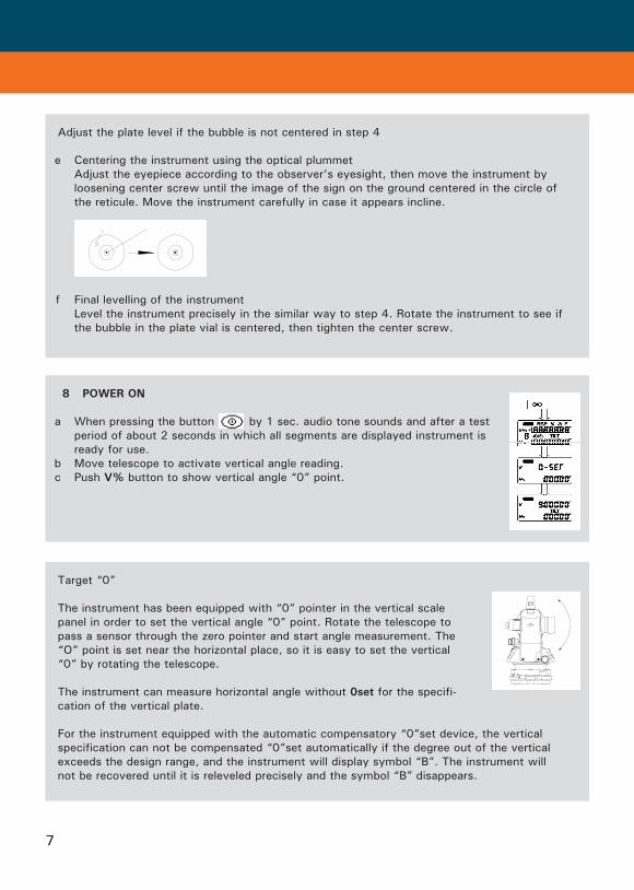
Adjusttheplatelevelifthebubbleisnotcenteredinstep4
e Centeringtheinstrumentusingtheopticalplummet Adjusttheeyepieceaccordingtotheobserver’seyesight,thenmovetheinstrumentby looseningcenterscrewuntiltheimageofthesignonthegroundcenteredinthecircleof thereticule.Movetheinstrumentcarefullyincaseitappearsincline.
f Finallevellingoftheinstrument Leveltheinstrumentpreciselyinthesimilarwaytostep4.Rotatetheinstrumenttoseeif thebubbleintheplatevialiscentered,thentightenthecenterscrew.
8 POWERON
a Whenpressingthebuttonby1sec.audiotonesoundsandafteratest periodofabout2secondsinwhichallsegmentsaredisplayedinstrumentis readyforuse. b Movetelescopetoactivateverticalanglereading. c PushV%buttontoshowverticalangle“0”point.
7
Target“0”
Theinstrumenthasbeenequippedwith“0”pointerintheverticalscale panelinordertosettheverticalangle“0”point.Rotatethetelescopeto passasensorthroughthezeropointerandstartanglemeasurement.The “O”pointissetnearthehorizontalplace,soitiseasytosetthevertical “0”byrotatingthetelescope.
Theinstrumentcanmeasurehorizontalanglewithout0setforthespecifi- cationoftheverticalplate.
Fortheinstrumentequippedwiththeautomaticcompensatory“0”setdevice,thevertical specificationcannotbecompensated“0”setautomaticallyifthedegreeoutofthevertical exceedsthedesignrange,andtheinstrumentwilldisplaysymbol“B”.Theinstrumentwill notberecovereduntilitisreleveledpreciselyandthesymbol“B”disappears.
7

8
10 BATTERYREPLACEMENT
a Removingthebattery Pushdownthepressbuttonandremovethebatterycompartment. bBatteryreplacement Pushdownthehooktopullcoverboardawayfromthebatterycompartment. Replacetheoldbatteriesbynewones.Takecareofcorrectpolarity. Snapthebatterycoverbackintoplace. cMountingbatterycompartment Sliptheprojectiononthebottomofthebatterycompartmentintotheslot.Pushthepress buttonontopofthebatterycompartmentuntilitclicksintoplace.
9 BATTERYINDICATION
Thebatterysymbolonthedisplayshowsthecurrentbatterystate.
Fullpower Effective Effective Lowpowerbuteffective,replacethebattery. Instrumentwillshutoffautomaticallyshortly.Replacebatteriesimmediately.
Batteryoperatingtimewillvarydependingontype,brandandqualityofthebattery.We suggestalwaystosecurefora2ndstandbybatteryset. Foranyquestionsaboutreplacingbatteries,seechapter“batteryreplacement”.

11 ANGLEMEASUREMENT
Verticalplateleft/rightobservation “Plateleft”meanstheverticalplateisontheleftsidebythetelescopewhentheobserverfaces theeyepiece.“Plateright”meanstheoppositetothe“plateleft”.Takingtheaveragereadingof the“plateleft”and“plateright”astheobservationvaluecaneffectivelyremovethecorrespon- dingeffectontheobserverfromthesystemerrorsintheinstrument.Therefore,turntheteles- cope180°forthe“plateright”observationaftertheaccomplishofthe“plateleft”duringthe observationofthehorizontalandverticalangle.
Targetaim Pointthetelescopeatthebrightnessandfocustheeyepieceuntilthecrosshaircanbeseen clearly.(Turnthefocusingknobinthedirectionfacingtheobserver,thenfocusinreverse direction.) Aimatthetargetcoarselyusingthecoarseaimingdevice.Thedefinitespacecanbekept betweenthedeviceandtheobserverwhenaimingcoarsely. Focusthetargetbyturningthefocusingknobonthetelescope. Attention: Thevisualerrorsofthetargetandreticulecrosshairwillbecreatedinthehorizontalandvertical directionifthetelescopeortheeyepiecearenotfocusedprecisely,whichcanresultinthe measuringerrors.Focusforthetelescopeandeyepieceshouldbenecessarytoremovethe visualerrors.
9
12 HORIZONTALANGLEOSET(OSET)
OPERATINGPROCESS DISPLAY
AimattargetAusingcrosshairofthetelescope.
Press0SETkeyoncetosetreadingofhorizontalangle0°00’00”:
0SETkeyisonlyeffectivetothehorizontalangle.
Horizontalanglecanbeset0atanytimeexcepttheholding state(HOLDkey).

10
13 MEASURINGHORIZONTALANDVERTICALANGLE(HR,VorHL,V)
Horizontalrightwardturningincrementandverticalanglemeasurement/HR,V)
OPERATINGPROCESS DISPLAY
AimattargetAusingcrosshairofthetelescope.
Press0SETkeyoncetosetreadingofhorizontalangle0°00’00”.
TurninstrumentclockwiseandaimatthesecondtargetBtogetits horizontalandverticalangle.
14 MODECONVERSIONOFHORIZONTALRIGHTWARD(HR)ANDLEFTWARD(HL) TURNINGINCREMENT
OPERATINGPROCESS DISPLAY
Aimattarget“A”usingcrosshairofthetelescope.
PressR/Lkey,transformhorizontalanglemodeHRinto themodeHL.
MeasuringbymodeHL.
R/Lkeyisofnoeffecttotheverticalangle. PressR/Lkeyagain,transformmodeHLintomodeHR.

11
15 HORIZONTALANGLELOCKED-UNLOCKED
Duringtheprocessoflevelobservation,pressHOLDkeyoncetokeepthemeasuringangle. Afterthehorizontalangleheld,thevalueofthehorizontalangleonthedisplaywindowblinks. Thereisnochangetothehorizontalangleeveniftheinstrumentisrotated.Whenthedirection aimedcorrectly,pressHOLDkeyonceagaintounlocktheholdingstate.Thedirectionofthe horizontalangletheinstrumentcurrentlyaimedisjusttheanglelockedbefore.
OERATINGPROCESS DISPLAY
Turnthetangentknobandplacetherequiredhorizontal angle.
PressHOLDkeyonce,holdandflickerthevalueofthe horizontalangle.
Aimatthetarget.
PressHOLDkey,noblinkandholdtothevalueofthe horizontalangle.
HOLDkeyisofnoeffecttotheverticalangle.

12
16 MEASUREMENTOFZENITHDISTANCE,VERTICALANGELANDHEIGHTANGLE
Theverticalangleshouldbeoriginallysetaccordingtotheneedsbeforetheoperation.
ZENITHDISTANCE Ifchoose0°fortheverticalangleasthezenithdirection,themeasuredverticalangleV isthezenithangle. ZENITHDISTANCEV=(L+360°-R)/2 SPECIFICATONERRORi=(L+R-360°)/2
VERTICALANGLE Ifchoose0°fortheverticalangleinleftdirection,themeasuredverticalangleVisthe verticalangle. VERTICALANGLEV=(L+180°-R)/2 SPECIFICATIONERRORi=(L+R-540°)/2
HEIGHTANGLE Ifchoose0°fortheverticalangleinbothleftandrightdirection,themeasuredvertical angleVistheheightangle. HEIGHTANGLEV=(L+R)/2 SPECIFICATIONERRORi=(L–R)/2 ATTENTION:IfSPECIFICATIONERROR|i|≥10“inspectandadjustaccordingtothe instructionmanual.
SLOPEPERCENTMODE(slopeanglemeasurement) Measuringinanglemode,theverticalanglecouldbetransformedintopercentofgrade. Thepercentofgradevalue=H/D*100%: Therangeofgradepercentisfromthehorizontaldirectionto±45°.
OPERATINGPROCESS DISPLAY
PressV%keytoswitchfromverticalangularmeasure- mentshownindegreestopercent.
PressV%keyonceagainbacktotheangularmeasure- mentshownindegrees.
Anyangleexceeding100%thepercentofgradewillbe shownas“-----”onthedisplay.
13
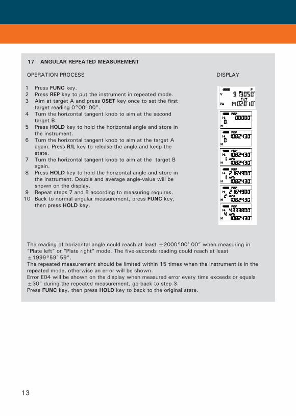
17 ANGULARREPEATEDMEASUREMENT
OPERATIONPROCESS DISPLAY
1 PressFUNCkey. 2 PressREPkeytoputtheinstrumentinrepeatedmode. 3 AimattargetAandpress0SETkeyoncetosetthefirst targetreading0°00’00”. 4 Turnthehorizontaltangentknobtoaimatthesecond targetB. 5 PressHOLDkeytoholdthehorizontalangleandstorein theinstrument. 6 TurnthehorizontaltangentknobtoaimatthetargetA again.PressR/Lkeytoreleasetheangleandkeepthe state. 7 TurnthehorizontaltangentknobtoaimatthetargetB again. 8 PressHOLDkeytoholdthehorizontalangleandstorein theinstrument.Doubleandaverageangle-valuewillbe shownonthedisplay. 9 Repeatsteps7and8accordingtomeasuringrequires.10 Backtonormalangularmeasurement,pressFUNCkey, thenpressHOLDkey.
Thereadingofhorizontalanglecouldreachatleast±2000°00’00”whenmeasuringin “Plateleft”or“Plateright”mode.Thefive-secondsreadingcouldreachatleast ±1999°59’59”. Therepeatedmeasurementshouldbelimitedwithin15timeswhentheinstrumentisinthe repeatedmode,otherwiseanerrorwillbeshown. ErrorE04willbeshownonthedisplaywhenmeasurederroreverytimeexceedsorequals ±30”duringtherepeatedmeasurement,gobacktostep3. PressFUNCkey,thenpressHOLDkeytobacktotheoriginalstate.
14
18 FUNCTIONSETTING
Theinstrumentsuppliesmulti-functionsforyouroptiontomeetdifferentrequiresof measuringconfiguration.
ITEM INSTRUCTION PARAMETERSETTING
1 Minimumrea- Changebetween10“ Setting0 Setting1 ding and20“ 10“ 20“
2 Quadrant Confirmevery90° Setting0 Setting1 signaltone bysignaltone off on
3 Unitofangle ChangebetweenDEG, Setting0/DEG Setting2/MIL measurement (degree),GON,MIL Setting1/GON Setting3/DEG
4 Autoshut-off Setintervalforauto- Setting0/Off Setting2/20min. maticshut-off Setting1/10min. Setting3/30min.
5 Measuring Set„0“pointofvertical SettingO Verticalangle modefor angle (0inhorizontal) verticalangle Setting1 Zenithangle (0inzenith) Setting2 Heightangle+/- (0inhoirzontal)
6 Automatic Setincline Setting0 Setting1 compensation correctionfunction Off On
7 Datatrans- Setdatatransmission Setting0 Setting1 mission function Off On
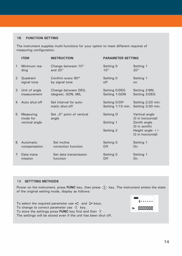
19 SETTTINGMETHODS
Powerontheinstrument,pressFUNCkey,thenpress key.Theinstrumententersthestate oftheoriginalsettingmode,displayasfollows:
Toselecttherequiredparameteruseandkeys. Tochangetocorrectparameterusekey. TostorethesettingspressFUNCkeyfirstandthen. Thesettingswillbestoredeveniftheunithasbeenshutoff.
Δ
Δ

15
21 ERRORDISPLAY
DISPLAY ERRORCONTENTANDDISPOSAL
B Verticalcompensatoroutofcompensatingrange. Leveltheinstrumentagain.
E00 Collimaterotatingtoofast.Press0SETkeytoset0. If“E00”isshownagaininstrumentneedstoberepaired.
E01 Telescopeturningtoofast,pressV/%keytoset0fortheverticalplate specification.
E02 Interiorerrorofthehorizontalanglemeasuringsystem.Poweronthein- strumentagain.Iferrorisshownagaininstrumentneedstoberepaired.
E03 Interiorerroroftheverticalanglemeasuringsystem. Iferrorisshownagaininstrumentneedstoberepaired.
E04 Differencebetweeneveryvalueexceeds30“duringtheanglerepeated measurement,press0SETkeyandmeasurerepeatedly.
E05 Numberofanglerepeatedmeasurementexceed15,presskeyandmeasure repeatedly.
E06 Errorsduringtheprocessoftheverticalangle0setoradjusting0setwhen theclampangletothehorizonexceeds45°.Needadjustingrepeatedly.
Attention: Fullycheckeverypartoftheinstrumentandseewhethertheoperationcoincideswiththe proceduresaftertheerrorappears.Iftheerrorcodeisstillshownaftermanychecksplease sendtheinstrumentforrepair.
20 FACTORYSETTINGS
Minimumreading 10“ Quadrantsignaltone off Unitofanglemeasurement 360° Automaticshut-off off Verticalanglemeasuring-mode zenithangle Automaticcompensation off Datatransmission off

16
22 MOUNTANDDISMOUNTOFTHEBASEPLATE
Looseningortighteningturninghandlecaneasilymountordismounttheinstrumenttoorfrom thebaseplate.
Dismount Turnthefixedpullhandle180°counterclockwise.Holdthebaseplatebyonehand,bringup theinstrumentusingthecarryinghandlebytheotherhand. Mount Bringuptheinstrumentbyhandandaimtheorientationblockattheorientationslot.Mountthe instrumentonthebaseplatecarefully.Tightenthefixedpullhandleonthebaseplate.
23 CHECKANDADJUSMENT
Adjustmentinstruction
Adjusttheeyepieceandfocusitpreciselytoavoidthevisualerrorsbeforetheobservation throughtelescope. Adjustmentshouldbecarriedoutonebyoneaccordingtothefollowingstepsbecauseeach step’sadjustmentisbasedonitsformerone’sresult.Disorderthestepswilldefaulttheadjust- ment. Tightenthescrewaftertheadjustment!Thestrengthappliedshouldbesuitablebecause overtightenwilldamagethethread. Aftertheadjustmentrepeattheinspectiontomakesurethattheadjustmenthasbeenwell done.
Inspectandadjusttheplatevial
Inspection Maketheplatevialparallelwithtwofootscrewsamongthethreeones. Centeritsbubblebyadjustingthetwofootscrews. Turntheinstrument180ºandobservethebubble.Adjustmentisneeded ifthebubbleisnotcentered. Adjustment Calibratetheplatevialbyusingtheadjustingpintoadjustitsscrewto makethebubblemovecenter-orientedhalfwayoftheoffset. Theotherhalfwaywillbeoffsetbyperformingtheadjustmentofthe twolevellingscrews,whichareparallelwiththelongvial. Turntheinstrument180°andcheckifthebubbleiscentered.Ifnot, repeatthestepsmentionedabovetillthebubbleiscentered. Turntheinstrument90°andcenterthebubblebyadjustingthethird levellingscrew.Repeatthecheckingandadjustmentstepsaboveuntil thebubblestayscenterednomatterinwhichdirection.
Offset 1/2

17
Inspectandadjustthecircularvial
Inspection Ifthecircularvialiscenteredcorrectlyafterlevellingtheinstrumentaccordingtothelongvial, thennofurtheradjustmentisnecessary.Ifnot,pleaseproceedwiththefollowingadjustment. Adjustment Therearethreeadjustingscrewsonthebottomofthecircularvial.Whenadjusting,loosenthe screwoppositetothebubble’smovingdirection(oneortwo),thentightentherestscrews alongthebubble’smovingdirectiontocenterthebubble.Thetighteningstrengthofthese threescrewsshouldbecoincided.
Adjusting screw
The bottom part Circular vial
Thetelescopereticule Inspection Mounttheinstrumentonthetripodandlevelitcarefully. SettargetpointA50meterstotheinstrument,aimatpointAbythestadiahairs. TurnthetelescopeandobservepointAwhetheritmovesalongtheverticalhair. IfpointAmovesalongtheverticalhair,thatmeanstheverticalhairisperpendiculartothe horizontalaxis,thennofurtheradjustmentisnecessary. AdjustmentisnecessaryifpointAmovesdeviatedfromtheverticalhair
Adjustment Turncounterclockwiseandremovethereticlecoverbetweentheeyepieceandfocusingknob, Thiswillexposefourreticlefixingscrews. Loosenthesefourfixingscrewsequablybyscrewdriver.Turnthereticlebasearoundthevisual axistosetpointAontheverticalhair. Tightenthesefourfixingscrewsequablyandobservewhetheranydeviationappearswhen pointAmovesalongtheverticalhair.Ifnot,theadjustmentisover. Assemblebackthereticlecovertoitsoriginalposition.
A
A'
A
A'
Adjusting screw
Fixing screw

18
Perpendiculardegreeofthevisualaxistothehorizontalaxis
Inspection Settwoobvioustargetsashighastheinstrumentabout100metersapartwiththeinstrument intheircenterpoint. Leveltheinstrumentpreciselyandpoweriton. AimattargetAusingcrosshairofthetelescopeplate-leftward. Loosentheverticalbrakingknob.Rotatethetelescopearoundthehorizontalaxis180°toaim itattheoppositedirection. AimattargetBwiththesamedistancetotargetA Rotatethehorizontalbrakingknobtoturntheinstrument180°. AimatthetargetA,thenlocktheknob. Rotatetheverticalbrakingknobtoturntheinstrument180°.AimattargetC.TargetC shouldbesuperposedtotargetB.Ifnot,adjustmentisnecessary.
Adjustment Removethereticulecoverbetweentheeyepieceofthetelescope andthefocusingknob. SetuppointDbetweenpointBandC.ThedistanceofDCshould beaquarterofBC.Adjustthetwoadjustingscrewstomovethe reticuletohaveitscrossaimatpointD. RepeataboveinspectionandadjustmentstepsuntilBandCare superposed. Assemblebackthereticulecovertoitsoriginalposition.
Loosenonescrewiftheverticalhairofthecrosshairshouldbe moved,thentightentheotheroneinthesameturn.Loosenthescrew counterclockwiseandtighteninclockwisedirection.Theturnshould beaslittleaspossiblenomatterloosenortighten. Aftertheadjustmentabove,thezeroresetoftheverticalangleshouldbe carriedout.
Adjusting screw

19
Automaticcompensationoftheverticalaxis
Theinstrumentisequippedwiththeelectronicinclinesensordevice,whichcancompensate theverticalaxis.
Check Aftermountingandlevellingtheinstrument,coincidethepointofthetelescopewiththeline betweenthecenteroftheinstrumentanditsanylevelscrew.Thentightenthehorizontal brakingknob. Setzeroforindicationoftheverticalplateafterpower-on.Tightentheverticalclampknoband theinstrumentdisplaysthecurrentvalueoftheverticalanglethetelescopepointed. Turnthefootscrewinonedirectiontill10mm(circledistance).Thevalueofverticalangle alsochangescorrespondinglytillitdisappearsandthesymbol“b”isshown,whichmeansthe inclineoftheinstrument’saxishasexceededoutofthecompensatedrange.Whenturningthe levellingscrewinreverse,theinstrumentreturnstodisplaytheverticalangle(repeattestingand observethechangesonthecriticalpoint),whichmeansthecompensationdeviceworkswell.
Adjustment Whenthecompensationdoesn’tworkwellorworksabnormally,sendtothefactoryforrepair.

20
Verticalplateanglespecification(“i”angle)andits0set
Check Aftermountingandlevelling,powerontheinstrument.Aimthetelescopeatanycleartarget AtogetthereadingL,whichistheuprightangleplateleftwardreading. TurnthetelescopeconverselyandaimattargetAagaintogetthereadingR,whichistheup- rightangleplaterightwardreading. Ifuprightangleisinthezenithanglemode,theni=(L+R-360°)/2. Ifuprightangleisintheverticalanglemode,theni=(L+R-180°)/2ori=(L+R-540°)/2 Ifuprightangleisintheheightanglemode,theni=(L–R)/2 Ifthespecificationerrors|i|≥10”,0resetoftheuprightplateisnecessary.
Adjustment
Operatingprocedures Operation Display
Leveltheinstrumentaccuratelywiththe platevial.
Powerontheinstrument,theverticalangle andhorizontalanglearedisplayedafterupright Rotatethetelescope passeszeroposition.
PressFUNCkeyonce,andthenpressV/%key. FUNC V%
Rotatetheinstrumentandpreciselyaimatthe Aimattheleft clearandstabletargetAashighastheinstru- positionofAplate mentinthedistance.
Press0SETkeyonce. OSET
Turntheinstrumentandaimtherightofthe Aimattheleft verticalplateatthesametargetA. positionofAplate
Press0SETkeyandthemeasuredvalues OSET areset.Theinstrumentgoesbacktothe anglemeasurementmode,andthecalibration isfinished.
Checkthespecificationerroritoseewhetheritisaccordingtotherequirements.Ifnot,check whethertherightadjustingprocedureisperformed,orwhethertheaimofthetargetispre- cise. Resetasrequired. Sendtheinstrumenttothefactoryforrepairafteroperationsarerepeatedmanytimeswithout anyeffect.

21
Otheradjustment
Adjustthetwolevellingscrewsonthebaseplateifthescrewloosens.Thetighteningstrength shouldbesuitable.
Checkandadjusttheopticalplummet
Tosuperposetheopticalaxisoftheplummetandtheverticalaxis,adjustmentfortheplummet isneccessary,otherwisetheverticalaxiswillnotbeonthetrueanchorpointwhentheaim begins.
Inspection Mounttheinstrumentonthetripodandplaceasheetofpaperwithacrossonitunderthe instrument. Afteradjustingthefocusoftheopticalplummet,movethepapertocenterthecrossofthe crosshairinthefieldofview. Turnthecollimator180º,observethesuperposeddegreeofthecentermarkandthecross. Ifthecentermarkoftheopticalplummetandthecrossofthehairkeepsuperposedwhentur- ningthecollimator,adjustmentisunnecessary.Ifnot,adjustit. Adjustment Turncounterclockwiseandremovetheadjustingscrewcoverbetweentheopticalcentering deviceandthefocusingknob. Fixthesheetofpaperwiththecrossonitandmarkthefallenpointofthecentermarkeach timewhentheinstrumentturns90º,shownastheillustration:pointA,B,C,D. LineuppointsonthecrossACandBDtogetthepointoftheirintersectionO. Regulatethefouradjustingscrewsontheopticalplummetwiththeadjustingpintosuperpose thecentermarkandpointO.

22
25 CAREANDCLEANING
Pleasehandlemeasuringinstrumentswithcare. Cleanwithsoftclothonlyafteranyuse.
Ifnecessarydampclothwithsomewater:Ifinstrumentiswetcleananddryitcarefully. Packituponlyifitisperfectlydry. Transportinoriginalcontainer/caseonly.
••
••
26 INTENDEDUSEOFINSTRUMENT
Triangle,polygonandengineermeasurementsinthefieldofcivilengineeringaswellas cadastralsurvey.
24 TECHNICALSPECIFICATIONS
FET420K FET405K Telescope: Magnification 30× 30x Clearobjectiveaperture 45mm 45mm Shortestfocussingdistance 1,4m 1,4m Anglemeasurement: incremental incremental Accuracy 4mgon(20“) 1mgon(5“) Shortestfocussingdistance 2mgon(10“) 0,5mgon(2“) Compensator Automatic Automatic compensation compensation Measuringunits 400gon/360°/mil 400gon/360°/mil Display 2xLCD 2xLCD Opticalplummet: Magnification 3x 3x Focussingrange 0,5to∞ 0,5to∞ Vials: Platelevel 8‘/2mm 8‘/2mm Powersupply 4x1,5VAAAlkaline 4x1,5VAAAlkaline Operatingtime 15h 15h Temperaturerange -20°C-+45°C -20°C-+45°C Tribrach detachable detachable Weight 4kg 4kg

23
27 SAFETYINSTRUCTIONS
Pleasefollowupinstructionsgiveninoperators’manual.Useinstrumentformeasuringjobsonly.Donotopeninstrumenthousing.Repairsshouldbecarriedoutbyauthorizedworkshopsonly.
Pleasecontactyourlocaldealer.Donotremovewarninglabelsorsafetyinstructions.Keepinstrumentawayfromchildren.Donotuseinstrumentinexplosiveenvironment.
•••
•••
28 SPECIFICREASONSFORERRONEOUSMEASURINGRESULTS
Measurementsthroughglassorplasticwindows;dirtylaseremittingwindows.Afterinstrumenthasbeendroppedorhit.Pleasecheckaccuracy.Largefluctuationoftemperature:Ifinstrumentwillbeusedincoldareasafterithasbeen
storedinwarmareas(ortheotherwayround)pleasewaitsomeminutesbeforecarryingout measurements.
••••
29 ELECTROMAGNETICACCEPTABILITY(EMC)
Itcannotbecompletelyexcludedthatthisinstrumentwilldisturbotherinstruments(e.g.navi- gationsystems);
willbedisturbedbyotherinstruments(e.g.intensiveelectromagneticradiationnearbyindustrial facilitiesorradiotransmitters).
•
•
30 CE-CONFORMITY
InstrumenthasCE-markaccordingtoEN61326:1997,EN55022,EN61000-4-2/-3.

geo-FENNELGmbH Kupferstraße6 D-34225Baunatal Tel.+49561492145 Fax+49561497234 Email:[email protected] www.geo-fennel.de
08/2008 Allinstrumentssubjecttotechnicalchanges.
32 EXCEPTIONSFROMRESPONSIBILITY
Theuserofthisproductisexpectedtofollowtheinstructionsgiveninoperators’manual. Althoughallinstrumentsleftourwarehouseinperfectconditionandadjustmenttheuser isexpectedtocarryoutperiodicchecksoftheproduct’saccuracyandgeneralperformance. Themanufacturer,oritsrepresentatives,assumesnoresponsibilityofresultsofafaultyor intentionalusageormisuseincludinganydirect,indirect,consequentialdamage,andlossof profits. Themanufacturer,oritsrepresentatives,assumesnoresponsibilityforconsequentialdamage, andlossofprofitsbyanydisaster(earthquake,storm,floodetc.),fire,accident,oranactofa thirdpartyand/orausageinotherthanusualconditions. Themanufacturer,oritsrepresentatives,assumesnoresponsibilityforanydamage,andlossof profitsduetoachangeofdata,lossofdataandinterruptionofbusinessetc.,causedbyusing theproductoranunusableproduct. Themanufacturer,oritsrepresentatives,assumesnoresponsibilityforanydamage,andlossof profitscausedbyusageotherthanexplainedintheusers‘manual. Themanufacturer,oritsrepresentatives,assumesnoresponsibilityfordamagecausedby wrongmovementoractionduetoconnectingwithotherproducts.
31 WARRANTY
Thisproductiswarrantedbythemanufacturertotheoriginalpurchasertobefreefromdefects inmaterialandworkmanshipundernormaluseforaperiodoftwo(2)yearsfromthedateof purchase. Duringthewarrantyperiod,anduponproofofpurchase,theproductwillberepairedorre- placed(withthesameorsimilarmodelatmanufacturersoption),withoutchargeforeither partsorlabour. Incaseofadefectpleasecontactthedealerwhereyouoriginallypurchasedthisproduct. Thewarrantywillnotapplytothisproductifithasbeenmisused,abusedoraltered. Withoutlimitingtheforegoing,leakageofthebattery,bendingordroppingtheunitarepre- sumedtobedefectsresultingfrommisuseorabuse.