user’s manual - serial displays by seetron · pdf file128x64-pixel serial graphics lcd...
TRANSCRIPT

128x64-pixel Serial Graphics LCD (G12864 v2.0)
The G12864 Serial Graphics LCD receives data at 2400 or 9600 bits per second (bps) and displays text and graphics. Two fonts are supported—8x16 pixels (8mm character height) and 6x8 pixels (4mm). Both fonts are fully editable. Text formatting is based on standard control characters such as carriage returns, tabs, linefeeds, etc.
Graphics instructions plot points, draw lines, and manipulate bitmapped images. The G12864 has 16kB of nonvolatile flash memory used to store images and fonts. Creating and editing images is simple using standard PC paint software and a free conversion/downloading utility. Flash memory holds up to 14 full-screen pictures for instant display. Applications requiring more symbols can trade off picture storage for additional fonts—up to 1024 symbols total (8x16-pixel font).
Text and graphics are drawn on separate memory layers, making it possible to change one with affecting the other (e.g., clear text, leaving graphics intact).
Read Me: Revision History
This manual describes features supported by firmware version code 060 and higher. (Version codes are not sequential.) The firmware code is printed on a label affixed to the processor on the serial-interface board—the final three digits are the version code.
• Hardware version 2.0/060, December 1998. Hardware and firmware upgrade. Version 2.0 serial interface hardware converted to 90% surface-mount construction for higher production. Minor improvements to power supply and temperature compensation circuit. Firmware upgrades add support for 6x8-pixel font, multiple font pages of standard 8x16 font (ESC F instruction), and highlight instruction to automatically draw bars behind selected text for a menuing effect (ESC H instruction).
• 030, September 1998. Improved speed and quality of line and line-to functions. Lines plot up to 5 times faster with less jaggedness, and line-to no longer replots the endpoint of the previous line (which erases point in XOR mode).
• 026, January 1998. Added cntl-B and cntl-C for inverse video text on/off. Added NORM/FLIP to configuration switches.
• Hardware version 1.0/024, Original release, November 1997.
User’s ManualG12864 • v2.0 • 11/98 • page 1
Scott Edwards Electronics, Inc. P.O. Box 160, Sierra Vista, AZ 85636 USAph: 520-459-4802 • fax: 520-459-0623 • www.seetron.com
This page is intentionally blank.
User’s ManualG12864 • v2.0 • 11/98 • page 2
Scott Edwards Electronics, Inc. P.O. Box 160, Sierra Vista, AZ 85636 USAph: 520-459-4802 • fax: 520-459-0623 • www.seetron.com

Table of Contents
Description.................................................................................................................................................1
Disclaimer of Liability.................................................................................................................................3
Warranty, Return/Repair/Replacement Policy...........................................................................................3
Quick Checkout and Demonstration..........................................................................................................4
Configuring the G12864.............................................................................................................................4
Connecting Power......................................................................................................................................5
Connecting Serial Input..............................................................................................................................6
Display Contrast.........................................................................................................................................7
Getting Acquainted....................................................................................................................................7
Text-Layer Control Codes..........................................................................................................................8
Graphics Layer Instructions.....................................................................................................................15
Painless Graphics Primer........................................................................................................................ 22
Creating and Downloading Bitmap Fonts and Graphics..........................................................................24
Design Notes and Specifications.............................................................................................................27
Recipes and Example Programs............................................................................................................. 30
Disclaimer of Liability
Scott Edwards Electronics, Inc. is not responsible for any special, incidental, or consequential damages resulting from the use of the hardware or software it sells. Items manufactured and/or sold by Scott Edwards Electronics Inc. are not authorized for use in critical medical, life-saving, or life-support applications.
Warranty, Return/Repair/Replacement Policy
Scott Edwards Electronics, Inc. warrants this product against defects in materials and workmanship for a period of 90 days. If you discover a defect, we will, at our option, repair, replace, or refund the purchase price. Return the product with a description of the problem. We will return your product or its replacement via standard shipping. Expedited shipping is available at the customer’s expense.
• Note: Physically or electrically abusing the module, removing the daughterboard from the LCD, or attempting to repair or modify the module or the daughterboard, voids this warranty.
Trademarks
Windows® is a registered trademark of Microsoft, Inc. BASIC Stamp® is a registered trademark of Parallax, Inc. Other trademarked names that may be mentioned in this document are the property of their respective holders.
User’s ManualG12864 • v2.0 • 11/98 • page 3
Scott Edwards Electronics, Inc. P.O. Box 160, Sierra Vista, AZ 85636 USAph: 520-459-4802 • fax: 520-459-0623 • www.seetron.com

Quick Checkout and Demonstration
You can demonstrate the G12864 without a serial connection. Set configuration switch 1 to ON (demo; right position) and connect the AC adapter to the power jack. The display will run a slide show of all the preloaded images in flash memory.
In demo mode, the G12864 ignores serial input. When you are done with the demo, disconnect power and move switch 1 to OFF (run; left) before using the display’s serial input.
With the display in run mode, connect serial input through the DB9 connector. Set your terminal software to 2400 or 9600 bps (matching switch 2 on the G12864 ) with no parity, 8 data bits, 1 stop bit. Connect power and type some text. Browse this manual and try typing the various text and graphics instructions. See the Recipes section (page 30) for exercises that explore some of the display’s capabilities.
Configuring the G12864
A bank of switches on the G12864 configures the display. Set switches with power off.
RUN
2400
BL off
ESC
PRTCT
BLANK
DEMO
9600
BL on
CTL-Z
WRITE
SCRN2
OFF ON
Run serial display or demo slide show
Set baud rate to 2400 or 9600 bps
Backlight off or on at startup
Begin graphics codes with escape (ESC) or ctl-Z
Write-protect (PRTCT) or enable EEPROM
Blank screen or EEPROM screen 2 at startup
FUNCTION
NORM FLIP Vertical screen orientation, normal or flipped
RUN/DEMO: Set the display to receive and display serial data (run), or to cycle through a slide show of preloaded graphics (demo).
2400/9600: Set the serial data rate to 2400 or 9600 bps. The serial parameters are:
no parity • 8 data bits • 1 stop bit
BL off/ON: Set the display to start up with the backlight off or on. The backlight setting can be overridden by sending cntl-N (on) or cntl-O (off) at any time.
ESC/CNTL-Z: Select Escape (ESC; ASCII 27) or Control-Z (cntl-Z; ASCII 26) as the prefix for graphics commands. This should be left in the ESC position unless your terminal software misbehaves (changes screen colors, repositions the cursor, etc.) in response to ESC sequences.
User’s ManualG12864 • v2.0 • 11/98 • page 4
Scott Edwards Electronics, Inc. P.O. Box 160, Sierra Vista, AZ 85636 USAph: 520-459-4802 • fax: 520-459-0623 • www.seetron.com

PROT/WRITE: Set the display to prevent or permit writes to flash memory. In protect (PROT) mode, the display ignores the command ESC-X (transfer graphics screen to flash). In write mode, the display permits ESC-X. Leave this switch set to PROT to prevent programs from accidentally overwriting flash memory.
BLANK/SCRN2: Set the display to start up with a blank screen, or with the image stored in EEPROM screen 2.
NORM/FLIP: Set the unit to display right-side-up (NORM) or upside-down (FLIP). This lets you route power and signal wires from the top or bottom of the display.
Connecting Power
The G12864 has a built-in voltage regulator. The input is J1, a 2.1-by-5.5mm power jack. Use this jack to connect a 7 VAC or 9 VDC power source capable of at least 100mA. Because the circuit is designed for AC input, it will also accept DC inputs of either polarity (tip + or –).
You may also connect regulated 5VDC power directly to the pins of J3 marked +5V and (G)nd. Make sure that your power supply is regulated to 5VDC ±0.25V and is capable of supplying up to 100mA.
Backlight “Bright” Jumper (new in v2.0 hardware)
To increase the backlight brightness, short the pins marked BRIGHT^ together with a jumper, piece of wire, etc. With this modification, backlight-on current draw increases to 150mA. Use this feature with power supplied through J3 only (5Vdc) not J1 (ac adapter).
Power-Supply Cautions
Do not reverse +5V and GND when supplying 5VDC through J3.
Do not exceed 5.5VDC into J3. Overvoltage will damage the G12864.
Do not connect anything to J1 when supplying 5VDC through J3.
Do not tap into the G12864’s 5-volt supply to power other devices.
Do not unplug the AC adapter from the wall while it is plugged into J1. Always disconnect the adapter at J1 first.
Do not install the BRIGHT^ jumper if the G12864 will be powered through J1. Provide regulated 5Vdc through J3 instead, making sure that your supply is rated for >150mA.
User’s ManualG12864 • v2.0 • 11/98 • page 5
Scott Edwards Electronics, Inc. P.O. Box 160, Sierra Vista, AZ 85636 USAph: 520-459-4802 • fax: 520-459-0623 • www.seetron.com

Connecting Serial Input
The G12864 accepts serial data from RS-232 (±10-volt) or logic-level (+5-volt) sources. Most serial ports output to a DB9 male connector. Use a straight-through male-to-female DB9 cable to connect to J2. Cables are available from Jameco (800-831-4242; pn 25700), Digi-Key (800-344-4539; pn AE1020-ND), and other computer suppliers. If your computer has a DB25 serial-port connector, use a DB25-to-DB9 adapter.
The figure below shows the wiring of the G12864’s DB9 connector (J2). Handshaking connections are looped back (cross-connected so that they are disabled). The G12864 uses only the TxD (transmit data), RxD (receive data), and SG (signal ground) lines.
If your application does not require bidirectional communication, and your computer/ controller doesn’t have a DB9-style serial connector, you may connect serial output (TxD) and signal ground to the pins of J3 marked (S)erial and (G)nd, respectively.
DCD 1
RxD 2
TxD 3
DTR 4
SG 5
DSR 6
RTS 7
CTS 8
RI 9
1
TxD2
RxD3
4
SG5
6
7
8
9
DB9 male(computer)
Straight-through
cable
DE9 female(G12864)
NOTE: Dashed lines represent unused connections;may be omitted if making custom cable. Onlythree connections are required: RxD (receivedata), TxD (transmit data), and SG (signalground).
If you are using this display with a single-board computer, see the manufacturer’s documentation for information on connecting serial devices. If the serial output is logic-level (0–5V), make sure that it is inverted. In terms of serial communication, this means that the stop-bit condition should be low (0V) and the start-bit condition should be high (3.5V or higher).
User’s ManualG12864 • v2.0 • 11/98 • page 6
Scott Edwards Electronics, Inc. P.O. Box 160, Sierra Vista, AZ 85636 USAph: 520-459-4802 • fax: 520-459-0623 • www.seetron.com

Display Contrast Control
The control marked CONTRAST sets the initial contrast of the LCD display. The G12864’s temperature-compensation circuit automatically maintains contrast throughout the operating range of 0° to 50°C (32° to 122°F). You may tweak the contrast setting by adjusting the contrast control very slightly while viewing an image on the display.
Getting Acquainted
The best way to get acquainted with the G12864 is to connect power and serial data as outlined in the previous sections, boot up a terminal communications program (like the Windows Terminal accessory or Procomm for DOS), and type some text and instructions. The text you type in your terminal software will appear on the display.
When you set up your terminal program, remember to:
• Set the program and the display for the same baud rate.
• Configure the program for no parity, 8 data bits, 1 stop bit.
• Turn off hardware handshaking.
• Set the program for the com port to which the display is connected.
• To see your typing on the PC monitor, set the program for “half duplex.”
With the display powered and connected, anything you type in the terminal program will appear on the LCD in the default, 8x16-pixel font. If it does not, check the settings and connection. If text is garbled, chances are that the baud rate is incorrect.
The G12864 understands control characters like tab, return, and backspace, plus many others sent with the control (Ctrl) key. See the instruction summaries that follow for detailed information.
User’s ManualG12864 • v2.0 • 11/98 • page 7
Scott Edwards Electronics, Inc. P.O. Box 160, Sierra Vista, AZ 85636 USAph: 520-459-4802 • fax: 520-459-0623 • www.seetron.com

Text-Layer Control CodesThe table below lists the text-layer control codes. A separate section, beginning on page 15, lists the graphics instructions. To send control codes from most terminal programs, hold down the control key and press another key. For example, to send ctrl-L (clear text screen), hold down Ctrl and press L. To send control codes from a program, transmit a byte containing the appropriate ASCII value. For example, ctrl-L has an ASCII value of 12 (see table). A program would send a byte value of 12 (0C hex or 00001100 binary) to clear the screen.
Null/Delay ctrl-@ 0Cursor home ctrl-A 1Begin inverse-video text ctrl-B 2End inverse-video text ctrl-C 3Hide cursor1 ctrl-D 4Show cursor1 ctrl-E 5Show cursor1 ctrl-F 6Ignored ctrl-G 7Backspace ctrl-H 8Horizontal tab (go to next 4x column) ctrl-I 9Smart linefeed (go down one line) ctrl-J 10Vertical tab (go up one line) ctrl-K 11Formfeed (clear text screen) ctrl-L 12Carriage return ctrl-M 13Backlight on ctrl-N 14Backlight off ctrl-O 15Accept cursor-position entry ctrl-P 16Ignored ctrl-Q 17Request buffer-depth response (“>”) ctrl-R 18Ctrl-Z (begin graphics instruction)2 ctrl-Z 26Escape (begin graphics instruction)2 ctrl-[ 27
1. Cursors not available with small (6x8-pixel) font.2. ESC/Ctl-Z mode switch sets which code is used.
Function Code Value
Fonts and the Cursor
The G12864 has two text fonts, the default 8x16-pixel font, and a small 6x8-pixel font. The small font does not have a cursor (blinking pointer to indicate where the next character will print). Turning the cursor on or off while the small font is in use has no effect until you switch back to the large font.
When this manual refers to cursor position, it means the next printing position, regardless of whether a cursor is visible.
For an in-depth discussion of font options, see ESC F on page 18.
User’s ManualG12864 • v2.0 • 11/98 • page 8
Scott Edwards Electronics, Inc. P.O. Box 160, Sierra Vista, AZ 85636 USAph: 520-459-4802 • fax: 520-459-0623 • www.seetron.com
Null
ASCII 0 Control-@The G12864 ignores nulls without storing them in its data buffer. Sending a null is the equivalent of a brief time delay. Delay depend on serial speed: 2400 baud = 4.16 milliseconds; 9600 baud = 1.04 milliseconds.
Cursor Home
ASCII 1 Control-AControl-A moves the cursor to position 0 (upper left corner) of the display.
Begin Inverse-video Text
ASCII 2 Control-BControl-B puts the display into inverse-video mode in which text is printed with light pixels on a dark background.
End Inverse-video Text
ASCII 3 Control-CControl-C ends the inverse-video mode begun with control-B.
Blank Cursor
ASCII 4 Control-DControl-D makes the cursor invisible. If the 6x8 font (which has no cursor) is in effect, the cursor will be off when/if the unit is switched to the large font.
V-bar Cursor On
ASCII 5 Control-EControl-E turns on a blinking vertical-bar cursor. The cursor is only available with the 8x16 (default) font. To turn off the cursor, send control-D.
V-bar Cursor On
ASCII 5 Control-ESame as control-E.
Ignored
ASCII 7 Control-GControl-G is ignored but takes space in the buffer. Use control-@ if you need a time delay.
User’s ManualG12864 • v2.0 • 11/98 • page 9
Scott Edwards Electronics, Inc. P.O. Box 160, Sierra Vista, AZ 85636 USAph: 520-459-4802 • fax: 520-459-0623 • www.seetron.com

Backspace
ASCII 8 Control-H (Bksp Key)Backspace, which may also be sent as control-H, causes the cursor to back up one column and print a space, leaving the cursor in that column.
Horizontal Tab
ASCII 9 Control-I (Tab Key)Tab, which may also be sent as control-I, causes the cursor to jump to the next multiple-of-four column position without otherwise affecting the display. For example, if the cursor is at position 0, sending TAB moves it to position 4. Tabs wrap to the next line, or from the last line back to the first line.
Smart Linefeed
ASCII 10 Control-JControl-J causes the cursor to drop down to the same column of the next line. If the cursor is on the last line, it will wrap to the first line. The linefeed function is smart because it ignores redundant linefeeds sent immediately after a carriage return.
Vertical Tab
ASCII 11 Control-KControl-K causes the cursor to move up to the same column of the preceding display line. If the cursor is on the first line, it will wrap to the last line.
Clear Screen
ASCII 12 Control-LControl-L clears the entire text layer and moves the cursor to position 0 (upper left corner) of the display.
Return
ASCII 13 Control-M (Return Key)Return, which may also be sent as control-M, sends the cursor to the first column of the next line of the display. If return is immediately followed by a linefeed, the linefeed will be ignored.
Backlight On (if equipped)
ASCII 14 Control-NControl-N turns on the LED backlight, if installed. If not, control-N is ignored.
User’s ManualG12864 • v2.0 • 11/98 • page 10
Scott Edwards Electronics, Inc. P.O. Box 160, Sierra Vista, AZ 85636 USAph: 520-459-4802 • fax: 520-459-0623 • www.seetron.com
Backlight Off (if equipped)
ASCII 15 Control-OControl-O turns off the LED backlight, if installed. If not, control-O is ignored.
Position Cursor
ASCII 16 Control-PControl-P puts the display into cursor-positioning mode. In this mode, there are two ways to move the cursor to a particular position on the screen:
• Text method: Send the display position as text. For example, from a terminal program, press control-P, then type “49” followed by a space (to exit the mode). As soon as the space is typed, the cursor will jump to position 49 (2nd character of the 4th line with the default 8x16 font). Note that the space (or other non-numeric character other than null) that terminates position mode is ignored.
• One-byte binary method: Send the display position as a single byte value equal to the position plus 64. For example, from a terminal program, press control-P, then type “A”. The cursor will jump to position 1 (2nd character of the 1st line) because the ASCII code for A is 65. The G12864 subtracts 64 from the binary value to arrive at the screen position.
Note that cursor positioning is always in terms of the font in effect at the time of the instruction. The default 8x16-pixel font formats to 4 lines of 16 characters, so valid positions are 0—63. The optional 6x8-pixel font formats to 8 lines of 20 characters with valid positions of 0—159.
Ignored
ASCII 17 Control-QControl-Q is ignored but takes space in the buffer. Use control-@ if you need a time delay.
Buffer Depth Probe
ASCII 18 Control-RControl-R instructs the display to send the > character (ASCII 62). This permits an easy-to-implement form of serial flow control. Here’s how it works: The G12864 has a 64-byte buffer that stores incoming serial data until the display is ready to process it. This is necessary because some instructions can arrive faster than the display can process them. For example, at 9600 baud, the clear-screen instruction arrives in 1.04 ms, but requires 15 ms to execute. While the screen is being cleared, the buffer accumulates data for later processing.
User’s ManualG12864 • v2.0 • 11/98 • page 11
Scott Edwards Electronics, Inc. P.O. Box 160, Sierra Vista, AZ 85636 USAph: 520-459-4802 • fax: 520-459-0623 • www.seetron.com

Buffer Depth (cont)
Many other instructions are processed much faster than they can arrive. This gives the buffer a chance to empty. However, if the input contains a large proportion of time-consuming instructions, it’s possible for the buffer to overflow and lose incoming data. See the instruction-time table on page 28 for the execution times of the various instructions.
One way to prevent overflow is to ask the sender to stop transmitting while the display catches up. That assumes that the sender can send and receive serial data simultaneously (full-duplex), and that it is capable of quickly shutting off its serial output. Many small controllers are incapable of full duplex, and many large ones have such deep output buffers that they cannot stop quickly.
The buffer depth probe overcomes both problems. To use it, write your program so that it sends ctrl-R (ASCII 18) before transmitting to the G12864. Wait for the > character (ASCII 62) to be returned. This indicates that the buffer is empty, so your program can now send up to 64 bytes without overflow.
Many applications will not require any flow control at all! The time required for your program to prepare data will usually give the display enough time to empty the buffer. For minor timing adjustments, consider sending an occasional null character (ASCII 0) or inserting a brief time delay in your program.
Ignored
ASCII 19–25 (misc. control characters)ASCII codes 19 through 25 are ignored, but do take space in the buffer. Use control-@ (null) if you need a time delay.
Graphics Prefix
ASCII 26 Control-ZWhen configuration switch 4 is set to cntl-Z (on), control-Z tells the G12864 to expect one of the graphics instructions described in the next section. The switch should be left in the ESC position, unless you find that ESC codes cause undesirable changes in the screen format of your terminal program.
Graphics Prefix
ASCII 27 Control-[ (ESC)When configuration switch 4 is set to ESC (off), Escape tells the G12864 to expect one of the graphics instructions described in the next section. The switch should be left in the ESC position, unless you find that ESC codes cause undesirable changes in the screen format of your terminal program.
User’s ManualG12864 • v2.0 • 11/98 • page 12
Scott Edwards Electronics, Inc. P.O. Box 160, Sierra Vista, AZ 85636 USAph: 520-459-4802 • fax: 520-459-0623 • www.seetron.com

Printable Characters
ASCII 32+ (characters from flash memory)The G12864 comes with the default 8x16-pixel font loaded into flash memory screens 0 and 1 and the optional 6x8-pixel font in flash screen 15 (see small font diagram on the next page). The disk that accompanies the starter package also contains the font screens in bitmap (.BMP) form so that you may edit them.
Just remember that editing these screens changes what appears as text. If you edit the A so that it looks like Z and download this altered font, you’ll get Z whenever you send A to the display!
If you need more symbols, either assign them to the high-ASCII characters (128 and above), or create an additional font and load it into a higher flash-memory location (2, 4, 6...14). To access your new font, use the ESC F instruction as described on page 18. For more information on creating and downloading graphics, see page 24.
Default Font (8x16 pixels, 128 characters, 2 flash screens)
8 16 24 32 40 48 56 64 72 80 88 96 104 112 120
16
32
48
32
48
64
80
0 1 2 3 4 5 6 7 8 9 10 11 12 13 14 15
ASCII character codesAdd row and column values to get ASCII code. Example: capital “A” is incolumn 1, row 64, so the ASCII code is 65.
0,0
127,63
Screen coordinatesColumns are x coordinates; rows are y coordinates. In G12864instructions and the Windows Paint program, coordinates are inthe form x,y . Example: the upper left corner of “A” is at 8,32.
Screen 0: bitmapped font for characters 32—95
User’s ManualG12864 • v2.0 • 11/98 • page 13
Scott Edwards Electronics, Inc. P.O. Box 160, Sierra Vista, AZ 85636 USAph: 520-459-4802 • fax: 520-459-0623 • www.seetron.com

8 16 24 32 40 48 56 64 72 80 88 96 104 112 120
16
32
48
96
112
128
144
0 1 2 3 4 5 6 7 8 9 10 11 12 13 14 15
ASCII character codesAdd row and column values to get ASCII code. Example: “s” is in column3, row 112, so the ASCII code is 115.
0,0
127,63
Screen coordinatesColumns are x coordinates; rows are y coordinates. In G12864instructions and the Windows Paint program, coordinates are inthe form x,y . Example: the upper left corner of “s” is at 24,16.
Screen 1: bitmapped font for characters 96—159
Optional Small Font (6x8 pixels, 160 characters, 1 flash screen)
ASCII character codesAdd row and column values to get ASCII code. Example: capital “A” is incolumn 13, row 52, so the ASCII code is 65.
127,63
Screen coordinatesColumns are x coordinates; rows are y coordinates. In G12864instructions and the Windows Paint program, coordinates are inthe form x,y . Example: the upper left corner of “A” is at 8,32.
Screen 15: optional small font, characters 32—191
32
52
72
92
112
132
152
172
0 1 2 3 4 5 6 7 8 9 10 11 12 13 14 15 16 17 18 19
0,0
8
16
24
32
40
48
56
4 10 16 22 28 34 40 46 52 58 64 70 76 82 88 94 100 106 112 118 1244
-P
IXE
L M
AR
GIN
4-
PIX
EL
MA
RG
IN
Use ESC F instruction to switch to small font
User’s ManualG12864 • v2.0 • 11/98 • page 14
Scott Edwards Electronics, Inc. P.O. Box 160, Sierra Vista, AZ 85636 USAph: 520-459-4802 • fax: 520-459-0623 • www.seetron.com

Graphics Instructions (Escape Sequences)
The table on the next page lists the graphics instructions. These are called escape sequences because they begin with the escape character (ASCII 27), which distinguishes them from normal text. If you set configuration switch 4 (Esc/Ctl-Z) to the ctl-Z position, then ctrl-Z (ASCII 26) substitutes for Escape. Leave this switch in the Esc position unless you are using terminal software that does strange things (changes screen colors, moves the cursor) in response to the escape sequences. Even if you’re using ctrl-Z, this manual still refers to them as escape sequences.
If escape sequences aren’t working, disconnect the G12864 from power and move configuration switch 4 (Esc/Ctl-Z) to the Esc position (off/left). Reconnect power and try again.
All escape sequences follow the same basic pattern: escape—letter—number. For example, the escape sequence for displaying a screen stored in flash EEPROM is ESC En, where n is a number from 0 to 15. From the keyboard, you would press the Escape key, then E, then a number key like 2, then a non-numeric key like the space bar. As soon as you press the space bar, screen 2 would load into the graphics layer of the display. The final, non-number character in the sequence, the space in our example, is thrown away; it does not affect the display except to signal the end of the number.
Some escape sequences take more than one number. You can use any non-numeric character other than null (ASCII 0) to separate the numbers. As we saw in the previous example, the last number must be followed by a non-numeric throwaway character.
Numeric entries are always sent as decimal text, like “123”, or single-byte shortcuts.
Numbers up to 191 may be sent as one-byte shortcuts. Just add 64 to the number and send that single-byte value. For example, to send the number 101, you could either send the three bytes “101” or a single byte containing the value 64 + 101= 165 (i.e., A5 hex 10100101 binary). When you send multiple numbers as shortcuts, you do not need any characters to separate them, nor any throwaway character(s).
User’s ManualG12864 • v2.0 • 11/98 • page 15
Scott Edwards Electronics, Inc. P.O. Box 160, Sierra Vista, AZ 85636 USAph: 520-459-4802 • fax: 520-459-0623 • www.seetron.com
Function Escape Sequence
Set screen address for byte write ESC A x y
Write byte value n to present screen address ESC B n
Write byte value n to all screen addresses (n=0 to clear) ESC C n
Download full-screen graphic (1024 bytes) ESC D G
Display EEPROM screen n on graphics layer (n=0—15) ESC E n
Set font to large (0) or small (1) or select font memory page ESC F n
Create black highlight bar(s) on graphics layer and set XOR ESC H n
Set “ink” for points and lines to n; 1=black, 0=white ESC I n
Plot a line from x1 y1 to x2 y2 ESC L x1 x2 y1 y2
Set graphics mode to n; 0=OR, 1=XOR ESC M n
Set overlay of text/graphics layers to n; 0=OR, 1=XOR, 2=AND ESC O n
Plot a point at x y ESC P x y
Reverse layers by n; 0=neither, 1=graphics, 2=text, 3=both ESC R n
Plot line from last line end to x y ESC T x y
Disable layers by n; 0=neither, 1=graphics, 2=text, 3=both ESC Y n
Transfer image from graphics layer to EEPROM screen n (0—15) ESC X n
Restore default settings according to n; 1=graphics, 2=text, 3=both ESC Z n
NOTE: At startup, the text and graphics layers are cleared, and all graphics
settings are 0 except Ink, which is 1 (to plot dark pixels on a light background).
If you have some experience with bitmapped graphics, you should find the instructions easy to understand. The startup default settings allow you to get visible results immediately. If you are unfamiliar with terms like xy coordinates, XOR, etc., see the Painless Graphics Primer that follows the detailed escape-sequence descriptions.
Set configuration switch 5 to PROT before experimenting with the graphics instructions. This will prevent you from accidentally overwriting the flash memory, which contains the text fonts and demo pictures. If you do overwrite the flash, you may reload the fonts and images from disk.
User’s ManualG12864 • v2.0 • 11/98 • page 16
Scott Edwards Electronics, Inc. P.O. Box 160, Sierra Vista, AZ 85636 USAph: 520-459-4802 • fax: 520-459-0623 • www.seetron.com
Set byte-write (A)ddress
ESC Ax ySet the address for the next byte-write instruction (ESC B n). The x coordinate can range from 0 to 127; y from 0 to 7.
Write a (B)yte
ESC B nWrite the byte value represented by n (0—255) to the current screen address, set by the instruction ESC A x y. Bytes are treated as vertical columns of bits with the low bit (lsb) at the top (diagram, page 22). Bits set to 1s show as black pixels; 0s as white. After this instruction, the write-byte address is automatically incremented by 1. If your program requires writing bytes to sequential screen locations (left to right and top to bottom) you need only to set the starting address.
(C)lear the Graphics Layer
ESC C nWrite the byte value represented by n (0—255) to every byte address on the screen. In most cases, n is 0, which clears the screen to white. However, values of n from 1 to 254 may be used to produce striped patterns, or 255 to clear the screen to black.
(D)ownload a Graphic
ESC D GDownload a bitmapped graphic to the graphics layer of the G12864. Note that the G in the command is literal; send a capital letter “G” (ASCII 71) in this position. After sending this instruction, a program should either wait for the G12864 to respond with the > character (ASCII 62) or pause without sending any further data for 500ms or more. The download process accepts binary data, so it temporarily suspends the G12864’s usual behavior of discarding nulls (ASCII 0). Waiting for the > (or delaying for a half second) ensures that the download instruction is processed before any subsequent data is sent.
A total of 1024 bytes make up a graphic screen. These bytes map to the screen in exactly the same fashion as those sent via the write-byte instruction—working left to right and top to bottom. See page 22 for a map of the graphics screen.
The G12864 starter package includes utility programs for converting and downloading .BMP files.
User’s ManualG12864 • v2.0 • 11/98 • page 17
Scott Edwards Electronics, Inc. P.O. Box 160, Sierra Vista, AZ 85636 USAph: 520-459-4802 • fax: 520-459-0623 • www.seetron.com
Show (E)EPROM Image
ESC E nTransfer a full-screen image from flash EEPROM screen n to the graphics layer. Valid numbers are 0 through 15. Screens 0 and 1 are the default text font; screen 15 is the optional small font.
Set (F)ont
ESC F nSwitch between the default 8x16-pixel font and an optional 6x8-pixel font in flash-memory screen 15. (A font picture must be installed at this location for the small font to display properly.) Also lets you change the flash-memory location from which the default 8x16-pixel font is read. Use these values of n to switch between fonts:
• 0 large font (8x16 pixels)• 1 small font (6x8 pixels)
To change the flash-memory source of the large (8x16) font:
• 0 flash screens 0 and 1• 2 flash screens 2 and 3• 4 flash screens 4 and 5• 6 flash screens 6 and 7• 6 flash screens 8 and 9• 10 flash screens 10 and 11• 12 flash screens 12 and 13• 14 flash screens 14 and 15
The small font is always drawn from flash screen 15.
The default, large font is formatted as 4 lines of 16 characters; the small font as 8 lines of 20. The large font prints edge-to-edge across the 128-pixel screen, while the small font is printed with a 4-pixel margin on either side. (See the figures on pages 13 and 14.)
When you switch between large font and small font and print on the same line, small variations in spacing will occur depending on the particular screen position. The display follows this commonsense rule—it uses the next printing position of the newly set font that will not overwrite any part of a previously printed character on the same line. Depending on the screen location, spacing between characters of different fonts can vary from 0 to 5 pixels.
The small font does not have a visible cursor; if the cursor is on when the small font is invoked, it will disappear until the large font is reinstated.
User’s ManualG12864 • v2.0 • 11/98 • page 18
Scott Edwards Electronics, Inc. P.O. Box 160, Sierra Vista, AZ 85636 USAph: 520-459-4802 • fax: 520-459-0623 • www.seetron.com

Generate (H)ighlight Bar
ESC H nDraw a highlight bar on the graphics layer and switch the overlay-logic to XOR (equivalent to ESC O 1). This instruction is designed to highlight a selected line or lines of text by inverting it (printing it white-on-black). Highlight clears all previous contents of the graphics layer.
The value of n (0-255) determines which 8-pixel-high line(s) will be highlighted. The 64-pixel height of the display is broken up into 8 lines, each 8 pixels high, and numbered 0–7 from top to bottom of the screen. The value of n is an 8-bit number. For each bit of n (0–7), ESC H makes the corresponding screen line black if the bit is 1, or white if the bit is 0. A simpler way to look at it is as a series of magic numbers that highlight particular lines of text, depending on the font in effect at the time. To highlight multiple lines, add up the numbers from the lists below. For example, to highlight lines 1 and 2 of the large font, use ESC H 15 because 3 (line 1) plus 12 (line 2) is 15.
Default Large (8x16) Font
• 3 highlight line 1• 12 highlight line 2• 48 highlight line 3• 192 highlight line 4
Optional Small (6x8) Font
• 1 highlight line 1• 2 highlight line 2• 4 highlight line 3• 8 highlight line 4• 16 highlight line 5• 32 highlight line 6• 64 highlight line 7• 128 highlight line 8
Set (I)nk Color
ESC I nSet the color of pixels used in subsequent plot and line instructions to n, where 0 is white and 1 is black.
User’s ManualG12864 • v2.0 • 11/98 • page 19
Scott Edwards Electronics, Inc. P.O. Box 160, Sierra Vista, AZ 85636 USAph: 520-459-4802 • fax: 520-459-0623 • www.seetron.com
Draw (L)ine
ESC L x1 y1 x2 y2Draw a line from the coordinates x1 y1 to x2 y2 in the current ink color and drawing mode. Valid x coordinates range from 0—127 and y coordinates 0—63.
If your application requires you to erase previously draw black lines by overwriting them with white lines (or black lines in XOR mode), make sure to draw the erasing line from the same starting point as the line to be erased. For example, to erase a line from 0, 0 to 50,50, make sure that the erasing line starts at 0,0 not 50,50. Otherwise, the erasure may leave behind some stray pixels.
Set Graphics (M)ode
ESC M nSet the logic used to combine new black pixels with old in subsequent plot and line instructions to n, where 0 is OR and 1 is XOR. Note that this logic is only used in plotting black pixels. If the ink is set to white, the G12864 unconditionally uses white pixels.
To understand why the mode only applies to black pixels (represented by logic 1s), remember that ORing and XORing a 0 with another bit leaves that bit unchanged.
Set Layer (O)verlay Logic
ESC O nSet the logic used to combine the text and graphics layers according to n, where 0 is OR, 1 is XOR and 2 is AND. The drawing below shows the effects when text and graphics overlap.
OR XOR AND0 1 2
(P)lot a Point
ESC P x yPlot a point at location x,y using the current setting of ink and mode. Valid x coordinates range from 0—127 and y coordinates 0—63.
(R)everse Layers
ESC R nReverse (change black to white and white to black) the text and/or graphics layers according to n, where 0 is both layers normal, 1 is graphics reversed, 2 is text reversed, and 3 is both reversed.
User’s ManualG12864 • v2.0 • 11/98 • page 20
Scott Edwards Electronics, Inc. P.O. Box 160, Sierra Vista, AZ 85636 USAph: 520-459-4802 • fax: 520-459-0623 • www.seetron.com
Draw Line (T)o
ESC T x yDraw a line from the last end coordinate specified in a line or line-to command to point x,y in the current ink color and drawing mode. Valid x coordinates range from 0—127 and y coordinates 0—63.
Enable La(Y)ers
ESC Y nSelectively turn the text and/or graphics layers on/off according to the value of n, where 0 is both on, 1 is graphics off, 2 is text off, and 3 is both off.
Note that when one layer is off, the overlay logic for combining layers is ignored. For example, when the overlay logic is set to AND, text is visible only where it overlays black portions of the graphics screen. If the graphics screen is turned off, the entire text screen becomes visible. If the overlay logic remained in effect, the text screen would disappear—not useful, since it duplicates the effect of ESC Y 3.
(X)fer —transfer—Graphics Screen to EEPROM
ESC X nTransfer the current graphics screen to flash EEPROM screen n, where n is in the range 0—15. This instruction may be disabled by setting configuration switch 5 to the PROT (write-protect) position. Transferring data to EEPROM is a time-consuming process, so the G12864 sends a > character (ASCII 62) when done. The > is sent even if the transfer is locked out by the PROT setting.
Use caution with XFERS since EEPROM screens 0 and 1 (and optionally 15) contain fonts. If you accidentally overwrite a font, text may change to hieroglyphics! You will have to restore the fonts from the included starter disk.
(Z)ap Settings to Defaults
ESC Z nRestore many default (power-on) settings for text, graphics, or both layers in accordance with the value of n, where1 is graphics, 2 is text, and 3 is both. ESC Z 0 has no effect. Default settings are listed below. ESC Z does not clear either layer, only the settings listed below. Note that most “graphics” settings affect display of the text layer as well.
Ink = 1 (black)Drawing Mode = 0 (logic OR)Overlay = 0 (logic OR)Reverse = 0 (both layers normal)Layers = 0 (both layers ON)Byte-write Address = 0
GraphicsFont = 0 (8x16 font, screens 0/1)Inverse-video text (ctrl-B) = offCursor status = unchangedCursor location = unchanged
Text
User’s ManualG12864 • v2.0 • 11/98 • page 21
Scott Edwards Electronics, Inc. P.O. Box 160, Sierra Vista, AZ 85636 USAph: 520-459-4802 • fax: 520-459-0623 • www.seetron.com
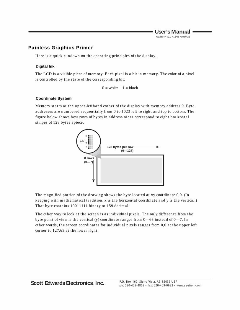
Painless Graphics Primer
Here is a quick rundown on the operating principles of the display.
Digital Ink
The LCD is a visible piece of memory. Each pixel is a bit in memory. The color of a pixel is controlled by the state of the corresponding bit:
0 = white 1 = black
Coordinate System
Memory starts at the upper-lefthand corner of the display with memory address 0. Byte addresses are numbered sequentially from 0 to 1023 left to right and top to bottom. The figure below shows how rows of bytes in address order correspond to eight horizontal stripes of 128 bytes apiece.
128 bytes per row
8 rows
0
7
bits
(0—127)
(0—7)
The magnified portion of the drawing shows the byte located at xy coordinate 0,0. (In keeping with mathematical tradition, x is the horizontal coordinate and y is the vertical.) That byte contains 10011111 binary or 159 decimal.
The other way to look at the screen is as individual pixels. The only difference from the byte point of view is the vertical (y) coordinate ranges from 0—63 instead of 0—7. In other words, the screen coordinates for individual pixels ranges from 0,0 at the upper left corner to 127,63 at the lower right.
User’s ManualG12864 • v2.0 • 11/98 • page 22
Scott Edwards Electronics, Inc. P.O. Box 160, Sierra Vista, AZ 85636 USAph: 520-459-4802 • fax: 520-459-0623 • www.seetron.com

Overlay Logic
The G12864 stores text and graphics in separate memory layers, then combines them for display on the screen. You can set the way that the layers are combined to achieve various visual effects. Here are the three options:
• OR Black text shows only when it overlays a white portion of the graphics layer.
• XOR Black text shows as the inverse of the graphics it overlays.
• AND Black text shows only when it overlays a black portion of the graphics layer.
To understand these options more completely, let’s look at how individual pixels from each layer would combine with each of the logic options.
Logic
OR
OR
OR
OR
XOR
XOR
XOR
XOR
AND
AND
AND
AND
GraphicsText Screen Remarks
0 OR 0 = 0
0 OR 1 = 1
1 OR 0 = 1
1 OR 1 = 1
0 XOR 0 = 0
0 XOR 1 =1
1 XOR 0 = 1
1 XOR 1 = 0
0 AND 0 = 0
0 AND 1 = 0
1 AND 0 = 0
1 AND 1 = 1
User’s ManualG12864 • v2.0 • 11/98 • page 23
Scott Edwards Electronics, Inc. P.O. Box 160, Sierra Vista, AZ 85636 USAph: 520-459-4802 • fax: 520-459-0623 • www.seetron.com

Creating and Downloading Bitmap Fonts and Graphics
The G12864 lets you create and download your own text font and graphics screens. Its 16kB of flash EEPROM stores the text font and up to 14 full-screen images. This memory is nonvolatile—it retains its contents even with power removed—but can be rewritten up to 100,000 times.
You can create fonts and images using standard PC-based graphics programs. Conversion and downloading utilities are included with the starter kit. The utilities handle graphics files in the following format:
• Windows bitmap (.BMP) format• Black and white only (1 bit per pixel)• No compression• 128 by 64 pixels
This file format is supported by the Windows Paint accessory included with both Windows 3.1 and 95/98. Many other graphics programs support this format as well. Here’s how to set up the Paint accessory:
• Pull down the Image menu and select Attributes. • Type in a Width of 128 and Height of 64. • Under Units click on Pels. • Under Colors click on Black and white. • When you’re done, click OK.
The Paint accessory is a good choice for creating and editing these images, because it lets you work pixel-by-pixel, and can display a grid and/or xy coordinates. You can import pictures from most other programs via cut and paste.
The disk that comes with the starter kit contains the standard font and a set of sample images. An easy way to get started is to open one of these files with Paint, modify it, and save it under a different file name.
Don’t use any other format or settings. Check the file size—it will be always be 1086 bytes for a 128x64 uncompressed black-and-white BMP file.
User’s ManualG12864 • v2.0 • 11/98 • page 24
Scott Edwards Electronics, Inc. P.O. Box 160, Sierra Vista, AZ 85636 USAph: 520-459-4802 • fax: 520-459-0623 • www.seetron.com
Installing and Using the Downloading Programs
The downloading programs are on the starter disk, or on the downloads page of www.seetron.com. These PC-based programs convert .BMP files to binary format and download them to your display via the serial port.
Windows 95 and 98, Drag-and-Drop
On the starter disk, open the folder DRAGDROP. You’ll see a series of files named BMP2COM#.EXE, where # represents the com port number the program uses. Pick the program whose # matches the com port you plan to use, and copy it to your hard drive. You may also drag the program icon to your Windows desktop to create a shortcut.
Set your display to 9600 bps and ESC/Ctl-Z to ESC. Connect it to the com port and power it up. Drag a .BMP file onto the BMP2COM# icon or shortcut. The file will be converted and downloaded to the display. Answer the on-screen prompts to transfer the picture to flash memory, if desired. [See note below about the PROT(ect) switch.]
Windows 3.1 and MS-DOS
On the starter disk, open the folder DOS. Copy the file BMPX.EXE to your hard drive. A good location is the directory (folder) named DOS, since this is where other DOS-related program and command files reside. A good second choice would be in the same directory as the .BMP file(s) that you plan to work with.
Connect the G12864 to a PC serial port (COM1 or COM2) and power it up. To download a .BMP file, get to the DOS prompt—by quitting Windows if needed—and type:
BMPX COM1 9600 filename{.BMP}
Substitute COM2 if you are using that port, and/or 2400 if your G12864 is set for that speed. If the file is in the current directory, then you may use just the file name. If it’s in a different directory, you must provide the complete path (e.g., C:\PAINT\MY_FONT1). Note that if the filename ends in .BMP, you may omit the file extension when typing the command.
The program will convert the bitmap file to the correct format for the G12864, then download it to the display. Answer the on-screen prompts to transfer the picture to flash memory.
The display will not transfer a picture to flash EEPROM if configuration switch 5 is set to PROT (write-protect). Turn off the display and change the switch setting before trying again. The software does not provide any error message when this occurs.
User’s ManualG12864 • v2.0 • 11/98 • page 25
Scott Edwards Electronics, Inc. P.O. Box 160, Sierra Vista, AZ 85636 USAph: 520-459-4802 • fax: 520-459-0623 • www.seetron.com

Font Structure
The text fonts are stored in the same format as normal full-screen images. The default 8x16-pixel font consists of two screens stored at flash memory locations 0 and 1. Each character occupies a specific 8- by 16-pixel rectangle of these screens as shown in the illustrations on pages 13 and 14.
If you want to use an additional font or fonts, just create more font pictures and store them in higher flash-memory locations. To switch to an alternative font, just send the appropriate ESC F(ont) instruction.
The optional 6x8-pixel font always resides at flash memory location 15. If you don’t want to use this font, you can place an ordinary full-screen graphic in this location, or use it as the second page of an alternative 8x16-pixel font.
If you create your own fonts, you should probably use the ones from the disk (files alpha0.bmp, alpha1.bmp, and alpha15.bmp) as starting points. Just open the appropriate file with Paint and make your changes.
User’s ManualG12864 • v2.0 • 11/98 • page 26
Scott Edwards Electronics, Inc. P.O. Box 160, Sierra Vista, AZ 85636 USAph: 520-459-4802 • fax: 520-459-0623 • www.seetron.com
Design Notes and Specifications
The G12864 is designed to speed prototyping and enable the creation of bench-top instruments requiring a serially driven text/graphics display. It is not meant for direct use by non-technical users or for incorporation into mass-produced consumer equipment. It has not been tested to EMC/EMI/ESD standards. (The same is true of most single-board computers and other subassemblies whose specs do not specifically include compliance data.) It is up to the purchaser to determine whether the G12864 is suitable for the intended use.
This unit is designed and manufactured to high standards of quality. This notice is simply intended to head off invalid assumptions that might affect decisions about using the G12864 in consumer products.
Maximum Ratings and Electrical Characteristics
The following data is preliminary and subject to change without notice. The G12864 consists of two subassemblies—an LCD graphics module, and a custom serial controller. Where the ratings of these two devices vary, the more conservative rating is shown in the table.
Parameter min max typical unitOperating temperature range 0.0 +50.0 — °C
+32.0 +122.0 — °F
Storage temperature range –20.0 +70.0 — °C–4.0 +158.0 — °F
Supply voltage to J1 (Vin) 7.0 10.0 9.0 Vdc6.0 8.0 7.0 Vac
Supply voltage to J2 (Vsupply) 4.5 5.5 5.0 VdcCurrent draw, backlight off — 25.0 15.0 mACurrent draw, backlight on — 100.0 75.0 mAInput voltage, serial 1 –15.0 +0.5 — VInput voltage, serial 0 3.0 15.0 — VOutput voltage, serial 1 –9.0 0.0 –5.0 VOutput voltage, serial 0 3.0 Vsupply 4.5 VProcessor clock speed — — 16.0 MHz
Maximum Execution Times for LCD Instructions
The following data is preliminary and subject to change without notice. Instructions not listed take less than 1 ms and therefore do not cause data to accumulate in the 64-byte buffer. All times are from entry of the last parameter to processing of the next instruction.
User’s ManualG12864 • v2.0 • 11/98 • page 27
Scott Edwards Electronics, Inc. P.O. Box 160, Sierra Vista, AZ 85636 USAph: 520-459-4802 • fax: 520-459-0623 • www.seetron.com

Instruction/action max
Display a text character 1.2 ms
Backspace (ASCII 8) 1.1 ms
Clear text (cntl-L) 15.0 ms
Clear graphics (ESC C) 15.0 ms
EEPROM screen (ESC E) 55.0 ms
Line plot (ESC L or ESC T) 10.0 ms
Transfer a screen to EEPROM (ESC X) 150.0 ms* Line plot time applies to version codes 030 and higher, which have been substantially improved over earlier versions.
Mechanical Specifications and Mounting
The LCD manufacturer’s drawing below provides the basic dimensions in millimeters. The serial interface is secured to the back of the display with 0.25" (6.4mm) standoff posts. On the screen side of the display, 0.375" (9.5mm) standoff posts with 2/56 threads permit the display to be mounted in a panel or enclosure.
Don’t remove the standoff posts that support the G12864 pcb. This could weaken or break the interface connections to the LCD.
User’s ManualG12864 • v2.0 • 11/98 • page 28
Scott Edwards Electronics, Inc. P.O. Box 160, Sierra Vista, AZ 85636 USAph: 520-459-4802 • fax: 520-459-0623 • www.seetron.com

Handling and Using Liquid Crystal Display Modules
LCDs can be damaged by careless handling. The manufacturer offers these suggestions for safe handling of LCDs:
• The LCD module and serial interface electronics use CMOS components and should be handled with appropriate antistatic precautions.
• Do not subject the LCD to temperatures outside its storage/operating ranges. Excessive heat or cold can degrade the polarizer, cause bubbles in the LCD material, or cause the polarizer to peel.
• Do not touch, push or rub the exposed polarizers (transparent screens) with anything harder than an HB pencil lead (glass, tweezers, etc.). Hard pressure on the screen may distort the liquid-crystal material. In some cases, the LCD will return to normal with time.
• When the display surface becomes dusty, wipe gently with absorbent cotton or other soft material like chamois soaked in petroleum benzine. Do not scrub hard or you may damage the display surface.
• Wipe off saliva or water immediately. Contact with water over a long period of time may cause deformation or color fading.
• Don’t allow the LCD to come into contact with oil and fats.
• Condensation on the surface and contact terminals due to cold will damage, stain or dirty the polarizers. After products are exposed to low temperatures they must be allowed to warm up before coming is contact with room-temperature air.
• Do not attach anything to the display screen. This may leave scratches or marks.
• Do not touch the display screen with bare hands. This will stain it. Skin oils and cosmetics are detrimental to the polarizers.
• Do not drop or jar the LCD module as you may crack or chip the glass.
User’s ManualG12864 • v2.0 • 11/98 • page 29
Scott Edwards Electronics, Inc. P.O. Box 160, Sierra Vista, AZ 85636 USAph: 520-459-4802 • fax: 520-459-0623 • www.seetron.com
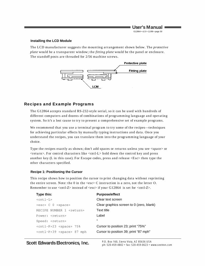
Installing the LCD Module
The LCD manufacturer suggests the mounting arrangement shown below. The protective plate would be a transparent window; the fitting plate would be the panel or enclosure. The standoff posts are threaded for 2/56 machine screws.
Recipes and Example Programs
The G12864 accepts standard RS-232-style serial, so it can be used with hundreds of different computers and dozens of combinations of programming language and operating system. So it’s a lost cause to try to present a comprehensive set of example programs.
We recommend that you use a terminal program to try some of the recipes—techniques for achieving particular effects by manually typing instructions and data. Once you understand the recipes, you can translate them into the programming language of your choice.
Type the recipes exactly as shown; don’t add spaces or returns unless you see <space> or <return>. For control characters like <cntl-L> hold down the control key and press another key (L in this case). For Escape codes, press and release <Esc> then type the other characters specified.
Recipe 1: Positioning the Cursor
This recipe shows how to position the cursor to print changing data without reprinting the entire screen. Note: the 0 in the <esc> C instruction is a zero, not the letter O. Remember to use <cntl-Z> instead of <esc> if your G12864 is set for <cntl-Z>.
Type this: Purpose/effect
<cntl-L> Clear text screen
<esc> C 0 <space> Clear graphics screen to 0 (zero, blank)
RECIPE NUMBER 1 <return> Text title
Power: <return> Label
Speed: <return> "
<cntl-P>23 <space> 75% Cursor to position 23; print “75%”
<cntl-P>39 <space> 87 mph Cursor to position 39; print “87 mph”
User’s ManualG12864 • v2.0 • 11/98 • page 30
Scott Edwards Electronics, Inc. P.O. Box 160, Sierra Vista, AZ 85636 USAph: 520-459-4802 • fax: 520-459-0623 • www.seetron.com
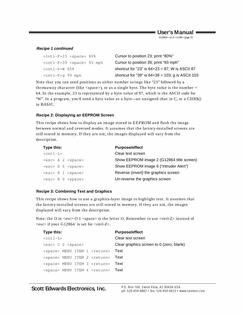
Recipe 1 continued
<cntl-P>23 <space> 80% Cursor to position 23; print “80%”
<cntl-P>39 <space> 93 mph Cursor to position 39; print “93 mph”
<cntl-P>W 85% shortcut for “23” is 64+23 = 87; W is ASCII 87
<cntl-P>g 99 mph shortcut for “39” is 64+39 = 103; g is ASCII 103
Note that you can send positions as either number strings like “23” followed by a throwaway character (like <space>), or as a single byte. The byte value is the number + 64. In the example, 23 is represented by a byte value of 87, which is the ASCII code for “W”. In a program, you’d send a byte value as a byte—an unsigned char in C, or a CHR$() in BASIC.
Recipe 2: Displaying an EEPROM Screen
This recipe shows how to display an image stored in EEPROM and flash the image between normal and reversed modes. It assumes that the factory-installed screens are still stored in memory. If they are not, the images displayed will vary from the description.
Type this: Purpose/effect
<cntl-L> Clear text screen
<esc> E 2 <space> Show EEPROM image 2 (G12864 title screen)
<esc> E 6 <space> Show EEPROM image 6 (“Intruder Alert”)
<esc> R 1 <space> Reverse (invert) the graphics screen
<esc> R 0 <space> Un-reverse the graphics screen
Recipe 3: Combining Text and Graphics
This recipe shows how to use a graphics-layer image to highlight text. It assumes that the factory-installed screens are still stored in memory. If they are not, the images displayed will vary from the description.
Note: the O in <esc> O 1 <space> is the letter O. Remember to use <cntl-Z> instead of <esc> if your G12864 is set for <cntl-Z>.
Type this: Purpose/effect
<cntl-L> Clear text screen
<esc> C 0 <space> Clear graphics screen to 0 (zero, blank)
<space> MENU ITEM 1 <return> Text
<space> MENU ITEM 2 <return> Text
<space> MENU ITEM 3 <return> Text
<space> MENU ITEM 4 <return> Text
User’s ManualG12864 • v2.0 • 11/98 • page 31
Scott Edwards Electronics, Inc. P.O. Box 160, Sierra Vista, AZ 85636 USAph: 520-459-4802 • fax: 520-459-0623 • www.seetron.com
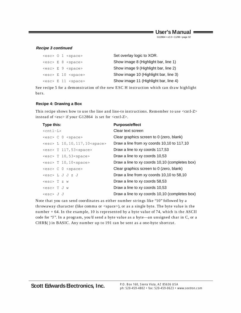
Recipe 3 continued
<esc> O 1 <space> Set overlay logic to XOR.
<esc> E 8 <space> Show image 8 (Highlight bar, line 1)
<esc> E 9 <space> Show image 9 (Highlight bar, line 2)
<esc> E 10 <space> Show image 10 (Highlight bar, line 3)
<esc> E 11 <space> Show image 11 (Highlight bar, line 4)
See recipe 5 for a demonstration of the new ESC H instruction which can draw highlight bars.
Recipe 4: Drawing a Box
This recipe shows how to use the line and line-to instructions. Remember to use <cntl-Z> instead of <esc> if your G12864 is set for <cntl-Z>.
Type this: Purpose/effect
<cntl-L> Clear text screen
<esc> C 0 <space> Clear graphics screen to 0 (zero, blank)
<esc> L 10,10,117,10<space> Draw a line from xy coords 10,10 to 117,10
<esc> T 117,53<space> Draw a line to xy coords 117,53
<esc> T 10,53<space> Draw a line to xy coords 10,53
<esc> T 10,10<space> Draw a line to xy coords 10,10 (completes box)
<esc> C 0 <space> Clear graphics screen to 0 (zero, blank)
<esc> L J J z J Draw a line from xy coords 10,10 to 58,10
<esc> T z w Draw a line to xy coords 58,53
<esc> T J w Draw a line to xy coords 10,53
<esc> J J Draw a line to xy coords 10,10 (completes box)
Note that you can send coordinates as either number strings like “10” followed by a throwaway character (like comma or <space>), or as a single byte. The byte value is the number + 64. In the example, 10 is represented by a byte value of 74, which is the ASCII code for “J”. In a program, you’d send a byte value as a byte—an unsigned char in C, or a CHR$( ) in BASIC. Any number up to 191 can be sent as a one-byte shortcut.
User’s ManualG12864 • v2.0 • 11/98 • page 32
Scott Edwards Electronics, Inc. P.O. Box 160, Sierra Vista, AZ 85636 USAph: 520-459-4802 • fax: 520-459-0623 • www.seetron.com
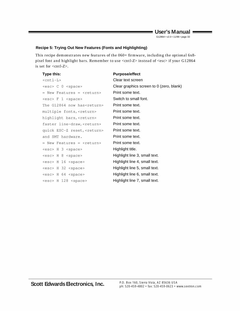
Recipe 5: Trying Out New Features (Fonts and Highlighting)
This recipe demonstrates new features of the 060+ firmware, including the optional 6x8-pixel font and highlight bars. Remember to use <cntl-Z> instead of <esc> if your G12864 is set for <cntl-Z>.
Type this: Purpose/effect
<cntl-L> Clear text screen
<esc> C 0 <space> Clear graphics screen to 0 (zero, blank)
= New Features = <return> Print some text.
<esc> F 1 <space> Switch to small font.
The G12864 now has<return> Print some text.
multiple fonts,<return> Print some text.
highlight bars,<return> Print some text.
faster line-draw,<return> Print some text.
quick ESC-Z reset,<return> Print some text.
and SMT hardware. Print some text.
= New Features = <return> Print some text.
<esc> H 3 <space> Highlight title.
<esc> H 8 <space> Highlight line 3, small text.
<esc> H 16 <space> Highlight line 4, small text.
<esc> H 32 <space> Highlight line 5, small text.
<esc> H 64 <space> Highlight line 6, small text.
<esc> H 128 <space> Highlight line 7, small text.
User’s ManualG12864 • v2.0 • 11/98 • page 33
Scott Edwards Electronics, Inc. P.O. Box 160, Sierra Vista, AZ 85636 USAph: 520-459-4802 • fax: 520-459-0623 • www.seetron.com

Example Program 1: PC Running QBASIC or QuickBASIC' Program: QGXDEMO.BAS (QBASIC/QuickBASIC Demo of G12864)' This program demonstrates the G12864 Serial Graphics LCD' from Scott Edwards Electronics Inc. with QBASIC or QuickBASIC.' Configure the G12864 for 9600 baud (config switch 2 ON) and' escape codes (config switch 4 OFF). Connect power and serial' input. This program uses COM1--change the "OPEN" instruction if' you're using COM2.
'===============Delay Subroutine using Nulls====================DECLARE SUB pause (time AS INTEGER)DEFINT A-Z
'===========Constants Defining LCD Instructions=================' These constants assign names to the LCD instructions. The' numbers are the ASCII values listed in the manual. For example,' cntl-L is the clear-screen instruction; the ASCII value is 12.' So printing CHR$(12) to the LCD clears the screen.CONST clrTXT = 12 ' Cntl-L: clear the text layer.CONST bksp = 8 ' Backspace.CONST posCmd = 16 ' Position the cursor.CONST ESC = 27 ' Escape code.
'==================Demonstration Program=======================' Set up serial port COM1; disable handshaking (CD, CS, DS, OP).OPEN "COM1:9600,N,8,1,CD0,CS0,DS0,OP0" FOR OUTPUT AS #1' ===========' ==Recipe 1' ===========' This code works the same as recipe 1 from the G12864 manual.' It clears the screen, prints some text, then positions the' cursor to change just portions of the text. Notice that some' PRINT statements end in semicolons (;) and others don't. PRINT' normally adds a carriage return to all data. When you don't want' a return (as when you send instructions), adding a semicolon' prevents it.PRINT #1, CHR$(clrTXT); ' Clear text layer.PRINT #1, CHR$(ESC); "C0."; ' Clear graphics layer.PRINT #1, "RECIPE NUMBER 1" ' Print the title, followed by return.PRINT #1, "Power:" ' Print label, followed by return.PRINT #1, "Speed:" ' " "' Here's the cursor-positioning command. This PRINT statement combines' the command with the text to be printed. Notice that there's a' throwaway character (.) separating the number (23) from the text "75".' You could use any character except null (ASCII 0) in that position.PRINT #1, CHR$(posCmd); "23.75%"; ' Go to position 23, print "75%"PRINT #1, CHR$(posCmd); "39.87mph"; ' Go to position 39, print "87mph"SLEEP 2 ' Delay for 2 seconds.
User’s ManualG12864 • v2.0 • 11/98 • page 34
Scott Edwards Electronics, Inc. P.O. Box 160, Sierra Vista, AZ 85636 USAph: 520-459-4802 • fax: 520-459-0623 • www.seetron.com

' Here is the other way to send position values--as single bytes with' no throwaway. Just add 64 to the position, and send that as a CHR$(),' which is just BASIC's term for a byte. The G12864 will accept _any_' number in this shorthand, so it's a valuable technique to learn.PRINT #1, CHR$(posCmd); CHR$(64 + 23); "80%"; ' Pos 23, print "80%"PRINT #1, CHR$(posCmd); CHR$(64 + 39); "93mph"; ' Pos 39, print "93mph"' Here's a looped version with variables. Note that when BASIC formats a' variable as text--as when you PRINT a variable like power--it adds spaces' before and after. If you don't like the spaces, convert the value to' a string with STR$() and use LTRIM$() and/or RTRIM$() to trim spaces.' See the BASIC docs for more info.pwrPos = 64 + 23 ' Position of the power data.spdPos = 64 + 39 ' Position of the speed data.FOR power = 50 TO 85 STEP 5 SLEEP 1 PRINT #1, CHR$(posCmd); CHR$(pwrPos); power; "%"; speed = power * 1.2 ' Phoney calculation. PRINT #1, CHR$(posCmd); CHR$(spdPos); speed; "mph"NEXT' ===========' ==Recipe 2' ===========' Recipe 2 shows how to display EEPROM screens.PRINT #1, CHR$(clrTXT); ' Clear text layer.PRINT #1, CHR$(ESC); "E2."; ' Display EPROM image #2.SLEEP 2 ' Delay 2 seconds.PRINT #1, CHR$(ESC); "C0."; ' Clear graphics layer.PRINT #1, CHR$(ESC); "E6."; ' Display EPROM image #6.FOR flashes = 1 TO 3 SLEEP 1 PRINT #1, CHR$(ESC); "R1."; ' Reverse graphics. SLEEP 1 PRINT #1, CHR$(ESC); "R0."; ' Normal graphics.NEXTSLEEP 2 ' Pause 2 seconds.' ===========' ==Recipe 3' ===========' Recipe 3 shows a useful technique for combining text and graphics to' selectively highlight portions of the text.PRINT #1, CHR$(clrTXT); ' Clear text layer.PRINT #1, CHR$(ESC); "C0."; ' Clear graphics layer.PRINT #1, " Menu Item 1" ' Display text, followed by return.PRINT #1, " Menu Item 2" ' "PRINT #1, " Menu Item 3" ' "PRINT #1, " Menu Item 4" ' "PRINT #1, CHR$(ESC); "O1."; ' Set (O)verlay to 1 (XOR).FOR selection = 8 TO 11 ' EEPROM screens 8-11 are highlight bars. SLEEP 1 ' Pause 1 second.
User’s ManualG12864 • v2.0 • 11/98 • page 35
Scott Edwards Electronics, Inc. P.O. Box 160, Sierra Vista, AZ 85636 USAph: 520-459-4802 • fax: 520-459-0623 • www.seetron.com

hilite = selection + 64 ' One-byte shortcut for selection. PRINT #1, CHR$(ESC); "E"; CHR$(hilite); ' Show selection screen.NEXTSLEEP 2 ' Pause 2 seconds.' ===========' ==Recipe 4' ===========' This code draws a box on the screen with the line and line-to' commands. It's a little different from the recipe in the manual' in that it uses only shortcut numbers instead of numeric text.PRINT #1, CHR$(clrTXT); ' Clear text layer.PRINT #1, CHR$(ESC); "C0."; ' Clear graphics layer.x1 = 10 + 64: y1 = 10 + 64 ' 1st point (64 added to make shortcuts)x2 = 117 + 64: y2 = 10 + 64 ' 2nd point.' Here's the line command in the form <esc> L x1 y1 x2 y2PRINT #1, CHR$(ESC); "L"; CHR$(x1); CHR$(y1);PRINT #1, CHR$(x2); CHR$(y2);' Now we can use line-to commands. This draws a line that starts' from the endpoint of the previous line.y2 = 53 + 64 ' New y coordinatePRINT #1, CHR$(ESC); "T"; CHR$(x2); CHR$(y2);x2 = 10 + 64 ' New x coordinatePRINT #1, CHR$(ESC); "T"; CHR$(x2); CHR$(y2);y2 = 10 + 64 ' New y coordinatePRINT #1, CHR$(ESC); "T"; CHR$(x2); CHR$(y2);SLEEP 2' ===========' ==Recipe 5' ===========' This code demonstrates the new features of firmware version 060 and' higher, included in the surface-mount version 2.0 hardware or' available as an upgrade to older units. A small (6x8-pixel) font' image must be installed in flash EEPROM screen 15 for this to' work properly.PRINT #1, CHR$(clrTXT); ' Clear text layer.PRINT #1, CHR$(ESC); "C0."; ' Clear graphics layer.PRINT #1, "= New Features ="; ' Print banner in default font.PRINT #1, CHR$(ESC); "F1."; ' Switch to small font.PRINT #1, "The G12864 now has" ' Print messages in small font.PRINT #1, " multiple fonts, "PRINT #1, " highlight bars, "PRINT #1, " faster line-draw,"PRINT #1, " quick ESC-Z reset,"PRINT #1, " and SMT hardware.";
User’s ManualG12864 • v2.0 • 11/98 • page 36
Scott Edwards Electronics, Inc. P.O. Box 160, Sierra Vista, AZ 85636 USAph: 520-459-4802 • fax: 520-459-0623 • www.seetron.com
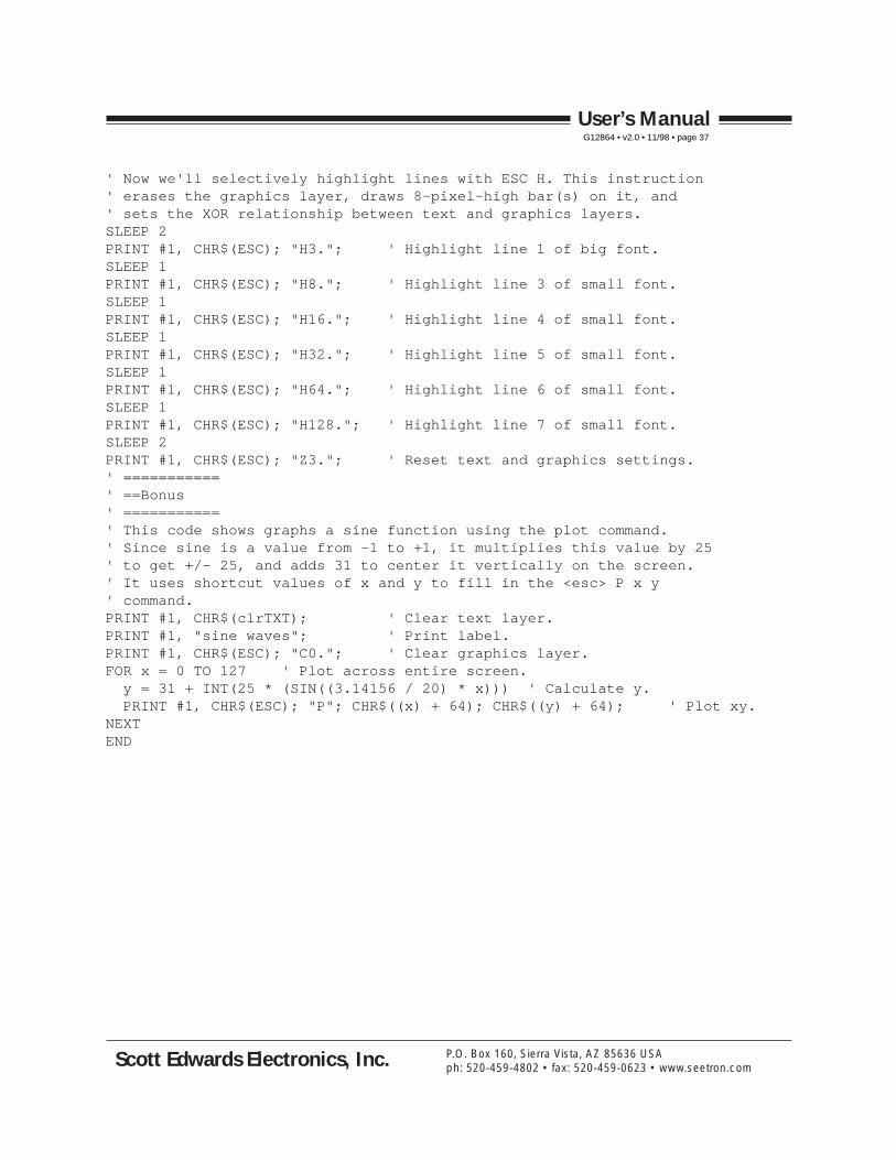
' Now we'll selectively highlight lines with ESC H. This instruction' erases the graphics layer, draws 8-pixel-high bar(s) on it, and' sets the XOR relationship between text and graphics layers.SLEEP 2PRINT #1, CHR$(ESC); "H3."; ' Highlight line 1 of big font.SLEEP 1PRINT #1, CHR$(ESC); "H8."; ' Highlight line 3 of small font.SLEEP 1PRINT #1, CHR$(ESC); "H16."; ' Highlight line 4 of small font.SLEEP 1PRINT #1, CHR$(ESC); "H32."; ' Highlight line 5 of small font.SLEEP 1PRINT #1, CHR$(ESC); "H64."; ' Highlight line 6 of small font.SLEEP 1PRINT #1, CHR$(ESC); "H128."; ' Highlight line 7 of small font.SLEEP 2PRINT #1, CHR$(ESC); "Z3."; ' Reset text and graphics settings.' ===========' ==Bonus' ===========' This code shows graphs a sine function using the plot command.' Since sine is a value from -1 to +1, it multiplies this value by 25' to get +/- 25, and adds 31 to center it vertically on the screen.' It uses shortcut values of x and y to fill in the <esc> P x y' command.PRINT #1, CHR$(clrTXT); ' Clear text layer.PRINT #1, "sine waves"; ' Print label.PRINT #1, CHR$(ESC); "C0."; ' Clear graphics layer.FOR x = 0 TO 127 ' Plot across entire screen. y = 31 + INT(25 * (SIN((3.14156 / 20) * x))) ' Calculate y. PRINT #1, CHR$(ESC); "P"; CHR$((x) + 64); CHR$((y) + 64); ' Plot xy.NEXTEND
User’s ManualG12864 • v2.0 • 11/98 • page 37
Scott Edwards Electronics, Inc. P.O. Box 160, Sierra Vista, AZ 85636 USAph: 520-459-4802 • fax: 520-459-0623 • www.seetron.com
Example Program 2: BASIC Stamp II' Program: GXDEMO.BS2 (Demonstrate G12864 Serial Graphics LCD)' This program demonstrates many of the features of the G12864' Serial Graphics LCD Module from Scott Edwards Electronics.' Set the module to 9600 bps (config switch 2 ON/right).' Make sure that ESC/ctl-Z is set to ESC (config 4 OFF/left).' Connect the serial input of the module (J3 pin marked SER)' to BS2 pin P0, GND to GND and +5V to +5V. Alternatively, you can' omit the +5V connection and run the G12864 off its AC adapter.' ======IMPORTANT====== If you run the G12864 off the BS2's 5V' regulator, do not turn on the backlight. The BS2 regulator' cannot supply enough current to power it.
' =========Define names for LCD instructions, bps=======LCD con 0 ' Output pin to LCD.clrLCD con 12 ' Clear LCD text screen.posCmd con 16 ' Position cursor.N9600 con $4054 ' Baudmode for inverted, 9600-bps output.N2400 con $418d ' Baudmode for inverted, 2400-bps.ESC con 27 ' Escape character.' Note: the constant "CR" for carriage return is predefined in the BS2.
' =====================Define variables==================counter var byte ' Byte counter for miscellaneous purposes.sinX var byte ' Sine of x used in sine-plot demo.
' ===========Recipe #1, positioning the cursor===========pause 1000serout LCD,N9600,[ESC,"C0 "] ' Clear graphics screenserout LCD,N9600,[clrLCD,"RECIPE NUMBER 1",cr] ' Clear screen, show text.serout LCD,N9600,["Power:",cr,"Speed:"] ' More text.' The following lines position the cursor by sending the positioning' command, followed by a decimal number (e.g., DEC 23) and a space' (throwaway character). This is the same way you would type the command.serout LCD,N9600,[posCmd,DEC 23," 65%"] ' Move to pos 23, print 65%serout LCD,N9600,[posCmd,DEC 39," 70mph"] ' Pos 39, print 70mph' Within programs, there's a better way to send numbers--just add 64' to the desired value and send that as a single byte. Since a byte' can hold up to 255, you can send any value from 0 to 191 with this' technique.FOR counter = 70 TO 100 STEP 5
pause 1000 ' Wait a second. serout LCD,N9600,[posCmd,(64+23)] ' Move to pos 23 by 1-byte method. serout LCD,N9600,[DEC counter,"%"] ' Print the count there. serout LCD,N9600,[posCmd,(64+39), DEC (counter+5),"mph"] ' Pos 39, text.NEXTpause 2000 ' Wait 2 seconds.serout LCD, N9600, [clrLCD] ' Clear text screen.
User’s ManualG12864 • v2.0 • 11/98 • page 38
Scott Edwards Electronics, Inc. P.O. Box 160, Sierra Vista, AZ 85636 USAph: 520-459-4802 • fax: 520-459-0623 • www.seetron.com
' ===========Recipe #2, Displaying an EEPROM screen===========serout LCD,N9600,[ESC,"E2 "] ' Display EEPROM screen 2.pause 2000 ' Wait 2 secs.serout LCD,N9600,[ESC,"C0 "] ' Clear the graphics screen.pause 1000 ' Wait 1 sec.serout LCD,N9600,[ESC,"E",(64+6)] ' Show screen 6 using 1-byte #.' The loop below flashes the graphics screen by alternating bewtween' reverse and normal video. The (R)everse command is sent as text--' ESC,"R1 "--and using the one-byte shortcut for 0, ESC,"R",64.FOR counter = 1 TO 3 ' Flash the screen 3 times.
pause 1000 ' Wait 1 sec. serout LCD,N9600,[ESC,"R1 "] ' Reverse (invert) the graphics screen.
pause 1000 ' Wait 1 sec. serout LCD,N9600,[ESC,"R",64] ' Un-invert graphics (ESC R 0).NEXTpause 1000 ' Wait 1 sec.serout LCD,N9600,[ESC,"C",64] ' Clear the graphics screen.
' ===========Recipe #3, Combining text and graphics===========pause 2000 ' Wait 2 secs.FOR counter = 1 TO 4 ' On each of the 4 lines, serout LCD,N9600,[" Menu Item ",DEC counter,cr] ' Print items 1-4.NEXTserout LCD,N9600,[ESC,"O1 "] ' Set (O)verlay to XOR (1).' The following loop calls up screens 8 through 11, which selectively' highlight lines of text.FOR counter = 8 TO 11 pause 1000 ' Wait 1 sec. serout LCD,N9600,[ESC,"E",(64+counter)] ' Show screen spcified byNEXT ' value of counter (8-11).
' =================Recipe #4, Drawing a box================pause 2000 ' Wait 2 secs.serout LCD,N9600,[clrLCD,ESC,"C",64] ' Clear text & graphics screens.' The (L)ine command below draws a line from xy coordinates 10,10 to' 117,10. It uses shortcut numbers (64+value) to keep thing concise.serout LCD,N9600,[ESC,"L",74,74,181,74] ' Draw 1st line.' When you draw a line, the G12864 stores the xy coordinates of the end' point. In this case, that would be 117,10. If you want to draw another' line starting from that point, you can use the line(T)o command. The' next instruction draws a line to 117,53:serout LCD,N9600,[ESC,"T",181,117] ' Draw line to 117,53.' To finish the box, we'll combine two more line(T)os into one' Serout.serout LCD,N9600,[ESC,"T",74,117,ESC,"T",74,74]
User’s ManualG12864 • v2.0 • 11/98 • page 39
Scott Edwards Electronics, Inc. P.O. Box 160, Sierra Vista, AZ 85636 USAph: 520-459-4802 • fax: 520-459-0623 • www.seetron.com

' ===========Recipe #5, Demonstrate New Features============pause 2000 ' Wait 2 secs.serout LCD,N9600,[clrLCD,ESC,"C",64] ' Clear text & graphics screens.serout LCD,N9600,["= New Features ="] ' Print banner in std font. serout LCD,N9600,[ESC,"F",65] ' Switch to small font. serout LCD,N9600,["The G12864 now has",CR] ' Print feature list.serout LCD,N9600,["multiple fonts,",CR]serout LCD,N9600,["highlight bars,",CR]serout LCD,N9600,["faster line-draw,",CR]serout LCD,N9600,["quick ESC-Z reset,",CR]serout LCD,N9600,["and SMT hardware."]' Now selectively highlight lines with ESC-H. This erases the ' graphics layer and draws 8-pixel-high bars. Note that we're ' using one-byte shortcuts for the ESC-H arguments. pause 2000 ' Wait 2 secs. serout LCD,N9600,[ESC,"H",67] ' Highlight line 1 of big font. pause 1000serout LCD,N9600,[ESC,"H",72] ' Highlight line 3 of small font. pause 1000serout LCD,N9600,[ESC,"H",80] ' Highlight line 4 of small font. pause 1000serout LCD,N9600,[ESC,"H",96] ' Highlight line 5 of small font. pause 1000serout LCD,N9600,[ESC,"H",128] ' Highlight line 6 of small font. pause 1000serout LCD,N9600,[ESC,"H",192] ' Highlight line 7 of small font. pause 2000serout LCD,N9600,[ESC,"Z",67] ' Reset text and graphics layers.
' ================Bonus, Plotting a sinewave==============serout LCD,N9600,[clrLCD,ESC,"C",64] ' Clear text & graphics.' The loop below displays several cycles of a sine wave using the' BS2's SIN function. It plots the wave centered vertically on the' screen (above and below y coord 32).FOR counter = 0 TO 127
sinX = 32 + ((SIN(8 * counter)) / 8) serout LCD,N9600,[ESC,"P",(64+counter),(64+sinX)]NEXTSTOP ' Demo over.
User’s ManualG12864 • v2.0 • 11/98 • page 40
Scott Edwards Electronics, Inc. P.O. Box 160, Sierra Vista, AZ 85636 USAph: 520-459-4802 • fax: 520-459-0623 • www.seetron.com