user’s handbook analog synthesized microwave radio … · ii.2 – w orking climatic conditions...
TRANSCRIPT

EK-ESXG/11 – EK-ESXG/12 – EK-ESXG/13 Rev. B of 16/10/2006
Sh. 1 of 51
MAN2_14G_EXT_ENG_SINT.doc
Eurotek s.r.l.
User’s handbook Analog Synthesized
Microwave Radio Links
EK-ES2G/13 EK-ES5G/12
EK-ES7G/12 EK-ES10G/11
EK-ES12G/11 EK-ES13G/11
EK-ES14G/11
EK-ESXG/11 – EK-ESXG/12 – EK-ESXG/13 Rev. B of 16/10/2006
Sh. 2 of 51
MAN2_14G_EXT_ENG_SINT.doc
Eurotek s.r.l.
Warning!
The socket utilized for the unit power-supply must have the appropriate ground conductor.
The connection of the unit , to a socket without the ground conductor, will keep the whole equipment dangerous for people safety.
About the repair of the units refer to specialized personnel only .
Inside the apparatus there are voltages which could be dangerous for person.
Before opening the cover, switch off the unit, disconnect the connection and the supply cable.
In case of electrical shock follow the instructions of first aid collected on page 3
Substitute the fuses interrupted with others of the same type and value.
The waste disposal of the devices must be executed in the respect of the enforced laws in the country uses.
Eurotek not assumed responsibility for waste disposal in contrast with enforced laws.
LIFE SUPPORT APPLICATIONS. Eurotek’s products are not designed for use as critical components in life support devices or system without the express written approval of the Eurotek S.r.l. As used herein.
- Life support devices or system are devices or system which, (a) are intended for surgical implant into the body, or (b) support or sustain life, and whose failure to perform, when properly used in accordance with instructions for use provided in the labeling, can be reasonably expected to result in a significant injury to the user.
- A critical component is any component of a life support device or system whose failure to perform can be reasonably expected to cause the failure of the life support device or system, or to affect its safety or effectiveness.
The information given in this documentation could have variations without forewarning. The firm Eurotek S.r.l. does not give any guaranty about this documentation. The firm Eurotek S.r.l. does not consider itself responsible for the possible mistakes which could be present in this documentation.

EK-ESXG/11 – EK-ESXG/12 – EK-ESXG/13 Rev. B of 16/10/2006
Sh. 3 of 51
MAN2_14G_EXT_ENG_SINT.doc
Eurotek s.r.l.
First aid: artificial breathing(mouth to mouth) 1
In case of electric shock you have to ensure the first aids to the patient, but to do this you have to consider two very important things: - interrupt immediately the electric circuit; - until the circuit has not been interrupted, do not touch the patient with bare hands; After doing this, without delay contact the nearest mobile unit of first aid and practice to the patient, in case of loss of consciousness, the breathing mouth to mouth is described following.
2
- Put the patient lying on his back with the arms parallel to the body, ensure that he does not have the breathing tracts obstructed (chewing-gum, dental prosthesis, etc.), otherwise set him free from foreign bodies. -Kneel near the patient’s head and putting a hand under his neck, incline as possible the head backwards.
3
- Going on with keeping the patient’s head inclined with a hand, use the other one to occlude the nostrils, if the breathing is done through the oral cavity, or the mouth if you want to do it through the nasal cavity. - While you are doing these steps begin with deep breathing in the auto oxygenation - Then practice the artificial breathing blowing in the chosen cavity beginning with ten expirations each minute to go on with twelve and fifteen.
4
- During the execution of breathing you have to control observing that the patient’s chest dilates, otherwise change cavity in which you blow the air because it could be obstructed.
5
Do not ever stop the artificial breathing until the patient has recovered or has come the first aid unit.

EK-ESXG/11 – EK-ESXG/12 – EK-ESXG/13 Rev. B of 16/10/2006
Sh. 4 of 51
MAN2_14G_EXT_ENG_SINT.doc
Eurotek s.r.l.
I – GENERAL NOTES ............................................................................................. 7
I.1 – DEVICE COMPOSITION 2-5-7GHZ .............................................................................................8
I.2 – DEVICE COMPOSITION 10-12 GHZ ...........................................................................................9
I.3 – DEVICE COMPOSITION 13-14 GHZ .........................................................................................10
II - CHARACTERISTICS.................................................................................... 11
II.1 – NET SECTION PERFORMANCES:..............................................................................................11
II.2 – WORKING CLIMATIC CONDITIONS FOR INDOOR UNIT (IDU): ................................................12
II.3 – WORKING CLIMATIC CONDITIONS FOR OUTDOOR UNIT (ODU): ...........................................12
II.4 – POWER SUPPLIES:..................................................................................................................12
II.5 – MECHANICAL SPECIFICATIONS:.............................................................................................13
III –DESCRIPTION................................................................................................ 14
III.1 – FRONT VIEW OF TRANSMITTING IDU: ..................................................................................14
III.2 – DESCRIPTION OF TRANSMITTER IDU FRONT-PANEL: ............................................................14
III.3 – FRONT VIEW OF RECEIVING IDU: .........................................................................................15
III.4 – DESCRIPTION OF RECEIVING IDU FRONT-PANEL: .................................................................15
III.5 – BACK VIEW OF TRANSMITTING IDU:....................................................................................16
III.6 – DESCRIPTION OF CONNECTIONS ON THE BACK-PANEL OF THE TRANSMITTING IDU: .............16
III.7 – BACK VIEW OF RECEIVING IDU: ..........................................................................................17
III.8 - DESCRIPTION OF CONNECTIONS ON THE BACK-PANEL OF THE RECEIVING IDU: ....................17
III.9 - MEASURES THAT CAN BE CARRIED OUT WITH TRANSMITTING IDU DEVICE INDICATOR: .....18
III.10 - POSITION DIAGRAM OF JUMPERS ON THE TRANSMITTING IDU: .........................................19
III.11 - INTERNAL LAY -OUT OF TRANSMITTING IDU: ....................................................................20
III.12 - MEASURES THAT CAN BE CARRIED OUT WITH RECEIVING IDU DEVICE INDICATOR:..........20
III.12 - MEASURES THAT CAN BE CARRIED OUT WITH RECEIVING IDU DEVICE INDICATOR:..........21
III.13 - POSITION DIAGRAM OF JUMPERS ON THE RECEIVING IDU:................................................22
III.14 - INTERNAL LAY -OUT OF RECEIVING IDU: ..........................................................................23
INDEX

EK-ESXG/11 – EK-ESXG/12 – EK-ESXG/13 Rev. B of 16/10/2006
Sh. 5 of 51
MAN2_14G_EXT_ENG_SINT.doc
Eurotek s.r.l.
III.15 - REAR DESCRIPTION SUITABLE FOR RECEIVING AND TRANSMITTING ODU: ....................... 23
III.15 - REAR DESCRIPTION SUITABLE FOR RECEIVING AND TRANSMITTING ODU: ....................... 24
III.16 - MEASUREMENT UNIT EK-TMS/1 DESCRIPTION: .............................................................. 25
IV - MOUNTING INSTRUCTIONS....................................................................26
IV.1 - ODU ASSEMBLING AND SUPPLY CONFIGURATION: ............................................................ 26
IV.2 - ODU ASSEMBLING CONFIGURATION IN MOBILE POST: ....................................................... 27
Side view: ................................................................................................................................................................27 Rear view (fully assembled): ...................................................................................................................................28
IV.3 - ODU IN RESIDENT POST ASSEMBLING CONFIGURATION WITH PARABOLIC REFLECTOR:...... 30
IV.4 - ODU IN RESIDENT POST ASSEMBLING CONFIGURATION WITHOUT PARABOLIC REFLECTOR:33
IV.5 - POINTING PROCEDURE OF PARABOLIC REFLECTOR IN MOBILE POST CONFIGURATION:........ 36
IV.6 - POINTING PROCEDURE OF PARABOLIC REFLECTOR IN RESIDENT POST CONFIGURATION:..... 36
V - WORKING DESCRIPTION..........................................................................37
V.1 – IDU-ODU TRANSMITTING BLOCK DIAGRAM:....................................................................... 37
V.2 – TRANSMITTING WORKING DESCRIPTION (EK-ES2G/13; EK-ES5G/12; EK-ES7G/12): ...... 38
V.3 – IDU-ODU RECEIVING BLOCK DIAGRAM: ............................................................................. 39
V.4 - RECEIVING WORKING DESCRIPTION (EK-ES2G/13; EK-ES5G/12; EK-ES7G/12):..............40
V.5 – IDU-ODU TRANSMITTING BLOCK DIAGRAM:....................................................................... 41
V.6 – TRANSMITTING WORKING DESCRIPTION (EK-ES10G/11, EK-ES12G/11, EK-ES13G/11
EK-ES14G/11,): ........................................................................................................................... 42
V.7 – IDU-ODU RECEIVING BLOCK DIAGRAM: ............................................................................ 43
V.8 – RECEIVING WORKING DESCRIPTION (EK-ES10G/11, EK-ES12G/11, EK-ES13G/11
EK-ES14G/11,): ........................................................................................................................... 44
VI - INSTALLATION ARRANGEMENTS................... .....................................45
VI.1 – THERMAL DISSIPATION: ...................................................................................................... 45
VI.2 – PINS OF TELECONTROL CONNECTOR:................................................................................... 45
VI.3 – ODU IDU CONNECTION .................................................................................................... 46
VI.3 – ODU IDU CONNECTION .................................................................................................... 47

EK-ESXG/11 – EK-ESXG/12 – EK-ESXG/13 Rev. B of 16/10/2006
Sh. 6 of 51
MAN2_14G_EXT_ENG_SINT.doc
Eurotek s.r.l.
VII - CANALIZATION ........................................................................................ 47
VII.1 - EK-ES2G/13......................................................................................................................47
VII.2 - EK-ES5G/12......................................................................................................................47
VII.3 - EK-ES7G/12......................................................................................................................48
VII.4 -EK-ES10G/11.....................................................................................................................48
VII.5 -EK-ES12G/11.....................................................................................................................49
VII.6 -EK-ES14G/11.....................................................................................................................49
VII.7 -EK-ES13G/11.....................................................................................................................50

EK-ESXG/11 – EK-ESXG/12 – EK-ESXG/13 Rev. B of 16/10/2006
Sh. 7 of 51
MAN2_14G_EXT_ENG_SINT.doc
Eurotek s.r.l.
I – GENERAL NOTES The radio links in frequency modulation EK-ESxG/11 EK-ESxG/12 EK-ESxG/13 have been designed and realized to have audio-video connections point to point. The selectivity of the apparatus is guaranteed by working in double frequency convertion (triple for EK-ES10G/11, EK-ES12G/11, EK-ES13G/11, EK-ES14G/11), with first intermediate frequency at 1000 MHz (EK-ES2G/13, EK-ES10G/11, EK-ES12G/11, EK-ES13G/11, EK-ES14G/11); 1189 MHz (EK-ES5G/12); 1540 MHz (EK-ES7G/12), obtained using auto-tuning oscillators to improve frequency stability, and by the use of STRIPLINE filters and Surface Acoustic Wave (SAW) filters. The main requirements of the user which utilizes a radio link telecommunication system are the availability on time of the connection and naturally its quality : - the necessity to be able to have reliable connections is ensured through the use of quality components and of solid state devices (in detail GaAs) for microwave parts (the low noise preamplifier uses last generation HEMT devices), the only components with mechanical motion parts are the relays used for monitoring guarantying the necessary galvanic insulation; the design of the apparatus has been moreover oriented to determine working points for the different devices which keep themselves in electrical and climatic conditions well inside the guaranteed working limits. - the quality of signals taken by the radio links EK-ESxG/11 EK-ESxG/12 EK-ESxG/13 is defined by chosen components which exploit completely the latest technologies as for the amplification chains at solid state as for conversion devices; the inevitable phase distortions due to filters, necessarily put on signals way, have been balanced with suitable equalizers partially accessible from outside. Expressly realized following the recommendations of CCIR and Ministry of Communications Superior Institute of communications and information technologies, the frequency modulation radio links EK-ESxG/11 EK-ESxG/12 EK-EsxG/13, give an interconnection with different devices and with existing communication nets respecting levels, modulations and impedances. The modem circuits have been made using PLL (phase locked loop) technique which consent working stability over wide thermal excursions, while the employment of many integrated circuits rather than discrete components reduce the units encumbrance and consumption. A particular care has been taken in monitoring and controlling, letting a careful apparatus check during its normal working allowing so a quick verification of possible anomalies. The possibility to make light external regulations of phase/frequency and amplitude/frequency responses of the net FI, allows the compensation of little distortions due to external factors of the apparatus itself. The indications about controls and external connections together with the presence of leds which show the state of the net, allows an easy inspection also by non specialized personnel. The realization in sub-rack EIA 19" 1 unit allows integration with existing telecommunication systems and a very low encumbrance.

EK-ESXG/11 – EK-ESXG/12– EK-ESXG/13 Rev. B of 16/10/2006
Sh. 8 of 51
MAN2_14G_EXT_ENG_SINT.doc
Eurotek s.r.l.
I.1 – DEVICE COMPOSITION 2-5-7GHZ
DEVICE TAG
DESCRIPTION POWER OUT RADIO LINK TAG
● ● ● ● ● ● ● EK-EMD7/1 Modulator1 video+ 2 audio
(IDU) +35 dBm
● ● ● EK-ES2T/13 Transmitter Outdoor Unit
2,3 ÷ 2,7 GHz (ODU)
● ● ● ● ● ● ● EK-EDM7/1 Demodulator 1 video+ 2
audio (IDU)
● ● ● EK-ES2R/1 Receiver Outdoor Unit 2,3
÷ 2,7 GHz (ODU)
● ● ● ● EK-EINT7/1 IF Terminal TX 70 MHz
● ● ● ● EK-EINR7/1 IF Terminal RX 70 MHz
EK-ES2G/13
● ● ● ● ● ● ● EK-EMD7/1 Modulator 1 video+ 2 audio
(IDU)
● ● ● EK-ES5T/12 Transmitter Outdoor Unit
5,2 ÷ 5,4 GHz (ODU) +33 dBm
● ● ● ● ● ● ● EK-EDM7/1 Demodulator 1 video+ 2
audio (IDU)
● ● EK-ES5R/1 Receiver Outdoor Unit 5,2
÷ 5,4 GHz (ODU)
● ● ● ● EK-EINT7/1 IF Terminal TX 70 MHz
● ● ● ● EK-EINR7/1 IF Terminal RX 70 MHz
EK-ES5G/12
● ● ● ● ● ● ● EK-EMD7/1 Modulator 1 video+ 2 audio
(IDU)
● ● ● EK-ES7T/12 Transmitter Outdoor Unit
6,4 ÷ 7 GHz (ODU) +33 dBm
● ● ● ● ● ● ● EK-EDM7/1 Demodulator 1 video+ 2
audio (IDU)
● ● EK-ES7R/1 Receiver Outdoor Unit 6,4
÷ 7 GHz (ODU)
● ● ● ● EK-EINT7/1 IF Terminal TX 70 MHz
● ● ● ● EK-EINR7/1 IF Terminal RX 70 MHz
EK-ES7G/12
● ● ● EK-MA/1 Add.double audio Channel
for IF Modulator - EK-MA/1
● ● ● EK-DA/1 Add.double audio Channel
for IF Demodulator - EK-DA/1
501-000
642
501-000
656
501-000
668
601-000
724
501-000
643
501-000
655
501-000
667
601-000
723
601-000
914
601-000
890
601-000
737
601-000
718
601-000
838
601-000
894
601-000
815
601-000
684
601-000
683
501-000
786
501-000
788
501-000
785
501-000
935
501-000
907
501-000
856
501-000
905
501-000
760
501-000
794
501-000
946
501-000
940
501-000
839
501-000
945
501-000
939
501-000
837
T
AG
10 G
Hz receiver unit
7 GH
z receiver unit
5 GH
z receiver unit
2 GH
z receiver unit
10 G
Hz u
pc unit
7 GH
z upc unit
5 GH
z upc unit
2 GH
z upc unit
Local oscillator 14 Gh
z
Am
plifier 1
0 GH
z +30
dB
m
Am
plifier 7 GH
z +33
dBm
Am
plifier 5 GH
z +33
dBm
Am
plifier 2 GH
z +35
dBm
Pream
plifier 1
0 GH
z receiver
Pream
plifier 2 GH
z receiver
Mixer 10
GH
z receiver
Mixer 1
0GH
z transm
itter
IDU
RX
interface
OD
U T
X term
inal
IDU
TX
interface
OD
U R
X term
inal
CA
/CC
converter
Mo
ther board
Teleco
ntrols bo
ard
Interm
ediate freq
uency d
emo
dulator
Interm
ediate freq
uency m
odulato
r
Audio
dem
odu
lator 750
0 – 80
65 K
Hz
Audio
dem
odu
lator 806
5 – 85
90 K
Hz
Audio
dem
odu
lator 702
0 – 75
00 K
Hz
Au
dio mo
dulato
r 750
0 – 8065
K
Hz
Au
dio mo
dulato
r 806
5 – 8590
K
Hz
Au
dio mo
dulato
r 702
0 – 7500
K
Hz
BO
AR
D
DE
SC
RIP
TIO
N

EK-ESXG/11 – EK-ESXG/12– EK-ESXG/13 Rev. B of 16/10/2006
Sh. 9 of 51
MAN2_14G_EXT_ENG_SINT.doc
Eurotek s.r.l.
I.2 – DEVICE COMPOSITION 10-12 GHZ
Device tag DESCRIPTION POWER
OUT RADIO LINK TAG
● ● ● ● ● EK-ES10T/11 Transmitter Outdoor unit (ODU) 10,3 ÷ 10,7 GHz
+30 dBm
● ● ● ● ● ● ● EK-EMD7/1 Modulator 1 video+ 2 audio
● ● ● ● ● EK-ES10R/1 Receiver Outdoor unit (ODU)
10,3 ÷ 10,7 GHz
● ● ● ● ● ● ● EK-EDM7/1 Demodulator 1 video+ 2 audio
● ● ● ● EK-EINT7/1 IF Terminal TX 70 MHz
● ● ● ● EK-EINR7/1 IF Terminal RX 70 MHz
EK-ES10G/11
● ● ● ● ● EK-ES12T/11 Transmitter Outdoor unit (ODU) 11,7 ÷ 12,05 GHz
+30 dBm
● ● ● ● ● ● ● EK-EMD7/1 Modulator 1 video+ 2 audio
● ● ● ● ● EK-ES12R/1 Receiver Outdoor unit (ODU)
11,7 ÷ 12,05 GHz
● ● ● ● ● ● ● EK-EDM7/1 Demodulator 1 video+ 2 audio
● ● ● ● EK-EINT7/1 IF Terminal TX 70 MHz
● ● ● ● EK-EINR7/1 IF Terminal RX 70 MHz
EK-ES12G/11
● ● ● EK-MA/1 Add.double audio Channel for
IF Modulator EK-MA/1
● ● ● EK-DA/1 Add.double audio Channel for
IF Demodulator EK-DA/1
501
-000
642
501
-000
656
501
-000
668
601
-000
724
501
-000
643
501
-000
655
501
-000
667
601
-000
723
601
-000
914
601
-000
914
601
-000
774
601
-000
890
601
-000
772
601
-000
894
601
-000
684
601
-000
684
601
-000
683
601
-000
683
501
-000
786
501
-000
788
501
-000
785
501
-000
935
501
-000
907
501
-000
856
501
-000
905
501
-000
760
501
-000
794
501
-000
946
501
-000
940
501
-000
839
501
-000
945
501
-000
939
501
-000
837
T
AG
10÷1
2 GH
z receiver unit
7 GH
z receiver unit
5GH
z receiver unit
2GH
z receiver unit
10÷1
2 GH
z upc unit
7 GH
z upc un
it
5GH
z upc un
it
2GH
z upc un
it
Local o
scillator 14 G
Hz
Local o
scillator 14 G
Hz
Am
plifier 12 GH
z Tran
smitter 3
0 dBm
Am
plifier 10 GH
z Tran
smitter 3
0 dBm
Pream
plifier 1
2 GH
z
Pream
plifier 1
0 GH
z
Mixer 12
GH
z receiver
Mixer 10
GH
z receiver
Mixer 1
2 GH
z transm
itter
Mixer 1
0 GH
z transm
itter
IDU
Rx in
terface
OD
U T
x terminal
IDU
Tx in
terface
OD
U R
x terminal
CA
/CC
converter
Mother bo
ard
Teleco
ntrols bo
ard
Interm
ediate frequency d
emo
dulator
Intermediate frequ
ency m
odulator
Au
dio demod
ulator 75
00 – 80
65 KH
z
Au
dio demod
ulator 80
65 – 85
90 KH
z
Au
dio demod
ulator 70
20 – 75
00 KH
z
Aud
io m
odulator 750
0 – 806
5 KH
z
Aud
io m
odulator 806
5 – 859
0 KH
z
Aud
io m
odulator 702
0 – 750
0 KH
z
BO
AR
D D
ES
CR
IPT
ION

EK-ESXG/11 – EK-ESXG/12– EK-ESXG/13 Rev. B of 16/10/2006
Sh. 10 of 51
MAN2_14G_EXT_ENG_SINT.doc
Eurotek s.r.l.
I.3 – DEVICE COMPOSITION 13-14 GHZ
Device tag DESCRIPTION POWER
OUT RADIO LINK TAG
● ● ● ● ● EK-ES13T/11 Transmitter Outdoor unit (ODU) 12,7 ÷ 13,3 GHz
+30 dBm
● ● ● ● ● ● ● EK-EMD7/1 Modulator 1 video+ 2 audio
● ● ● ● ● EK-ES13R/1 Receiver Outdoor unit (ODU)
12,7 ÷ 13,3 GHz
● ● ● ● ● ● ● EK-EDM7/1 Demodulator 1 video+ 2 audio
● ● ● ● EK-EINT7/1 IF Terminal TX 70 MHz
● ● ● ● EK-EINR7/1 IF Terminal RX 70 MHz
EK-ES13G/11
● ● ● ● ● EK-ES14T/11 Transmitter Outdoor unit (ODU) 14,25 ÷ 14,5 GHz
+30 dBm
● ● ● ● ● ● ● EK-EMD7/1 Modulator 1 video+ 2 audio
● ● ● ● ● EK-ES14R/1 Receiver Outdoor unit (ODU)
14,25 ÷ 14,5 GHz
● ● ● ● ● ● ● EK-EDM7/1 Demodulator 1 video+ 2 audio
● ● ● ● EK-EINT7/1 IF Terminal TX 70 MHz
● ● ● ● EK-EINR7/1 IF Terminal RX 70 MHz
EK-ES14G/11
● ● ● EK-MA/1 Add.double audio Channel for
IF Modulator EK-MA/1
● ● ● EK-DA/1 Add.double audio Channel for
IF Demodulator EK-DA/1
501-000
642
501-000
656
501-000
668
601-000
724
501-000
643
501-000
655
501-000
667
601-000
723
601-000
888
601-000
768
601-000
907
601-000
930
601-000
909
601-000
909
601-000
684
601-000
684
601-000
683
601-000
683
501-000
786
501-000
788
501-000
785
501-000
935
501-000
907
501-000
856
501-000
905
501-000
760
501-000
794
501-000
946
501-000
940
501-000
839
501-000
945
501-000
939
501-000
837
T
AG
13÷14 G
Hz receiver un
it
7 G
Hz receiver u
nit
5GH
z receiver unit
2GH
z receiver unit
13÷14 G
Hz up
c unit
7 G
Hz up
c unit
5G
Hz u
pc unit
2G
Hz u
pc unit
Local o
scillator 10
GH
z
Local o
scillator 12
GH
z
Am
plifier 14 G
Hz T
ransmitter 30
dB
m
Am
plifier 13 G
Hz T
ransmitter 30
dB
m
Pream
plifier 14 G
Hz
Pream
plifier 13 G
Hz
Mixer 14
GH
z receiver
Mixer 13
GH
z receiver
Mixer 14
GH
z transmitter
Mixer 13
GH
z transmitter
IDU
Rx in
terface
OD
U T
x termin
al
IDU
Tx in
terface
OD
U R
x termin
al
CA
/CC
converter
Mother b
oard
Telecontrols b
oard
Interm
ediate frequ
ency d
emo
dulator
Intermediate freq
uency mod
ulator
Au
dio dem
odu
lator 750
0 – 8065
KH
z
Au
dio dem
odu
lator 806
5 – 8590
KH
z
Au
dio dem
odu
lator 702
0 – 7500
KH
z
Aud
io mod
ulator 75
00 –
8065 K
Hz
Aud
io mod
ulator 80
65 –
8590 K
Hz
Aud
io mod
ulator 70
20 –
7500 K
Hz
BO
AR
D D
ES
CR
IPT
ION

EK-ESXG/11 – EK-ESXG/12– EK-ESXG/13 Rev. B of 16/10/2006
Sh. 11 of 51
MAN2_14G_EXT_ENG_SINT.doc
Eurotek s.r.l.
II - CHARACTERISTICS II.1 – Net section performances:
2300 ÷ 2700 MHz (EK-ES2G/13) 5200 ÷ 5500 MHz (EK-ES5G/12) 6430 ÷ 7060 MHz (EK-ES7G/12) 10300 ÷ 10680 MHz (EK-ES10G/11) 11100 ÷ 11400 MHz (EK-ES12G/11) 12700 ÷ 13300 MHz (EK-ES13G/11)
Frequency band
14260 ÷ 14500 MHz (EK-ES14G/11) + 35 dBm (EK-ES2G/13)
+ 33 dBm (EK-ES5G/12) + 33 dBm (EK-ES7G/12) + 30 dBm (EK-ES10G/11) + 30 dBm (EK-ES12G/11) + 30 dBm (EK-ES13G/11)
Output power (tolerance +/- 1 dB)
+ 30 dBm (EK-ES14G/11) Noise Figure better than 6 dB at - 40 dBm Video channel band from 25Hz to 5MHz within 0,5 dB Video channel deviation 8 MHz p.p. Differential gain 2 % Differential phase 2 degrees Video emphasis CCIR 405-1 (disconnectable) Video interface 1 V p.p. 75 Ohm conn. 1,6/5,6 Audio channels band 80 Hz at 14,5 KHz +/-0,5 dB Deviation on subcarriers 1 channel 300KHz eff.
2 or more channels 200 KHz eff. Audio subcarrier deviation 70 KHz eff +9 dBm 600 Ohm Audio subcarrier frequency* 7020 and 7500 KHz or 8065 and 8590 KHz or 7500 and
8065KHz Audio emphasis 50 µS (disconnectable) FI band
from 60 to 80 MHz +/- 0.5 dB from 62 to 78 MHz within 3 nS
FI connections +5 dBm at 75 Ohm “N” female connector (EK-ES2T/13 EK-ES5R/1) “N” female connector or UDR70 WR137 (EK-ES5T/12 EK-ES5R/1) (EK-ES7T/12 EK-ES7R/1) UDR120 WR75 (EK-ES10T/11) (EK-ES10R/1) (EK-ES12T/11) (EK-ES12R/1)
Output interface
(EK-ES13T/11) (EK-ES13R/1) (EK-ES14T/11) (EK-ES14R/1)
*Note: you can choose audio sub-carriers frequencies among those listed; in a sub-rack EIA 19” are available only two audio channels, for further two audio channels another sub-rack EIA 19” is necessary.

EK-ESXG/11 – EK-ESXG/12– EK-ESXG/13 Rev. B of 16/10/2006
Sh. 12 of 51
MAN2_14G_EXT_ENG_SINT.doc
Eurotek s.r.l.
II.2 – Working climatic conditions for InDoor Unit (IDU):
Working climatic conditions for indoor unit are:
Normal: From +5° to +40° Celsius
Extreme: From –5° to +45° Celsius
II.3 – Working climatic conditions for OutDoor Unit (ODU):
Working climatic conditions for outdoor unit are:
Normal: From -20° to +40° Celsius
Extreme: From –30° to +50° Celsius
II.4 – Power supplies:
Power supply section of each devices has two different inputs: one in alternate current (see fig. on page 16 letter “N”) and another one for direct current (see fig. on page 16 letter “M”). In this way it’s possible to supply our radio links using at the same time, either with normal voltage 230V or with a voltage in direct current at 24V as for example the one of batteries plug, so that in the case of a fail of one of two supplies, the devices will continue working with the one that it still on (redundant power supply circuit); when this is happens, the commutation from one supply to another changes automatically. The switch on button (see fig. on page 16 letter “O”), works only on the alternate current power supply (line 110/230V), while for the use in direct current it is only necessary that it is present in the special connector (see fig. on page 16 letter “M”),in the case that both the power supply parts are available, a device placed inside absorbs power from the 230V line. Power supply characteristics are reported here below.

EK-ESXG/11 – EK-ESXG/12– EK-ESXG/13 Rev. B of 16/10/2006
Sh. 13 of 51
MAN2_14G_EXT_ENG_SINT.doc
Eurotek s.r.l.
TRANSMITTER: line 110/230Vca +/-10% 50Hz 45W battery 24 Vcc -20%/+30% negative on ground
RECEIVER: line 110/230 Vca +/-10% 50Hz 30W battery 24 Vcc 3A -20%/+30% negative on ground
The earth of the radio link is continuously connected to ground through a terminal inside the connection of the protection circuit.
II.5 – Mechanical specifications:
IDU ODU Height: 44 mm ( 1U ) 300 mm
Width: 482 mm ( 19 ") ø110 mm
Depth: 312 mm -
Weight TRANSMITTER: 2,7 Kg 2,1 Kg
Weight RECEIVER: 2,8 Kg 2 Kg

EK-ESXG/11 – EK-ESXG/12– EK-ESXG/13 Rev. B of 16/10/2006
Sh. 14 of 51
MAN2_14G_EXT_ENG_SINT.doc
Eurotek s.r.l.
III –DESCRIPTION
III.1 – Front view of transmitting IDU:
III.2 – Description of transmitter IDU front-panel:
A) Power supply indicator (green Led)
B) Reading device selector (H) (see paragraph III.9)
C) Selector for choice of transmission channel
D) Led for communication fault between IDU and ODU
E) Input auxiliary IF indicator selected (yellow Led)
F) Power transmitter alarm indicator: -3dB compared with nominal power (red Led)
G) Power supply alarm indicator (red Led)
H) Indicator device (see paragraph III.9)
I) Unlock PLL modulator 70 MHz indication (red Led)
L) Sensibility of modulation adjustment of 70 MHz modulator
M) Sensibility of modulation adjustment of modulator subcarrier audio 2
N) Sensibility of modulation adjustment of modulator subcarrier audio 1
O) Unlock of at least one of two audio sub-carriers indication (red Led)
P) Monitory FI 70 MHz at modulator output (+5 dBm)

EK-ESXG/11 – EK-ESXG/12– EK-ESXG/13 Rev. B of 16/10/2006
Sh. 15 of 51
MAN2_14G_EXT_ENG_SINT.doc
Eurotek s.r.l.
III.3 – Front view of receiving IDU:
III.4 – Description of receiving IDU front-panel:
A) Power supply indicator (green Led)
B) Reading device selector (M) (see paragraph III.12)
C) Selector for choice of reception channel (with ODU arranged only)
D) Communication fault between IDU and ODU (red Led)
E) IF gain manual adjustment indicator (yellow Led)
F) IF gain manual/automatic control selection
G) Receiver in squelch indication (red Led)
H) Squelch level adjustment
I) Enable/disable squelch circuit
L) Power supply alarm indicator (red Led)
M) Indicator device (see paragraph III.12)
N) Video level output adjustment
O) Audio 2 level output adjustment
P) Audio 1 level output adjustment
Q) Alarm sub-carrier 2 indication (red Led)
R) Alarm sub-carrier 1 indication (red Led)
S) Monitory FI received (+5 dBm)

EK-ESXG/11 – EK-ESXG/12– EK-ESXG/13 Rev. B of 16/10/2006
Sh. 16 of 51
MAN2_14G_EXT_ENG_SINT.doc
Eurotek s.r.l.
III.5 – Back view of transmitting IDU:
III.6 – Description of connections on the back-panel of the transmitting IDU:
A) Ground clamp (4MA)
B) Link to ODU throught type “N” connector
C) IF output modulator for converter IF>RF
D) External unit IF input
E) Base band output from audio modulators
F) Base band input for audio modulators
G) Video input
H) Auxiliary IF input
I) Balanced audio inputs
L) Remote interface connector (see page 45)
M) Direct current input supply (24V with negative not galvanic insulated)
N) Alternate current input supply (110/230V)
O) Alternate current supply switch
P) Fuses site (n°2 fuses - 1A) and 110/230V selector.

EK-ESXG/11 – EK-ESXG/12– EK-ESXG/13 Rev. B of 16/10/2006
Sh. 17 of 51
MAN2_14G_EXT_ENG_SINT.doc
Eurotek s.r.l.
III.7 – Back view of receiving IDU:
III.8 - Description of connections on the back-panel of the receiving IDU:
A) Ground clamp (4MA)
B) ODU IF output through type “N” connector
C) IF input from modulator
D) Link to ODU
E) Base band output for audio demodulators
F) Base band input for audio demodulators
G) Auxiliary IF output
H) Video output
I) Video output
L) Balanced audio outputs
M) Remote interface connector (see page 45)
N) Direct current input supply (24V with negative not galvanic insulated)
O) Alternate current input supply (110/230V)
P) Alternate current supply switch
Q) Fuses site (n°2 fuses - 1A) and 110/230V selector.

EK-ESXG/11 – EK-ESXG/12– EK-ESXG/13 Rev. B of 16/10/2006
Sh. 18 of 51
MAN2_14G_EXT_ENG_SINT.doc
Eurotek s.r.l.
III.9 - Measures that can be carried out with transmitting IDU device indicator:
Note: reading the device measure points is possible to control the state of the apparatus; through the knob you can select the following checks: P OUT: SELECTION OF POWER READING During standard working, the device indicator has to go into the green label between -1 and +1. +12V2: VERIFY OF POSITIVE SUPPLY ON POWER SUPPLY 2 [NOT ACTIVE]
During standard working, the device indicator has to go into the green label between -1 and +1. -12V1: VERIFY OF NEGATIVE SUPPLY ON POWER SUPPLY 1
During standard working, the device indicator has to go into the green label between -1 and +1. -12V2: VERIFY OF NEGATIVE SUPPLY ON POWER SUPPLY 2 [NOT ACTIVE]
During standard working, the device indicator has to go into the green label between -1 and +1. +12V1: VERIFY OF POSITIVE SUPPLY ON POWER SUPPLY 1
During standard working, the device indicator has to go into the green label between -1 and +1. DEV.1: INDICATION OF DEVIATION LEVEL AUDIO CHANNEL 1
To have a deviation of 70KHz eff. the device indicator has to go on 0. DEV.2: INDICATION OF DEVIATION LEVEL AUDIO CHANNEL 2
To have a deviation of 70KHz eff. the device indicator has to go on 0.

EK-ESXG/11 – EK-ESXG/12– EK-ESXG/13 Rev. B of 16/10/2006
Sh. 19 of 51
MAN2_14G_EXT_ENG_SINT.doc
Eurotek s.r.l.
III.10 - Position diagram of jumpers on the transmitting IDU:
Note: Remember to switch OFF audio alarm when the respective audio carrier is out.

EK-ESXG/11 – EK-ESXG/12– EK-ESXG/13 Rev. B of 16/10/2006
Sh. 20 of 51
MAN2_14G_EXT_ENG_SINT.doc
Eurotek s.r.l.
III.11 - Internal lay-out of transmitting IDU:
Note: remove the cover to change the jumpers position
EK-ESXG/11 – EK-ESXG/12– EK-ESXG/13 Rev. B of 16/10/2006
Sh. 21 of 51
MAN2_14G_EXT_ENG_SINT.doc
Eurotek s.r.l.
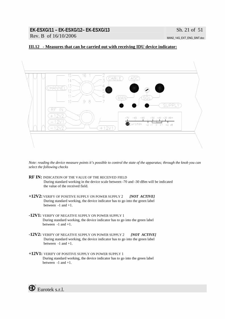
III.12 - Measures that can be carried out with receiving IDU device indicator:
Note: reading the device measure points it’s possible to control the state of the apparatus; through the knob you can select the following checks RF IN: INDICATION OF THE VALUE OF THE RECEIVED FIELD During standard working in the device scale between -70 and -30 dBm will be indicated the value of the received field.
+12V2: VERIFY OF POSITIVE SUPPLY ON POWER SUPPLY 2 [NOT ACTIVE] During standard working, the device indicator has to go into the green label between -1 and +1. -12V1: VERIFY OF NEGATIVE SUPPLY ON POWER SUPPLY 1 During standard working, the device indicator has to go into the green label between -1 and +1. -12V2: VERIFY OF NEGATIVE SUPPLY ON POWER SUPPLY 2 [NOT ACTIVE] During standard working, the device indicator has to go into the green label between -1 and +1. +12V1: VERIFY OF POSITIVE SUPPLY ON POWER SUPPLY 1
During standard working, the device indicator has to go into the green label between -1 and +1.

EK-ESXG/11 – EK-ESXG/12– EK-ESXG/13 Rev. B of 16/10/2006
Sh. 22 of 51
MAN2_14G_EXT_ENG_SINT.doc
Eurotek s.r.l.
III.13 - Position diagram of jumpers on the receiving IDU:

EK-ESXG/11 – EK-ESXG/12– EK-ESXG/13 Rev. B of 16/10/2006
Sh. 23 of 51
MAN2_14G_EXT_ENG_SINT.doc
Eurotek s.r.l.
III.14 - Internal lay-out of receiving IDU:
Note: remove the cover to change the jumpers position.

EK-ESXG/11 – EK-ESXG/12– EK-ESXG/13 Rev. B of 16/10/2006
Sh. 24 of 51
MAN2_14G_EXT_ENG_SINT.doc
Eurotek s.r.l.
III.15 - Rear description suitable for receiving and transmitting ODU:
A) ODU¹ support handle B) Link connector to measurement unit EK-TMS/1
C) Link connector to IDU(receiver or transmitter)
1 – Waveguide orientation in output (when it is present), is parallel to the handle “A”; so pay attention, during the installation, that the handles of two ODU, either the receiving or the transmitting, are oriented in the same way. This in case that the Units are linked to antenna’s systems with direct connection to feed in round waveguide.
Please always close with special plug the “B”connector,
when not in use

EK-ESXG/11 – EK-ESXG/12– EK-ESXG/13 Rev. B of 16/10/2006
Sh. 25 of 51
MAN2_14G_EXT_ENG_SINT.doc
Eurotek s.r.l.
III.16 - Measurement unit EK-TMS/1 description:
A) red LED indicating:
• in the receiving ODU, the system in squelch • in the transmitting ODU, the alarm relative to a power loss
B) green LED indicating the presence of ODU power supply C) Link connector to ODU (see letter B page 24) D) Device indicating:
• in the receiving ODU, the received field intensity • in the transmitting ODU, the transmitted power
DEVICE READING (D) Rx FUNCTION TX FUNCTION
READ VALUE dBm READ VALUE POWER OUT 9 -40 9 ÷ 10 Nominal Power 8 -50 7 ÷ 8 -2 dB 6 -60 5 ÷ 6 -3 dB 4 -70 1 -80 0 -90

EK-ESXG/11 – EK-ESXG/12– EK-ESXG/13 Rev. B of 16/10/2006
Sh. 26 of 51
MAN2_14G_EXT_ENG_SINT.doc
Eurotek s.r.l.
IV - MOUNTING INSTRUCTIONS
IV.1 - ODU assembling and supply configuration:
The ODU assembling and supply configuration are the following: 1) Mobile post assembling (only for EK-ES10G/11)
2) Resident post assembling (on pole) with 335 or 600mm parabolic reflector (only for EK-ES10G/11)
3) Resident post assembling (on pole) with arrangement to the flexible waveguide link only

EK-ESXG/11 – EK-ESXG/12– EK-ESXG/13 Rev. B of 16/10/2006
Sh. 27 of 51
MAN2_14G_EXT_ENG_SINT.doc
Eurotek s.r.l.
IV.2 - ODU assembling configuration in mobile post:
Side view:

EK-ESXG/11 – EK-ESXG/12– EK-ESXG/13 Rev. B of 16/10/2006
Sh. 28 of 51
MAN2_14G_EXT_ENG_SINT.doc
Eurotek s.r.l.
Rear view (fully assembled):

EK-ESXG/11 – EK-ESXG/12– EK-ESXG/13 Rev. B of 16/10/2006
Sh. 29 of 51
MAN2_14G_EXT_ENG_SINT.doc
Eurotek s.r.l.
LEGEND Fig. on page 27-28
A Parabolic reflector B Circle for parabolic reflector support
C-D Knobs for high-azimuth orientation E Ring for parabolic reflector support F Spring toggle latch
G-H Knobs for latitude orientation I Fastening pivot on tripod N L OutDoor Unit (ODU) M Fastening eyebolt to the pivot L N Complete ODU support tripod O Fastening hook on ODU
Parabolic reflector assembling shall be carry out as follows: 1) The overall of parabolic reflector (see fig. page 27) is supplied already assembled and complete in every its own parts
(from the letter A to the letter I); 2) Subsequently, shall be arranged the ODU (L), to the parabolic reflector (A), hooking the four bolts (F) to the four
hooks (O) on the ODU, as shown in the figure on page 27. 3) Now, the overall has to be fasten to the support tripod (N), putting the fastening pivot (I) in the special hole into the
base of the tripod as shown in fig. on page 27, and finishing to assemble putting the eyebolt (M) screwing down it on the pivot itself, as shown in the figures on page 27 and 28.
To secure a greater stability to the overall so achieved, it is advisable to hang a weight (30Kg max.) at the eyebolt (M).
VERY IMPORTANT! The polarization of the radiated and received electric field, is right-angled to the handle “H”; so pay attention that the handles of two units, the receiving one and the transmitting one, are
oriented in the same way.

EK-ESXG/11 – EK-ESXG/12– EK-ESXG/13 Rev. B of 16/10/2006
Sh. 30 of 51
MAN2_14G_EXT_ENG_SINT.doc
Eurotek s.r.l.
IV.3 - ODU in resident post assembling configuration with parabolic reflector:
The parabolic reflector is supplied already assembled and complete with every parts indicated in the picture here below

EK-ESXG/11 – EK-ESXG/12– EK-ESXG/13 Rev. B of 16/10/2006
Sh. 31 of 51
MAN2_14G_EXT_ENG_SINT.doc
Eurotek s.r.l.

EK-ESXG/11 – EK-ESXG/12– EK-ESXG/13 Rev. B of 16/10/2006
Sh. 32 of 51
MAN2_14G_EXT_ENG_SINT.doc
Eurotek s.r.l.
LEGEND Fig. page 30-31
A Parabolic reflector B Support plate of parabolic reflector C High-azimuth orientation D Latitude orientation E Spring toggle latch F Protection plate G Outdoor Unit (ODU) H ODU support handle I Fixing “U” bar L Support pole M Fastening hook on ODU
To assembling the parabolic reflector, please proceed as follows: 1) The overall of the parabolic reflector (A fig. page 30) together with the support plate (B fig. page 30), has to be
fastened to the support pole (L fig. page 31) by the two “U” bars (I fig. page 30), with relative nuts and washers (flat + grower) ø10, as shown in fig. on page 31;
2) Subsequently, has to be arranged the protection plate (F fig. page 31), by relative nuts and bolts M10x30 included in the supply, as shown as ever in fig. on page 31;
3) Now, we proceed linking the ODU (G fig. page 31) to the parabolic reflector (A), hooking the four latches (E fig. page 30) to the four hooks on the ODU (M), as shown in fig. on page 31.

EK-ESXG/11 – EK-ESXG/12– EK-ESXG/13 Rev. B of 16/10/2006
Sh. 33 of 51
MAN2_14G_EXT_ENG_SINT.doc
Eurotek s.r.l.
IV.4 - ODU in resident post assembling configuration without parabolic reflector:
The resident post without parabolic reflector is composed of the parts represented here below;

EK-ESXG/11 – EK-ESXG/12– EK-ESXG/13 Rev. B of 16/10/2006
Sh. 34 of 51
MAN2_14G_EXT_ENG_SINT.doc
Eurotek s.r.l.

EK-ESXG/11 – EK-ESXG/12– EK-ESXG/13 Rev. B of 16/10/2006
Sh. 35 of 51
MAN2_14G_EXT_ENG_SINT.doc
Eurotek s.r.l.
LEGEND Fig. page 33-34
B1,B2 Bolt M10 x 25 BA1,BA2 “U” bar ø10mm with threaded M10 extremities
D1,D2,D3,D4,D5,D6 Nut M10 D7,D8,D9,D10 Nut M6 G1,G2,G3,G4 Stud M6x30mm for fastening to plate “P”
O OutDoor Unit (ODU) P ODU support plate
PA Support pole RG1,RG2,RG3,RG4,RG5,RG6 Grower washer ø10
RG7,RG8,RG9,RG10 Grower washer ø6 RP1,RP2,RP3,RP4,RP5,RP6 Flat washer ø10
RP7,RP8,RP9,RP10 Flat washer ø6 T Roof for ODU support plate
The post assembling shall be done as follows: Please join the cover plate (T) for the ODU to the support plate (P) by the nuts, the washers (flat and grower) and bolts ø10, fitting the holes on to the plates. (see fig. page 34). Then, please fasten the overall composed by the plates (P)+(T) to the support pole (PA) by the “U” bars (BA1&BA2) and relative four nuts and washers (flat and grower) ø10. (see fig. page 34). Now, we have to fasten the ODU (O) to the support plate (P) fitting the four studs (G1÷G4) with the special holes by the four nuts and washers (flat and grower) ø6. By the position of the holes on the support plate (P), it’s possible to put the ODU (O) either in horizontal position or in vertical position.

EK-ESXG/11 – EK-ESXG/12– EK-ESXG/13 Rev. B of 16/10/2006
Sh. 36 of 51
MAN2_14G_EXT_ENG_SINT.doc
Eurotek s.r.l.
IV.5 - Pointing procedure of parabolic reflector in mobile post configuration:
About the pointing of parabolic reflector, please proceed as follows: 1) The high-azimuth orientation (high-low), can be carried out in this way:
• placed ourselves behind the parabolic reflector, please rotate at the same time the knob D (fig. page 27) in anti-clockwise direction and the C one (fig. page 26) in a clockwise direction only, until to reach the end stroke
• at this point, rotate the knob D freely in a clockwise direction or in anti-clockwise direction, until to reach the requested position with the parabolic reflector
• rotate at the same time the knob D in a clockwise direction and the C one in anti-clockwise direction until to clench them strongly to the ring E (fig. page 27)
2) The latitude orientation (right-left), can be carried out in this way:
• placed ourselves behind the parabolic reflector, please rotate at the same time the knob H (fig. page 27 in anti-clockwise direction and the G one (fig. page 27) in a clockwise direction only, until to reach the end stroke
• at this point, rotate the knob H freely in a clockwise direction or in anti-clockwise direction until to reach the requested position with the parabolic reflector
• rotate at the same time the knob H in a clockwise direction and the G one in anti-clockwise direction until to clench them strongly to the ring E (fig. page 27)
IV.6 - Pointing procedure of parabolic reflector in resident post configuration:
About the pointing of parabolic reflector, please proceed as follows: 1) The high-azimuth orientation (high-low), can be carried out acting opportunely on two fastening nuts (C page 30) of
the parabolic reflector (A page 30) to the support plate (B page 30) only; all the others fastening nuts have to be fully clenched.
2) The latitude orientation (right-left), can be carried out acting opportunely on two fastening nuts (D page 30) of the parabolic reflector (A) to the support plate (B) only; all the others fastening nuts have to be fully clenched.
VERY IMPORTANT! To the end of fixing and pointing operations of the parabolic antenna, it’s important to be
sure that all the nuts are fully clenched, to avoid that sudden gusts or any other, can compromise the correct pointing and/or the assembly safety.

EK-ESXG/11 – EK-ESXG/12– EK-ESXG/13 Rev. B of 16/10/2006
Sh. 37 of 51
MAN2_14G_EXT_ENG_SINT.doc
Eurotek s.r.l.
V - WORKING DESCRIPTION
V.1 – IDU-ODU transmitting block diagram:

EK-ESXG/11 – EK-ESXG/12– EK-ESXG/13 Rev. B of 16/10/2006
Sh. 38 of 51
MAN2_14G_EXT_ENG_SINT.doc
Eurotek s.r.l.
V.2 – Transmitting working description (EK-ES2G/13; EK-ES5G/12; EK-ES7G/12):
Video signal in input is filtered to limit its bandwidth to 5,5 MHz and, if opportunely selected, emphasized according to CCIR 405-1 recommendation; a trimmer on the front panel allows to adjust video modulation sensitivity. Then video signal is mixed with sub-carriers of FDM system modulated by audio signals and stabilized in frequency using phase-locked loop circuits; it is possible to set an emphasis at 50 µS. Audio modulation sensitivity is adjustable using a trimmer placed in the front panel. The base-band signal is sent to two amplifiers, an inverting one and a non-inverting one, that drive two oscillators; output signals from oscillators are mixed and filtered to obtain a carrier at 70 MHz modulated by base-band signal. It is also available an auxiliary IF input at 70 MHz that, if its power level is upper than –6dBm, is carried out automatically at IF output port,( we must connect the pin 10 with the pin 1 of the remote connector) replacing modulator output signal; to indicate that auxiliary IF signal is carried out, a yellow led is alight on the front panel. IF signal is amplified and sent to an auxiliary output port; through a 75 Ohm coaxial cable the signal at 70 MHz is sent to ODU to a double conversion synthesized converter; here the signal is mixed and filtered to obtain an intermediate frequency of 1000 MHz (EK-ES2G/13, EK-ES10G/11); 1189 MHz (EK-ES5G/12); 1540 MHz (EK-ES7G/12) and then again mixed with a signal generated by a local oscillator at 3312 ÷ 3687 MHz (EK-ES2G/13), 4076 ÷ 4246 (EK-ES5G/12), 6442 ÷ 7044 MHz (EK-ES7G/12) whose working frequency is set by the channel knob on IDU front panel, to obtain the output frequency band of 2,3 ÷ 2,7 GHz (EK-ES2G/13), 5,2 ÷ 5,5 GHz (EK-ES5G/12), 6,4 ÷ 7 GHz (EK-ES7G/12) now the signal is filtered and sent to the power amplifier. A detector on power amplifier output allows to see output power level on the front panel indicator and a red led is a light when output power is 3 dB lower than the nominal one. The right working of all parts of the transmitter is checked by a microprocessor that keeps in memory channels frequencies and manages the synthesized converter.

EK-ESXG/11 – EK-ESXG/12– EK-ESXG/13 Rev. B of 16/10/2006
Sh. 39 of 51
MAN2_14G_EXT_ENG_SINT.doc
Eurotek s.r.l.
V.3 – IDU-ODU receiving block diagram:

EK-ESXG/11 – EK-ESXG/12– EK-ESXG/13 Rev. B of 16/10/2006
Sh. 40 of 51
MAN2_14G_EXT_ENG_SINT.doc
Eurotek s.r.l.
V.4 - Receiving working description (EK-ES2G/13; EK-ES5G/12; EK-ES7G/12):
The received signal is frequency limited by input filter of the synthesized converter at double conversion; then the signal is firstly mixed with the signal generated by a local oscillator at 3312 ÷ 3687 MHz (EK-ES2G/13), 4076 ÷ 4246 MHz (EK-ES5G/12), 6442 ÷ 7044 MHz (EK-ES7G/12), whose working frequency is set by the channel knob on IDU front panel, to obtain the intermediate frequency of 1000 MHz (EK-ES2G/13, EK-ES10G/11); 1189 MHz (EK-ES5G/12); 1540 MHz (EK-ES7G/12). The signal is filtered and mixed with the signal generated by a local oscillator at 1070 MHz (EK-ES2G/13, EK-ES10G/11); 1119 MHz (EK-ES5G/12); 1470 MHz (EK-ES7G/12), to obtain the output IF signal at 70 MHz. Using a SAW filter (Surface Acoustic Wave) is marked the selectivity of the radio link; there are also equalization cells for group delay due to filters. The amplification chain with variable gain compensates the fluctuation of RF attenuation and keeps at the nominal power level the IF output one. IF signal is amplitude limited before to arrive to the discriminator; from its output the base-band signal is sent to an amplifier, to a de-emphasizer and filtered to eliminate the FDM audio part. The audio sub-carriers are filtered and then demodulated to be available at their output ports.

EK-ESXG/11 – EK-ESXG/12– EK-ESXG/13 Rev. B of 16/10/2006
Sh. 41 of 51
MAN2_14G_EXT_ENG_SINT.doc
Eurotek s.r.l.
V.5 – IDU-ODU transmitting block diagram:

EK-ESXG/11 – EK-ESXG/12– EK-ESXG/13 Rev. B of 16/10/2006
Sh. 42 of 51
MAN2_14G_EXT_ENG_SINT.doc
Eurotek s.r.l.
V.6 – Transmitting working description (EK-ES10G/11, EK-ES12G/11, EK-ES13G/11 EK-ES14G/11,):
Video signal in input is filtered to limt its bandwidth to 5,5 MHz and, if opportunely selected, emphasized according to CCIR 405-1 recommendation; a trimmer on the front panel allows to adjust video modulation sensivity. Then video signal is mixed with sub-carrier of FDM system modulated by audio signals and stabilized in frequency using phase-locked loop circuits; it is possible to set an emphasis at 50 µs. Audio modulation sensivity is adjustable using a trimmer placed in the front panel. The base-band signal is sent to two amplifiers, an inverting one and a non-inverting one, that drive two oscillators; output signals from oscillators are mixed and filtered to obtain a carrier at 70 MHz modulated by base-band signal. It is also available an auxiliary IF input at 70 MHz that, if its power level is upper than –6 dBm, is carried out automatically at IF output port, ,( we must connect the pin 10 with the pin 1 of the remote connector) replacing modulator output signal; to indicate that auxiliary IF signal is carried out, a yellow led is alight on the front panel. IF signal is amplified and sent to an auxiliary output port; through a 75 Ohm coaxial cable the signal at 70 MHz is sent to ODU to a triple conversion synthesized converter; here the signal is mixed and filtered to obtain an intermediate frequency of 1 GHz and then again mixed with a signal generated by a local oscillator at 3,3 ÷ 3,7 GHz, whose working frequency is set by the channel knob on IDU front panel, to obtain the output frequency band of 2,3 ÷ 2,7 GHz, this signal is again mixed with a signal generated by a fixed local oscillator at 13 GHz to obtain the output frequency band of 10,3 ÷ 10,7 GHz; now the signal is sent to the power amplifier and filtered. A detector on power amplifier output allows to monitor output power level on the front panel indicator and a red led is light when output power is 3 dB lower than the nominal one. The right working of all parts of the transmitter is checked by a microprocessor that keep in memory channels frequencies and manages the synthesized converter.

EK-ESXG/11 – EK-ESXG/12– EK-ESXG/13 Rev. B of 16/10/2006
Sh. 43 of 51
MAN2_14G_EXT_ENG_SINT.doc
Eurotek s.r.l.
V.7 – IDU-ODU receiving block diagram:

EK-ESXG/11 – EK-ESXG/12– EK-ESXG/13 Rev. B of 16/10/2006
Sh. 44 of 51
MAN2_14G_EXT_ENG_SINT.doc
Eurotek s.r.l.
V.8 – Receiving working description (EK-ES10G/11, EK-ES12G/11, EK-ES13G/11 EK-ES14G/11,):
The received signal is frequency limited by a six cavity filter; then the signal is firstly low-noise preamplified and subsequently again filtered by a two cavity filter to delete the noise that is present on the image-frequency. Now the signal is mixed by a local oscillator at 13 GHz, to obtain the frequency band at 2,3 ÷ 2,7 GHz, and sent to a synthesized converter. Here the signal is firstly mixed by a local synthesized oscillator at 3,3 ÷ 3,7 GHz to obtain the intermediate frequency of 1 GHz. The signal at 1 GHz is filtered and mixed with the signal generated by a local oscillator at 1,070 GHz to obtain the output IF signal at 70 MHz. Using a SAW filter (Surface Acoustic Wave) is marked the selectivity of the radio link; there are also equalization cells for group delay due to filters. The amplification chain with variable gain compensates the fluctuation of RF attenuation and keeps at the nominal power level the IF output one. IF signal is amplitude limited before to arrive to the discriminator; from its output the base-band signal is sent to an amplifier, to a de-emphasizer and filtered to eliminate the FDM audio part. The audio sub-carriers are filtered and then demodulated to be available at their output ports.

EK-ESXG/11 – EK-ESXG/12– EK-ESXG/13 Rev. B of 16/10/2006
Sh. 45 of 51
MAN2_14G_EXT_ENG_SINT.doc
Eurotek s.r.l.
VI - INSTALLATION ARRANGEMENTS
VI.1 – Thermal dissipation:
To favour thermal exchange between IDU part and environment, it is necessary to place each unit spacing out it as far as a rack 1U height both above and under it, always placing the apparatus horizontally.
VI.2 – Pins of telecontrol connector:
Pin Tx function Rx function Contact type 1 GND GND GND 2 Manual N.A. 3 IF2 N.A. 4 Not connected Not connected Not connected 5 Mod. unlock N.A. 6 Not connected Not connected Not connected 7 Audio all. Audio all. N.C. 8 Pwr out Squelch N.C. 9 Pwr supply Pwr supply N.A. 10 IF2 Not connected Command O.C. 11 Relais common Relais common Relais common 12 + 12 V2 + 12 V2 + 12 V2 13 - 12 V2 - 12 V2 - 12 V2 14 GND GND GND 15 Manual N.C. 16 IF2 N.C. 17 Not connected Not connected Not connected 18 Mod. unlock N.C. 19 Audio all. Audio all. N.A. 20 Pwr out Squelch N.A. 21 Power indication Field indication See graph.pag 46 22 + 12 V1 + 12 V1 + 12 V1 23 Not connected Not connected 24 Relais common Relais common Relais common 25 - 12 V1 - 12 V1 - 12 V1
N.A. = normally open contact
N.C. = normally closed contact
O.C. = active open collector closed on ground

EK-ESXG/11 – EK-ESXG/12– EK-ESXG/13 Rev. B of 16/10/2006
Sh. 46 of 51
MAN2_14G_EXT_ENG_SINT.doc
Eurotek s.r.l.
Graph concerning the trend of voltage on pin 21 of telecontrol connector in relation to transmitter power field
0123456
30 29 28 27 26 25 24 23 22 21 20 19 18 17 16
Transmitted power level (dBm)
Mea
sure
d vo
ltage
Graph concerning the trend of voltage on pin 21 of telecontrol connector in relation to received field
0
1
2
3
4
5
6
7
8
-35 -40 -45 -50 -55 -60 -65 -70
Received field dBm
Mea
sure
d vo
ltage

EK-ESXG/11 – EK-ESXG/12– EK-ESXG/13 Rev. B of 16/10/2006
Sh. 47 of 51
MAN2_14G_EXT_ENG_SINT.doc
Eurotek s.r.l.
VI.3 – ODU IDU CONNECTION
VERY IMPORTANT! In place where high emissions of low frequencies signal are present(ex. FM), he is advisable
to use a cable type CELLFLEX in order to connect ODU and IDU
VII - CANALIZATION
VII.1 - EK-ES2G/13
CHANNEL RF OL 1 OL 2 1 2312 1070 3312 2 2337 1070 3337 3 2362 1070 3362 4 2387 1070 3387 5 2412 1070 3412 6 2437 1070 3437 7 2462 1070 3462 8 2487 1070 3487 9 2512 1070 3512 10 2537 1070 3537 11 2562 1070 3562 12 2587 1070 3587 13 2612 1070 3612 14 2637 1070 3637 15 2662 1070 3662 16 2687 1070 3687
VII.2 - EK-ES5G/12
CHANNEL RF OL 1 OL 2 1 5265 1119 4076 2 5293 1119 4104 3 5321 1119 4132 4 5379 1119 4190 5 5407 1119 4288 6 5435 1119 4246

EK-ESXG/11 – EK-ESXG/12– EK-ESXG/13 Rev. B of 16/10/2006
Sh. 48 of 51
MAN2_14G_EXT_ENG_SINT.doc
Eurotek s.r.l.
VII.3 - EK-ES7G/12
TYPE of BAND CHANNEL RF OL 1 OL 2 1 6442 1470 4972 2 6484 1470 5014 3 6526 1470 5056 4 6568 1470 5098 5 6610 1470 5140 6 6652 1470 5182 7 6694 1470 5524
LOW BAND
8 6736 1470 5266 9 6778 1470 5308 10 6820 1470 5350 11 6862 1470 5392 12 6904 1470 5434 13 6946 1470 5476 14 6988 1470 5518 15 7030 1470 5490
HIGH BAND
16 7072 1470 5532
VII.4 -EK-ES10G/11
CHANNEL RF OL 1 OL 2 OL 3 1 10310 1070 3690 13000 2 10330 1070 3670 13000 3 10350 1070 3650 13000 4 10370 1070 3630 13000 5 10390 1070 3610 13000 6 10410 1070 3590 13000 7 10430 1070 3570 13000 8 10450 1070 3550 13000 9 10520 1070 3480 13000 10 10540 1070 3460 13000 11 10560 1070 3440 13000 12 10580 1070 3420 13000 13 10600 1070 3400 13000 14 10620 1070 3380 13000 15 10640 1070 3360 13000 16 10660 1070 3340 13000

EK-ESXG/11 – EK-ESXG/12– EK-ESXG/13 Rev. B of 16/10/2006
Sh. 49 of 51
MAN2_14G_EXT_ENG_SINT.doc
Eurotek s.r.l.
VII.5 -EK-ES12G/11
CHANNEL RF OL 1 OL 2 OL 3 1 11112 1070 3648 13760 2 11128 1070 3632 13760
3 11148 1070 3612 13760
4 11168 1070 3592 13760
5 11188 1070 3572 13760
6 11208 1070 3552 13760
7 11228 1070 3532 13760
8 11248 1070 3512 13760
9 11268 1070 3492 13760
10 11288 1070 3472 13760
11 11308 1070 3452 13760
12 11328 1070 3432 13760
13 11348 1070 3412 13760
14 11368 1070 3392 13760
15 11388 1070 3372 13760
16 11408 1070 3352 13760
VII.6 -EK-ES14G/11
CHANNEL RF OL 1 OL 2 OL 3 1 14260 1070 3385 11875 2 14280 1070 3405 11875
3 14300 1070 3425 11875
4 14320 1070 3445 11875
5 14340 1070 3465 11875
6 14360 1070 3485 11875
7 14390 1070 3515 11875
8 14410 1070 3535 11875
9 14430 1070 3555 11875
10 14450 1070 3575 11875
11 14470 1070 3595 11875
12 14490 1070 3615 11875
13 14260 1070 3385 11875 14 14280 1070 3405 11875
15 14300 1070 3425 11875
16 14320 1070 3445 11875

EK-ESXG/11 – EK-ESXG/12– EK-ESXG/13 Rev. B of 16/10/2006
Sh. 50 of 51
MAN2_14G_EXT_ENG_SINT.doc
Eurotek s.r.l.
VII.7 -EK-ES13G/11
Canalizations not available. Please contact EUROTEK offices.

EK-ESXG/11 – EK-ESXG/12– EK-ESXG/13 Rev. B of 16/10/2006
Sh. 51 of 51
MAN2_14G_EXT_ENG_SINT.doc
Eurotek s.r.l.
Eurotek S.r.l. c/o Parco Scientifico Tecnologico e delle
Telecomunicazioni in Valla Scrivia Strada Comunale Savonesa, 9
15050 RIVALTA SCRIVIA (AL) tel. +39 0131860205 fax +39 0131860993
http://www.eurotektel.com e-mail: [email protected]