user's guide: ri-network diode one-way transfer device
TRANSCRIPT

www.rumel-online.com
User's Guide:RI-Network DiodeOne-Way TransferDevice
rumeL, Inc.www.rumel-online.com540-338-3252
May 2008For Software Version 1.00
Prepared by: rumeL, Inc10302 Eaton Place Suite 240
Fairfax, Virginia 22030www.rumel-online.com
Bill OwenPresident
rumeL, Inc. Page 1 of 48

www.rumel-online.com
Table of Contents1.0 Summary and Scope.....................................................................................................32.0 rumeL, Inc. Network Diode Quickstart Guide..............................................................33.0 One Way Transfer Diode Introduction.........................................................................5
3.1 Operation..................................................................................................................53.2 Configuration...........................................................................................................73.3 Programming............................................................................................................7
4.0 Software........................................................................................................................84.1 Build Scripts and the txdiode and rxdiode Executables...........................................84.2 The rxdiode and txdiode Executables....................................................................10
5.0 Commands..................................................................................................................125.1 Rx & Tx Hardware program and prgclrcfg Commands.........................................135.2 Rx Hardware flashcfg Command..........................................................................165.3 Rx Hardware Configuration File Parameter Description.......................................185.4 Tx Hardware flashcfg Command...........................................................................205.5 Tx Hardware Configuration File Parameter Description.......................................235.6 Rx & Tx Hardware query and qrywcfg Commands..............................................255.7 Rx Hardware transmitfile, and Tx Hardware receivefile Commands....................285.8 Tx Hardware acquire, acqwtc, and acqall Commands...........................................30
6.0 Communications.........................................................................................................336.1 “Catch-22”..............................................................................................................346.2 Maximizing Tx Hardware to Host Computer Data Transfer Rates ......................356.3 Determining Hardware/Mac Addresses ................................................................36
7.0 Address Removal and Re-Mapping............................................................................388.0 Network Diode File Transfer......................................................................................409.0 Security.......................................................................................................................4510.0 rumeL, Inc. Network Diode Pictures........................................................................46
rumeL, Inc. Page 2 of 48

www.rumel-online.com
1.0 Summary and Scope The application of one way transfer devices are typically in the transfer of
data from “low” side (unclassified) networks to “high” side (classified) networks.In subsequent sections, the operations for rumeL, Inc's RI-Network Diode, anetwork one way transfer device will be discussed. The design for the RI-Network Diode provides for full Gigabit Ethernet data transfer rates in a oneway network direction. In other words, the Network Diode internally,operates at much faster rates than Gigabit Ethernet standards andtherefore create a data transfer “bottlenecks”.
2.0 rumeL, Inc. Network Diode Quickstart Guide1.) The most up-to-date software can be obtained at:http://www.rumel-online.com/software.htm(Note extension is .htm NOT .html)
2). Attach power supplies and network cables for Rx and Tx hardwarecommunications. (The Network Diode may be connected directly to the hostmachine or to a router network where the host machine resides.)
3) Copy the Rx Hardware software rxdiodevA_BC.zip and the Tx hardwaresoftware txdiodevA_BC.zip to there respective hosts.
4).The Rx hardware IP address when delivered is 192.9.200.115. The Txhardware IP address when delivered is 192.9.200.116. See the section titledCommunications for information on how to set the host computer route toidentify the address of 192.9.200.115 and 192.9.200.116
5) On the Rx software Host computer execute: ping 192.9.200.115 <return> tobe sure communications are established with the Rx hardware. On the Txsoftware Host computer execute: ping 192.9.200.116 <return> to be surecommunication are established with the Tx hardware.
6) Refer to the section: Build Scripts and the txdiode and rxdiodeExecutables in the User Guide on how unzip/build the rxdiode and txdiodeexecutables.
7) Refer to the section: Commands for generic help on the commands.
8) Refer to the section: Rx Hardware flashcfg Command , and Rx HardwareConfiguration File Parameter Description on how to configure the Rxhardware for your applications.
rumeL, Inc. Page 3 of 48

www.rumel-online.com
9) Refer to the section: Tx Hardware flashcfg Command , and Tx HardwareConfiguration File Parameter Description on how to configure the Txhardware for your applications.
10) Execute the flashcfg command to configure the Rx hardware with a new IPaddress and configuration parameters.11) Execute the flashcfg command to configure the Tx hardware with a new IPaddress and configuration parameters.
12) Refer to the section: query And qrywcfg Commands on how to verifyconfiguration settings for steps 10 &11.
13) Refer to the section Network Diode File Transfer on how to transfer filesacross the Network Diode.
14) Refer to the section: acquire, acqall, and acqwtc Commands on how toacquire data to the Host computer that is in SDDS format (generated by a rumeL,Inc. GIGEXD product).
15) Refer to section: "Catch-22" for information on setting the Rx or Tx hardwareback to its factory default settings.(Important)
Other points:A. The Rx and Tx hardware of the Network Diode should only be connecteddirectly to Gigabit Ethernet interfaces. They will NOT communicatewith100Base-T or 10Base-T interfaces.B. Firmware & Software updates will be posted on the web when new featuresare added. Some of the new features to be added are detailed in the NetworkDiode User Guide.C. Finally, any questions can be directed to:
Bill OwenrumeL, [email protected]
Applicable Documents1. V. Anantharam, and S.Verdu, “Bits through queues,” Information Theory, IEEETransactions on , Volume: 42 , Issue: 1 , Jan. 1996.
2. V. Anantharam and S. Verdú, ``Reflections on the 1998 Information Theory SocietyPaper Award: Bits through Queues,'' IEEE Information Theory Society Newsletter vol.49, no. 4, Dec. 1999.
3. J. S. Holmgren and R. P. Rich, Metric Methodology for the Creation of Environmentsand Processes to Certif Component: The NRL Pump, Naval Postgraduate SchoolMonterey CA, March 2003.
rumeL, Inc. Page 4 of 48

www.rumel-online.com
3.0 One Way Transfer Diode Introduction
The diagrams above show conceptually the use of the One Way Transfer Diode.In implementation, the One Way transfer Diode has 2 sections of hardware. The receive(Rx), or input, hardware section is shown on left side of Figure 2. The Rx hardwarecan be programmed, configured, and accepts data for transfer to the fiber diode interface.Once at the fiber diode interface data is transported to the transmit (TX) interface (rightside of Figure 2). From the Tx interface data is sent out to host IP addresses previouslyconfigured in the Tx interface hardware.
3.1 OperationAs mentioned above the Network Diode is comprised of two pieces of hardware
connected by a single fiber optic link. The Rx piece of hardware contains a Primary IPaddress and up to 4 Target IP addresses. The Primary IP address is used to configure or
rumeL, Inc. Page 5 of 48
Low SideNetwork Low
SendingComputer
High SideNetworkHigh
ReceivingComputer
One WayTransfer“Diode”
One Way Network TransferUsing One Way Transfer Diode
Figure 1 – High Level One Way Transfer Diode
Data OnlyTransfer
DataLow SideConfig &AcknowlegeCircuitry
Cfg
Ack
High SideConfig &AcknowlegeCircuitry
Data Data
Cfg
Ack
Data
“True” DiodeCircuitry
Figure 2 – Overview Of Diode Circuitry

www.rumel-online.com
program the Rx side of the Diode over its Gigabit Ethernet Interface. The 4 Target IPaddresses are set by the user via the same Gigabit Ethernet interface during configurationcommands to the Primary IP address. These Target IP addresses may be any valid IPaddress, including the Multicast group of addresses. These 4 Target IP addresses arelistening addresses. Any UDP protocol packet that corresponds as being sent to theseaddresses will be forward across that fiber link to the Tx hardware interface.(See Fig. 3)
Like the Rx circuitry, the Tx circuitry has a Primary IP address that is used forprogramming and configuration. Along with the Primary IP address, up to 4 Target IPaddresses can be configured with the Tx section of hardware. These 4 Target IPaddresses serve as the target IP addresses where data is to be sent once it is receivedacross the fiber interface from the Rx section of hardware. All valid IP addresses areallowed including those in the Multicast address range. (See Figure 3)
Data transfers are shown and discussed in this document from low side to highside but use of the Network Diode in the opposite direction, high side to low side, is alsopossible. rumeL, Inc. 1U rack mount units can be configured with 2 Network Diodes toprovide for the ability to go both directions.
rumeL, Inc. Page 6 of 48
Fiber OpticLaser
Tx Only
Fiber OpticLaser
Rx OnlyTx Rx Tx Rx
Fiber Opticor
Copper RJ-45
Fiber Opticor
Copper RJ-45
Low Side Network Connect
Rx
High Side Network Connect
Tx
Single Fiber Cable
Low SidePCB
High SidePCB
High SidePower Connect
Low SidePower Connect
Low Side Circuitry-Error Checking-Configuration-Low Side Network Coms
High Side Circuitry-Error Checking-Configuration-High Side Network Coms-Address Re-Mapping
“True” Diode Circuitry3 Uses:1.) Rx Programming2.) Rx Configuration3.) Rx Data Input
3 Uses:1.) Tx Programming2.) Tx Configuration3.) Tx Data Output
Figure 3 – Detail Of Diode Circuitry

www.rumel-online.com
3.2 ConfigurationAs briefly stated in section 3.1 the Diode configuration is a two step process that
is accomplished over the Rx and Tx hardware Gigabit Ethernet ports. The Rx section ofhardware, is configured with 4 IP addresses that it listens to for receipt of UDP packets.The listening IP addresses are numbered 1 through 4 in the configuration section of theRx hardware. These 4 listening addresses correspond to 4 target addresses configured inthe Tx section of hardware. The mapping is simply a 1:1 correspondence. Data receivedfor listening IP address 1 will be forwarded to the Tx section of hardware and then sentout to target IP address 1. Data received for listening IP address 2 will be forwarded tothe Tx section of hardware and then sent out to target IP address 2—and so on.
For both the Rx (Low Side) and Tx (High Side) IP addresses configuration isdone over the Rx or Tx Gigabit Ethernet port, respectively, via a C program. The Cprogram takes input from a text configuration file that is setup by the user. Once read,the data from the configuration file is sent to the Rx or Tx section's flash memory fornon-volatile storage. The non-volatile storage means that all configuration is retainedthrough power cycles-whether the power cycles are intentional or not. Along with theTarget IP addresses in both the Rx and Tx hardware, the Primary IP addresses of both theRx and Tx hardware are configurable. Upon delivery the Rx hardware has the Primary IPaddress of 192.9.200.115. The Tx hardware has the default IP address of 192.9.200.116.
Once configured the Rx or Tx hardware will run in its programmed mode untilre-configured again. This allows for lower configuration cycles and maintenance. Seethe description of the rxdiode.c and txdiode.c programs and the rxdiodeusr.cfg andtxdiodeusr.cfg configuration files below for more details on hardware configuration.
Finally, on both the Rx and Tx hardware is a "default button". This button whenpressed and held for 2 seconds will return the Rx and/or Tx hardware to its factorydefault IP addresses. This allows the user to return a Rx or Tx hardware to a default IPaddress for updating configuration or programming.
3.3 ProgrammingThe Rx and Tx hardware contain on-board FPGAs, clock synthesizers, and flash
memories. As updates to the programming of these devices are made available (via therumeL, Inc. web site or ICE software tree downloads), the Rx and Tx hardware can be"re-programmed" to take advantage of these updates over any network. In other words,the Rx and Tx hardware receives their programming over the Gigabit Ethernet interface.As new updates become available, updating the Rx and Tx hardware is simply a matter ofexecuting the C program to reprogram the device with these new features.
rumeL, Inc. Page 7 of 48

www.rumel-online.com
4.0 SoftwareTwo C programs are used to program the Rx and Tx hardware via a host
computer's network port. A Linux build script is included with the software. Currently,the Rx and Tx hardware software zip packages rxdiodevA_BC.zip and txdiodevA_BC.zip,(Where A and BC represent the major and minor version numbers of the associated Rxand Tx software packages) reside on the rumeL, Inc. web site at:http://www.rumel-online.com/software.htm(Note that the above extension is .htm NOT .html)
It is VERY important that versions of Rx and Tx hardware are thesame. As an example, users should NOT use Rx software version 1.01 onthe low side and at the same time be using Tx software version 1.02 on thehigh side. Instead, both Rx and Tx software versions should either bothbe 1.01 or 1.02. Rx software and Tx software versions should be the samefor compatibility during data transfer across the Network Diode. ProblemsWILL arise if this rule is not followed.
4.1 Build Scripts and the txdiode and rxdiode ExecutablesThe software and firmware for the Rx and Tx hardware is bundled into
two zip packages of the form rxdiodevA_BC.zip and txdiodevA_BC.zip. Where Aand BC, as detailed above, represent the major and minor version numbers ofthe associated software packages. When unzipped to a host computer, adirectory of rxdiodevA_BC and txdiodevA_BC are created and allsource/firmware files are unzipped into the directory of rxdiodevA_BC andtxdiodevA_BC-this prevents the mixing of old and new software when packagesare unzipped. As an example, version 1.00 of the Rx and Tx software would bebundled as the zip packages rxdiodev1_00.zip and txdiodev1_00.zip. Extractionof these 2 files would yield the directories of rxdiodev1_00 and txdiodev1_00 withthe associated software files in each of the directories.
rumeL, Inc. Page 8 of 48
www.rumel-online.com
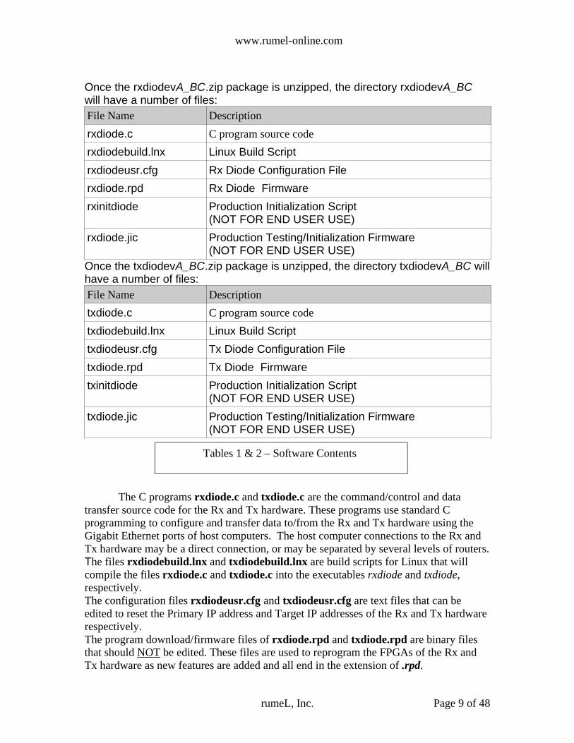
Once the rxdiodevA_BC.zip package is unzipped, the directory rxdiodevA_BCwill have a number of files:File Name Descriptionrxdiode.c C program source coderxdiodebuild.lnx Linux Build Scriptrxdiodeusr.cfg Rx Diode Configuration Filerxdiode.rpd Rx Diode Firmware rxinitdiode Production Initialization Script
(NOT FOR END USER USE)rxdiode.jic Production Testing/Initialization Firmware
(NOT FOR END USER USE)Once the txdiodevA_BC.zip package is unzipped, the directory txdiodevA_BC willhave a number of files:File Name Descriptiontxdiode.c C program source codetxdiodebuild.lnx Linux Build Scripttxdiodeusr.cfg Tx Diode Configuration Filetxdiode.rpd Tx Diode Firmware txinitdiode Production Initialization Script
(NOT FOR END USER USE)txdiode.jic Production Testing/Initialization Firmware
(NOT FOR END USER USE)
The C programs rxdiode.c and txdiode.c are the command/control and datatransfer source code for the Rx and Tx hardware. These programs use standard Cprogramming to configure and transfer data to/from the Rx and Tx hardware using theGigabit Ethernet ports of host computers. The host computer connections to the Rx andTx hardware may be a direct connection, or may be separated by several levels of routers.The files rxdiodebuild.lnx and txdiodebuild.lnx are build scripts for Linux that willcompile the files rxdiode.c and txdiode.c into the executables rxdiode and txdiode,respectively.The configuration files rxdiodeusr.cfg and txdiodeusr.cfg are text files that can beedited to reset the Primary IP address and Target IP addresses of the Rx and Tx hardwarerespectively. The program download/firmware files of rxdiode.rpd and txdiode.rpd are binary filesthat should NOT be edited. These files are used to reprogram the FPGAs of the Rx andTx hardware as new features are added and all end in the extension of .rpd.
rumeL, Inc. Page 9 of 48
Tables 1 & 2 – Software Contents

www.rumel-online.com
rxinitdiode, txinitdiode, rxdiode.jic and txdiode.jic – Production testing andprogramming files. DO NOT ATTEMPT to use these files.The C programs rxdiode.c and txdiode.c provides the user with three tools.1) Ability to reprogram the Rx and Tx firmware with new updates.2) Ability to reconfigure the Rx and Tx hardware with new configuration settings fordifferent IP addresses.3) The ability to send and receive data to/from host computers.The rxdiode.c and txdiode.c programs can be built under Linux by using the build scriptin rxdiodebuild.lnx and txdiodebuild.lnx, respectively.ALL terminal line commands listed in this document are performed in thedirectory rxdiodevA_BC or txdiodevA_BC unless otherwise specified.To build the rxdiode.c source into the executable rxdiode type:>>source rxdiodebuild.lnx <return>The source file rxdiode.c is compiled and the executable rxdiode is produced.To build the txdiode.c source into the executable txdiode type:>>source txdiodebuild.lnx <return>The source file txdiode.c is compiled and the executable txdiode is produced.
4.2 The rxdiode and txdiode ExecutablesOnce built the executables rxdiode and txdiode provide several
commands for the user. At the command line type:>> ./rxdiode <return>The program returns a listing of available commands and their syntax:
rumeL, Inc. Page 10 of 48
rxdiodev1_00> ./rxdiodeSyntax:rxdiode <Operation Type> <Host IP Addr> <DIODERx Primary IP> <Path & Filename> <Rx Target Ip> <Redundant>
<Operation Type> = program, prgclrcfg, flashcfg, query, qrywcfg, flags, or transmitfile <Host IP Addr> = Dot Notation Of Host Machine IP Addr, Ex. 192.9.200.110 <DIODERx Primary IP> = Dot Notation Of DIODERx IP Addr, Ex. 192.168.200.1 <path & filename> = Path & Filename Of Program or Config File(OPTIONAL) or Data File(MANDATORY) <DIODERx Target IP> = Target IP Address Of DIODERx To Send Data-OPTIONAL For Transmitfile Operation <Redundant Tx> = Number Of Times To Resend File Data-OPTIONAL For Transmitfile <Block Wait> = Amount Of uSec To Wait Between Block Transfer-OPTIONAL For Transmitfile
Typing: rxdiode <Operation Type> help Will display help for specific commands
www.rumel-online.com
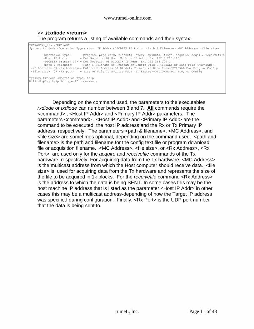
>> ./txdiode <return>The program returns a listing of available commands and their syntax:
Depending on the command used, the parameters to the executablesrxdiode or txdiode can number between 3 and 7. All commands require the<command> , <Host IP Addr> and <Primary IP Addr> parameters. Theparameters <command> , <Host IP Addr> and <Primary IP Addr> are thecommand to be executed, the host IP address and the Rx or Tx Primary IPaddress, respectively. The parameters <path & filename>, <MC Address>, and<file size> are sometimes optional, depending on the command used. <path andfilename> is the path and filename for the config text file or program downloadfile or acquisition filename. <MC Address>, <file size>, or <Rx Address>, <RxPort> are used only for the acquire and receivefile commands of the Txhardware, respectively. For acquiring data from the Tx hardware, <MC Address>is the multicast address from which the Host computer should receive data. <filesize> is used for acquiring data from the Tx hardware and represents the size ofthe file to be acquired in 1k blocks. For the receivefile command <Rx Address>is the address to which the data is being SENT. In some cases this may be thehost machine IP address that is listed as the parameter <Host IP Addr> in othercases this may be a multicast address-depending of how the Target IP addresswas specified during configuration. Finally, <Rx Port> is the UDP port numberthat the data is being sent to.
rumeL, Inc. Page 11 of 48
txdiodev1_00> ./txdiodeSyntax: txdiode <Operation Type> <Host IP Addr> <DIODETX IP Addr> <Path & Filename> <MC Address> <file size>
<Operation Type> = program, prgclrcfg, flashcfg, query, qrywcfg, flags, acquire, acqall, receivefile <Host IP Addr> = Dot Notation Of Host Machine IP Addr, Ex. 192.9.200.110 <DIODETX Primary IP> = Dot Notation Of DIODETX IP Addr, Ex. 192.168.200.1 <path & filename> = Path & Filename Of Program or Config File(OPTIONAL) or Data File(MANDATORY) <MC Address> OR <Rx Address>= Multicast Address Of DiodeTx To Acquire Data From-OPTIONAL For Prog or Config <file size> OR <Rx port> = Size Of File To Acquire Data (In KBytes)-OPTIONAL For Prog or Config
Typing: txdiode <Operation Type> help Will display help for specific commands

www.rumel-online.com
5.0 CommandsFrom the ./rxdiode <return> listing, the available commands are program,
prgclrcfg, flashcfg, query, qrywcfg, flags, or transmitfile. To get syntax specific help on a command type: >> ./rxdiode <Command> help <return>
From the ./txdiode <return> listing, the available commands are program, prgclrcfg,flashcfg, query, qrywcfg, flags, acquire, acqwtc, acqall, receivefile. To get syntax specific help on a command type: >> ./txdiode <Command> help <return>
rumeL, Inc. Page 12 of 48

www.rumel-online.com
5.1 Rx & Tx Hardware program and prgclrcfg CommandsFor the Rx hardware, at the command line, help on the program or prgclrcfg
commands is available by typing:>> ./rxdiode program help <return> OR >>./rxdiode prgclrcfg help <return>Will display the following:
For the Rx hardware, upon completion of the 'prgclrcfg' operation the newfirmware will be reloaded after a power cycle of the unit. Once reloaded,the Rx hardware will default to IP address 192.9.200.115Example usage:./rxdiode program 192.9.200.110 192.9.200.115 ./rxdiode.rpd <return>
rumeL, Inc. Page 13 of 48
Syntax: rxdiode program <Host IP Addr> <DIODERX IP Addr> <Path & Filename>
program OR prgclrcfg = firmware update utility (re-programs DIODERX with new firmware) <Host IP Addr> = Dot Notation Of Host Machine IP Addr, Ex. 192.9.200.110 <DIODERX Primary IP> = Dot Notation Of DIODERX IP Addr, Ex. 192.168.200.1 <path & filename> = Path & Filename Of Programming File That Holds Firmware
The 'program' operation is used to update the firmware of the DIODERX. For the DIODERx, once programming is finished, the unit must be power cycled for the new firmware to be loaded into the FPGA.
Programming only overwrites the 'firmware' portion of flash memory. All configuration that is stored in Flash (done with flashcfg operation) remains intact. Since the configuration is intact, all user settings still remain and are loaded at the power up sequence-along with the new firmware. Firmware files for the DIODERX can be identified in the zip sofware packages as having the filename extension of .rpd
The 'prgclrcfg' operation performs the same function as the 'program' operation but in addition erases all of the Flash configuration data that was stored using the 'flashcfg' operation. The 'prgclrcfg' operation is necessary as firmware/software evolve in complexity and old 'flashcfg' values become obsolete.
IMPORTANT--Upon completion of the 'prgclrcfg' operaton, and a power cycle for the DIODERx, the DIODERx will default to IP address 192.9.200.115

www.rumel-online.com
For the Tx hardware, at the command line, help on the program or prgclrcfgcommands is available by typing:>> ./txdiode program help <return> OR >>./txdiode prgclrcfg help <return>Will display the following:
For the Tx hardware, upon completion of the 'prgclrcfg' operation the newfirmware will be reloaded after a power cycle of the unit. Once reloaded,the Tx hardware will default to IP address 192.9.200.116Example usage:./txdiode program 192.9.200.110 192.9.200.116 ./txdiode.rpd <return>
As the previous software description explains, the program command downloadsnew firmware to the Rx or Tx hardware. In essence, as new features aredeveloped, this is the way in which this new firmware with new features can beput into the Rx and Tx hardware. The program command simply overwrites thethe old firmware in the flash memory of the Rx or Tx hardware. For the both theRx and Tx hardware, the new firmware takes effect upon power cycle aftercompletion of programming. The program command ONLY overwrites thefirmware section of the flash memory. The configuration section of the flashmemory (that was loaded using the flashcfg command) stays intact and retainsits previous configuration settings-including previously programmed Primary IPand Target IP addresses. In other words, after using the program command theRx or Tx hardware should be accessed using its current IP address. The prgclrcfg (program and clear configuration) command differs from theprogram command in that it overwrites the firmware section of the flash memorywith new firmware AND clears ALL the configuration sections of flash memory
rumeL, Inc. Page 14 of 48
Syntax: txdiode program <Host IP Addr> <DIODETX IP Addr> <Path & Filename>
program OR prgclrcfg = firmware update utility (re-programs DIODETX with new firmware) <Host IP Addr> = Dot Notation Of Host Machine IP Addr, Ex. 192.9.200.110 <DIODETX Primary IP> = Dot Notation Of DIODETX IP Addr, Ex. 192.168.200.1 <path & filename> = Path & Filename Of Programming File That Holds Firmware
The 'program' operation is used to update the firmware of the DIODETX. For the DIODETX, once programming is finished, the unit must be power cycled for the new firmware to be loaded into the FPGA.
Programming only overwrites the 'firmware' portion of flash memory. All configuration that is stored in Flash (done with flashcfg operation) remains intact. Since the configuration is intact, all user settings still remain and are loaded at the power up sequence-along with the new firmware. Firmware files for the DIODETX can be identified in the zip sofware packages as having the filename extension of .rpd
The 'prgclrcfg' operation performs the same function as the 'program' operation but in addition erases all of the Flash configuration data that was stored using the 'flashcfg' operation. The 'prgclrcfg' operation is necessary as firmware/software evolve in complexity and old 'flashcfg' values become obsolete.
IMPORTANT--Upon completion of the 'prgclrcfg' operaton, and a power cycle for the DIODETX, the DIODETx will default to IP address 192.9.200.116

www.rumel-online.com
and initializes the IP address of the Rx or Tx hardware to 192.9.200.115 or192.9.200.116, respectively. Upon completion of the prgclrcfg command and asubsequent power cycle, the new firmware is loaded and any previous IPaddresses that were set using the flashcfg command are gone and the Rx or Txhardware now respond to the IP addresses of 192.9.200.115 or 192.9.200.116,respectively.
Address 0x000000
Flash Firmware Region
DefaultConfiguration
Region(No User Access)
User Config Region
Address 0x200000
Flash Memory Map
There is currently 1 download available to the user for each of the hardwaresections. For the Rx hardware, rxdiode.rpd should be used as the firmwaredownload file. For the Tx hardware, txdiode.rpd should be used as the firmwaredownload file.
rumeL, Inc. Page 15 of 48

www.rumel-online.com
5.2 Rx Hardware flashcfg CommandFor the Rx hardware, at the command line, help on the flashcfg command is
available by typing:>> ./rxdiode flashcfg help <return>
Example usage:./rxdiode flashcfg 192.9.200.110 192.9.200.115 ./rxdiodeusr.cfg <return>
The commands program and prgclrcfg are used to download firmware tothe Rx hardware. The command flashcfg (flash config) is used to configure thePrimary and Target IP addresses.
The flashcfg command performs configuration on the internall flashmemory. The non-volatile nature of the internal flash means configuration isretained between power cycles.
As previously mentioned, new Rx hardware when delivered will arriveprogrammed with the firmware download rxdiode.rpd and have the Primary IPaddresses 192.9.200.115 . A user may change this Primary IP address (andTarget/Listening IP Addresses) using the flashcfg command. If, later, the userthen changes firmware downloads by using the prgclrcfg command, the flashconfiguration area is erased. In erasing the configuration area, the Rx hardwarewill again default back to IP address 192.9.200.115
rumeL, Inc. Page 16 of 48
Syntax: rxdiode flashcfg <Host IP Addr> <DiodeRx Primary IP> <Path & Filename>
flashcfg = writes user cfg info to flash memory for retention between power cycles <Host IP Addr> = Dot Notation Of Host Machine IP Addr, Ex. 192.9.200.110 <DiodeRx Primary IP> = Dot Notation Of DiodeRx IP Addr, Ex. 192.168.200.1 <path & filename> = Path & Filename Of Config File That Holds Config Parameters
The 'flashcfg' operation is used to write user config info to flash memory of the DIODERx. This config info is used to configure DIODERx parameters such as Primary and Target IPaddresses. Writing config info to flash allows the user to remove power from the DIODERx and upon next power cycle retain configuration previous to the power cycle.If the flash config area happens to be empty, (normally not the case, all DIODERx units are programmed with default config before shipment) the DIODERx will default to IP address 192.9.200.115
www.rumel-online.com
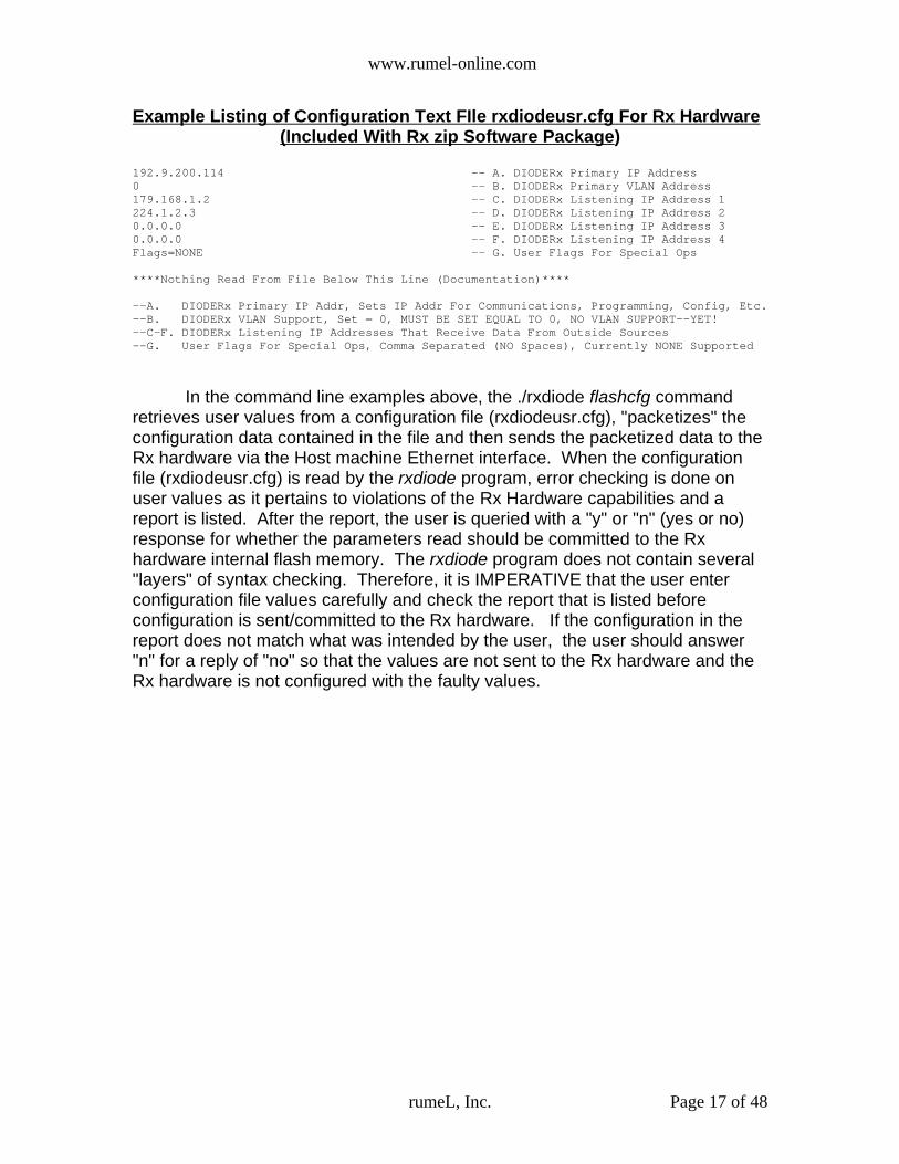
Example Listing of Configuration Text FIle rxdiodeusr.cfg For Rx Hardware(Included With Rx zip Software Package)
192.9.200.114 -- A. DIODERx Primary IP Address0 -- B. DIODERx Primary VLAN Address 179.168.1.2 -- C. DIODERx Listening IP Address 1224.1.2.3 -- D. DIODERx Listening IP Address 20.0.0.0 -- E. DIODERx Listening IP Address 30.0.0.0 -- F. DIODERx Listening IP Address 4Flags=NONE -- G. User Flags For Special Ops
****Nothing Read From File Below This Line (Documentation)****
--A. DIODERx Primary IP Addr, Sets IP Addr For Communications, Programming, Config, Etc.--B. DIODERx VLAN Support, Set = 0, MUST BE SET EQUAL TO 0, NO VLAN SUPPORT--YET!--C-F. DIODERx Listening IP Addresses That Receive Data From Outside Sources --G. User Flags For Special Ops, Comma Separated (NO Spaces), Currently NONE Supported
In the command line examples above, the ./rxdiode flashcfg commandretrieves user values from a configuration file (rxdiodeusr.cfg), "packetizes" theconfiguration data contained in the file and then sends the packetized data to theRx hardware via the Host machine Ethernet interface. When the configurationfile (rxdiodeusr.cfg) is read by the rxdiode program, error checking is done onuser values as it pertains to violations of the Rx Hardware capabilities and areport is listed. After the report, the user is queried with a "y" or "n" (yes or no)response for whether the parameters read should be committed to the Rxhardware internal flash memory. The rxdiode program does not contain several"layers" of syntax checking. Therefore, it is IMPERATIVE that the user enterconfiguration file values carefully and check the report that is listed beforeconfiguration is sent/committed to the Rx hardware. If the configuration in thereport does not match what was intended by the user, the user should answer"n" for a reply of "no" so that the values are not sent to the Rx hardware and theRx hardware is not configured with the faulty values.
rumeL, Inc. Page 17 of 48

www.rumel-online.com
Below is the information that is returned to a user when the ./rxdiodeflashcfg command is executed using the rxdiodeusr.cfg file that is shown aboveas the example configuration file.
./rxdiode flashcfg 192.9.200.110 192.9.200.115 ./rxdiodeusr.cfg <return>
Start Communications With DIODERx Interface...Done
Starting Operation: FLASHCFGConfig File rxdiodeusr.cfg Info :
DiodeRx IP Addr = 192.9.200.114VLAN = 0DiodeRx Listening IP Adr #1 = 179.168.1.2DiodeRx Listening IP Adr #2 = 224.1.2.3DiodeRx Listening IP Adr #3 = 0.0.0.0DiodeRx Listening IP Adr #4 = 0.0.0.0Flags = NONEFirmware Version = 1.00
Operating On User Config Space
You Are About To Re-Configure The DIODERx Internal Settings To The Above Configuration!!These Settings Will Overwrite Previous Configuration Settings!!Continue? ('y' or 'n') y
Turning Off Incoming Data Stream ...DoneReading Configuration Section (30 Secs)Clearing Flash Cfg Sector...DoneProgramming Cfg Area Of FLASH (45 Secs)Restarting Data With New Cfg Parameters ... DoneConfig Complete-New Config Parmeters Take Effect Immediately!!
Note that the flashcfg command is sent to Rx hardware with the IP address of 192.9.200.115 but after the flashcfg command the Rx hardware has a new IP address and can only be accessed via the NEW IP address of 192.9.200.114
From the listing above, there are 7 parameters (A-G) that are used tocontrol/configure the Rx hardware for user specific operation.
The syntax for the configuration file rxdiodeusr.cfg is fairly straight forward.All 7 values appear 1 per line LEFT justified. Where an equal sign ("=") appearsthere should be NO spaces between the values on either side of the equal sign.Items A and C through F are Network addresses and should be written assuch-"dot notation". Items B is currently unused and should be set to zero.Finally the flags field, item G, is also unused and should be set to Flags=NONE.Note once again that there are no spaces around the equals sign.
It is in the user's "best interest" to take the file rxdiodeusr.cfg that comes inthe zip package and modify it for their use rather than creating their own. Theflashcfg command takes as its last entry <path and filename>. Therefore, the filerxdiodeusr.cfg can be copied to unique names, with each file containing differentconfiguration values (ie rxdiodeusr_host_A.cfg, rxdiodeusr_host_B.cfg, etc) andpassed in to the flashcfg command as the last parameter <path and filename>.
5.3 Rx Hardware Configuration File Parameter DescriptionIn the configuration file rxdiodeusr.cfg which comes with the software zip
package there are 7 values. These values are listed as items A through H Atthe bottom of the configuration file rxdiodeusr.cfg is a description of each of these
rumeL, Inc. Page 18 of 48

www.rumel-online.com
parameters for quick reference when editing the file. Below is a more detailedexplanation for each parameter
A. Primary IP Address.This is the IP address that the Rx hardware responds to for "pings"
configuration and programming, only. Upon shipment of the Rx hardware portionof the Network Diode, rumeL, Inc defaults this address to 192.9.200.115. Usingthe flashcfg command, a user can change this address to any valid IP addressthey desire. In the example configuration file rxdiodeusr.cfg, included with the zippackage, this address (as in the example above) has been changed to192.9.200.114. After editing and saving the file, run the rxdiode program with theflashcfg command to reset the IP address (and all other parameters) to thoselisted in the configuration file.
B. VLAN AddressSome specifications, including the SDDS specification, includes 802.1Q
VLAN extensions to "group" multicast and unicast data into VLANs for higherthroughput through router networks. Currently the 802.1Q extensions for theNetwork Diode device (both Rx or Tx hardware) are not supported. At a laterdate, new software and firmware downloads will support this option. For now,this field MUST always be set equal to 0.
Finally, when the 802.1Q extensions are supported both the Rx and Txhardware will be able to receive configuration or programming packets with802.1Q VLAN extensions or without-either type will be valid.
C, D, E, F. Target/Listening IP Address #1, #2, #3, #4These configuration items are the IP addresses that are listened to by the
Rx hardware. Any UDP packet, with IP address C, D, E, F as its destinationaddress will be forwarded across the fiber diode interface to the Tx hardware.Size of the packets do not matter, as long as they conform to gigabit ethernetstandards-64 to 1536 bytes. Setting parameters C, D, E, or F to the IP addressof 0.0.0.0 will disable the listening function for that particular configuration entry.IP addresses that are not 0.0.0.0 will enable listening for that configuration entry.Multicast addresses, addresses in the range of 224.1.0.0 to 239.255.255.255(224.0.x.x addresses are reserved) will cause the Rx hardware to issue an IGMPjoin request and respond to IGMP queries. In other words, the Rx hardwarehandles the IGMP protocol messages to constantly allow for data reception fromany Multicast address configured.
H. FlagsCurrently there are no user flag settings. This entry should appear as:
Flags=NONENo spaces before or after the '=' sign.
rumeL, Inc. Page 19 of 48

www.rumel-online.com
5.4 Tx Hardware flashcfg Command
For the Tx hardware, at the command line, help on the flashcfg commandis available by typing:>> ./txdiode flashcfg help <return>
Example usage:./txdiode flashcfg 192.9.200.110 192.9.200.116 ./txdiodeusr.cfg <return>
The commands program and prgclrcfg are used to download firmware tothe Tx hardware. The command flashcfg (flash config) is used to configure thePrimary and Target IP addresses.
The flashcfg command performs configuration on the internal flashmemory. The non-volatile nature of the internal flash means configuration isretained between power cycles.
As previously mentioned, new Tx hardware when delivered will arriveprogrammed with the firmware download txdiode.rpd and have the Primary IPaddresses 192.9.200.116 . A user may change this Primary IP address (andTarget/Listening IP Addresses) using the flashcfg command. If, later, the userthen changes firmware downloads by using the prgclrcfg command, the flashconfiguration area is erased. In erasing the configuration area, the Rx hardwarewill again default back to IP address 192.9.200.116
rumeL, Inc. Page 20 of 48
Syntax: txdiode flashcfg <Host IP Addr> <DiodeTx Primary IP> <Path & Filename>
flashcfg = writes user cfg info to flash memory for retention between power cycles <Host IP Addr> = Dot Notation Of Host Machine IP Addr, Ex. 192.9.200.110 <DiodeTx Primary IP> = Dot Notation Of DiodeTx IP Addr, Ex. 192.168.200.1 <path & filename> = Path & Filename Of Config File That Holds Config Parameters
The 'flashcfg' operation is used to write user config info to flash memory of the DIODETx. This config info is used to configure DIODETx parameters such as Primary and Target IPaddresses. Writing config info to flash allows the user to remove power from the DIODETx and upon next power cycle retain configuration previous to the power cycle.If the flash config area happens to be empty, (normally not the case, all DIODETx units are programmed with default config before shipment) the DIODETx will default to IP address 192.9.200.116

www.rumel-online.com
Example Listing of Configuration Text FIle txdiodeusr.cfg For Tx Hardware(Included With Tx zip Software Package)
192.9.200.117 -- A. TxDiode Module IP Address0 -- B. TxDiode Module VLAN Address 192.9.200.110 -- C1. TxDiode Destination IP Address 10 -- D1. TxDiode Destination VLAN 1 00:30:48:75:79:FC -- E1. TxDiode Destination HW Address 10 -- F1. TxDiode Source Port 129495 -- G1. TxDiode Destination Port 1224.1.2.3 -- C2. TxDIODE Destination IP Address 20 -- D2. TxDiode Destination VLAN 2 00:00:00:00:00:00 -- E2. TxDiode Destination HW Address 20 -- F2. TxDiode Source Port 229495 -- G2. TxDiode Destination Port 2 0.0.0.0 -- C3. TxDIODE Destination IP Address 30 -- D3. TxDiode Destination VLAN 3 00:00:00:00:00:00 -- E3. TxDiode Destination HW Address 30 -- F3. TxDiode Source Port 329495 -- G3. TxDiode Destination Port 30.0.0.0 -- C3. TxDIODE Destination IP Address 40 -- D3. TxDiode Destination VLAN 4 00:00:00:00:00:00 -- E3. TxDiode Destination HW Address 40 -- F3. TxDiode Source Port 429495 -- G3. TxDiode Destination Port 4Flags=NONE -- H. User Flags For Special Ops
****Nothing Read From File Below This Line (Documentation)****
--A. DIODETX Primary IP Addr, Sets IP Addr For Communications, Programming, Config, Etc.--B. DIODETx VLAN Support, Set = 0, MUST BE SET EQUAL TO 0, NO VLAN SUPPORT--YET!--Cx. Target IP Address, IP Address To Send Data (Multicast Addresses Allowed)--Dx. Target VLAN Value, VLAN (802.1Q) Not Support--Yet!! Set = 0--Ex. Target HW Address, MAC/Ethernet Address That Corresponds To IP Address In Cx--Fx. Sending Port Number, Port Number Tx Diode Sends Data From--Gx. Target Port Number, Destination Port Number Where Data is To be Sent--H. Flags, None In Use-Yet Always Set Flags=NONE, No Spaces Around '='
In the command line examples above, the ./txdiode flashcfg commandretrieves user values from a configuration file (txdiodeusr.cfg), "packetizes" theconfiguration data contained in the file and then sends the packetized data to theTx hardware via the Host machine Ethernet interface. When the configurationfile (txdiodeusr.cfg) is read by the txdiode program, error checking is done onuser values as it pertains to violations of the Tx Hardware capabilities and areport is listed. After the report, the user is queried with a "y" or "n" (yes or no)response for whether the parameters read should be committed to the Txhardware internal flash memory. The txdiode program does not contain several"layers" of syntax checking. Therefore, it is IMPERATIVE that the user enterconfiguration file values carefully and check the report that is listed beforeconfiguration is sent/committed to the Tx hardware. If the configuration in thereport does not match what was intended by the user, the user should answer"n" for a reply of "no" so that the values are not sent to the Tx hardware and theTx hardware is not configured with the faulty values.
Below is the information that is returned to a user when the ./txdiodeflashcfg command is executed using the txdiodeusr.cfg file that is shown aboveas the example configuration file.
rumeL, Inc. Page 21 of 48

www.rumel-online.com
./txdiode flashcfg 192.9.200.110 192.9.200.116 ./txdiodeusr.cfg <return>Start Communications With DiodeTx...Done
Starting Operation: FLASHCFGConfig File txdiodeusr.cfg Info :
Tx Diode IP Addr = 192.9.200.117VLAN = 0
Destination Info #1IP Adr = 192.9.200.110 HW Adr = 00:30:48:75:79:FC VLAN = 0Source Port = 0 Destination Port = 29495
Destination Info #2IP Adr = 224.1.2.3 HW Adr = 00:00:00:00:00:00 VLAN = 0Source Port = 0 Destination Port = 29495
Destination Info #3IP Adr = 0.0.0.0 HW Adr = 00:00:00:00:00:00 VLAN = 0Source Port = 0 Destination Port = 29495
Destination Info #4IP Adr = 0.0.0.0 HW Adr = 00:00:00:00:00:00 VLAN = 0Source Port = 0 Destination Port = 29495
Flags = NONEFirmware Version = 1.00
Operating On User Config Space
You Are About To Re-Configure The DIODETx Internal Settings To The Above Configuration!!These Settings Will Overwrite Previous Configuration Settings!!Continue? ('y' or 'n') y
Turning Off Incoming Data Stream ...DoneReading Configuration Section (30 Secs)Clearing Flash Cfg Sector...DoneProgramming Cfg Area Of FLASH (45 Secs)Restarting Data With New Cfg Parameters ... DoneConfig Complete-New Config Parmeters Take Effect Immediately!!
Note that the flashcfg command is sent to Tx hardware with the IP address of 192.9.200.116 but after the flashcfg command the Tx hardware has a new IP address and can only be accessed via the NEW IP address of 192.9.200.117
From the listing above, there are 23 parameters (A,B,C1-G1,C2-G2,C3-G3,C4-G4,H) that are used to control/configure the Tx hardware for user specificoperation.
The syntax for the configuration file txdiodeusr.cfg is fairly straight forward.All 23 values appear 1 per line LEFT justified. Where an equal sign ("=") appearsthere should be NO spaces between the values on either side of the equal sign.Items A, C1, C2, C3, and C4 are Network IP addresses and should be written assuch-"dot notation". Items B, D1, D2, D3, and D4 are currently unused andshould be set to zero.Items E1, E2, E3, and E4 are Hardware or MAC addresses for the correspondingCx IP address. These values should be written as 6 hexadecimal numbers thatare colon separated. Finally the flags field, item H, is also unused and should beset to Flags=NONE. Note once again that there are no spaces around the equalssign.
rumeL, Inc. Page 22 of 48

www.rumel-online.com
It is in the user's "best interest" to take the file txdiodeusr.cfg that comes inthe zip package and modify it for their use rather than creating their own. Theflashcfg command takes as its last entry <path and filename>. Therefore, the filetxdiodeusr.cfg can be copied to unique names, with each file containing differentconfiguration values (ie txdiodeusr_host_A.cfg, txdiodeusr_host_B.cfg, etc) andpassed in to the flashcfg command as the last parameter <path and filename>.
5.5 Tx Hardware Configuration File Parameter DescriptionIn the configuration file txdiodeusr.cfg which comes with the software zip
package there are 23 values. These values are listed as items A through H Atthe bottom of the configuration file txdiodeusr.cfg is a description of each of theseparameters for quick reference when editing the file. Below is a more detailedexplanation for each parameter
A. Primary IP Address.This is the IP address that the Tx hardware responds to for "pings"
configuration and programming, only. Upon shipment of the Tx hardware portionof the Network Diode, rumeL, Inc defaults this address to 192.9.200.116. Usingthe flashcfg command, a user can change this address to any valid IP addressthey desire. In the example configuration file txdiodeusr.cfg, included with the zippackage, this address (as in the example above) has been changed to192.9.200.117. After editing and saving the file, run the txdiode program with theflashcfg command to reset the IP address (and all other parameters) to thoselisted in the configuration file.
B. VLAN AddressSome specifications, including the SDDS specification, includes 802.1Q
VLAN extensions to "group" multicast and unicast data into VLANs for higherthroughput through router networks. Currently the 802.1Q extensions for theNetwork Diode device (both Rx or Tx hardware) are not supported. At a laterdate, new software and firmware downloads will support this option. For now,this field MUST always be set equal to 0.
Finally, when the 802.1Q extensions are supported both the Rx and Txhardware will be able to receive configuration or programming packets with802.1Q VLAN extensions or without-either type will be valid.
Cx, Dx, Ex, Fx, Gx Target/Destination Network Config (where x is 1 to 4)Configuration parameters Cx, Dx, Ex, Fx, Gx represent the information needed toredirect UDP packets that were received via the fiber diode interface and will beresent via the Tx hardware gigabit ethernet. The Rx hardware accepts a UDPpacket, strips the packet headers of data and fills them in with the values of 1, 2,3, or 4 corresponding to which listening address it was received on. Thestripped packet is then sent across the fiber diode to the Tx hardware. The Txhardware receives the stripped packet and decodes the value of 1, 2, 3, or 4 thatis placed in the packet header by the Rx hardware. The Tx hardware then
rumeL, Inc. Page 23 of 48

www.rumel-online.com
inserts the values that are listed as Cx, Dx, Ex, Fx, and Gx into the packetheader, where x corresponds to 1, 2, 3, or 4 that is in the stripped packet header.Finally, once all of the packet header values are filled in, the Tx hardware sendsthe newly created packet header and data out the Tx hardware Gigabit Ethernetinterface with the new packet header of:
IP address of Cx, VLAN number Dx, Hardware/Mac address Ex, sending Port Fx, and destination Port Gx.
Where x represents a value of 1, 2, 3, or 4. Note that at this time all VLANvalues Dx should be set to 0. VLAN (802.1Q) support is not present—at thistime.
Cx is the destination IP address. This value should be entered vianetwork “Dot” notation. It corresponds to the Target/Destination IP addresswhere data will be forwarded.
VLAN value Dx is currently not supported and should be set equal to 0Hardware/MAC address Ex corresponds to the Hardware/MAC address of
the IP address in Cx. This value should be listed as a 6 byte hexadecimal valuethat is colon separated. See the “Communications” section for more details onhow to determine this value for a given IP address. If the destination IP addressfor Cx happens to be a Multicast address then the Hardware/MAC address Exshould be set to 00:00:00:00:00:00. Multicast IP addresses have uniqueHardware/MAC addresses and the value Ex will be computed by the Txhardware program txdiode. In other words, for Multicast Destination IPaddresses Cx the user simply sets the Ex parameter to 00:00:00:00:00:00.Refer to the section of Determining Hardware/MAC Addresses for moreinformation on how to determine this value.
The sending Port parameter Fx is added to the packet header as thesending port of the data. For SDDS specifications this value should be 0. But,users may want to set this value to known good sending ports that are commonin there network. Or if running a single computer to interface to the Tx hardware,set the Fx parameter such that it does not interfere with other ports that are beingused. Note, the Tx hardware program, txdiode, uses sending port 1300 forconfiguration communications. This value of 1300 should be avoided so as notto conflict with the txdiode program. Parameter Fx, the sending port value shouldbe entered as a decimal value.
The destination port parameter Gx, is the port that data will be received onby a host machine connected to the Tx hardware Gigabit Ethernet connection.This port number is important and will be needed when transferring a file, oracquiring data via the Tx hardware software txdiode. The txdiode usesdestination port value of 2300 for configuration communications. Therefore, useof this number should be avoided to prevent conflicts with the txdiode program.Parameter Gx, the destination port value should be entered as a decimal value.
rumeL, Inc. Page 24 of 48

www.rumel-online.com
H. FlagsCurrently there are no user flag settings. This entry should appear as:
Flags=NONENo spaces before or after the '=' sign.
5.6 Rx & Tx Hardware query and qrywcfg Commands
For the Rx hardware, at the command line, help on the query or qrywcfgcommands is available by typing:>> ./rxdiode query help <return> OR ./rxdiode qrywcfg help <return> Will display the following:
The query command displays the current firmware download, the firmwareversion number, and the contents of the current configuration region back to theuser. In other words, it is a way of reading back what was written to the flashconfiguration area using the flashcfg command.
The qrywcfg (query with configuration) command will cause the sameinformation to be reported back to the user, but once reported, the Rx hardwarewill be instructed to re-load configuration information. The use for this commandwill be made apparent in the "Catch-22" section of this document.Below is an example of the information that is returned to a user when the queryor qrywcfg command is executed. The example below is for the Rx hardware thatwas flash configured with the flashcfg command using the rxdiodeusr.cfg file inthe zip package.
rumeL, Inc. Page 25 of 48
Syntax: rxdiode query <Host IP Addr> <DIODERX IP Addr>
query OR qrywcfg = Flash Configuration Query Utility <Host IP Addr> = Dot Notation Of Host Machine IP Addr, Ex. 192.9.200.110 <DIODERX IP Addr> = Dot Notation Of DIODERX IP Addr, Ex. 192.168.200.1
The 'query' operation is used to retrieve the Firmware version number and the FLASH configuration settings for review by a user. The information displayed givesthe last configuration that was written to the flash memory using the 'flashcfg' operation for the current download of firmware.
The 'qrywcfg' operation gives the same query info as listed above for the 'query' command. In addition, once the query information has been reported to the user the 'qrywcfg' command will reload the configuration settings that were reported.

www.rumel-online.com
>> ./rxdiode query 192.9.200.110 192.9.200.114 <return>
Start Communications With DIODERx Interface...DoneStarting Operation: QUERYTurning Off Incoming Data Stream ...Done
********************** DIODERX Query Info **********************DIODERx Hardware Type
DIODERxR1 Firmware Download Info:
Current Firmware Download - rxdiode.rpdFirmware Version = 1.00
User Flash Config Values: DIODERx IP Address = 192.9.200.114VLAN Value = 0DIODERx Listening IP Addr #0 = 179.168.1.2DIODERx Listening Vlan #0 = 0DIODERx Listening IP Addr #1 = 224.1.2.3DIODERx Listening Vlan #1 = 0DIODERx Listening IP Addr #2 = 0.0.0.0DIODERx Listening Vlan #2 = 0DIODERx Listening IP Addr #3 = 0.0.0.0DIODERx Listening Vlan #3 = 0Flags = NONE
*********************
Turning ON Incoming Data Stream ...Done
For the Tx hardware, at the command line, help on the query or qrywcfgcommands is available by typing:>> ./txdiode query help <return> OR ./txdiode qrywcfg help <return> Will display the following:
The query command displays the current firmware download, the firmwareversion number, and the contents of the current configuration region back to theuser. In other words, it is a way of reading back what was written to the flashconfiguration area using the flashcfg command.
rumeL, Inc. Page 26 of 48
Syntax: txdiode query <Host IP Addr> <DIODETX IP Addr>
query OR qrywcfg = Flash Configuration Query Utility <Host IP Addr> = Dot Notation Of Host Machine IP Addr, Ex. 192.9.200.110 <DIODETX IP Addr> = Dot Notation Of DIODETX IP Addr, Ex. 192.168.200.1
The 'query' operation is used to retrieve the Firmware version number and the FLASH configuration settings for review by a user. The information displayed givesthe last configuration that was written to the flash memory using the 'flashcfg' operation for the CURRENT download of firmware.
The 'qrywcfg' operation gives the same query info as listed above for the 'query' command. In addition, once the query information has been reported to the user the 'qrywcfg' command will reload the configuration settings that were reported.
www.rumel-online.com
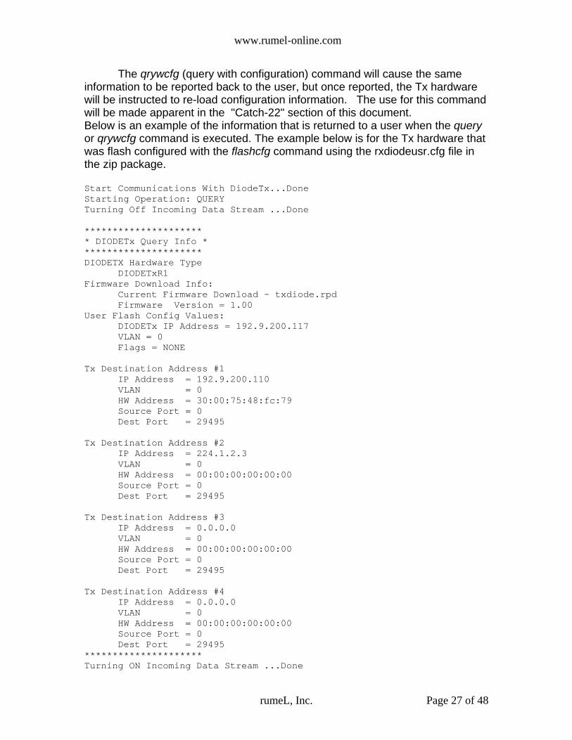
The qrywcfg (query with configuration) command will cause the sameinformation to be reported back to the user, but once reported, the Tx hardwarewill be instructed to re-load configuration information. The use for this commandwill be made apparent in the "Catch-22" section of this document.Below is an example of the information that is returned to a user when the queryor qrywcfg command is executed. The example below is for the Tx hardware thatwas flash configured with the flashcfg command using the rxdiodeusr.cfg file inthe zip package.
Start Communications With DiodeTx...DoneStarting Operation: QUERYTurning Off Incoming Data Stream ...Done
********************** DIODETx Query Info **********************DIODETX Hardware Type
DIODETxR1 Firmware Download Info:
Current Firmware Download - txdiode.rpdFirmware Version = 1.00
User Flash Config Values: DIODETx IP Address = 192.9.200.117VLAN = 0Flags = NONE
Tx Destination Address #1IP Address = 192.9.200.110VLAN = 0HW Address = 30:00:75:48:fc:79Source Port = 0Dest Port = 29495
Tx Destination Address #2IP Address = 224.1.2.3VLAN = 0HW Address = 00:00:00:00:00:00Source Port = 0Dest Port = 29495
Tx Destination Address #3IP Address = 0.0.0.0VLAN = 0HW Address = 00:00:00:00:00:00Source Port = 0Dest Port = 29495
Tx Destination Address #4IP Address = 0.0.0.0VLAN = 0HW Address = 00:00:00:00:00:00Source Port = 0Dest Port = 29495
*********************Turning ON Incoming Data Stream ...Done
rumeL, Inc. Page 27 of 48

www.rumel-online.com
5.7 Rx Hardware transmitfile, and Tx Hardware receivefile CommandsThe Rx hardware transmitfile and Tx hardware receivefile were designed
to be used together to allow a user to transfer a file from the Rx (low side) to theTx (high side) controlling host. These two commands work with a definedprotocol that uses block data transfers, delays and duplicate transfers to providefor a high degree of success in transferring the entire file.
At the command line, help on the Tx hardware executable txdiodecommand receivefile is available by typing: >> ./txdiode receivefile help <return>Will display the following:
For file transfers across the rumeL, Inc. Network Diode the txdiodereceivefile command should be executed. The receivefile command takes as itsparameters:
<Host IP Addr> <DIODETX IP Addr> <Path Name> <Rx Address> <Rx Port>
<Host IP Addr> is the IP address (in network “dot” notation) of the host machinewhere the txdiode program is being executed.
<DIODETX IP ADDR> is the Primary IP address of the Tx hardware, in dotnotation
<Path Name> is the subdirectory on the host machine where the user would likethe data file stored after the transfer. There should be NO trailing “slash” afterthis parameter. Valid examples are /data11/folder or /home/data etc. AnINVALID example would be /data11/folder/ .
<Rx Address> is the destination/target address of where the Tx hardware issending the data. In a majority of the situations, this parameter will be the sameas the <Host IP Addr> parameter-which is simply the IP address of the hostsystem where the txdiode program resides and files are being stored to the
rumeL, Inc. Page 28 of 48
Syntax: txdiode receivefile <Host IP Addr> <DIODETX IP Addr> <Path Name> <Rx Address> <Rx Port>
receivefile = acquire data, sent by DIODERx code, from the DIODETX and store to file <Host IP Addr> = Dot Notation Of Host Machine IP Addr, Ex. 192.9.200.110 <DIODETX IP Addr> = Dot Notation Of DIODETX IP Addr, Ex. 192.168.200.1 <path name> = Path (SubDirectory) Where Data is to be Stored<Rx Address> = IP Address Where DiodeTx is Sending Data <Rx Port> = Receive (Destination) Port Number
The 'receivefile' operation opens a receive connection from the IP address of <Rx Address>and the port number is specified as <Rx Port>.Data acquisition is to file of filename contained in the transferred data. The file is stored in the directory listed as <Path Name>.

www.rumel-online.com
directory of <Path Name>. This parameter <Rx Address> is listed here andneeds to entered for the case that this parameter may be a Multicast addressthat was configured as a target/destination IP address using the flashcfgcommand. This parameter should be entered in dot notation.
<Rx Port> is the destination port number to which the Tx hardware is sendingdata. It corresponds to the configuration settings that where entered, incombination with <Rx Address> using the flashcfg command.
The Tx hardware txdiode receivefile command should be started firstbefore using the Rx hardware rxdiode transmitfile command. When started, thetxdiode receivefile command runs continuously. It listens for connections to theIP address and port specified. When a connection is made, it acquires the dataand stores it to a file. Then it moves back to its “listening” state waiting for thenext connection. A count is maintained to show the number of files transferredand any losses of data for each particular transfer. See the sections titledAddress Re-Mapping and Network Diode File Transfer for more information.
At the command line, help on the Rx hardware executable rxdiodecommand transmitfile is available by typing: >> ./rxdiode transmitfile help <return>Will display the following:
For file transfers across the rumeL, Inc. Network Diode the rxdiodetransmitfile command should be executed AFTER the txdiode receivefilecommand has been executed on the Tx hardware software host.
The transmitfile command takes as its parameters:
rumeL, Inc. Page 29 of 48
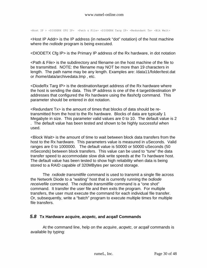
Syntax:rxdiode transmitfile <Host IP > <DIODERX CFG IP> <Path & File> <DIODERX Targ IP> <Redundant Tx> <BlkWait>
transmitfile = transmits file to DIODERX then to DIODETX and store to file <Host IP Addr> = Dot Notation Of Host Machine IP Addr, Ex. 192.9.200.110 <DIODERX CFG IP Addr> = Dot Notation Of DIODERX Config IP Addr, Ex. 192.168.200.1 <path & filename> = Path & Filename For Data File To Transmit<DIODERX RX IP Addr> = Dot Notation Of DIODERX Listening IP Addr, Ex. 192.168.200.2 <Redundant Tx> = OPTIONAL Number of Times To Resend Data Packet, Default = 2<Block Wait> = OPTIONAL Amount of Wait Time (uSec) Between Block Send, Default = 500000
The 'transmitfile' operation opens a transmit connection to one of the four receive IP Addresses of the DiodeRx. Once successfully opened the filetrans operation sends a file via UDP packets to corresponiding open socket on the DiodeRx. Using the parameter <Redundant Tx> a user can optionally specify the number or redundant transmits of data within the file to guarantee the high probability of success for complete file transfer. If not specified the default number of redundant transmits is 2. Which means the total number of times the file will be transmitted is 3. Also, to 'tune' the file transfer and to again provide for high reliability the parameter <Block Wait> is provided as the number of uSec to wait between block transfers.This block wait time allows the receiving disks time to store data. The default value for this parameter is 50000 uSec.
www.rumel-online.com
<Host IP > <DIODERX CFG IP> <Path & File> <DIODERX Targ IP> <Redundant Tx> <Blk Wait>
<Host IP Addr> is the IP address (in network “dot” notation) of the host machinewhere the rxdiode program is being executed.
<DIODETX Cfg IP> is the Primary IP address of the Rx hardware, in dot notation
<Path & File> is the subdirectory and filename on the host machine of the file tobe transmitted. NOTE: the filename may NOT be more than 19 characters inlength. The path name may be any length. Examples are: /data11/folder/test.dator /home/data/archivedata.tmp , etc.
<DiodeRx Targ IP> is the destination/target address of the Rx hardware wherethe host is sending the data. This IP address is one of the 4 target/destination IPaddresses that configured the Rx hardware using the flashcfg command. Thisparameter should be entered in dot notation.
<Redundant Tx> is the amount of times that blocks of data should be re-transmitted from the host to the Rx hardware. Blocks of data are typically 1Megabyte in size. This parameter valid values are 0 to 10. The default value is 2. The default value has been tested and shown to be highly successful whenused.
<Block Wait> is the amount of time to wait between block data transfers from thehost to the Rx hardware. This parameters value is measured in uSeconds. Validranges are 0 to 1000000. The default value is 50000 or 50000 uSeconds (50mSeconds) between block transfers. This value can be used to “tune” the datatransfer speed to accommodate slow disk write speeds at the Tx hardware host.The default value has been tested to show high reliability when data is beingstored to a RAID capable of 320MBytes per second storage.
The rxdiode transmitfile command is used to transmit a single file acrossthe Network Diode to a “waiting” host that is currently running the txdiodereceivefile command. The rxdiode transmitfile command is a “one shot”command. It transfer the user file and then exits the program. For multipletransfers, the user must execute the command for each individual file transfer.Or, subsequently, write a “batch” program to execute multiple times for multiplefile transfers.
5.8 Tx Hardware acquire, acqwtc, and acqall Commands
At the command line, help on the acquire, acqwtc, or acqall commands isavailable by typing:
rumeL, Inc. Page 30 of 48

www.rumel-online.com
>> ./txdiode acquire help <return> OR ./txdiode acqwtc help <return> OR./txdiode acqall help <return> Will display the following:
The acquire, acqwtc, and acqall commands are implemented in thetxdiode program to acquire SDDS data-UDP packets with specific port numbers,size, and data headers. The use of these 3 commands have been implementedto work with any piece of hardware that generates the SDDS protocol. Specialfeatures have been added to acquire data from rumeL, Inc's GIGEXD(www.rumel-online.com/RI-GIGEXD.htm Note extension is .htm not .html) whichgenerates SDDS network data from various analog and digital inputs. Thesecommands are provided in the txdiode program to collect SDDS data and store itto a user specified file.
The acquire command allows a user to bring into a Host system SDDSgenerated data and store it to a file. The parameters for the acquire commandare:<Host IP Addr> IP address of the Host System<GigE IP Addr> IP address of the DIODETX (set with flashcfg command)<Path & Filename> Path & Filename Of Where Data is to be stored on the Host machine<MC Address> The multicast Address from which to acquire data. This is themulticast Address of the Target IP address of the DIODETX<file size> The amount of data to acquire in 1k chunks (setting this value to2048 will acquire 2 MBytes of data)All of these parameters must be present for data to be acquired from the Txhardware.
rumeL, Inc. Page 31 of 48
Syntax: txdiode acquire <Host IP Addr> <DIODETX IP Addr> <Path & Filename> <MC Address> <Rx Port> <file size>
acquire OR acqwtc OR acqall = acquire data from the DIODETX and store to file <Host IP Addr> = Dot Notation Of Host Machine IP Addr, Ex. 192.9.200.110 <DIODETX IP Addr> = Dot Notation Of DIODETX IP Addr, Ex. 192.168.200.1 <path & filename> = Path & Filename Data File Where Data is to be Stored<MC Address> = Multicast Address Of DiodeTx To Acquire Data <Rx Port> = Receive (Destination) Port Number <file size> = Size Of File To Acquire Data (In KBytes)
The 'acquire' operation opens a multicast receive connection (sends out a Join Request) Data acquisition is to file and for a duration as specified by the user. Only the SDDS Data portion is acquired. The SDDS header, including timecode information, is discarded.
The 'acqall' operation opens a multicast receive connection (sends out a Join Request) Data acquisition is to file and for a duration as specified by the user. All of the SDDS/UDP packet is acquired (56 Bytes Header + 1024 Bytes Data = 1080 Bytes Per Packet)Unlike the 'acquire' or 'acqwtc' operations the 'acqall' operation does NOT Endian convertthe SDDS header (timecode) or SDDS data. Endian conversion must be performed by a userapplication on the data written to file
The 'acqwtc' operation adds 16 bytes of Timecode info before each 1KByte of data. to the acquired file. Data block sizes are in 1040 bytes with the first 8 bytes being the actual timecode. Bytes 9-15 are not used (TBD) and can be ignored. Byte 16 of the Timecode info specifies whether the Timecode in bytes 1-8 is valid. If byte 16 is 0xC0 then the timecode is valid and applies to the 1st sample of data in the 1K blockafter the current 16 byte Timecode info field. If the 16th byte is 0x00 then the Timecodeis not valid for the current block of 1KBytes and can be ignored.******************************************************************Bytes 1-8 TC**Bytes 9-15 TBD**Byte 16 Valid TC Marker**Bytes 17-1040 Data**REPEAT PATTERN******************************************************************

www.rumel-online.com
It is important to note the multicast packets that is SDDS are UDPprotocol. SDDS format is simply a UDP protocol packet of 1080 bytes. The first56 bytes of the 1080 bytes is the SDDS header and remaining 1024 bytes aredata. The 56 bytes of SDDS contains a number of fields one of wich is the timecode. Using the acquire command, the 56 bytes of SDDS header is discardedand the 1024 bytes of data is written to the path and filename listed as the thirdcommand argument. Therefore, using the acquire command ONLY writes to file the data. It does NOT write the associated time code to the file. The acqall command writes the entire 1080 bytes of SDDS header and data to file. In other words, the acqall command writes the entire UDP packet payload tothe file. This command has the fastest disk write operations because the SDDSdata is not manipulated by the software. Instead, it is read from the GigabitEthernet port and immediately written to disk. It is the responsibility of a user'sapplication to remove time code for the SDDS header and to do endianconversion on both the time code and data-if needed. The 2nd byte of theSDDS header, byte #1, is the Data Format ID Byte. If this byte is 0x08 then theSDDS data portion is BYTE represented and the user application does not needto do endian conversion. If the Data Format ID Byte is 0x10 then the SDDS dataportion is 16 BIT represented and the user application MUST perform big-endianto little-endian conversion by swapping every other byte. When SDDS data is 8bit or complex 8 bit samples the SDDS data will be BYTE represented. Whenthe SDDS data is 16 bit or complex 16 bit samples the SDDS data will be 16 bitrepresented-and endian conversion will need to be done.
In the SDDS header, time code occupies byte #4 through #15. These 16bytes must always be endian converted regardless of the SDDS data format.The endian conversion should be applied to all 16 bytes. In other words, byte #0of the 16 bytes should be swapped with byte #15. Byte #1 should be swappedwith byte #14, and so on. Once this is done, the 16 bytes of time code take theform of time code when using the acqwtc command below. ( The first 8 bytes arethe time code value, next 7 bytes are RFU and should be ignored, finally the 16thbyte will be the time code Validation Marker).The acqwtc (acquire with time code) command removes time code from the SDDS header and then writes it, with the SDDS data portion of packet, to the fileindicated by the user. The time code portion of the SDDS header is 16 bytes.Therefore, for each packet that is received from the SDDS source (GIGEXD) 16bytes of time code will be written to file followed by 1024 bytes of data-for a totalof 1040 bytes per packet.
For the 16 bytes of time code written, only the first 8 bytes are actually thetime code value. The next 7 bytes are Reserved for Future Use and should beignored. Finally, the 16th byte written to file will be the time code ValidationMarker. The time code Validation Marker will be one of two values. If the valueis 0x00 then the time code present in bytes 1-8 is not valid for the current 1024bytes of data that follow the 16 bytes of time code information. If the time codeValidation Marker is 0xC0 then the time code in bytes 1-8 is valid and applies tothe FIRST sample of data in the 1024 bytes of data that follow the current timecode information.
rumeL, Inc. Page 32 of 48

www.rumel-online.com
Sample RateThe Sample rate of the data is a field in the SDDS header portion of the
packet. The sample rate is offset 24 bytes from the start of the SDDS header ineach packet and is 8 bytes long in Big Endian format. This eight byte value is a2's complement number with the LSBit representing (125MHz/2^63). In otherwords:From the SDDS Specification, Value = (sample rate/125Mhz) * 2^63
Packet CountA modulo 31 counter has been placed in each SDDS header portion of the
packet. The counter value conforms to the SDDS specification, is represented inbig-endian format, and occupies the 3rd and 4th bytes of each packet. The first5 bits of the counter count from 0 to 30 and then "roll over". The next 11 bitscount the number of roll overs of the 5 bit modulo 31 bit counter. Having amodulo 31 counter provides for easy detection of lost packets due to host bufferlimitations.
All the acquire commands, acquire, acqwtc, and acqall check the packetcount of arriving packets to determine if data has been lost. At the end of andacquisition, the amount of packets lost during acquisition will be output to thescreen for the user.
6.0 Communications
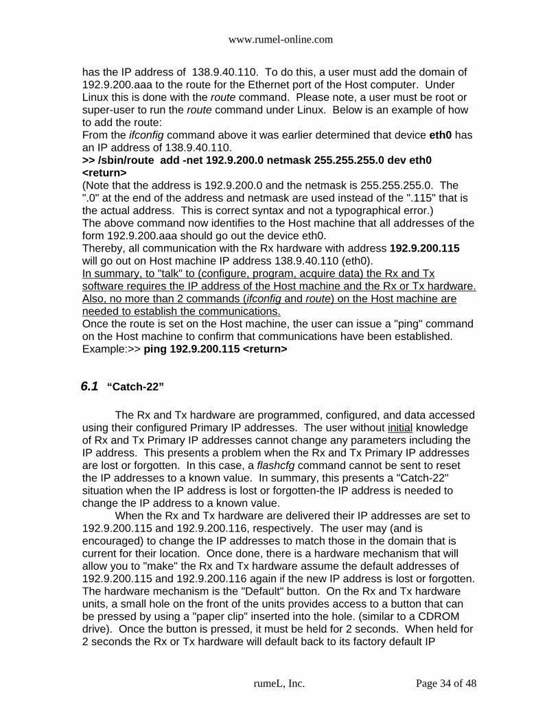
From the parameters of the rxdiode and txdiode programs above, the usermust know two facts before they can use the these programs:1) The IP address of the Host Machine2) The IP address of the Rx and Tx hardware.The Host machine IP address can be found/modified by using the ifconfigcommand under Linux. A user must be root or super-user to run the ifconfigcommand under Linux. Example:>> /sbin/ifconfig <return> The above command will report back the Ethernet devices and their IPaddresses.The Rx and Tx hardware has there IP addresses set at the time of delivery to afactory default value of 192.9.200.115 and 192.9.200.116, respectively. (Theseaddresses can be changed by the user using the rxdiode and txdiode programs,and the flashcfg command to any IP address the user wishes-see the flashcfgcommand under the "Commands" section). Also the Rx and Tx hardware have aunique way of setting their IP addresses to the factory defaults in case the Rxand/or Tx hardware IP addresses are lost or forgotten. (See the "Catch-22"section) As an example, assume that the IP address of the Host machine is 138.9.40.110and the Rx hardware is newly received and is programmed with it's default IPaddress of the 192.9.200.115. In order for the Host machine to "talk" to the Rxhardware a "route" must be added for the Ethernet port on the Host machine that
rumeL, Inc. Page 33 of 48
www.rumel-online.com
has the IP address of 138.9.40.110. To do this, a user must add the domain of192.9.200.aaa to the route for the Ethernet port of the Host computer. UnderLinux this is done with the route command. Please note, a user must be root orsuper-user to run the route command under Linux. Below is an example of howto add the route:From the ifconfig command above it was earlier determined that device eth0 hasan IP address of 138.9.40.110.>> /sbin/route add -net 192.9.200.0 netmask 255.255.255.0 dev eth0<return>(Note that the address is 192.9.200.0 and the netmask is 255.255.255.0. The".0" at the end of the address and netmask are used instead of the ".115" that isthe actual address. This is correct syntax and not a typographical error.)The above command now identifies to the Host machine that all addresses of theform 192.9.200.aaa should go out the device eth0.Thereby, all communication with the Rx hardware with address 192.9.200.115will go out on Host machine IP address 138.9.40.110 (eth0).In summary, to "talk" to (configure, program, acquire data) the Rx and Txsoftware requires the IP address of the Host machine and the Rx or Tx hardware.Also, no more than 2 commands ( ifconfig and route ) on the Host machine are needed to establish the communications.Once the route is set on the Host machine, the user can issue a "ping" commandon the Host machine to confirm that communications have been established.Example:>> ping 192.9.200.115 <return>
6.1 “Catch-22”
The Rx and Tx hardware are programmed, configured, and data accessedusing their configured Primary IP addresses. The user without initial knowledgeof Rx and Tx Primary IP addresses cannot change any parameters including theIP address. This presents a problem when the Rx and Tx Primary IP addressesare lost or forgotten. In this case, a flashcfg command cannot be sent to resetthe IP addresses to a known value. In summary, this presents a "Catch-22"situation when the IP address is lost or forgotten-the IP address is needed tochange the IP address to a known value.
When the Rx and Tx hardware are delivered their IP addresses are set to192.9.200.115 and 192.9.200.116, respectively. The user may (and isencouraged) to change the IP addresses to match those in the domain that iscurrent for their location. Once done, there is a hardware mechanism that willallow you to "make" the Rx and Tx hardware assume the default addresses of192.9.200.115 and 192.9.200.116 again if the new IP address is lost or forgotten.The hardware mechanism is the "Default" button. On the Rx and Tx hardwareunits, a small hole on the front of the units provides access to a button that canbe pressed by using a "paper clip" inserted into the hole. (similar to a CDROMdrive). Once the button is pressed, it must be held for 2 seconds. When held for2 seconds the Rx or Tx hardware will default back to its factory default IP
rumeL, Inc. Page 34 of 48

www.rumel-online.com
addresses of 192.9.200.115 or 192.9.200.116, respectively, and any data flowwill be turned off.
After the Rx or Tx hardware is returned to its factory default IP address of192.9.200.115 or 192.9.200.116 a query command should be run. The querycommand will report back the Primary IP address .(along with other informationabout the firmware download, Target IP addresses, etc..) configured by the userusing the flashcfg command.
After the query command, the user programmed IP address is known. Atthis point the qrywcfg command can be run to restart the module with its currentconfiguration parameters including the user programmed IP address that wasreported with the query command. Or, a flashcfg command can be run using thedefault IP addresses of 192.9.200.115 or 192.9.200.116 as the Rx or Tx PrimaryIP addressees and the Rx or Tx hardware can be reconfigured to a new IPaddress.
In general, in this situation a Host machine "ping" operation is anextremely useful tool. Once the default button is pressed, a user can execute:>> ping 192.9.200.115 <return> OR ping 192.9.200.116 <return>The Rx hardware will reply to the 192.9.200.115 address. The Tx hardware willreply to 192.9.200.116. Once the query, and then subsequent qrywcfgcommands are run, the user can then confirm the switch back to their configuredPrimary IP addresses by typing:>> ping <user IP Address> <return>
6.2 Maximizing Tx Hardware to Host Computer Data Transfer Rates
Host machines that configure and receive data from the Tx hardwaretypically do not have their Gigabit Ethernet ports optimized for fast data transferrates. In other words, under Linux, using the standard installed configuration forGigabit Ethernet ports will provide for slow data transfer rates and droppedpackets.
Below is a command that increases the Gigabit Ethernet driver memorybuffer size so that maximum data transfer rates can be realized. Users havetypically gotten the maximum 100MBytes/Sec throughput using this command.The command MUST be run as root or Superuser. Once executed, thecommand only needs to be run once until the next power/reset cycle of the hostmachine.
The command is:>>/sbin/sysctl -w net.core.rmem_max=10485760
Note that the number at the end is 10 Megabytes-this is the new size ofthe allocation buffer. With this value users have been able to obtain maximumdata rates. Larger sizes may be tried but a corresponding change to thetxdiode.c software must be made to take advantage of the new size. At the topof the txdiode.c program file is the declaration:
rumeL, Inc. Page 35 of 48

www.rumel-online.com
#define GIGEMEMBUFSIZE 10485760
This value should be changed to the value that is set by the user using the sysctlcommand above. Then the program txdiode.c should be recompiled -see thesection Build Scripts and the txdiode and rxdiode Executables forcompilation instructions.
6.3 Determining Hardware/Mac Addresses When using the Tx hardware executable txdiode to configure the Tx
hardware, the user for non-Multicast IP addresses must include theHardware/MAC addresses in order for the Tx hardware to forward packets to theTarget IP address. There are 2 methods to determine the Hardware/MAC.
The 1st method is to access the host that has the target IP address. Oncelogged in as root or super-user execute the command:
>> /sbin/ifconfig <return>
A listing similar to the following will appear:
eth0 Link encap:Ethernet HWaddr 00:30:48:75:79:FC inet addr:192.9.200.110 Bcast:192.9.200.255 Mask:255.255.255.0 inet6 addr: fe80::230:48ff:fe75:79fc/64 Scope:Link UP BROADCAST RUNNING MULTICAST MTU:1500 Metric:1 RX packets:1 errors:0 dropped:0 overruns:0 frame:0 TX packets:28 errors:0 dropped:0 overruns:0 carrier:0 collisions:0 txqueuelen:1000 RX bytes:64 (64.0 b) TX bytes:2894 (2.8 KiB) Base address:0x3000 Memory:dd300000-dd320000
eth1 Link encap:Ethernet HWaddr 00:30:48:75:79:FD inet addr:192.9.200.210 Bcast:192.9.200.255 Mask:255.255.255.0 inet6 addr: fe80::230:48ff:fe75:79fd/64 Scope:Link UP BROADCAST MULTICAST MTU:1500 Metric:1 RX packets:0 errors:0 dropped:0 overruns:0 frame:0 TX packets:0 errors:0 dropped:0 overruns:0 carrier:0 collisions:0 txqueuelen:1000 RX bytes:0 (0.0 b) TX bytes:0 (0.0 b) Base address:0x3040 Memory:dd320000-dd340000
lo Link encap:Local Loopback inet addr:127.0.0.1 Mask:255.0.0.0 inet6 addr: ::1/128 Scope:Host UP LOOPBACK RUNNING MTU:16436 Metric:1 RX packets:8 errors:0 dropped:0 overruns:0 frame:0 TX packets:8 errors:0 dropped:0 overruns:0 carrier:0 collisions:0 txqueuelen:0 RX bytes:560 (560.0 b) TX bytes:560 (560.0 b)
From the information above, the host computer has 2 Gigabit Ethernetports: eth0 and eth1. If the user wants the Tx hardware to forward data to eth0then, the user, would specify as one of the Target IP addresses the address192.9.200.110. The Hardware/MAC address is listed under the heading ofHwaddr which is the value 00:30:48:75:79:FC These 6 bytes, colon separatedwould be entered as the configuration parameter Ex to correspond with Cx as the
rumeL, Inc. Page 36 of 48

www.rumel-online.com
Target IP address 192.9.200.110. The source port and destination ports are nowarbitrary and can be set to any that are not currently in use-the user could evenleave these set to the SDDS default of 0 for sending and 29495 as thedestination.
The 2nd method of determining the Hardware/MAC address can be used ifthe user does not have login or root permissions on the host of interest to whichto send data. This is the case where 1 host computer is being used for“configuration” and a 2nd host is being used to collect data. In this case using“ping” to obtain the Hardware/MAC address of the 2nd data host computer can beused.
In this example the configuration host computer is going to ping the datahost computer. Assuming that the data host computer's IP address is192.9.200.103 and the configuration and data hosts are connected via a networkissue the ping command to the data host computer:
>> ping 192.9.200.103 <return>
Once the ping is successful, issue a 2nd command from the configuration hostcomputer:
>> /sbin/arp <return>
The listing returned from the above command will look similar to the listingbelow:
Address HWtype HWaddress Flags Mask Iface192.9.200.1 ether 00:0E:84:BB:35:C0 C eth0192.9.200.103 ether 00:16:41:E3:82:64 C eth0
From the listing of the ARP cache above, the data computer at IP address192.9.200.103 has the Hardware/MAC address of 00:16:41:E3:82:64 . With theinformation of the IP address of 192.9.200.103 and the Hardware/MAC addressof 00:16:41:E3:82:64 the txdiode configuration file (txdiodeusr.cfg) entries Cxand Ex can be filled in. Once configured by the configuration host computer, theTx hardware of the Network Diode will forward data to the data host computer.
rumeL, Inc. Page 37 of 48

www.rumel-online.com
7.0 Address Removal and Re-Mapping
As mentioned in other sections of this document the Network Diodeperforms Address re-mapping of ALL UDP packets that are passed through thedevice. The Rx hardware is configured with 1 Primary IP address and up to 4Target IP addresses. The Primary IP address is ONLY for configuration andprogramming access of the Rx hardware. No data sent to the Primary IPaddress will be forwarded across the fiber diode interface to the Tx hardware.
On the other hand, UDP packets, of any valid Gigabit Ethernet size (64 to1536 bytes) will be forwarded if the packet's IP address matches 1 of the 4Target IP addresses. When a match is made between packet IP address andone of the Rx hardware Target IP address, the packet's Ethernet, IP,and UDPheader are cleared and replaced simply with the value of 1, 2, 3, or 4 for each ofthe fields in the Ethernet, IP, and UDP headers. The value of 1, 2, 3, or 4, that isinserted, corresponds to which Target IP address the received packet hasmatched when it was received by the Rx hardware. Once these values arereplaced (Hardware/MAC address, IP destination and source addresses, UDPdestination and source ports) the information about where the data originated islost and the data can be moved from the low side to the high side circuitry via thefiber diode interface. (Refer to Figure 3)
Once across the fiber diode interface, the packet header that contains thevalue of 1, 2, 3, or 4 is read by the Tx hardware. The Tx hardware uses a lookup table to access the NEW Hardware/MAC address, IP destination address, andUDP destination and source ports at the address of 1, 2, 3, or 4 and then insertsthe new header information. Once the new addresses and port numbers areinserted into the header, the Tx hardware inserts its Primary IP address as thesource IP address. Once all of the addresses and ports are inserted, the Txhardware re-calculates checksums and inserts these into the packet. The packetis now complete and it is sent out the Tx hardware Gigabit Ethernet port to anetwork or host computer.
From the information above, the mapping between Rx hardware Target IPaddresses and Tx hardware Target/Destination IP addresses is simply 1 to 1. Asan example, if a packet is received and its destination IP address matches TargetIP address number 1 of the Rx hardware, it's headers will be stripped and a 1inserted for the fields of the header. The packet will then be sent over the fiberDiode interface where the Tx hardware will look up the Target/Destinationaddresses in location 1, insert these values, and send the packet out the GigabitEthernet port. A user simply has to maintain the 1 to 1 correspondence in theirconfiguration. No information about the Rx hardware IP addresses must beknown by the Tx hardware. The only information that has to be known is whetherto configure the Tx hardware's Target/Destination of 1, 2, 3, or 4 with theinformation discussed above for the flashcfg command.
If the received packet had matched Target IP address 2 of the Rxhardware, then a stripped packet with a value of 2 in the header fields wouldhave been passed through the fiber Diode interface. The Tx hardware wouldthen have retrieved its stored Target/Destination values from location 2, inserted
rumeL, Inc. Page 38 of 48

www.rumel-online.com
these values, and then sent the packet out the Gigabit Ethernet port. Once againmaintaining the 1 to 1 correspondence when Address Re-Mapping the packets.
As additional information the user should note, that what enters the Rxhardware as a unicast packet can be re-mapped on the Tx hardware to a new IPaddress that is in the multicast range. This type of re-mapping would then allowseveral computers to access what was previously a single stream of data. Thereverse is also true. If a packet enters the Rx hardware as a multicast packet itcan be re-mapped by the Tx hardware as a unicast packet. For someapplications this change may be beneficial for data processing.
In summary, the packet address removal provides for information hiding inmoving data from a non-secure to secure environment or visa-versa. Neitherside has knowledge, or is presented information, that could compromise systemson the other side of the Network Diode.
rumeL, Inc. Page 39 of 48
Rx Hardware
Low SideNetwork Data In
1. Incoming IP AddressMatches Any Target IP Addresses 1, 2, 3, or 4 andPacket is UDP type? Yes, Goto 2No, Goto 5
2.Strip Packet Headers
3.Add value 1, 2, 3, or 4 to empty packet headers
4. Forward Packet Across Fiber Diode Interface To Tx Hardware
5. Discard Original Packet
FiberDiode
Tx Hardware
1. Incoming Lookup NumberMatches Configured Entry?Yes, Goto 2No, Goto 5
2.Add Configured IP Addresses
3.Insert, Calculated Checksums
4. Forward Packet Out GigabitEthernet Port To High SideNetwork/Computer
5. Discard Original Packet
High SideNetwork Data Out
Figure 4 – Detail Of Address Re-Mapping

www.rumel-online.com
8.0 Network Diode File TransferAs stated earlier, the Rx and Tx software programs rxdiode and txdiode
provide the user with a file transfer mechanism. The txdiode receivefilecommand the the rxdiode transmitfile command work in cooperation toaccomplish the sending and receiving of files through the Network Diodehardware.
To accomplish file transfer the Tx hardware txdiode receivefilecommand must be executed PRIOR to executing the Rx hardware rxdiodetransmitfile command. The txdiode receivefile command takes as itsparameters:
<Host IP Addr> <DIODETX IP Addr> <Path Name> <Rx Address> <Rx Port>
The parameters as described earlier in the section Rx Hardwaretransmitfile and Tx Hardware receivefile Commands supply the subdirectory(<Path Name>) where the data is to be stored. The <Rx Address> and <RxPort> parameters are 1 of the 4 target/destination IP addresses and destinationports that were configured using the txdiode flashcfg command. These representthe IP address and port number of the host that the Tx hardware will be sendingdata. Typically, the Target/destination IP address is the IP address of the hostcomputer that holds the Tx hardware executable txdiode.
When the txdiode receivefile command executes it waits for a start oftransfer from the Rx hardware rxdiode transmitfile command. The output fromthe txdiode receivefile appears as listed below while waiting for the start:
Start Communications With DiodeTx...DoneStarting Operation: RECEIVEFILE
When the start is received, the txdiode receivefile command prints to the screenthe statistics about the file-filename, size, etc. The output appears as listedbelow:
***************************************************************File Transfer Number = 1Received Valid Start Command, File Transfer Random Number = f9fe981aDiodeRx Firmware Version = 1.00DiodeTx Firmware Version = 1.00Filename To Transfer = testramp.tmpNumber Of Full Blocks For Transfer = 200Packets Per Full Block = 1024Data Size Of Packets = 1024 BytesAdditional Bytes After Full Block Transfers = 512File Transfer Size, Number Of 1K Blocks = 204800, Plus 512 BytesFile Will Be Stored As /data11/xmidas/testramp.tmp
Note that in the communications between the rxdiode transmitfilecommand the the txdiode receivefile command that a random number is passedthat uniquely identifies this file transfer from all others. Also, the size of packets,
rumeL, Inc. Page 40 of 48

www.rumel-online.com
number of packets, number of packets per block, the number of blocks , and anyleft over bytes, that do not fit into the packet transfer size are listed. From theinformation listed the total file size will be 200Megabyte plus an additional 512bytes. Total file transfer size will be 209715712 bytes. Finally, where the file willbe stored and filename are listed. When the transfer is complete moreinformation will be printed that appears as the following example:
Ending File Transfer, Closing File.Total Packets Lost During File Transfer = 0***************************************************************
Here the information that is reported back is the end of the transfer andthe number of packets that were lost during transfer. Any number but 0reported as the number of packets lost represents a loss of data and thefile transfer not completing without loss of data from within the file.
The loss of packets is typically due 1 of 2 reasons, or both.1) The Tx hardware host computer's Gigabit Ethernet interface buffer is too
small and data is being lost at the OS level when buffered.2) The Tx hardware host computer's disk I/O speeds when writing the file is
too slow.
To solve for case 1 of a Gigabit Ethernet buffer overflow, be sure that theCommunications section has been followed concerning setting the GigabitEthernet driver memory buffer to a larger size.
To solve for case 2 the Rx hardware rxdiode transmitfile command has tobe “tuned” to transfer data at a slower rate to accommodate the slow I/O speedof the Tx hardware host system disks. Subsequent information on the rxdiodetransmitfile command will solve case 2.
rumeL, Inc. Page 41 of 48
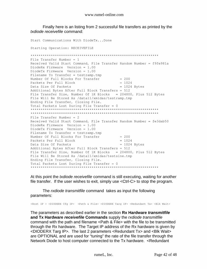
www.rumel-online.com
Finally here is an listing from 2 successful file transfers as printed by thetxdiode receivefile command:
Start Communications With DiodeTx...Done
Starting Operation: RECEIVEFILE
***************************************************************File Transfer Number = 1Received Valid Start Command, File Transfer Random Number = f9fe981aDiodeRx Firmware Version = 1.00DiodeTx Firmware Version = 1.00Filename To Transfer = testramp.tmpNumber Of Full Blocks For Transfer = 200Packets Per Full Block = 1024Data Size Of Packets = 1024 BytesAdditional Bytes After Full Block Transfers = 512File Transfer Size, Number Of 1K Blocks = 204800, Plus 512 BytesFile Will Be Stored As /data11/xmidas/testramp.tmpEnding File Transfer, Closing File.Total Packets Lost During File Transfer = 0******************************************************************************************************************************File Transfer Number = 2Received Valid Start Command, File Transfer Random Number = fe3dab50DiodeRx Firmware Version = 1.00DiodeTx Firmware Version = 1.00Filename To Transfer = testramp.tmpNumber Of Full Blocks For Transfer = 200Packets Per Full Block = 1024Data Size Of Packets = 1024 BytesAdditional Bytes After Full Block Transfers = 512File Transfer Size, Number Of 1K Blocks = 204800, Plus 512 BytesFile Will Be Stored As /data11/xmidas/testsine.tmpEnding File Transfer, Closing File.Total Packets Lost During File Transfer = 0***************************************************************
At this point the txdiode receivefile command is still executing, waiting for anotherfile transfer. If the user wishes to exit, simply use <Ctrl-C> to stop the program.
The rxdiode transmitfile command takes as input the followingparameters:
<Host IP > <DIODERX Cfg IP> <Path & File> <DIODERX Targ IP> <Redundant Tx> <Blk Wait>
The parameters as described earlier in the section Rx Hardware transmitfileand Tx Hardware receivefile Commands supply the rxdiode transmitfilecommand with the path and filename <Path & File> with the file to be transmittedthrough the Rx hardware. The Target IP address of the Rx hardware is given by<DIODERX Targ IP>. The last 2 parameters <Redundant Tx> and <Blk Wait>are OPTIONAL and are used for “tuning” the rate of the file transfer through theNetwork Diode to host computer connected to the Tx hardware. <Redundant
rumeL, Inc. Page 42 of 48

www.rumel-online.com
Tx> is the number of times that a block of data is retransmitted. A block of dataconsists of 1024 packets, where each packet carries 1024 bytes. Therefore, ablock size is equal to 1 Megabyte of data (1048576 bytes). Once transferredonce, the block of data will be re-transmitted <Redundant Tx> number of times.The valid values for <Redundant Tx> are 0 <= <Redundant Tx> <= 10. The Txhardware txdiode receivefile command, recognizes redundant transfers and onlystores the redundant data packets if initial transfer packet(s) did not get stored todisk. Therefore, the only data that gets stored to file is the original data.Redundant data is only used to fill in the “holes” of packets that were lost. Inshort, lower values of <Redundant Tx> will increase the rate of the file transferbut limit the txdiode receivefile command's ability to fill in lost packets on theother side of the Network Diode, thereby reducing the probability of a completefile transfer.
Once again, the parameter <Redundant Tx> is optional. The default valuefor <Redundant Tx> is 2. Through extensive testing the value of 2 has beenshown to create very reliable file transfers.
The final parameter is <Blk Wait> (Block Wait). This parameterrepresents the amount of time, in microseconds (uSec), the rxdiode transmitfilecommand should wait between block transfers. <Blk Wait> is useful in “throttling”data bursts through the Network Diode to a waiting host computer that has slowdisk I/O rates. The valid values for <Blk Wait> are 0 to 250000. Lower values ofblock transfer wait times will increase the rate of file transfer but will require thedisk I/O speed of the host computer connected to the Tx hardware to be greater.Higher values of wait time will allow the host computer connected to the Txhardware to perform disk I/O slower, thereby potentially eliminating the need forfast RAIDs.
And again ,the parameter <Blk Wait> is optional. The default value for<Blk Wait> is 50000. Through extensive testing the value of 50000 has beenshown to create very reliable transfers.
Finally, the parameters <Redundant Tx> and <Blk Wait>, as mentionedabove, are optional. For the rxdiode transmitfile command to function correctlyeither BOTH of the parameters must be specified by the user on the commandline OR neither of the parameters are present. In the case where neither arespecified, the defaults will be used.
Below is a listing of the rxdiode transmitfile command after sending the filetestramp.txt:Start Communications With DIODERx Interface...Done
Starting Operation: TRANSMITFILETotal Packets Per Block = 1024Total Blocks For Transmission = 201Left Over Packets For Transfer = 1Packet Data Size = 1024 BytesData Left Over For Single Transfer = 512 BytesTotal Packets For Transmission = 204801Redundant Packet Transmissions = 2
rumeL, Inc. Page 43 of 48

www.rumel-online.com
Wait 8 Seconds For Receive End File Deletion/Creation1 2 3 4 5 6 7 8
Transfer Status: 1K Blocks Transmitted = 1024, Percent Complete = 0Transfer Status: 1K Blocks Transmitted = 2048, Percent Complete = 0Transfer Status: 1K Blocks Transmitted = 3072, Percent Complete = 1Transfer Status: 1K Blocks Transmitted = 4096, Percent Complete = 1Transfer Status: 1K Blocks Transmitted = 5120, Percent Complete = 2Transfer Status: 1K Blocks Transmitted = 6144, Percent Complete = 2............Transfer Status: 1K Blocks Transmitted = 204801, Percent Complete = 100File Transfer CompleteTotal 1K Blocks Sent = 204801
Note that the default is for an 8 second wait after the rxdiode transmitfilecommand has informed the txdiode receivefile command that a file is to be sent.This delay is to allow time for the host that is executing the txdiode receivefilecommand to open and create the file. Depending on the size of the files, and ifthe user is re-transmitting files to overwrite previous transmitted files on the Tx hardware host computer, 8 seconds of time may not be enough for the Txhardware host computer to delete, re-create, and open the file. In this case,packets will be lost. The user has the option of changing this wait time bymodifying the rxdiode.c source code. If the user searches for the string,STARTWAITTIME, they will find the first occurrence to be the line below:
#define STARTWAITTIME 8
The STARTWAITTIME value is the number of seconds to wait afternotifying the Tx hardware that a file is to be sent BEFORE sending the first data.Increasing this value will allow for more wait time so that the Tx hardware hostcomputer will have enough time to delete a large file, re-create, and open a newfile. After editing the rxdiode.c file, a user must remember to re-compile thesource file rxdiode.c into the executable rxdiode by typing:
>> source rxdiodebuild.lnx <return>
Finally, remember that the need to modify the #define above will onlyoccur if:
1) The file is large.2) The file name already exists on the Tx hardware host computer and
therefore an overwrite is occurring.
rumeL, Inc. Page 44 of 48

www.rumel-online.com
9.0 SecurityFrom the detailed description of the operation of the Network Diode, a
user can see that the Hardware/MAC addresses, IP addresses and port numbersare removed before transfer from the Rx hardware, across the fiber diode, to theTx hardware. Other security features include separate power and groundconnections. As shown in Figure 3, the Rx hardware and Tx hardware haveseparate power connections but what is not shown is that ALL groundconnections are independent. Therefore, all current returns from the Rxhardware flows back through the ground of the Rx hardware power supply. Also,all current returns from the Tx hardware flows back through the ground of the Txhardware power supply. Both pieces of hardware, Rx and Tx hardware, haveindependent power and ground connections. These separate connections allowfor the Tx hardware to be connected to dedicated “high” side power and ground.Also, Rx hardware can be connected to dedicated “low” side power and ground.
rumeL, Inc. Page 45 of 48

www.rumel-online.com
10.0 rumeL, Inc. Network Diode Pictures
Network Diode-Rx & Tx Hardware Separation (Fiber Diode Cable Not Installed)
Network Diode Fiber Diode Link LED (Fiber Cable Installed)
Rx & Tx Hardware Default Holes/Buttons
rumeL, Inc. Page 46 of 48
Rx Hardware Tx Hardware
Rx HardwareGigabit Ethernet
Interface
Tx HardwareGigabit Ethernet
Interface
Rx Fiber Diode(Tx Only)
Tx Fiber Diode(Rx Only)
Rx Fiber DiodeTx Link LEDOFF-No Link
RED-LinkGREEN-Active Tx
Tx Fiber DiodeRx Link LEDOFF-No Link
RED-LinkGREEN-Active Rx
Rx HardwareDefault
Hole/Button
Tx HardwareDefault
Hole/Button

www.rumel-online.com
Rx & Tx Hardware Gigabit Ethernet Link LEDs
1U Rack mount Chassis (Support For 2 Network Diodes)
rumeL, Inc. Page 47 of 48
Rx HardwareGigabit Ethernet
Link LEDOFF-No Link
RED-LinkGREEN-Active Tx
Tx HardwareGigabit Ethernet
Link LEDOFF-No Link
RED-LinkGREEN-Active Tx
Location ForOptional 2nd Unit
Rx HardwarePower Supply
Tx HardwarePower Supply

www.rumel-online.com
Internal Hardware, Power, Ground Isolation
rumeL, Inc. Page 48 of 48
Rx Chassis GroundPlastic Isolation
Tx Chassis GroundPlastic Isolation
Tx IsolatedPower Supply
Rx Isolated Power Supply
Tx HardwareRF Shield
Rx Hardware RF Shield