user’s guide part no. 34501-03 - university of idaho software... · user’s guide part no....
TRANSCRIPT

User’s Guide
Part No. 34501-03
3360 E. LA PALMA AVE, ANAHEIM, CA 92806
P.O. BOX 6150, ANAHEIM, CA 92816-6150
021008
ii Aries User’s Guide
Copyright 1996-2002 Econolite Control Products, Inc. All Rights Reserved No part of this document may be reproduced or quoted without written permission of Econolite Control Products, Inc. Aries is a trademark of Econolite Control Products, Inc. MS-DOS and Windows are registered trademarks of Microsoft Corporation. IBM-PC is a registered trademark of International Business Machines, Inc. All other product names are trademarks or registered trademarks of their respective owners.
Aries User’s Guide iii
Aries® Software License Agreement Econolite Control Products, Inc. (“Econolite”), a California corporation, with offices at 3360 East La Palma, Anaheim, California 92806 agrees to grant and agrees to accept a nonexclusive, nontransferable License to use the Licensed Programs included with this agreement subject to the terms and conditions of this agreement.
Scope of Rights
This agreement grants a nontransferable and nonexclusive right to the use of the programs included with this agreement.
a. To use the licensed programs but only in machine-readable form on a single computer.
b. To use the support material supplied but only as required to support use of the Licensed Programs.
c. To make only as many backup copies of the Licensed Programs in machine-readable form as required supporting use of the Licensed Programs on a single computer. All backup copies must include the copyright notice in the original form as it appears on the Licensed Programs.
d. You may NOT copy, modify, adapt, merge, disassemble, recompile or distribute the software, its documentation or create derivative works based upon the software.
None of the support materials in human-readable form included with the Licensed Programs may be copied in any way. You may print any screen the software allows, but you may not remove any copyright notice generated along with the printing. Copyright notices shall not be removed from any of the Licensed Programs or support materials.
Copyright
The Licensed Programs and support materials included with this agreement are copyrighted. No copies of the Licensed Programs or support materials may be made except for backup purposes and to load the Licensed Programs into a single computer as part of executing the Licensed Program. The Licensed Programs may be installed on more than one computer as long as they are not used simultaneously. If used in a network environment, each workstation on the network using the Licensed Programs must have a separate license agreement.
Restriction on Dissemination
The Licensed Programs and support materials contain confidential information that is the property of Econolite. The Licensed Programs, program concepts or any of the support materials shall not be made available to any other party or organization.
iv Aries User’s Guide
Title
Title to all intellectual property rights including patent, trademark, copyright and trade secret rights and title to all ownership rights and all copies of and all media bearing the Licensed Programs, support materials and program concepts are and shall remain in Econolite.
Non-assignment
The Licensed Programs may not be assigned, delegated, sublicensed, pledged or otherwise transferred to any party without prior written consent from Econolite.
Term
This license is effective until terminated by the user or by Econolite. Upon termination of this license, all copies of the Licensed Programs and support materials shall be immediately delivered to Econolite. To register your software and qualify for future software upgrades, you must fully complete and mail the Aries software registration card not more than ten (10) calendar days from the date product was received. Should you have any questions concerning this Agreement or if you wish to contact Econolite Control Products, Inc. for any reason regarding Aries or other Econolite traffic control system products, please contact: Econolite Control Products, Inc. Customer Service 3360 E. La Palma Avenue Anaheim, CA 92806-2856 Telephone (714) 630-3700 Fax (714) 630-6349
Table of Contents
Aries User’s Guide v
Table of Contents Chapter 1 Getting Started ............................................................................................... 1-1
Hardware............................................................................................................................................1-2 Recommended Computer System for New Purchase ................................................................................... 1-2 Minimum Computer Requirements for Running Aries ................................................................................ 1-2 Compatibility with Equipment in the Field .................................................................................................. 1-2
Installation..........................................................................................................................................1-3 Registry Entries ............................................................................................................................................ 1-3 Mixed Windows NT-2000-XP/95-98 Network Problems ............................................................................ 1-4 Aries File/Comm. Server LAN Setup........................................................................................................... 1-5 Configure Aries Workstation for LAN Setup............................................................................................... 1-8 Renaming Sysevent.rtf ................................................................................................................................. 1-9
Aries Configuration Variables .........................................................................................................1-10 Configuration Variable Summary .............................................................................................................. 1-10 Configuration Variable Tables ................................................................................................................... 1-10
Modem Setup Instructions ...............................................................................................................1-17 Default Command ...................................................................................................................................... 1-17 AT Command Prefix .................................................................................................................................. 1-17
Chapter 2 Aries Introduction .......................................................................................... 2-1 Aries Window ....................................................................................................................................2-1 General Application Features.............................................................................................................2-2
Graphical User Interface............................................................................................................................... 2-2 Multiple Communication Ports .................................................................................................................... 2-2 Multitasking Operations ............................................................................................................................... 2-3 Client Server Model ..................................................................................................................................... 2-3 Distributed Network Support........................................................................................................................ 2-3 Database Management Functions................................................................................................................. 2-3 Monitor Mode............................................................................................................................................... 2-3 Operation Scheduler ..................................................................................................................................... 2-4 Manual Commands....................................................................................................................................... 2-4 Printing/Plotting/Exporting Features............................................................................................................ 2-4 Split Monitor Report .................................................................................................................................... 2-4 Graphic Displays .......................................................................................................................................... 2-5 Data File Compatibility with Zone Monitor IV............................................................................................ 2-5 Operation with Zone Monitor IV.................................................................................................................. 2-5
Chapter 3 Zones Directories............................................................................................ 3-1 Set up Aries Access Codes.................................................................................................................3-1 Set Up the Communications Server ...................................................................................................3-2
Defining a New Zone ................................................................................................................................... 3-3 Editing a Previously Entered Zone............................................................................................................... 3-5
Setting Zone Time..............................................................................................................................3-6 Activate the Communications Server Task........................................................................................3-6 Master Data ........................................................................................................................................3-7
Uploading Master Data................................................................................................................................. 3-7 Aries Data Entry Window ............................................................................................................................ 3-7 Editing Master Data...................................................................................................................................... 3-8 Comparing Master Data ............................................................................................................................... 3-8 Downloading Master Data............................................................................................................................ 3-8
Table of Contents
vi Aries User’s Guide
Chapter 4 Adding, Uploading, Editing and Downloading Intersection Data............ 4-1 Adding an Intersection to a Zone .......................................................................................................4-1 Controller Data...................................................................................................................................4-2
Uploading Controller Data............................................................................................................................ 4-2 Editing ASC/2 Controller Data..................................................................................................................... 4-3 Editing ASC-8000 Controller Data............................................................................................................... 4-4 Compare ASC/2 Controller Data .................................................................................................................. 4-5 Comparing ASC-8000 Controller Data ........................................................................................................ 4-6 Downloading Controller Data....................................................................................................................... 4-6
Chapter 5 Zone Display Setup ........................................................................................ 5-1 Viewing Zone Displays......................................................................................................................5-1 Zone Display Setup............................................................................................................................5-1 Defining Vehicle Movements ............................................................................................................5-2 Modify Vehicle Movements ..............................................................................................................5-2 Saving Zone Displays ........................................................................................................................5-2 Viewing Live Zone Displays .............................................................................................................5-3 Have Only One Active Task Per Zone...............................................................................................5-3
Chapter 6 Intersection Display Setup ............................................................................ 6-1 Starting Intersection Displays ............................................................................................................6-1 Load Intersection Image File .............................................................................................................6-2 Defining Vehicle Movements ............................................................................................................6-3 Defining Pedestrian Symbols.............................................................................................................6-3 Defining Local Detectors ...................................................................................................................6-4 Add Text for Real-Time Alphanumeric Data ....................................................................................6-5 Editing Intersection Displays .............................................................................................................6-6 Saving Intersection Displays..............................................................................................................6-6 Assign Intersection Display files .......................................................................................................6-6 Viewing Alphanumeric Intersection Data..........................................................................................6-7 Starting Intersection Displays from Zone Display.............................................................................6-7
Chapter 7 Log File Transfers .......................................................................................... 7-1 Acquiring Data...................................................................................................................................7-2
Downloading Setup Data to Master.............................................................................................................. 7-3 Uploading Log Data from Master................................................................................................................. 7-3
Select System Detectors for Viewing ................................................................................................7-3 Viewing Detector Data as a Plot................................................................................................................... 7-3 Viewing Detector Data as a Table ................................................................................................................ 7-5 Saving Detector Profiles ............................................................................................................................... 7-5 Retrieve Detector Profile .............................................................................................................................. 7-5 Export Detector Logs.................................................................................................................................... 7-5 Printing Plots & Tables................................................................................................................................. 7-5
Chapter 8 System Event Reporting ................................................................................ 8-1 Uploading Events on Demand ...........................................................................................................8-1 Viewing Event Logs...........................................................................................................................8-2 Viewing More Event Logs by Dragging............................................................................................8-3 Printing Logged Data .........................................................................................................................8-3
Chapter 9 Operations Scheduling .................................................................................. 9-1 Creating Scheduled Operations..........................................................................................................9-2
Setting Global Parameters ............................................................................................................................ 9-3
Table of Contents
Aries User’s Guide vii
Repeat Operations ..............................................................................................................................9-4 Repeat Forever Option ................................................................................................................................. 9-5
Viewing Scheduled Operations..........................................................................................................9-5 Editing Scheduled Operations............................................................................................................9-5
Chapter 10 Split Monitor Report.................................................................................... 10-1 Manual or Scheduled Operations .....................................................................................................10-2 Open a Split Monitor Report window..............................................................................................10-2
Multiple Split Monitor Report Windows.................................................................................................... 10-2 Uploading Database for Split Monitor Report............................................................................................ 10-3 Activate Split Monitor Report .................................................................................................................... 10-3 Ending, Saving and Appending to Split Monitor Report............................................................................ 10-3 Printing All or Selection of Split Monitor Report ...................................................................................... 10-3
Chapter 11 Aries Zone Manager - Basics....................................................................... 11-1 Zone and Controller Types...............................................................................................................11-3 File Menu Options ...........................................................................................................................11-4
Print Tree.................................................................................................................................................... 11-4 Find Text .................................................................................................................................................... 11-4 Backup Aries System ................................................................................................................................. 11-5 Restore Aries System ................................................................................................................................. 11-6 Batch Operations ........................................................................................................................................ 11-9 Exiting Aries Zone Manager .................................................................................................................... 11-12
Access Menu ..................................................................................................................................11-13 Lock/Unlock............................................................................................................................................. 11-13 Data Change and Supervisor .................................................................................................................... 11-13 Deleting Data Change and Supervisor Access Codes .............................................................................. 11-13
Chapter 12 Aries Zone Manager Zone Controllers ..................................................... 12-1 Zones................................................................................................................................................12-2 Root Node Menu..............................................................................................................................12-3
Add Zone Node Dialog Box....................................................................................................................... 12-3 Zone Node Menus ...................................................................................................................................... 12-4
Adding an Intersection Node ...........................................................................................................12-5 Deleting Zone Node ................................................................................................................................... 12-6 Editing Zone Properties.............................................................................................................................. 12-6 Editing Zone Notes..................................................................................................................................... 12-6
Display Commands ..........................................................................................................................12-7 Perform Real-Time Displays ...................................................................................................................... 12-7 Editing Zone Displays ................................................................................................................................ 12-7 Dynamic Green Band Display.................................................................................................................... 12-7
Transfer Commands .........................................................................................................................12-8 Log Transfer ............................................................................................................................................... 12-8 Event Transfer ............................................................................................................................................ 12-8
Master Data Management Commands .............................................................................................12-9 Master Data Entry ...................................................................................................................................... 12-9 Comparing Master Data ............................................................................................................................. 12-9 Uploading Master Data............................................................................................................................... 12-9 Downloading Master Data.......................................................................................................................... 12-9
Other Functions..............................................................................................................................12-10 Status Report ............................................................................................................................................ 12-10 Setting Master Time ................................................................................................................................. 12-10 Command Flash/Free................................................................................................................................ 12-10 Command Max Recall .............................................................................................................................. 12-11

Table of Contents
viii Aries User’s Guide
Displaying Current 15-Minute Detector Log............................................................................................ 12-11 Displaying Stored Events.......................................................................................................................... 12-11 Clearing Stored Events ............................................................................................................................. 12-12 Manual Data Entry.................................................................................................................................... 12-12 Printing Master Database.......................................................................................................................... 12-12 Copying Master Database......................................................................................................................... 12-13
Temporary Scratch Area ................................................................................................................12-14 Temporary Scratch Nodes ........................................................................................................................ 12-14
Alarm Tables..................................................................................................................................12-17 Editing Alarm Table Names ..................................................................................................................... 12-17
Keyboard Navigation .....................................................................................................................12-18 Chapter 13 Aries Zone Manager Intersection Controllers ......................................... 13-1
Basic Intersection Menu functions...................................................................................................13-3 Deleting Intersection................................................................................................................................... 13-3 Editing Intersection..................................................................................................................................... 13-3 Editing Intersection Notes .......................................................................................................................... 13-3 Real Time Displays..................................................................................................................................... 13-4 Editing Intersection Displays...................................................................................................................... 13-4 Detector Log Transfer, Event Log Transfer and Detector Event Log Transfer .......................................... 13-4 MMU Event Log Transfer .......................................................................................................................... 13-4 Controller Data Entry ................................................................................................................................. 13-4 Comparing Local Controller Data .............................................................................................................. 13-5 Uploading Local Controller Data................................................................................................................ 13-5 Downloading Local Controller Data........................................................................................................... 13-5 Split Monitor Report................................................................................................................................... 13-5 Command Max Recall ................................................................................................................................ 13-5 Printing Controller Database ...................................................................................................................... 13-5 Copying Controller Database...................................................................................................................... 13-6 Setting Controller Timer............................................................................................................................. 13-6
Chapter 14 Aries Zone Manager Intersection Monitors ............................................. 14-1 Log Transfers and Event Transfers............................................................................................................. 14-4 IM Data Entry and IM Controller Data Entry............................................................................................. 14-4 Comparing IM Data.................................................................................................................................... 14-4 Uploading IM Data ..................................................................................................................................... 14-4 Downloading IM Data ................................................................................................................................ 14-4 Status Report............................................................................................................................................... 14-5 Setting IM Time.......................................................................................................................................... 14-5 Printing IM Database.................................................................................................................................. 14-5 Manual Recall/Special Function................................................................................................................. 14-5 Manual Flash .............................................................................................................................................. 14-5 Clearing Repetitive Call Diagnostic ........................................................................................................... 14-5 Clearing Logs ............................................................................................................................................. 14-6 Clearing Events........................................................................................................................................... 14-6 Remote Detector Reset ............................................................................................................................... 14-6 Copying Intersection Monitor Database ..................................................................................................... 14-6
Chapter 15 Operations Scheduler .................................................................................. 15-1 File Menu Options ...........................................................................................................................15-2
Setting Time-Out Value.............................................................................................................................. 15-2 Setting Maximum Number of Concurrent Operations................................................................................ 15-3 Printing Progress List ................................................................................................................................. 15-3 Clearing Progress List................................................................................................................................. 15-3 Log Messages ............................................................................................................................................. 15-4
Table of Contents
Aries User’s Guide ix
Displaying Log Message Window ............................................................................................................. 15-4 Exiting Scheduler ....................................................................................................................................... 15-4
Schedule Operation Menu Options ..................................................................................................15-5 Creating an Operation................................................................................................................................. 15-5 Suspend Scanning for Operation ................................................................................................................ 15-6 Resume Scanning for Operation................................................................................................................. 15-7 Right-Click Popup Menu Items.................................................................................................................. 15-7 Editing, Enabling, Disabling or Deleting Operation Information............................................................... 15-7
Operations ........................................................................................................................................15-8 Scheduling an Operation ............................................................................................................................ 15-8 Intersection Operation Information ............................................................................................................ 15-8 Operations with Repeat Counts ................................................................................................................ 15-11 Editing an Operation................................................................................................................................. 15-12 Deleting an Operation............................................................................................................................... 15-13 Viewing Operation Progress..................................................................................................................... 15-13
Chapter 16 Zone and Intersection Displays.................................................................. 16-1 Setting up Zone and Intersection Displays.......................................................................................16-1
Default Zone and Intersection Displays ..................................................................................................... 16-2 Creating New Display Files........................................................................................................................ 16-3 Defining Symbols....................................................................................................................................... 16-3 Displaying Text Areas................................................................................................................................ 16-5 Examining Symbols.................................................................................................................................... 16-5
Assigning Intersection Display Files to Intersections ......................................................................16-6 Starting Zone and Intersection Displays..................................................................................................... 16-6 Starting Intersection Displays from Zone Map........................................................................................... 16-6 Symbol Differences Between Aries and Zone Monitor IV ........................................................................ 16-6 Intersection Monitor Intersection Displays ................................................................................................ 16-6
Chapter 17 Aries Log File Manager ............................................................................... 17-1 Navigating the Log File Manager Tree ............................................................................................17-2
Node Defined Menus.................................................................................................................................. 17-2 Log File Tree Structure .............................................................................................................................. 17-2 Selecting a Tree Item.................................................................................................................................. 17-2 Changing the Log File Directory................................................................................................................ 17-3 Sorting the Log File Tree ........................................................................................................................... 17-3 Viewing Detector Data ............................................................................................................................... 17-4 Performing Drag-and-Drop for Detector Data............................................................................................ 17-6 Dragging Multiple Detectors Data Items.................................................................................................... 17-9 Displaying Detector Data Shortcut............................................................................................................. 17-9 Detector Data Window Options ............................................................................................................... 17-10
Plotting ...........................................................................................................................................17-11 Show Data as Plot/Text ............................................................................................................................ 17-11 Change Plot Scales ................................................................................................................................... 17-12 Setting Limit Indicators............................................................................................................................ 17-13 Volume Grid/Occupancy Grid/Speed Grid .............................................................................................. 17-13 Data Plot Zoom Capability ....................................................................................................................... 17-14 Saving Detector Log Profile ..................................................................................................................... 17-15 Change Entire Date/Next and Previous Day ............................................................................................ 17-16 Printing Plots ............................................................................................................................................ 17-16
Event and Detector Data ................................................................................................................17-16 Viewing Event Data ................................................................................................................................. 17-16 Performing Drag-and-Drop for Event Data.............................................................................................. 17-18 Event Data Window Options.................................................................................................................... 17-20 Displaying Event Data Shortcut ............................................................................................................... 17-21
Table of Contents
x Aries User’s Guide
Archiving Detector and Event Log Files .................................................................................................. 17-22 Progress Window Copy Capability........................................................................................................... 17-23 Exporting Detector Data ........................................................................................................................... 17-24
Chapter 18 Data Entry .................................................................................................... 18-1 Aries Data Entry...............................................................................................................................18-1
Data Validation........................................................................................................................................... 18-3 Data Entry from Aries Zone Manager ........................................................................................................ 18-3 Data Entry Compare ................................................................................................................................... 18-3 Editing Zone-Intersection Notes ................................................................................................................. 18-5 Saving the Database.................................................................................................................................... 18-5 Printing the Database.................................................................................................................................. 18-5 Downloading Database to Controller.......................................................................................................... 18-6 Enhanced Keyboard Navigation for ASC/2 and ASC/2M Data Entry ....................................................... 18-6 ASC/2-ASC/2M Parameter Help................................................................................................................ 18-7
Chapter 19 Aries Communications Server .................................................................... 19-1 Communications Server...................................................................................................................19-1
Priority 1 Alert Pop-up ............................................................................................................................... 19-2 Communications Channel ................................................................................................................19-3
Channel Configuration................................................................................................................................ 19-4 Com Channel Status Dialog Box .............................................................................................................. 19-10 Taskbar Icon to Show Modem Connection............................................................................................... 19-10 Network Operation ................................................................................................................................... 19-11
Chapter 20 Aries Split Monitor Report ......................................................................... 20-1 Split Monitor Window .....................................................................................................................20-2
Starting a Report ......................................................................................................................................... 20-2 Stopping a Report ....................................................................................................................................... 20-3 Clearing, Copying and Printing Report Contents ....................................................................................... 20-3 Recall To Max ............................................................................................................................................ 20-3 Manual or Scheduled Operation ................................................................................................................. 20-4
Chapter 21 Dynamic Green Band Display..................................................................... 21-1 Operation..........................................................................................................................................21-2 Generating the Dynamic Green Band Database...............................................................................21-3 Dynamic Green Band Display Group Data......................................................................................21-4
Angle of North Arrows............................................................................................................................... 21-4 < is Assigned to Controller Direction ......................................................................................................... 21-4 <- and -> Direction Labels.......................................................................................................................... 21-5
Dynamic Green Band Display Intersection Data .............................................................................21-5 Intersection ................................................................................................................................................. 21-5 Distance from Previous............................................................................................................................... 21-5 <- and -> Direction Phase or Overlap ......................................................................................................... 21-5 Speed Section ............................................................................................................................................. 21-5
Intersection Information...................................................................................................................21-6 Lane Number .............................................................................................................................................. 21-6 Intersection Reference ................................................................................................................................ 21-6 Distance from Intersection.......................................................................................................................... 21-6 Dynamic Green Band Display Plan Data.................................................................................................... 21-6 Loading Master and Intersection Data into Green Band Database ............................................................. 21-6
Chapter 22 Zone Master Speed Trap Viewer............................................................... 22-1 Intervals ...................................................................................................................................................... 22-2 Acquiring and Displaying Information....................................................................................................... 22-2

Table of Contents
Aries User’s Guide xi
Time Indicators........................................................................................................................................... 22-3 Copying, Pasting and Printing Information ................................................................................................ 22-4
Index ................................................................................................................................ Index-1


Aries User’s Guide 1-1
Chapter 1 Getting Started Thank you for buying Aries, the traffic control system. Aries allows you to do a multitude of tasks related to traffic control, tracking traffic flow, monitoring detectors remotely, creating scheduled operations and putting together status and split reports. A variety of options, tools and features allow you to copy information from one window into another, format information into graphic or tabular form or exporting the information into another application for use or viewing.
The Aries System showing screens for the following operations:
Operations Scheduler, Intersection Display, Log File Manager and Split Monitor Report

Getting Started
1-2 Aries User’s Guide
Hardware For fastest response in the multitasking, multi-windows graphic
environment, the computer running Aries should be a Pentium. If a new computer is to be purchased to run Aries, the minimum specification for it should be a 600 MHz Pentium with 64 MB of RAM. However, pending acquisition of the ideal computer, Aries will operate on any 486 or Pentium computer that may be available with a minimum of 16 MB of RAM. Operation with a 386 computer may prove unacceptably slow.
Recommended Computer System for New Purchase • Pentium 600 MHz, 64 MB of RAM
• 17” SVGA non-interlaced video monitor • VGA card with 2M memory and support for 1024 x 768
pixels • 10 GB of free disk space • Windows compatible mouse • US Robotics 56K modem • RocketPort multiple port serial board for more than 4 COM
ports • Windows compatible laser or color inkjet printer • Windows 95, 98, 98SE, NT, XP or 2000 operating system
Minimum Computer Requirements for Running Aries • 486 computer, 16 MB of RAM
• 14” non-interlaced SVGA monitor • SVGA card with 1MB memory and support for 800 x 600
pixels • 40 MB of free disk space • Mouse, US Robotics 14.4 modem • Single serial port • Windows compatible printer • Windows 95 operating system
Compatibility with Equipment in the Field Aries fully supports Econolite’s ASC/2M and KMC-10,000 Zone Mas-
ters, plus ASC/2, ASC-8000, KMC-8000 and KFT series controllers when interfaced through an ASC/2M or KMC-10,000 Zone Master. This includes the ability to upload real-time data for Intersection Display pur-poses and to upload, edit and download controller databases. Aries also supports direct connect zones for ASC/2 and ASC-8000 control-lers. Aries supports the Econolite Intersection Monitor series consisting of Intersection Monitor, Intersection Monitor II, and ASC/2S-IM.
Getting Started
Aries User’s Guide 1-3
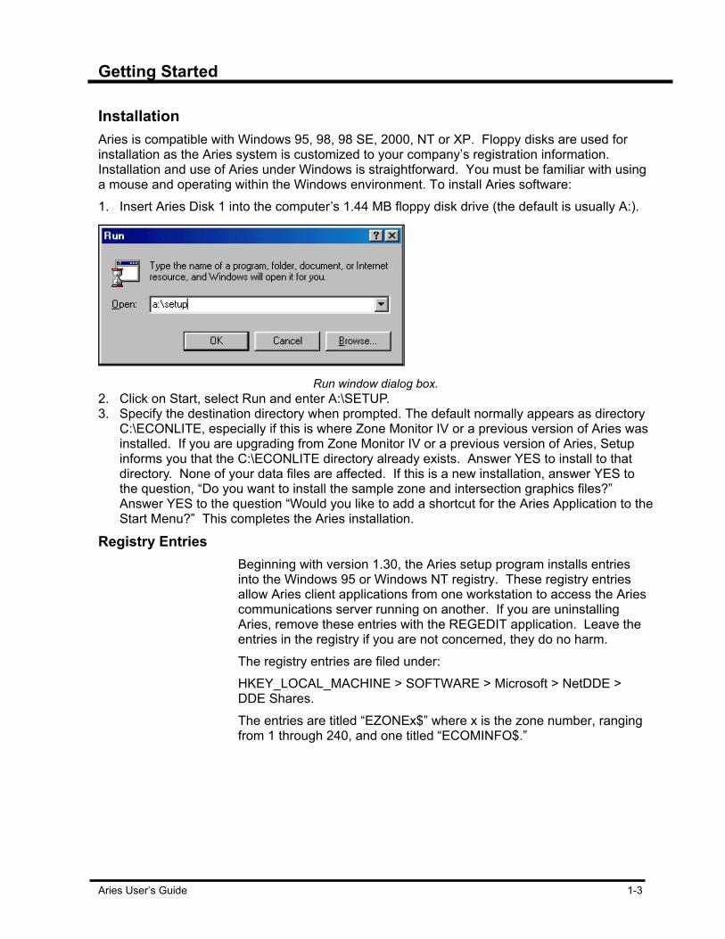
Installation Aries is compatible with Windows 95, 98, 98 SE, 2000, NT or XP. Floppy disks are used for installation as the Aries system is customized to your company’s registration information. Installation and use of Aries under Windows is straightforward. You must be familiar with using a mouse and operating within the Windows environment. To install Aries software: 1. Insert Aries Disk 1 into the computer’s 1.44 MB floppy disk drive (the default is usually A:).
Run window dialog box.
2. Click on Start, select Run and enter A:\SETUP. 3. Specify the destination directory when prompted. The default normally appears as directory
C:\ECONLITE, especially if this is where Zone Monitor IV or a previous version of Aries was installed. If you are upgrading from Zone Monitor IV or a previous version of Aries, Setup informs you that the C:\ECONLITE directory already exists. Answer YES to install to that directory. None of your data files are affected. If this is a new installation, answer YES to the question, “Do you want to install the sample zone and intersection graphics files?” Answer YES to the question “Would you like to add a shortcut for the Aries Application to the Start Menu?” This completes the Aries installation.
Registry Entries Beginning with version 1.30, the Aries setup program installs entries
into the Windows 95 or Windows NT registry. These registry entries allow Aries client applications from one workstation to access the Aries communications server running on another. If you are uninstalling Aries, remove these entries with the REGEDIT application. Leave the entries in the registry if you are not concerned, they do no harm. The registry entries are filed under: HKEY_LOCAL_MACHINE > SOFTWARE > Microsoft > NetDDE > DDE Shares. The entries are titled “EZONEx$” where x is the zone number, ranging from 1 through 240, and one titled “ECOMINFO$.”
Getting Started
1-4 Aries User’s Guide
Mixed Windows NT-2000-XP/95-98 Network Problems Due to security model inconsistencies between Windows 95-98 and
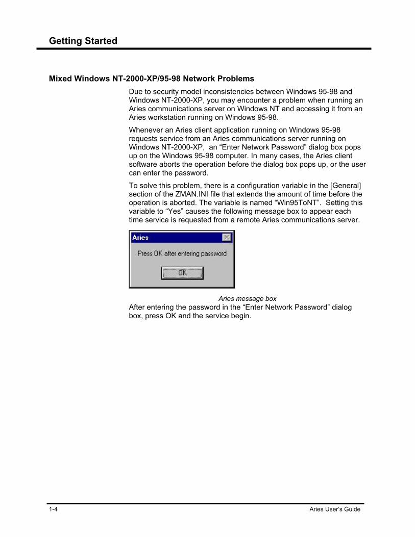
Windows NT-2000-XP, you may encounter a problem when running an Aries communications server on Windows NT and accessing it from an Aries workstation running on Windows 95-98. Whenever an Aries client application running on Windows 95-98 requests service from an Aries communications server running on Windows NT-2000-XP, an “Enter Network Password” dialog box pops up on the Windows 95-98 computer. In many cases, the Aries client software aborts the operation before the dialog box pops up, or the user can enter the password. To solve this problem, there is a configuration variable in the [General] section of the ZMAN.INI file that extends the amount of time before the operation is aborted. The variable is named “Win95ToNT”. Setting this variable to “Yes” causes the following message box to appear each time service is requested from a remote Aries communications server.
Aries message box
After entering the password in the “Enter Network Password” dialog box, press OK and the service begin.

Getting Started
Aries User’s Guide 1-5
Aries File/Comm. Server LAN Setup This procedure assumes that the LAN is already installed and
functional. To verify that the LAN status is functional, try playing a game of Hearts over the LAN using the Aries Communications Server computer and a workstation computer. If you can play Hearts, then the LAN is working. To function properly, File and Print Sharing must be installed on both the File/Communication (File/Comm.) Server(s) and the Workstation computer(s). If the IPX/SPX protocol is to be used over the LAN, then NETBIOS must also be enabled over IPX/SPX. NETBIOS is automatically enabled for TCP/IP and NETBUI when these protocols are installed. To install Aries on the File/Comm. Server computer: 1. Insert the first of the two, 3 ¼” floppy disks. 2. As the installation process proceeds, answer YES to the “INSTALL
SAMPLE ZONE AND INTERSECTION GRAPHICS DISPLAY?” question, to the “ADD ARIES COMMUNICATIONS SERVER TO THE STRAT-UP MENU?” question, and to the “ADD ARIES TO THE START MENU?” question. If Aries is running on a Windows NT, 2000, or XP platform, you must also run a program named ARIESNT.EXE.
3. If Aries is running on a Windows NT, 2000, or XP platform, you must also run a program named ARIESNT.EXE. a. Check that NDDE services are running. If not, set them to start
automatically and start them. b. Go to START > PROGRAMS > WINDOWS EXPLORER. c. Scroll the left windowpane to C:\ and expand the tree to locate
the ECONLITE folder and ARIES sub-folder. Left-click on the ARIES sub-folder in the left windowpane to open it.
d. Locate the ARIESNT.EXE program in the ARIES folder on the right windowpane and double-click on it to run the program.
To share access to the ECONLITE folder so that the workstation(s) may access the data files via the LAN: 1. Go to START > PROGRAMS > WINDOWS EXPLORER. 2. Scroll the left windowpane to C:\ and expand the tree if necessary
to locate the ECONLITE folder. 3. Left-click on the ECONLITE folder and then right-click on it to open
a pop-up menu. 4. Left-click on SHARING and the GENERAL TAB should have only
ARCHIVE checked. 5. Left-click on the SHARING TAB and left-click the radio button for
SHARED AS: 6. The share name should be ECONLITE and select ACCESS TYPE
= FULL. Note – DO NOT enter a Password!
Getting Started
1-6 Aries User’s Guide
7. Left-click on the APPLY button and left-click on the OK button. After a moment the “hand” symbol should appear on the ECONLITE folder in the left windowpane to indicate that it is shared.

Getting Started
Aries User’s Guide 1-7
To configure Aries for LAN: 1. Double-click on the ARIES folder in the right windowpane to open
the folder and locate the ZMAN.INI file in the ARIES folder. 2. Double-click on it to open it. If Windows asks what program to use
to open the file, select NOTEPAD. 3. Locate the [DIRECTORIES] section and add a line at the end of it
as follows: ShareProfile=C:\ECONLITE\ARIES\SHARE.INI
4. Locate the [GENERAL] section and change the Network=NO line to Network=YES. If the [GENERAL] section does not exist then it must be added to the ZMAN.INI file with the Network=YES line. For example:
[GENERAL] Network=YES 5. Save the changes just made to the ZMAN.INI file and close
NOTEPAD. 6. Create the SHARE.INI file on the File/Comm. Server.
Note – the SHARE.INI file tells Aries Zone Manager and the Aries File Server (generally the first Comm. Server is also the File Server) where to find the Comm. Server for each zone. For example, if there are 12 zones, then the SHARE.INI file will have 12 entries (one for each zone).
7. Go to START > PROGRAMS > ACCESSORIES > NOTEPAD. Based on the example in Step 6, create the file per the following example:
[ZONE1] SystemName=ARIES_COMM [ZONE2] SystemName=ARIES_COMM [ZONE3] SystemName=ARIES_COMM [ZONE4] SystemName=ARIES_COMM [ZONE5] SystemName=ARIES_COMM [ZONE6] SystemName=ARIES_COMM [ZONE7] SystemName=ARIES_COMM [ZONE8] SystemName=ARIES_COMM [ZONE9] SystemName=ARIES_COMM [ZONE10] SystemName=ARIES_COMM [ZONE11] SystemName=ARIES_COMM2 [ZONE12] SystemName=ARIES_COMM2
Getting Started
1-8 Aries User’s Guide
Note: ARIES_COMM and ARIES_COMM2 are the computer names as they appear on the network. These names may be anything. The actual names may be viewed by looking on the IDENTIFICATION tab of the NETWORK ICON on the CONTROL PANEL. Also note that Aries is limited to a maximum of 16 Comm. Channels per Comm. Server computer. This is why the computer name changed to ARIES_COMM2 in the example.
8. When finished entering the Zone assignments SAVE the file as SHARE.INI in the C:\ECONLITE\ARIES folder and close NOTEPAD. The File/Comm. Server is now setup for operation via a LAN. Close all programs and reboot the computer to start the LAN operation.
Configure Aries Workstation for LAN Setup. This procedure also assumes that the LAN is already installed and
functional. If there is any doubt about the LAN status try playing a game of Hearts over the LAN using the Aries Communications Server computer and the workstation computer. If you can play Hearts then the LAN should be working well enough for Aries. To install Aries on the workstation computer: 1. Answer NO to the Install Sample Zone and Intersection Display
question and NO to the Add Aries Comm. Server to the Start-up Menu question. Answer YES to the Add Aries to the Start Menu question. Note: This is a LAN installation so Aries Comm. Server must only run on the File/Comm. Server computer(s). Provide a means for Aries to access the files stored on the File/Comm. server by mapping a network drive to the File/Comm. Server.
2. Go to START > PROGRAMS > WINDOWS EXPLORER and left Click NETWORK NEIGHBORHOOD.
3. Keep expanding the tree until you can see the Comm. Server computer and double-click the Comm. Server computer.
4. Left-click on the ECONLITE folder and right-click on the folder. 5. Left-click on the MAP NETWORK DRIVE option. Make sure that
the RECONNECT AT LOGON box is checked. Note: The drive letter to be assigned (most likely this will be E: or F: although it can be set to any available letter).
6. Left-click on OK.
At this point, you must redirect Aries to the files stored on the File/Communications server computer and edit the ZMAN.INI file on the workstation computer to point to the File/Comm. Server files.
Getting Started
Aries User’s Guide 1-9
To redirect Aries to the File/Comm. Server files: 1. Go to START > PROGRAMS > WINDOWS EXPLORER. 2. Scroll to C:\ on the left windowpane and locate the ECONLITE
folder. Left-click the + box to expand the tree and left-click on the ARIES folder in the left windowpane.
3. Locate the ZMAN.INI file in the right windowpane and double-click on it. Select NOTEPAD when Windows asks what program to use to open the ZMAN.INI file.
4. Find the [DIRECTORIES] section and change it as follows: ZMDBASE=F:\ZMDBASE ZMLOGS=F:\ZMLOGS ZMGRAPHS=F:\ZMGRAPHS SYSEVENT=F:\SYSEVENT Where F: is the drive letter mapped to the File/Comm server in step #2 above.
5. Add a line in the [DIRECTORIES] section as follows: ShareProfile=F:\ARIES\SHARE.INI
6. Locate the [GENERAL] section and change the NETWORK=NO line to NETWORK=YES. If the [GENERAL] section does not exist then it must be added to the ZMAN.INI file with the NETWORK=YES line. For example: [GENERAL] Network=YES
7. Save the changes just made to the ZMAN.INI file and close NOTEPAD and Windows Explorer.
The Workstation is now setup to run Aries over the LAN connection.
Renaming Sysevent.rtf Messages in the system event window are stored in a file named
sysevent.rtf. Sysevent.rtf loads each time the Aries communications server is started. After some time, the file becomes quite large, and depending on the speed of the computer, it can take several minutes to start the Aries communications server. Renaming this file on a periodic basis prevents this problem. Next time the Aries communications server is activated, it creates a new sysevent.rtf file. The rich text format (.rtf) file is able to display with Wordpad which is included with Windows. Wordpad displays or prints all of the Aries system events. You must shut down the Aries Communications Server before opening sysevent.rtf with Wordpad. To rename the sysevent.rtf file: 1. Shut down the Aries Communications Server. 2. Start Windows Explorer from the start button. 3. Browse to C:\ECONLITE\SYSEVENT folder. 4. Select the sysevent.rtf file. 5. Right click on the filename and select “rename” from the popup
menu.

Getting Started
1-10 Aries User’s Guide
6. Type in the desired name. Be sure to include the .rtf on the end. 7. Press Enter. 8. Restart the Aries Communications Server.
Aries Configuration Variables Aries configuration information is stored in a text file named ZMAN.INI.
This file is located in the ARIES directory along with the Aries program files. If for any reason you want to specify a different file to be read for configuration, set an environment variable called in ZMAN in AUTOEXEC.BAT to point to the desired file. An example line to set the environment variable would be:
SET ZMAN=E:\STATION3\ARIES\CONFIG.INI
Configuration Variable Summary The following tables are summaries of the configuration variables in
ZMAN.INI. The ZMAN.INI file follows the standard windows INI file format. There are sections with the section headings in brackets [ ]. Each section has configuration variables followed by an equal sign, then the configuration variable assignment. Configuration variables and their assignments must be spelled exactly as shown; however, capitalization is ignored. A line in the file may be disabled by inserting a semicolon at the start of the line.
Configuration Variable Tables
Channel one section.
[Channel1] Channel one section. There are similar sections for each channel that is supported by the Aries computer hardware.
BitRate 300, 1200, 2400, 4800, 9600, 19200 or 38400 bits per second. Default is 2400. In case of direct-connect communications, this is the bit rate used. In case of modem communications, this is the initial bit rate, used to initialize the modem. .
CommType DIRECT or MODEM. Default is MODEM. Specifies if devices are connected directly to this channel or if dial-up modem communications are used.
ConnectDelay Amount of time Aries waits after the modem reports that it is connected, before sending any data. One unit is 100 milliseconds
DataBits 7 or 8. Default is 7. Number of data bits per frame. Set to 7.
Debug1 Yes or no. Default is no. Enables logging of port input/output to the debug window and debug file for this channel.
Getting Started
Aries User’s Guide 1-11
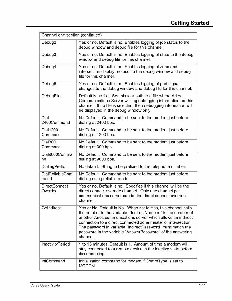
Channel one section (continued)
Debug2 Yes or no. Default is no. Enables logging of job status to the debug window and debug file for this channel.
Debug3 Yes or no. Default is no. Enables logging of state to the debug window and debug file for this channel.
Debug4 Yes or no. Default is no. Enables logging of zone and intersection display protocol to the debug window and debug file for this channel.
Debug5 Yes or no. Default is no. Enables logging of port signal changes to the debug window and debug file for this channel.
DebugFile Default is no file. Set this to a path to a file where Aries Communications Server will log debugging information for this channel. If no file is selected, then debugging information will be displayed in the debug window only.
Dial 2400Command
No Default. Command to be sent to the modem just before dialing at 2400 bps.
Dial1200 Command
No Default. Command to be sent to the modem just before dialing at 1200 bps.
Dial300 Command
No Default. Command to be sent to the modem just before dialing at 300 bps.
Dial9600Command
No Default. Command to be sent to the modem just before dialing at 9600 bps.
DialingPrefix No default. String to be prefixed to the telephone number.
DialReliableCommand
No Default. Command to be sent to the modem just before dialing using reliable mode.
DirectConnect Override
Yes or no. Default is no. Specifies if this channel will be the direct connect override channel. Only one channel per communications server can be the direct connect override channel.
GoIndirect Yes or No. Default is No. When set to Yes, this channel calls the number in the variable “IndirectNumber,” is the number of another Aries communications server which allows an indirect connection to a direct connected zone master or intersection. The password in variable “IndirectPassword” must match the password in the variable “AnswerPassword” of the answering channel.
InactivityPeriod 1 to 15 minutes. Default is 1. Amount of time a modem will stay connected to a remote device in the inactive state before disconnecting.
IniCommand Initialization command for modem if CommType is set to MODEM.

Getting Started
1-12 Aries User’s Guide
Channel one section (continued)
LockSpeed Yes or No. Default is No. Set to Yes if using a speed buffering modem and that feature is enabled.
Mode MonitorExclusive, CallExclusive or Any. Default is Any. Controls how this channel is allocated for client requests.
PagerCode No default. Numeric string to send after sending the PagerID and waiting the PagerPause2 time.
PagerID No default. Numeric string to send after connecting to numeric pager service.
PagerNumber No default. Telephone number of a numeric pager service to call when a priority one event occurs.
PagerPause1 Default is 0. Interval of time in tens of milliseconds to wait between sending the pager telephone number and sending the pager id number.
PagerPause2 Default is 0. Interval of time in tens of milliseconds to wait between sending the pager ID number and sending the pager code.
Parity Even, Odd or None. Default is E. Parity mode for this channel. Set to E.
Port 0 to 254. Enter the port number to use for the channel. Default is 0, which disables the channel.
StopBits 1 or 2. Default is 1. Number of stop bits per frame. Normally 1.
UseForZones ALL or a comma-separated list of zone numbers. Default is ALL. Determines what zones this channel connects with.
ZoneNumber Checking
Yes or No. Default is Yes. When Yes, if the master number in the controller does not match the requested zone number, the connection fails.
IndirectNumber Telephone number for indirect connection (see “GoIndirect”). The first character determines the bit rate for the connection. If it is a number from 0 to 9, the bit rate is 300. If it is a dollar sign ($), the bit rate is 1200. If it is a percent sign (%), the rate is 2400.
IndirectPassword A password used to attempt indirect connection (see “GoIndirect”).
AnswerPassword Password used to allow indirect connection through this channel (see “GoIndirect”).
Table 1-1: Channel one table
Getting Started
Aries User’s Guide 1-13
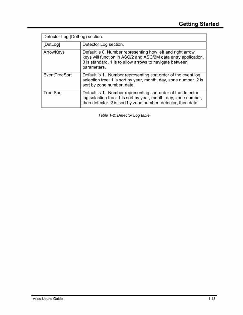
Detector Log (DetLog) section.
[DetLog] Detector Log section.
ArrowKeys Default is 0. Number representing how left and right arrow keys will function in ASC/2 and ASC/2M data entry application. 0 is standard. 1 is to allow arrows to navigate between parameters.
EventTreeSort Default is 1. Number representing sort order of the event log selection tree. 1 is sort by year, month, day, zone number. 2 is sort by zone number, date.
Tree Sort Default is 1. Number representing sort order of the detector log selection tree. 1 is sort by year, month, day, zone number, then detector. 2 is sort by zone number, detector, then date.
Table 1-2: Detector Log table

Getting Started
1-14 Aries User’s Guide
Directories section
[Directories] Directories section heading, indicating configuration variables relating to directories
BackupRestore Default is C:\ARIESBKP.ZIP. Path to file that the Aries Zone Manager will use for backup and restore operation.
MessageLogFileName
Default is no file. Set this to a path to a file where the Aries Communications Server will log all progress messages to Aries client programs. If no file is selected, then messages will not be logged.
ShareProfile Path to file with list of computer names for network communication servers. Not used if network is set to No. Default is .\SHARE.INI (SHARE.INI in the current directory.)
ScheduleFile Name
Default is ZMDBASE\ZMAN.SCH where ZMDBASE is defined by the ZMDBASE configuration variable. This path leads to the file where the Aries Operations Scheduler stores and reads its schedule.
ScheduleLogFileName
Default is ZMLOGS\SCHEDULE.LOG. Path to file where the Aries Operations Scheduler will store a log of all messages.
SYSEVENT Path to system event file. Default is C: \ECONLITE\SYSEVENT.
ZMDBASE Path to zone and intersection directories and controller files. Default is C:\ECONLITE\ZMDBASE. This path should be a valid MS DOS path in order for the ASC, KMC, KFT, and Intersection Monitor data entry functions to work. The path should start with a valid drive letter, such as ‘c:’, and each subdirectory separated with a single ‘\’. Each subdirectory name should be limited to eight characters. The path should not contain spaces.
ZMLOGS Path to log and event files. Default is C:\ECONLITE\ZMLOGS.
ZMGRAPHS Path to zone and intersection display graphics files. Default is C:\ECONLITE\ZMGRAPHS.
Table 1-3: Directories Table

Getting Started
Aries User’s Guide 1-15
General Configuration Table.
[General] General section heading, indicating non-specific configuration variables.
Maintenance Computer
Yes or No. Default is No. When an Aries workstation is configured as a “Maintenance Computer”, certain features are disabled to prevent fragmentation of log and event files. A “Maintenance Computer” cannot command a manual transfer of detector log or event files nor can it be used to schedule detector log or event transfers.
Network Yes or No. Default is No. Used to enable searching the network for communication servers.
Win95ToNT Yes or No. Default is No. Set to Yes when accessing a remote communications server on Windows NT-2000-XP from an Aries client running on Windows 95-98.
Table 1-4: General Configuration table
Monitor section.
[Monitor] Monitor section.
ImeventLikeZM Yes or No. Default is No. When Yes, Intersection Monitor events inserted in the system event file matches the Zone Master event format.
Priority1Alert YES or NO. Communications Server pops up a message box when events are received, if set to YES.
Table 1-5: Monitor section table
Schedule Configuration Table
[Schedule] The Aries operation scheduler stores its configuration variables in this section.
Columns The column widths for the operations scheduler set by the user are stored here.
Logging Yes or No. Default is Yes. Specifies if the file SCHEDULE.LOG is created.
Max Conversations
Default is 20. Maximum number of conversations the Aries Operations Scheduler will have at one time with the Aries Communications Server. If more operations are scheduled, they will be performed serially.
Getting Started
1-16 Aries User’s Guide
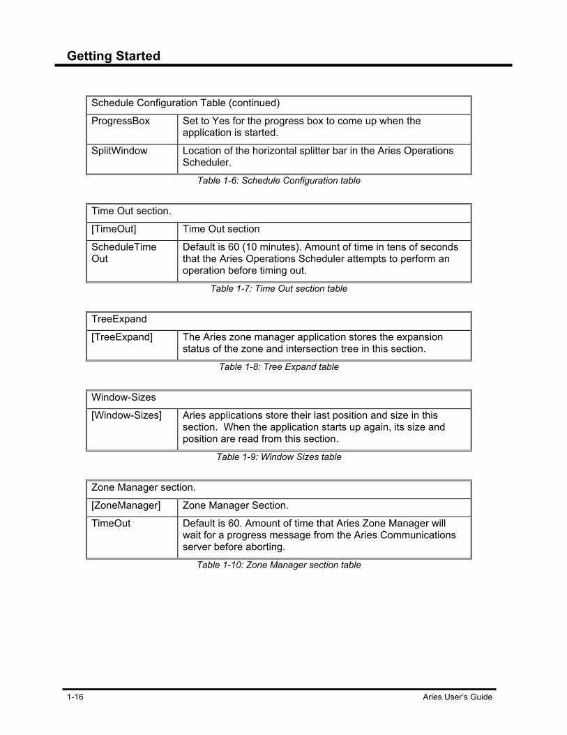
Schedule Configuration Table (continued)
ProgressBox Set to Yes for the progress box to come up when the application is started.
SplitWindow Location of the horizontal splitter bar in the Aries Operations Scheduler.
Table 1-6: Schedule Configuration table
Time Out section.
[TimeOut] Time Out section
ScheduleTime Out
Default is 60 (10 minutes). Amount of time in tens of seconds that the Aries Operations Scheduler attempts to perform an operation before timing out.
Table 1-7: Time Out section table
TreeExpand
[TreeExpand] The Aries zone manager application stores the expansion status of the zone and intersection tree in this section.
Table 1-8: Tree Expand table
Window-Sizes
[Window-Sizes] Aries applications store their last position and size in this section. When the application starts up again, its size and position are read from this section.
Table 1-9: Window Sizes table
Zone Manager section.
[ZoneManager] Zone Manager Section.
TimeOut Default is 60. Amount of time that Aries Zone Manager will wait for a progress message from the Aries Communications server before aborting.
Table 1-10: Zone Manager section table
Getting Started
Aries User’s Guide 1-17
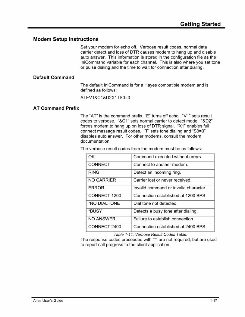
Modem Setup Instructions Set your modem for echo off. Verbose result codes, normal data
carrier detect and loss of DTR causes modem to hang up and disable auto answer. This information is stored in the configuration file as the IniCommand variable for each channel. This is also where you set tone or pulse dialing and the time to wait for connection after dialing.
Default Command The default IniCommand is for a Hayes compatible modem and is
defined as follows:
ATEV1&C1&D2X1TS0=0
AT Command Prefix The “AT” is the command prefix. “E” turns off echo. “V1” sets result
codes to verbose. “&C1” sets normal carrier to detect mode. “&D2” forces modem to hang up on loss of DTR signal. “X1” enables full connect message result codes. “T” sets tone dialing and “S0=0” disables auto answer. For other modems, consult the modem documentation. The verbose result codes from the modem must be as follows:
OK Command executed without errors.
CONNECT Connect to another modem.
RING Detect an incoming ring.
NO CARRIER Carrier lost or never received.
ERROR Invalid command or invalid character.
CONNECT 1200 Connection established at 1200 BPS.
*NO DIALTONE Dial tone not detected.
*BUSY Detects a busy tone after dialing.
NO ANSWER Failure to establish connection.
CONNECT 2400 Connection established at 2400 BPS.
Table 1-11: Verbose Result Codes Table. The response codes proceeded with “*” are not required, but are used to report call progress to the client application.


Aries User’s Guide 2-1
Chapter 2 Aries Introduction Aries® is the Microsoft® Windows® based data management and monitoring system for the Econolite traffic control equipment. It offers many capabilities not offered by Econolite’s DOS based Zone Monitor IV system. A 32-bit application, Aries utilizes the capabilities of Windows 95, 98, 98SE, NT, 2000, and XP.
Aries Window This section provides a basic reference to the Aries window. The Aries system applications share basic screen features. All application screens have a File, Launch and About Menu. File Menus contain basic functions for the application. Most applications have a second Menu feature, the name changes depending on the application. In the picture below, it is called the Access Menu. The Launch Menu contains links to the other Aries applications, while the About Menu shows the current registration and release of the application.
Aries Zone Manager screen showing the Launch Menu
In the picture above, the Aries Zone Manger shows one full screen. Be aware this does not apply to all the applications. Several have split screens, some split vertically, some split horizontally, while one application has the ability to have many screens tile or cascade in it, another one shows three screens within its window.
Menu bar
Toolbar Buttons
Status bar
Launch Menu
Title bar

Aries Introduction
2-2 Aries User’s Guide
General Application Features Every Aries application has a File menu with menu commands differing
according to the application. Each application has a Launch Menu, which lists other applications available to open. This menu looks similar in all the Aries applications, except the name of the active application is not included in this list. These same items are repeated as buttons in the tool bar. The About Menu shows the Aries application name, the version of the installed Aries system, copyright information, Econolite Control Products is listed as the manufacturer, and the person and company the software is registered to. Toolbar buttons vary from application to application. Command buttons appear on the left hand side of the bar and application buttons are located on the right. The names of the Toolbar buttons appear as you move the mouse over them. Aries makes use of right-click pop-up menus. Highlighting a node and right-clicking on it, brings up a pop-up menu. The commands listed in this menu box, enable you to perform many tasks. In the Aries Zone Manager, the toolbar contains many buttons, as the Zone Manger has many commands that apply differently to zones master controllers, intersection controllers and intersection monitors. Be aware that the right-click menus are more complex when using Zone Manager, as they deal with zone, intersections and intersection monitors. A Supervisor or Data Change access code is necessary to unlock the system application before using the application itself or instigate an action, such as an upload or change information through the data entry screens. If the system remains locked, you must enter the Supervisor or Data Change access code to perform the command selected
Graphical User Interface The Aries menu tree allows point-and-click selection of zones,
intersections and functions. The pull-down menus and dialog boxes provide information on demand. Multiple windows can open simultaneously, to include real-time zone map and intersection displays. Icons simplify user interface. Icons change as events status changes, while toolbars allow quick selection of commonly used functions via tool tips that identify each icon.
Multiple Communication Ports Activate up to 16 communication ports simultaneously per communica-
tion server. Windows 95, 98, 98SE, NT, 2001, and XP, support COM port addresses 1-254. With available telephone and modem lines, these COM ports allow simultaneous communications up to 16 zones.

Aries Introduction
Aries User’s Guide 2-3
Multitasking Operations Check system operations while database management and other tasks
are being performed. Run system monitor tasks and event scheduling tasks in background while other tasks are running in foreground, including applications other than Aries. Multitasking operation scheduler allows multiple operations to be scheduled for the same time. Program operations to repeat at intervals specified in minutes, hours, days, months or years.
Client Server Model Windows 95, 98, 98SE, NT, 2000 and XP operation of Aries is based
on a client server model. ARIESCOM.EXE is the server. The client application requests data from the server. If the server is able to connect to an Econolite controller device and obtain the data, it sends data to the client for processing. The client server model opens the opportunity of a distributed version of Aries, allowing the server to run on one computer and the client applications, to run on one or more other computers. To perform a specific function, simply click on the respective client application.
Distributed Network Support The communication server handles all communication tasks. It runs as
a task on the main workstation or is located on a separate PC. Perform system operations from any workstation. The indirect connection feature allows a remote Aries computer to access zone masters or controllers directly connected to an Aries communications server.
Database Management Functions Upload, edit, download and compare ASC/2M and KMC-10,000 Zone
Master files. Allows uploads, edits, downloads and comparison of ASC/2, ASC-8000, KMC, KFT and Intersection Monitor files. Editing of KMC-10,000 Zone Master, ASC-8000, KMC, KFT and Intersection Monitor files are supported by Aries using DOS tasks. Zone-Intersection notes feature allows recording history of changes to database or other actions. Summary displays of TOD, NIC and coordination patterns allow easy review of coordination programming.
Monitor Mode Receives alarms and events from ASC/2M Zone Master, KMC-10,000
Zone Masters and Intersection Monitor II. Allows detector log transfers. Run as a task in background. Separate windows for event and status reports.

Aries Introduction
2-4 Aries User’s Guide
Operation Scheduler Scheduler allows operations to be initiated automatically by time of day.
Multitasking capability allows multiple operations to be scheduled for the same time. Operations are completed as the communications server is available to provide service. Operations are programmed in Operations Scheduler to repeat at intervals specified in minutes, hours, days, months or years. Icons in Operations Scheduler indicate status of scheduled operations. Separate windows for Operation Scheduler tasks and status allow quick determination of the operation.
Manual Commands Allows the following operations to be initiated manually from Aries
computer:
• Status report. • Event report for ASC/2M and KMC-10,000. • Detector log transfer for ASC/2M and KMC-10,000. • Event, detector and MMU event transfer for ASC/2
controller. • Display and change intersection commanded Free status. • Display and change intersection commanded Flash status.
Printing/Plotting/Exporting Features
Detector log data is presented in table or plot format, with instant switching between tables and plots for easy viewing. This feature has the ability to drag and drop additional detectors or the summation of multiple detectors, into tables and plots, thus generating multiple-detector presentations. Export detector files for analysis by external programs, such as Excel or MathCAD. Filter alarm and event data to create custom reports from Zone Master or ASC/2 event files. Create event or log report profiles for quick retrieval of previously created reports or graphs.
Split Monitor Report Split monitor reports display split utilization. Data is accumulated from
multiple intersections simultaneously and printed and/or saved to text files. Programmable start times and duration when commanded from Operations Scheduler for unattended operation.
Aries Introduction
Aries User’s Guide 2-5
Graphic Displays Graphics display in multiple open windows, showing real-time Zone
Map Displays or Intersection Displays from different zones. Intersection displays are launched from Zone Map Display by double-clicking on specific intersections. The Fit to window feature allows graphic windows to be resized without cropping. Intersection dialog boxes are shown in real-time with alphanumeric data on demand. This allows cleaner and easier-to-generate intersection displays. Alphanumeric captions may be added to displays at the option of the user. The user has a choice of 16, 256 or 65,536 colors. PCX graphic files of any size are used to create Zone Map Displays and Intersection Displays.
Data File Compatibility with Zone Monitor IV Aries data files are downward compatible with Zone Monitor IV with the
following exceptions: The Zone Monitor IV print buffer file is replaced by SYSEVENT.RTF in Aries. Intersection and Zone display files generated by Aries are compatible with Zone Monitor IV only if the original PCX image files used to generate them were Zone Monitor IV compatible. Operations Scheduler files are not compatible with Zone Monitor IV.
Operation with Zone Monitor IV To run Zone Monitor IV and Aries at the same time, you must use a
separate communication port and modem for each. Zone Monitor IV is a DOS application and is not fully guaranteed to run under the Windows multitasking environment and Aries is a Windows-based application. Do not run any Zone Monitor IV High-Res graphics features (intersection display, zone display or green band display) under Windows. Do not run the Zone Monitor IV monitor mode and Aries monitor at the same time. If you are running the network version of Zone Monitor IV, setting it up as a maintenance workstation prevents it from entering the monitor mode.
Chapters 3 - 10 are intended as tutorials chapters for getting started with Aries. Once these tutorials are finished, you may find Aries to be intuitive enough to operate without further reading. Chapters 11 – 23 contain narratives of each Aries application.

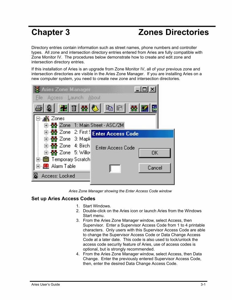
Aries User’s Guide 3-1
Chapter 3 Zones Directories Directory entries contain information such as street names, phone numbers and controller types. All zone and intersection directory entries entered from Aries are fully compatible with Zone Monitor IV. The procedures below demonstrate how to create and edit zone and intersection directory entries. If this installation of Aries is an upgrade from Zone Monitor IV, all of your previous zone and intersection directories are visible in the Aries Zone Manager. If you are installing Aries on a new computer system, you need to create new zone and intersection directories.
Aries Zone Manager showing the Enter Access Code window
Set up Aries Access Codes 1. Start Windows.
2. Double-click on the Aries icon or launch Aries from the Windows Start menu.
3. From the Aries Zone Manager window, select Access, then Supervisor. Enter a Supervisor Access Code from 1 to 4 printable characters. Only users with this Supervisor Access Code are able to change the Supervisor Access Code or Data Change Access Code at a later date. This code is also used to lock/unlock the access code security feature of Aries, use of access codes is optional, but is strongly recommended.
4. From the Aries Zone Manager window, select Access, then Data Change. Enter the previously entered Supervisor Access Code, then, enter the desired Data Change Access Code.
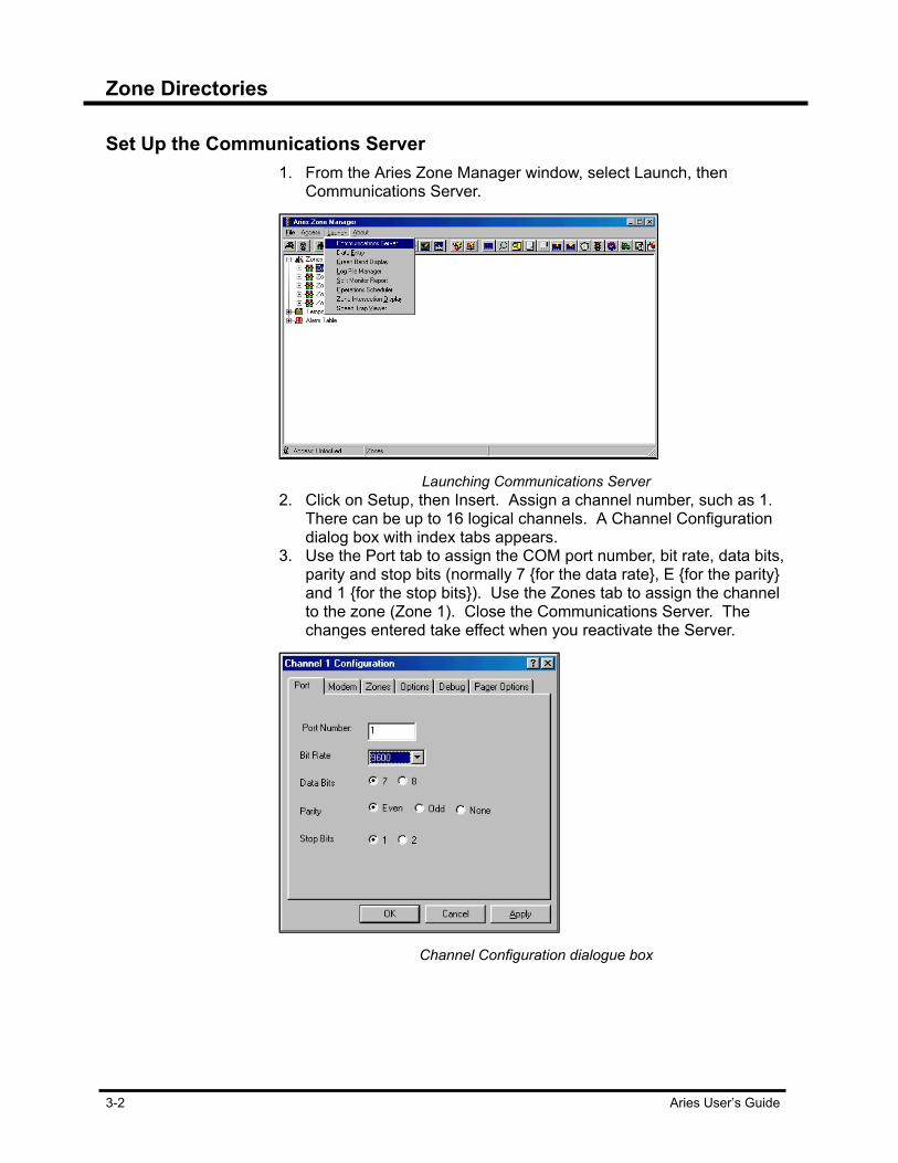
Zone Directories
3-2 Aries User’s Guide
Set Up the Communications Server 1. From the Aries Zone Manager window, select Launch, then
Communications Server.
Launching Communications Server
2. Click on Setup, then Insert. Assign a channel number, such as 1. There can be up to 16 logical channels. A Channel Configuration dialog box with index tabs appears.
3. Use the Port tab to assign the COM port number, bit rate, data bits, parity and stop bits (normally 7 {for the data rate}, E {for the parity} and 1 {for the stop bits}). Use the Zones tab to assign the channel to the zone (Zone 1). Close the Communications Server. The changes entered take effect when you reactivate the Server.
Channel Configuration dialogue box
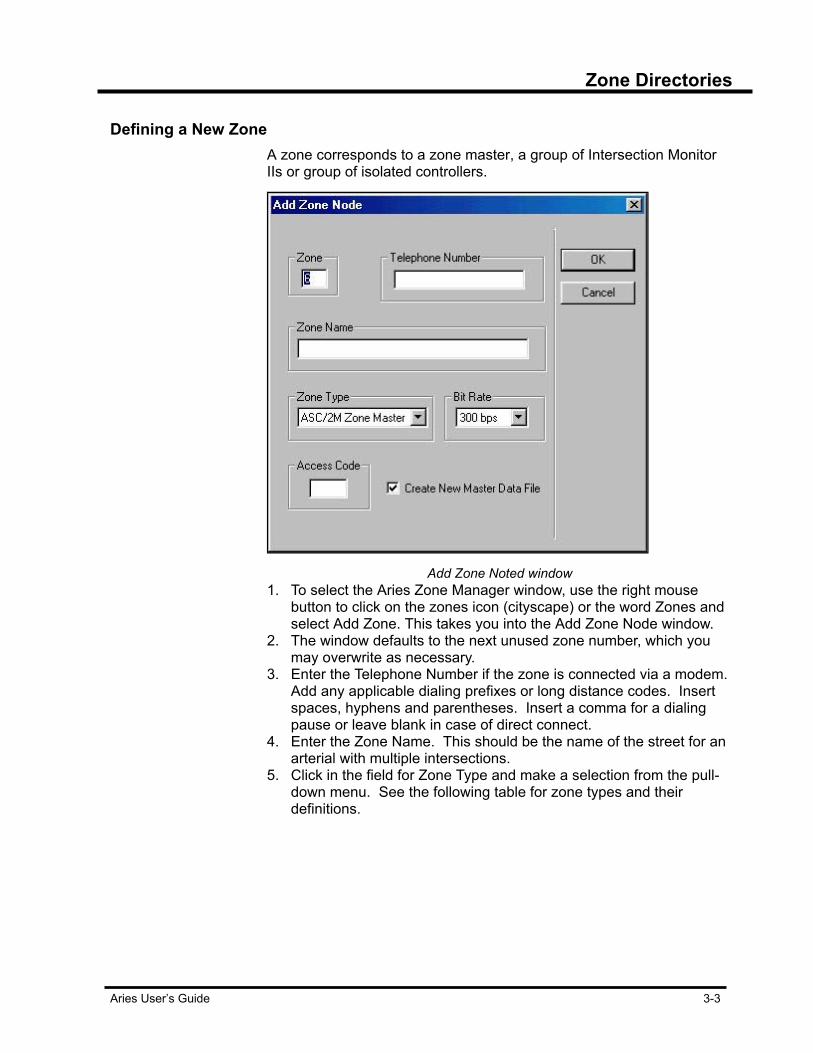
Zone Directories
Aries User’s Guide 3-3
Defining a New Zone A zone corresponds to a zone master, a group of Intersection Monitor
IIs or group of isolated controllers.
Add Zone Noted window
1. To select the Aries Zone Manager window, use the right mouse button to click on the zones icon (cityscape) or the word Zones and select Add Zone. This takes you into the Add Zone Node window.
2. The window defaults to the next unused zone number, which you may overwrite as necessary.
3. Enter the Telephone Number if the zone is connected via a modem. Add any applicable dialing prefixes or long distance codes. Insert spaces, hyphens and parentheses. Insert a comma for a dialing pause or leave blank in case of direct connect.
4. Enter the Zone Name. This should be the name of the street for an arterial with multiple intersections.
5. Click in the field for Zone Type and make a selection from the pull-down menu. See the following table for zone types and their definitions.

Zone Directories
3-4 Aries User’s Guide
Zone Type Definition
KMC Zone A zone with up to 24 controllers, where the KMC master runs firmware older than Zone Master III or IV firmware.
Intersection Monitor (IM) Zone
A zone with up to 24 controllers, each of which is being monitored by an Intersection Monitor II.
Zone Master III/IV A zone with up to 24 controllers, where a KMC-10,000 Zone Master runs Zone Master III or IV firmware.
ASC-ASC/2 Direct A zone of up to 24 isolated ASC-8000 or ASC/2 controllers with their own modem interface.
ASC/2M Zone Master A zone with up to 24 controllers, where an ASC/2M is the Zone Master.
3-1: Zone Type Definition Table
6. Click on the field for Bit Rate and make a selection from the pull-down menu. The normal choice should be 2400 bps. Use 1200 bps or 300 bps for older, slower modems in the field. This does not apply to Intersection Monitor II, ASC-8000 or ASC/2 direct zones.
7. Enter the Access Code for any Zone Master where an access code is required for security purposes. This code has been entered manually into the master or controller to prevent unauthorized program modification.
8. Check the box Create New Master Data File. This creates a data file for that zone on the Aries computer.
9. Click on OK. The Data Rate Selection window appears. Enter the same bit rate as entered previously, typically 2400 or 1200 bps.
10. Click on OK to complete data entry for the first zone.
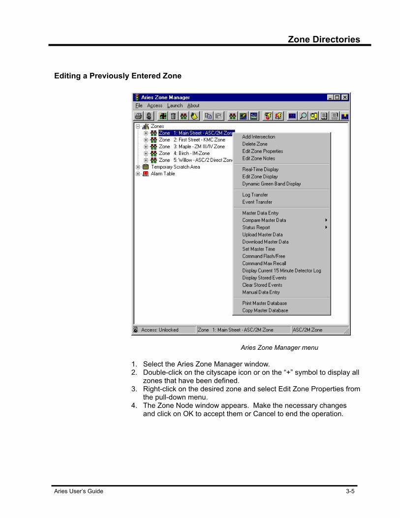
Zone Directories
Aries User’s Guide 3-5
Editing a Previously Entered Zone
Aries Zone Manager menu
1. Select the Aries Zone Manager window. 2. Double-click on the cityscape icon or on the “+” symbol to display all
zones that have been defined. 3. Right-click on the desired zone and select Edit Zone Properties from
the pull-down menu. 4. The Zone Node window appears. Make the necessary changes
and click on OK to accept them or Cancel to end the operation.

Zone Directories
3-6 Aries User’s Guide
Setting Zone Time To set the time for the Zone that you have defined:
1. In the Aries Zone Manager window, right-click on the zone.
Zone time set to computer time
2. Select Set Master Time. A window entitled Operation Progress
Messages appears. 3. Press Start to begin the operation. The time for the Zone is set to
the time of the computer when the message **** Operation Complete **** is displayed. Automatic time setting is covered later in this manual.
Activate the Communications Server Task When using Aries, keep the Communications Server running as a
Windows task, as shown in the Windows Task List or Task Bar. The Aries Setup program puts a program icon for the Communications Server in the Windows Startup Group, causing the Server to be activated each time Windows is started. If the Server has been deactivated, you must reactivate it: 1. Select the Aries Zone Manager Window and select Launch. 2. Select Communications Server. Wait several seconds until the
Aries Communications Server window comes up.

Zone Directories
Aries User’s Guide 3-7
Master Data Master data is stored in the controller’s memory. Master data is
changed either by manually entering in new information or by uploading the information, changing it and downloading it back to the controller.
Uploading Master Data Uploading master data allows the programmed information in the
controller to be accessed by the Aries system. There are three choices with an upload. They are Save, Compare or Cancel. Saving an upload saves this information as the new master data. This is good if the intersection controller is new and is being added to the system. Compare allows you to compare the uploaded data to the saved master data file Aries has stored. Canceling an upload stops the upload and does not save the data. 1. In the Aries Zone Manager window, right-click on the desired zone. 2. Select Upload Master Data and press Start to begin the operation.
The message ‘Upload Complete. SAVE, COMPARE OR CANCEL appears.
3. Select Save if this was your first upload to save the 2-kilobyte file on disk. The Compare option allows you to compare the uploaded data with data from a previously saved master data file for that zone. Cancel ends the operation.
Aries Data Entry Window Aries Data Entry window allows you to view and compare zone or
intersection database information to master database information. The window is made up of several sections. On the left is the Topic list. The items found there will vary depending on whether the database has been uploaded from a zone master or intersection controller. To the right are several tabs. The information displayed on these tabs will also vary depending not only on whether the database has been uploaded from a zone master or intersection controller, but what type of zone and/or intersection controller as well.
Be aware! Saving uploads overwrites previously saved master data files.

Zone Directories
3-8 Aries User’s Guide
Aries Data Entry window
Editing Master Data To edit the master data that you have uploaded:
1. In the Aries Zone Manager window, right-click on the zone. 2. Select Launch from the Menu bar and select Data Entry. 3. Enter the Data Entry access code, defined earlier, to prevent
unauthorized data modification. The Aries Data Entry for Zone window appears.
3. Make a minor data change (change it back later). 4. Save the data and close the window.
Comparing Master Data To compare the master data in the computer and in the equipment in
the field: 1. From the Aries Zone Manager window, right-click on the zone. 2. Select Compare Master Data, then Parameter Compare. 3. In the Operation Progress Messages window, click the Start button.
The Aries system compares the disk file to the uploaded file. 4. The Aries Data Entry for Zone window appears and shows any
discrepancy in two one-line fields at the bottom. Use the Back and Next buttons of the window to cycle between multiple discrepancy messages.
Downloading Master Data To download the edited master data:
1. In the Aries Zone Manager window, right-click on the zone. 2. Select Download Master Data and press Start to begin the
operation. The master download operation is completed when the message ‘**** Operation Complete ****’ appears.
3. Close the window. A compare operation at this time shows the disk files and the field files match. Be sure to undo any changes made from this exercise, by editing the disk file back to the correct version and downloading it.
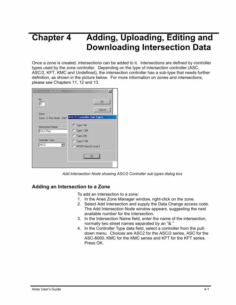
Aries User’s Guide 4-1
Chapter 4 Adding, Uploading, Editing and Downloading Intersection Data
Once a zone is created, intersections can be added to it. Intersections are defined by controller types used by the zone controller. Depending on the type of intersection controller (ASC, ASC/2, KFT, KMC and Undefined), the intersection controller has a sub-type that needs further definition, as shown in the picture below. For more information on zones and intersections, please see Chapters 11, 12 and 13.
Add Intersection Node showing ASC/2 Controller sub types dialog box
Adding an Intersection to a Zone To add an intersection to a zone:
1. In the Aries Zone Manager window, right-click on the zone. 2. Select Add Intersection and supply the Data Change access code.
The Add Intersection Node window appears, suggesting the next available number for the intersection.
3. In the Intersection Name field, enter the name of the intersection, normally two street names separated by an “&.”
4. In the Controller Type data field, select a controller from the pull-down menu. Choices are ASC2 for the ASC/2 series, ASC for the ASC-8000, KMC for the KMC series and KFT for the KFT series. Press OK.
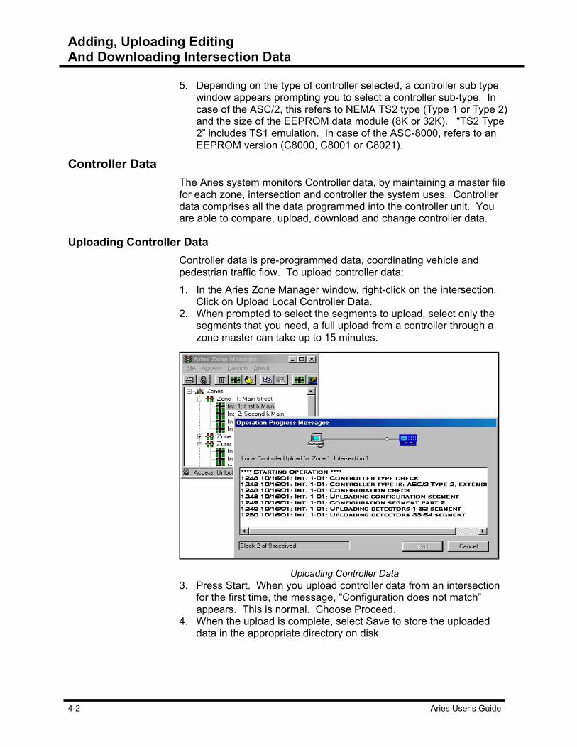
Adding, Uploading Editing And Downloading Intersection Data
4-2 Aries User’s Guide
5. Depending on the type of controller selected, a controller sub type window appears prompting you to select a controller sub-type. In case of the ASC/2, this refers to NEMA TS2 type (Type 1 or Type 2) and the size of the EEPROM data module (8K or 32K). “TS2 Type 2” includes TS1 emulation. In case of the ASC-8000, refers to an EEPROM version (C8000, C8001 or C8021).
Controller Data The Aries system monitors Controller data, by maintaining a master file
for each zone, intersection and controller the system uses. Controller data comprises all the data programmed into the controller unit. You are able to compare, upload, download and change controller data.
Uploading Controller Data Controller data is pre-programmed data, coordinating vehicle and
pedestrian traffic flow. To upload controller data: 1. In the Aries Zone Manager window, right-click on the intersection.
Click on Upload Local Controller Data. 2. When prompted to select the segments to upload, select only the
segments that you need, a full upload from a controller through a zone master can take up to 15 minutes.
Uploading Controller Data
3. Press Start. When you upload controller data from an intersection for the first time, the message, “Configuration does not match” appears. This is normal. Choose Proceed.
4. When the upload is complete, select Save to store the uploaded data in the appropriate directory on disk.

Adding, Uploading Editing And Downloading Intersection Data
Aries User’s Guide 4-3
Time out period Time out period refers to the amount of time before an upload or
connection is lost. The time out period is set at five minutes. After an upload is initiated, a ‘Compare, Save or Cancel’ message appears in the Operation Progress Message window. This message informs you that the options of Comparing the database information, Saving the information or Canceling the information. If a choice is not made within 5 minutes of this message’s appearance, the system times out and the information (upload) is lost. The connection idles for a time (from 1 – 15 minutes), then disconnects itself if the line is not engaged. This time frame is established when the communications channel is set in the Inactivity Field located on the Options tab.
Editing ASC/2 Controller Data To edit ASC/2 controller data:
1. In the Aries Zone Manager window, right-click on the intersection and click on Controller Data Entry. Enter the Data Entry Access Code.
Controller Data Entry window
Adding, Uploading Editing And Downloading Intersection Data
4-4 Aries User’s Guide
2. The Aries Data Entry screen appears. On the left hand side of the screen, there is a topic selection index. Clicking on each topic presents you with a different data entry sub-screens, located to the right of the index. The index tabs reflect other information topics to choose from, depending on the topic selected.
3. Make a minor change. For instance, select By Phase Timing Data and Min Timing. Change a Minimum Green Interval by 1 second. Click on Save under the File pull-down menu.
Editing ASC/2 and 2M data without committing to a file The Aries Data Entry screen allows you to edit files without overwriting
the controller file. ASC/2 and 2M database files. To edit these files: 1. In the Aries Data Entry window, click on the File and select Load
Data File. Select the Zone and Intersection of the information you want to edit and click on OK. The information from the database appears in the tabs in the right side of the screen. The tab’s appearance changes depending on the type of database controller.
2. Make the changes in the fields you want. Select File and Download Data File.
3. At the appearance of the Operation Progress Message window, click the Start button to begin the download process.
4. Once the process is complete, press the Close button to exit the Operation Progress Message window.
5. You have the choice of Loading another file, Closing out of this file or Saving the file with the changes you’ve made as the new Master file.
Editing ASC-8000 Controller Data To edit ASC-8000 controller data:
1. In the Aries Zone Manager window, right-click on the intersection and click on Controller Data Entry.
2. Enter the Data Entry Access Code. In case of the ASC-8000, this opens a DOS application which has been transferred from Zone Monitor IV. It does not respond to the mouse, only the keyboard. Caps Lock must be turned on otherwise, the Escape, Pg Up and Pg Down keys not work.
3. Make a minor data change. For instance, select 1. (Controller Data, Timing) and change Minimum Green by 1 second. Press Escape and F2 to save the change to file.
4. Press F1 to quit editing. 5. When exiting this application on Windows 95, an empty window with
the word “Finished” in the title bar is left on screen. Click the “X” button in the upper right hand corner to close the window.

Adding, Uploading Editing And Downloading Intersection Data
Aries User’s Guide 4-5
To close the window: 1. Run the desired data entry application from Zone Manager. 2. Click on the icon at the left of the title bar to show a menu. 3. Choose “Properties” from the menu. 4. Check the “Close on exit” check box and click OK.
Compare ASC/2 Controller Data To compare ASC/2 file and controller data:
1. In the Aries Zone Manager window, right-click on the intersection and click on Compare Local Controller Data. There are three options to choose from:
• Byte Compare provides pass/fail indication by segment (or topic) by comparing the data one byte at a time.
• Quick Compare also provides pass/fail indication by segment, but in much less time by limiting the comparison to 16-bit CRC results.
• Parameter Compare identifies the specific elements that differ.
Comparing ASC/2 controller data
2. Select Parameter Compare. Select the segments to be compared. Selecting fewer segments saves time. Press Start to begin the upload of data from the ASC/2 controller.
3. At the Aries Data Entry screen, the two fields at the bottom of the screen list any differences between the uploaded controller data and file data. Click on Next to move to the next difference. Click on Back to return to the previous difference.
4. Make any database changes using the Aries Data Entry screen. Select Save under the File pull-down menu to save any changes to disk. Begin a download operation to enter the file data into the ASC/2 controller.

Adding, Uploading Editing And Downloading Intersection Data
4-6 Aries User’s Guide
Comparing ASC-8000 Controller Data To compare databases on disk and in an ASC-8000 controller:
ASC/2 Upload/download Segments window with options selected.
1. In the Aries Zone Manager window, right-click on the intersection, select Compare Local Controller Data, then Parameter Compare. The latter identifies any parameters that are different. The other choice, Byte Compare, simply provides pass/fail information.
2. Press Start to upload data from the controller. Supply the Data Entry Access Code to initiate the actual compare operation.
3. A DOS-based Zone Monitor IV screen appears, showing the first parameter that has changed. Pressing the right arrow key repeatedly moves to the next changed parameters and finally terminates the compare operation.
Downloading Controller Data To download controller data:
1. In the Aries Zone Manager window, right-click on the intersection and click on Download Local Controller Data. A dialog box appears, allowing you to choose the segments to be downloaded.
2. Choose either all the segments or certain ones to download. Selecting only the segments you need to download, speeds up the download process and saves time.
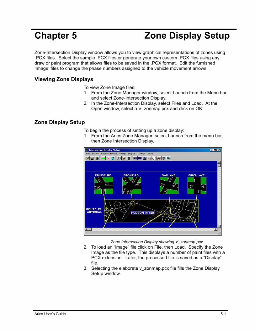
Aries User’s Guide 5-1
Chapter 5 Zone Display Setup Zone-Intersection Display window allows you to view graphical representations of zones using .PCX files. Select the sample .PCX files or generate your own custom .PCX files using any draw or paint program that allows files to be saved in the .PCX format. Edit the furnished ‘Image’ files to change the phase numbers assigned to the vehicle movement arrows.
Viewing Zone Displays To view Zone Image files:
1. From the Zone Manager window, select Launch from the Menu bar and select Zone-Intersection Display.
2. In the Zone-Intersection Display, select Files and Load. At the Open window, select a V_zonmap.pcx and click on OK.
Zone Display Setup To begin the process of setting up a zone display:
1. From the Aries Zone Manager, select Launch from the menu bar, then Zone Intersection Display.
Zone Intersection Display showing V_zonmap.pcx
2. To load an “image” file click on File, then Load. Specify the Zone Image as the file type. This displays a number of paint files with a PCX extension. Later, the processed file is saved as a “Display” file.
3. Selecting the elaborate v_zonmap.pcx file fills the Zone Display Setup window.
Zone Display Setup
5-2 Aries User’s Guide
Defining Vehicle Movements To define vehicle movements in the Zone Display Setup window:
1. Select Define, then Vehicle. The pointer changes to cross hairs. 2. Position the center of the cross hairs over a solid-colored area,
namely an arrow that signifies vehicle movement and click on the arrow. The arrow turns red to show that it has been selected and a dialog box appears, allowing you to assign a phase to the arrow. For example, assign Phase 3 to the arrow labeled 3. You also have to specify the number of the controller at that intersection, since there are many intersections in a zone display. The number to be entered is the number of the intersection as shown in the Aries Zone Manager window. The arrow then turns blue.
Modify Vehicle Movements To change a previously assigned vehicle movement:
1. Select Examine/Modify on the menu bar. The pointer changes to cross hairs.
2. Position the center of the cross hairs over the arrow for the movement to change and click on the arrow. The arrow turns red to show it has been selected and the required dialog box appears.
Saving Zone Displays To save the PCX file as a zone display:
1. When you are done editing, select Stop, File, then SaveDisplay. 2. When the selection tree appears, assign the file to the appropriate
zone.
Zone Display Setup
Aries User’s Guide 5-3
Viewing Live Zone Displays To view a live picture of the zone that has just been saved:
1. Select the Aries Zone Manager window, click on Launch on the menu bar, then on Zone-Intersection Display. The Aries Zone and Intersection Display window appears.
2. Select Display, specify the zone and click on OK. The saved display file loads onto the screen. The computer calls the zone master for real-time information. Be sure that the Communications Server is active.
3. A window with the Zone Display appears. Scroll bars on the edge of the window allow the field of view to be moved if the original image is larger than the window.
4. As an alternative to scrolling, select View and Fit to Window. The image is scaled to fill the window, without any cropping.
5. A defined and saved zone display is started from the Zone Manager by right clicking the corresponding zone and selecting the “Real-Time Display” menu item from the context menu.
Have Only One Active Task Per Zone Aries allows only one active task per zone. For example, setting the
time and date for the zone master while the Zone Display is open, is considered an active task. 1. In the Aries Zone Manager window, right-click on the zone. 2. Select Set Controller Time. This operation fails, demonstrating that
only one task is active for a zone at a time. 3. Stop the Zone Display by pressing Stop on the menu bar and the
Set Controller Time Set operation succeeds.


Aries User’s Guide 6-1
Chapter 6 Intersection Display Setup Intersection displays allow you to produce computer generated, graphic representations of intersections. With a variety of .pcx graphics, located in the Zmgraphs file, choose from many types of intersection scenarios. Use the display that best represents a specific intersection. Create and set detectors, monitor vehicle movements and view intersection traffic information in real-time among a variety of items to set on the display.
Starting Intersection Display
Starting Intersection Displays To start an intersection display:
1. Click on Display. The Zone Intersection Selection window appears. 2. Select the zone and intersection and click on OK. The Aries
computer contacts the intersection to retrieve real-time data. Or start from the Aries Zone Manager window: 1. Select the zone and intersection and right-click on the intersection. 2. Click on Real-Time Display. The correct street names are shown in
the real-time Intersection Display and that the colors red, yellow and green are shown for the phase arrows. An alarm box appears whenever there is a change in an alarm status.
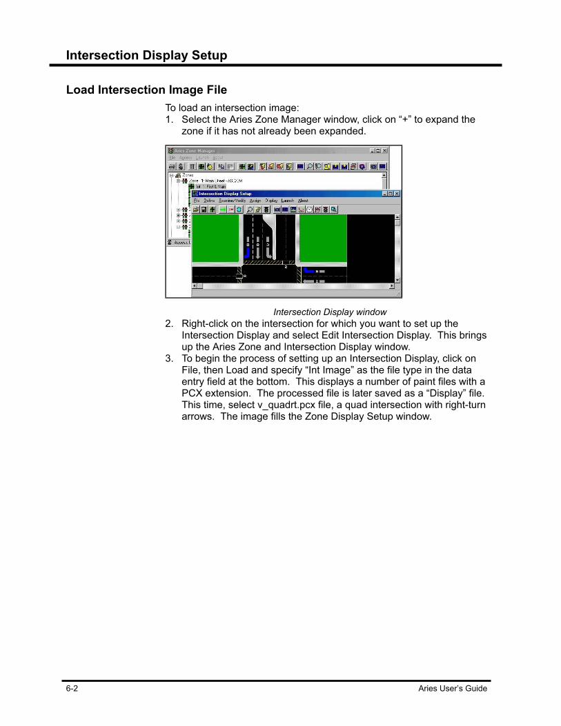
Intersection Display Setup
6-2 Aries User’s Guide
Load Intersection Image File To load an intersection image:
1. Select the Aries Zone Manager window, click on “+” to expand the zone if it has not already been expanded.
Intersection Display window
2. Right-click on the intersection for which you want to set up the Intersection Display and select Edit Intersection Display. This brings up the Aries Zone and Intersection Display window.
3. To begin the process of setting up an Intersection Display, click on File, then Load and specify “Int Image” as the file type in the data entry field at the bottom. This displays a number of paint files with a PCX extension. The processed file is later saved as a “Display” file. This time, select v_quadrt.pcx file, a quad intersection with right-turn arrows. The image fills the Zone Display Setup window.
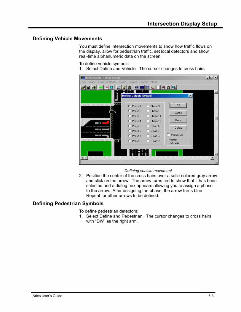
Intersection Display Setup
Aries User’s Guide 6-3
Defining Vehicle Movements You must define intersection movements to show how traffic flows on
the display, allow for pedestrian traffic, set local detectors and show real-time alphanumeric data on the screen. To define vehicle symbols: 1. Select Define and Vehicle. The cursor changes to cross hairs.
Defining vehicle movement
2. Position the center of the cross hairs over a solid-colored gray arrow and click on the arrow. The arrow turns red to show that it has been selected and a dialog box appears allowing you to assign a phase to the arrow. After assigning the phase, the arrow turns blue. Repeat for other arrows to be defined.
Defining Pedestrian Symbols To define pedestrian detectors:
1. Select Define and Pedestrian. The cursor changes to cross hairs with “DW” as the right arm.
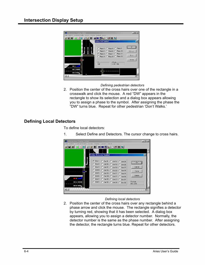
Intersection Display Setup
6-4 Aries User’s Guide
Defining pedestrian detectors
2. Position the center of the cross hairs over one of the rectangle in a crosswalk and click the mouse. A red “DW” appears in the rectangle to show its selection and a dialog box appears allowing you to assign a phase to the symbol. After assigning the phase the “DW” turns blue. Repeat for other pedestrian ‘Don’t Walks.’
Defining Local Detectors To define local detectors:
1. Select Define and Detectors. The cursor change to cross hairs.
Defining local detectors
2. Position the center of the cross hairs over any rectangle behind a phase arrow and click the mouse. The rectangle signifies a detector by turning red, showing that it has been selected. A dialog box appears, allowing you to assign a detector number. Normally, the detector number is the same as the phase number. After assigning the detector, the rectangle turns blue. Repeat for other detectors.

Intersection Display Setup
Aries User’s Guide 6-5
Add Text for Real-Time Alphanumeric Data Portions of the text you add are later displayed as dynamically-
changing, real-time alphanumeric data. This addition of text to Intersection Displays is optional, since the same information is also accessed through dialog boxes. To add text: 1. Select Define and Text. This brings up a Text menu. The Size menu
item allows the height of subsequent text entries to be changed, as measured in pixels per character.
Add text to the Intersection Zone display
2. Select Define, Text, Master and Number. The caption “Master No. 240” appears. This caption is placed anywhere in the display by clicking the left mouse button. Place it in a black area for best viewing. During later on-line operations, the “240” changes to the actual zone number.
3. To reposition the text entry, once more select Define, Text, Master and Number. This grabs the previous text entry and allows it to be moved.
4. Select Define, Text, Controller and Names. The resulting caption is replaced by the actual street names separated by an ampersand “&”, as shown in the Aries Zone Manager. The “ > ARTERIAL STREET NAME” is shown first as the right-left (or east-west) street in the Intersection Display. To have the north-south street shown first, put an asterisk (*) at the end of the second street in the Aries Zone Manager.
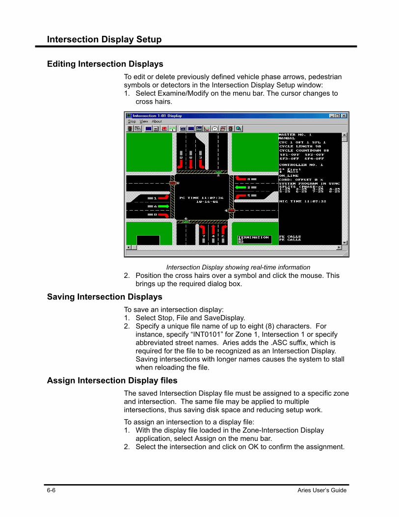
Intersection Display Setup
6-6 Aries User’s Guide
Editing Intersection Displays To edit or delete previously defined vehicle phase arrows, pedestrian
symbols or detectors in the Intersection Display Setup window: 1. Select Examine/Modify on the menu bar. The cursor changes to
cross hairs.
Intersection Display showing real-time information
2. Position the cross hairs over a symbol and click the mouse. This brings up the required dialog box.
Saving Intersection Displays To save an intersection display:
1. Select Stop, File and SaveDisplay. 2. Specify a unique file name of up to eight (8) characters. For
instance, specify “INT0101” for Zone 1, Intersection 1 or specify abbreviated street names. Aries adds the .ASC suffix, which is required for the file to be recognized as an Intersection Display. Saving intersections with longer names causes the system to stall when reloading the file.
Assign Intersection Display files The saved Intersection Display file must be assigned to a specific zone
and intersection. The same file may be applied to multiple intersections, thus saving disk space and reducing setup work. To assign an intersection to a display file: 1. With the display file loaded in the Zone-Intersection Display
application, select Assign on the menu bar. 2. Select the intersection and click on OK to confirm the assignment.
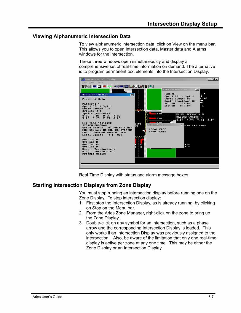
Intersection Display Setup
Aries User’s Guide 6-7
Viewing Alphanumeric Intersection Data To view alphanumeric intersection data, click on View on the menu bar.
This allows you to open Intersection data, Master data and Alarms windows for the intersection. These three windows open simultaneously and display a comprehensive set of real-time information on demand. The alternative is to program permanent text elements into the Intersection Display.
Real-Time Display with status and alarm message boxes
Starting Intersection Displays from Zone Display You must stop running an intersection display before running one on the
Zone Display. To stop intersection display: 1. First stop the Intersection Display, as is already running, by clicking
on Stop on the Menu bar. 2. From the Aries Zone Manager, right-click on the zone to bring up
the Zone Display. 3. Double-click on any symbol for an intersection, such as a phase
arrow and the corresponding Intersection Display is loaded. This only works if an Intersection Display was previously assigned to the intersection. Also, be aware of the limitation that only one real-time display is active per zone at any one time. This may be either the Zone Display or an Intersection Display.

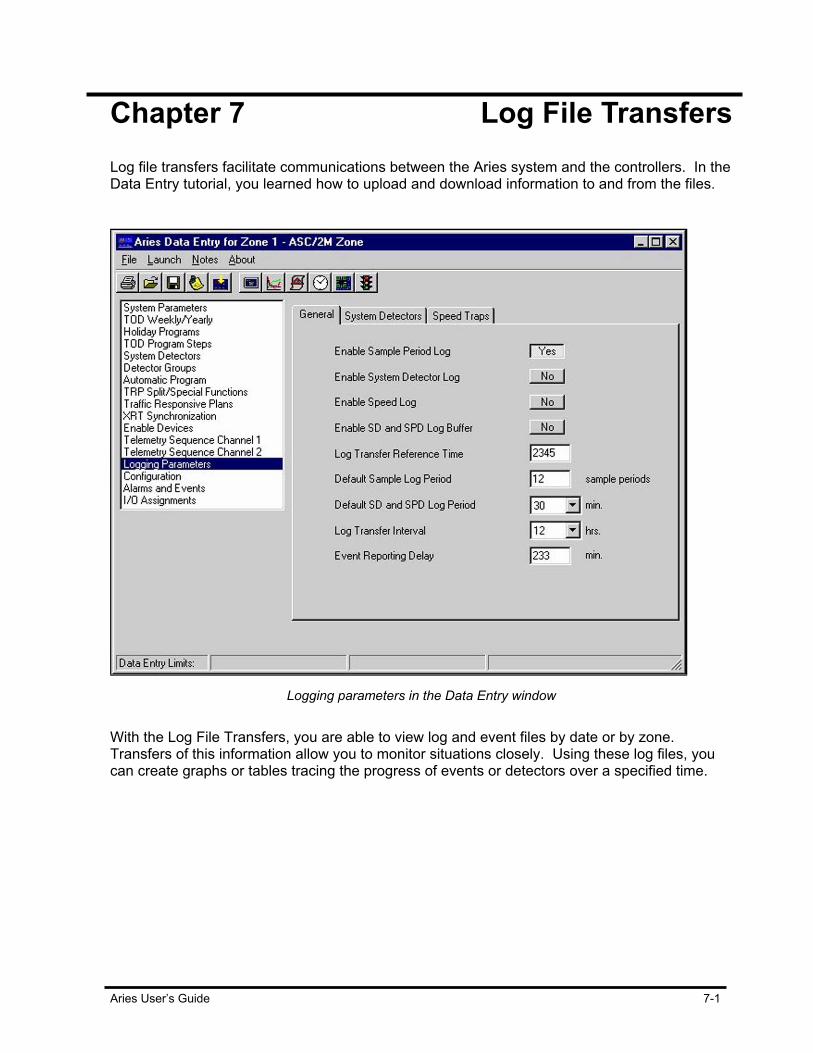
Aries User’s Guide 7-1
Chapter 7 Log File Transfers Log file transfers facilitate communications between the Aries system and the controllers. In the Data Entry tutorial, you learned how to upload and download information to and from the files.
Logging parameters in the Data Entry window
With the Log File Transfers, you are able to view log and event files by date or by zone. Transfers of this information allow you to monitor situations closely. Using these log files, you can create graphs or tables tracing the progress of events or detectors over a specified time.
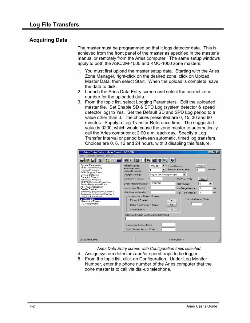
Log File Transfers
7-2 Aries User’s Guide
Acquiring Data The master must be programmed so that it logs detector data. This is
achieved from the front panel of the master as specified in the master’s manual or remotely from the Aries computer. The same setup windows apply to both the ASC/2M-1000 and KMC-1000 zone masters. 1. You must first upload the master setup data. Starting with the Aries
Zone Manager, right-click on the desired zone, click on Upload Master Data, then select Start. When the upload is complete, save the data to disk.
2. Launch the Aries Data Entry screen and select the correct zone number for the uploaded data.
3. From the topic list, select Logging Parameters. Edit the uploaded master file. Set Enable SD & SPD Log (system detector & speed detector log) to Yes. Set the Default SD and SPD Log period to a value other than 0. The choices presented are 0, 15, 30 and 60 minutes. Supply a Log Transfer Reference time. The suggested value is 0200, which would cause the zone master to automatically call the Aries computer at 2:00 a.m. each day. Specify a Log Transfer Interval or period between automatic, timed log transfers. Choices are 0, 6, 12 and 24 hours, with 0 disabling this feature.
Aries Data Entry screen with Configuration topic selected.
4. Assign system detectors and/or speed traps to be logged. 5. From the topic list, click on Configuration. Under Log Monitor
Number, enter the phone number of the Aries computer that the zone master is to call via dial-up telephone.
Log File Transfers
Aries User’s Guide 7-3
Downloading Setup Data to Master To download setup data to the master:
1. In the Aries Zone Manager window, right-click on the zone. 2. Select Download Master Data, then Start. This installs the detector
logging parameters in the zone master and initiates logging. Allow enough time for data to be collected before you attempt an upload, even the shortest logging period is 15 minutes.
Uploading Log Data from Master To upload log data from the master:
1. To upload logged data manually from the zone master to disk and select the Aries Zone Manager window.
2. Right-click on the zone, select Log Transfer and then Start. The resulting uploading of logged data may take several minutes, depending on the amount of data.
Select System Detectors for Viewing To select system detectors for viewing:
1. Select the Aries Zone Manager window. 2. From the menu bar, click on Launch and select Log File Manager.
This opens a window named Log File Tree. 3. Click on the icon for Detector Log Files, then click on the
appropriate “+” symbols to expand your selection to the desired year, month, day, zone and intersection. This lists the system detectors.
Viewing Detector Data as a Plot To view detector data as a plot:
1. Expand the detector tree until you reach the date and or/zone you want to view.
2. From the File menu and select New Window. Move the window to the right side of the screen.
3. Right-click on item you selected in step 1, drag the information over to the new window. As you drag the file, the item becomes an icon until you release it in the new window. Once released, a New Data Source dialog box appears.
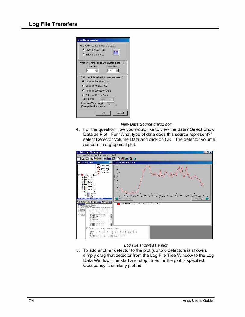
Log File Transfers
7-4 Aries User’s Guide
New Data Source dialog box
4. For the question How you would like to view the data? Select Show Data as Plot. For “What type of data does this source represent?” select Detector Volume Data and click on OK. The detector volume appears in a graphical plot.
Log File shown as a plot.
5. To add another detector to the plot (up to 8 detectors is shown), simply drag that detector from the Log File Tree Window to the Log Data Window. The start and stop times for the plot is specified. Occupancy is similarly plotted.

Log File Transfers
Aries User’s Guide 7-5
Viewing Detector Data as a Table To display the plotted data in tabular form:
1. Place the pointer anywhere on the plot and right-click the mouse. 2. Select Show Data as Text from the resulting dialog box. Detectors
are added to tables by dragging them from the left column to the plot. One column is shown per system detector. A table is converted back to a plot by right-clicking on it and selecting Show Data as Plot from the resulting dialog box.
Saving Detector Profiles To save a detector plot or table:
1. Place the pointer anywhere on the plot or table. 2. Right-click the mouse and select Save Detector Profile. The name
under which a Detector Profile is saved is a long alphanumeric descriptive title, which appears on the plot or table. This is not a file name.
Retrieve Detector Profile To retrieve a previously saved Detector Profile:
1. From the Aries Zone Manager, click Launch on the menu bar and select Log File Manager. This opens a window named Log File Tree.
2. Double-click on Detector Group Profiles. This displays a list of saved detector profiles, one of which should be the one that you saved in the previous step.
3. Right-click on it. The choices presented are Open Profile and Remove Profile.
4. Once the plot is opened, right-clicking on it presents the same dialog box that was used for the generation of the Detector Profile. One of the useful selections, at this stage is the Change Date feature, which allows the same plot to be displayed for historical data.
Export Detector Logs To export detector data to be used in an external program:
1. Export the detector data. 2. Select the Log File Tree and right-click on a detector. This time
select Export Detector Data. This allows volume or occupancy data for that detector to be saved under a user-specified path and file name.
Printing Plots & Tables To print a plot or table:
1. Right-click on the plot or table. In the dialog box, the print command appears as Print Table if the image is a table or Print Plot if the image is a graphic.
2. Select Print Plot or Print Table. Or, select File under the Aries File Manager and select Print Active
Data Window.

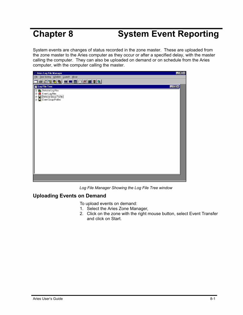
Aries User’s Guide 8-1
Chapter 8 System Event Reporting System events are changes of status recorded in the zone master. These are uploaded from the zone master to the Aries computer as they occur or after a specified delay, with the master calling the computer. They can also be uploaded on demand or on schedule from the Aries computer, with the computer calling the master.
Log File Manager Showing the Log File Tree window
Uploading Events on Demand To upload events on demand:
1. Select the Aries Zone Manager, 2. Click on the zone with the right mouse button, select Event Transfer
and click on Start.
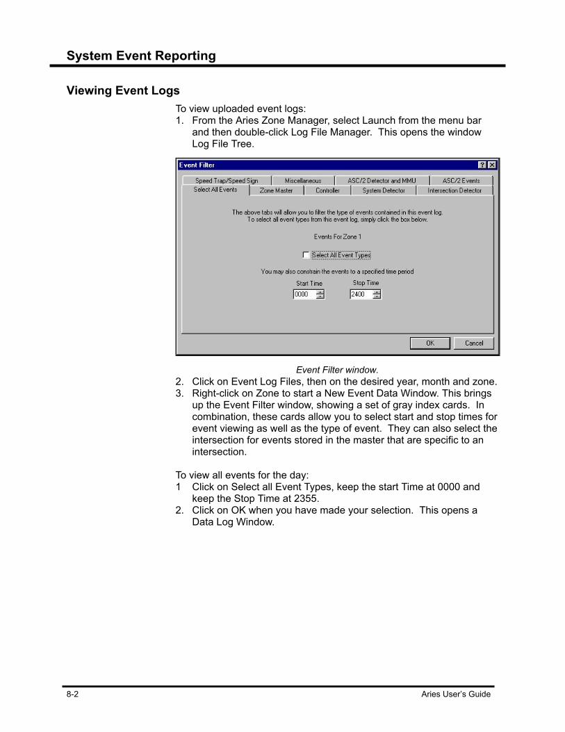
System Event Reporting
8-2 Aries User’s Guide
Viewing Event Logs
To view uploaded event logs: 1. From the Aries Zone Manager, select Launch from the menu bar
and then double-click Log File Manager. This opens the window Log File Tree.
Event Filter window.
2. Click on Event Log Files, then on the desired year, month and zone. 3. Right-click on Zone to start a New Event Data Window. This brings
up the Event Filter window, showing a set of gray index cards. In combination, these cards allow you to select start and stop times for event viewing as well as the type of event. They can also select the intersection for events stored in the master that are specific to an intersection.
To view all events for the day: 1 Click on Select all Event Types, keep the start Time at 0000 and
keep the Stop Time at 2355. 2. Click on OK when you have made your selection. This opens a
Data Log Window.
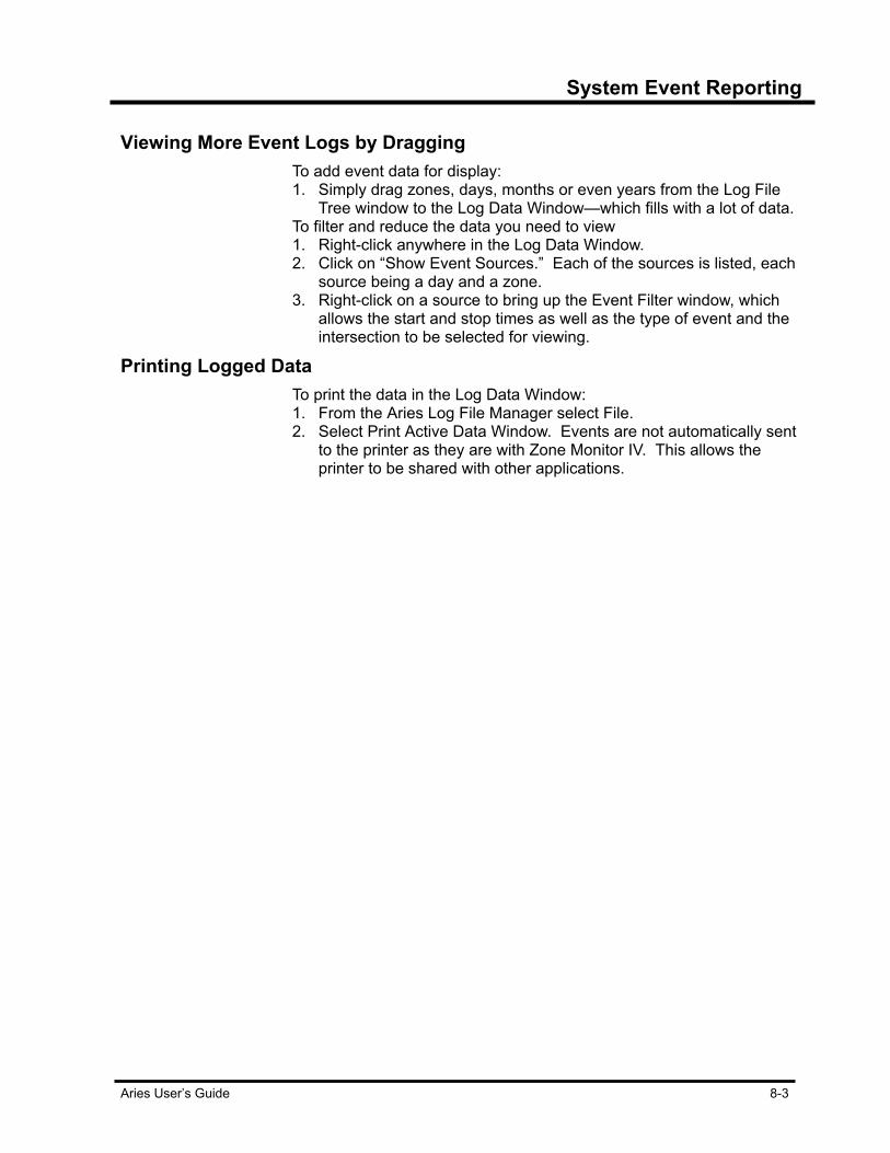
System Event Reporting
Aries User’s Guide 8-3
Viewing More Event Logs by Dragging To add event data for display:
1. Simply drag zones, days, months or even years from the Log File Tree window to the Log Data Window—which fills with a lot of data.
To filter and reduce the data you need to view 1. Right-click anywhere in the Log Data Window. 2. Click on “Show Event Sources.” Each of the sources is listed, each
source being a day and a zone. 3. Right-click on a source to bring up the Event Filter window, which
allows the start and stop times as well as the type of event and the intersection to be selected for viewing.
Printing Logged Data To print the data in the Log Data Window:
1. From the Aries Log File Manager select File. 2. Select Print Active Data Window. Events are not automatically sent
to the printer as they are with Zone Monitor IV. This allows the printer to be shared with other applications.


Aries User’s Guide 9-1
Chapter 9 Operations Scheduling Aries Operations Scheduler operations are initiated either manually or scheduled for automatic, unattended operation. Set operations to function immediately for manual or set them to run in the future singularly or in a repeatable pattern. Use the pull-down menus to create scheduled operations, suspend scanning or set values for various options. The word “scanning” refers to the process of continually looking for operations that need to be executed.
Operations Scheduler window
When active, Scheduler looks through the list of operations. Operations that have the status of Active are checked. Operations that were not completed for any reason, such as a power outage, are changed to Enabled status and are performed again. Scheduler attempts to perform any operations having a start date and time older than the current date and time. Operations with past start times are then activated with operations having the same dates and times run in order of the priority level assigned them. When one or more operations are active, you are not allowed to create, edit or delete operations.

Operations Scheduling
9-2 Aries User’s Guide
Creating Scheduled Operations To create a new operation:
1. To suspend operations; select Schedule Operations from the pull down menus and click on Suspend Scanning for Operations. Creating, editing or viewing other operations is not possible when an operation is running.
2. In the Operations Scheduler window, select Schedule Operation. This brings up the Operation Definition dialog box.
Operation Definition dialog box
3. Select the operation you want to define and click on OK. This action brings up the Schedule Operation dialog box.
4. The Scheduled Operation dialog box contains two tabs. The Intersection Definition allows one or multiple intersections to be selected for the operation. The Time/Date tab allows you to set the time and date for the operation, as well as setting the operation’s priority.

Operations Scheduling
Aries User’s Guide 9-3
Scheduler Operation dialog box
There are also two repeat functions. “Repeat every…” allows you to set a number of minutes, hours, days, weeks, months or years for the action to repeat itself. “Repeat through’ allows you to set a definite time period of repeat operations. “Repeat forever” allows you to set an infinite time period of repeat operations.
Setting Global Parameters To set global operating parameters:
1. From the Operations Scheduler window, select the File selection on the menu bar.
2. Select Set Time-Out Value. This allows a time to be set in minutes (from 1 to 60) for how long the Aries computer tries to connect with a remote device that is not responding before it declares a failure. Other global parameters are:
• Print Progress List provides a printed log of operations events as they occur.
• Clear Progress List clears the contents of the lower window. • Log Messages logs operations as they occur as a text file
called SCHEDULE.LOG in the \ECONLITE\ZMLOGS directory.
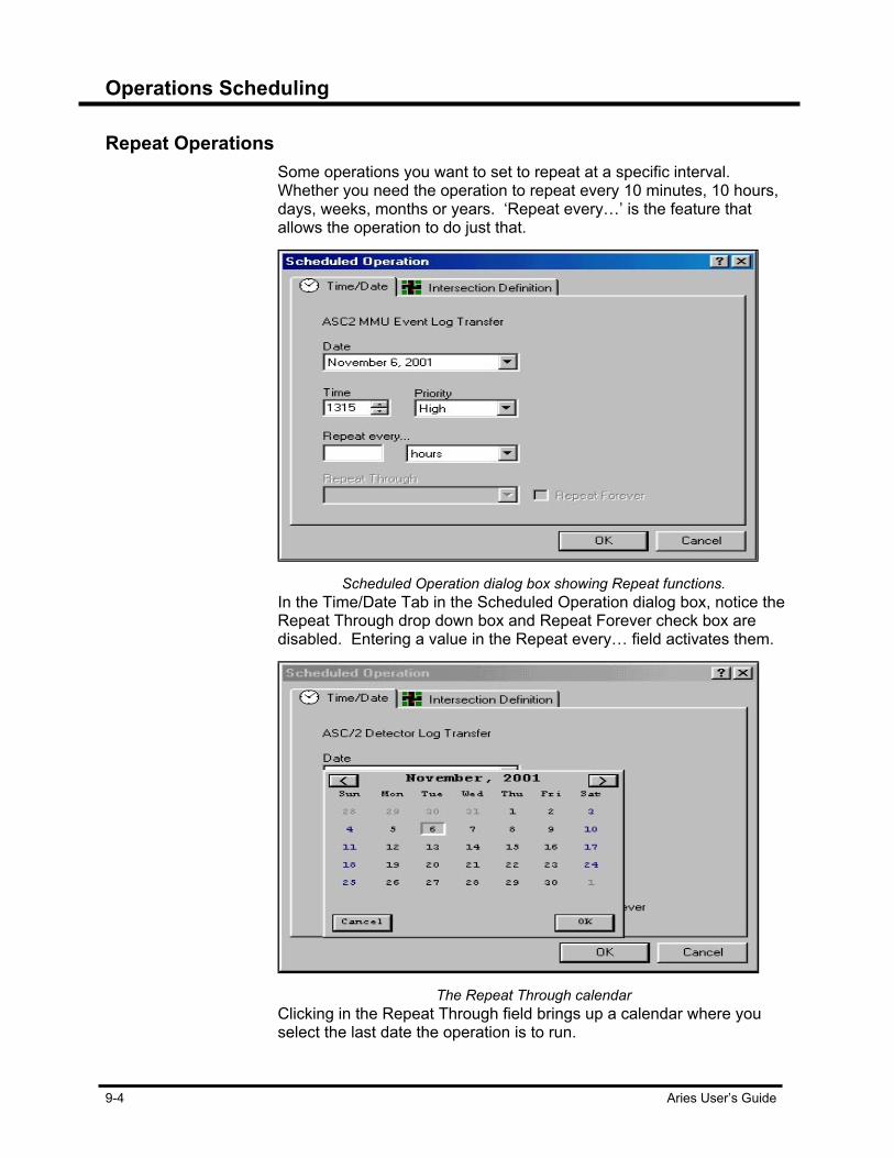
Operations Scheduling
9-4 Aries User’s Guide
Repeat Operations Some operations you want to set to repeat at a specific interval.
Whether you need the operation to repeat every 10 minutes, 10 hours, days, weeks, months or years. ‘Repeat every…’ is the feature that allows the operation to do just that.
Scheduled Operation dialog box showing Repeat functions.
In the Time/Date Tab in the Scheduled Operation dialog box, notice the Repeat Through drop down box and Repeat Forever check box are disabled. Entering a value in the Repeat every… field activates them.
The Repeat Through calendar
Clicking in the Repeat Through field brings up a calendar where you select the last date the operation is to run.
Operations Scheduling
Aries User’s Guide 9-5
Repeat Forever Option Clicking on the Repeat Forever check box disables the Repeat Through
function. The Repeat Forever option allows the operation to do just that, repeat an operation forever, so there is no need for a stop date/time. To remove the repeat forever selection: 1. From the Aries Operations Scheduler window, right-click on the
scheduled event and select Edit Operation. 2. Select the Time/Date tab from the Scheduled Operation dialog box
and click in the Repeat forever check box. This disables the Repeat Forever option and allows you to select a time when the operation will stop running.
Viewing Scheduled Operations From the Aries Zone Manager, select Launch and Operations
Scheduler. Aries Operations Scheduler window appears. Scheduler is divided into two sections. The top section shows scheduled operations, the bottom section provides progress messages. Operations can have the status enabled, disabled, active (operation in progress), completed or failed, as indicated in the Status column. The column widths are changed by dragging. Clicking on any column heading sorts all row entries below to facilitate review. The splitter bar between the top and bottom sections can also be moved by dragging.
Editing Scheduled Operations To change a previously entered operation:
1. Select the Aries Operations Scheduler window. 2. Select Schedule Operation and click on Suspend Scanning for
Operations. When scheduler is running, you are unable to access any of the scheduled operations to create, edit or view them. If the event is currently active (i.e., in progress), it is canceled, thereby producing a failed status.

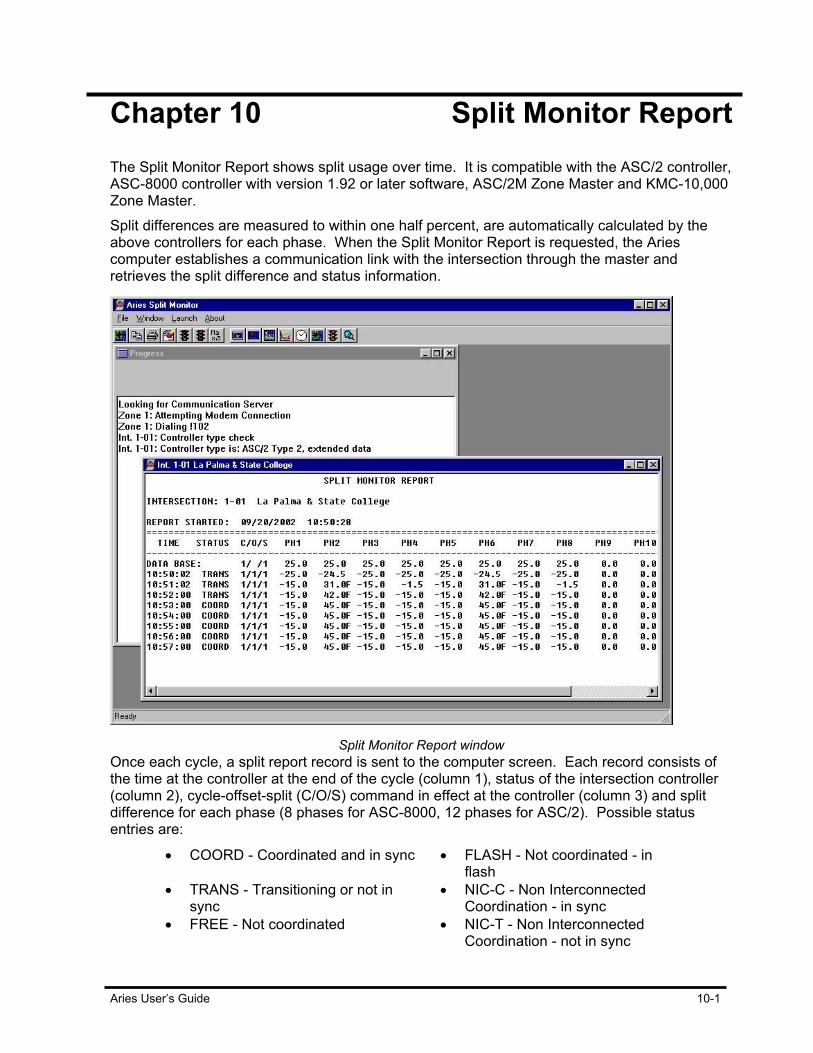
Aries User’s Guide 10-1
Chapter 10 Split Monitor Report The Split Monitor Report shows split usage over time. It is compatible with the ASC/2 controller, ASC-8000 controller with version 1.92 or later software, ASC/2M Zone Master and KMC-10,000 Zone Master. Split differences are measured to within one half percent, are automatically calculated by the above controllers for each phase. When the Split Monitor Report is requested, the Aries computer establishes a communication link with the intersection through the master and retrieves the split difference and status information.
Split Monitor Report window
Once each cycle, a split report record is sent to the computer screen. Each record consists of the time at the controller at the end of the cycle (column 1), status of the intersection controller (column 2), cycle-offset-split (C/O/S) command in effect at the controller (column 3) and split difference for each phase (8 phases for ASC-8000, 12 phases for ASC/2). Possible status entries are:
• COORD - Coordinated and in sync • FLASH - Not coordinated - in flash
• TRANS - Transitioning or not in sync
• NIC-C - Non Interconnected Coordination - in sync
• FREE - Not coordinated • NIC-T - Non Interconnected Coordination - not in sync

Split Monitor Reporting
10-2 Aries User’s Guide
Split differences are actual splits minus programmed splits at the controller in percent. If the split difference is positive, the phase has timed longer than the programmed split. If it is negative, the phase has not timed its allocated split. If the phase is forced off, an F is appended to the end of the number.
Manual or Scheduled Operations Split monitor reports are initiated manually from the Aries computer or
can be scheduled for automatic operation. This User’s Guide section limits itself to manual operation.
Open a Split Monitor Report window 1. Select the Aries Zone Manager and click on Split Monitor Report on
the Launch pull-down menu. Or, Click on the Split Monitor icon in the Aries group window. The Aries Split Monitor window appears with a superimposed window entitled Progress.
Split Monitor Report window with Progress Window active.
2. Open the File pull-down menu and click on Load Intersection. A Zone, Intersection tree appears.
3. Double-click on the desired zone, select the intersection and click on OK. This opens the Intersection Status Report window with the name of the intersection on top.
Multiple Split Monitor Report Windows The Aries Split Monitor application provides a multiple document
interface, allowing multiple intersections within the same zone to open at the same time.
1. Select multiple Split Monitor Report windows.
Note: all open Split Monitor windows are listed at bottom of the pull-down window.

Split Monitor Reporting
Aries User’s Guide 10-3
2. Open the Window pull-down menu from the Aries Split Monitor window and rearrange the window layout by selecting Cascade and Tile.
Uploading Database for Split Monitor Report Before you activate (or run) a Split Monitor Report, upload the current
controller database.
Activate Split Monitor Report 1. Open the File pull-down menu.
2. Select Begin Data Acquisition. A record is added as a new line at the end of each cycle.
Ending, Saving and Appending to Split Monitor Report To end Split Monitor data acquisition:
1. Open the File pull-down menu and click on End Data Acquisition or Close.
2. Close the report with a time and date stamped entry with paper tear marks. This also automatically saves the data on disk.
3. Restarting data acquisition for the intersection by selecting Begin Data Acquisition from the File pull-down menu. Begin Data Acquisition recalls the saved data and appends new data.
To erase the Split Monitor file for an intersection: 1. Open the File pull-down menu. 2. Click on Clear.
Printing All or Selection of Split Monitor Report To print all of a Split Monitor Report:
1. Open the File pull-down menu and click on Print. A Windows dialog box appears giving you the option to print All or selected Pages.
2. To print a selection of the report, drag the mouse over the selected lines, they appear highlighted.
3. Again open the File pull-down menu and click on Print. This time, the Windows dialog box also shows Selection, which is what you choose.
Note: all open Split Monitor windows are listed at bottom of the pull-down window.

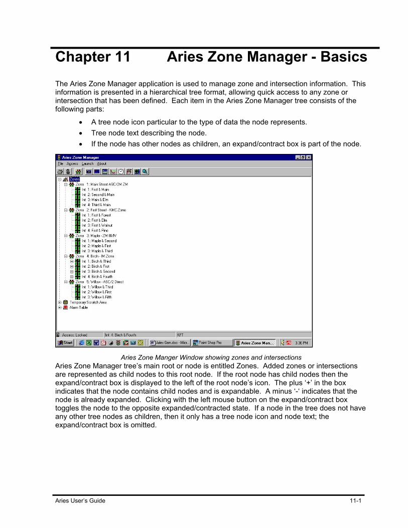
Aries User’s Guide 11-1
Chapter 11 Aries Zone Manager - Basics The Aries Zone Manager application is used to manage zone and intersection information. This information is presented in a hierarchical tree format, allowing quick access to any zone or intersection that has been defined. Each item in the Aries Zone Manager tree consists of the following parts:
• A tree node icon particular to the type of data the node represents. • Tree node text describing the node. • If the node has other nodes as children, an expand/contract box is part of the node.
Aries Zone Manger Window showing zones and intersections
Aries Zone Manager tree’s main root or node is entitled Zones. Added zones or intersections are represented as child nodes to this root node. If the root node has child nodes then the expand/contract box is displayed to the left of the root node’s icon. The plus ‘+’ in the box indicates that the node contains child nodes and is expandable. A minus ‘-‘ indicates that the node is already expanded. Clicking with the left mouse button on the expand/contract box toggles the node to the opposite expanded/contracted state. If a node in the tree does not have any other tree nodes as children, then it only has a tree node icon and node text; the expand/contract box is omitted.
Aries Zone Manager – Basics
11-2 Aries User’s Guide
The children of the root node are the zone nodes. There is one node for each zone defined in the system. Any of these zone nodes which have intersections defined for them have an expand/contract box displayed next to them. Expanding a zone node causes the child intersection nodes to be displayed. Expanding and contracting a node with children is performed by double-clicking with the left mouse button anywhere on the node icon or the node text. Double-clicking on a node item which does not have any child nodes has no effect. The tree node which is highlighted is considered the selected node. There is only one selected node at a time. A node becomes selected when you click anywhere on it with the left or right mouse buttons. In addition to the Zones root node, there are two additional main nodes: the Alarm Table and Temporary Scratch Area nodes. The Alarm Table node is the main node for the alarm table entries. The children of this node are the separate alarm table entries. There is one child node for each of the 20 alarm table entries. The Temporary Scratch Area serves as the main node for the Temporary Scratch Node. Refer to the section Temporary Scratch Node for instructions on accessing this functionality.
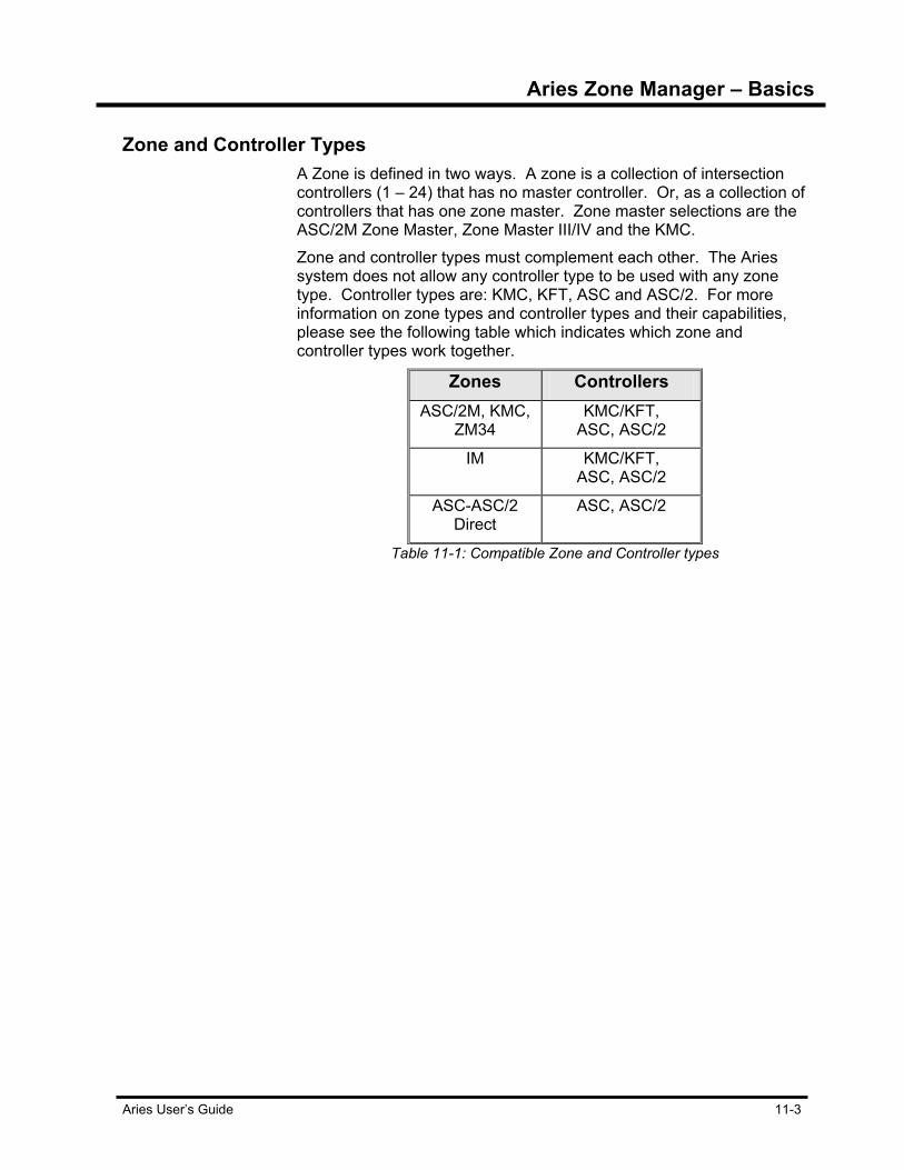
Aries Zone Manager – Basics
Aries User’s Guide 11-3
Zone and Controller Types
A Zone is defined in two ways. A zone is a collection of intersection controllers (1 – 24) that has no master controller. Or, as a collection of controllers that has one zone master. Zone master selections are the ASC/2M Zone Master, Zone Master III/IV and the KMC. Zone and controller types must complement each other. The Aries system does not allow any controller type to be used with any zone type. Controller types are: KMC, KFT, ASC and ASC/2. For more information on zone types and controller types and their capabilities, please see the following table which indicates which zone and controller types work together.
Zones Controllers ASC/2M, KMC,
ZM34 KMC/KFT,
ASC, ASC/2
IM KMC/KFT, ASC, ASC/2
ASC-ASC/2 Direct
ASC, ASC/2
Table 11-1: Compatible Zone and Controller types

Aries Zone Manager – Basics
11-4 Aries User’s Guide
File Menu Options File menu options are accessible by clicking on the File selection in the
Menu bar, across the top of the Aries Zone Manager window.
Print Tree Use the Print Tree command to print a copy of the Aries Zone Manager
window.
Print options dialog box.
To use the print tree command: 1. From the Menu bar, select File. 2. Select the Print Tree command and the print options dialog box
appears. This dialog box allows you the options of printing all nodes, only visible nodes and, in certain circumstances, to print the Controller and/or Master database.
Find Text The Find Text option allows you to find the data you need.
Find Text dialog box
To begin a search: 1. Enter any alphanumeric text string in the search field. 2. Click on Find Next and the system locates the text matching that
entered in the dialog box.

Aries Zone Manager – Basics
Aries User’s Guide 11-5
Backup Aries System Aries provides the ability to backup and archive important application
data as well as restore this data from the backup file. The backup process compresses the Aries data and creates a user named backup file which is compatible with the PKWare archive format. To initiate a backup of the Aries system data: 1. Select the Backup Aries System command from the Aries Zone
Manager File menu item. The Backup dialog appears.
Backup and Restore window
2. In the Backup dialog, select which portions of the system you wish to backup. The data available for inclusion in the backup include: Aries Configuration File Master and Local Controller Databases Log and Event Files Graphics Files
Aries applications are not a selection for backup since these are restored by re-installing from the Aries installation disks.

Aries Zone Manager – Basics
11-6 Aries User’s Guide
3. Select any combination of these data items by checking the box next to their names. After this selection, you must select a location to place the backup file and a name for the backup file. “Ariesbkp.zip” appears as a default name. If desired, use the directory and drive controls to choose a new location for the backup file. Change the name of the file and delete the current name if desired. It is recommended that you use a “zip” extension, since the backup file is compatible with the PKWare archive format.
4. After the data items are chosen and specified its location and name, press the Backup button. This begins the backup process.
Backing up Aries
While the backup is being performed, the progress is shown in the lower left side of the Backup dialog. The name of the current data file being archived is displayed above the progress bar, which indicates the relative completion of the backup process. Currently the Aries backup process does not place the backup file on multiple disks. Therefore, if the backup destination is a floppy disk and the backup file exceeds the storage space available on the disk, the backup process fails. Some suggested solutions would be to create partial backups that would fit on a floppy disk or to change the destination of the backup file to be on the hard disk. The Log and Event Files and Graphic Files data have the possibility of being quite large, so prudent backup of this data may be required.
Restore Aries System Previously archived Aries application data (done using the Aries
Backup process) is restored using the Aries Restore process. To restore the Aries system: 1. Select the Restore Aries System command from the Aries Zone
Manager File menu item. Aries checks to see if any other Aries applications are currently running.
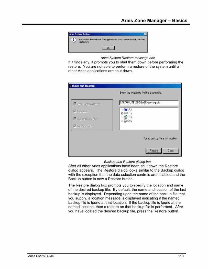
Aries Zone Manager – Basics
Aries User’s Guide 11-7
Aries System Restore message box
If it finds any, it prompts you to shut them down before performing the restore. You are not able to perform a restore of the system until all other Aries applications are shut down.
Backup and Restore dialog box
After all other Aries applications have been shut down the Restore dialog appears. The Restore dialog looks similar to the Backup dialog with the exception that the data selection controls are disabled and the Backup button is now a Restore button. The Restore dialog box prompts you to specify the location and name of the desired backup file. By default, the name and location of the last backup is displayed. Depending upon the name of the backup file that you supply, a location message is displayed indicating if the named backup file is found at that location. If the backup file is found at the named location, then a restore on that backup file is performed. After you have located the desired backup file, press the Restore button.
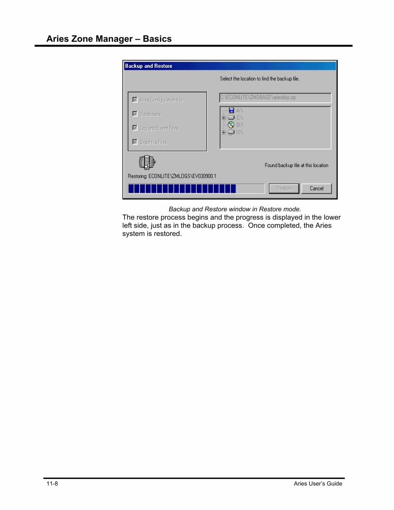
Aries Zone Manager – Basics
11-8 Aries User’s Guide
Backup and Restore window in Restore mode.
The restore process begins and the progress is displayed in the lower left side, just as in the backup process. Once completed, the Aries system is restored.
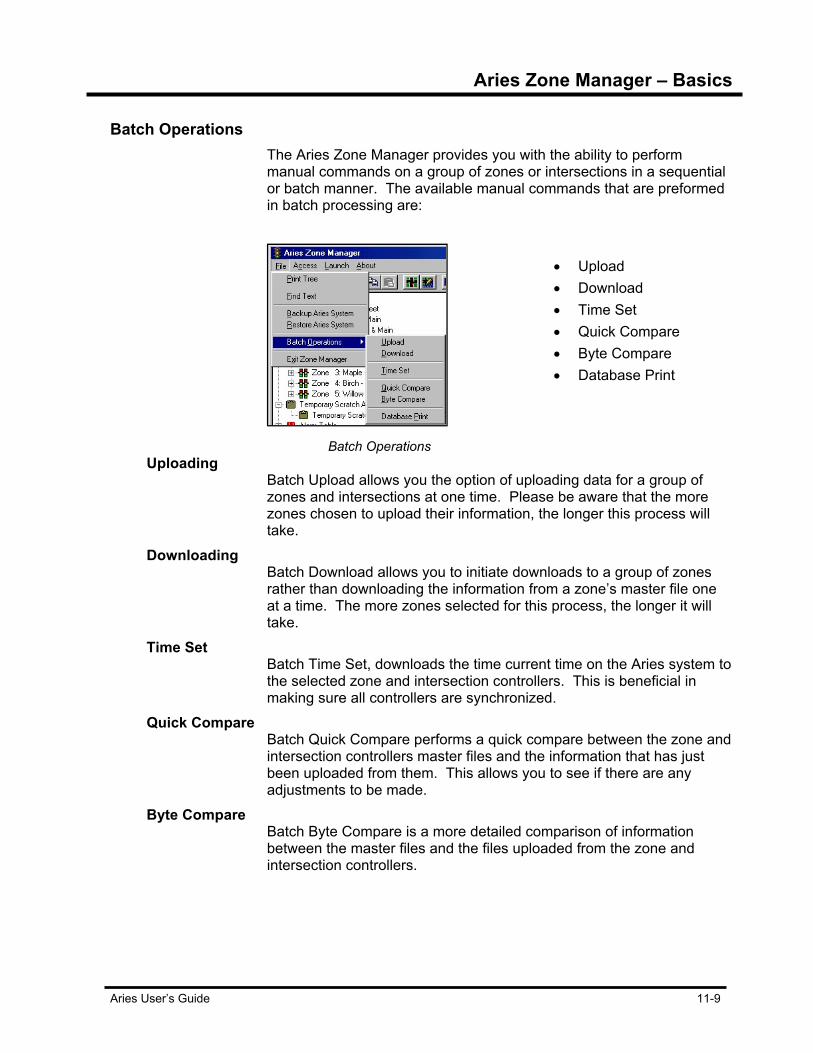
Aries Zone Manager – Basics
Aries User’s Guide 11-9
Batch Operations The Aries Zone Manager provides you with the ability to perform manual commands on a group of zones or intersections in a sequential or batch manner. The available manual commands that are preformed in batch processing are:
Batch Operations
• Upload • Download • Time Set • Quick Compare • Byte Compare • Database Print
Uploading Batch Upload allows you the option of uploading data for a group of
zones and intersections at one time. Please be aware that the more zones chosen to upload their information, the longer this process will take.
Downloading Batch Download allows you to initiate downloads to a group of zones
rather than downloading the information from a zone’s master file one at a time. The more zones selected for this process, the longer it will take.
Time Set Batch Time Set, downloads the time current time on the Aries system to
the selected zone and intersection controllers. This is beneficial in making sure all controllers are synchronized.
Quick Compare Batch Quick Compare performs a quick compare between the zone and
intersection controllers master files and the information that has just been uploaded from them. This allows you to see if there are any adjustments to be made.
Byte Compare Batch Byte Compare is a more detailed comparison of information
between the master files and the files uploaded from the zone and intersection controllers.
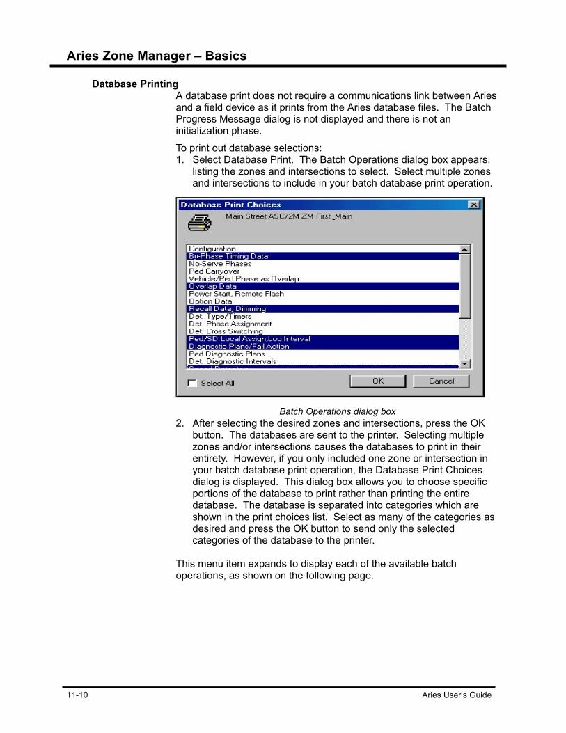
Aries Zone Manager – Basics
11-10 Aries User’s Guide
Database Printing
A database print does not require a communications link between Aries and a field device as it prints from the Aries database files. The Batch Progress Message dialog is not displayed and there is not an initialization phase. To print out database selections: 1. Select Database Print. The Batch Operations dialog box appears,
listing the zones and intersections to select. Select multiple zones and intersections to include in your batch database print operation.
Batch Operations dialog box
2. After selecting the desired zones and intersections, press the OK button. The databases are sent to the printer. Selecting multiple zones and/or intersections causes the databases to print in their entirety. However, if you only included one zone or intersection in your batch database print operation, the Database Print Choices dialog is displayed. This dialog box allows you to choose specific portions of the database to print rather than printing the entire database. The database is separated into categories which are shown in the print choices list. Select as many of the categories as desired and press the OK button to send only the selected categories of the database to the printer.
This menu item expands to display each of the available batch operations, as shown on the following page.

Aries Zone Manager – Basics
Aries User’s Guide 11-11
Batch Operations dialog box
1. Select the desired operation. A list of available zones and intersections appears.
2. Select as many zones and intersections as needed. To select multiple items from the list, click on the desired item and hold down the “Ctrl” key. When you have selected all of the zones and intersections necessary, press the OK button.
3. The Batch Progress Messages dialog is displayed. This dialog box shows messages concerning the progress of the batch operations on each zone and intersection, as well as a list of pending and completed portions of the batch operation.
Batch Operation Progress Message window.
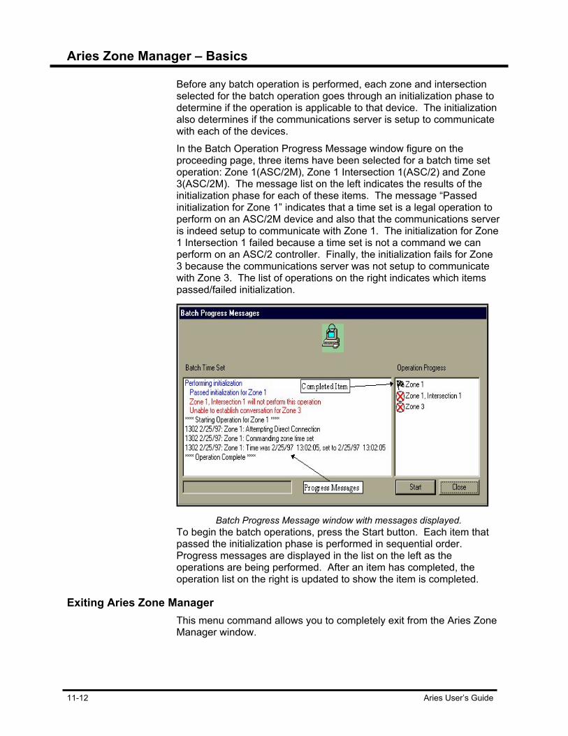
Aries Zone Manager – Basics
11-12 Aries User’s Guide
Before any batch operation is performed, each zone and intersection selected for the batch operation goes through an initialization phase to determine if the operation is applicable to that device. The initialization also determines if the communications server is setup to communicate with each of the devices. In the Batch Operation Progress Message window figure on the proceeding page, three items have been selected for a batch time set operation: Zone 1(ASC/2M), Zone 1 Intersection 1(ASC/2) and Zone 3(ASC/2M). The message list on the left indicates the results of the initialization phase for each of these items. The message “Passed initialization for Zone 1” indicates that a time set is a legal operation to perform on an ASC/2M device and also that the communications server is indeed setup to communicate with Zone 1. The initialization for Zone 1 Intersection 1 failed because a time set is not a command we can perform on an ASC/2 controller. Finally, the initialization fails for Zone 3 because the communications server was not setup to communicate with Zone 3. The list of operations on the right indicates which items passed/failed initialization.
Batch Progress Message window with messages displayed.
To begin the batch operations, press the Start button. Each item that passed the initialization phase is performed in sequential order. Progress messages are displayed in the list on the left as the operations are being performed. After an item has completed, the operation list on the right is updated to show the item is completed.
Exiting Aries Zone Manager This menu command allows you to completely exit from the Aries Zone
Manager window.

Aries Zone Manager – Basics
Aries User’s Guide 11-13
Access Menu The application menu at the top of the Aries Zone Manager window
contains a section labeled Access. Explicitly lock or unlock the data access state by using the pull-down menu commands. The available choices under this item are Lock, Unlock, Data Change and Supervisor.
Lock/Unlock The Lock/Unlocked status of the Aries system is indicated in the lower
left hand corner of the system’s window. A lock icon is followed by the phrase ‘Access: Locked’ or ‘Access: Unlocked.’ In several of the applications, you need to unlock the system before you can perform the specific task. In the Access Menu, when the Lock menu item is disabled and the Unlock menu item is enabled. Likewise, if the system is unlocked when the menu is displayed, the Unlock menu item is disabled and the Lock item is enabled.
Lock/Unlock dialog box
When the data state is locked, attempting to unlock it requires the Supervisor Access Code. Upon successful entry of the Supervisor Access Code, the data access state is unlocked.
Data Change and Supervisor These commands allow you to change the Supervisor and Data
Change Access. In both cases, the current Supervisor Access Code must be entered in the Change Access Code dialog box before you are allowed to enter a new Supervisor or Data Change Access Code.
Deleting Data Change and Supervisor Access Codes These commands allow you to delete the Supervisor and Data Change
Access. In both cases, the current Supervisor Access Code must be entered in the Change Access Code dialog box before you are allowed to enter a new Supervisor or Data Change Access Code. Be aware that the changed codes are permanent.


Aries User’s Guide 12-1
Chapter 12 Aries Zone Manager Zone Controllers To perform many of the operations on zones and intersections, the Aries Zone Manager relies on pop-up menus invoked via the right-mouse button. When the cursor is over a tree node and the right-mouse button is clicked, a pop-up menu appears. The items in the pop-up menu are determined by the type of zone node and intersection node selected. The root node, zone nodes and intersection nodes all have distinctly different pop-up menus.
Zone selected with command pop-up menu shown.
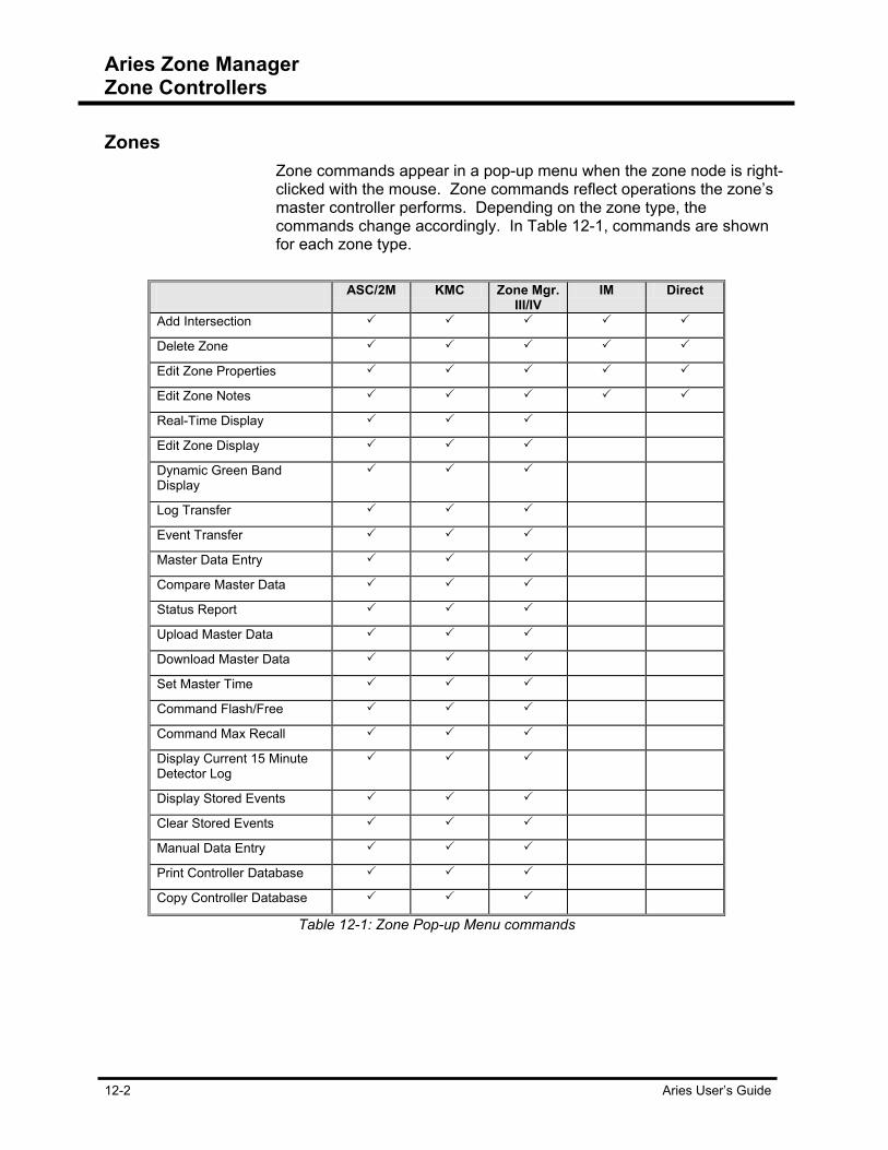
Aries Zone Manager Zone Controllers
12-2 Aries User’s Guide
Zones Zone commands appear in a pop-up menu when the zone node is right-
clicked with the mouse. Zone commands reflect operations the zone’s master controller performs. Depending on the zone type, the commands change accordingly. In Table 12-1, commands are shown for each zone type.
ASC/2M KMC Zone Mgr.
III/IV IM Direct
Add Intersection
Delete Zone
Edit Zone Properties
Edit Zone Notes
Real-Time Display
Edit Zone Display
Dynamic Green Band Display
Log Transfer
Event Transfer
Master Data Entry
Compare Master Data
Status Report
Upload Master Data
Download Master Data
Set Master Time
Command Flash/Free
Command Max Recall
Display Current 15 Minute Detector Log
Display Stored Events
Clear Stored Events
Manual Data Entry
Print Controller Database
Copy Controller Database
Table 12-1: Zone Pop-up Menu commands

Aries Zone Manager Zone Controllers
Aries User’s Guide 12-3
Root Node Menu Access the Root Node Menu by right-clicking-mouse button when the
cursor is over the Zone Manager root node which has the name Zones.
Root Node Menu
This menu provides only two functions. The Add Zone menu command is used to add new zones to your system. The Refresh command refreshes the Zone Manager display with the most current zone and intersection data. The Refresh command is also initiated by pressing the F5 key on the keyboard.
Add Zone Node Dialog Box When you have chosen Add Zone from the Root Node Menu, the Add
Zone Node dialog box is displayed. This dialog provides boxes for you to enter all the information about the zone to be added. The zone number automatically defaults to the next available zone number in the system. Change the number to any zone number you wish, provided that the zone number is not already being used. The Telephone number field box is where you enter the modem number that allows you to upload and download information from that zone. Enter the Zone name. When naming a zone, keep the naming conventions simple.

Aries Zone Manager Zone Controllers
12-4 Aries User’s Guide
Add Zone Node dialog box
The Zone Type box contains five choices for the type of zone; the KMC Zone, the IM Zone, the Zone Master III/IV, the ASC-ASC/2 Direct Zone and the ASC/2M Zone Master. Depending on the zone type selected, the Telephone Number and Bit Rate boxes may be disabled, as a phone number is not necessary for some zone types. Choosing a bit rate from the Bit Rate box allows you to choose the data transfer speed rate from either 300 bps, 1200 bps or 2400 bps. The default is 300 bps. The Access Code box allows you to enter in a four-digit access code for this zone. When you have finished entering in the information for the zone, clicking on the OK button causes this zone to be added to the system and the Aries Zone Manager display is updated to reflect the new zone. If you decide that you do not wish to add this zone after all, clicking on the Cancel button causes the dialog to disappear and the zone information is ignored.
Zone Node Menus Access the Zone Node Menu by right-clicking mouse button when the
cursor is anywhere over a zone node. The pop-up menu contains functions which operate directly on a zone or are related to a zone. Each of the commands in the Zone Node Menu is described in the following paragraphs.

Aries Zone Manager Zone Controllers
Aries User’s Guide 12-5
Adding an Intersection Node Add Intersection menu item allows you to add intersection nodes to a
selected zone node. Select a zone node where an intersection is to be added. Right-click the mouse button to bring up the Zone Node Menu and it is highlighted.
Add intersection dialog box
Similar to the Add Zone Node dialog box, the Add Intersection dialog box provides fields for you to enter all the information about the intersection. The intersection number automatically defaults to the next available intersection number within the selected zone. Any intersection number may be used as long as that number is not already being used within the selected zone. The Controller Type box allows you to change the specified controller type for this intersection. If a controller type for this intersection already exists, its type is displayed in this box. ‘Undefined,’ appears to indicate a controller type needs to be chosen. The intersection name is a required entry. Enter a descriptive name in the intersection name field The Telephone Number and Bit Rate fields may or may not be disabled, depending on the zone type selected. If the zone type activates an intersection node requiring the telephone numbers, these fields are enabled and you are able to enter values for them. However, if the zone type contains the telephone number, then these fields are disabled in the Add Intersection Node dialog box.

Aries Zone Manager Zone Controllers
12-6 Aries User’s Guide
Based on the type of controller selected, you are presented with a controller sub-type dialog when OK is pressed. If you decide that you do not wish to add this intersection after all, clicking on the Cancel button causes the Add Intersection Node dialog to disappear and the intersection information is ignored. After selecting the desired controller sub-type, the intersection is added to the selected zone and a controller file of the appropriate type is created. The Zone Manager Display is updated to reflect the new intersection.
Deleting Zone Node This command allows you to remove zone nodes from the system.
Selection of this command brings up a message box asking: “Do you want to remove this zone and all of its intersections?” Your choices are YES and NO. Selecting YES causes the selected zone node and any underlying intersection nodes are removed. The Zone Manager display is updated to reflect these changes. Selecting NO aborts the deletion process, so the zone and its intersections remain intact.
Editing Zone Properties Previously entered zone information may be edited by bringing up the
Edit Zone dialog box. Similar to the Add Zone dialog box, this dialog box has the zone number field disabled as zone numbers are permanent once they are defined for a zone. Change the telephone number, bit rate, zone name, zone type or access codes as necessary. The telephone number and bit rate boxes are displayed if the zone type is such that they are required. If a mistake in zone number was made, delete that zone node using the procedure described previously. Then add a zone node with the correct zone number information. Clicking on the OK button causes any changes to be incorporated and the Aries Zone Manager display to be updated to reflect any changes. Clicking on Cancel causes the Edit Zone Node dialog to disappear and all changes are ignored.
Editing Zone Notes This menu item allows you to edit and print the user notes stored for
this zone. Selecting this menu item creates a Notes dialog box. The toolbar at the top of the dialog provides you with the capability to save any changes you make to the notes, to print the notes and the functions of text cut, copy and paste. When you have finished editing the notes, press the Close button.

Aries Zone Manager Zone Controllers
Aries User’s Guide 12-7
Display Commands Display commands allows you to execute several functions such as,
editing the zone display, or by connecting to the zone’s controller, to perform real-time displays or view a Dynamic Green Band Display
Perform Real-Time Displays This menu item starts a Zone Display for the selected zone node by
bringing up the Zone-Intersection Display application. The Zone-Intersection Display application runs independently of the Aries Zone Manager application.
Editing Zone Displays This menu item allows you to edit a zone display for the selected zone
node by invoking the Zone-Intersection Display application. The Zone-Intersection Display application runs independently of the Aries Zone Manager application.
Dynamic Green Band Display This menu item starts a Dynamic Green Band Display for the selected
zone node by bringing up the Dynamic Green Band Display application. The Dynamic Green Band Display presents a real-time graphics display of arterial or a cross street. Signals and detectors are depicted in true scale along. What is created is a continuously updated green band display of the intersections. If you are familiar with a time/space diagram, the green band display is what would be shown by a 1-second window moving in the time direction on a time/space diagram.
Aries Zone Manager Zone Controllers
12-8 Aries User’s Guide
Transfer Commands Selecting the transfer command for log or event, connects you to the
controller and uploads log and event records.
Log Transfer The Log Transfer uploads log information from a zone controller.
These logs contain detector records pertaining to volume counts, occupancy logs and speed trap occurrences. During the upload process this information appears in the Operation Progress window and are saved to the hard drive.
Event Transfer Event logs are reports pertaining to any occurrence recorded by the
event detectors. These occurrences are recorded in 15-minute increments and listed in that manner in the log. During the upload process this information appears in the Operation Progress window and is saved to the hard drive.

Aries Zone Manager Zone Controllers
Aries User’s Guide 12-9
Master Data Management Commands Master Data Management command allows you to easily access the
Data Entry application. Selecting any of the following commands immediately establishes a dial-up connection to the system and accesses the zone’s master data files.
Master Data Entry Selecting the Master Data Entry function establishes a connection to
the system via Aries Communications Server and brings up the Aries Data Entry screen. In this window, you are able to view, compare and edit master data files. On the left side of the screen there is a Topic list. To the right, there are viewing tabs where the topic information appears. There are one or more tabs per topic. Some topics have quite a few tabs, so there are scrolling arrows to assist in viewing all the tabs and the information they contain. Depending on the zone type chosen, some of the tabs may be disabled as the topic doesn’t apply to that zone type.
Comparing Master Data Selecting the Compare Master Data function establishes a connection
to the system and brings up the Aries Data Entry screen. Here you are able to make comparisons between zone master data files and new uploaded files. There are two other sub-functions for Compare. They are Byte or Parameter. The Byte function compares data uploaded in the Operation Progress Message window. A message appears stating whether or not the data matches what is in the Aries file. Choosing the Parameter function activates the Aries Data Entry screen. Inconsistencies found between the uploaded file and the Aries file are highlighted with a brief explanation in the lower left-hand corner.
Uploading Master Data Selecting the Upload Master Data function establishes a connection to
the system and uploads data from the zone master etc.
Downloading Master Data Selecting the Master Data Entry function establishes a connection to
the system and downloads data to the zone master.

Aries Zone Manager Zone Controllers
12-10 Aries User’s Guide
Other Functions ‘Other functions’ refers to menu items not grouped with other menu
items. These items are no less important than the previously mentioned tasks. These functions establish a connection with the zone controller via the Communications Server, in order to perform their various tasks.
Status Report Status Reports are generated in two ways, Complete Status Report or
Brief Status Report. Both these Options use the Aries Communications Server to establish a dial-up connection and both reports are viewed in the Operations Progress Messages window.
Setting Master Time Setting Master time establishes a connection between the Aries system
and the zone controller. Once the connection is there, Aries sets the controller’s time to the system’s time as shown on the computer, and ultimately, synchronizes all the zones within the system.
Command Flash/Free Command Flash/Free allows you to set an intersection to either flash or
free.
Flash/Free Intersection dialog box.

Aries Zone Manager Zone Controllers
Aries User’s Guide 12-11
After the Aries Communication Server establishes a dial-up connection, Command Flash/Free contacts the master controller and sends out a command to the intersection controller to have intersection flash or free.
Command Max Recall Command Max Recall makes each zone force its phases to time its
maximum green time.
Max Recall Time dialog box
Selecting Command Max Recall brings up the Max Recall Time dialog box. The time amount in minutes ranges from 1-99. Command Max Recall is used in the Split Monitor application as well.
Displaying Current 15-Minute Detector Log Displays the current 15-minute detector log in the zone master from
Aries Zone Manager. Volume and occupancy information is recorded every 15 minutes for system detectors assigned to log when detector logging is enabled in the zone master. The feature is commanded from any zone master node by right clicking on the zone node, then selecting “Display Current 15 Minute Detector Log” from the popup menu. The feature can also be accessed by selecting the zone node with the left mouse button, then clicking the “Display Current Detector Log” button on the tool bar.
Displaying Stored Events Using the Aries Communication Server to establish a dial-up
connection, allows this command to contact the zone controller and download the stored events recorded the controller’s data files. This record displays in the Operation Progress Messages window.
Aries Zone Manager Zone Controllers
12-12 Aries User’s Guide
Clearing Stored Events This feature allows you to clear stored events stored from the Aries
Zone Manager. Events are stored in zone master memory in 15-minute increments. Events remain in memory even after they are reported. Use the “Clear Stored Events” command to remove the events from memory. The feature can also be commanded by selecting the zone node with the left mouse button, then clicking the “Clear Stored Events” button on the tool bar. Events that have not been transferred to disk are not cleared.
Manual Data Entry The Manual Data Entry command accesses the Aries Data Entry
application. After selecting a zone to view, the database information appears in the Data Entry tabs. On the left side of the screen, a topic list appears with topics pertaining to zone information and programming. Topics display more that one tab for that topic. Depending on the zone type, some of the tabs are disabled. The tabs on the right change depending on the topic chosen. The information from the database appears in the fields towards the right. Change values in the field boxes. Once field values are changed, you have the option to save the file as the new master file, download the information back to the controller, or close out of the file without saving the information.
Printing Master Database This command allows you to print out a hard copy of the master file’s
database. Click on Print Master Database to bring up the Database Print Choice dialog box. You have the option of selecting specific database topics (hold down the ‘Ctrl’ key and using the mouse, click on the topics you want) or all the topics via the ‘Select All’ check box. Press OK to print. This command allows you to print out a hard copy of the master file’s database. Click on Print Master Database to bring up the Database Print Choice dialog box.

Aries Zone Manager Zone Controllers
Aries User’s Guide 12-13
Database Print Choice dialog box.
Copying Master Database This command allows you to copy the controller’s database file and
copy it into another controller. The controller files must be the same type. Trying to copy an incompatible database into a zone brings up an error message box.
Error message box
Once the Copy Master Database command is selected, highlight the zone that the database is to be pasted in and right-click on that zone. The Paste Master Database command becomes active in the command menu, enabling you to paste the information into that zone.
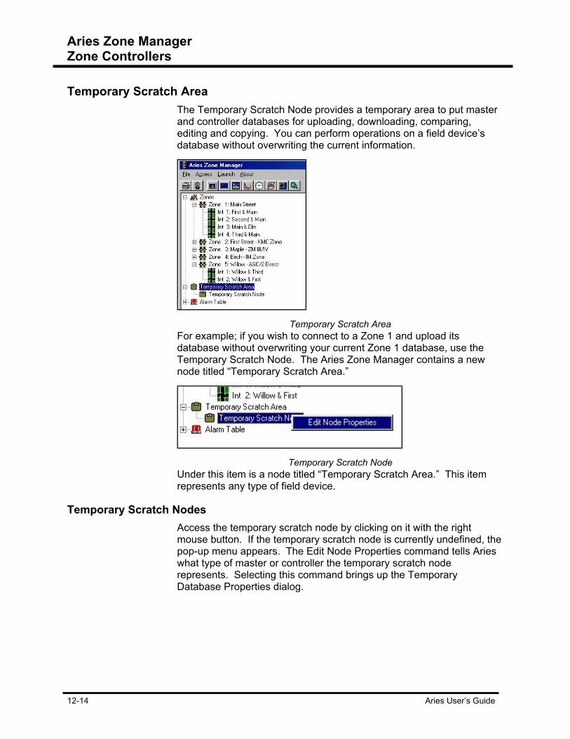
Aries Zone Manager Zone Controllers
12-14 Aries User’s Guide
Temporary Scratch Area The Temporary Scratch Node provides a temporary area to put master
and controller databases for uploading, downloading, comparing, editing and copying. You can perform operations on a field device’s database without overwriting the current information.
Temporary Scratch Area
For example; if you wish to connect to a Zone 1 and upload its database without overwriting your current Zone 1 database, use the Temporary Scratch Node. The Aries Zone Manager contains a new node titled “Temporary Scratch Area.”
Temporary Scratch Node
Under this item is a node titled “Temporary Scratch Area.” This item represents any type of field device.
Temporary Scratch Nodes Access the temporary scratch node by clicking on it with the right
mouse button. If the temporary scratch node is currently undefined, the pop-up menu appears. The Edit Node Properties command tells Aries what type of master or controller the temporary scratch node represents. Selecting this command brings up the Temporary Database Properties dialog.

Aries Zone Manager Zone Controllers
Aries User’s Guide 12-15
Temporary Database Properties dialog box
Use this dialog’s controls to enter in all of the information required to connect to each field device that Aries supports. Select the type of device at the top of the dialog, then enter in the appropriate data and press the OK button. The temporary scratch node is updated to show your definition.
Temporary Scratch Node popup menu.
For example; the temporary scratch node shown above, is now defined as an ASC/2M node for Zone 1. Clicking on this node now with the right mouse button brings up a slightly different pop-up menu.
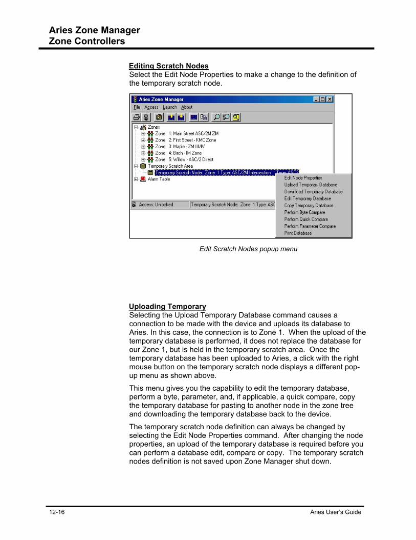
Aries Zone Manager Zone Controllers
12-16 Aries User’s Guide
Editing Scratch Nodes Select the Edit Node Properties to make a change to the definition of
the temporary scratch node.
Edit Scratch Nodes popup menu
Uploading Temporary Selecting the Upload Temporary Database command causes a
connection to be made with the device and uploads its database to Aries. In this case, the connection is to Zone 1. When the upload of the temporary database is performed, it does not replace the database for our Zone 1, but is held in the temporary scratch area. Once the temporary database has been uploaded to Aries, a click with the right mouse button on the temporary scratch node displays a different pop-up menu as shown above. This menu gives you the capability to edit the temporary database, perform a byte, parameter, and, if applicable, a quick compare, copy the temporary database for pasting to another node in the zone tree and downloading the temporary database back to the device. The temporary scratch node definition can always be changed by selecting the Edit Node Properties command. After changing the node properties, an upload of the temporary database is required before you can perform a database edit, compare or copy. The temporary scratch nodes definition is not saved upon Zone Manager shut down.

Aries Zone Manager Zone Controllers
Aries User’s Guide 12-17
Alarm Tables Alarm names are user definable and selected and stored in the Alarm
Tables.
Expanded Alarm Tree
Editing Alarm Table Names Use Zone Manager to edit any one of the 20 alarm table names.
Expand the Alarm Table tree to show the 20 names, by clicking on the plus sign to the left of the Alarm Table main node.
Edit Alarm Table Name
To edit an alarm table: 1. Move the cursor over the alarm you wish to edit. 2. Click the right-mouse button. The Edit Alarm Table Name dialog
box appears showing the current alarm name. Make any desired changes to the name and press the OK button.

Aries Zone Manager Zone Controllers
12-18 Aries User’s Guide
Keyboard Navigation If you prefer to use the keyboard over the mouse, you can move
through the Aries Zone Manager tree using the up, down, left and right arrow keys. From the currently selected tree node, use the up and down arrow keys to move the cursor up or down to the next node. If the currently selected node has child nodes, then expand them by pressing the right arrow key. Likewise, you can contract an expanded node by pressing the left arrow key. To access the currently selected node’s menu, press the return key and the node’s pop-up menu appears.
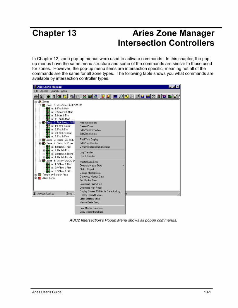
Aries User’s Guide 13-1
Chapter 13 Aries Zone Manager Intersection Controllers In Chapter 12, zone pop-up menus were used to activate commands. In this chapter, the pop-up menus have the same menu structure and some of the commands are similar to those used for zones. However, the pop-up menu items are intersection specific, meaning not all of the commands are the same for all zone types. The following table shows you what commands are available by intersection controller types.
ASC2 Intersection’s Popup Menu shows all popup commands.
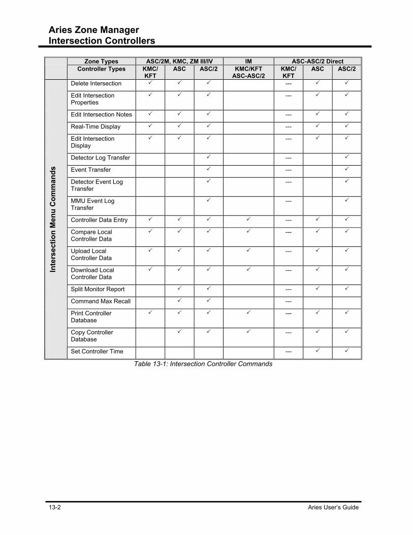
Aries Zone Manager Intersection Controllers
13-2 Aries User’s Guide
Zone Types ASC/2M, KMC, ZM III/IV IM ASC-ASC/2 Direct Controller Types KMC/
KFT ASC ASC/2 KMC/KFT
ASC-ASC/2 KMC/ KFT
ASC ASC/2
Delete Intersection ---
Edit Intersection Properties
---
Edit Intersection Notes ---
Real-Time Display ---
Edit Intersection Display
---
Detector Log Transfer ---
Event Transfer ---
Detector Event Log Transfer
---
MMU Event Log Transfer
---
Controller Data Entry ---
Compare Local Controller Data
---
Upload Local Controller Data
---
Download Local Controller Data
---
Split Monitor Report ---
Command Max Recall ---
Print Controller Database
---
Copy Controller Database
---
Inte
rsec
tion
Men
u C
omm
ands
Set Controller Time ---
Table 13-1: Intersection Controller Commands
Aries Zone Manager Intersection Controllers
Aries User’s Guide 13-3
Basic Intersection Menu functions The Intersection Node Menu is accessed by right-clicking-mouse button
when the cursor is anywhere over an intersection node. This menu contains functions which operate directly on an intersection or are related to an intersection. Each of the commands in the Intersection Node Menu is described in this section.
Deleting Intersection This command allows the deletion of the intersection nodes from the
system. Selection of this command brings up a message box asking: “Do you want to remove this intersection?” The choices are YES and NO. Selecting YES causes the selected intersection node to be removed and the Zone Manager display is updated. If there are any controller files for this intersection, they are not deleted. Selection of NO aborts the intersection deletion process; the intersection remains intact.
Editing Intersection This menu command allows you to edit the intersection information you
entered when the intersection was originally added. This dialog box appears exactly the same as the Add Intersection Node dialog (Refer to the Add Intersection Node dialog figure). However the intersection number box is disabled. Change the zone name or access codes as necessary. Changing the telephone number or bit rate depends on the intersection’s zone type. With some zone types, the telephone and bit rate fields are disabled. Intersection numbers are permanent once they are defined for an intersection. If a mistake in an intersection number was made, delete that intersection node using the procedure described previously. Then add an intersection node with the correct intersection number. Clicking on the OK button causes any changes to be incorporated and the Aries Zone Manager display is updated to reflect any changes. Clicking on Cancel causes the Edit Intersection Node dialog box to disappear and all changes are ignored.
Editing Intersection Notes This item allows you to edit and print the user notes stored for this
intersection. Selecting this menu item creates a Notes dialog box. The toolbar at the top of the dialog provides you with the capability to save any changes made to the notes and to print the notes, while providing the text cut, copy and paste functions. When editing the notes is complete, press the Close button.

Aries Zone Manager Intersection Controllers
13-4 Aries User’s Guide
Real Time Displays This menu item allows you to start an intersection display for the
selected intersection node by invoking the Zone-Intersection Display application. This application runs independently of the Zone Manager application.
Editing Intersection Displays This menu item allows you to edit a selected intersection display for by
invoking the Zone-Intersection Display application. This application runs independently of the Aries Zone Manager application.
Detector Log Transfer, Event Log Transfer and Detector Event Log Transfer These log transfers refer to information logs containing specific events,
detector information and detector event situations. During the upload process, this information appears in the Operation Progress window and is saved to the hard drive.
MMU Event Log Transfer Malfunction Management Unit (MMU) log contains controller
malfunctions and the reasons why the malfunction occurred. Selecting this command activates the Aries Communication Server to connect with the controller. Once the connection is established, the controller transmits a record of MMU events to the Aries system. The events display in the Operation Progress Window.
Controller Data Entry Like Master Controller Data Entry, Controller Data Entry accesses the
Aries Data Entry application. After selecting an intersection or intersection(s) and starting the database information appears in the Data Entry tabs. In this window, you are able to view, compare and edit master data files. On the left side of the screen, a topic list appears with topics pertaining to intersection information and programming. Some of the topics display more that one tab for that information. There are scrolling arrows to assist in viewing all the tabs and the information they contain. Depending on the intersection type, some of the tabs will be disabled. Select an item from the topic list and notice the tabs on the right change. The information from the database appears in the fields towards the right. Once you are finished changing values, you have the option to Save the file, download the information back to the controller, or close out of the file without saving the information.
Aries Zone Manager Intersection Controllers
Aries User’s Guide 13-5
Comparing Local Controller Data Selecting the Compare Local Controller Data establishes a connection
to the system and uploads data from the local controller selected. Here comparisons are made between master zone data files and new uploaded files. In the Zone command Compare Master Data there are two sub-commands of Byte and Parameter. In Compare Local Controller Data, these two sub-commands are joined by another sub-command, Quick Compare. Quick Compare allows you to run a quick compare between the master controller file and the uploaded file by comparing a 2-byte CRC value per segment.
Uploading Local Controller Data Uploading Local Controller Data is done via the Aries Communications
Server. The Server establishes a connection to the local controller’s system and uploads the local controller data. Like uploading master data, uploading local controller data shows in the Operation Progress window and also allows the options of saving, comparing or canceling the uploaded data.
Downloading Local Controller Data The Download Controller Data function establishes a connection to the
system and downloads data to the local controller. The progress of the download appears on screen.
Split Monitor Report This command brings up the Split Monitor application. In the Split
Monitor Report screens you can gather data from that intersection in report format. For more information on Split Monitor Reports, please see the Split Monitor Report chapter.
Command Max Recall Command Max Recall in the intersection only makes that intersection
force its phases to time its maximum green time. As in the Zone selection, the Command Max Recall brings up the Max Recall Time dialog box. The time amount in minutes ranges from 1-99.
Printing Controller Database This command allows you to print out a hard copy of the controller file’s
database. Click on Print Controller Database to bring up the Database Print Choice dialog box.
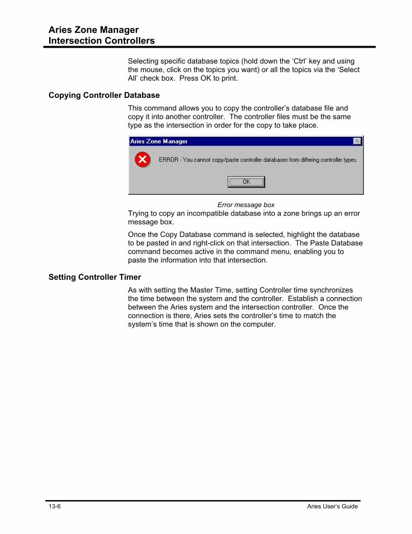
Aries Zone Manager Intersection Controllers
13-6 Aries User’s Guide
Selecting specific database topics (hold down the ‘Ctrl’ key and using the mouse, click on the topics you want) or all the topics via the ‘Select All’ check box. Press OK to print.
Copying Controller Database This command allows you to copy the controller’s database file and
copy it into another controller. The controller files must be the same type as the intersection in order for the copy to take place.
Error message box
Trying to copy an incompatible database into a zone brings up an error message box. Once the Copy Database command is selected, highlight the database to be pasted in and right-click on that intersection. The Paste Database command becomes active in the command menu, enabling you to paste the information into that intersection.
Setting Controller Timer As with setting the Master Time, setting Controller time synchronizes
the time between the system and the controller. Establish a connection between the Aries system and the intersection controller. Once the connection is there, Aries sets the controller’s time to match the system’s time that is shown on the computer.

Aries User’s Guide 14-1
Chapter 14 Aries Zone Manager Intersection Monitors Intersection Monitors (IM) are intersections monitors attached to controllers. IMs use one direct modem phone line per controller to communicate with the Aries system and each monitor is attached to a controller. Unlike other intersection types, IM intersection nodes branch out further to show the monitor and controllers as two separate nodes. With IMs, there are three active popup menus. The menu for the intersection node itself. The second menu pertains to the intersection monitor.
Intersection Monitor Pop-up Menu

Aries Zone Manager Intersection Monitors
14-2 Aries User’s Guide
While the third menu pertains to the controller attached to the monitor. As with the all pop-up menus, they appear when the intersection, the monitor or the controller nodes are highlighted and right-clicked on with the mouse.
Intersection Controller Node Pop-up Menu
In the following table, you see what commands function with which controller type. The commands are explained later in this section
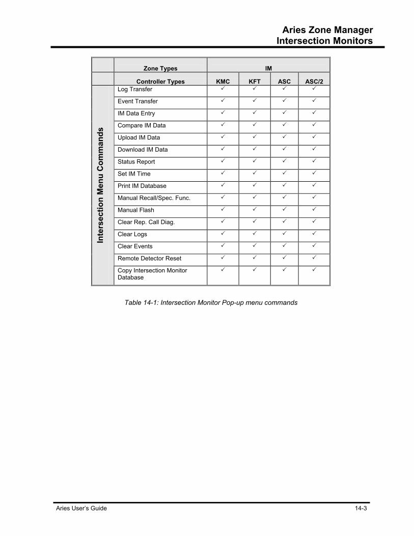
Aries Zone Manager Intersection Monitors
Aries User’s Guide 14-3
Zone Types
IM
Controller Types KMC KFT ASC ASC/2 Log Transfer
Event Transfer
IM Data Entry
Compare IM Data
Upload IM Data
Download IM Data
Status Report
Set IM Time
Print IM Database
Manual Recall/Spec. Func.
Manual Flash
Clear Rep. Call Diag.
Clear Logs
Clear Events
Remote Detector Reset
Inte
rsec
tion
Men
u C
omm
ands
Copy Intersection Monitor Database
Table 14-1: Intersection Monitor Pop-up menu commands
Aries Zone Manager Intersection Monitors
14-4 Aries User’s Guide
Log Transfers and Event Transfers Log transfers and event transfers occur using the Aries Communication
Server to establish a connection between the IM monitor and the Aries System. During the upload process this information appears in the Operation Progress window and is saved to the hard drive.
IM Data Entry and IM Controller Data Entry Select the IM Data Entry to access a DOS application window. In this
window, pressing a number indicated on the screen brings up another screen to enter or change controller information. To save changes, press F4. To exit the screen, press F1 and click on the close icon in the upper right hand side of the screen. The Controller Data Entry menu functions differently for the controllers attached to Intersection Monitors. For ASC, KMC and KF2 controllers, accessing Data Entry is the same as accessing the Data Entry for the IMs. It is done through DOS screens. If the controller attached to the IM is an ASC/2, the Data Entry screen appears and the information is accessed in the same manner as for a zone or for another intersection type.
Comparing IM Data Selecting the Compare Local Controller Data establishes a connection
to the system and uploads data from the local controller selected. Make comparisons between master zone data files and new uploaded files with this item.
Uploading IM Data Uploading IM Data is the same as uploading zone or intersection data
and is done via the Aries Communications Server. The Server establishes a connection to the local controller’s system and uploads the local controller data. The uploading procedure shows in the Operation Progress window and also allows the options of saving, comparing or canceling the uploaded data.
Downloading IM Data Downloading IM Data is the same as downloading zone or intersection
data and done via the Aries Communications Server. The Server establishes a connection to the local controller’s system and downloads the local controller data. Also, the downloading procedure shows in the Operation Progress.
Aries Zone Manager Intersection Monitors
Aries User’s Guide 14-5
Status Report There are two options for generating a status report, Complete Status
Report or Brief Status Report. Both these options use the Aries Communications Server to establish a dial-up connection and both reports are viewed in the Operations Progress Messages.
Setting IM Time Selecting the set IM time establishes a connection between the Aries
system and the IM controller. Once the connection is there, Aries sets the IM controller’s time to the system’s time as shown on the computer, synchronizing all the zones within the system.
Printing IM Database This command allows you to print out a hard copy of the IM database
files. Clicking on Print IM Database brings up the Database Print Choice dialog box. Select specific database topics (hold down the ‘Ctrl’ key and using the mouse, to select more than one topic) or all the topics via the ‘Select All’ check box. Press OK to print.
Manual Recall/Special Function Manual Recall/Special Function command recalls the phase to green
forcing a constant call. Note that special fun
Manual Flash Manual Flash is only available with an ASC/2S-IM monitor. This
command sets the intersection to flash.
Clearing Repetitive Call Diagnostic Clear Repetitive Call Diagnostic is set up in the Intersection Monitor
Data Entry window. This command clears the diagnostic itself.
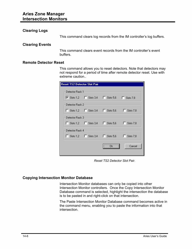
Aries Zone Manager Intersection Monitors
14-6 Aries User’s Guide
Clearing Logs This command clears log records from the IM controller’s log buffers.
Clearing Events This command clears event records from the IM controller’s event
buffers.
Remote Detector Reset This command allows you to reset detectors. Note that detectors may
not respond for a period of time after remote detector reset. Use with extreme caution..
Reset TS2 Detector Slot Pair.
Copying Intersection Monitor Database Intersection Monitor databases can only be copied into other
Intersection Monitor controllers. Once the Copy Intersection Monitor Database command is selected, highlight the intersection the database is to be pasted in and right-click on that intersection. The Paste Intersection Monitor Database command becomes active in the command menu, enabling you to paste the information into that intersection.

Aries User’s Guide 15-1
Chapter 15 Operations Scheduler The Operations Scheduler application gives you the ability to schedule zone and intersection operations to take place on a specific day, at a specific time, and to repeat this action, if desired, at a determined interval. The Operations Scheduler interface consists of a split window listing each operation’s status in the top portion and each operation’s progress as it executes appears in the lower portion of the window; a status bar at the bottom of the window and an application pull-down menu bar.
Aries Operations Scheduler window.
Once the Aries Operations Scheduler is opened, the application gears up to run or ‘scan’ for all scheduled operations. ‘Scanning’ refers to the applications looking for operations to run. Once Scheduler is activated, you are unable to create, edit, delete or disable operations, until all the scans have been completed. However, once the application is opened, there is a 30 second window where the program can suspend scanning. The Operations Scheduler window displays seven pieces of information about each operation: operational status, operation start date, operation start time, the operation’s function, operation repeat, operation final date and zone number(s).
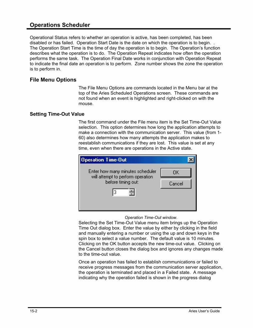
Operations Scheduler
15-2 Aries User’s Guide
Operational Status refers to whether an operation is active, has been completed, has been disabled or has failed. Operation Start Date is the date on which the operation is to begin. . The Operation Start Time is the time of day the operation is to begin. The Operation’s function describes what the operation is to do. The Operation Repeat indicates how often the operation performs the same task. The Operation Final Date works in conjunction with Operation Repeat to indicate the final date an operation is to perform. Zone number shows the zone the operation is to perform in.
File Menu Options The File Menu Options are commands located in the Menu bar at the
top of the Aries Scheduled Operations screen. These commands are not found when an event is highlighted and right-clicked on with the mouse.
Setting Time-Out Value
The first command under the File menu item is the Set Time-Out Value selection. This option determines how long the application attempts to make a connection with the communication server. This value (from 1-60) also determines how many attempts the application makes to reestablish communications if they are lost. This value is set at any time, even when there are operations in the Active state.
Operation Time-Out window.
Selecting the Set Time-Out Value menu item brings up the Operation Time Out dialog box. Enter the value by either by clicking in the field and manually entering a number or using the up and down keys in the spin box to select a value number. The default value is 10 minutes. Clicking on the OK button accepts the new time-out value. Clicking on the Cancel button closes the dialog box and ignores any changes made to the time-out value. Once an operation has failed to establish communications or failed to receive progress messages from the communication server application, the operation is terminated and placed in a Failed state. A message indicating why the operation failed is shown in the progress dialog

Operations Scheduler
Aries User’s Guide 15-3
window and also written to the status log if message logging is turned on. Refer to the sections “Viewing Operation Progress” and “Status Log Messages” for more information on status messages.
Setting Maximum Number of Concurrent Operations
A conversation is an electronic communication between Aries and the controller. The maximum number of conversations is set by selecting the Set Maximum Number of Concurrent Conversations command from the File application pull-down menu.
Maximum Conversations window.
The Operations Scheduler provides the ability to specify how many conversations are preformed at one time. If this value is set to 1, only one conversation is performed at a given time. The benefit of setting the number of concurrent conversations to one (1) is that messages from all active operations are not intermixed, providing for more readable output in the progress window. For operations to be performed concurrently, it is recommended that this value be set no greater than the number of COM ports you are using to connect to your field devices.
Printing Progress List While an operation is performing, messages regarding the operation
are displayed in the progress window. These messages are written into the progress list which is located beneath the operations list. This list is printed by selecting the Print Progress List menu item in the File menu.
Clearing Progress List The progress window maintains a list of messages detailing the
progress of each operation taking place. For permanent messages, refer to the section, Status Log Messages. When messages need to be deleted, use the Clear Progress List menu item to clear all messages from the progress list.

Operations Scheduler
15-4 Aries User’s Guide
Log Messages Operation status messages are written to an ASCII text file. This file is
named SCHEDULE.LOG and is located in the ZMLOGS sub-directory. As each operation is activated, status messages are appended to the end of the log. To disable writing messages to the log file: 1. Click the File menu item in the application pull-down menu. 2. From here you can select the item Log Messages. 3. Click on this item to cause the checkmark to appear, indicating that
message logging is enabled. To disable Log Messages, click the Log Messages menu item again.
Some of the messages shown in the Scheduler’s progress message window represent final results of the scheduled operations. The Scheduler provides a means of saving these messages in a log file through its logging capability. The logging capability is enabled/disabled through the Log Messages command under the File application pull-down menu.
Displaying Log Message Window
Log Messages window
To view the log file, select the Display Log Message Window from the File application pull-down menu. This brings up the Log Messages box containing the contents to the Scheduler log file. From this box you can print the log file or copy portions of it for pasting in another document.
Exiting Scheduler Select Exit Scheduler from the File Menu.

Operations Scheduler
Aries User’s Guide 15-5
Schedule Operation Menu Options Schedule Operation Menu Options allow you to create operations,
suspend operations and resume operations. From here, you need to suspend operations from scanning within 30 seconds of activating Operations Scheduler or you must wait until all prior and current operations have been completed before the application allows you to create, edit, disable or delete an operation.
Creating an Operation Scheduled Operations are created via the Schedule Operation menu
command. Create an operation by clicking on Create New Operation. If your system is locked you need to enter the Data Change Access Codes. The Operation Definition dialog box appears.
Operation Definition dialog box
The operation types supported by the Operations Scheduler are: Zone Master: ASC/2 Log Transfers: Time Set Status Log Event
Detector Event Detector Event MMU Event
Intersection Monitors: Other: Snap Shot Upload Log Download Event Compare Status Time Set
Auto Compare Auto Upload Auto Download Split Monitor Report
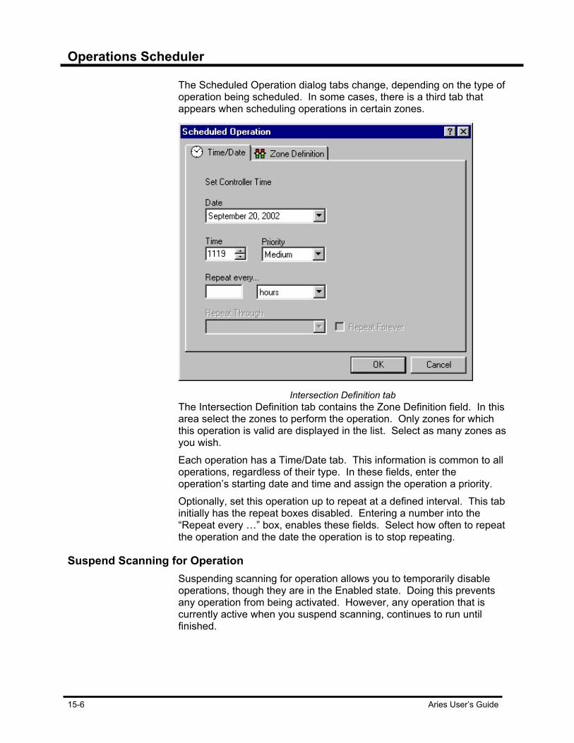
Operations Scheduler
15-6 Aries User’s Guide
The Scheduled Operation dialog tabs change, depending on the type of operation being scheduled. In some cases, there is a third tab that appears when scheduling operations in certain zones.
Intersection Definition tab
The Intersection Definition tab contains the Zone Definition field. In this area select the zones to perform the operation. Only zones for which this operation is valid are displayed in the list. Select as many zones as you wish. Each operation has a Time/Date tab. This information is common to all operations, regardless of their type. In these fields, enter the operation’s starting date and time and assign the operation a priority. Optionally, set this operation up to repeat at a defined interval. This tab initially has the repeat boxes disabled. Entering a number into the “Repeat every …” box, enables these fields. Select how often to repeat the operation and the date the operation is to stop repeating.
Suspend Scanning for Operation Suspending scanning for operation allows you to temporarily disable
operations, though they are in the Enabled state. Doing this prevents any operation from being activated. However, any operation that is currently active when you suspend scanning, continues to run until finished.
Operations Scheduler
Aries User’s Guide 15-7
To suspend operations, select the Suspend Scanning for Operations menu item in the Schedule Operation pull-down menu. Text appears in the status bar at the bottom of the application window informing you that the operational status has been “suspended.”
Resume Scanning for Operation Selecting Resume Scanning for Operation from the Schedule Operation
pull-down menu, allows operations to become active again. The status bar text is updated to indicate that the operational status is “running” and operations due to be performed have become active.
Right-Click Popup Menu Items As with other Aries applications, the Operations Scheduler utilizes right
mouse button menus. There are two right mouse menus in this application. The first is the operation specific menu. The commands available from this pop-up menu are specific to the currently selected item. In the Status column, the selected item’s text is highlighted. To access this menu, right-click the mouse when the cursor is over an operation’s status icon or status text. This menu provides you with commands to edit, delete, enable or disable this operation. How to perform these actions is detailed in the next section.
Editing, Enabling, Disabling or Deleting Operation Information Right clicking on a scheduled operation brings up a pop-up menu
containing four commands, Edit Operations, Delete Operations, Disable Operations and Enable Operations, with Disabled Operations grayed out. Unless an operation has completed is schedule or has failed, rarely are all four commands enabled at the same time. Edit Operations allows you to make changes to an already scheduled operation though the Schedule Operation window tabs. Delete Operation allows you to delete an operation. When you select to delete an operation, a message box appears, asking if you are sure you want to delete it. Choosing ‘Yes’ deletes the operation, choosing ‘No’ closes the box and the operation remains as it was. Disable Operation allows you to prevent the operation from running without deleting it. This option is useful if a monitor is going to be out-of-order for a length of time for repairs. Disable the operations prevents them from running during the repair down time. Enable Operations allows you to re-activate previously disabled operations.

Operations Scheduler
15-8 Aries User’s Guide
Operations As previously mention in the Performing Operations section, you are
unable to edit, delete, enable or disable any operation if one or more operations are in the active state. If operations are not active or have all been completed, you can edit, suspend, enable or disable any operation in the list.
Scheduling an Operation The Scheduled Operation window box reflects the zone and
intersections and operation selected in the Intersection tab. Other tabs appear in addition to the Intersection and Time/Date tabs, they are the Auto Compare tab, Options, Snapshot, Segments, Duration and Time. These tabs appear depending on the type of operation specified.
Intersection Operation Information For intersection specific operations, the Scheduled Operation contains
the Intersection Definition tab. In this tab, select the zone’s intersections the operation is scheduled for.
Intersection Tab
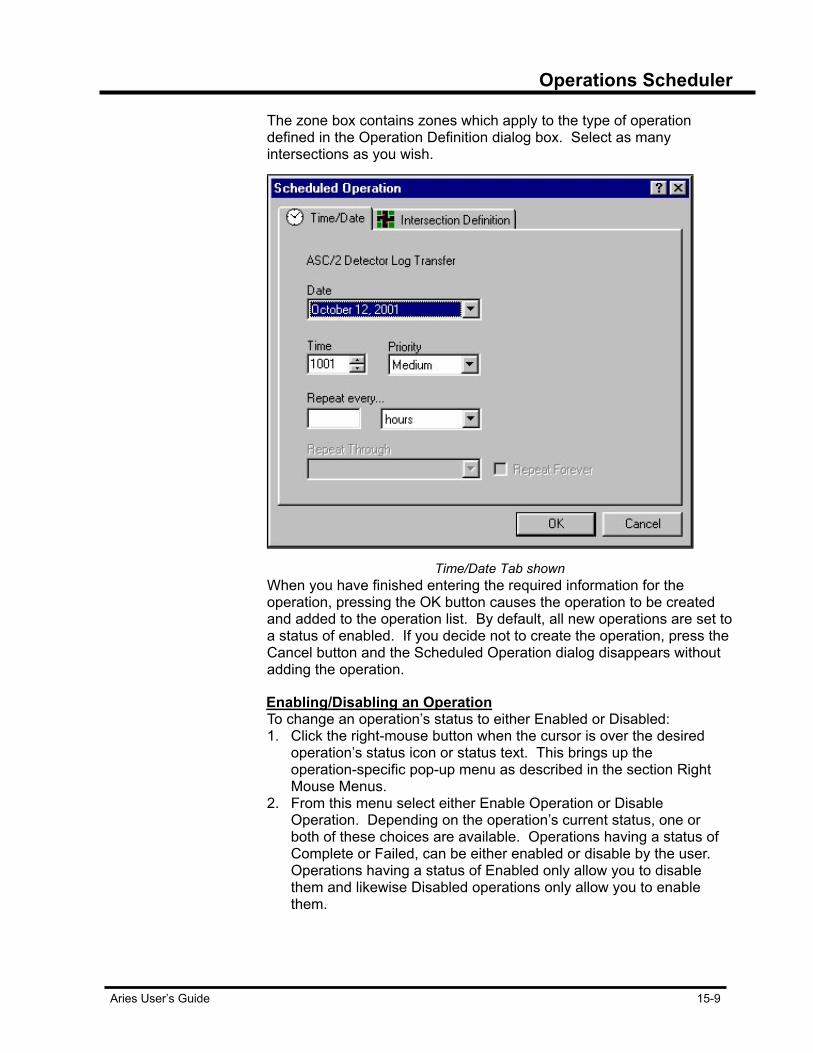
Operations Scheduler
Aries User’s Guide 15-9
The zone box contains zones which apply to the type of operation defined in the Operation Definition dialog box. Select as many intersections as you wish.
Time/Date Tab shown
When you have finished entering the required information for the operation, pressing the OK button causes the operation to be created and added to the operation list. By default, all new operations are set to a status of enabled. If you decide not to create the operation, press the Cancel button and the Scheduled Operation dialog disappears without adding the operation.
Enabling/Disabling an Operation To change an operation’s status to either Enabled or Disabled:
1. Click the right-mouse button when the cursor is over the desired operation’s status icon or status text. This brings up the operation-specific pop-up menu as described in the section Right Mouse Menus.
2. From this menu select either Enable Operation or Disable Operation. Depending on the operation’s current status, one or both of these choices are available. Operations having a status of Complete or Failed, can be either enabled or disable by the user. Operations having a status of Enabled only allow you to disable them and likewise Disabled operations only allow you to enable them.
Operations Scheduler
15-10 Aries User’s Guide
3. After enabling/disabling an operation, the operation’s status icon and status text change to reflect your change. Once enabled, an operation is performed when it becomes due. Disabled operations are never performed until they are changed to an enabled status.
Performing Operations The Operations Scheduler performs scheduled operations based upon
their status. An operation’s status is indicated by the status icon and its associated status text. An operation has five status states:
• Operation Enabled • Operation Disabled • Operation Active • Operation Complete • Operation Failed
An operation with Enabled status is ready to perform upon its scheduled date and time. A Disabled operation is one that not performed when it reaches its scheduled date and time. An Active operation is one that is currently being performed. Operations that are either Complete or Failed have been performed and are finished. At startup, the application looks through the list of operations to see if there are any with a status of either Enabled or Active. It looks for Active operations in case there were operations that were in the Active state and never completed for some reason, such as loss of power to the computer. Any operation found with an Active status is changed to an Enabled status so that it is performed again. The application performs any operations that have a start date and time older than the current date and time. After start-up has been completed and any leftover Active operations or operations with past-due start dates have started, the applications poll every 10 seconds for any operations that have become due. When an operation is found to be due for execution according to the start date and time, its status are changed from Enabled to Active, indicating that it is being performed. If several operations become due at the same time, they are performed according to the priority level which was assigned when the operation was created. When one or more operations are in the Active state, you are not allowed to create new operations or edit or delete existing operations. If you attempt any of these actions when an operation is in the Active state, a message box appears informing you that the schedule file is being used. In order for you to be able to delete or disable any leftover Active operations or past-due operations upon application start-up, the Operations Scheduler waits 30 seconds before it attempts to perform any due operations. During this time, you can delete, disable or edit any operation.
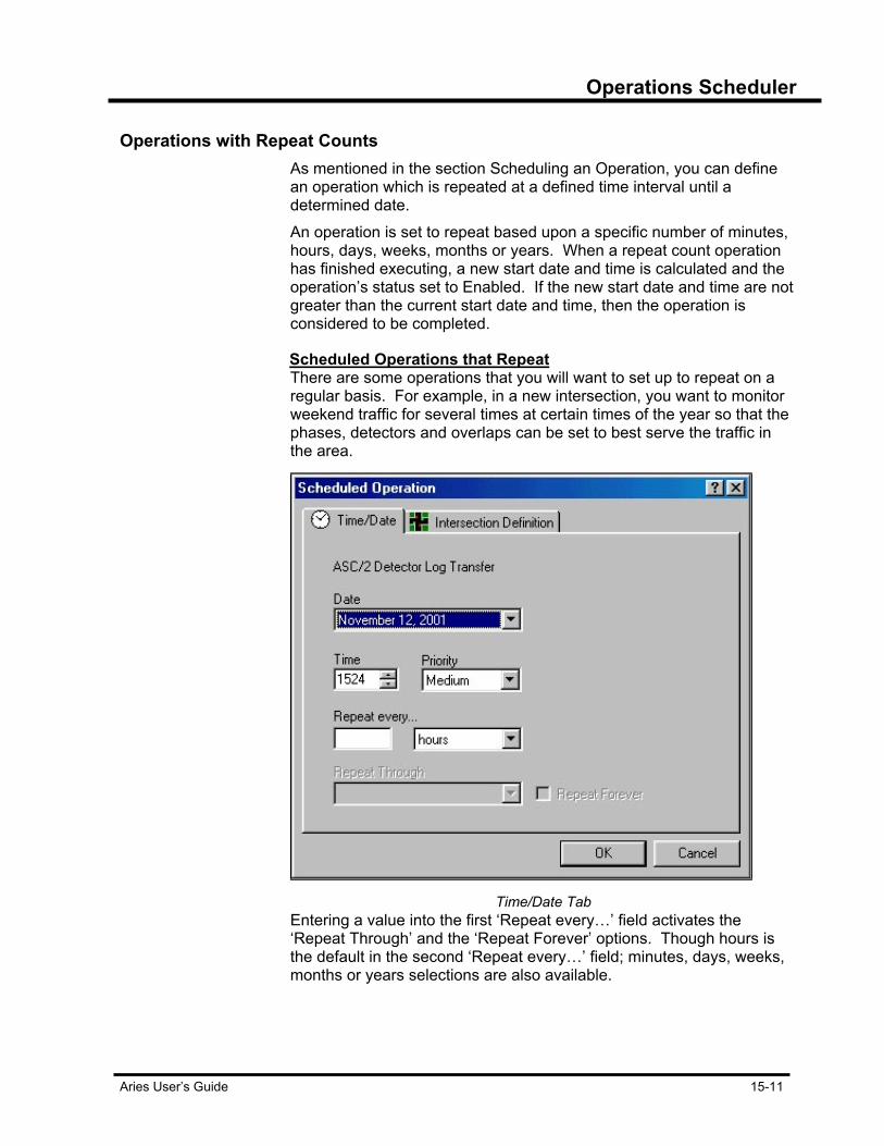
Operations Scheduler
Aries User’s Guide 15-11
Operations with Repeat Counts As mentioned in the section Scheduling an Operation, you can define
an operation which is repeated at a defined time interval until a determined date. An operation is set to repeat based upon a specific number of minutes, hours, days, weeks, months or years. When a repeat count operation has finished executing, a new start date and time is calculated and the operation’s status set to Enabled. If the new start date and time are not greater than the current start date and time, then the operation is considered to be completed.
Scheduled Operations that Repeat There are some operations that you will want to set up to repeat on a
regular basis. For example, in a new intersection, you want to monitor weekend traffic for several times at certain times of the year so that the phases, detectors and overlaps can be set to best serve the traffic in the area.
Time/Date Tab
Entering a value into the first ‘Repeat every…’ field activates the ‘Repeat Through’ and the ‘Repeat Forever’ options. Though hours is the default in the second ‘Repeat every…’ field; minutes, days, weeks, months or years selections are also available.
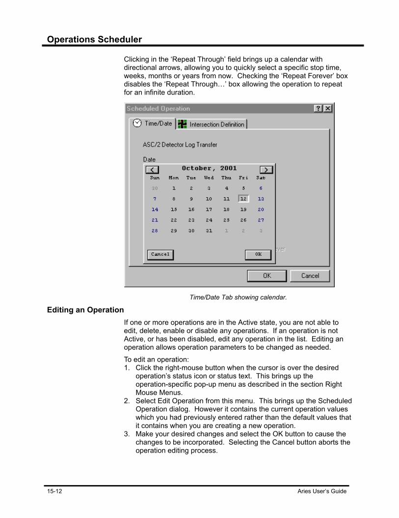
Operations Scheduler
15-12 Aries User’s Guide
Clicking in the ‘Repeat Through’ field brings up a calendar with directional arrows, allowing you to quickly select a specific stop time, weeks, months or years from now. Checking the ‘Repeat Forever’ box disables the ‘Repeat Through…’ box allowing the operation to repeat for an infinite duration.
Time/Date Tab showing calendar.
Editing an Operation If one or more operations are in the Active state, you are not able to
edit, delete, enable or disable any operations. If an operation is not Active, or has been disabled, edit any operation in the list. Editing an operation allows operation parameters to be changed as needed. To edit an operation: 1. Click the right-mouse button when the cursor is over the desired
operation’s status icon or status text. This brings up the operation-specific pop-up menu as described in the section Right Mouse Menus.
2. Select Edit Operation from this menu. This brings up the Scheduled Operation dialog. However it contains the current operation values which you had previously entered rather than the default values that it contains when you are creating a new operation.
3. Make your desired changes and select the OK button to cause the changes to be incorporated. Selecting the Cancel button aborts the operation editing process.
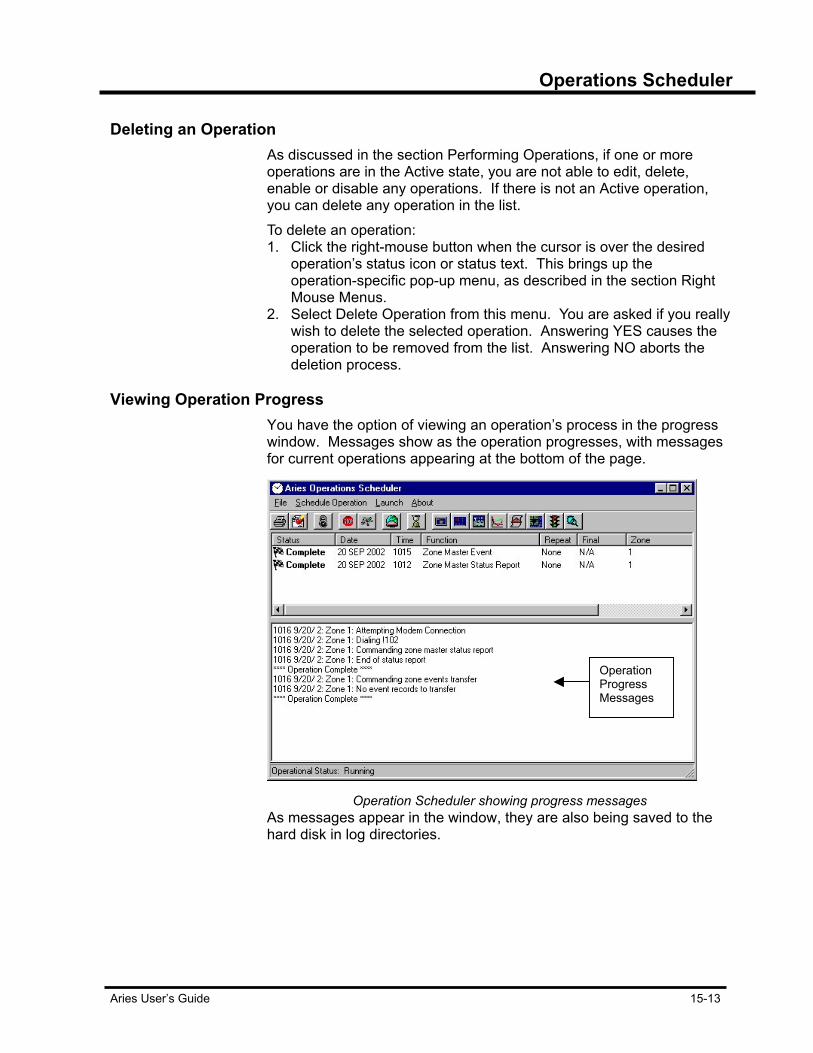
Operations Scheduler
Aries User’s Guide 15-13
Deleting an Operation As discussed in the section Performing Operations, if one or more
operations are in the Active state, you are not able to edit, delete, enable or disable any operations. If there is not an Active operation, you can delete any operation in the list. To delete an operation: 1. Click the right-mouse button when the cursor is over the desired
operation’s status icon or status text. This brings up the operation-specific pop-up menu, as described in the section Right Mouse Menus.
2. Select Delete Operation from this menu. You are asked if you really wish to delete the selected operation. Answering YES causes the operation to be removed from the list. Answering NO aborts the deletion process.
Viewing Operation Progress You have the option of viewing an operation’s process in the progress
window. Messages show as the operation progresses, with messages for current operations appearing at the bottom of the page.
Operation Scheduler showing progress messages
As messages appear in the window, they are also being saved to the hard disk in log directories.
Operation Progress Messages


Aries User’s Guide 16-1
Chapter 16 Zone and Intersection Displays Zone and intersection displays are formed by loading a background image onto the screen. These “image files” are stored in the Zmgraphs directory. Once the appropriate image file is loaded on your monitor screen, you must define what appears on the image by selecting areas on that background to represent indicators and detectors, and placing status messages in the background. After defining the display, the background, indicators and detectors and status message output, the definitions are stored in a single disk file called a “display file.”
Setting up Zone and Intersection Displays The image file used in zone and intersection displays is a PCX format
graphics file generated by the user with a tool such as Paintbrush. If the image and resulting display file is to be used with Zone Monitor IV, then a 16-color, 640 by 350 or 640 by 480 format is required. Otherwise, 16, 256 or 65536 color formats with any horizontal and vertical resolution works. The image files must be stored in the ZMGRAPHS directory.
The Zmgraphs directory
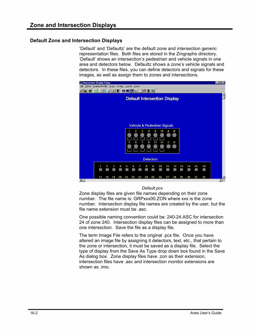
Zone and Intersection Displays
16-2 Aries User’s Guide
Default Zone and Intersection Displays ‘Default’ and ‘Defaultz’ are the default zone and intersection generic
representation files. Both files are stored in the Zmgraphs directory. ‘Default’ shows an intersection’s pedestrian and vehicle signals in one area and detectors below. Defaultz shows a zone’s vehicle signals and detectors. In these files, you can define detectors and signals for these images, as well as assign them to zones and intersections.
Default.pcx
Zone display files are given file names depending on their zone number. The file name is: GRPxxx00.ZON where xxx is the zone number. Intersection display file names are created by the user, but the file name extension must be .asc. One possible naming convention could be: 240-24.ASC for intersection 24 of zone 240. Intersection display files can be assigned to more than one intersection. Save the file as a display file. The term Image File refers to the original .pcx file. Once you have altered an image file by assigning it detectors, text, etc., that pertain to the zone or intersection, it must be saved as a display file. Select the type of display from the Save As Type drop down box found in the Save As dialog box. Zone display files have .zon as their extension, intersection files have .asc and intersection monitor extensions are shown as .imo.

Zone and Intersection Displays
Aries User’s Guide 16-3
Creating New Display Files An image file must be loaded in order to create a display file. Choose
Load from the File Menu. An Open file dialog box appears showing the default directory Zmgraphs.
Zmgraphs directory
Browse through the various images. After selecting the file to use, save the file with a new file name. File names are user determined, but keep in mind the zone and intersection numbers in the file name make it easy to access the file quickly.
Defining Symbols Vehicle and detector symbols are defined by selecting an area on the
image and associating that area with a phase or detector number. Symbol areas define phases and vehicle and pedestrian detectors. If you are drawing your intersection or zone display in another program, the areas must contain shapes of a solid color, with a solid color border completely surrounding it. These shapes must be drawn on the image before it is loaded. To begin definition: 1. Choose the Define menu item. If you are setting up a zone display,
the items are: Vehicle, Detectors, Text and Stop Defining. If you are setting up an intersection display, you also have the Pedestrian item. The vehicle symbols show the red or green status of intersection movements. In the zone display, they are referenced by controller number and phase. In the intersection display, they are referenced by phase only.
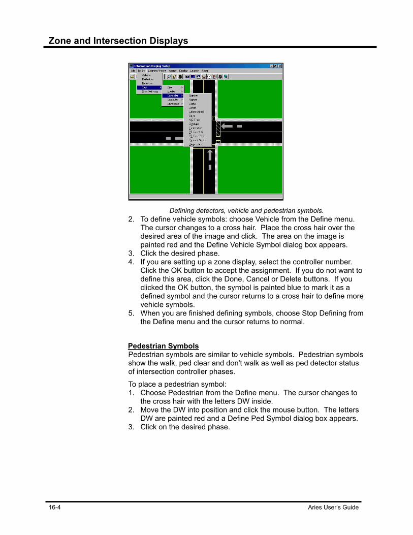
Zone and Intersection Displays
16-4 Aries User’s Guide
Defining detectors, vehicle and pedestrian symbols.
2. To define vehicle symbols: choose Vehicle from the Define menu. The cursor changes to a cross hair. Place the cross hair over the desired area of the image and click. The area on the image is painted red and the Define Vehicle Symbol dialog box appears.
3. Click the desired phase. 4. If you are setting up a zone display, select the controller number.
Click the OK button to accept the assignment. If you do not want to define this area, click the Done, Cancel or Delete buttons. If you clicked the OK button, the symbol is painted blue to mark it as a defined symbol and the cursor returns to a cross hair to define more vehicle symbols.
5. When you are finished defining symbols, choose Stop Defining from the Define menu and the cursor returns to normal.
Pedestrian Symbols Pedestrian symbols are similar to vehicle symbols. Pedestrian symbols
show the walk, ped clear and don't walk as well as ped detector status of intersection controller phases. To place a pedestrian symbol: 1. Choose Pedestrian from the Define menu. The cursor changes to
the cross hair with the letters DW inside. 2. Move the DW into position and click the mouse button. The letters
DW are painted red and a Define Ped Symbol dialog box appears. 3. Click on the desired phase.

Zone and Intersection Displays
Aries User’s Guide 16-5
4. Click the OK button to accept the assignment. If you do not want to place this symbol, click the Done, Cancel or Delete buttons. If you clicked the OK button, the symbol is painted blue to mark it as a defined symbol and the cursor returns to a cross hair to define more pedestrian symbols.
5. When you are finished defining symbols, choose Stop Defining from the Define menu and the cursor returns to normal. A larger pedestrian symbol is defined by selecting text-size from the Define menu and choosing a larger font. Text symbols show status of various items in text form. In Aries, this status is available in dialog boxes when in display mode, so placing the text symbols is optional.
Displaying Text Areas In setting up a zone display, there are only two choices in the Define -
Text menu, Size and Status. Size is used to specify the size of the characters in the status messages. The sizes available are 8 by 8, 8 by 14 and 8 by 16. “Status” allows you to place the zone status text message on the image. This status message is not used in Aries, as the information is available from the menu at display time. In setting up an intersection display file, there are five choices in the Define - Text menu. Size, is the same as in setting up a zone display. The other four items, Master, Controller, Computer and Enhanced each bring up menus of their own. Select items from these menus to place text status messages on the image. After selecting an item, move it in position by moving the mouse. When the message is in position, click the mouse button. To move the text status message after it has been set, select it again from the Define > Text menu.
Examining Symbols Use the Examine/Modify menu items to examine or modify the
properties of symbols, or to delete symbols from the display file. Choosing Examine/Modify changes the cursor to a cross hair. When clicking on the cross hair near a symbol, the symbol is painted red and an Examine Symbol dialog box appears. Change the detector number for detector symbols in zone and intersection displays. Change phase numbers for vehicle symbols in zone and intersection displays. Or change controller numbers for vehicle symbols in zone displays. Click the OK or Done buttons to accept the symbol properties as shown. Click OK, the cursor returns to a cross hair and you can examine more symbols. If you click Done, you exit the Examine mode.
Status dialog boxes are not available when using the display file with Zone Monitor IV.
Zone and Intersection Displays
16-6 Aries User’s Guide
Assigning Intersection Display Files to Intersections Before starting an intersection display, you must assign a display file to
the intersection. To assign a display file to an intersection: 1. Load the display file and choose the Assign menu item. The Select
Zone, Intersection dialog box appears. 2. Enter the desired zone and intersection. 3. Press OK.
Starting Zone and Intersection Displays Once the display files are defined and assigned to intersections, start
the zone and intersection displays. To start the Zone-Intersection Display application: 1. Select Display from the menu. The Select Zone-Intersection dialog
box appears. 2. Select the desired zone. If you are starting an intersection display,
select the desired intersection. 3. Click the OK button to start the display.
Starting Intersection Displays from Zone Map You can start an intersection display by double-clicking on a vehicle
symbol within a running zone display. The zone display is stopped and the corresponding intersection display begins in a new window.
Symbol Differences Between Aries and Zone Monitor IV The symbol area is defined differently in Aries and Zone Monitor IV. In
Aries, the symbol area is defined as an area of continuous color starting at a point selected with the mouse. In Zone Monitor IV, the symbol area is defined as the area completely bounded by the first non-matching color to the right of a point selected with the mouse. In most cases, the result is the same.
Intersection Monitor Intersection Displays Aries has the ability to show intersection displays from an intersection
monitor. These displays are very similar to intersection displays from zone masters. When creating an intersection display file for an Intersection Monitor, be sure to start with a file loaded as an IM Image. There are now a total of six file types that are loaded when Zone-Intersection Display is run in stand alone mode (i.e., not started from a zone or intersection node in Aries Zone Manager).
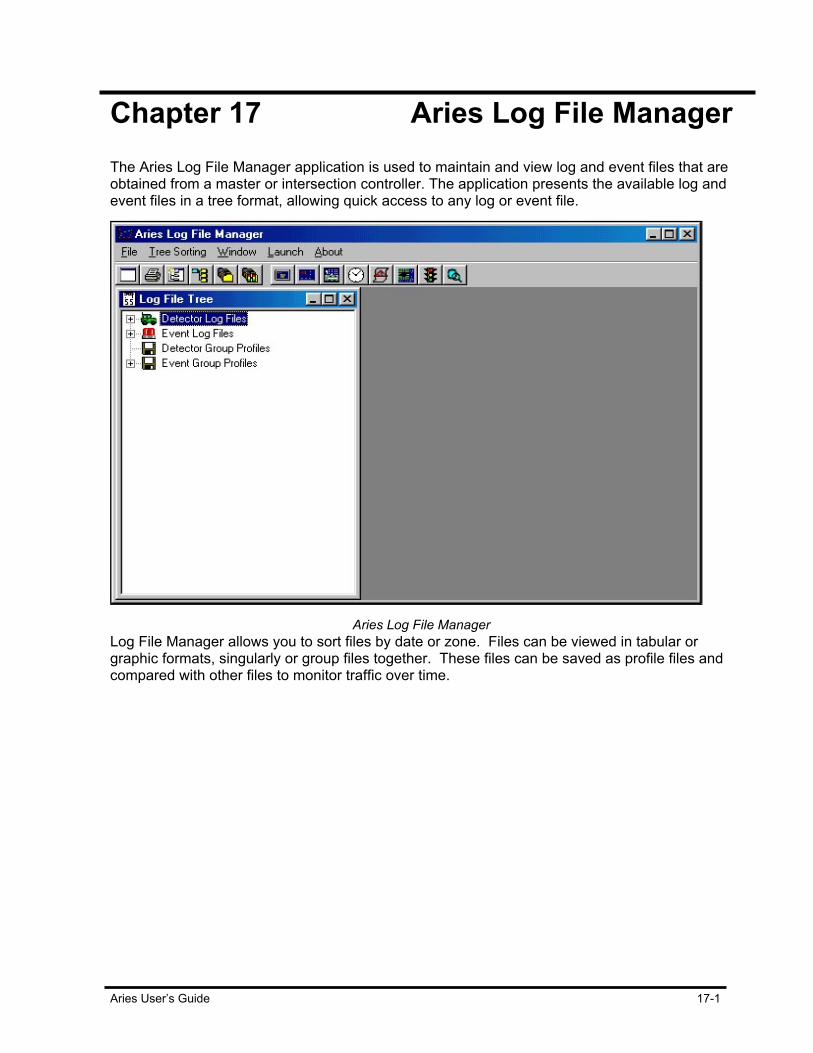
Aries User’s Guide 17-1
Chapter 17 Aries Log File Manager The Aries Log File Manager application is used to maintain and view log and event files that are obtained from a master or intersection controller. The application presents the available log and event files in a tree format, allowing quick access to any log or event file.
Aries Log File Manager
Log File Manager allows you to sort files by date or zone. Files can be viewed in tabular or graphic formats, singularly or group files together. These files can be saved as profile files and compared with other files to monitor traffic over time.

Aries Log File Manager
17-2 Aries User’s Guide
Navigating the Log File Manager Tree Each item in the Aries Log File Manager tree consists of a tree node
icon particular to the type of data the node represents, a tree node text describing the node and if the node has other nodes as children, an expand/contract box is part of the node.
Node Defined Menus The Aries Log File Manager application uses pop-up menus. When the
cursor is over a tree node and the right-mouse button is clicked, a pop-up menu appears. The items in this menu are determined by the type of node selected. The detector nodes, event nodes and date nodes have different pop-up menus. A description of these menus and an explanation of the available commands are detailed in the following sections.
Log File Tree Structure The Log File Tree has four main nodes: Detector Log Files, Event Log
Files, Detector Group Profiles and Event Group Profiles. The Detector Log Files branch of the tree provides access to detector log files obtained from an ASC/2M or ASC/2 controller. The Event Log Files branch provides access to events from an ASC/2M or ASC/2 controller. The Detector Group Profiles branch contains detector data windows which have been saved by the user. Likewise, the Event Group Profiles branch contains event data windows which have been saved by the user. Profile windows are explained in a later section.
Selecting a Tree Item The Log File Tree supports both single item selection and multiple item
selection. To select a single item in the tree, simply move the cursor over the item’s name and click the left mouse button. Multiple item selection is allowed only if the items are of the same type. For example, the items “January”, “February” and “March” represent a date type. However you would not be able to add the item “Zone 1” because it represents a zone type, not a date type. In order to select multiple items, you must select an item by moving the cursor over the item’s name and clicking with the left mouse button. Then select another item of the same type, move the cursor over the item’s name and click the left mouse button while holding down the “Ctrl” key on the keyboard.
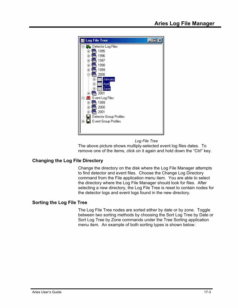
Aries Log File Manager
Aries User’s Guide 17-3
Log File Tree
The above picture shows multiply-selected event log files dates. To remove one of the items, click on it again and hold down the “Ctrl” key.
Changing the Log File Directory Change the directory on the disk where the Log File Manager attempts
to find detector and event files. Choose the Change Log Directory command from the File application menu item. You are able to select the directory where the Log File Manager should look for files. After selecting a new directory, the Log File Tree is reset to contain nodes for the detector logs and event logs found in the new directory.
Sorting the Log File Tree The Log File Tree nodes are sorted either by date or by zone. Toggle
between two sorting methods by choosing the Sort Log Tree by Date or Sort Log Tree by Zone commands under the Tree Sorting application menu item. An example of both sorting types is shown below:

Aries Log File Manager
17-4 Aries User’s Guide
Log file tree sorted by date
Log file tree sorted by zone
Log File Tree Sorted by Date. When the detector or event log file tree is sorted by date, the tree lists
information by year first, then month, date and detector. The tree lists oldest year node at the top of the screen, the most current year towards the bottom of the screen. Using this view, allows you to view compare data, detector or event first. Right-clicking on the year, month or day allows you to archive the year, month or day’s information and deletes them from the tree.
Log File Tree Sorted by Zone. Sorting by zone allows you to compare detector or event data over a
period of time. Sorting by zone, the tree lists first by zone number, then detector, then month, date and year. As with the date sorting, this view lists zones in descending order. Archiving is not an option in this view. Right-clicking on the zone, the detector and month do not respond. Right-clicking on the date brings up the detector plotting menu. This menu allows you to view different parts of the logged data in a table or chart format. There is an export selection as well. For more information, read the following paragraphs.
Viewing Detector Data Viewing the data contained in your detector log files requires a data
window. To bring up a data window, choose the New Data Window command from the File application menu item. An “empty” data window appears. The data window is considered empty when neither detector nor event data is shown and the message “No Data” is written in the middle of the window.
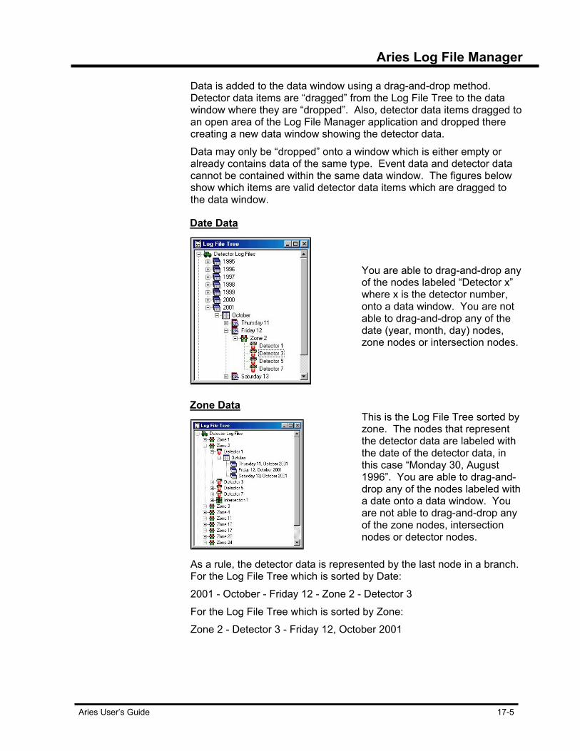
Aries Log File Manager
Aries User’s Guide 17-5
Data is added to the data window using a drag-and-drop method. Detector data items are “dragged” from the Log File Tree to the data window where they are “dropped”. Also, detector data items dragged to an open area of the Log File Manager application and dropped there creating a new data window showing the detector data. Data may only be “dropped” onto a window which is either empty or already contains data of the same type. Event data and detector data cannot be contained within the same data window. The figures below show which items are valid detector data items which are dragged to the data window.
Date Data
You are able to drag-and-drop any of the nodes labeled “Detector x” where x is the detector number, onto a data window. You are not able to drag-and-drop any of the date (year, month, day) nodes, zone nodes or intersection nodes.
Zone Data
This is the Log File Tree sorted by zone. The nodes that represent the detector data are labeled with the date of the detector data, in this case “Monday 30, August 1996”. You are able to drag-and-drop any of the nodes labeled with a date onto a data window. You are not able to drag-and-drop any of the zone nodes, intersection nodes or detector nodes.
As a rule, the detector data is represented by the last node in a branch. For the Log File Tree which is sorted by Date: 2001 - October - Friday 12 - Zone 2 - Detector 3 For the Log File Tree which is sorted by Zone: Zone 2 - Detector 3 - Friday 12, October 2001
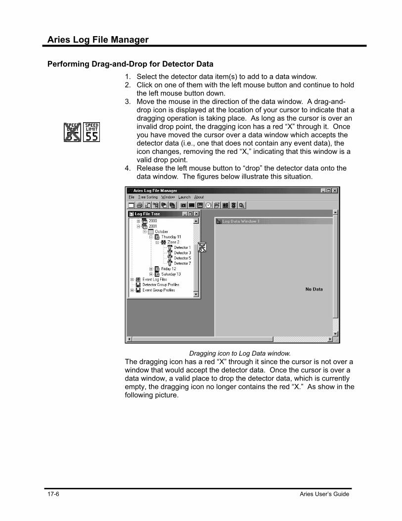
Aries Log File Manager
17-6 Aries User’s Guide
Performing Drag-and-Drop for Detector Data 1. Select the detector data item(s) to add to a data window.
2. Click on one of them with the left mouse button and continue to hold the left mouse button down.
3. Move the mouse in the direction of the data window. A drag-and-drop icon is displayed at the location of your cursor to indicate that a dragging operation is taking place. As long as the cursor is over an invalid drop point, the dragging icon has a red “X” through it. Once you have moved the cursor over a data window which accepts the detector data (i.e., one that does not contain any event data), the icon changes, removing the red “X,” indicating that this window is a valid drop point.
4. Release the left mouse button to “drop” the detector data onto the data window. The figures below illustrate this situation.
Dragging icon to Log Data window.
The dragging icon has a red “X” through it since the cursor is not over a window that would accept the detector data. Once the cursor is over a data window, a valid place to drop the detector data, which is currently empty, the dragging icon no longer contains the red “X.” As show in the following picture.
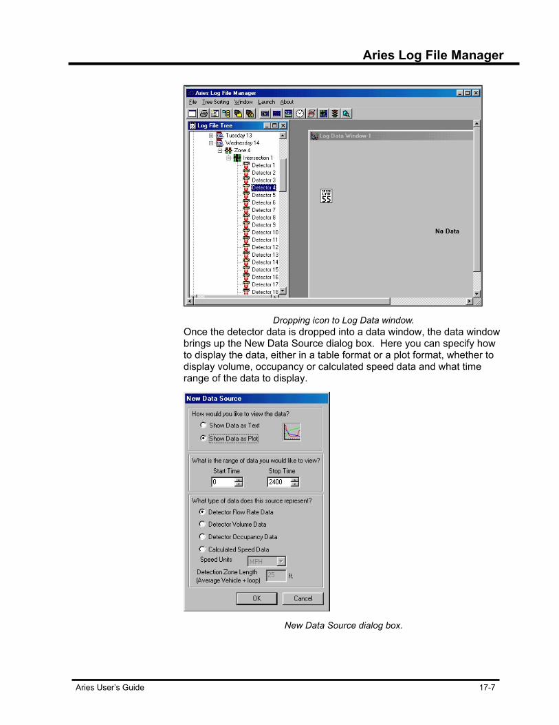
Aries Log File Manager
Aries User’s Guide 17-7
Dropping icon to Log Data window.
Once the detector data is dropped into a data window, the data window brings up the New Data Source dialog box. Here you can specify how to display the data, either in a table format or a plot format, whether to display volume, occupancy or calculated speed data and what time range of the data to display.
New Data Source dialog box.
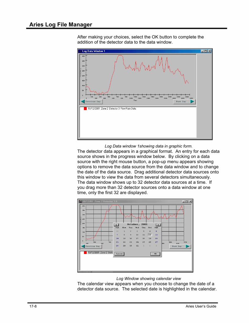
Aries Log File Manager
17-8 Aries User’s Guide
After making your choices, select the OK button to complete the addition of the detector data to the data window.
Log Data window 1showing data in graphic form.
The detector data appears in a graphical format. An entry for each data source shows in the progress window below. By clicking on a data source with the right mouse button, a pop-up menu appears showing options to remove the data source from the data window and to change the date of the data source. Drag additional detector data sources onto this window to view the data from several detectors simultaneously. The data window shows up to 32 detector data sources at a time. If you drag more than 32 detector sources onto a data window at one time, only the first 32 are displayed.
Log Window showing calendar view
The calendar view appears when you choose to change the date of a detector data source. The selected date is highlighted in the calendar.

Aries Log File Manager
Aries User’s Guide 17-9
Select a new date using the arrow keys to move the selection around the calendar. Or select the desired date with the mouse by clicking on the day with the left mouse button. Arrow buttons in the upper right and left of the calendar take you to the next and previous months. Select your desired date and press the OK button or the Enter key to remove the calendar and show the new date. Remove the calendar without selecting a date by pressing the Cancel button or Esc key.
Dragging Multiple Detectors Data Items Dragging-and-dropping several detector data items at one time to a
data window, shows a slightly different New Data Source dialog. This New Data Source dialog is displayed when you drag-and-drop multiple detector data items at one time onto a data window. There is an option to represent the data as a sum if data type is volume, or as an average if data type is occupancy or to show each detector’s data.
Log Data window showing several detector data graphs
Displaying Detector Data Shortcut A shortcut method displays detector data, bypassing the drag-and-drop
method. Right-clicking on the detector item(s) in the Log File Tree brings up the detector node pop-up menu.
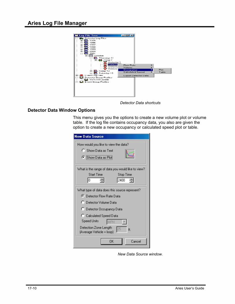
Aries Log File Manager
17-10 Aries User’s Guide
Detector Data shortcuts
Detector Data Window Options This menu gives you the options to create a new volume plot or volume
table. If the log file contains occupancy data, you also are given the option to create a new occupancy or calculated speed plot or table.
New Data Source window.
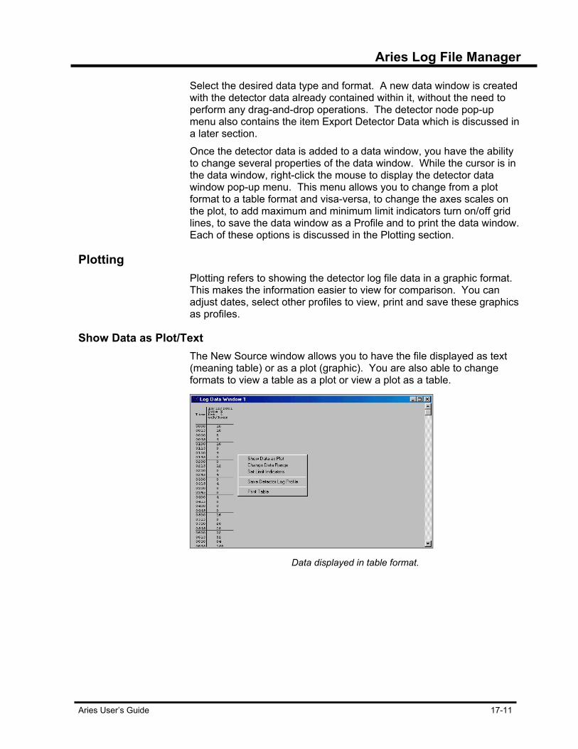
Aries Log File Manager
Aries User’s Guide 17-11
Select the desired data type and format. A new data window is created with the detector data already contained within it, without the need to perform any drag-and-drop operations. The detector node pop-up menu also contains the item Export Detector Data which is discussed in a later section. Once the detector data is added to a data window, you have the ability to change several properties of the data window. While the cursor is in the data window, right-click the mouse to display the detector data window pop-up menu. This menu allows you to change from a plot format to a table format and visa-versa, to change the axes scales on the plot, to add maximum and minimum limit indicators turn on/off grid lines, to save the data window as a Profile and to print the data window. Each of these options is discussed in the Plotting section.
Plotting Plotting refers to showing the detector log file data in a graphic format.
This makes the information easier to view for comparison. You can adjust dates, select other profiles to view, print and save these graphics as profiles.
Show Data as Plot/Text The New Source window allows you to have the file displayed as text
(meaning table) or as a plot (graphic). You are also able to change formats to view a table as a plot or view a plot as a table.
Data displayed in table format.
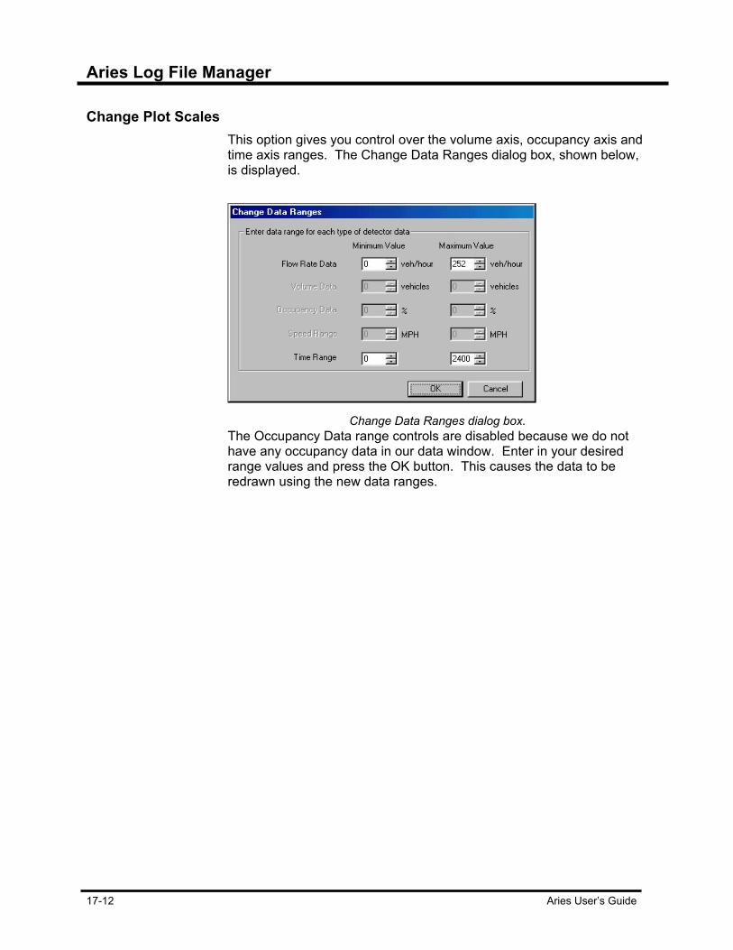
Aries Log File Manager
17-12 Aries User’s Guide
Change Plot Scales This option gives you control over the volume axis, occupancy axis and
time axis ranges. The Change Data Ranges dialog box, shown below, is displayed.
Change Data Ranges dialog box.
The Occupancy Data range controls are disabled because we do not have any occupancy data in our data window. Enter in your desired range values and press the OK button. This causes the data to be redrawn using the new data ranges.
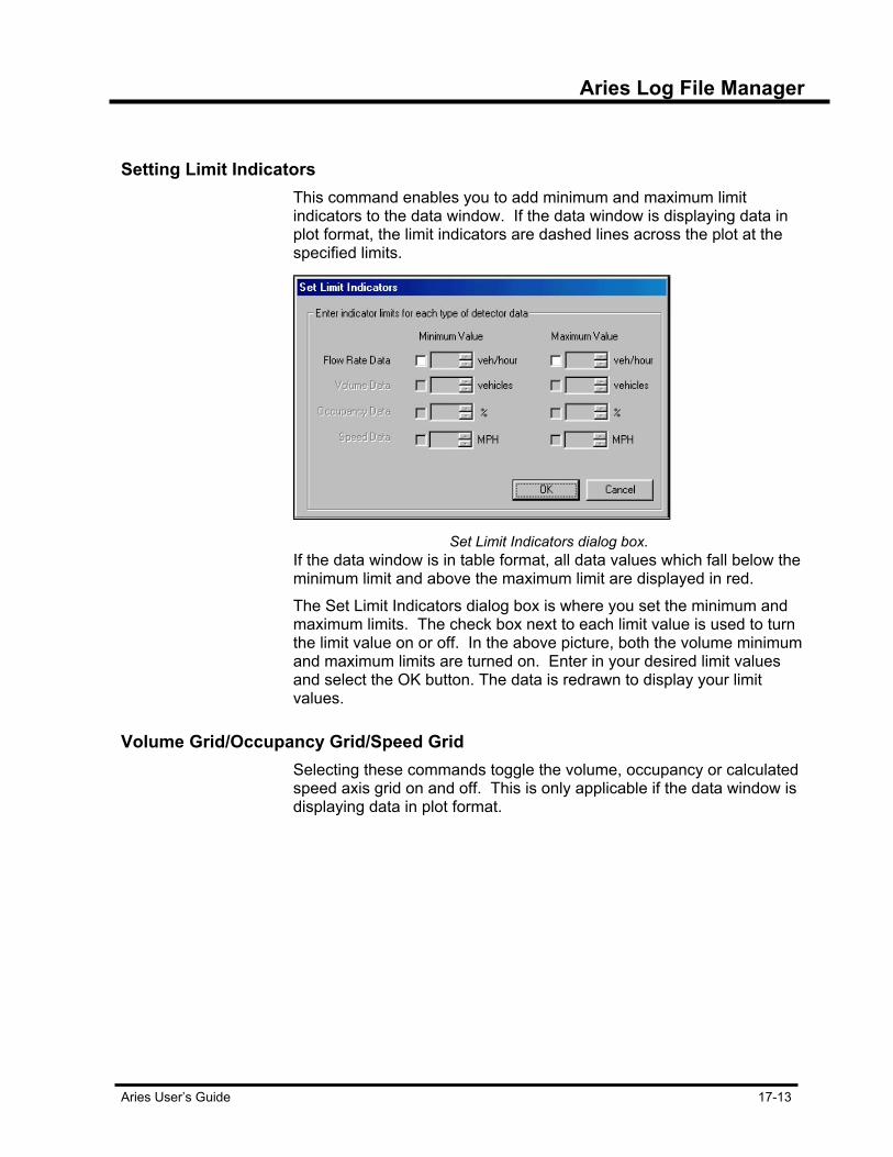
Aries Log File Manager
Aries User’s Guide 17-13
Setting Limit Indicators This command enables you to add minimum and maximum limit
indicators to the data window. If the data window is displaying data in plot format, the limit indicators are dashed lines across the plot at the specified limits.
Set Limit Indicators dialog box.
If the data window is in table format, all data values which fall below the minimum limit and above the maximum limit are displayed in red.
The Set Limit Indicators dialog box is where you set the minimum and maximum limits. The check box next to each limit value is used to turn the limit value on or off. In the above picture, both the volume minimum and maximum limits are turned on. Enter in your desired limit values and select the OK button. The data is redrawn to display your limit values.
Volume Grid/Occupancy Grid/Speed Grid Selecting these commands toggle the volume, occupancy or calculated
speed axis grid on and off. This is only applicable if the data window is displaying data in plot format.
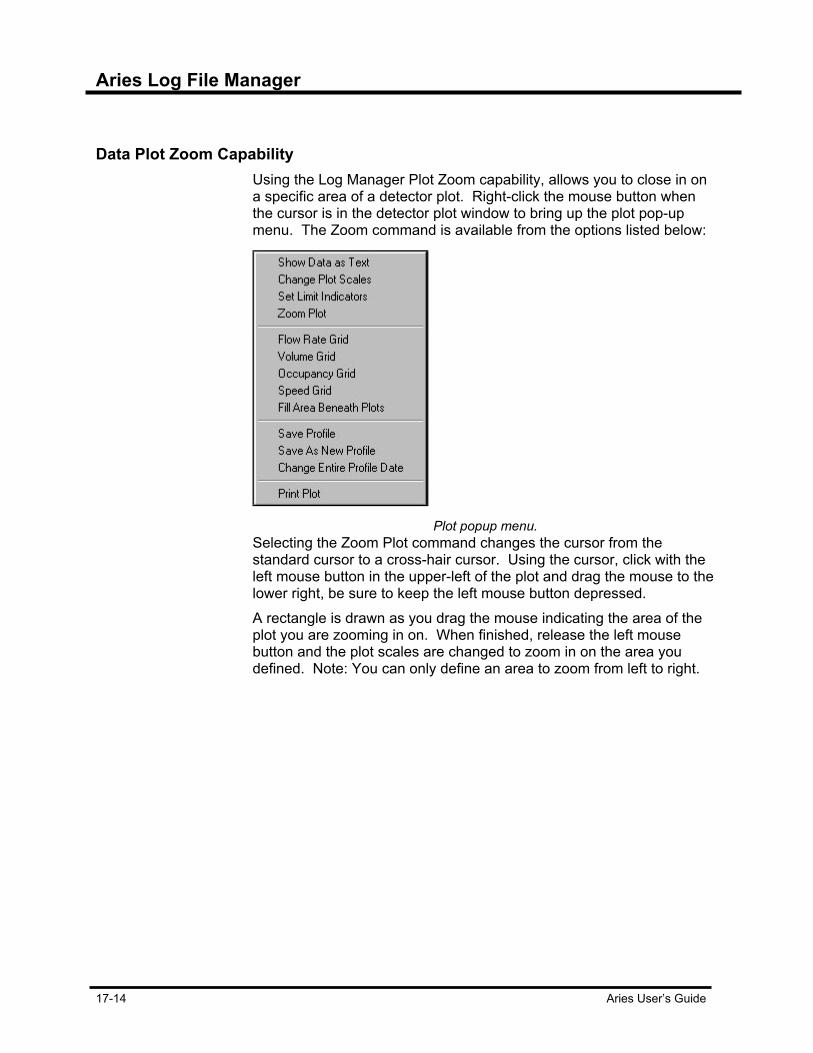
Aries Log File Manager
17-14 Aries User’s Guide
Data Plot Zoom Capability Using the Log Manager Plot Zoom capability, allows you to close in on
a specific area of a detector plot. Right-click the mouse button when the cursor is in the detector plot window to bring up the plot pop-up menu. The Zoom command is available from the options listed below:
Plot popup menu.
Selecting the Zoom Plot command changes the cursor from the standard cursor to a cross-hair cursor. Using the cursor, click with the left mouse button in the upper-left of the plot and drag the mouse to the lower right, be sure to keep the left mouse button depressed. A rectangle is drawn as you drag the mouse indicating the area of the plot you are zooming in on. When finished, release the left mouse button and the plot scales are changed to zoom in on the area you defined. Note: You can only define an area to zoom from left to right.

Aries Log File Manager
Aries User’s Guide 17-15
Log Data window showing plotted data.
To cancel the zoom plot command after you have selected it, press the Esc key and the zoom cursor is replaced by the standard cursor and the zoom function be canceled.
Saving Detector Log Profile This option allows you to save the data window for retrieval at another
time. This is particularly useful if you have a set of detectors you are always interested in and you don’t wish to create a new data window and drag your desired detectors to it each time you run the Log File Manager application. Save the data window as a Detector Log Profile and open the saved profile when you wish to view those detectors. Detector Log Profiles are detailed in a later section. Selecting this option brings up the dialog box shown in the following figure.
Detector Profile
Enter a name for the Profile and select the OK button. This saves the data window as a Profile and adds a node to the Log File Tree under the Detector Group Profiles node.
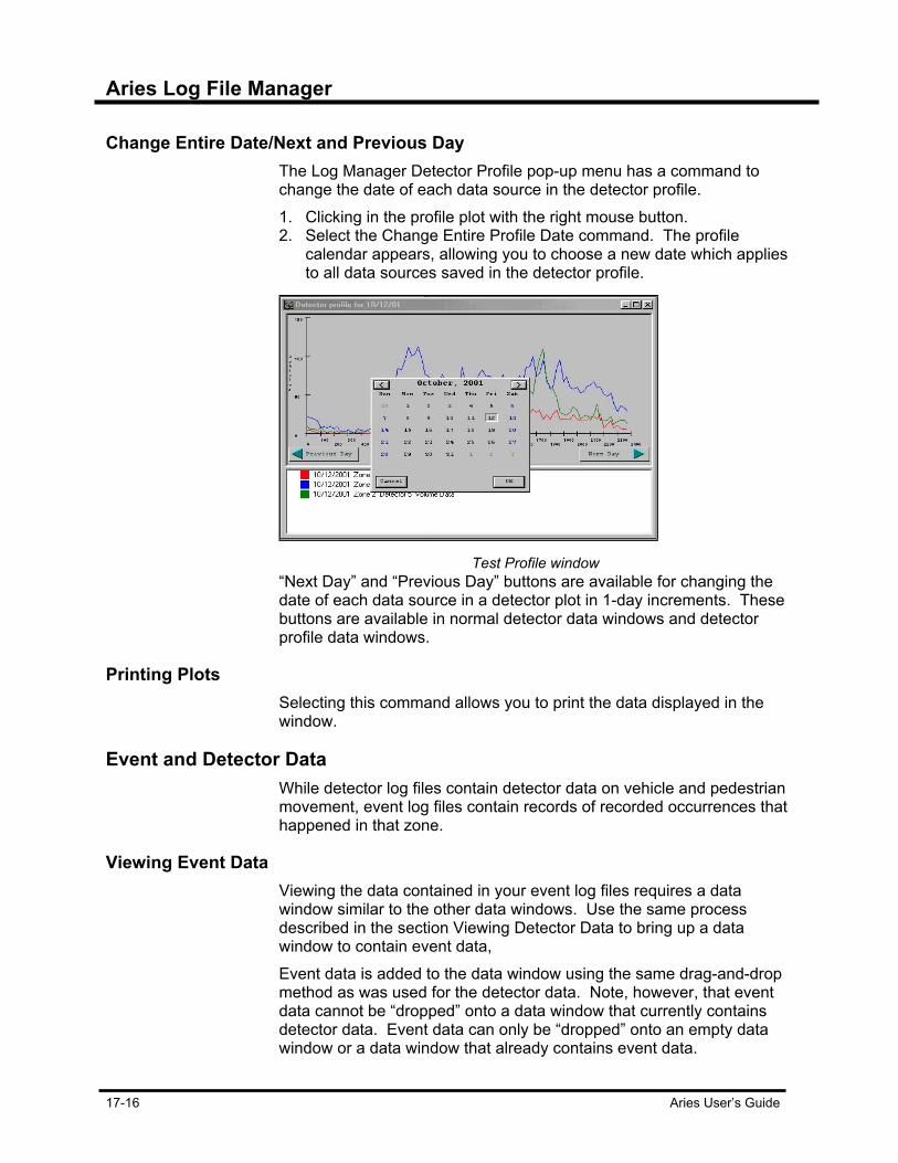
Aries Log File Manager
17-16 Aries User’s Guide
Change Entire Date/Next and Previous Day The Log Manager Detector Profile pop-up menu has a command to
change the date of each data source in the detector profile. 1. Clicking in the profile plot with the right mouse button. 2. Select the Change Entire Profile Date command. The profile
calendar appears, allowing you to choose a new date which applies to all data sources saved in the detector profile.
Test Profile window
“Next Day” and “Previous Day” buttons are available for changing the date of each data source in a detector plot in 1-day increments. These buttons are available in normal detector data windows and detector profile data windows.
Printing Plots Selecting this command allows you to print the data displayed in the
window.
Event and Detector Data While detector log files contain detector data on vehicle and pedestrian
movement, event log files contain records of recorded occurrences that happened in that zone.
Viewing Event Data Viewing the data contained in your event log files requires a data
window similar to the other data windows. Use the same process described in the section Viewing Detector Data to bring up a data window to contain event data, Event data is added to the data window using the same drag-and-drop method as was used for the detector data. Note, however, that event data cannot be “dropped” onto a data window that currently contains detector data. Event data can only be “dropped” onto an empty data window or a data window that already contains event data.
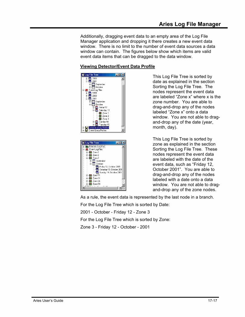
Aries Log File Manager
Aries User’s Guide 17-17
Additionally, dragging event data to an empty area of the Log File Manager application and dropping it there creates a new event data window. There is no limit to the number of event data sources a data window can contain. The figures below show which items are valid event data items that can be dragged to the data window.
Viewing Detector/Event Data Profile
This Log File Tree is sorted by date as explained in the section Sorting the Log File Tree. The nodes represent the event data are labeled “Zone x” where x is the zone number. You are able to drag-and-drop any of the nodes labeled “Zone x” onto a data window. You are not able to drag-and-drop any of the date (year, month, day).
This Log File Tree is sorted by zone as explained in the section Sorting the Log File Tree. These nodes represent the event data are labeled with the date of the event data, such as “Friday 12, October 2001”. You are able to drag-and-drop any of the nodes labeled with a date onto a data window. You are not able to drag-and-drop any of the zone nodes.
As a rule, the event data is represented by the last node in a branch. For the Log File Tree which is sorted by Date: 2001 - October - Friday 12 - Zone 3 For the Log File Tree which is sorted by Zone: Zone 3 - Friday 12 - October - 2001

Aries Log File Manager
17-18 Aries User’s Guide
Event Log Profile A profile is a data window that has been saved to disk for recall at a
later time. Event Profiles are accessed from the Event Group Profiles node. The advantage here is there is no need to continually drag-and-drop the same event nodes to a data window each time you wish to view the data, just open the profile. Once the log data window has been saved as a profile, the profile name appears in the title bar of the window. You may drag-and-drop event data sources into them or remove event data sources from them. Right-clicking on the Event Profile window brings up a pop-up menu. This menu is identical to the one that appears in the Event Data Windows Options, but it has two new command:
• Save profile – saves the profile after changes have been made.
• Save as new profile – saves the profile under a new name.
Performing Drag-and-Drop for Event Data Drag-and-drop for event data is done in the same manner as was drag-
and-drop for detector data. Refer to the section Performing Drag-and-Drop for detector data. Once you have dropped the event data onto a data window, the Event Filter dialog box appears as shown below. The Event Filter dialog box is divided up into several “tabs”. Using these tabs, you can select which event types you wish to include in the data window and which types to filter out.

Aries Log File Manager
Aries User’s Guide 17-19
Event Filter Window
Choose the “Select All Event Types” box if you do not desire to filter out any event types. You also have the option to filter events by the time they occurred. Enter your desired event time range in the Start Time and Stop Time boxes on the Select All Events tab. Shown below is the data window after an event data source has been dropped onto it and the event filter defined.
Log Data Window

Aries Log File Manager
17-20 Aries User’s Guide
Event Data Window Options Change event data filter specifications once the data is added to a
window. While the cursor is in the data window, right-click the mouse to display the event data window pop-up menu. This menu allows you to show the event sources, save the window as an event profile, toggle the event filter tree and event filter report header and to print the event data. Each of these options is discussed below.
Showing Event Sources Selecting this command brings up the Data Sources dialog box, shown
below.
Data Source window.
This list contains an entry for each event data source contained in the data window. To remove any of the event data sources, move the cursor over the line which contains the data source to be removed and right-click the mouse. A pop-up menu appears showing the command Remove Event Source. To change the date of the event source: 1. Right-click the mouse on the desired source and select the
command Change Date of Event Source. The calendar view appears.
2. Choose a new date for the event source. 3. Close the Data Sources dialog by pressing the Close button and the
event source is re-filtered using your new specifications.
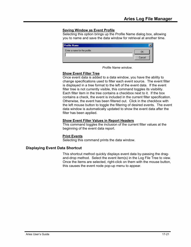
Aries Log File Manager
Aries User’s Guide 17-21
Saving Window as Event Profile Selecting this option brings up the Profile Name dialog box, allowing
you to name and save the data window for retrieval at another time.
Profile Name window.
Show Event Filter Tree Once event data is added to a data window, you have the ability to
change specifications used to filter each event source. The event filter is displayed in a tree format to the left of the event data. If the event filter tree is not currently visible, this command toggles its visibility. Each filter item in the tree contains a checkbox next to it. If the box contains a check, the event is included in the current filter specification. Otherwise, the event has been filtered out. Click in the checkbox with the left mouse button to toggle the filtering of desired events. The event data window is automatically updated to show the event data after the filter has been applied.
Show Event Filter Values in Report Headers This command toggles the inclusion of the current filter values at the
beginning of the event data report.
Print Events Selecting this command prints the data window.
Displaying Event Data Shortcut This shortcut method quickly displays event data by-passing the drag-
and-drop method. Select the event item(s) in the Log File Tree to view. Once the items are selected, right-click on them with the mouse button, this causes the event node pop-up menu to appear.
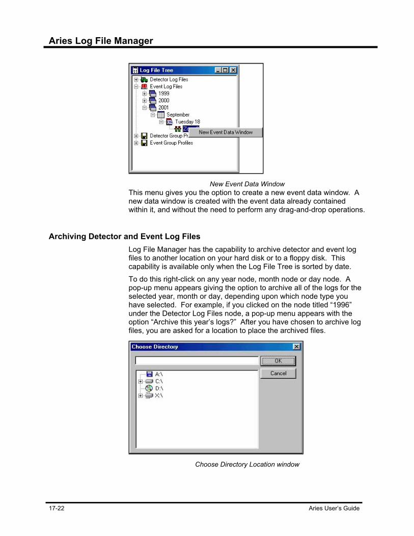
Aries Log File Manager
17-22 Aries User’s Guide
New Event Data Window
This menu gives you the option to create a new event data window. A new data window is created with the event data already contained within it, and without the need to perform any drag-and-drop operations.
Archiving Detector and Event Log Files Log File Manager has the capability to archive detector and event log
files to another location on your hard disk or to a floppy disk. This capability is available only when the Log File Tree is sorted by date. To do this right-click on any year node, month node or day node. A pop-up menu appears giving the option to archive all of the logs for the selected year, month or day, depending upon which node type you have selected. For example, if you clicked on the node titled “1996” under the Detector Log Files node, a pop-up menu appears with the option “Archive this year’s logs?” After you have chosen to archive log files, you are asked for a location to place the archived files.
Choose Directory Location window

Aries Log File Manager
Aries User’s Guide 17-23
Select the OK button, the archive process begins. A message appears, stating that any log files that currently exist at the destination location may be overwritten and the option to continue or cancel the archive process. The log files are archived to the destination directory and the progress is displayed.
Archive message box
When all the files have been archived, you are given the option to delete the original logs. If you select yes, the logs are removed from the current log directory and from the Log File Tree.
Progress Window Copy Capability The Log Manager Event Report window, the Zone Manager manual
command progress windows and batch operations progress window support standard Windows copy capability.
Copying Capability in the Event data window.
Click and hold down the left mouse button while dragging the mouse to highlight the text you wish to copy. When the desired text has been highlighted, release the left mouse button and press the Ctrl-C keyboard combination to perform a “copy” of the highlighted text. The copied text is placed into the Windows Clipboard and is pasted into any document which supports the Windows Paste function.

Aries Log File Manager
17-24 Aries User’s Guide
Exporting Detector Data The Aries Log File Manager provides you with the capability to export
the data of one or several detectors to a user named ASCII file which can then be imported by MathCad, Excel or similar spreadsheet pro-grams. The Displaying Detector Data Shortcut section described how to access the Export Detector Data command. After selecting this com-mand, the Data Export dialog box asks you whether you wish to export the volume or occupancy data for the selected detector.
Data Export dialog box
Once you select the type of data to export, you are prompted for a name for the exported file. The Choose Exported File Name dialog box allows you to enter an exported file name. It suggests a name for you which is made up of the date, zone and intersection of the detector. Once you have entered a file name, select the Save button to export the detector data.
Choose Exported File Name dialog box
The detector data exported to the ASCII file is formatted into columns with one column representing one detector’s data. Each column is separated from the others by a space. To import this data into a Microsoft Excel spreadsheet, open the data file from within Excel. The Text Import Wizard guides you through importing the detector data. Select “Delimited” for the data type and check “Space” as the delimiter, then select “General” as the Column Data Format. Press the “Finish” button to complete the import process.

Aries Log File Manager
Aries User’s Guide 17-25
To import the detector data into MathCad requires the use of the READPRN MathCad function for reading in structured data from an ASCII file. Refer to the MathCad help file for the proper usage of this feature.


Aries User’s Guide 18-1
Chapter 18 Data Entry
Aries Data Entry As mentioned in previous chapters, the Aries Data Entry application is used to view and edit the databases and in performing some batch operations. Data files are accessed through the Data Entry screen. Once the Data Entry application is activated, a zone or intersection monitor needs to be chosen from the Data Entry Selection screen.
Zone and Intersection Data Entry Selection window
After selecting the Data Entry application, you are asked to select a database you wish to load. A Data Entry Selection screen appears, displaying zone and intersections. All of them containing items for all of your defined zones and intersections. Choose the desired zone or intersection and press the OK button. The Data Topic List appears in the left side of the Aries Data Entry screen and contains entries for groups of data contained within the database. Some of the lists may be disabled as they are zone and intersection type specific, and may not apply to the zone or intersection already selected from the Data Entry Selection screen. Once the topic selection is made, the appropriate data displays in the Data Entry Area and is available for editing. If there is a large quantity of data for a particular data type, the Data Entry Area may contain several tabs to further group the data into functional areas.
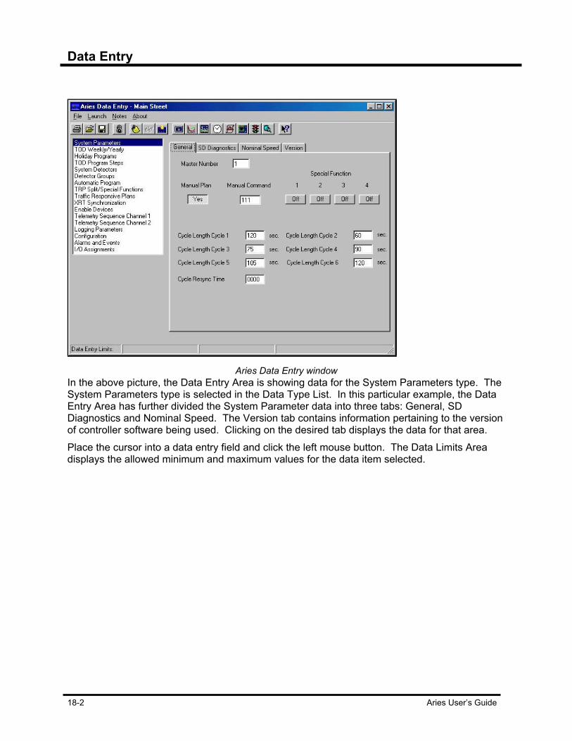
Data Entry
18-2 Aries User’s Guide
Aries Data Entry window
In the above picture, the Data Entry Area is showing data for the System Parameters type. The System Parameters type is selected in the Data Type List. In this particular example, the Data Entry Area has further divided the System Parameter data into three tabs: General, SD Diagnostics and Nominal Speed. The Version tab contains information pertaining to the version of controller software being used. Clicking on the desired tab displays the data for that area. Place the cursor into a data entry field and click the left mouse button. The Data Limits Area displays the allowed minimum and maximum values for the data item selected.
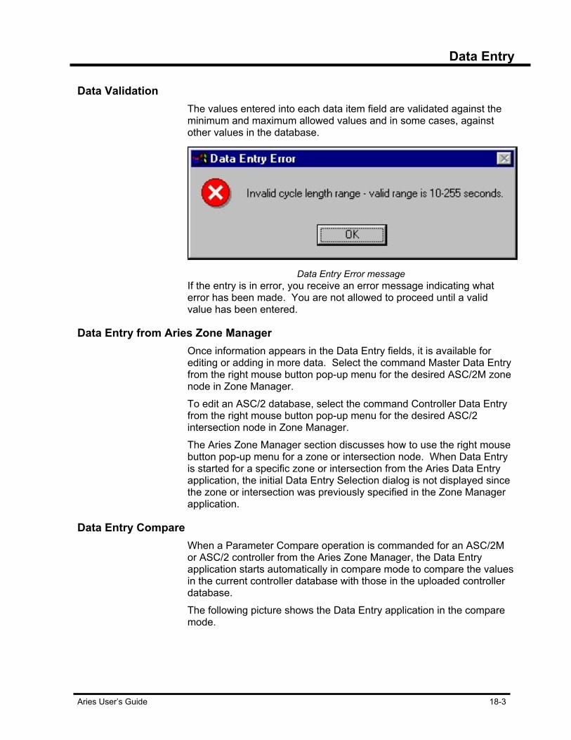
Data Entry
Aries User’s Guide 18-3
Data Validation The values entered into each data item field are validated against the
minimum and maximum allowed values and in some cases, against other values in the database.
Data Entry Error message
If the entry is in error, you receive an error message indicating what error has been made. You are not allowed to proceed until a valid value has been entered.
Data Entry from Aries Zone Manager Once information appears in the Data Entry fields, it is available for
editing or adding in more data. Select the command Master Data Entry from the right mouse button pop-up menu for the desired ASC/2M zone node in Zone Manager. To edit an ASC/2 database, select the command Controller Data Entry from the right mouse button pop-up menu for the desired ASC/2 intersection node in Zone Manager. The Aries Zone Manager section discusses how to use the right mouse button pop-up menu for a zone or intersection node. When Data Entry is started for a specific zone or intersection from the Aries Data Entry application, the initial Data Entry Selection dialog is not displayed since the zone or intersection was previously specified in the Zone Manager application.
Data Entry Compare When a Parameter Compare operation is commanded for an ASC/2M
or ASC/2 controller from the Aries Zone Manager, the Data Entry application starts automatically in compare mode to compare the values in the current controller database with those in the uploaded controller database. The following picture shows the Data Entry application in the compare mode.
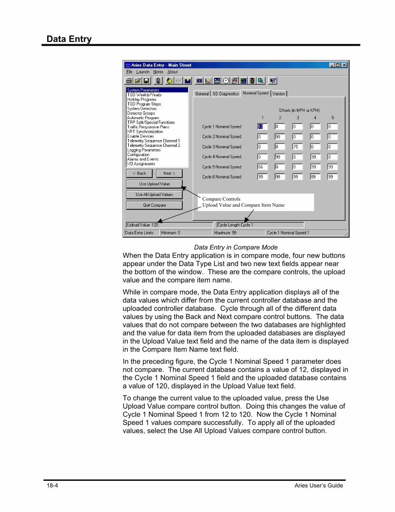
Data Entry
18-4 Aries User’s Guide
Data Entry in Compare Mode
When the Data Entry application is in compare mode, four new buttons appear under the Data Type List and two new text fields appear near the bottom of the window. These are the compare controls, the upload value and the compare item name. While in compare mode, the Data Entry application displays all of the data values which differ from the current controller database and the uploaded controller database. Cycle through all of the different data values by using the Back and Next compare control buttons. The data values that do not compare between the two databases are highlighted and the value for data item from the uploaded databases are displayed in the Upload Value text field and the name of the data item is displayed in the Compare Item Name text field. In the preceding figure, the Cycle 1 Nominal Speed 1 parameter does not compare. The current database contains a value of 12, displayed in the Cycle 1 Nominal Speed 1 field and the uploaded database contains a value of 120, displayed in the Upload Value text field. To change the current value to the uploaded value, press the Use Upload Value compare control button. Doing this changes the value of Cycle 1 Nominal Speed 1 from 12 to 120. Now the Cycle 1 Nominal Speed 1 values compare successfully. To apply all of the uploaded values, select the Use All Upload Values compare control button.
Compare Controls Upload Value and Compare Item Name

Data Entry
Aries User’s Guide 18-5
Editing Zone-Intersection Notes The Aries Data Entry application provides access to the Zone-
Intersection notes file for the particular zone or intersection database being edited. This is the same capability as discussed in the Aries Zone Manager application. From the Notes application menu item, select the Edit Zone-Intersection Notes option. The Notes dialog box appears, allowing you to save any information about the zone or intersection you desire.
The Notes window
The toolbar at the top of the dialog provides you with the capability to save any changes you make to the notes, to print the notes and the functions of text cut, copy and paste. When you have finished editing the notes, press the Close button.
Saving the Database Once you have completed editing the database, save your changes by
selecting the Save Data File command from the File application menu item. Other options Load Data File and Close Data File. Load Data File closes the current file, prompting you to save it if you have made any changes and ask you which database you wish to open next. The Close Data File option closes the current file, prompting you to save any changes you may have made.
Printing the Database Print the contents of the database by selecting the Print option from the
File application menu item. This brings up the Data File Print Choices dialog box.

Data Entry
18-6 Aries User’s Guide
Data File Print Choices window
This dialog contains the same list of groups as the Data Type List. Choose which items you wish to print or click on the Select All box to print the entire database. To select multiple items, hold down the “Ctrl” key while clicking on the items. Select the OK button to print the database.
Downloading Database to Controller Download the controller database to the controller directly from the
Data Entry application. Select the Download Data File option from the File application menu item. The Operation Progress box is displayed. This box contains progress messages for the download operation you are performing. Press the button labeled Start to begin the database download. When the download is complete, press the Close button to remove the Operation Progress box.
Enhanced Keyboard Navigation for ASC/2 and ASC/2M Data Entry
Up and down cursor keys move focus to particular fields above and below the current field. The cursor also moves to the control with the focus, when the focus is changed in this way. There is a menu item in the file menu titled “Right - Left Arrow Key Configuration.” If this is set to “Data Entry Navigation,” then the right and left cursor keys move focus to parameter fields on the right or left of the current field.

Data Entry
Aries User’s Guide 18-7
ASC/2-ASC/2M Parameter Help Aries has data entry parameter help for ASC/2 and ASC/2M. To get
help on a particular parameter, click on the context sensitive help button in the tool bar. Then, click in the parameter field. A window appears with information about that field is displayed.
Help pop-up box
To dismiss the help window, simply click anywhere with the mouse button and the window is removed.


Aries User’s Guide 19-1
Chapter 19 Aries Communications Server The Aries Communications Server (the Comm Server) is the backbone of the Aries system. Comm Server runs behind the scenes whenever an operation is performed in the Aries Zone Manager, Data Entry, Aries Operations Scheduler or any of the other applications and communications to a zone or intersection is necessary. The Communications Server is responsible for establishing a data connection with the remote device either via a modem or a direct connection, communicating with the remote device and then directing any data back to the requesting application. Most of the time, the user is unaware of the operation of the Communications Server.
Communications Server The Comm Server application has a multiple-document interface that
allows you to view several data windows at once. These windows are the Status Report Window, the Systems Event Window and the Logs Window. Any combination of these windows may be open at any time by selecting the appropriate command from the Window application menu item. Each window may be positioned and sized independently of the others.
Aries Communication Server
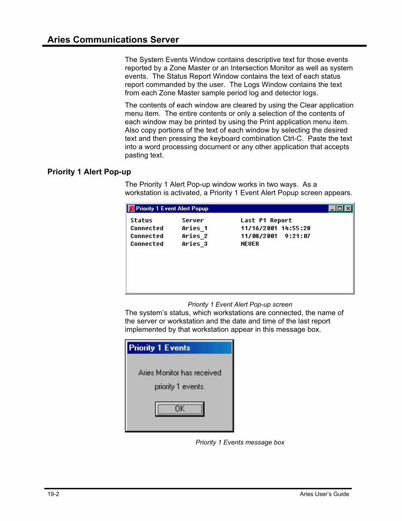
Aries Communications Server
19-2 Aries User’s Guide
The System Events Window contains descriptive text for those events reported by a Zone Master or an Intersection Monitor as well as system events. The Status Report Window contains the text of each status report commanded by the user. The Logs Window contains the text from each Zone Master sample period log and detector logs. The contents of each window are cleared by using the Clear application menu item. The entire contents or only a selection of the contents of each window may be printed by using the Print application menu item. Also copy portions of the text of each window by selecting the desired text and then pressing the keyboard combination Ctrl-C. Paste the text into a word processing document or any other application that accepts pasting text.
Priority 1 Alert Pop-up The Priority 1 Alert Pop-up window works in two ways. As a
workstation is activated, a Priority 1 Event Alert Popup screen appears.
Priority 1 Event Alert Pop-up screen
The system’s status, which workstations are connected, the name of the server or workstation and the date and time of the last report implemented by that workstation appear in this message box.
Priority 1 Events message box

Aries Communications Server
Aries User’s Guide 19-3
The Priority 1 Events window shows the workstation’s name in the box’s title bar. Several Priority 1 Events window appear on screen with different names to let you know which workstation has received the event notice.
Communications Channel In order for the Communications Server to communicate with a device,
a communications channel (also referred to as a com channel) has to be configured. A channel is a path for communications.
Channel Configuration window
The Communications Server supports up to 16 channels. To begin configuring a channel, select the Setup application menu item. The Channel Configuration dialog is displayed. This dialog box displays a list of the currently defined channels. To remove a channel, select the channel in the list and press the Remove button. To insert a new channel, press the Insert button. You are prompted for a channel number between 1 and 16. After choosing a valid channel number, the channel configuration properties dialog is displayed allowing you to edit parameters specific to the channel.

Aries Communications Server
19-4 Aries User’s Guide
Channel Configuration
Channel Configuration’s Port tab
Port Tab The Port tab allows you to specify values for the following: Port Number – the port that the channel communicates with the system device. It must be dedicated to the channel, meaning you cannot have the same port defined for more than one channel. If you enter a 0 for the port number, the channel is disabled. Bit Rate - If this is a direct-connect channel, this is bit rate that is used for communications. If this is a modem-connect channel, this is the initial bit rate used to initialize the modem. Data Bits - The number of data bits per frame. Parity - Parity mode for the channel. Stop Bits - Number of stop bits per frame.

Aries User’s Guide 19-5
Modem Tab Fixed Bit Rate - This is used for modems that support speed buffering.
If your modem supports speed buffering, check this to utilize that capability.
Modem Ini. - The initialization command for the modem if the channel is set to modem-connect. Ignored if the channel is set to direct-connect.
Channel Configuration’s Modem tab
Phone Number Dialing Prefix
Located in the Channel Configuration’s Modem tab, Dialing Prefix is a text box that allows you to set a dialing prefix value and a comma should your telecommunications system have that option.
For example, with some companies, you must dial the number 9 to access an outside phone line. Entering in the number nine, followed by a comma (9,) accomplishes that.

Aries Communications Server
19-6 Aries User’s Guide
Zones Tab
The Zones tab lets you specify which zones the channel connects with. If you wish to use this channel to communicate with any zone, check the Use For Any Zone option. Otherwise, select specific zones by selecting them from the available list.
Channel Configuration’s Zone tab
The Zones tab lists all the zones that are possible in the Aries system. If you need to select multiple zones, hold down the Ctrl key and click on the zones with the mouse. Select OK to apply the selection or Cancel to Exit the Configuration screen without applying any of the changes.

Aries Communications Server
Aries User’s Guide 19-7
Options Tab
Channel Configuration’s Options tab
The Options tab is where you designate the type of communication channel and the mode in which the channel operates. Communication Type is either Direct or Modem. Set the type to Direct if the device is connected directly to the channel. Set to Modem if a modem is used to communicate with the device. There are three choices for channel mode: Call Exclusive, Monitor Exclusive, and Choose Call Exclusive if you wish to use this channel only for the purpose of calling out to a device and not to receive calls from the device. Choose Monitor Exclusive if you wish to use this channel only for the purpose of answering calls from the device and not for calling out to the device. Select the Any option if you wish to use this channel to both place and receive calls to the device. When the Zone Number Verification box is checked, the zone number of all communications requests is verified with the zone number of the Zone Master. If they are different, the communications connection fails. If the Zone Number Verification box is not checked, an error message is displayed, but the connection is established.
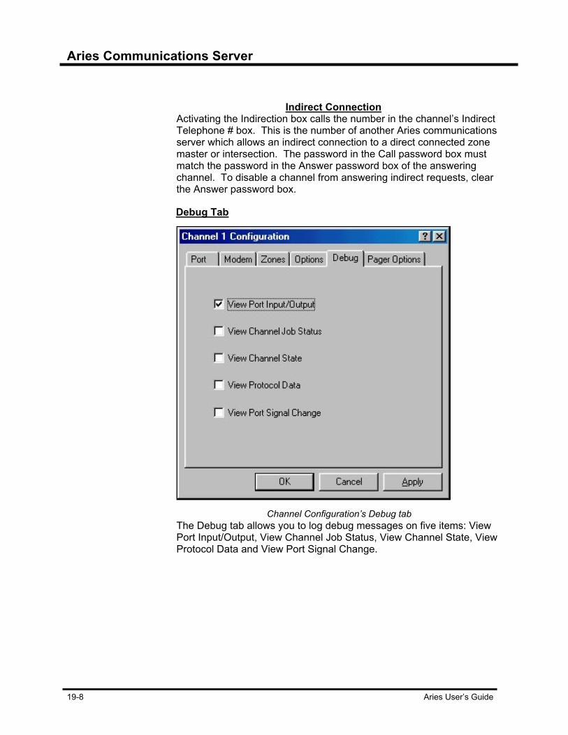
Aries Communications Server
19-8 Aries User’s Guide
Indirect Connection
Activating the Indirection box calls the number in the channel’s Indirect Telephone # box. This is the number of another Aries communications server which allows an indirect connection to a direct connected zone master or intersection. The password in the Call password box must match the password in the Answer password box of the answering channel. To disable a channel from answering indirect requests, clear the Answer password box.
Debug Tab
Channel Configuration’s Debug tab
The Debug tab allows you to log debug messages on five items: View Port Input/Output, View Channel Job Status, View Channel State, View Protocol Data and View Port Signal Change.
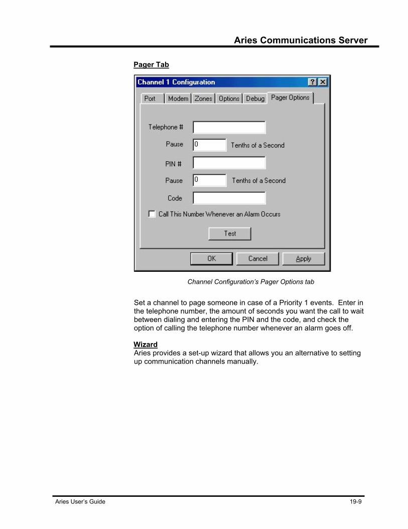
Aries Communications Server
Aries User’s Guide 19-9
Pager Tab
Channel Configuration’s Pager Options tab
Set a channel to page someone in case of a Priority 1 events. Enter in
the telephone number, the amount of seconds you want the call to wait between dialing and entering the PIN and the code, and check the option of calling the telephone number whenever an alarm goes off.
Wizard Aries provides a set-up wizard that allows you an alternative to setting
up communication channels manually.
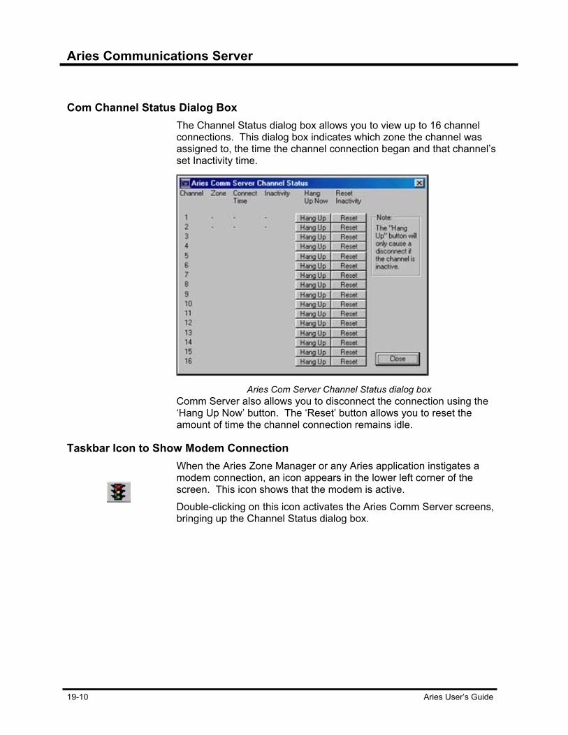
Aries Communications Server
19-10 Aries User’s Guide
Com Channel Status Dialog Box The Channel Status dialog box allows you to view up to 16 channel
connections. This dialog box indicates which zone the channel was assigned to, the time the channel connection began and that channel’s set Inactivity time.
Aries Com Server Channel Status dialog box
Comm Server also allows you to disconnect the connection using the ‘Hang Up Now’ button. The ‘Reset’ button allows you to reset the amount of time the channel connection remains idle.
Taskbar Icon to Show Modem Connection When the Aries Zone Manager or any Aries application instigates a
modem connection, an icon appears in the lower left corner of the screen. This icon shows that the modem is active. Double-clicking on this icon activates the Aries Comm Server screens, bringing up the Channel Status dialog box.
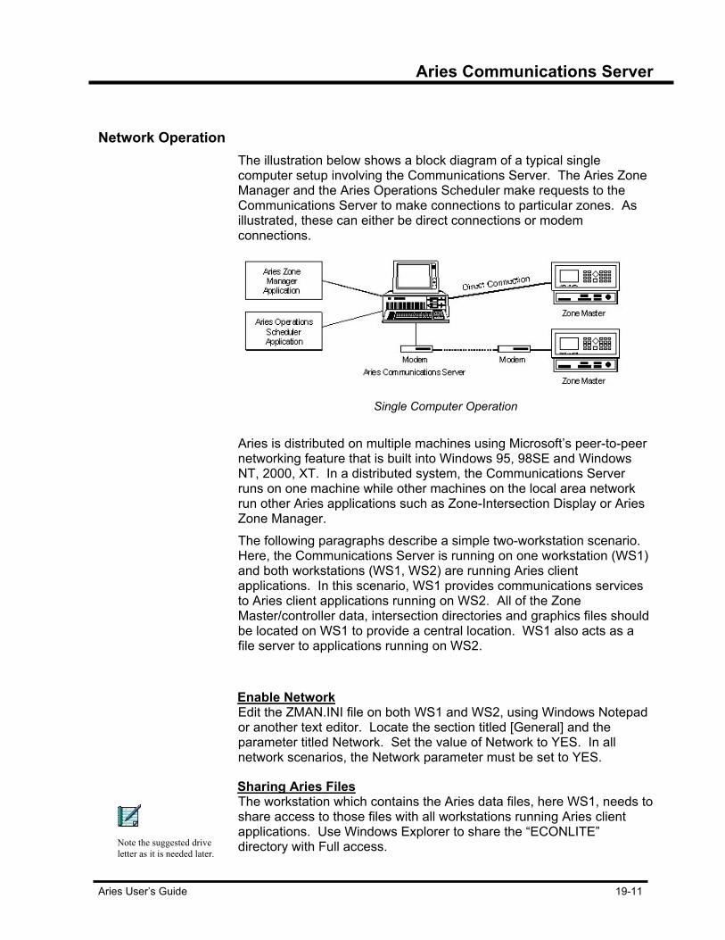
Aries Communications Server
Aries User’s Guide 19-11
Network Operation The illustration below shows a block diagram of a typical single
computer setup involving the Communications Server. The Aries Zone Manager and the Aries Operations Scheduler make requests to the Communications Server to make connections to particular zones. As illustrated, these can either be direct connections or modem connections.
Single Computer Operation
Aries is distributed on multiple machines using Microsoft’s peer-to-peer
networking feature that is built into Windows 95, 98SE and Windows NT, 2000, XT. In a distributed system, the Communications Server runs on one machine while other machines on the local area network run other Aries applications such as Zone-Intersection Display or Aries Zone Manager. The following paragraphs describe a simple two-workstation scenario. Here, the Communications Server is running on one workstation (WS1) and both workstations (WS1, WS2) are running Aries client applications. In this scenario, WS1 provides communications services to Aries client applications running on WS2. All of the Zone Master/controller data, intersection directories and graphics files should be located on WS1 to provide a central location. WS1 also acts as a file server to applications running on WS2.
Enable Network Edit the ZMAN.INI file on both WS1 and WS2, using Windows Notepad
or another text editor. Locate the section titled [General] and the parameter titled Network. Set the value of Network to YES. In all network scenarios, the Network parameter must be set to YES.
Sharing Aries Files The workstation which contains the Aries data files, here WS1, needs to
share access to those files with all workstations running Aries client applications. Use Windows Explorer to share the “ECONLITE” directory with Full access.
Note the suggested drive letter as it is needed later.

Aries Communications Server
19-12 Aries User’s Guide
Sharing Communications Server Services On workstation WS1, edit the file SHARE.INI in the “ARIES” directory.
If this file does not already exist, create it using Window’s Notepad or another text editor. The SHARE.INI file is a list of computer names that client applications scan when requesting data from the Communications Server. An example entry in the list would look like: [Zone1] SystemName=WS1 This would tell the client application to request zone 1 data from the communications server running on the computer named “WS1.” Add entries to this list for all zones to be accessed over the network.
Redirect Data Directories In order for the client applications running on WS2 to access the data
files located on WS1, the data directories need to be redirected to their location on WS1.
Two-Computer Operation
First, connect or map the shared directories on WS1 using the Windows Explorer. Using File Manager, in this example, select the “ECONLITE” directory. Select the “Map network drive” command from the “Tools” menu. Check the “Reconnect at logon” box and press “OK.”

Aries Communications Server
Aries User’s Guide 19-13
Map Network Drive window
Edit the ZMAN. INI file on WS2. Locate the section titled [Directories]. Add the following five parameters under the [Directories] heading. If the parameters are already there, delete them first or change them as follows: ZMDBASE=d:\ZMDBASE ZMLOGS=d:\ZMLOGS ZMGRAPHS=d:\ZMGRAPHS ZMEVENT=d:\SYSEVENT SHARE PROFILE=d:\ARIES\SHARE.INI Replace the letter “d” before the “:” in the above values with the drive letter entered in the “Map Network Drive” dialog box.
Remote Aries Operation It is possible to operate Aries over a remote connection. For this
purpose, remote computing software must be used. Econolite has tested Aries remote computing using pcAnywhere™ by Symantec. In the remote computing situation, one computer is running Aries and another computer, which does not have Aries installed on it, calls in and utilizes Aries running on the first computer. Both computers must have the remote computing software installed. The machine running Aries acts as a remote computing host. Refer to the documentation for the particular remote computing package you are using as to how to setup a computer as a host. Once the computer is setup as a host, it is ready to receive a call from the remote computer. On the remote computer, use the remote computing software to connect to the host. Once again, refer to your documentation as to how to perform this function. The remote computer calls the host and a connection is established. The remote computer operator has access to the host computer as if the operator were sitting in front of the host computer. Please note that this scenario results in decreased performance, particularly in areas such as scrolling window contents and displaying pop-up menus.
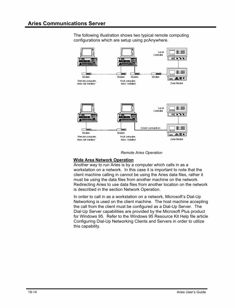
Aries Communications Server
19-14 Aries User’s Guide
The following illustration shows two typical remote computing configurations which are setup using pcAnywhere.
Remote Aries Operation
Wide Area Network Operation Another way to run Aries is by a computer which calls in as a
workstation on a network. In this case it is important to note that the client machine calling in cannot be using the Aries data files, rather it must be using the data files from another machine on the network. Redirecting Aries to use data files from another location on the network is described in the section Network Operation. In order to call in as a workstation on a network, Microsoft’s Dial-Up Networking is used on the client machine. The host machine accepting the call from the client must be configured as a Dial-Up Server. The Dial-Up Server capabilities are provided by the Microsoft Plus product for Windows 95. Refer to the Windows 95 Resource Kit Help file article Configuring Dial-Up Networking Clients and Servers in order to utilize this capability.
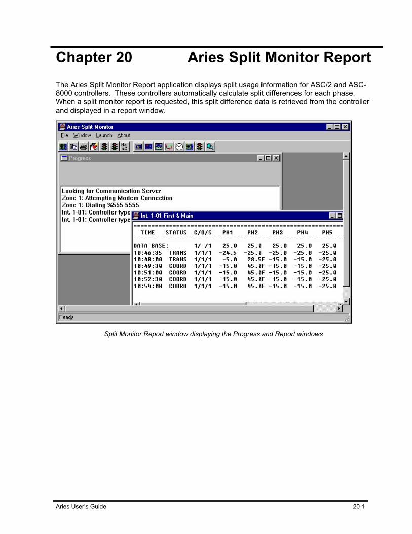
Aries User’s Guide 20-1
Chapter 20 Aries Split Monitor Report The Aries Split Monitor Report application displays split usage information for ASC/2 and ASC-8000 controllers. These controllers automatically calculate split differences for each phase. When a split monitor report is requested, this split difference data is retrieved from the controller and displayed in a report window.
Split Monitor Report window displaying the Progress and Report windows

Aries Split Monitor Report
20-2 Aries User’s Guide
Split Monitor Window The Split Monitor Report application contains one Progress Window
which displays messages about the connection to the controller and one or more Report Windows, one for each split monitor report that has been requested. Once each controller cycle, the report is updated with a split report record which consists of the time at the controller, the status of the controller, the cycle/offset/split command in effect at the controller and split differences for each phase. Possible status value descriptions: COORD - Coordinated and in sync TRANS - Transitioning or not in sync FREE - Not coordinated FLASH - Not coordinated - in flash NIC-C - Non Interconnected Coordination - in sync NIC-T - Non Interconnected Coordination - not in sync Split differences are actuallminus programmed splits at the controller in percent. If the split difference is positive, the phase has timed longer than the programmed split. If the split difference is negative, the phase has not timed it allocated split. If the phase is forced off, an “F” is appended to the end of the difference value.
Starting a Report To start a split monitor report:
1. Select the “Load Intersection” option from the “File” menu item. Choose an intersection to report on.
2. Select the desired intersection from the list. A Report Window appears with the name of the intersection in the title bar.
3. In order to begin gathering split data for the report, select the “Begin Data Acquisition” option from the “File” menu item. A data connection is established with the controller. A split report record is added for each cycle to the Report Window.
The Aries Split Monitor application provides a multiple document interface which allows several split monitor reports for intersections of the same zone to be open at the same time. Each split monitor report is shown in a separate Report Window.
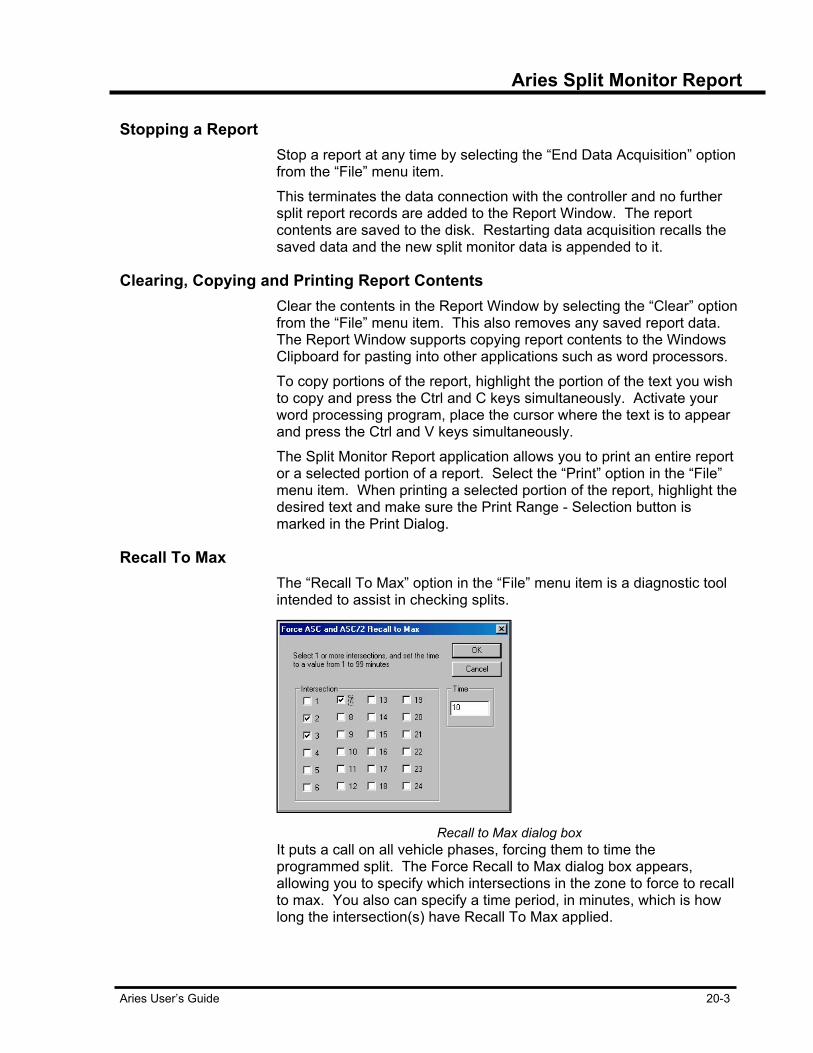
Aries Split Monitor Report
Aries User’s Guide 20-3
Stopping a Report Stop a report at any time by selecting the “End Data Acquisition” option
from the “File” menu item. This terminates the data connection with the controller and no further split report records are added to the Report Window. The report contents are saved to the disk. Restarting data acquisition recalls the saved data and the new split monitor data is appended to it.
Clearing, Copying and Printing Report Contents Clear the contents in the Report Window by selecting the “Clear” option
from the “File” menu item. This also removes any saved report data. The Report Window supports copying report contents to the Windows Clipboard for pasting into other applications such as word processors. To copy portions of the report, highlight the portion of the text you wish to copy and press the Ctrl and C keys simultaneously. Activate your word processing program, place the cursor where the text is to appear and press the Ctrl and V keys simultaneously. The Split Monitor Report application allows you to print an entire report or a selected portion of a report. Select the “Print” option in the “File” menu item. When printing a selected portion of the report, highlight the desired text and make sure the Print Range - Selection button is marked in the Print Dialog.
Recall To Max The “Recall To Max” option in the “File” menu item is a diagnostic tool
intended to assist in checking splits.
Recall to Max dialog box
It puts a call on all vehicle phases, forcing them to time the programmed split. The Force Recall to Max dialog box appears, allowing you to specify which intersections in the zone to force to recall to max. You also can specify a time period, in minutes, which is how long the intersection(s) have Recall To Max applied.
Aries Split Monitor Report
20-4 Aries User’s Guide
Manual or Scheduled Operation Split monitor reports are initiated manually for a specific intersection from
the Aries Zone Manager application or scheduled for automatic operation using the Aries Operations Scheduler. Refer to the sections for each of these applications for further information.
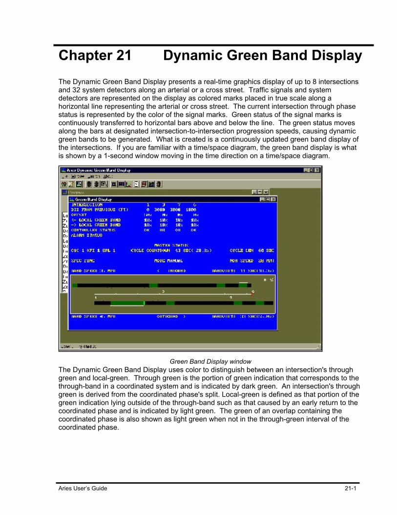
Aries User’s Guide 21-1
Chapter 21 Dynamic Green Band Display The Dynamic Green Band Display presents a real-time graphics display of up to 8 intersections and 32 system detectors along an arterial or a cross street. Traffic signals and system detectors are represented on the display as colored marks placed in true scale along a horizontal line representing the arterial or cross street. The current intersection through phase status is represented by the color of the signal marks. Green status of the signal marks is continuously transferred to horizontal bars above and below the line. The green status moves along the bars at designated intersection-to-intersection progression speeds, causing dynamic green bands to be generated. What is created is a continuously updated green band display of the intersections. If you are familiar with a time/space diagram, the green band display is what is shown by a 1-second window moving in the time direction on a time/space diagram.
Green Band Display window
The Dynamic Green Band Display uses color to distinguish between an intersection's through green and local-green. Through green is the portion of green indication that corresponds to the through-band in a coordinated system and is indicated by dark green. An intersection's through green is derived from the coordinated phase's split. Local-green is defined as that portion of the green indication lying outside of the through-band such as that caused by an early return to the coordinated phase and is indicated by light green. The green of an overlap containing the coordinated phase is also shown as light green when not in the through-green interval of the coordinated phase.

Dynamic Green Band Display
21-2 Aries User’s Guide
When a through-green band reaches an adjacent intersection, a check is made as to whether that adjacent intersection is also in the through-green interval. A star is placed next to the signal mark to indicate where the through-green band is being shortened or blocked. The display shows the intersections' intersection-to-intersection distances, their offsets, individual through-green values and status. Current system operating parameters, cycle countdown, cycle length, special function information, master mode of operation and the master's nominal speed are also displayed. The arterial or cross street through-green bandwidth for both directions is continuously calculated by monitoring how the through-green band generated at the end intersection, moves past the other intersections and is influenced by their signal indications. A white line above or below the bar showing the bands, indicates which band is being monitored. Its position and length indicate how the original end intersection's through-green was affected. The current through-green bandwidth is expressed in seconds and percent of cycle length and is shown next to the graphics window. The speed of the leading edge of the currently monitored band is also shown.
Operation To run the display:
1. Select Perform Display from the file menu of the Dynamic Green Band Display application.
2. If you have not yet selected a zone, a zone selection dialog box appears. Select a zone and click OK.
3. Next, the intersection selection dialog box appears. Select the arterial or cross street group desired. The intersections within the group are then shown.
4. Click on the starting and ending intersections in the Start Intersection and End Intersection list boxes. A green band display window appears and data acquisition begins.
The zone master database does not contain plan cycle length or plan nominal speed data. If the master is set up to use a cycle 7 plan, the display is suspended until the cycle length and nominal speed used by that plan is input. The program prompts the user for the entries. Nominal speed is from cycle 1, offset 1 when the system is free. The display is temporarily suspended when nominal speed is inappropriate for the distance scale. The display scale is optimized for typical arterial distances and speeds. If a particular display has short intersection-to-intersection distances and the operating nominal speed is high, the scale is cut in half and the display is redrawn. It is automatically restarted after being re-scaled.
Dynamic Green Band Display
Aries User’s Guide 21-3
Generating the Dynamic Green Band Database The Dynamic Green Band Database is organized into seven property
sheets; four sheets of intersection group data, a sheet dedicated to detector data, a sheet relating to plan data and a sheet relating to multiple speed selection and speed values. The intersection data sheets organize intersections into four groups where group 1 is designated as the arterial group and groups 2, 3 and 4 are cross street groups. The purpose of four groups is to allow accurate representations of cross street synchronization and/or where the coordinated phase(s) changes dynamically. In cross street synchronization, an intersection that is part of the main arterial can also relate to intersections in the cross street group of intersections. If this intersection's controller is an ASC-8000, for example, the alternate coordinated phase(s) is programmed so that under certain conditions a through-green band along the cross street is guaranteed. Specifying this intersection number and its related parameters in both the arterial and a cross street group produces an accurate representation of either group's operating conditions.
There are situations where, even though the same intersections are involved, alternate coordinated phases are used to set up distinct flow patterns or guaranteed through-green bands. Setting up two groups with the same intersection numbers and intersection-to-intersection distances, but different directional phases, sets up the relevant displays. An arterial with a freeway on/off ramp in the middle is a good illustration of this. During the day, the coordinated phases and timings are set up so that there is a balanced flow of traffic in both directions along the arterial. During the evening rush hour, however, the coordinated phases and timings are set up so that traffic flow originates at the off ramp and is optimized to proceed outward in both arterial directions. Master and intersection databases used in the display must be fully programmed as to cycle length, coordinated phases, speed, offsets and splits. Be sure intersections are setup to have all (or appropriate) offsets associated with both Direction 1 and Direction 2 Offset Assignment entries. To edit the Dynamic Green Band database, choose Edit Database from the File menu of the Dynamic Green Band Display application. If you have not yet selected a zone, a zone selection dialog starts. Select a zone and click OK. The Green Band Database dialog box pop up, as in the following figure.
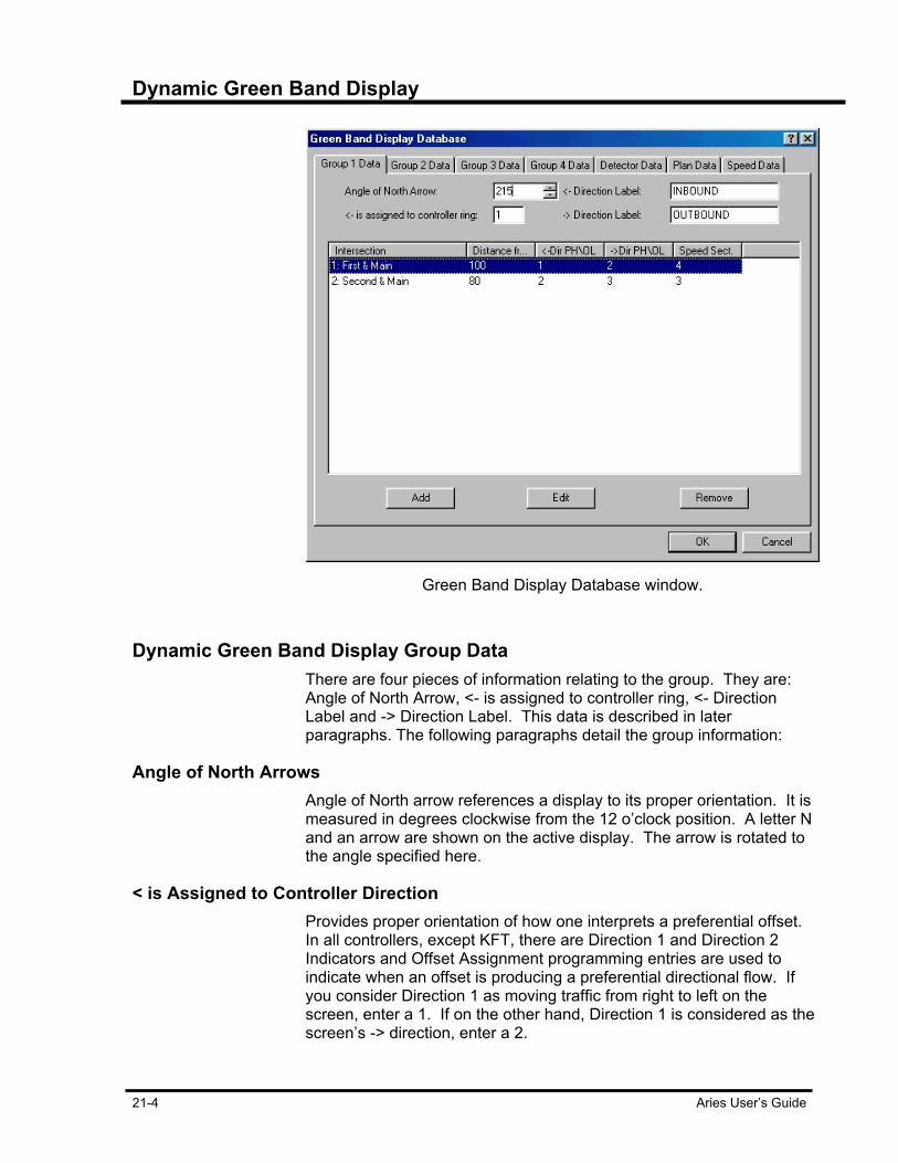
Dynamic Green Band Display
21-4 Aries User’s Guide
Green Band Display Database window.
Dynamic Green Band Display Group Data There are four pieces of information relating to the group. They are:
Angle of North Arrow, <- is assigned to controller ring, <- Direction Label and -> Direction Label. This data is described in later paragraphs. The following paragraphs detail the group information:
Angle of North Arrows Angle of North arrow references a display to its proper orientation. It is
measured in degrees clockwise from the 12 o’clock position. A letter N and an arrow are shown on the active display. The arrow is rotated to the angle specified here.
< is Assigned to Controller Direction Provides proper orientation of how one interprets a preferential offset.
In all controllers, except KFT, there are Direction 1 and Direction 2 Indicators and Offset Assignment programming entries are used to indicate when an offset is producing a preferential directional flow. If you consider Direction 1 as moving traffic from right to left on the screen, enter a 1. If on the other hand, Direction 1 is considered as the screen’s -> direction, enter a 2.
Dynamic Green Band Display
Aries User’s Guide 21-5
<- and -> Direction Labels Initially set to designate traffic moving in the <- direction as INBOUND
and -> direction as OUTBOUND. They may be changed to any eight-character label.
Dynamic Green Band Display Intersection Data This is a list containing up to eight intersections for the current group.
Intersections are added by pressing the Add button. A dialog box pops up. Select an intersection from the list in the dialog box. Fill in the other data (described in later paragraphs) and click OK. The intersection is added to the end of the list. To change the order of intersections in the list, click on the intersection and drag it on top of another intersection, then release the mouse button. The dragged intersection is inserted before the other intersection. The following paragraphs detail the intersection information.
Intersection An intersection controller in the zone. Intersections do not have to be
entered in order of their intersection numbers. The display shows them in the order they are entered and from left to right on the display.
Distance from Previous Distance from the previous intersection and must always be positive.
Even though the entry allows up to 9999 units from the previous intersection, be aware that the maximum overall distance of the intersections selected for display cannot be greater than 32,767 feet (9,986 meters).
<- and -> Direction Phase or Overlap Phase or overlap moving traffic along the arterial or cross street in the
given direction. This is one of the coordinated phases or an overlap containing one of the coordinated phases. Keep in mind that an ASC/2 or ASC-8000 controller's alternate coordinated phases may be assigned to different groups to provide accurate representations of alternate traffic patterns or cross street coordination.
Speed Section Specifies whether the zone master's nominal speed or a special section
speed from the speed table is to be used to move the band created by the intersection. Enter a 0 to select the zone master's nominal speed. Entering a 1, 2, 3 or 4 selects the section speed from the table. When a section speed is selected, the cycle and offset parameters in effect dynamically select which speed table entry or line is used. A school speed zone, active only during parts of the day, is an example of how this feature is applied.
Dynamic Green Band Display
21-6 Aries User’s Guide
Intersection Information Intersection information indicates parts of the intersection pertaining to
the Dynamic Green Band Display.
Lane Number Positions a system detector relative to the line representing the arterial
or cross street. A detector is positioned in any one of eight positions with Lane No. 1 being the inside lane in the -> direction and Lane No. 5 being the inside lane in the <- direction. Entering 0 eliminates the system detector display.
Intersection Reference Specifies the intersection a system detector location is referred to.
Distance from Intersection Distance of the system detector from a reference intersection. A
negative value positions the detector to the left of the intersection. If there is room, the program attempts to add space at the beginning and end of an arterial equal to the smallest distance between any two intersections to be displayed. Any of the displayed intersections' detectors falling within this space are shown.
Dynamic Green Band Display Plan Data This sheet provides entry space for selecting one of sixteen speed table
lines to be under various operating conditions. Cycle and offset or plan-in-effect selects a speed table line. The intersection's section speed entry determines the specific speed on that line.
Loading Master and Intersection Data into Green Band Database After arterial and cross street group configurations are set, appropriate
data from master and intersection databases should be loaded into the green band database and checked. The green band database is not automatically updated when changes are made in master or intersection databases. To update, select Edit Database from the File menu and click OK. The program begins transferring data from master and local controller files to the green band database. At the same time, data validation is performed. An error message is displayed if a database cannot be found or a KFT controller's through phase(s) is not programmed properly. A warning message is displayed if an intersection's cycle length data is not the same as the master's. After reviewing the validation messages, click OK to close the Validation Messages Box. The Dynamic Green Band Display application is ready to perform a display.
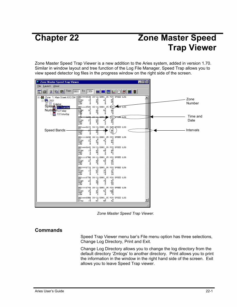
Aries User’s Guide 22-1
Chapter 22 Zone Master Speed Trap Viewer Zone Master Speed Trap Viewer is a new addition to the Aries system, added in version 1.70. Similar in window layout and tree function of the Log File Manager, Speed Trap allows you to view speed detector log files in the progress window on the right side of the screen.
Zone Master Speed Trap Viewer.
Commands Speed Trap Viewer menu bar’s File menu option has three selections,
Change Log Directory, Print and Exit. Change Log Directory allows you to change the log directory from the default directory ‘Zmlogs’ to another directory. Print allows you to print the information in the window in the right hand side of the screen. Exit allows you to leave Speed Trap viewer.
Zone Number
Speed Trap Number
Time and Date
Speed Bands Intervals

Zone Master Speed Trap Viewer
22-2 Aries User’s Guide
Speed Trap Display Speed Trap displays the five line information logs in 15-, 30- or 60-
minute increments called intervals. The first line begins with the zone number, followed by the time and date of the entry and the time interval of the log itself. The second line shows the speed trap numbers for that zone. Each zone shows up to eight speed traps. The third, forth and fifth lines show the speed band amounts, or the number of cars traveling between certain speeds during that interval. The thresholds for the three bands are defined in the master controller under Logging Parameters.
Intervals Interval refers to the time increment of each log. Intervals can be set to
15, 30 or 60-minute increments. Interval times are set in the Master Data Entry screens. In the Master Data Entry screen, select Logging Parameters from the Item List. In the General Tab, ‘Default SD and SPD Log Period’ pertains to setting the interval during which speed trap logs are taken. For example, when you select 30 from the ‘Default SD and SPD Log Period’ drop down box, the speed trap logs display the zone, time and date, interval amount, trap number and show the amount of cars counted in high, nominal and low ranges.
Acquiring and Displaying Information When Aries Zone Manager uploads data entry information from a zone
or intersection controller or an intersection monitor, those files are copied to the hard drive and used as master files. Those master files contain log files that are stored in the ‘Zmlogs’ directory.
Zmlogs directory

Zone Master Speed Trap Viewer
Aries User’s Guide 22-3
‘Zmlogs’ directory lists detector logs and event files with a slightly unusual naming convention. Files beginning with ‘Ev’ are event files. Files beginning with ‘Lg’ are detector logs. The numbers following these designations indicate the dates of the files in the MMDDYY format. The number after the period indicates the zone the information pertains to. For example, an event log from zone 7 dated, October 23, 2001 appears as ‘Ev102301.3’ in the ‘Zmlogs’ directory. ‘Lg101799.3’ indicates a detector log file from October 17, 1999 pertaining to zone 3. These files display all speed events for a 24-hour period.
Time Indicators In Speed Trap Viewer’s icon menu, there are two field boxes labeled
‘From’ and ‘To.’ These field boxes provide a means of filtering the log information to show all the records that were recorded between certain times.
Time Indicators
To view logs for specific times, enter in a ‘From’ or beginning time (times must be entered in military format) and a ‘To’ or ending time. In the example shown below, logs are shown for the times between 5:00 p.m. and 7:00 p.m. 5:00 p.m. is listed as 1700 military time and 7:00 p.m. is entered as 1900. The logs shown in the Progress window were taken between 5:00 p.m. and 7:00 p.m.
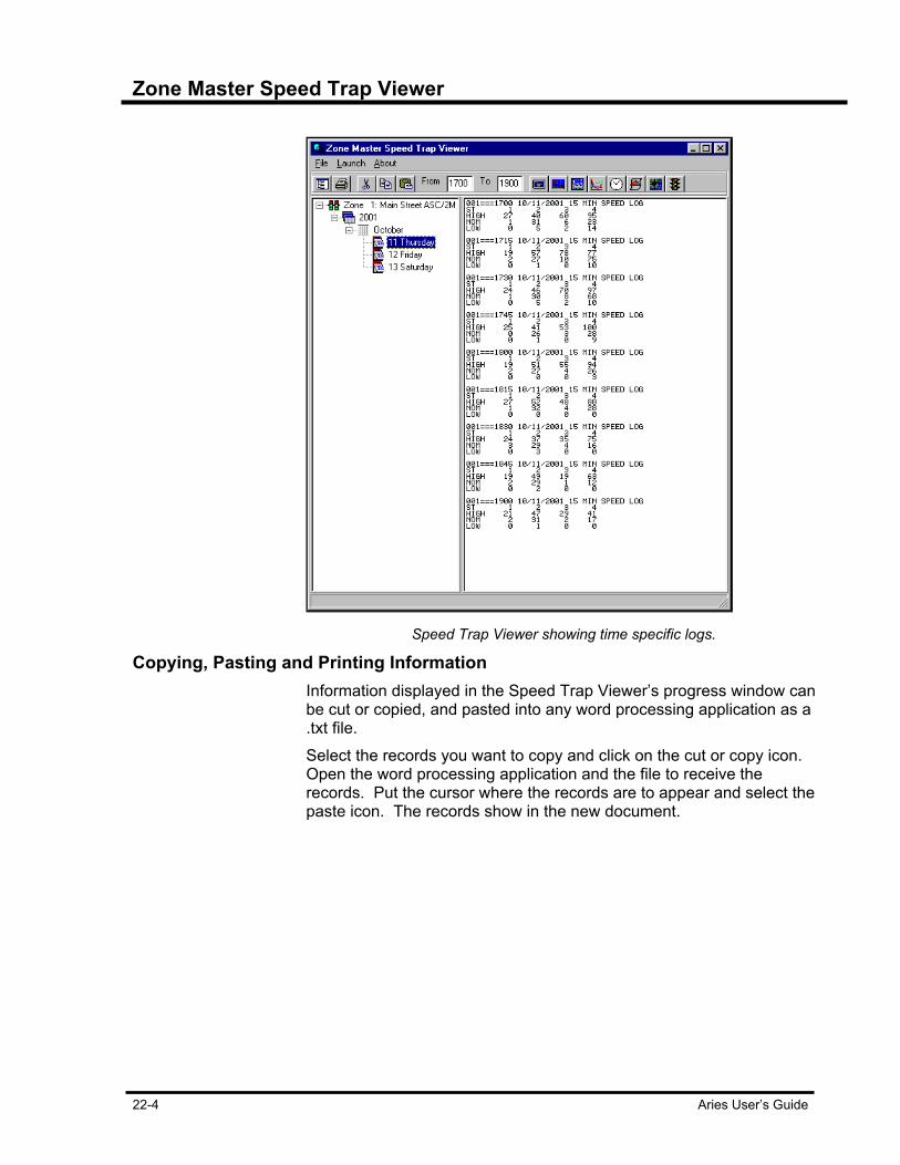
Zone Master Speed Trap Viewer
22-4 Aries User’s Guide
Speed Trap Viewer showing time specific logs.
Copying, Pasting and Printing Information Information displayed in the Speed Trap Viewer’s progress window can
be cut or copied, and pasted into any word processing application as a .txt file. Select the records you want to copy and click on the cut or copy icon. Open the word processing application and the file to receive the records. Put the cursor where the records are to appear and select the paste icon. The records show in the new document.
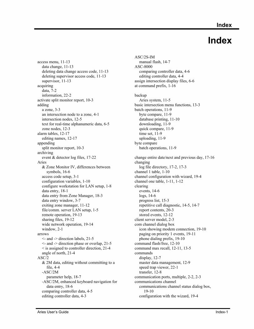
Index
Aries User’s Guide Index-1
Index access menu, 11-13
data change, 11-13 deleting data change access code, 11-13 deleting supervisor access code, 11-13 supervisor, 11-13
acquiring data, 7-2 information, 22-2
activate split monitor report, 10-3 adding
a zone, 3-3 an intersection node to a zone, 4-1 intersection nodes, 12-5 text for real-time alphanumeric data, 6-5 zone nodes, 12-3
alarm tables, 12-17 editing names, 12-17
appending split monitor report, 10-3
archiving event & detector log files, 17-22
Aries & Zone Monitor IV, differences between
symbols, 16-6 access code setup, 3-1 configuration variables, 1-10 configure workstation for LAN setup, 1-8 data entry, 18-1 data entry from Zone Manager, 18-3 data entry window, 3-7 exiting zone manager, 11-12 file/comm. server LAN setup, 1-5 remote operation, 19-13 sharing files, 19-12 wide network operation, 19-14 window, 2-1
arrows <- and -> direction labels, 21-5 <- and -> direction phase or overlap, 21-5 < is assigned to controller direction, 21-4 angle of north, 21-4
ASC/2 & 2M data, editing without committing to a
file, 4-4 -ASC/2M
parameter help, 18-7 -ASC/2M, enhanced keyboard navigation for
data entry, 18-6 comparing controller data, 4-5 editing controller data, 4-3
ASC/2S-IM manual flash, 14-7
ASC-8000 comparing controller data, 4-6 editing controller data, 4-4
assign intersection display files, 6-6 at command prefix, 1-16 backup
Aries system, 11-5 basic intersection menu functions, 13-3 batch operations, 11-9
byte compare, 11-9 database printing, 11-10 downloading, 11-9 quick compare, 11-9 time set, 11-9 uploading, 11-9
byte compare batch operations, 11-9
change entire date/next and previous day, 17-16 changing
log file directory, 17-2, 17-3 channel 1 table, 1-10 channel configuration with wizard, 19-4 channel one table, 1-11, 1-12 clearing
events, 14-6 logs, 14-6 progress list, 15-3 repetitive call diagnostic, 14-5, 14-7 report contents, 20-3 stored events, 12-12
client server model, 2-3 com channel dialog box
icon showing modem connection, 19-10 paging on priority 1 events, 19-11 phone dialing prefix, 19-10
command flash/free, 12-10 command max recall, 12-11, 13-5 commands
display, 12-7 master data management, 12-9 speed trap viewer, 22-1 transfer, 12-8
communication ports, multiple, 2-2, 2-3 communications channel
communications channel status dialog box, 19-10
configuration with the wizard, 19-4
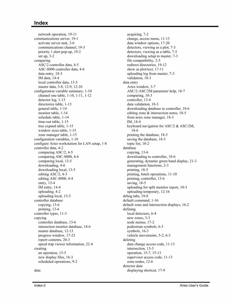
Index
Index-2 Aries User’s Guide
network operation, 19-11 communications server, 19-1
activate server task, 3-6 communications channel, 19-3 priority 1 alert pop-up, 19-2 set up, 3-2
comparing ASC/2 controller data, 4-5 ASC-8000 controller data, 4-6 data entry, 18-3 IM data, 14-4 local controller data, 13-5 master data, 3-8, 12-9, 12-10
configuration variable summary, 1-10 channel one table, 1-10, 1-11, 1-12 detector log, 1-13 directories table, 1-13 general table, 1-14 monitor table, 1-14 schedule table, 1-14 time-out table, 1-15 tree expand table, 1-15 window sizes table, 1-15 zone manager table, 1-15
configuration variables, 1-10 configure Aries workstation for LAN setup, 1-8 controller data, 4-2
comparing ASC/2, 4-5 comparing ASC-8000, 4-6 comparing local, 13-5 downloading, 4-6 downloading local, 13-5 editing ASC/2, 4-3 editing ASC-8000, 4-4 entry, 13-4 IM entry, 14-4 uploading, 4-2 uploading local, 13-5
controller database copying, 13-6 printing, 13-6
controller types, 11-3 copying
controller database, 13-6 intesection monitor database, 14-6 master database, 12-13 progress window, 17-23 report contents, 20-3 speed trap viewer information, 22-4
creating an operation, 15-5 new display files, 16-3 scheduled operations, 9-2
data
acquiring, 7-2 change, access menu, 11-13 data window options, 17-20 detectors, viewing as a plot, 7-3 detectors, viewing as a table, 7-5 downloading setup to master, 7-3 file compatibility, 2-5 redirect directories, 19-12 show as plot/text, 17-11 uploading log from master, 7-3 validation, 18-3
data entry Aries window, 3-7 ASC/2-ASC/2M parameter help, 18-7 comparing, 18-3 controller, 13-4 data validation, 18-3 downloading database to controller, 18-6 editing zone & intersection notes, 18-5 from aries zone manager, 18-3 IM, 14-4 keyboard navigation for ASC/2 & ASC/2M,
18-6 printing the database, 18-5 saving the database, 18-5 topic list, 18-2
database copying, 13-6 downloading to controller, 18-6 generating, dynamic green band display, 21-3 management functions, 2-3 printing, 18-5 printing, batch operations, 11-10 printing, controller, 13-6 saving, 18-5 uploading for split monitor report, 10-3 uploading temporary, 12-16
debug tabs, 19-8 default command, 1-16 default zone and intersection displays, 16-2 defining
local detectors, 6-4 new zones, 3-3 node menus, 17-2 pedestrian symbols, 6-3 symbols, 16-3 vehicle movements, 5-2, 6-3
deleting data change access code, 11-13 intersection, 13-3 operation, 15-7, 15-13 supervisor access code, 11-13 zone nodes, 12-6
detector data displaying shortcut, 17-9
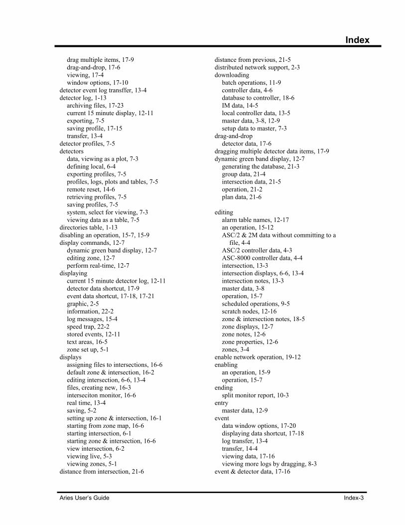
Index
Aries User’s Guide Index-3
drag multiple items, 17-9 drag-and-drop, 17-6 viewing, 17-4 window options, 17-10
detector event log transffer, 13-4 detector log, 1-13
archiving files, 17-23 current 15 minute display, 12-11 exporting, 7-5 saving profile, 17-15 transfer, 13-4
detector profiles, 7-5 detectors
data, viewing as a plot, 7-3 defining local, 6-4 exporting profiles, 7-5 profiles, logs, plots and tables, 7-5 remote reset, 14-6 retrieving profiles, 7-5 saving profiles, 7-5 system, select for viewing, 7-3 viewing data as a table, 7-5
directories table, 1-13 disabling an operation, 15-7, 15-9 display commands, 12-7
dynamic green band display, 12-7 editing zone, 12-7 perform real-time, 12-7
displaying current 15 minute detector log, 12-11 detector data shortcut, 17-9 event data shortcut, 17-18, 17-21 graphic, 2-5 information, 22-2 log messages, 15-4 speed trap, 22-2 stored events, 12-11 text areas, 16-5 zone set up, 5-1
displays assigning files to intersections, 16-6 default zone & intersection, 16-2 editing intersection, 6-6, 13-4 files, creating new, 16-3 interseciton monitor, 16-6 real time, 13-4 saving, 5-2 setting up zone & intersection, 16-1 starting from zone map, 16-6 starting intersection, 6-1 starting zone & intersection, 16-6 view intersection, 6-2 viewing live, 5-3 viewing zones, 5-1
distance from intersection, 21-6
distance from previous, 21-5 distributed network support, 2-3 downloading
batch operations, 11-9 controller data, 4-6 database to controller, 18-6 IM data, 14-5 local controller data, 13-5 master data, 3-8, 12-9 setup data to master, 7-3
drag-and-drop detector data, 17-6
dragging multiple detector data items, 17-9 dynamic green band display, 12-7
generating the database, 21-3 group data, 21-4 intersection data, 21-5 operation, 21-2 plan data, 21-6
editing
alarm table names, 12-17 an operation, 15-12 ASC/2 & 2M data without committing to a
file, 4-4 ASC/2 controller data, 4-3 ASC-8000 controller data, 4-4 intersection, 13-3 intersection displays, 6-6, 13-4 intersection notes, 13-3 master data, 3-8 operation, 15-7 scheduled operations, 9-5 scratch nodes, 12-16 zone & intersection notes, 18-5 zone displays, 12-7 zone notes, 12-6 zone properties, 12-6 zones, 3-4
enable network operation, 19-12 enabling
an operation, 15-9 operation, 15-7
ending split monitor report, 10-3
entry master data, 12-9
event data window options, 17-20 displaying data shortcut, 17-18 log transfer, 13-4 transfer, 14-4 viewing data, 17-16 viewing more logs by dragging, 8-3
event & detector data, 17-16
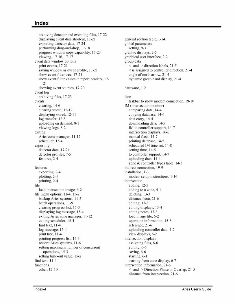
Index
Index-4 Aries User’s Guide
archiving detector and event log files, 17-22 displaying event data shortcut, 17-21 exporting detector data, 17-24 performing drag-and-drop, 17-18 progress window copy capability, 17-23 viewing, 17-16, 17-17
event data window options print events, 17-21 saving window as event profile, 17-21 show event filter tree, 17-21 show event filter values in report headers, 17-
21 showing event sources, 17-20
event log archiving files, 17-23
events clearing, 14-6 clearing stored, 12-12 displaying stored, 12-11 log transfer, 12-8 uploading on demand, 8-1 viewing logs, 8-2
exiting Aries zone manager, 11-12 scheduler, 15-4
exporting detector data, 17-24 detector profiles, 7-5 features, 2-4
features
exporting, 2-4 plotting, 2-4 printing, 2-4
file load intersection image, 6-2
file menu options, 11-4, 15-2 backup Aries systems, 11-5 batch operations, 11-9 clearing progress list, 15-3 displaying log message, 15-4 exiting Aries zone manager, 11-12 exiting scheduler, 15-4 find text, 11-4 log message, 15-4 print tree, 11-4 printing progress list, 15-3 restore Aries systems, 11-6 setting maximum number of concurrent
operations, 15-3 setting time-out value, 15-2
find text, 11-4 functions
other, 12-10
general section table, 1-14 global parameters
setting, 9-3 graphic displays, 2-5 graphical user interface, 2-2 group data
<- and -> direction labels, 21-5 < is assigned to controller direction, 21-4 angle of north arrow, 21-4 dynamic green band display, 21-4
hardware, 1-2 icon
taskbar to show modem connection, 19-10 IM (intersection monitor)
comparing data, 14-4 copying database, 14-6 data entry, 14-4 downloading data, 14-5 IM to controller support, 14-7 intersection displays, 16-6 manual flash, 14-7 printing database, 14-5 scheduled IM time set, 14-8 setting time, 14-5 to controller support, 14-7 uploading data, 14-4 zone & controller types table, 14-3
indirect connection, 19-9 installation, 1-3
modem setup instructions, 1-16 intersection
adding, 12-5 adding to a zone, 4-1 deleting, 13-3 distance from, 21-6 editing, 13-3 editing displays, 13-4 editing notes, 13-3 load image file, 6-2 operation information, 15-8 reference, 21-6 uploading controller data, 4-2 view displays, 6-2
intersection displays assigning files, 6-6 editing, 6-6 saving, 6-6 starting, 6-1 starting from zone display, 6-7
intersection information, 21-6 <- and -> Direction Phase or Overlap, 21-5 distance from intersection, 21-6
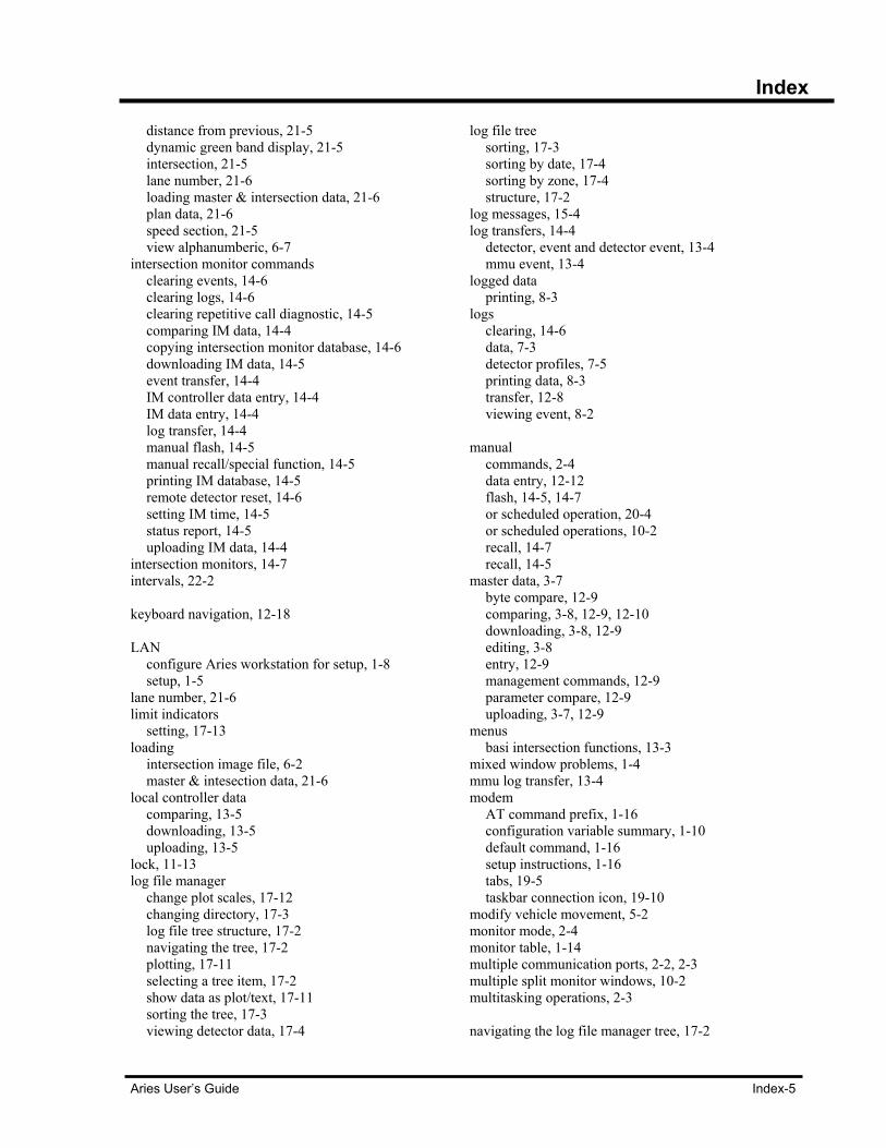
Index
Aries User’s Guide Index-5
distance from previous, 21-5 dynamic green band display, 21-5 intersection, 21-5 lane number, 21-6 loading master & intersection data, 21-6 plan data, 21-6 speed section, 21-5 view alphanumberic, 6-7
intersection monitor commands clearing events, 14-6 clearing logs, 14-6 clearing repetitive call diagnostic, 14-5 comparing IM data, 14-4 copying intersection monitor database, 14-6 downloading IM data, 14-5 event transfer, 14-4 IM controller data entry, 14-4 IM data entry, 14-4 log transfer, 14-4 manual flash, 14-5 manual recall/special function, 14-5 printing IM database, 14-5 remote detector reset, 14-6 setting IM time, 14-5 status report, 14-5 uploading IM data, 14-4
intersection monitors, 14-7 intervals, 22-2 keyboard navigation, 12-18 LAN
configure Aries workstation for setup, 1-8 setup, 1-5
lane number, 21-6 limit indicators
setting, 17-13 loading
intersection image file, 6-2 master & intesection data, 21-6
local controller data comparing, 13-5 downloading, 13-5 uploading, 13-5
lock, 11-13 log file manager
change plot scales, 17-12 changing directory, 17-3 log file tree structure, 17-2 navigating the tree, 17-2 plotting, 17-11 selecting a tree item, 17-2 show data as plot/text, 17-11 sorting the tree, 17-3 viewing detector data, 17-4
log file tree sorting, 17-3 sorting by date, 17-4 sorting by zone, 17-4 structure, 17-2
log messages, 15-4 log transfers, 14-4
detector, event and detector event, 13-4 mmu event, 13-4
logged data printing, 8-3
logs clearing, 14-6 data, 7-3 detector profiles, 7-5 printing data, 8-3 transfer, 12-8 viewing event, 8-2
manual
commands, 2-4 data entry, 12-12 flash, 14-5, 14-7 or scheduled operation, 20-4 or scheduled operations, 10-2 recall, 14-7 recall, 14-5
master data, 3-7 byte compare, 12-9 comparing, 3-8, 12-9, 12-10 downloading, 3-8, 12-9 editing, 3-8 entry, 12-9 management commands, 12-9 parameter compare, 12-9 uploading, 3-7, 12-9
menus basi intersection functions, 13-3
mixed window problems, 1-4 mmu log transfer, 13-4 modem
AT command prefix, 1-16 configuration variable summary, 1-10 default command, 1-16 setup instructions, 1-16 tabs, 19-5 taskbar connection icon, 19-10
modify vehicle movement, 5-2 monitor mode, 2-4 monitor table, 1-14 multiple communication ports, 2-2, 2-3 multiple split monitor windows, 10-2 multitasking operations, 2-3 navigating the log file manager tree, 17-2

Index
Index-6 Aries User’s Guide
network operation enable, 19-12 redirect data directories, 19-12 remote Aries operation, 19-13 sharing Aries files, 19-12 sharing communications server services, 19-
12 wide Aries, 19-14
node(s) add zone dialog box, 12-3 adding intersection, 12-5 adding intersection to a zone, 4-1 defined menus, 17-2 deleting, 12-6 editing properties, 12-6 editing scratch, 12-16 root menu, 12-3 temporary scratch, 12-14 zone menus, 12-4
occupancy grid, 17-13 open
split monitor report window, 10-2 open a split monitor report window, 10-2 operation
manual or scheduled, 20-4 operations
batch, 11-9 byte compare, 11-9 creating, 15-5 creating scheduled, 9-2 deleting, 15-13 downloading batch, 11-9 dynamic green band display, 21-2 editing, 15-12 editing scheduled, 9-5 editing, enabling, disabling or deleting
information, 15-7 enable network, 19-12 enabling/disabling, 15-9 information, 15-7 intersection information, 15-8 manual or scheduled, 10-2, 20-4 multitasking, 2-3 network, 19-11 performing, 15-10 printing database, 11-10 quick compare, 11-9 remote Aries, 19-13 repeat, 9-4 resume scanning for, 15-7 right-click popup menu items, 15-7 schedule menu options, 15-5 scheduled that repeat, 15-11 scheduler, 2-4
scheduling, 15-8 setting maximum number of concurrent, 15-3 suspend scanning for, 15-6, 15-7 time set batch, 11-9 uploading batch, 11-9 viewing, 15-13 viewing scheduled, 9-5 wide Aries network, 19-14 with repeat counts, 15-11 with Zone Manager IV, 2-5
options tabs, 19-7 other functions, 12-10
clearing stored events, 12-12 command flash/free, 12-10 command max recall, 12-11 comparing master data, 12-10 copying master database, 12-13 displaying current 15 minute detector log, 12-
11 displaying stored events, 12-11 manual data entry, 12-12 printing master database, 12-12 setting master time, 12-10
pager tab, 19-9 paging on priority 1 events, 19-11 parameter help
ASC/2-ASC/2M, 18-7 pasting
speed trap viewer information, 22-4 pedestrian
defining symbols, 6-3 symbols, 16-4
performing drag & drop for event data, 17-18 operations, 15-10 real-time displays, 12-7
plan data dynamic green band display, 21-6
plots printing, 7-6, 17-16
plots and tables, 7-5 plotting, 17-11
change entire date/next and previous day, 17-16
change scales, 17-12 data plot zoom capability, 17-15 features, 2-4 grids, volume/occupancy/speed, 17-13
port tab, 19-4 print tree, 11-4 printing
all or selection of split monitor report, 10-3 controller database, 13-6 database, 18-5
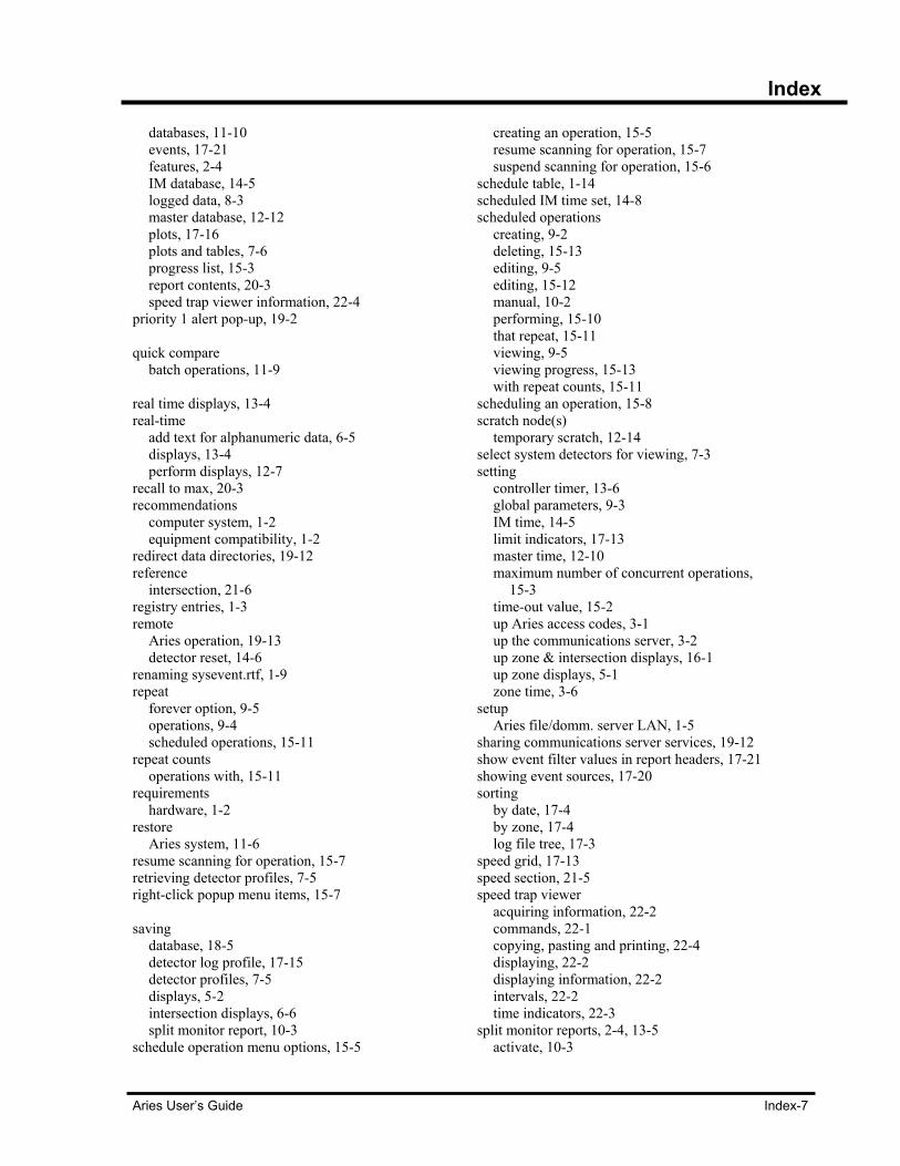
Index
Aries User’s Guide Index-7
databases, 11-10 events, 17-21 features, 2-4 IM database, 14-5 logged data, 8-3 master database, 12-12 plots, 17-16 plots and tables, 7-6 progress list, 15-3 report contents, 20-3 speed trap viewer information, 22-4
priority 1 alert pop-up, 19-2 quick compare
batch operations, 11-9 real time displays, 13-4 real-time
add text for alphanumeric data, 6-5 displays, 13-4 perform displays, 12-7
recall to max, 20-3 recommendations
computer system, 1-2 equipment compatibility, 1-2
redirect data directories, 19-12 reference
intersection, 21-6 registry entries, 1-3 remote
Aries operation, 19-13 detector reset, 14-6
renaming sysevent.rtf, 1-9 repeat
forever option, 9-5 operations, 9-4 scheduled operations, 15-11
repeat counts operations with, 15-11
requirements hardware, 1-2
restore Aries system, 11-6
resume scanning for operation, 15-7 retrieving detector profiles, 7-5 right-click popup menu items, 15-7 saving
database, 18-5 detector log profile, 17-15 detector profiles, 7-5 displays, 5-2 intersection displays, 6-6 split monitor report, 10-3
schedule operation menu options, 15-5
creating an operation, 15-5 resume scanning for operation, 15-7 suspend scanning for operation, 15-6
schedule table, 1-14 scheduled IM time set, 14-8 scheduled operations
creating, 9-2 deleting, 15-13 editing, 9-5 editing, 15-12 manual, 10-2 performing, 15-10 that repeat, 15-11 viewing, 9-5 viewing progress, 15-13 with repeat counts, 15-11
scheduling an operation, 15-8 scratch node(s)
temporary scratch, 12-14 select system detectors for viewing, 7-3 setting
controller timer, 13-6 global parameters, 9-3 IM time, 14-5 limit indicators, 17-13 master time, 12-10 maximum number of concurrent operations,
15-3 time-out value, 15-2 up Aries access codes, 3-1 up the communications server, 3-2 up zone & intersection displays, 16-1 up zone displays, 5-1 zone time, 3-6
setup Aries file/domm. server LAN, 1-5
sharing communications server services, 19-12 show event filter values in report headers, 17-21 showing event sources, 17-20 sorting
by date, 17-4 by zone, 17-4 log file tree, 17-3
speed grid, 17-13 speed section, 21-5 speed trap viewer
acquiring information, 22-2 commands, 22-1 copying, pasting and printing, 22-4 displaying, 22-2 displaying information, 22-2 intervals, 22-2 time indicators, 22-3
split monitor reports, 2-4, 13-5 activate, 10-3
Index
Index-8 Aries User’s Guide
ending, saving and appending, 10-3 multiple windows, 10-2 opening a window, 10-2 printing all or a selection of, 10-3 starting a report, 20-2 uploading database, 10-3
split monitor window, 20-2 clearing, copying & printing a report, 20-3 manual or scheduled operation, 20-4 recall to max, 20-3 stopping a report, 20-3
starting a split monitor report, 20-2 intersection display from zone map, 16-6 intersection displays, 6-1 intersection displays from zone display, 6-7 zone & intersection displays, 16-6
status dialog box communications channel, 19-10
status report, 14-5 stopping
a report, 20-3 stored events
clearing, 12-12 displaying, 12-11
supervisor access menu, 11-13
suspend scanning for operation, 15-6 symbols
defining, 16-3 differences between Aries and Zone Monitor
IV, 16-6 examining, 16-5
sysevent.rtf renaming, 1-9
tables
& plots, 7-5 alarms, 12-17 configuration variable summary, 1-10, 1-11,
1-12 IM types, zones & controllers, 14-3 printing, 7-6 viewing detector data, 7-5
temporary scratch area, 12-14 temporary scratch nodes, 12-14 text areas
displaying, 16-5 time
indicators, 22-3 out period, 4-3 set controller, 13-6 set IM, 14-5 set scheduled IM, 14-8 set, batch operations, 11-9
setting master, 12-10 setting time-out values, 15-2 setting zone, 3-6
time-out table, 1-15 topic list, 18-2 transfer
event, 14-4 log, 14-4
transfer commands, 12-8 event
transfer, 12-8 log transfer, 12-8
tree expand table, 1-15 types
zones & controllers, 11-3 unlock, 11-13 uploading
batch operations, 11-9 controller data, 4-2 controller database for split monitor report,
10-3 events on demand, 8-1 IM data, 14-4 local controller data, 13-5 log data from master, 7-3 master data, 3-7, 12-9 temporary database, 12-16 time out period, 4-3
vehicle
defining movements, 5-2, 6-3 modify movement, 5-2
viewing alphanumberic intersection data, 6-7 detector data, 17-4 detector data as a plot, 7-3 detector data as a table, 7-5 detector data by date, 17-5 detector databy zone, 17-5 event & detector data, 17-16 event & detector data profiles, 17-17 event logs, 8-2 intersection displays, 6-2 live zone displays, 5-3 more event logs by dragging, 8-3 operation progress, 15-13 scheduled operations, 9-5 system detectors, 7-3 zone displays, 5-1
volume grid, 17-13 window sizes table, 1-15 wizard
channel configuration, 19-4
Index
Aries User’s Guide Index-9
debug tabs, 19-8 indirect connection, 19-9 modem tabs, 19-5 options tabs, 19-7 pager tab, 19-9 zone tabs, 19-6
zone & intersection
default displays, 16-2 editing notes, 18-5 setting up displays, 16-1
zone & intersection display creating new files, 16-3 defining symbols, 16-3 examining symbols, 16-5 starting, 16-6 text areas, 16-5
zone manager table, 1-15 Zone Monitor IV
data file compatibility, 2-5 operation with, 2-5
zone pop-up menu commands, 12-2
zone types, 11-3 zones, 3-3, 12-2
adding intersection nodes, 4-1 adding nodes, 12-3 channel configuration/wizard tabs, 19-6 defining, 3-3 defining vehicle movements, 5-2 deleting nodes, 12-6 display set up, 5-1 editing, 3-4 editing displays, 12-7 editing notes, 12-6 editing properties, 12-6 log file tree sorting by, 17-4 modify vehicle movement, 5-2 node menus, 12-4 one active task per, 5-3 saving displays, 5-2 time setting, 3-6 viewing detector data by, 17-5 viewing displays, 5-1 viewing live displays, 5-3