user’s guide on controlling locks, keys and access … · also included are specific hardware...
TRANSCRIPT
NAVAL FACILITIES ENGINEERING SERVICE CENTERPort Hueneme, California 93043-4370
USER’S GUIDEUG-2040-SHR
USER’S GUIDEON
CONTROLLING LOCKS, KEYSAND ACCESS CARDS
DoD Lock ProgramNaval Facilities Engineering Service Center
1100 23rd Ave.Port Hueneme, CA 93043
July 2000
Approved for public release; distribution is unlimited.
Printed on recycled paper
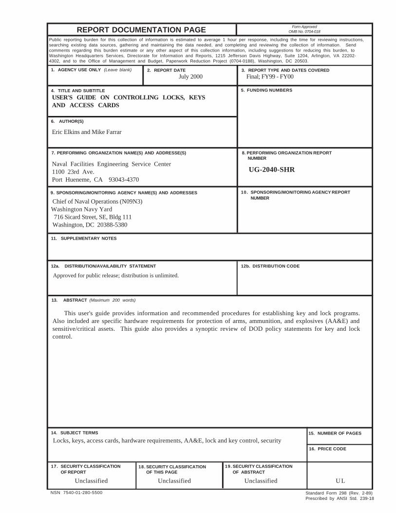
REPORT DOCUMENTATION PAGE Form ApprovedOMB No. 0704-018
Public reporting burden for this collection of information is estimated to average 1 hour per response, including the time for reviewing instructions,searching existing data sources, gathering and maintaining the data needed, and completing and reviewing the collection of information. Sendcomments regarding this burden estimate or any other aspect of this collection information, including suggestions for reducing this burden, toWashington Headquarters Services, Directorate for Information and Reports, 1215 Jefferson Davis Highway, Suite 1204, Arlington, VA 22202-4302, and to the Office of Management and Budget, Paperwork Reduction Project (0704-0188), Washington, DC 20503.
4. TITLE AND SUBTITLE
2. REPORT DATE1. AGENCY USE ONLY (Leave blank)
6. AUTHOR(S)
7. PERFORMING ORGANIZATION NAME(S) AND ADDRESSE(S)
3. REPORT TYPE AND DATES COVERED
5. FUNDING NUMBERS
8. PERFORMING ORGANIZATION REPORTNUMBER
10. SPONSORING/MONITORING AGENCY REPORTNUMBER
9. SPONSORING/MONITORING AGENCY NAME(S) AND ADDRESSES
11. SUPPLEMENTARY NOTES
12a. DISTRIBUTION/AVAILABILITY STATEMENT 12b. DISTRIBUTION CODE
18. SECURITY CLASSIFICATIONOF THIS PAGE
15. NUMBER OF PAGES
16. PRICE CODE
19. SECURITY CLASSIFICATIONOF ABSTRACT
NSN 7540-01-280-5500
17. SECURITY CLASSIFICATIONOF REPORT
Standard Form 298 (Rev. 2-89)Prescribed by ANSI Std. 239-18
14. SUBJECT TERMS
13. ABSTRACT (Maximum 200 words)
USER'S GUIDE ON CONTROLLING LOCKS, KEYSAND ACCESS CARDS
July 2000
Naval Facilities Engineering Service Center1100 23rd Ave.Port Hueneme, CA 93043-4370
Unclassified Unclassified Unclassified U L
UG-2040-SHR
Eric Elkins and Mike Farrar
Approved for public release; distribution is unlimited.
This user's guide provides information and recommended procedures for establishing key and lock programs.Also included are specific hardware requirements for protection of arms, ammunition, and explosives (AA&E) andsensitive/critical assets. This guide also provides a synoptic review of DOD policy statements for key and lockcontrol.
Final; FY99 - FY00
Chief of Naval Operations (N09N3) Washington Navy Yard
716 Sicard Street, SE, Bldg 111Washington, DC 20388-5380
Locks, keys, access cards, hardware requirements, AA&E, lock and key control, security
ii
EXECUTIVE SUMMARY
This user’s guide provides information and procedures that will aid in thedistribution and control of mechanical and electronic keys. An effective access control(lock and key or electronic) program will help minimize the possibility of unauthorizedaccess to a facility and/or assets in a facility. Possession of keys and access control cardsrepresent primary authorization for an individual to enter a facility or have access to aparticular asset. Possession of keys and access control cards by unauthorized individualsseverely affects security and neutralizes the primary purpose of an access controlprogram.
This user’s guide presents information on establishing a program for protectingDepartment of Defense (DoD) assets against covert or insider threats. This guide isdivided into five chapters and seven appendices that describe a process for controllinglocks, keys and access cards or credentials. Chapter 2 describes DoD requirements foraccess control. Chapter 3 provides a structured program for controlling locks, keys andaccess control cards. Chapter 4 provides descriptions of software and hardware that arecommercially available for controlling locks and keys. Chapter 5 provides a structuredprogram that specifically addresses the control of locks and keys that protect criticalassets. The appendices include a glossary of lock, key, and access control terms,references, a listing of manufacturers that offer software and hardware for access control,and forms that can be used to implement a comprehensive lock, key, or access cardcontrol program. The appendices also include a checklist for lock and key control, asample lock and key control plan, and a general description of electronic access controlsystems.
iii
CONTENTS Page
CHAPTER 1 INTRODUCTION ...................................................................................... 1-1
OBJECTIVE.......................................................................................................................... 1-1
SCOPE ................................................................................................................................. 1-1
BACKGROUND................................................................................................................... 1-1Levels of Protection .................................................................................................. 1-2Protection of Critical Assets ..................................................................................... 1-2
APPROACH ......................................................................................................................... 1-3
CHAPTER 2 DOD LOCK AND KEY CONTROL REQUIREMENTS .................... 2-1
INTRODUCTION ................................................................................................................ 2-1
REQUIREMENTS ............................................................................................................... 2-1
CHAPTER 3 ESTABLISHING A PROGRAM FOR CONTROLLING LOCKS, KEYS, OR ACCESS CREDENTIALS .................................. 3-1
INTRODUCTION ................................................................................................................ 3-1
MECHANICAL LOCKS AND KEYS ................................................................................ 3-1Personnel and Duties ................................................................................................ 3-1Key Control Training ............................................................................................... 3-3Facility Evaluation ................................................................................................... 3-4Procedures ................................................................................................................ 3-4Lock Maintenance .................................................................................................... 3-12Funding ..................................................................................................................... 3-12Documentation ......................................................................................................... 3-12
ELECTRONIC ACCESS CONTROL SYSTEMS .............................................................. 3-13Personnel and Duties ................................................................................................ 3-13Access Control Training ........................................................................................... 3-13Facility Evaluation ................................................................................................... 3-14Procedures ................................................................................................................ 3-14Maintenance ............................................................................................................. 3-15Funding ..................................................................................................................... 3-15Documentation ......................................................................................................... 3-15
iv
Page
CHAPTER 4 KEY CONTROL SOFTWARE AND EQUIPMENT ........................... 4-1
INTRODUCTION ................................................................................................................ 4-1
KEY CONTROL SOFTWARE AND HARDWARE ......................................................... 4-1
MECHANICAL LOCK AND KEY SYSTEMS ................................................................. 4-7Low-Security Locks and Cores ................................................................................ 4-7Interchangeable Core Systems ................................................................................. 4-13
KEY STORAGE EQUIPMENT .......................................................................................... 4-14General Key Storage ................................................................................................ 4-14Key Cabinets, Lockers, and Safes ............................................................................ 4-15Key Tags and Key Rings .......................................................................................... 4-18
CHAPTER 5 LOCK AND KEY CONTROL FOR CRITICAL ASSETS .................. 5-1
INTRODUCTION ................................................................................................................ 5-1
SPECIFIC REQUIREMENTS ............................................................................................. 5-1AA&E Facilities ....................................................................................................... 5-1C&SW Facilities ...................................................................................................... 5-2Sensitive and Highly Pilferable Material or Equipment .......................................... 5-2Designated Key Storage Containers ......................................................................... 5-2Lockouts ................................................................................................................... 5-4High-Security Lock Hardware ................................................................................. 5-5
APPENDIXES
A – Glossary of Lock, Key, and Access Control Terms .......................................... A-1B – References ......................................................................................................... B-1C – Sample Lock and Key Control Plans ................................................................. C-1D – Mechanical and Electronic Access Control ....................................................... D-1E – Lock and Key Control Forms ............................................................................ E-1F – Manufacturers Listing ........................................................................................ F-1G – Checklists for Lock and Key Control ................................................................ G-1
LIST OF FIGURES
Figure 3-1. Keyed-Alike System ....................................................................................... 3-6Figure 3-2. Master-Keyed System ..................................................................................... 3-7Figure 3-3. Sample Door Schedule .................................................................................... 3-8Figure 3-4. Emergency Key Box ....................................................................................... 3-11
v
Page
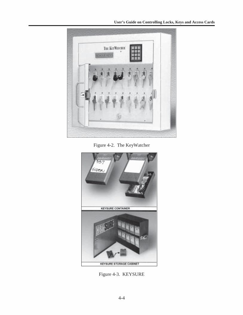
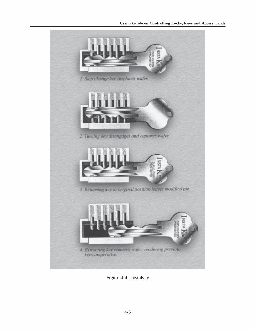
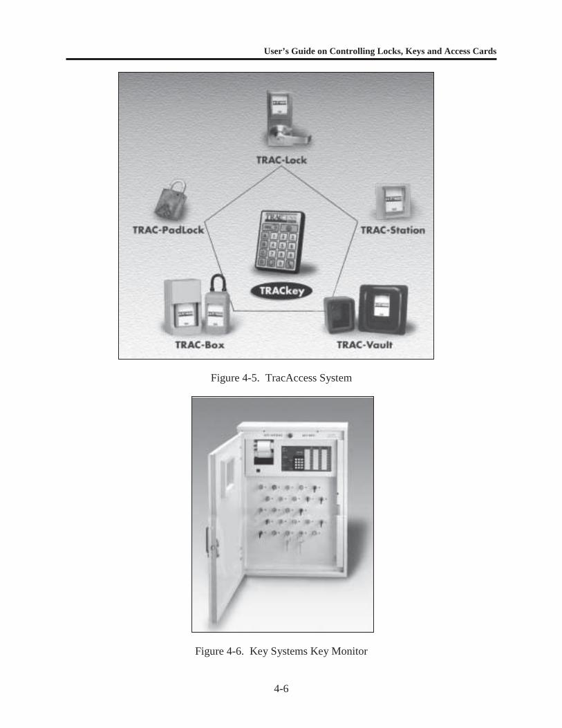
Figure 4-1. KeyTrak ........................................................................................................... 4-3Figure 4-2. The KeyWatcher ............................................................................................. 4-4Figure 4-3. KEYSURE ...................................................................................................... 4-4Figure 4-4. InstaKey .......................................................................................................... 4-5Figure 4-5. TracAccess System ......................................................................................... 4-6Figure 4-6. Key Systems Key Monitor .............................................................................. 4-6Figure 4-7. Low-Security Padlocks ................................................................................... 4-7Figure 4-8. Mortise Lock ................................................................................................... 4-10Figure 4-9. Typical Key-in-Knob and Key-in-Lever Lock ................................................ 4-11Figure 4-10. Double-Cylinder Deadbolt Lock ..................................................................... 4-12Figure 4-11. Interchangeable Core Locks ............................................................................ 4-13Figure 4-12. Examples of Antipilferage Seals ..................................................................... 4-14Figure 4-13. Key Cabinet ..................................................................................................... 4-16Figure 4-14. File Cabinet Insert ........................................................................................... 4-16Figure 4-15. Key Safe .......................................................................................................... 4-17Figure 4-16. Utility Key Locker .......................................................................................... 4-17Figure 4-17. Key Tags ......................................................................................................... 4-18Figure 4-18. Key Rings ........................................................................................................ 4-19Figure 4-19. Padlock-Type Key Rings ................................................................................ 4-20Figure 5-1. Key Cabinet ..................................................................................................... 5-3Figure 5-2. GSA-approved, Three-position, Changeable Combination Padlock .............. 5-4Figure 5-3. High-Security Padlock (S&G 833C) ............................................................... 5-7Figure 5-4. High-Security Hasp (NAPEC 957 Right Hand Opening) ............................... 5-7Figure 5-5. Shipboard Hasp (NAPEC Series 1300) ........................................................... 5-8Figure 5-6. Anti-Intrusion Box .......................................................................................... 5-8Figure 5-7. Universal Security System (NAPEC 1332) .................................................... 5-9Figure A-1. Construction-Keyed System ............................................................................ A-3Figure A-2. Keyed-Alike System ....................................................................................... A-5Figure A-3. Maison-Keyed System .................................................................................... A-6Figure A-4. Master-Keyed System ..................................................................................... A-7Figure D-1. Typical Simple Access Control System .......................................................... D-3Figure D-2. Typical Mechanical Pushbutton Lock and Electronic Keypad ....................... D-5Figure D-3. Single-Door Access Control Systems ............................................................. D-6Figure D-4. Examples of Typical Access Control Card Systems ....................................... D-7Figure D-5. Examples of Contact Memory Buttons ........................................................... D-9Figure D-6. Card Reader with Pin Entry ............................................................................ D-10Figure D-7. Biometric Identification System (Hand Geometry) ........................................ D-11Figure D-8. Electric Strike .................................................................................................. D-15Figure D-9. Electric Bolt ..................................................................................................... D-15Figure D-10.Electric Key-in-Knob Lock ............................................................................. D-15Figure D-11.Electromagnetic Lock ..................................................................................... D-16Figure D-12.Turnstile .......................................................................................................... D-20Figure D-13.Mantrap ........................................................................................................... D-20
vi
Page
LIST OF TABLES
Table 4-1. Examples of Commercial Key Control Hardware Systems ............................ 4-2Table 4-2. Examples of Commercial Software for Lock and Key Control ...................... 4-3Table 4-3. Low-Security Padlocks Available through GSA ............................................ 4-8Table 4-4. Low-Security Padlocks Available through DSCP .......................................... 4-8Table 4-5. General Field Service Padlocks Available through DSCP .............................. 4-9Table 5-1. Designated Key Cabinets ................................................................................ 5-3Table 5-2. High-Security Locking Systems for Protection of Critical Assets .................. 5-6Table E-1. Key Inventory Log .......................................................................................... E-2Table E-2. Key Access Log .............................................................................................. E-3Table E-3. Key Control Log .............................................................................................. E-4Table E-4. Key Issue Record ............................................................................................ E-5Table E-5. Key Manufacturing Request ............................................................................ E-6Table E-6. Lock Repair/Service Request .......................................................................... E-7
User’s Guide on Controlling Locks, Keys and Access Cards
1-1
CHAPTER 1
INTRODUCTION
OBJECTIVE
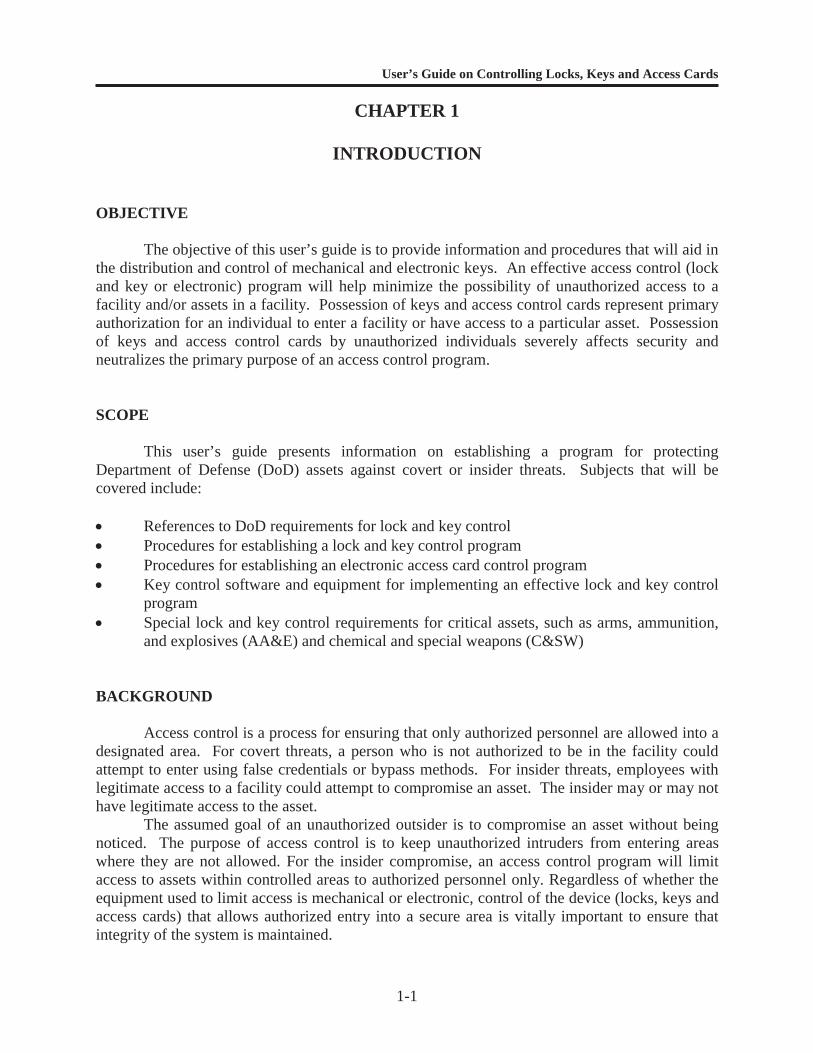
The objective of this user’s guide is to provide information and procedures that will aid inthe distribution and control of mechanical and electronic keys. An effective access control (lockand key or electronic) program will help minimize the possibility of unauthorized access to afacility and/or assets in a facility. Possession of keys and access control cards represent primaryauthorization for an individual to enter a facility or have access to a particular asset. Possessionof keys and access control cards by unauthorized individuals severely affects security andneutralizes the primary purpose of an access control program.
SCOPE
This user’s guide presents information on establishing a program for protectingDepartment of Defense (DoD) assets against covert or insider threats. Subjects that will becovered include:
References to DoD requirements for lock and key control Procedures for establishing a lock and key control program Procedures for establishing an electronic access card control program Key control software and equipment for implementing an effective lock and key control
program Special lock and key control requirements for critical assets, such as arms, ammunition,
and explosives (AA&E) and chemical and special weapons (C&SW)
BACKGROUND
Access control is a process for ensuring that only authorized personnel are allowed into adesignated area. For covert threats, a person who is not authorized to be in the facility couldattempt to enter using false credentials or bypass methods. For insider threats, employees withlegitimate access to a facility could attempt to compromise an asset. The insider may or may nothave legitimate access to the asset.
The assumed goal of an unauthorized outsider is to compromise an asset without beingnoticed. The purpose of access control is to keep unauthorized intruders from entering areaswhere they are not allowed. For the insider compromise, an access control program will limitaccess to assets within controlled areas to authorized personnel only. Regardless of whether theequipment used to limit access is mechanical or electronic, control of the device (locks, keys andaccess cards) that allows authorized entry into a secure area is vitally important to ensure thatintegrity of the system is maintained.
User’s Guide on Controlling Locks, Keys and Access Cards
1-2
Levels of Protection
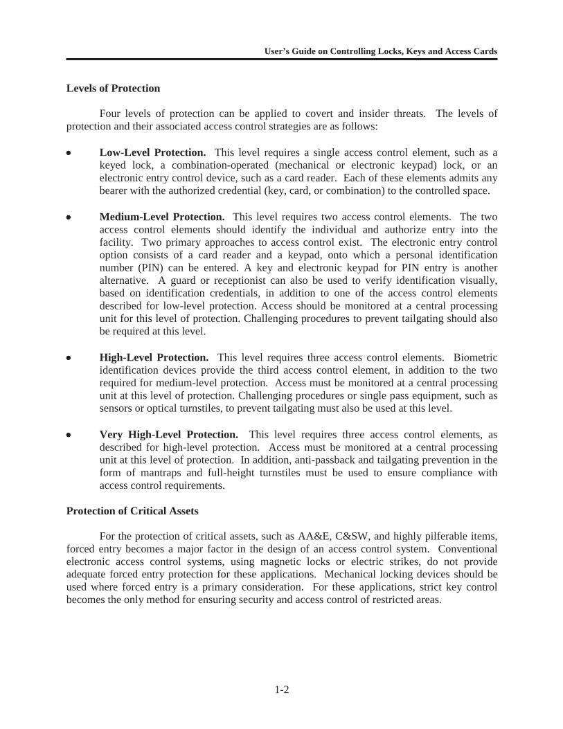
Four levels of protection can be applied to covert and insider threats. The levels ofprotection and their associated access control strategies are as follows:
Low-Level Protection. This level requires a single access control element, such as akeyed lock, a combination-operated (mechanical or electronic keypad) lock, or anelectronic entry control device, such as a card reader. Each of these elements admits anybearer with the authorized credential (key, card, or combination) to the controlled space.
Medium-Level Protection. This level requires two access control elements. The twoaccess control elements should identify the individual and authorize entry into thefacility. Two primary approaches to access control exist. The electronic entry controloption consists of a card reader and a keypad, onto which a personal identificationnumber (PIN) can be entered. A key and electronic keypad for PIN entry is anotheralternative. A guard or receptionist can also be used to verify identification visually,based on identification credentials, in addition to one of the access control elementsdescribed for low-level protection. Access should be monitored at a central processingunit for this level of protection. Challenging procedures to prevent tailgating should alsobe required at this level.
High-Level Protection. This level requires three access control elements. Biometricidentification devices provide the third access control element, in addition to the tworequired for medium-level protection. Access must be monitored at a central processingunit at this level of protection. Challenging procedures or single pass equipment, such assensors or optical turnstiles, to prevent tailgating must also be used at this level.
Very High-Level Protection. This level requires three access control elements, asdescribed for high-level protection. Access must be monitored at a central processingunit at this level of protection. In addition, anti-passback and tailgating prevention in theform of mantraps and full-height turnstiles must be used to ensure compliance withaccess control requirements.
Protection of Critical Assets
For the protection of critical assets, such as AA&E, C&SW, and highly pilferable items,forced entry becomes a major factor in the design of an access control system. Conventionalelectronic access control systems, using magnetic locks or electric strikes, do not provideadequate forced entry protection for these applications. Mechanical locking devices should beused where forced entry is a primary consideration. For these applications, strict key controlbecomes the only method for ensuring security and access control of restricted areas.
User’s Guide on Controlling Locks, Keys and Access Cards
1-3
APPROACH
The approach used in this user’s guide is to describe a program that addresses identifiedthreats and describes software and hardware that can be used to implement a program that willeffectively control locks and keys or access cards. Possession of keys and access control cards orcredentials by an employee represent authorization given by the command to have access to afacility or area within the facility. In the control of access, the key and access cards providesimilar functions in that they represent the same authority to enter and must be protected againstloss or compromise.
Both mechanical and electronic access control systems have advantages anddisadvantages in the control of access. Keys and access cards are different in terms of the levelof sophistication required for duplication. Keys can be mechanically duplicated while accesscards must be electronically read and duplicated. Both however are vulnerable to theft. Accesscards have the advantage of requiring secondary credentials such as personal identificationnumbers or biometric verification that is not possible with mechanical key systems. On the otherhand, mechanical keys that have a high level of resistance to picking and bypassing can providea higher level of physical protection against entry attack than electronic systems that rely onsolenoid actuated or magnetic locks.
The user’s guide is divided into five chapters and seven appendices that describe aprocess for controlling locks, keys and access cards or credentials. Chapter 2 describes DoDrequirements for access control. Chapter 3 provides a structured program for controlling locks,keys and access control cards. Chapter 4 provides descriptions of software and hardware that arecommercially available for controlling locks and keys. Chapter 5 provides a structured programthat specifically addresses the control of locks and keys that protect critical assets. Theappendices include a glossary of lock, key, and access control terms, references, a listing ofmanufacturers that offer software and hardware for access control, and forms that can be used toimplement a comprehensive lock, key, or access card control program. The appendices alsoinclude a checklist for lock and key control, a sample lock and key control plan, and a generaldescription of electronic access control systems.
User’s Guide on Controlling Locks, Keys and Access Cards
2-1
CHAPTER 2
DOD LOCK AND KEY CONTROL REQUIREMENTS
INTRODUCTION
All branches of the military service have established requirements for lock and keycontrol to protect critical assets. References 1 through 11 in Appendix B provide specificrequirements for the protection of arms, ammunition, and explosives (AA&E) and chemical andspecial weapons (C&SW), as well as general requirements for access control of restricted areasand critical assets.
Requirements for the physical security of sensitive AA&E (Risk Categories I throughIV), including lock and key control, are covered in References 1, 2, and 5. C&SW requirementsare covered in References 4, 10, and 11. References 1 and 11 apply to the:
Office of the Secretary of Defense Military departments (Army, Navy, Air Force and Marine Corps) Chairman of the Joint Chiefs of Staff and Joint Staff Unified and specified commands Inspector General of the Department of Defense Defense agencies DoD field activities
References 2, 3, and 4 apply specifically to Navy activities. References 5, 6, and 10 applyspecifically to Army and Air Force activities. References 7 and 8 apply specifically to Air Forceactivities.
REQUIREMENTS
Effective lock and key control programs are required for the protection of critical assetsand restricted areas. Comprehensive lock and key control programs are mandatory for theprotection of specific critical assets, such as sensitive AA&E and C&SW.
User’s Guide on Controlling Locks, Keys and Access Cards
3-1
CHAPTER 3
ESTABLISHING A PROGRAM FOR CONTROLLING LOCKS,KEYS, OR ACCESS CREDENTIALS
INTRODUCTION
The primary purpose of a lock and key or access credential control system is to controlaccess to lock cores and keys or to access control credentials that permit access to a particularbuilding or structure.
Key and access control systems can be simple or complex, depending upon userrequirements. As a minimum, lock and key or access control systems require a key or credentialinventory, issue records, and a procedure for returning the key or access control credential oncethe user no longer needs it. When control of keys or access control credentials is abandoned orlost, re-establishing security can be time-consuming and expensive, especially for conventionallock and key systems.
It is the responsibility of the individual command to develop and implement a policy forcontrolling locks, keys and access credentials. An example of a typical instruction for generalsecurity and critical assets is shown in Appendix C. For general security, lock, key and accesscontrol is usually a part of a comprehensive security and loss prevention plan. For critical assetssuch as arms, ammunition and explosives (AA&E), control requirements are mandated byspecific instructions (see Chapter 2).
This chapter is divided into two sections. The first section deals with mechanical locksand keys used for access control, and the second deals with electronic systems that usecredentials, credential readers, and electronic locks for access control. See Appendix D for adescription of typical electronic access control systems.
MECHANICAL LOCKS AND KEYS
Personnel and Duties
Commands should assign responsibility for the lock and key control program to a specificindividual or group and define duties in writing.
Key Control Officer. The Key Control Officer (KCO) is responsible for the operationand general function of the command lock and key control program. The KCO typically reportsto the commander or vice commander of the facility on all matters related to the lock and keycontrol program. Specific duties should include:
Determining the location and category of all locks at a facility Determining the status of all keys currently in use Arranging key storage, including selecting containers, key rings, key tags, etc. Ensuring that all key storage containers are used properly and in accordance with
directives and instructions
User’s Guide on Controlling Locks, Keys and Access Cards
3-2
Identifying restricted or critical areas Recommending areas for enclave security and master keying Designating Key Custodians Establishing lock and core rotation schedules Establishing locations for code storage and, as available, computer program acquisition
for lock and key code control Identifying qualified locksmith(s) for use by command Developing log procedures and forms for daily use Ensuring that lock and key procedures are known throughout the command through
educational programs
If lock and key systems protect critical assets or controlled areas, the individual assignedthe duties of a KCO should have a security clearance equivalent to the classification of thematerial or area being protected. Commands usually find it expedient to assign KCO duties tothe command Security Manager/Officer because there are close ties to emergency services andcommand and control operations.
Key Custodian. The Key Custodian reports directly to the KCO for direction andimplementation of the command’s lock and key control program. Duties include:
Conducting a quarterly inventory of custodial and sub-custodial key accounts Maintaining key control logbooks or computer records Meeting periodically with all Key Sub-Custodians to review key logs or records, discuss
rotation schedules, disseminate command educational program information, and resolvelock and key control problems
Assisting with the implementation of command policy on lock and key control Covering all other assignments relating to lock and key control, as designated by the
KCO
The Key Custodian designated by the KCO should have a security clearance equivalentto the classification of the material or area being protected.
Key Sub-Custodians. Key Sub-Custodians are selected by a command subdivision ortenant command and approved by the KCO. The Key Sub-Custodian is assigned control of oneor more keys, depending on requirements. For example, the fire department may be designatedas a Key Sub-Custodian and may have access to all keys at a particular command. Subdivisionsof the command may be sub-custodians when the subdivision requires different key applicationsthan the rest of the command. Sub-Custodians should have a security clearance equivalent to theclassification of the material or area being protected.
The Key Sub-Custodian reports directly to the Key Custodian for:
All assigned keys, including master keys or change keys if required Proper logging of change keys Verification of key usage
User’s Guide on Controlling Locks, Keys and Access Cards
3-3
Monthly key inventories Attendance at monthly meetings with the Key Custodian Other assigned tasks relating to lock and key control at the command subdivision level
Locksmith. A locksmith can help develop a workable key control program. Locksmithsare sometimes in a position to see the day-to-day operations from a working level and can helpidentify and implement workable procedures. At large commands, the locksmith shop issometimes a division within the security department. This arrangement makes it easier to:
Provide direct assistance to users without additional organizational layers Initiate timely lockout investigations and emergency access Implement lock and key rotation programs Provide security training to the command
If a locksmith is part of a key control program, some considerations should include:
Equipment. Modern locksmithing equipment, such as key cutting and core-assemblyequipment, will increase productivity and improve quality. Computers can make thelocksmith’s work easier through the use of key code, key control, and master-keyingprograms that can improve accuracy, increase productivity, and reduce the possibility ofcompromised lock and key codes. Computers can also be used for precision andautomatic key cutting. A clean and well-lit workspace with adequate room will aid in theprecision work required of a locksmith.
Education. A command locksmith should be adequately trained on the latest DoD policyand industry lock and key practices. Education can benefit the command throughincreased productivity, improved quality, and a broader range of service capabilities.Attendance at conferences, seminars, and classes should be included in the budget.
Staffing. Staffing requirements depend on the daily schedule of re-keying, emergencyaccess calls, lockouts, and lock rotation requirements. Adequate staffing will help ensuresuccessful program execution. Commands may want to consider assigning swing orgraveyard shifts for locksmiths to allow more time for administrative work, re-coring,and rotation efforts without the pressures of emergency calls, daytime work distractions,and disruption of the daytime workforce.
Contracting with a civilian locksmith service can increase the productivity of asmall staff and improve emergency response. Civilian locksmith services should bebonded and have security clearances as required by DoD and local policy. The contractagreement for civilian locksmith services needs to contain requirements for adherence toall command lock and key control policies and procedures.
Key Control Training
A program should be developed to train command personnel in lock and key controlprocedures and responsibilities. Training should be comprehensive and provide a strategic

User’s Guide on Controlling Locks, Keys and Access Cards
3-4
understanding of how lock and key control can affect the security of a command. Trainingshould include the following topics:
How to minimize the risk of a lock compromise Lock maintenance requirements Lock and key control procedures What to do in case of a lockout Proper key security, including procedures for dealing with lost, missing, stolen, or
damaged keys
Training programs should be designed to hold the attention of attendees. Use examplesand scenarios that describe real situations and problems (e.g., thefts that have taken place orcareless acts that can compromise a key control program). Diagrams, videos, pictures, or chartscan be used to illustrate the subject and make the training more interesting. Regardless of themethod, constant training of command personnel is essential to a successful lock and key controlprogram.
Facility Evaluation
Before initiating a lock and key control program, the KCO, the Key Custodian, and theKey Sub-Custodians should survey all lock locations throughout the facility with emphasis on:
Priority of assets protected Requirements for access to the assets Lock/core rotation and re-keying schedules Enclaving and master-keying requirements Status of lock and key control training Schedules for periodic meetings to make reevaluations Requirements by tenant commands or command subdivisions for lock and key support Established agency requirements and policies (see Chapter 2)
Procedures
Key Control Centers (KCC). At large commands, a KCC should be established wheredaily key issue and recording activities take place. If possible, co-locate the KCC with a 24-hourstaffed site, such as an emergency services or dispatch center. The KCC should have adequatepersonnel cleared at the appropriate classification level to provide lock and key control services.The key issue point should be located where it will not interfere with normal operations. TheWatch Officer during each shift should account for all controlled keys and maintain a chain-of-custody log. Activities at the KCC should include:
Key Issue. The KCC should control access to any key other than a personally assignedchange key. Personnel requiring the use of a key should be designated in a Key AccessLog (for descriptions of logs see Records Management in this chapter and Appendix E).The Key Access Log should be accessible only to KCC duty personnel. Separate key
User’s Guide on Controlling Locks, Keys and Access Cards
3-5
control logs should be used for issues and returns. Compare the signature on the KeyControl Log with the signature on the Key Access Log.
Bring any deviations from normal patterns to the attention of the KCO. Undernormal circumstances a master, restricted, or sensitive material control key should notleave the facility or remain with any person during the day or overnight.
Key-Making. Duplicate keys, key blanks, padlocks, lock cylinders and cores, key-making equipment, and key codes should be stored in a Central Key Room. Accessshould be limited to the base Commander, KCO, Key Custodian, and locksmith. TheCentral Key Room must always be secured when not in use. Key blanks and duplicatekeys have the same classification and require the same protection as original keys. Atcommands too small to justify a Central Key Room, a General Services Administration(GSA)-approved security container can be used to protect duplicate keys, blanks, keycodes, and associated equipment.
Key and Core Code Storage. Maintain codes for keys and lock cylinders or cores in theCentral Key Room. Keep these codes in an approved security container with accesslimited to the KCO and locksmith. Treat code information in the same manner asclassified documents. Do not allow unauthorized viewing or copying of thesedocuments.
Master-Keying. The term “master-keying” is used to describe a method of pinning aspecific set of lock cylinders so they operate with an individual key as well as a common key,called a “master.” A “set” of master-keyed cylinders could be as small as two locks or as largeas several thousand. Large master-key systems usually offer numerous levels to allow flexibilityand security.
Professionally designed and maintained master-key systems can be very effective atsaving time and money. Such systems are tailored to the objectives and operation of theorganization. Systems can be set up so each major component of the organization is covered bya segment of the overall system. This allows the designer to “build-in” room for expansion orarea re-keying, without affecting the rest of the system.
Effective master-key systems minimize the number of keys each employee needs to gainaccess to authorized spaces and equipment. Issuing low-level master keys gives the securityofficer the ability to limit the number of keys issued and also allows access to only those locksthe employee needs to open. Higher level master keys need to be strictly controlled and shouldonly be issued if absolutely necessary.
Key control is critical to a successful master-key system. If a top-level master key is lostor stolen, the entire facility may need to be re-keyed. This is expensive and time consuming. Ifa low-level master key is lost or stolen, only the locks that operated with that key would need tobe re-keyed.
Although master-key systems are proven to save time and money, they should not beused in all cases. Security officers need to be involved in the design and decision processes.Master-keying is primarily used in unclassified administrative spaces. High security locks andlocks used to protect classified or high value assets should never be master-keyed.
User’s Guide on Controlling Locks, Keys and Access Cards
3-6
Personnel designated to establish and/or maintain a master-key system need to be trainedand qualified to perform that function. Master-key and key control training courses are availablethrough professional locksmith organizations.
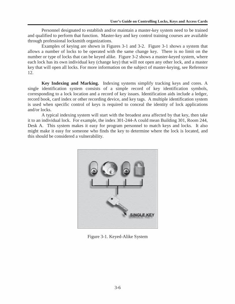
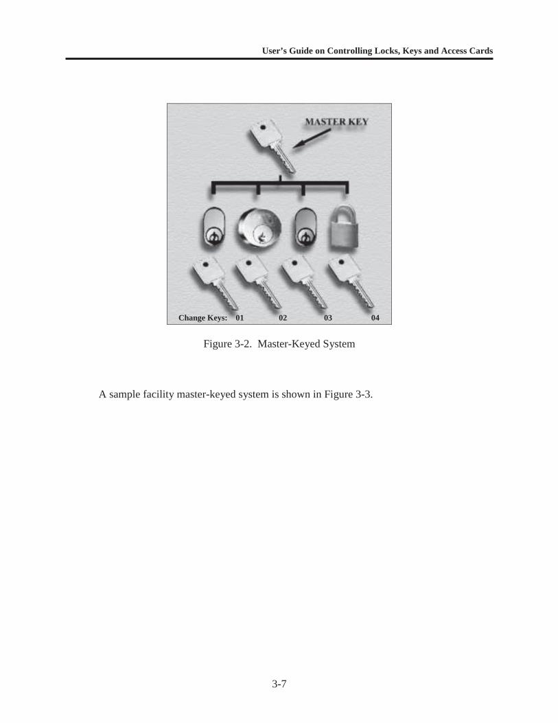
Examples of keying are shown in Figures 3-1 and 3-2. Figure 3-1 shows a system thatallows a number of locks to be operated with the same change key. There is no limit on thenumber or type of locks that can be keyed alike. Figure 3-2 shows a master-keyed system, whereeach lock has its own individual key (change key) that will not open any other lock, and a masterkey that will open all locks. For more information on the subject of master-keying, see Reference12.
Key Indexing and Marking. Indexing systems simplify tracking keys and cores. Asingle identification system consists of a simple record of key identification symbols,corresponding to a lock location and a record of key issues. Identification aids include a ledger,record book, card index or other recording device, and key tags. A multiple identification systemis used when specific control of keys is required to conceal the identity of lock applicationsand/or locks.
A typical indexing system will start with the broadest area affected by that key, then takeit to an individual lock. For example, the index 301-244-A could mean Building 301, Room 244,Desk A. This system makes it easy for program personnel to match keys and locks. It alsomight make it easy for someone who finds the key to determine where the lock is located, andthis should be considered a vulnerability.
Figure 3-1. Keyed-Alike System
User’s Guide on Controlling Locks, Keys and Access Cards
3-7
Figure 3-2. Master-Keyed System
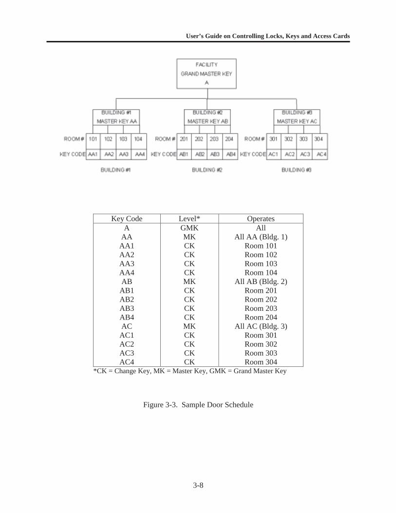
A sample facility master-keyed system is shown in Figure 3-3.
Change Keys: 01 02 03 04
User’s Guide on Controlling Locks, Keys and Access Cards
3-8
Key Code Level* OperatesA
AAAA1AA2AA3AA4ABAB1AB2AB3AB4ACAC1AC2AC3AC4
GMKMKCKCKCKCKMKCKCKCKCKMKCKCKCKCK
AllAll AA (Bldg. 1)
Room 101Room 102Room 103Room 104
All AB (Bldg. 2)Room 201Room 202Room 203Room 204
All AC (Bldg. 3)Room 301Room 302Room 303Room 304
*CK = Change Key, MK = Master Key, GMK = Grand Master Key
Figure 3-3. Sample Door Schedule
User’s Guide on Controlling Locks, Keys and Access Cards
3-9
A more complex indexing system is used when greater control of keys is required. Thissystem might use random or sequential numbers on keys. The index numbers are recorded in theKey Inventory Log along with the core or cylinder numbers. The tightly controlled KeyInventory Log then becomes the only source of information matching a key with a core orcylinder.
Index code numbers, as well as an index of all locks and keys, should always be secured.These records are typically kept in a GSA-approved security container in the Central Key Room.
For ease of locating the proper key, key tags may be marked with explicit locations andthe index number stamped on the key. The tag should not be issued to the user.
Records Management. Lock and key control software, as well as paper-based systems,are available for record management.
Paper-Based System. Traditional lock and key control record management systems usehandwritten documents. Logs and forms can be customized by individual commands fortheir specific use. Appendix E contains examples of logs that provide the requiredinformation. Bound logs are recommended to reduce the possibility of record tampering.Accurate documentation is critical in maintaining the physical security of an installation.Most paper-based systems include the following:
1. The Key Inventory Log (Table E-1 in Appendix E) tracks keys, lock cylinders andincludes: The key index code and corresponding lock core/cylinder index code(s) The location(s) of the locks opened by that key
2. The Key Access Log (Table E-2 in Appendix E) tracks personnel who haveaccess to keys and includes: Name and department code Office and home phone numbers Employee/military ID number Signature (for purposes of comparison)
3. The Key Control Log (Table E-3 in Appendix E) tracks key usage and includes: The date and time a key is issued The serial numbers and total number of keys issued The person receiving the issued key The person issuing the key The time and date when key is returned The person receiving the returned key
4. The Key Issue Record (Table E-4 in Appendix E) provides an audit trail for keyassignment and includes: Name Employee/Military ID number Number of keys issued
User’s Guide on Controlling Locks, Keys and Access Cards
3-10
Applicable building number, floor, room number, container, cage, sectionor area
Statement of responsibility (see Table E-4 for description of statement)
5. The Key Manufacturing Request (Table E-5 in Appendix E) provides an audittrail for making keys and includes: Requester Number of keys required Justification for the request Location of the lock Authorization for the request
6. The Lock Repair/Service Request (Table E-6 in Appendix E) provides an audittrail for repairing and servicing locks and includes: Requester Location of the lock Description of the problem Resolution of the problem
Lock and Key Control Software. Paper-based key control systems are time consumingand expensive. Lock and key control software is available that can track keys and usersand produce reports, such as total keys in the system, users, locations, and check-out/check-in data, etc. Programs are also available to assist with core/lock rotation andmaintenance, pinning codes, cylinder/core locations, and key-bitting codes and data. Amore complete description of commercially available software developed specifically forlock and key control is included in Chapter 4.
Equipment. A wide variety of equipment is commercially available for storing andtagging keys. For a description of these items, see Chapter 4.
Emergency-Use Keys. Emergency access to all buildings and gates is a requirement forlife safety. Delay in access to a facility or area could greatly increase damage or endangeroccupants or emergency service personnel. For this reason, consider designating fire andsecurity departments as facility Key Sub-Custodians. Co-locating fire and security dispatchservices (including the KCC) at the fire department could eliminate the need for issuing duplicatemaster keys to both emergency services.
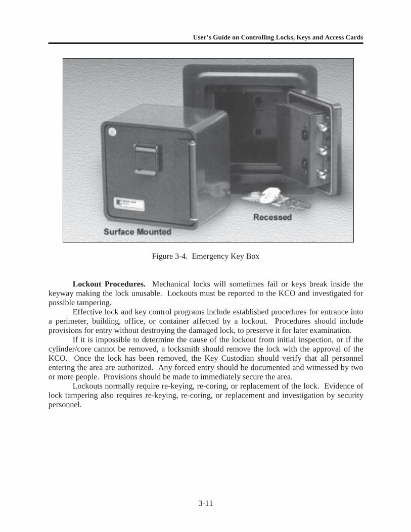
In those instances where security becomes the overriding consideration, commands maychoose to have emergency services gain entry by force. This can be difficult, dangerous, andtime consuming, particularly when high-security systems are in place. In a security situation,forced entry by the response force may jeopardize the lives of emergency personnel or buildingoccupants. One solution is an emergency lock box mounted outside a building (Figure 3-4). Itwill securely hold the keys to the building and can be opened only by emergency personnel.
User’s Guide on Controlling Locks, Keys and Access Cards
3-11
Figure 3-4. Emergency Key Box
Lockout Procedures. Mechanical locks will sometimes fail or keys break inside thekeyway making the lock unusable. Lockouts must be reported to the KCO and investigated forpossible tampering.
Effective lock and key control programs include established procedures for entrance intoa perimeter, building, office, or container affected by a lockout. Procedures should includeprovisions for entry without destroying the damaged lock, to preserve it for later examination.
If it is impossible to determine the cause of the lockout from initial inspection, or if thecylinder/core cannot be removed, a locksmith should remove the lock with the approval of theKCO. Once the lock has been removed, the Key Custodian should verify that all personnelentering the area are authorized. Any forced entry should be documented and witnessed by twoor more people. Provisions should be made to immediately secure the area.
Lockouts normally require re-keying, re-coring, or replacement of the lock. Evidence oflock tampering also requires re-keying, re-coring, or replacement and investigation by securitypersonnel.
User’s Guide on Controlling Locks, Keys and Access Cards
3-12
Supply Centers. The large number of locks needed for supply centers usually requiresenclaving and master keying. Areas highly subject to pilfering should be considered for rotationat least three times annually. Areas or facilities where access could be compromised byemployee turnover should consider supplemental methods of securing those areas, including useof antipilferage seals.
Personnel Termination. Cylinders should be re-keyed or locks re-cored when personnelare terminated. This is particularly important if the personnel had access to restricted areas.
Key Disposal. Used or obsolete keys should be controlled until properly destroyed.Keys should be destroyed in such a way that they cannot be used or copied. Using a metalgrinder to remove the key bitting is an effective method.
Lock Maintenance
Maintenance plays an important role in the operation of any lock. All locks andcylinders/cores should have a routine maintenance schedule. Locks exposed to natural elementsor harsh environments should receive more frequent maintenance.
A lock has many small parts. Lubrication is an important maintenance item to ensure thelocks will continue to work properly. Some fluid lubricants use a petroleum-based carrier thattends to hold dirt in the lock components, adversely affecting tolerances and causing prematurelock failure. Extremely low or high temperatures can make a lubricant gel freeze or thin, causingthe lock to fail or produce extreme wear that will lead to eventual failure. Always follow themanufacturer’s recommendations for maintenance and lubrication of locks.
Funding
Funding for lock and key control programs typically comes from the command operationand maintenance funds. Lock rotation programs must be balanced against available funding, butlack of funding should not restrict the program to the point where security is compromised.Assistance from the facility comptroller is helpful when planning a lock and key controlprogram.
Documentation
Document all lock and key control program procedures. Maintain written instructions forevery aspect of the program to make procedure standardization easier. Ensure that all programpersonnel are assigned duties in writing.
User’s Guide on Controlling Locks, Keys and Access Cards
3-13
ELECTRONIC ACCESS CONTROL SYSTEMS
Personnel and Duties
Identify the personnel involved in the access control program and define their duties.Avoid verbal orders; all personnel duties must be in writing. Efficient use of personnel can makea significant difference in the effectiveness of an access control program.
Access Control Officer (ACO). The ACO should be responsible for the operation andgeneral function of the access control program. The ACO typically reports to the commander orvice commander on all matters related to organizing the access control program. Specific dutiesinclude:
Determining the location and category of all access-controlled doors Determining the status of all access credentials currently issued Identifying areas of higher security requiring secondary credentials Recommending areas for possible enclave security Recommending credential reissue and recoding schedules Recommending locations for central processing and monitoring units Ensuring that access control procedures are known throughout the command through
educational programs Covering all other assignments relating to access control, as designated by the facility
commander
The ACO should have a security clearance equivalent to the classification of the materialor area being protected. The Security Officer/Manager is often selected as the ACO because ofthe close ties to emergency services and command and control operations.
Access Control Training
Develop programs to train personnel in access control program procedures andresponsibilities. The training should be comprehensive enough to provide a strategicunderstanding of how access control can affect the security of a command. Provide regulartraining on topics such as:
How access control systems work How to prevent defeat of access control systems How access control computer systems and software operate Maintenance methods Access control procedures Procedures for handling rejected credentials Proper access control security, including what to do if a credential is lost, missing, stolen,
or damaged
User’s Guide on Controlling Locks, Keys and Access Cards
3-14
Training programs should be designed to hold the attention of attendees. Use examplesand scenarios that describe real situations and problems (e.g., thefts that have taken place orcareless acts that can compromise a key control program). Diagrams, videos, pictures, or chartscan be used to illustrate the subject and make the training more interesting. Regardless of themethod, constant training is essential to a successful access control program.
Facility Evaluation
Prior to starting an access control program, the ACO should make a survey of all accesscontrol locations throughout the facility with emphasis on:
Priority of assets protected Requirements for access to the assets Access control credential reissue schedules Enclaving requirements Status of access control training Schedules for periodic meetings to re-evaluate requirements Requirements by tenant commands or command subdivisions for access control support
Procedures
Access Control Centers. For large commands with extensive electronic access controlrequirements, it may be necessary to establish an Access Control Center where the daily accesscontrol credential issuing and recording activities can take place. If possible, these centersshould be co-located with 24-hour staffed sites, such as emergency services dispatch centers.They should have adequate personnel to provide access control services. The access controlcredential issue point should be located where it will not interfere with emergency personnel,such as dispatchers or operators.
Blank access control credentials should be stored in a GSA-approved security containerwith access limited to the ACO and an alternate. Treat blank access control credentials in thesame manner as classified documents. Do not allow unauthorized access to blank credentials.
Records Management. Electronic access control systems normally include softwareprograms that allow the tracking and management of access control credentials. The data basemay contain information regarding badge authorization and can include badge number, employeenumber, name, address, telephone, motor vehicle registration, status, issue date, return date,authorization center, portal restrictions by time zones, entry/exit status, and trace. Acommentary section may also be included that is used for emergency call lists and other safety-related information. Computers containing personal and classified data of this nature should besecured at all times.
Lockout Procedures. When an electronic access control component (credential reader,electric strike, or magnetic lock) fails or a credential denies access to the user, the incident mustbe reported to the ACO.
An effective access control program should have established procedures for entrance intoa building or office when the access control system fails. Any forced entry or bypassing of the
User’s Guide on Controlling Locks, Keys and Access Cards
3-15
electric lock should be documented and witnessed by two or more people. The ACO shouldmake provisions to immediately secure the area. Access control system failure at the accessportal normally requires repair or replacement of the electric lock, strike, and/or reader.
Personnel Termination. Access codes should be immediately removed or canceledwhen personnel are terminated. This is particularly important if the personnel had access torestricted areas.
Access Control Credential Disposal. Used or obsolete access control credentials shouldbe controlled until properly destroyed, especially if they are also used as identification badges.Credentials should be destroyed in such a way that they cannot be used or copied. Using acrosscut shredder is a good method for destroying credentials.
Maintenance
Maintenance of credential readers is normally not required, other than periodic cleaningof the credential swipe path (not required for proximity sensors). Electric strikes require routineperiodic maintenance and lubrication, similar to mechanical locking devices. Magnetic locksrequire little maintenance. Credential readers and electric strikes exposed to natural elements orharsh environments should receive more frequent maintenance.
Funding
Funding for access control programs typically comes from the command operation andmaintenance fund. Software and data base maintenance should be balanced against availablefunding, but lack of funding must not restrict a program to the point where security iscompromised. Costs for periodic updates on access control software should be included in thebudget. Assistance from the facility comptroller is important when planning an effective accesscontrol program.
Documentation
Document all access control program procedures. Maintain written instructions for everyaspect of the program to make procedure standardization easier. Ensure that all programpersonnel are assigned duties in writing.
User’s Guide on Controlling Locks, Keys and Access Cards
4-1
CHAPTER 4
KEY CONTROL SOFTWARE AND EQUIPMENT
INTRODUCTION
This chapter contains a representative listing and description of locks, software andrelated equipment that can be used to establish an effective lock and key control program. Alisting of manufacturers and suppliers of this type of equipment and/or software is in AppendixF. This is not a complete list and any reference to a manufacturer is included only to illustratea piece of equipment or software. It is not intended to be a recommendation or anendorsement of any product or company.
KEY CONTROL SOFTWARE AND HARDWARE
Paper-based key control systems can be very time-consuming. Reports other than what iscontained on a single record sheet will require a significant amount of time to generate.
Computer-based programs track keys and users and produce reports, such as total keys inthe system, users, locations, and check-out/check-in data. Other programs are available to assistin core/lock rotation and maintenance, pinning/key bitting codes, and cylinder/core locations.Still others can interface with electronic locking systems to activate and deactivate locksremotely and provide specific access control for spaces and key storage.
Computerized record-keeping programs can store, arrange, search, and analyze data orautomatically produce reports based on the data. These programs typically have built-in reportforms that can be customized by the user and search features to isolate and arrange input datainto specialized formats. Special applications for use by AA&E facilities or supply centers arealso available. These programs can list keys by location hook numbers, as well as by locklocations. Additional programs link key-cutting machines directly to computers for cutting keys.
Tables 4-1 and 4-2 provide a brief description of commercially available hardware andsoftware that supports lock and key control programs.
User’s Guide on Controlling Locks, Keys and Access Cards
4-2
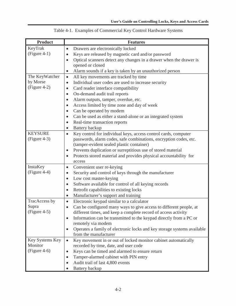
Table 4-1. Examples of Commercial Key Control Hardware Systems
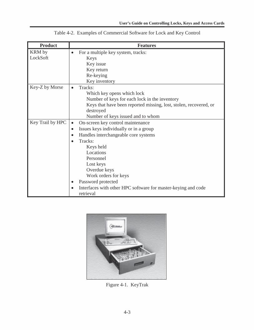
Product FeaturesKeyTrak(Figure 4-1)
Drawers are electronically locked Keys are released by magnetic card and/or password Optical scanners detect any changes in a drawer when the drawer is
opened or closed Alarm sounds if a key is taken by an unauthorized person
The KeyWatcherby Morse(Figure 4-2)
All key movements are tracked by time Individual user codes are used to increase security Card reader interface compatibility On-demand audit trail reports Alarm outputs, tamper, overdue, etc. Access limited by time zone and day of week Can be operated by modem Can be used as either a stand-alone or an integrated system Real-time transaction reports Battery backup
KEYSURE(Figure 4-3)
Key control for individual keys, access control cards, computerpasswords, alarm codes, safe combinations, encryption codes, etc.(tamper-evident sealed plastic container)
Prevents duplication or surreptitious use of stored material Protects stored material and provides physical accountability for
accessInstaKey(Figure 4-4)
Convenient user re-keying Security and control of keys through the manufacturer Low cost master-keying Software available for control of all keying records Retrofit capabilities to existing locks Manufacturer’s support and training
TracAccess bySupra(Figure 4-5)
Electronic keypad similar to a calculator Can be configured many ways to give access to different people, at
different times, and keep a complete record of access activity Information can be transmitted to the keypad directly from a PC or
remotely via modem Operates a family of electronic locks and key storage systems available
from the manufacturerKey Systems KeyMonitor(Figure 4-6)
Key movement in or out of locked monitor cabinet automaticallyrecorded by time, date, and user code
Keys can be timed and alarmed to ensure return Tamper-alarmed cabinet with PIN entry Audit trail of last 4,800 events Battery backup
User’s Guide on Controlling Locks, Keys and Access Cards
4-3
Table 4-2. Examples of Commercial Software for Lock and Key Control
Product FeaturesKRM byLockSoft
For a multiple key system, tracks:KeysKey issueKey returnRe-keyingKey inventory
Key-Z by Morse Tracks:Which key opens which lockNumber of keys for each lock in the inventoryKeys that have been reported missing, lost, stolen, recovered, ordestroyedNumber of keys issued and to whom
Key Trail by HPC On-screen key control maintenance Issues keys individually or in a group Handles interchangeable core systems Tracks:
Keys heldLocationsPersonnelLost keysOverdue keysWork orders for keys
Password protected Interfaces with other HPC software for master-keying and code
retrieval
Figure 4-1. KeyTrak
User’s Guide on Controlling Locks, Keys and Access Cards
4-4
Figure 4-2. The KeyWatcher
Figure 4-3. KEYSURE
User’s Guide on Controlling Locks, Keys and Access Cards
4-5
Figure 4-4. InstaKey
User’s Guide on Controlling Locks, Keys and Access Cards
4-6
Figure 4-5. TracAccess System
Figure 4-6. Key Systems Key Monitor
User’s Guide on Controlling Locks, Keys and Access Cards
4-7
MECHANICAL LOCK AND KEY SYSTEMS
Low-Security Locks and Cores
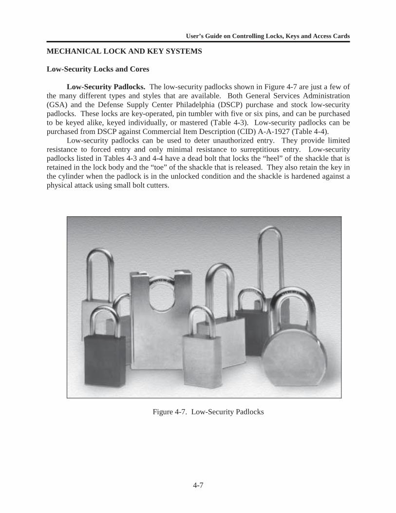
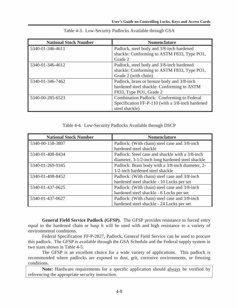
Low-Security Padlocks. The low-security padlocks shown in Figure 4-7 are just a few ofthe many different types and styles that are available. Both General Services Administration(GSA) and the Defense Supply Center Philadelphia (DSCP) purchase and stock low-securitypadlocks. These locks are key-operated, pin tumbler with five or six pins, and can be purchasedto be keyed alike, keyed individually, or mastered (Table 4-3). Low-security padlocks can bepurchased from DSCP against Commercial Item Description (CID) A-A-1927 (Table 4-4).
Low-security padlocks can be used to deter unauthorized entry. They provide limitedresistance to forced entry and only minimal resistance to surreptitious entry. Low-securitypadlocks listed in Tables 4-3 and 4-4 have a dead bolt that locks the “heel” of the shackle that isretained in the lock body and the “toe” of the shackle that is released. They also retain the key inthe cylinder when the padlock is in the unlocked condition and the shackle is hardened against aphysical attack using small bolt cutters.
Figure 4-7. Low-Security Padlocks
User’s Guide on Controlling Locks, Keys and Access Cards
4-8
Table 4-3. Low-Security Padlocks Available through GSA
National Stock Number Nomenclature5340-01-346-4611 Padlock, steel body and 3/8-inch hardened
shackle: Conforming to ASTM F833, Type PO1,Grade 2
5340-01-346-4612 Padlock, steel body and 3/8-inch hardenedshackle: Conforming to ASTM F833, Type PO1,Grade 2 (with chain)
5340-01-346-7462 Padlock, brass or bronze body and 3/8-inchhardened steel shackle: Conforming to ASTMF833, Type PO1, Grade 2
5340-00-285-6523 Combination Padlock: Conforming to FederalSpecification FF-P-110 (with a 3/8-inch hardenedsteel shackle)
Table 4-4. Low-Security Padlocks Available through DSCP
National Stock Number Nomenclature5340-00-158-3807 Padlock: (With chain) steel case and 3/8-inch
hardened steel shackle5340-01-408-8434 Padlock: Steel case and shackle with a 3/8-inch
diameter, 3-1/2-inch long hardened steel shackle5340-01-269-9345 Padlock: Brass body with a 3/8-inch diameter, 2-
1/2-inch hardened steel shackle5340-01-408-8452 Padlock: (With chain) steel case and 3/8-inch
hardened steel shackle - 10 Locks per set5340-01-437-0625 Padlock: (With chain) steel case and 3/8-inch
hardened steel shackle - 6 Locks per set5340-01-437-0627 Padlock: (With chain) steel case and 3/8-inch
hardened steel shackle - 24 Locks per set
General Field Service Padlock (GFSP). The GFSP provides resistance to forced entryequal to the hardened chain or hasp it will be used with and high resistance to a variety ofenvironmental conditions.
Federal Specification FF-P-2827, Padlock, General Field Service can be used to procurethis padlock. The GFSP is available through the GSA Schedule and the Federal supply system intwo sizes shown in Table 4-5.
The GFSP is an excellent choice for a wide variety of applications. This padlock isrecommended where padlocks are exposed to dust, grit, corrosive environments, or freezingconditions.
Note: Hardware requirements for a specific application should always be verified byreferencing the appropriate security instruction.
User’s Guide on Controlling Locks, Keys and Access Cards
4-9
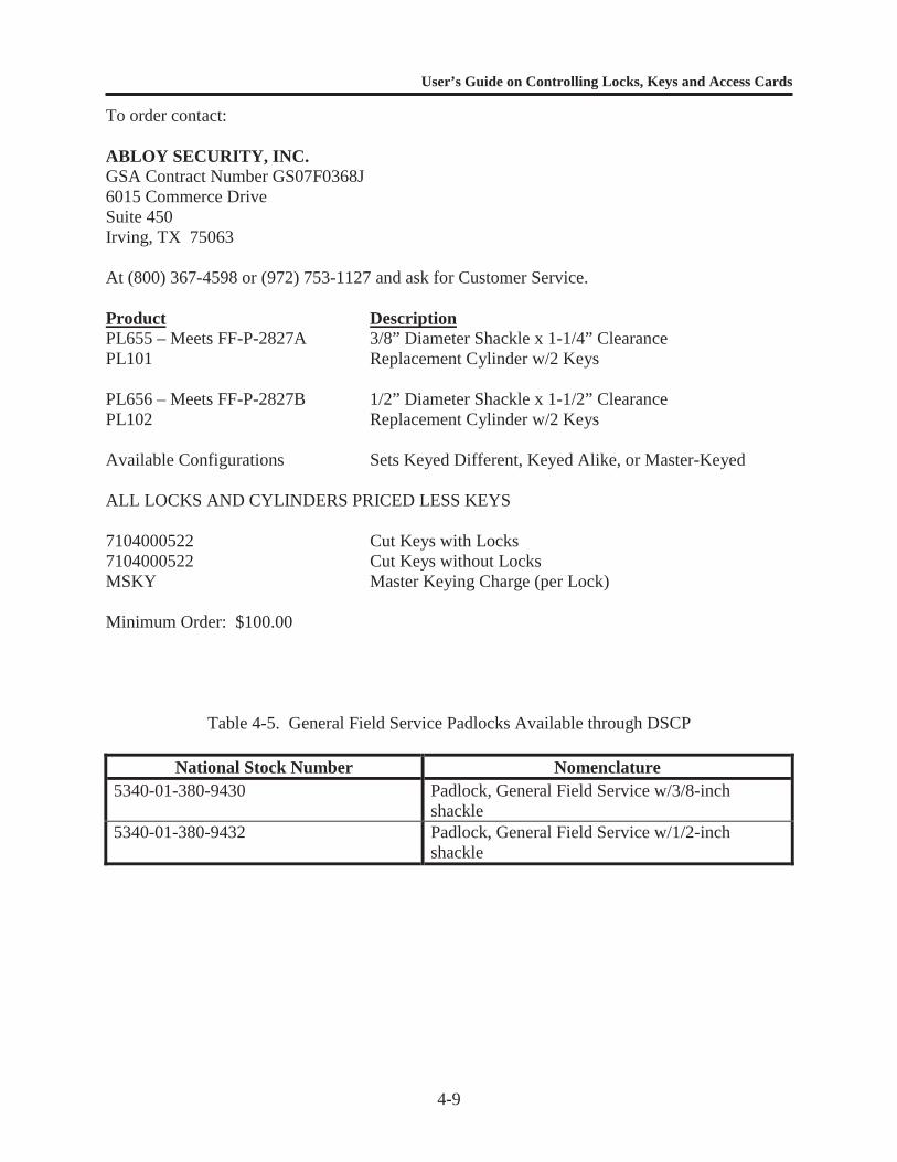
To order contact:
ABLOY SECURITY, INC.GSA Contract Number GS07F0368J6015 Commerce DriveSuite 450Irving, TX 75063
At (800) 367-4598 or (972) 753-1127 and ask for Customer Service.
Product DescriptionPL655 – Meets FF-P-2827A 3/8” Diameter Shackle x 1-1/4” ClearancePL101 Replacement Cylinder w/2 Keys
PL656 – Meets FF-P-2827B 1/2” Diameter Shackle x 1-1/2” ClearancePL102 Replacement Cylinder w/2 Keys
Available Configurations Sets Keyed Different, Keyed Alike, or Master-Keyed
ALL LOCKS AND CYLINDERS PRICED LESS KEYS
7104000522 Cut Keys with Locks7104000522 Cut Keys without LocksMSKY Master Keying Charge (per Lock)
Minimum Order: $100.00
Table 4-5. General Field Service Padlocks Available through DSCP
National Stock Number Nomenclature5340-01-380-9430 Padlock, General Field Service w/3/8-inch
shackle5340-01-380-9432 Padlock, General Field Service w/1/2-inch
shackle
User’s Guide on Controlling Locks, Keys and Access Cards
4-10
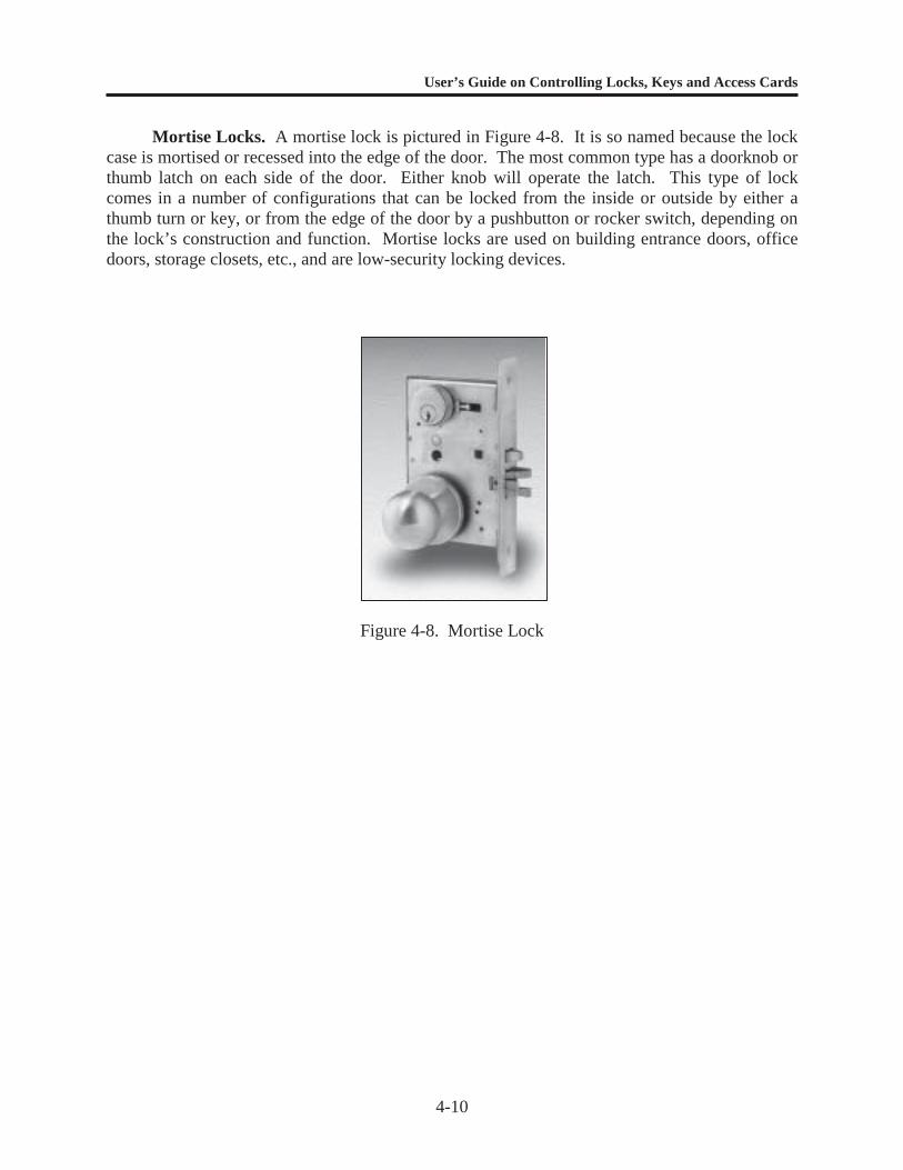
Mortise Locks. A mortise lock is pictured in Figure 4-8. It is so named because the lockcase is mortised or recessed into the edge of the door. The most common type has a doorknob orthumb latch on each side of the door. Either knob will operate the latch. This type of lockcomes in a number of configurations that can be locked from the inside or outside by either athumb turn or key, or from the edge of the door by a pushbutton or rocker switch, depending onthe lock’s construction and function. Mortise locks are used on building entrance doors, officedoors, storage closets, etc., and are low-security locking devices.
Figure 4-8. Mortise Lock
User’s Guide on Controlling Locks, Keys and Access Cards
4-11
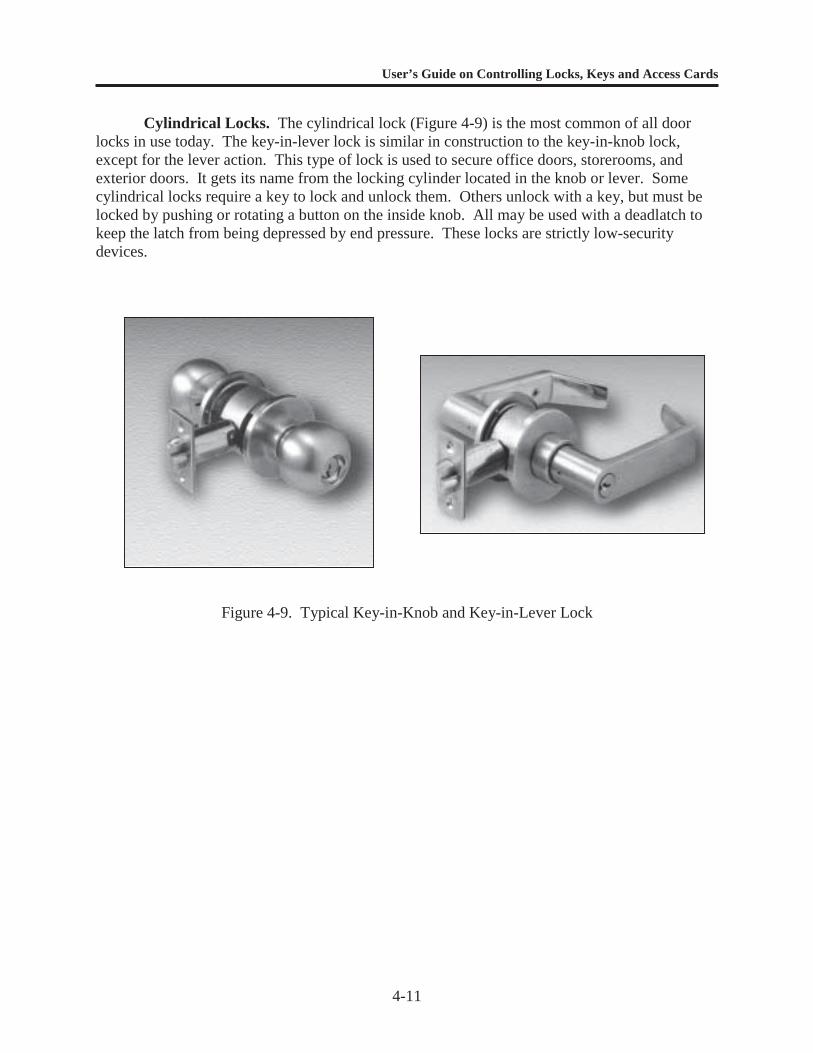
Cylindrical Locks. The cylindrical lock (Figure 4-9) is the most common of all doorlocks in use today. The key-in-lever lock is similar in construction to the key-in-knob lock,except for the lever action. This type of lock is used to secure office doors, storerooms, andexterior doors. It gets its name from the locking cylinder located in the knob or lever. Somecylindrical locks require a key to lock and unlock them. Others unlock with a key, but must belocked by pushing or rotating a button on the inside knob. All may be used with a deadlatch tokeep the latch from being depressed by end pressure. These locks are strictly low-securitydevices.
Figure 4-9. Typical Key-in-Knob and Key-in-Lever Lock

User’s Guide on Controlling Locks, Keys and Access Cards
4-12
Deadbolt Locks. The deadbolt lock (Figure 4-10), also referred to as a tubular deadbolt,is similar to the cylindrical lock in that it is mounted in a hole cut through the door. When thebolt is extended, force applied to the end of a deadbolt lock will not retract it. The deadbolt, usedin conjunction with a cylindrical lock, provides considerably greater security than a low-securitypadlock and hasp, if there is sufficient engagement of the bolt into the jamb (at least 1-inch).Single- and double-cylinder deadbolt locks are the two types most commonly used. A single-cylinder deadbolt has one cylinder facing the outside and is operated by a key. The inside isoperated with a thumb turn. This type is more secure when used if there are no windows in theproximity of the lock. The second type is a double-cylinder lock that has a cylinder on bothsides. This requires that a key be used to lock and unlock from either side of the door. This typeof lock is best used when nearby windows will provide easy access to the lock. Caution shouldbe used when selecting a double-cylinder lock to ensure that its use does not violate requirementsfor life safety.
Figure 4-10. Double-Cylinder Deadbolt Lock
User’s Guide on Controlling Locks, Keys and Access Cards
4-13
Interchangeable Core Systems
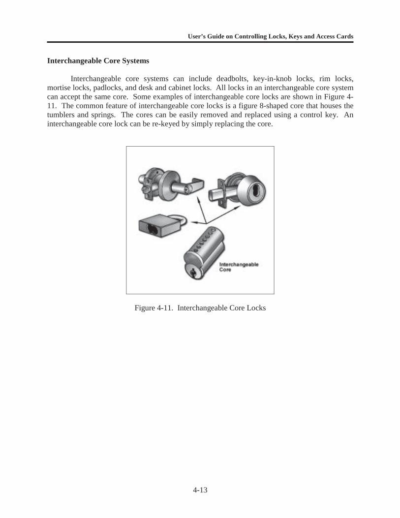
Interchangeable core systems can include deadbolts, key-in-knob locks, rim locks,mortise locks, padlocks, and desk and cabinet locks. All locks in an interchangeable core systemcan accept the same core. Some examples of interchangeable core locks are shown in Figure 4-11. The common feature of interchangeable core locks is a figure 8-shaped core that houses thetumblers and springs. The cores can be easily removed and replaced using a control key. Aninterchangeable core lock can be re-keyed by simply replacing the core.
Figure 4-11. Interchangeable Core Locks
User’s Guide on Controlling Locks, Keys and Access Cards
4-14
KEY STORAGE EQUIPMENT
General Key Storage
For key storage, use solidly constructed metal key storage containers. Wooden boardswith nail or hook arrangements do not offer security for key storage. It is best not to use exposedkey storage for any keys.
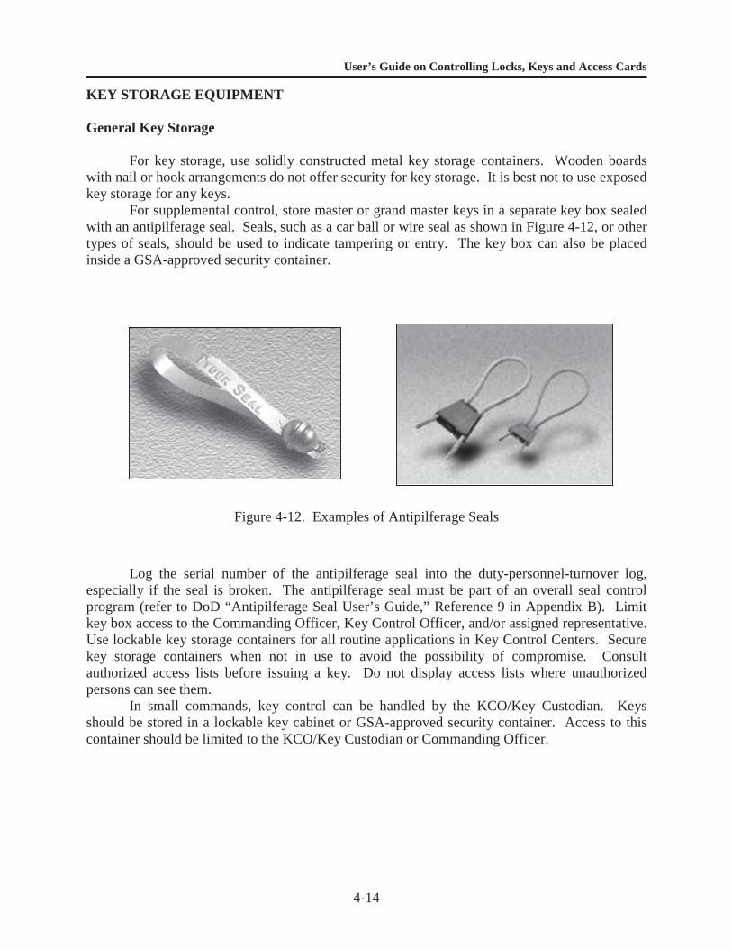
For supplemental control, store master or grand master keys in a separate key box sealedwith an antipilferage seal. Seals, such as a car ball or wire seal as shown in Figure 4-12, or othertypes of seals, should be used to indicate tampering or entry. The key box can also be placedinside a GSA-approved security container.
Figure 4-12. Examples of Antipilferage Seals
Log the serial number of the antipilferage seal into the duty-personnel-turnover log,especially if the seal is broken. The antipilferage seal must be part of an overall seal controlprogram (refer to DoD “Antipilferage Seal User’s Guide,” Reference 9 in Appendix B). Limitkey box access to the Commanding Officer, Key Control Officer, and/or assigned representative.Use lockable key storage containers for all routine applications in Key Control Centers. Securekey storage containers when not in use to avoid the possibility of compromise. Consultauthorized access lists before issuing a key. Do not display access lists where unauthorizedpersons can see them.
In small commands, key control can be handled by the KCO/Key Custodian. Keysshould be stored in a lockable key cabinet or GSA-approved security container. Access to thiscontainer should be limited to the KCO/Key Custodian or Commanding Officer.
User’s Guide on Controlling Locks, Keys and Access Cards
4-15
Key Cabinets, Lockers, and Safes
Selecting the proper key control cabinet depends upon its intended use in the system. Awide variety of key cabinets are available, including wall-mounted (flush or recessed), table-mounted, multiple-drawer, and portable. The capacity of these cabinets ranges from about 20keys for the smallest wall-mounted cabinet to over 3,300 keys for an 8-drawer cabinet.
Most standard key cabinets have the same type of lock as an office desk and provideapproximately the same minimal protection. Although dual combination locks and padlock-locking systems are available for key cabinets, they do not increase the overall securityprotection provided by the cabinet. Key cabinets should not be used for the storage of keys tosensitive materials. Such keys are to be stored in security containers, as required by applicablesecurity instructions.
Placement of the key cabinets within the facility is important. The cabinets should belocated within a room or building that is either locked or attended at all times. Keys to thecabinets should also be controlled.
Key cabinets are available with single and multiple identification systems. A singleidentification system provides only the lock labels, temporary key tags, and permanent key tags.A multiple identification system is a complete, cross-indexed system of records for recordingalphabetically the hook number, core number, core codes, and master-keying information.Complete key control systems include all necessary components, such as key-gatheringenvelopes, hook labels, temporary key tags, receipt holders, receipt forms, an index, and aninstructional manual.
The cabinets may be purchased separately, in which case only the cabinet and hook labelsare furnished. Accessories, such as tags and additional panels for expanding the capacity, maybe purchased with or for the above systems.
Lockable, wall-mounted key cabinets with key hooks, key tags, and a singleidentification system are described in detail by CID A-A-2547 and are available in the Federalsupply system.
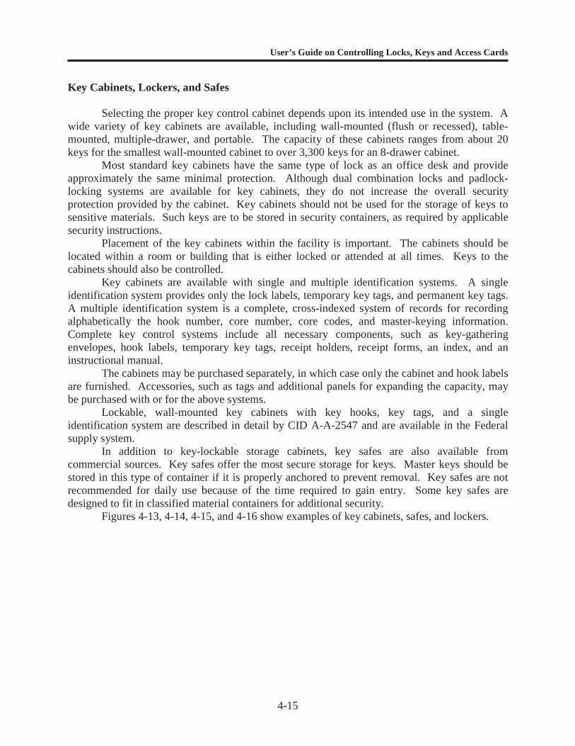
In addition to key-lockable storage cabinets, key safes are also available fromcommercial sources. Key safes offer the most secure storage for keys. Master keys should bestored in this type of container if it is properly anchored to prevent removal. Key safes are notrecommended for daily use because of the time required to gain entry. Some key safes aredesigned to fit in classified material containers for additional security.
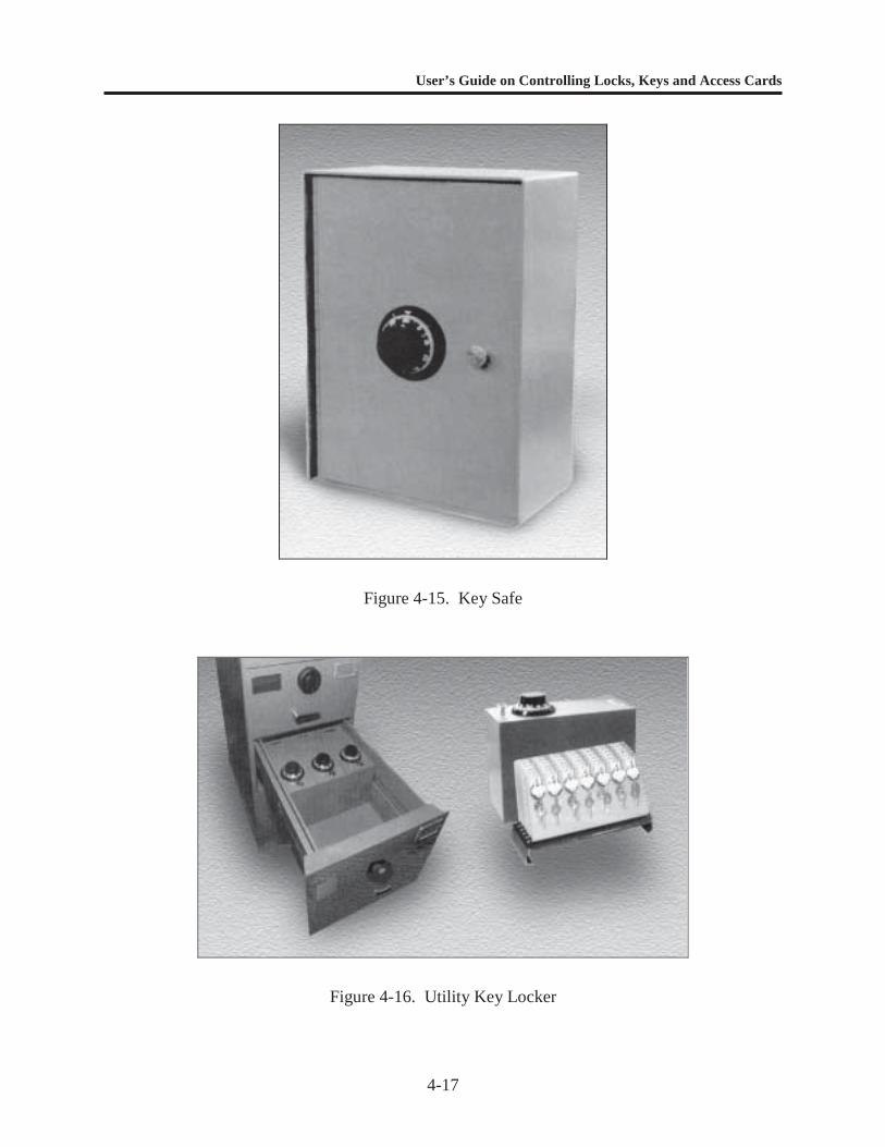
Figures 4-13, 4-14, 4-15, and 4-16 show examples of key cabinets, safes, and lockers.

User’s Guide on Controlling Locks, Keys and Access Cards
4-16
Figure 4-13. Key Cabinet
Figure 4-14. File Cabinet Insert
User’s Guide on Controlling Locks, Keys and Access Cards
4-17
Figure 4-15. Key Safe
Figure 4-16. Utility Key Locker

User’s Guide on Controlling Locks, Keys and Access Cards
4-18
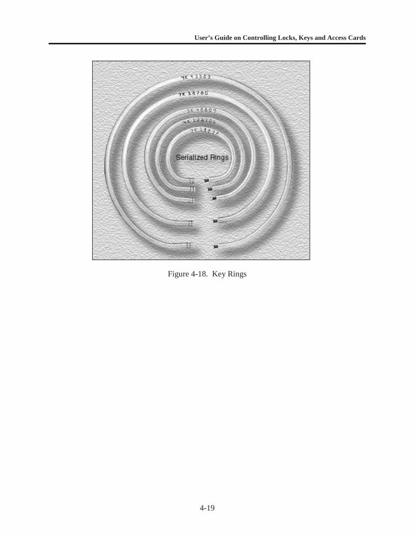
Key Tags and Key Rings
A system of indexing and tagging keys is crucial to an effective lock and key controlprogram. Choose key tags that are readily recognizable and easily readable. There are tagsavailable through the Federal supply system (NSN 9905-00-245-7826) that meet the criteria.Tagging systems are also available from the commercial sources (see Figure 4-17).
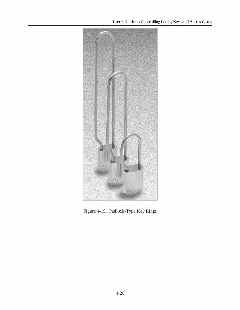
Select key rings that are resistant to accidental openings. If your level of securitywarrants it, choose one-time rings that must be destroyed to remove the keys. These rings mayalso be coded with serial numbers and designed to show evidence of tampering. One-time ringsare typically secured with a crimping tool. Figures 4-18 and 4-19 are examples of tamper-resistant key rings.
Figure 4-17. Key Tags
User’s Guide on Controlling Locks, Keys and Access Cards
4-19
Figure 4-18. Key Rings
User’s Guide on Controlling Locks, Keys and Access Cards
4-20
Figure 4-19. Padlock-Type Key Rings
User’s Guide on Controlling Locks, Keys and Access Cards
5-1
CHAPTER 5
LOCK AND KEY CONTROL FOR CRITICAL ASSETS
INTRODUCTION
Protection of critical assets, such as AA&E, C&SW, sensitive material or equipment, andhighly pilferable items, requires a structured and strict approach to key control. Protection ofthese assets is covered by References 1 through 11 in Appendix B.
SPECIFIC REQUIREMENTS
AA&E Facilities
1. Keys to areas protecting AA&E must be maintained separately from all other keys.2. Keys should only be issued to personnel from authorized access lists.3. Authorized access lists should not be available to unauthorized individuals.4. The number of keys issued for any single lock should be held to a minimum.5. Keys must never be left unattended.6. Keys must never be left unsecured.7. For Category III and IV AA&E, only designated key storage containers with at least 20-
gauge steel construction, an Underwriters Laboratories (UL) 768-listed, built-in, Group 1changeable combination lock or a GSA-approved combination padlock (Sargent andGreenleaf (S&G) Model 8077) shall be used.
8. Keys to Category I and II AA&E shall be stored in a Class 5 GSA-approved securitycontainer.
9. Keys must never leave the facility or remain with any one individual during operations orovernight.
10. High-security locks must be rotated or re-keyed at least annually or when keys are lost,misplaced, or stolen.
11. Replacement or reserve locks, cores, and keys shall be secured in designated key storagecontainers or a Class 5 GSA-approved container to prevent access by unauthorizedindividuals.
12. A lock on a storage facility must operate with only its own change key (no master keyingor keying alike is allowed).
13. A lock and key custodian must be appointed and designated in writing.14. A key control log must be maintained to ensure key accountability (Table E-3 in
Appendix E).15. Accountability records shall be retained for 90 days.16. Padlocks shall be locked to the staple or hasp when the area or container is open.17. Inventories of keys and locks shall be conducted semiannually.
User’s Guide on Controlling Locks, Keys and Access Cards
5-2
18. Positive, two-person control is recommended for all Category I through IV magazine andstorage entries, except in special cases, and then only in strict adherence to applicablerequirements.
C&SW Facilities
Key control for C&SW facilities applies to storage structures, buildings, rooms, andcontainers in both limited and exclusion areas, as well as keys to intrusion detection systems,perimeter gates, and manhole covers. In addition to the lock and key control requirements forAA&E, the following must be implemented for special weapons and Category I, II, and IIIchemical weapons:
1. Keys to C&SW storage facilities shall be controlled as classified material and stored in aClass 5 security container.
2. Keys must be maintained separately from all other keys.3. Keys and locks must be audited monthly.4. Keys shall be inventoried with each change of custody.5. Positive, two-person control is required for access to all C&SW storage facilities.6. Two-key entry (two separate locking systems or one locking system with two keys) is
mandatory to ensure compliance with the two-person requirement.
Sensitive and Highly Pilferable Material or Equipment
The following requirements apply:
1. Keys should never be left unattended.2. Keys should never be left unsecured.3. Commercial, lockable key storage containers should be used.4. Open storage of keys that are accessible to unauthorized individuals should be avoided.5. Keys should never leave the facility or routinely remain with any one individual during
operations or overnight.6. Access to keys should be made strictly from authorized access lists only.7. Authorized access lists should not be displayed where unauthorized individuals can view
them.
Designated Key Storage Containers
Containers designated for secure key storage (Table 5-1) must be made of 20-gauge steelor an equivalent-strength material (Figure 5-1). They must be equipped with a UL 768-listed,built-in, Group 1, changeable combination lock or modified to accept a GSA-approved, three-position, changeable combination padlock, S&G Model 8077, NSN 5340-00-285-6523 (Figure5-2).
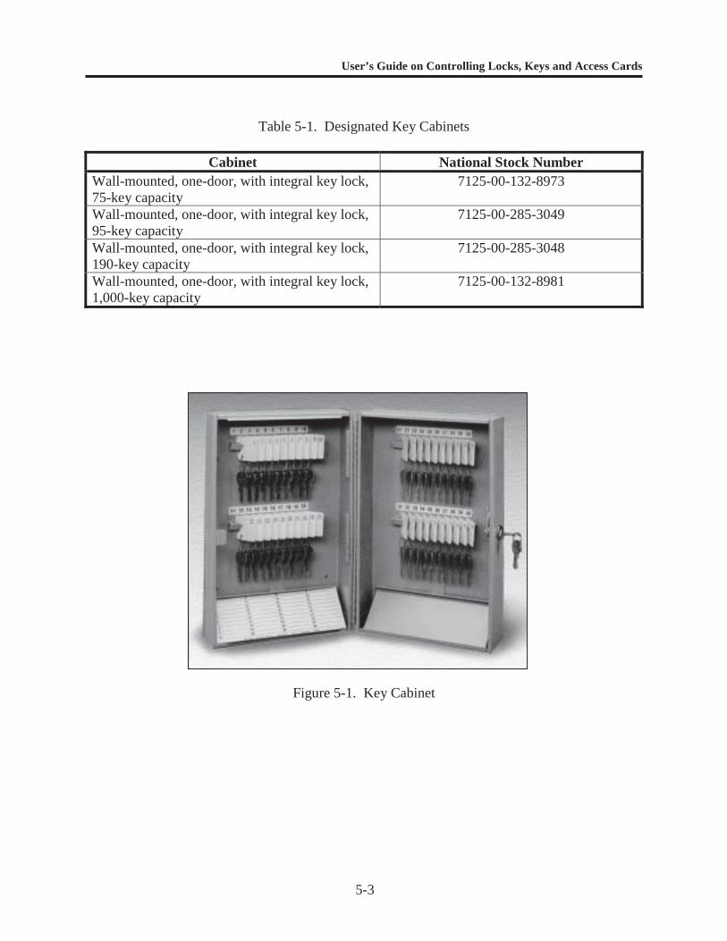
User’s Guide on Controlling Locks, Keys and Access Cards
5-3
Table 5-1. Designated Key Cabinets
Cabinet National Stock NumberWall-mounted, one-door, with integral key lock,75-key capacity
7125-00-132-8973
Wall-mounted, one-door, with integral key lock,95-key capacity
7125-00-285-3049
Wall-mounted, one-door, with integral key lock,190-key capacity
7125-00-285-3048
Wall-mounted, one-door, with integral key lock,1,000-key capacity
7125-00-132-8981
Figure 5-1. Key Cabinet
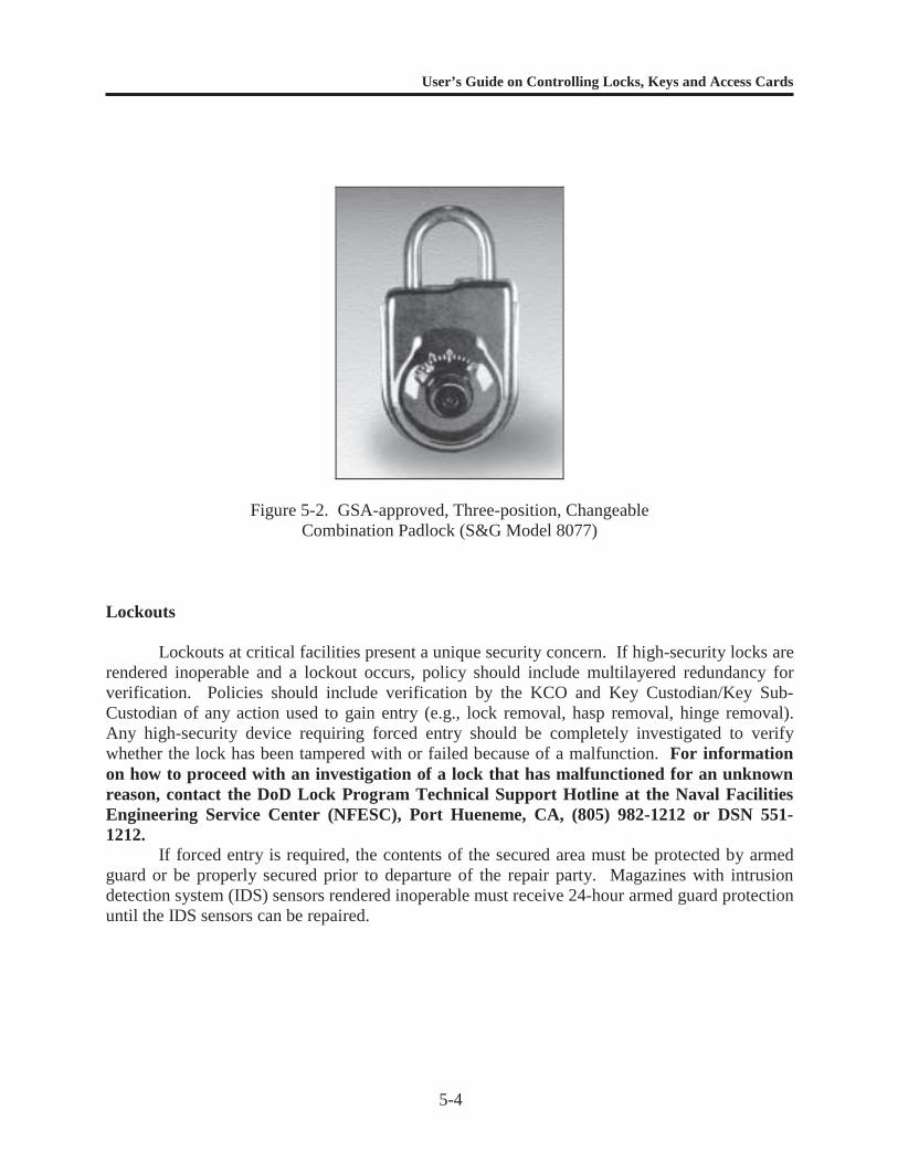
User’s Guide on Controlling Locks, Keys and Access Cards
5-4
Figure 5-2. GSA-approved, Three-position, ChangeableCombination Padlock (S&G Model 8077)
Lockouts
Lockouts at critical facilities present a unique security concern. If high-security locks arerendered inoperable and a lockout occurs, policy should include multilayered redundancy forverification. Policies should include verification by the KCO and Key Custodian/Key Sub-Custodian of any action used to gain entry (e.g., lock removal, hasp removal, hinge removal).Any high-security device requiring forced entry should be completely investigated to verifywhether the lock has been tampered with or failed because of a malfunction. For informationon how to proceed with an investigation of a lock that has malfunctioned for an unknownreason, contact the DoD Lock Program Technical Support Hotline at the Naval FacilitiesEngineering Service Center (NFESC), Port Hueneme, CA, (805) 982-1212 or DSN 551-1212.
If forced entry is required, the contents of the secured area must be protected by armedguard or be properly secured prior to departure of the repair party. Magazines with intrusiondetection system (IDS) sensors rendered inoperable must receive 24-hour armed guard protectionuntil the IDS sensors can be repaired.
User’s Guide on Controlling Locks, Keys and Access Cards
5-5
High-Security Lock Hardware
The following requirements apply:
Entry doors to armories and magazines storing AA&E or C&SW must be secured with ahigh-security locking system (Table 5-2). Interior doorways may use GSA-approvedClass 5 vault doors, equipped with a UL 768-listed, Group 1 combination lock.
Facilities where aircraft or vehicles are stored with weapons on board must be securedwith a high-security locking system, or equivalent compensatory measures.
Doors not normally used for entry must be secured from the inside with locking bars,deadbolts, or padlocks. Bolt-type seals or cable-type seals could also be used for thispurpose. Panic hardware, when required, must be installed to prevent opening the doorby drilling a hole and/or fishing from the outside. Panic hardware must meet life safety,fire, and building codes and be UL-listed or, when applicable, meet host countryrequirements.
Padlocks must be locked to the staple or hasp when a door or container is open topreclude theft, loss, or substitution of the lock.
For the Navy, Marine Corps and Coast Guard, the Naval Surface Warfare Center(NSWC), Crane Division, Crane, Indiana, issues, repairs, and replaces cylinders andlocks, and issues keys for S&G 833C high-security padlocks. Damaged ormalfunctioning locks and requests for cylinder and key replacement will be sent byregistered mail to Commanding Officer, Naval Surface Warfare Center Crane Division,300 Highway 361, Crane IN 47522-5060 [Code 7095] (telephone 812-854-1354 or 3354;DSN 482-1354 or 3354; FAX: 812-854-1074). Non-Navy customers interested in theseservices can call NSWC to discuss specific requirements and payment options.
Locks and/or lock cores should be rotated annually for security purposes.
A preventive maintenance (PM) program must be established and operated for all high-security locking systems. All high-security locks should receive PM once a year andmore often if subjected to severe environmental conditions (dust, sand, salt air, extremecold, etc.).
The NFESC is the DoD Locks, Safes, Vaults, Seals, and Containers Program TechnicalManager. Questions about any of these items may be directed to the DoD Lock ProgramTechnical Support Hotline 1-800-290-7607, commercial phone 805-982-1212, DSN 551-1212, E-mail [email protected] or Web Site HTTP://locks.nfesc.navy.mil .
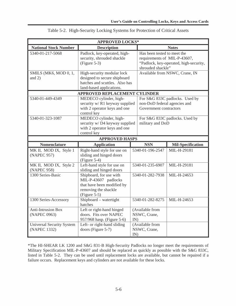
User’s Guide on Controlling Locks, Keys and Access Cards
5-6
Table 5-2. High-Security Locking Systems for Protection of Critical Assets
APPROVED LOCKS*National Stock Number Description Notes
5340-01-217-5068 Padlock, key-operated, high-security, shrouded shackle(Figure 5-3)
Has been tested to meet therequirements of MIL-P-43607,“Padlock, key-operated, high-security,shrouded shackle”
SMILS (MK6, MOD 0, 1,and 2)
High-security modular lockdesigned to secure shipboardhatches and scuttles. Also hasland-based applications.
Available from NSWC, Crane, IN
APPROVED REPLACEMENT CYLINDER5340-01-449-4349 MEDECO cylinder, high-
security w/ R1 keyway suppliedwith 2 operator keys and onecontrol key
For S&G 833C padlocks. Used bynon-DoD federal agencies andGovernment contractors
5340-01-323-1087 MEDECO cylinder, high-security w/ D4 keyway suppliedwith 2 operator keys and onecontrol key
For S&G 833C padlocks. Used bymilitary and DoD
APPROVED HASPSNomenclature Application NSN Mil-Specification
MK II, MOD IX, Style 1(NAPEC 957)
Right-hand style for use onsliding and hinged doors(Figure 5-4)
5340-01-196-2547 MIL-H-29181
MK II, MOD IX, Style 2(NAPEC 958)
Left-hand style for use onsliding and hinged doors
5340-01-235-6907 MIL-H-29181
1300 Series-Basic Shipboard, for use withMIL-P-43607 padlocksthat have been modified byremoving the shackle(Figure 5-5)
5340-01-282-7938 MIL-H-24653
1300 Series-Accessory Shipboard – watertighthatches
5340-01-282-8275 MIL-H-24653
Anti-Intrusion Box(NAPEC 0963)
Left or right-hand hingeddoors. Fits over NAPEC957/968 hasp. (Figure 5-6)
(Available fromNSWC, Crane,IN)
Universal Security System(NAPEC 1332)
Left- or right-hand slidingdoors (Figure 5-7)
(Available fromNSWC, Crane,IN)
*The HI-SHEAR LK 1200 and S&G 831-B High-Security Padlocks no longer meet the requirements ofMilitary Specification MIL-P-43607 and should be replaced as quickly as possible with the S&G 833C,listed in Table 5-2. They can be used until replacement locks are available, but cannot be repaired if afailure occurs. Replacement keys and cylinders are not available for these locks.
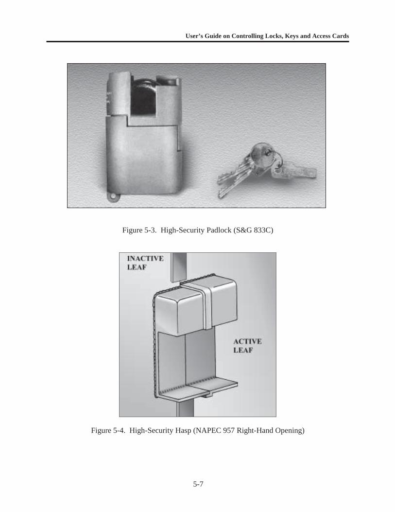
User’s Guide on Controlling Locks, Keys and Access Cards
5-7
Figure 5-3. High-Security Padlock (S&G 833C)
Figure 5-4. High-Security Hasp (NAPEC 957 Right-Hand Opening)
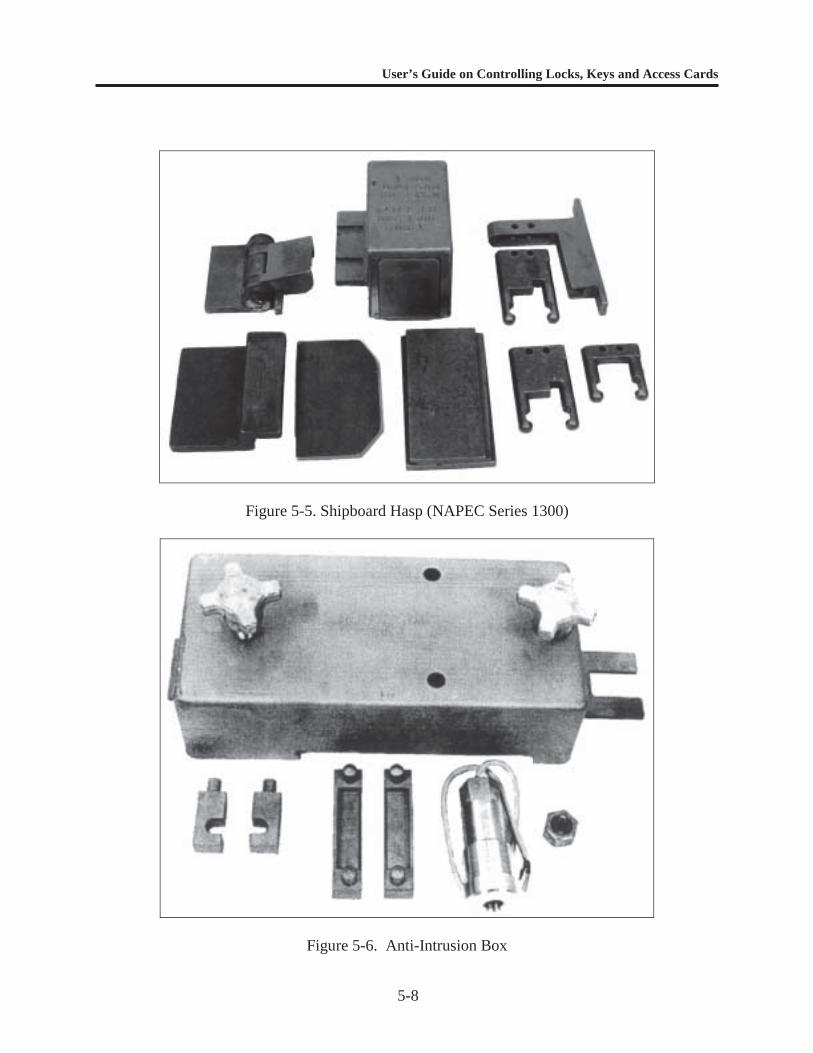
User’s Guide on Controlling Locks, Keys and Access Cards
5-8
Figure 5-5. Shipboard Hasp (NAPEC Series 1300)
Figure 5-6. Anti-Intrusion Box
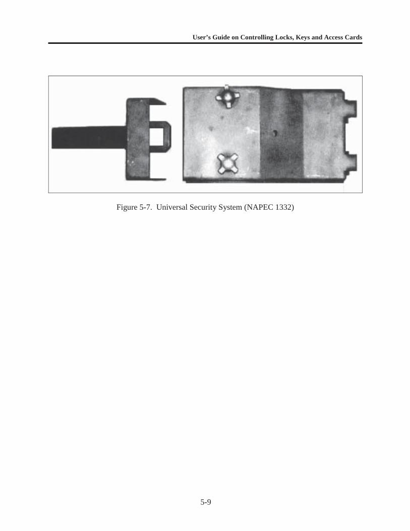
User’s Guide on Controlling Locks, Keys and Access Cards
5-9
Figure 5-7. Universal Security System (NAPEC 1332)
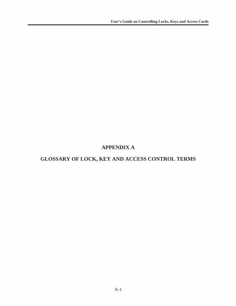
User’s Guide on Controlling Locks, Keys and Access Cards
A-1
APPENDIX A
GLOSSARY OF LOCK, KEY AND ACCESS CONTROL TERMS

User’s Guide on Controlling Locks, Keys and Access Cards
A-2
GLOSSARY OF COMMON LOCK AND KEY CONTROL TERMS
Access Control A method of controlling the movement of persons into or within aprotected area.
ANSI American National Standards Institute, the coordinator of the U.S.voluntary standards system. The system meets national standardsneeds by marshaling the competence and cooperation of commerceand industry, standards-developing organizations, and public andconsumer interests. ANSI specifications listed in this guide have beenadopted by the DoD.
Anti-Passback An access control software feature that prevents two individuals fromusing the same access control card to gain access at the same time (i.e.,first individual swipes card to gain access then passes the card to asecond individual for the same purpose).
ASTM American Society for Testing and Materials. From the work of 133technical standards-writing committees, ASTM publishes more than8,000 standards each year in 68 volumes of the Annual Book ofASTM Standards. The ASTM Committee F12 on Security Systemsand Equipment develops and standardizes terminology, test methods,specifications, performance specifications, classifications andpractices for security systems, components, and equipment referencedin this guide.
Barrel Key A key that has a round hollow post and a projecting wing to actuatethe tumblers and the bolt of the lock. It is sometimes known as a "pipekey."
Bit Key A key with one or more wings or bits that project from the round solidpost and that operate the tumblers and the bolt of the lock. This key issometimes referred to as a "wing key" or a "skeleton key." It was oncepopular in earlier locks used in residential buildings.
Bitting The cuts in a key that are configured to match the specific tumblercode of a lock or core.
Blade The part of a key that may contain the cuts and/or milling.
Blank Any uncut key produced by a manufacturer to fit its own lock keywaysor keyways made by other lock manufacturers. It is sometimesreferred to as a key blank.
Bow The portion of a key which serves as a grip or handle.
Building Master Key A master key that operates all or most master-keyed locks in a specificbuilding.
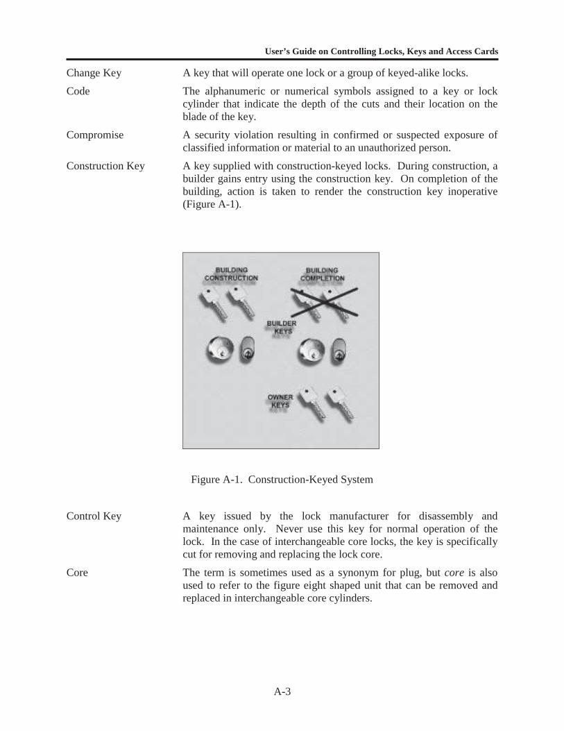
User’s Guide on Controlling Locks, Keys and Access Cards
A-3
Change Key A key that will operate one lock or a group of keyed-alike locks.
Code The alphanumeric or numerical symbols assigned to a key or lockcylinder that indicate the depth of the cuts and their location on theblade of the key.
Compromise A security violation resulting in confirmed or suspected exposure ofclassified information or material to an unauthorized person.
Construction Key A key supplied with construction-keyed locks. During construction, abuilder gains entry using the construction key. On completion of thebuilding, action is taken to render the construction key inoperative(Figure A-1).
Figure A-1. Construction-Keyed System
Control Key A key issued by the lock manufacturer for disassembly andmaintenance only. Never use this key for normal operation of thelock. In the case of interchangeable core locks, the key is specificallycut for removing and replacing the lock core.
Core The term is sometimes used as a synonym for plug, but core is alsoused to refer to the figure eight shaped unit that can be removed andreplaced in interchangeable core cylinders.
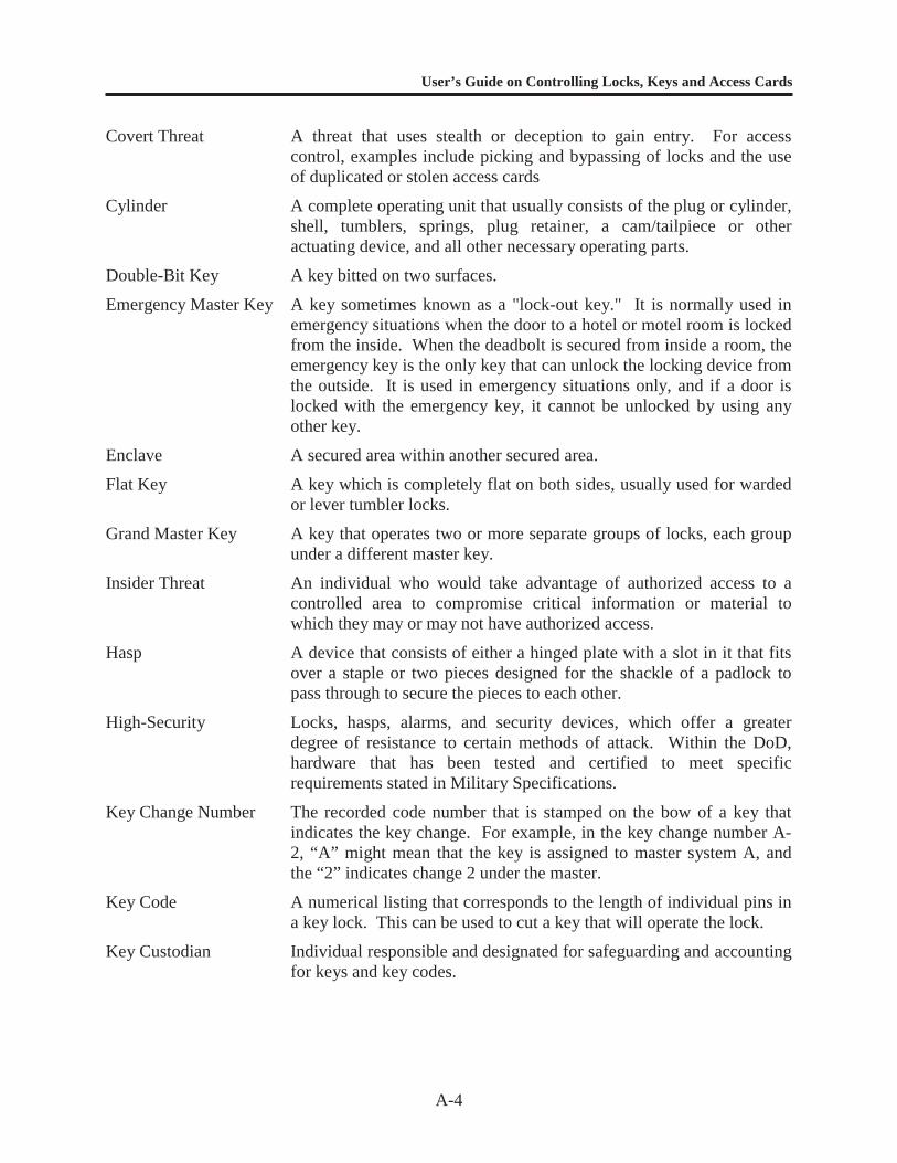
User’s Guide on Controlling Locks, Keys and Access Cards
A-4
Covert Threat A threat that uses stealth or deception to gain entry. For accesscontrol, examples include picking and bypassing of locks and the useof duplicated or stolen access cards
Cylinder A complete operating unit that usually consists of the plug or cylinder,shell, tumblers, springs, plug retainer, a cam/tailpiece or otheractuating device, and all other necessary operating parts.
Double-Bit Key A key bitted on two surfaces.
Emergency Master Key A key sometimes known as a "lock-out key." It is normally used inemergency situations when the door to a hotel or motel room is lockedfrom the inside. When the deadbolt is secured from inside a room, theemergency key is the only key that can unlock the locking device fromthe outside. It is used in emergency situations only, and if a door islocked with the emergency key, it cannot be unlocked by using anyother key.
Enclave A secured area within another secured area.
Flat Key A key which is completely flat on both sides, usually used for wardedor lever tumbler locks.
Grand Master Key A key that operates two or more separate groups of locks, each groupunder a different master key.
Insider Threat An individual who would take advantage of authorized access to acontrolled area to compromise critical information or material towhich they may or may not have authorized access.
Hasp A device that consists of either a hinged plate with a slot in it that fitsover a staple or two pieces designed for the shackle of a padlock topass through to secure the pieces to each other.
High-Security Locks, hasps, alarms, and security devices, which offer a greaterdegree of resistance to certain methods of attack. Within the DoD,hardware that has been tested and certified to meet specificrequirements stated in Military Specifications.
Key Change Number The recorded code number that is stamped on the bow of a key thatindicates the key change. For example, in the key change number A-2, “A” might mean that the key is assigned to master system A, andthe “2” indicates change 2 under the master.
Key Code A numerical listing that corresponds to the length of individual pins ina key lock. This can be used to cut a key that will operate the lock.
Key Custodian Individual responsible and designated for safeguarding and accountingfor keys and key codes.
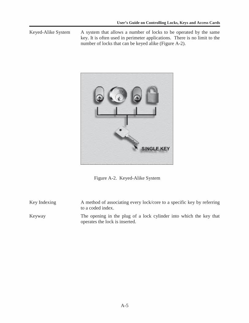
User’s Guide on Controlling Locks, Keys and Access Cards
A-5
Keyed-Alike System A system that allows a number of locks to be operated by the samekey. It is often used in perimeter applications. There is no limit to thenumber of locks that can be keyed alike (Figure A-2).
Figure A-2. Keyed-Alike System
Key Indexing A method of associating every lock/core to a specific key by referringto a coded index.
Keyway The opening in the plug of a lock cylinder into which the key thatoperates the lock is inserted.
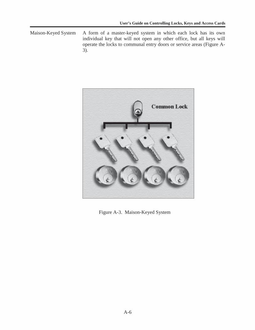
User’s Guide on Controlling Locks, Keys and Access Cards
A-6
Maison-Keyed System A form of a master-keyed system in which each lock has its ownindividual key that will not open any other office, but all keys willoperate the locks to communal entry doors or service areas (Figure A-3).
Figure A-3. Maison-Keyed System
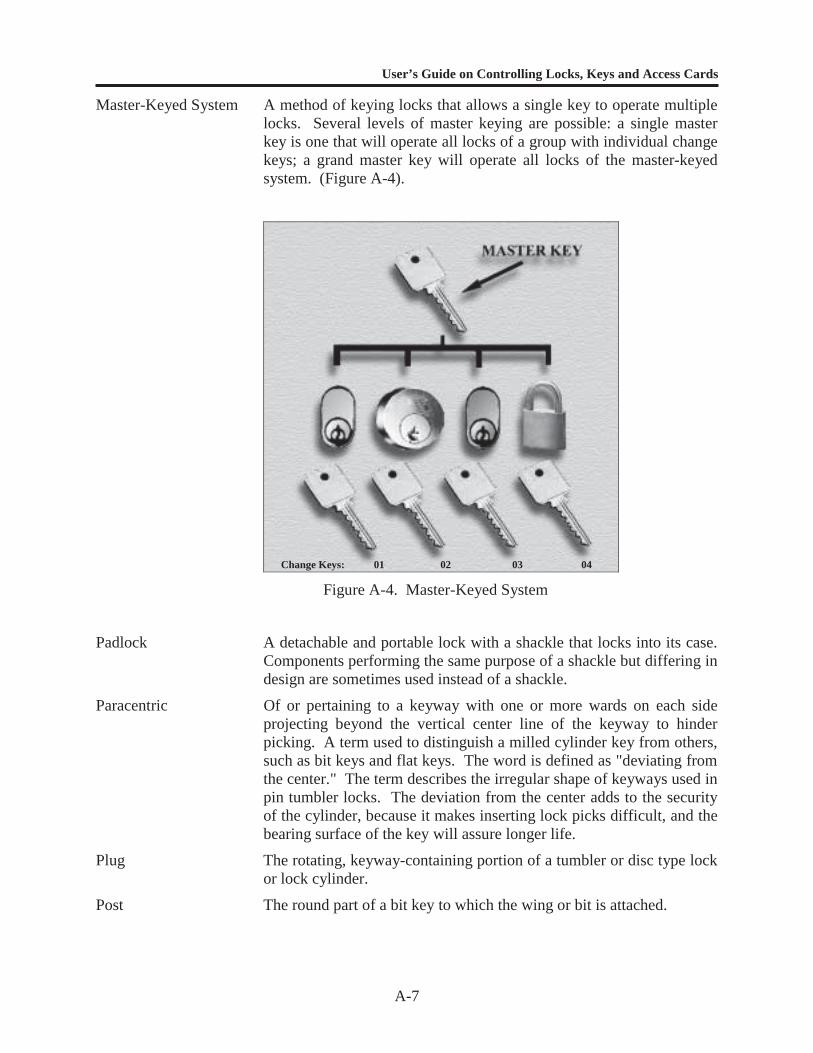
User’s Guide on Controlling Locks, Keys and Access Cards
A-7
Master-Keyed System A method of keying locks that allows a single key to operate multiplelocks. Several levels of master keying are possible: a single masterkey is one that will operate all locks of a group with individual changekeys; a grand master key will operate all locks of the master-keyedsystem. (Figure A-4).
Figure A-4. Master-Keyed System
Padlock A detachable and portable lock with a shackle that locks into its case.Components performing the same purpose of a shackle but differing indesign are sometimes used instead of a shackle.
Paracentric Of or pertaining to a keyway with one or more wards on each sideprojecting beyond the vertical center line of the keyway to hinderpicking. A term used to distinguish a milled cylinder key from others,such as bit keys and flat keys. The word is defined as "deviating fromthe center." The term describes the irregular shape of keyways used inpin tumbler locks. The deviation from the center adds to the securityof the cylinder, because it makes inserting lock picks difficult, and thebearing surface of the key will assure longer life.
Plug The rotating, keyway-containing portion of a tumbler or disc type lockor lock cylinder.
Post The round part of a bit key to which the wing or bit is attached.
Change Keys: 01 02 03 04

User’s Guide on Controlling Locks, Keys and Access Cards
A-8
Preauthorization The previously established right to enter a controlled or restricted area.
PreventiveMaintenance
Scheduled periodic inspection, cleaning, repair, and lubrication ofequipment to ensure continued performance in a workingenvironment.
Push Key A key that performs its function of aligning the tumblers with theshear line by inward rather than rotary motion.
Restricted Keyway A special keyway configuration that is not freely available and thatmust be specifically requested from the manufacturer.
Rekey Changing the core or pins in a cylinder to prevent a previously issuedkey from opening the lock.
Security Container A container usually equipped with a mounted combination lockspecifically designed for protection of classified material or sensitiveitems.
Service Life Amount of time in which the product meets or exceeds theperformance criteria for which it was designed.
Shackle The part of a padlock that passes through an opening in an object orfits around an object and is ultimately locked into the case.
Shank The part of a bit key between the bow and the stop; or, if there is noshoulder stop, the part between the bow and the near side of the bit.
Shoulder The flat portion at the end of the bow on most keys.
Stem The rounded portion at the end of a shank of a bit key to which thewing or bit is attached. The part forming the axis, on which a bit keyrotates in the lock, is also referred to as the post.
Surreptitious Entry A method of entry which would not be detectable during normal use orduring inspection by a qualified person.
Tailgating A specific method of gaining entry. Access is achieved by walking ordriving immediately behind an authorized individual or automobilewith a valid access card to gain entry before the entry point has beenallowed to close. Tailgating is also referred to as piggybacking.
Throughput Rate The maximum number of people that can enter an area in a given timeperiod.
Two-Person Rule A policy that requires two people to be present when an area or asset isaccessed.
UnderwritersLaboratories, Inc.
A national testing laboratory that tests, lists, and labels variouscategories of equipment for safety and reliability. They also publishstandards for a wide range of products, including security products.

User’s Guide on Controlling Locks and Keys and Access Cards
B-1
APPENDIX B
REFERENCES
User’s Guide on Controlling Locks and Keys and Access Cards
B-2
LIST OF REFERENCES FOR LOCK AND KEY CONTROL
1. DoD 5100.76-M, Department of Defense, “Physical Security of Conventional Arms,Ammunition and Explosives.”
2. OPNAVINST 5530.13, Department of the Navy, “Physical Security Instruction forConventional Arms, Ammunition and Explosives.”
3. OPNAVINST 5530.14, Department of the Navy, “Physical Security and Loss PreventionManual.”
4. OPNAVINST C8126.1A, Department of the Navy, “Nuclear Weapon Security Manual forCommand, Control, Communication and Intelligence,” 20 December 1994.
5. AR 190-11, Department of the Army, “Physical Security of Arms, Ammunition andExplosives.”
6. AR 190-51, Department of the Army, “Physical Security of Unclassified Army Property(Sensitive and Nonsensitive).”
7. AFI 31-209, Department of the Air Force, “Resource Protection Program.”
8. AFMAN 31-224, Department of the Air Force, “Resource Protection/Security, Facilities andEquipment.”
9. Naval Facilities Engineering Service Center, “Antipilferage Seal User’s Guide,” by theDepartment of Defense Lock Program, Port Hueneme, CA 93043, October 1997.
10. AR 190-59, Department of the Army, “Chemical Agent Security Program,” 27 June 1994.
11. DoD 5210.41M, Department of Defense, “Nuclear Weapons Security Manual (NOTAL),” 9March 1983.
12. “Master Keying by the Numbers” by Billy B. Edwards Jr., CML, Dallas, TX, RSGPublishing Corp., 1990
User’s Guide on Controlling Locks, Keys and Access Cards
C-1
APPENDIX C
SAMPLE LOCK AND KEY CONTROL PLANS

User’s Guide on Controlling Locks, Keys and Access Cards
C-2
SAMPLE LOCK AND KEY CONTROL PLAN FOR AA&E
5530(date)
(Facility) Instruction ____________________
From: Commander
Subj: LOCK AND KEY CONTROL PLAN FOR AA&E
Ref: (a) DoD 5100.76M(b) OPNAVINST 5530.13
Encl: (1) Initial Key & Lock Inventory(2) Daily Key Log(3) Monthly Key and Lock Inventory(4) (Additional forms desired by facility commander)
1. Purpose. To establish a lock and key control program for (facility) , in accordance withreferences (a) and (b).
2. Scope. Included in this plan are all keys, locks, padlocks, and locking devices used toprotect or secure restricted areas for AA&E storage facilities.
3. Definitions. (As applicable to using command. See guide definition list in Appendix A.)
4. Procedures.
a. Key Control for AA&E. A lock and key custodian will be appointed in writing and isresponsible for maintaining a key control log to ensure continuous administrativeaccountability for keys. Accountability records shall contain the signature of theindividual receiving the key, date and hour of issuance, serial number or otheridentifying information for the key, signature of the individual issuing the key, dateand hour the key was returned, and signature of the individual receiving the returnedkey. Completed key control logs shall be retained in the unit files for a minimum of90 days and then disposed of according to established procedures for destruction ofclassified information.
(1) Keys to AA&E storage buildings, rooms, racks, containers, and intrusiondetection systems shall be maintained separately from other keys and beaccessible only to those personnel whose official duties require access tothem. A current roster of personnel with authorized access shall be kept
User’s Guide on Controlling Locks, Keys and Access Cards
C-3
within the section, branch, division, or department. The roster shall beprotected from unauthorized access.
(2) When arms and ammunition are stored in the same areas, keys to thosestorage areas may be stored together, but separately from other keys. Thenumber of keys shall be held to the minimum essential. Keys may not be leftunattended or unsecured at any time. The use of a master key system isprohibited for AA&E storage.
(3) When individuals, such as duty officers, are charged with the responsibility ofsafeguarding or otherwise having keys immediately available, they shall signfor a sealed container of keys. When the sealed container of keys istransferred from one individual to another, the unbroken seal is evidence thatthe keys have not been disturbed. If the seal is found broken, an inventory ofthe container's contents will be conducted and the Security Officer will benotified immediately.
(4) Keys to AA&E storage facilities will always remain at the facility and shall bereturned immediately after the storage facility is secured.
b. Key Storage. For Category III and IV AA&E, keys will be stored in containersmade of at least 20-gauge steel, or material of equivalent strength, and equippedwith a UL 768 listed built-in, Group 1, changeable combination lock or a GSA-approved combination padlock (S&G Model 8077). Keys for Category I and IIAA&E will be stored in a Class 5 GSA-approved security container.
c. Lost, Misplaced, or Stolen Keys. In the event of lost, misplaced, or stolen keys, theaffected locks, cylinders, or cores to locks shall be replaced immediately.Replacement or reserve locks, cores, and keys shall be secured to prevent access byunauthorized individuals.
5. Locks and Seals.
a. Locking Devices. Approved locking devices are listed in Enclosure (____).
b. Rotation and Maintenance. High-security padlocks and lock cores/cylinders will berotated at least annually. This guards against the use of illegally duplicated keys andaffords the opportunity for regular maintenance to avoid lockouts or securityviolations due to malfunction caused by dirt, corrosion, and wear. Locks will bereplaced immediately if keys are lost, misplaced, stolen, or otherwise compromised.The testing, inspection, and maintenance of all high-security padlocks and keys willbe conducted annually by locksmith personnel.
(1) Maintenance, testing, and lubrication will be coordinated with normalproduction/work schedules to minimize disruption.

User’s Guide on Controlling Locks, Keys and Access Cards
C-4
(2) All maintenance, testing, and lubrication will be performed using onlyapproved procedures.
c. Padlock Security. When an AA&E storage structure is open, the padlock will belocked into the hasp or other nearby securing point to preclude the switching of thepadlock.
d. Procurement of High-Security Locks. All locks used for high-security applicationswill meet military specification MIL-P-43607. All high-security lock procurementmust be approved prior to issue.
6. Inventories.
a. AA&E Keys and Locks. Inventories of keys and locks shall be conducted semi-annually using the approved form found in enclosure (l). Inventory records shall beretained in unit files for a minimum of l year and then disposed of in accordancewith established procedures set forth in reference (e).
(signature)
Distribution:
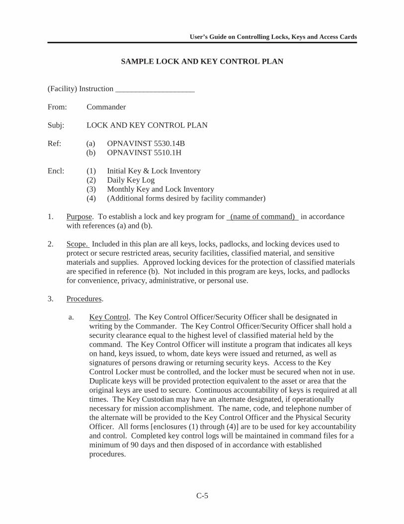
User’s Guide on Controlling Locks, Keys and Access Cards
C-5
SAMPLE LOCK AND KEY CONTROL PLAN
(Facility) Instruction ____________________
From: Commander
Subj: LOCK AND KEY CONTROL PLAN
Ref: (a) OPNAVINST 5530.14B(b) OPNAVINST 5510.1H
Encl: (1) Initial Key & Lock Inventory(2) Daily Key Log(3) Monthly Key and Lock Inventory(4) (Additional forms desired by facility commander)
1. Purpose. To establish a lock and key program for (name of command) in accordancewith references (a) and (b).
2. Scope. Included in this plan are all keys, locks, padlocks, and locking devices used toprotect or secure restricted areas, security facilities, classified material, and sensitivematerials and supplies. Approved locking devices for the protection of classified materialsare specified in reference (b). Not included in this program are keys, locks, and padlocksfor convenience, privacy, administrative, or personal use.
3. Procedures.
a. Key Control. The Key Control Officer/Security Officer shall be designated inwriting by the Commander. The Key Control Officer/Security Officer shall hold asecurity clearance equal to the highest level of classified material held by thecommand. The Key Control Officer will institute a program that indicates all keyson hand, keys issued, to whom, date keys were issued and returned, as well assignatures of persons drawing or returning security keys. Access to the KeyControl Locker must be controlled, and the locker must be secured when not in use.Duplicate keys will be provided protection equivalent to the asset or area that theoriginal keys are used to secure. Continuous accountability of keys is required at alltimes. The Key Custodian may have an alternate designated, if operationallynecessary for mission accomplishment. The name, code, and telephone number ofthe alternate will be provided to the Key Control Officer and the Physical SecurityOfficer. All forms [enclosures (1) through (4)] are to be used for key accountabilityand control. Completed key control logs will be maintained in command files for aminimum of 90 days and then disposed of in accordance with establishedprocedures.
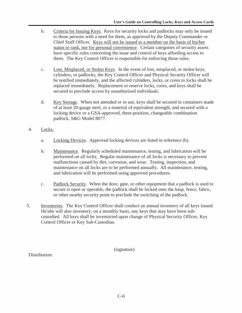
User’s Guide on Controlling Locks, Keys and Access Cards
C-6
b. Criteria for Issuing Keys. Keys for security locks and padlocks may only be issuedto those persons with a need for them, as approved by the Deputy Commander orChief Staff Officer. Keys will not be issued to a member on the basis of his/herstatus or rank, nor for personal convenience. Certain categories of security assetshave specific rules concerning the issue and control of keys affording access tothem. The Key Control Officer is responsible for enforcing those rules.
c. Lost, Misplaced, or Stolen Keys. In the event of lost, misplaced, or stolen keys,cylinders, or padlocks, the Key Control Officer and Physical Security Officer willbe notified immediately, and the affected cylinders, locks, or cores to locks shall bereplaced immediately. Replacement or reserve locks, cores, and keys shall besecured to preclude access by unauthorized individuals.
d. Key Storage. When not attended or in use, keys shall be secured in containers madeof at least 20-gauge steel, or a material of equivalent strength, and secured with alocking device or a GSA-approved, three-position, changeable combinationpadlock, S&G Model 8077.
4. Locks.
a. Locking Devices. Approved locking devices are listed in reference (b).
b. Maintenance. Regularly scheduled maintenance, testing, and lubrication will beperformed on all locks. Regular maintenance of all locks is necessary to preventmalfunctions caused by dirt, corrosion, and wear. Testing, inspection, andmaintenance on all locks are to be performed annually. All maintenance, testing,and lubrication will be performed using approved procedures.
c. Padlock Security. When the door, gate, or other equipment that a padlock is used tosecure is open or operable, the padlock shall be locked onto the hasp, fence, fabric,or other nearby security point to preclude the switching of the padlock.
5. Inventories. The Key Control Officer shall conduct an annual inventory of all keys issued.He/she will also inventory, on a monthly basis, any keys that may have been sub-custodied. All keys shall be inventoried upon change of Physical Security Officer, KeyControl Officer or Key Sub-Custodian.
(signature)Distribution:
User’s Guide on Controlling Locks, Keys and Access Cards
D-1
APPENDIX D
MECHANICAL AND ELECTRONIC ACCESS CONTROL

User’s Guide on Controlling Locks, Keys and Access Cards
D-2
INTRODUCTION
This appendix presents information on the component parts of an effective access controlsystem. For access control to work effectively, the access control system must be selected,designed, and integrated to meet the security objectives of the command. In addition, aneffective mechanical or electronic access control program must be in place so that integrity is notcompromised. Chapter 3 deals with how to establish a lock and key and/or electronic accesscard control program. The following description of measures can be applied to the design of aneffective access control system. The design and integration of access control systems is acomplex issue that is beyond the scope of this user’s guide.
DEFENSIVE MEASURES
Building layout can be used effectively to defend against covert and insider threats.Because many different situations have been anticipated in developing guidelines, apparentcontradictions may occur. Apply the guidance regarding layout where appropriate to the specificsituation.
Building Layout to Address Access Control Threats
To limit the number of visitors who must be supervised or escorted, locate facilities withlarge visitor populations separate from protected assets. Consider using on-site personnel toprovide monitoring capability or locate protected assets in common areas where the asset oraccess to the asset is visible to more than one person. This decreases the probability thatunauthorized personnel can gain undetected access to an asset. To reduce the number of accesslocations that must be monitored, minimize the number of entrances into controlled areas.Building layout considerations also include allocating adequate space for key/access controlcenters.
Because insiders generally work around the assets, simply establishing controlled areas isnot always sufficient. If all employees within a controlled area do not require access to allassets, compartmentalize the assets within the controlled area. For example, if sensitiveactivities occur in half of a building, that area should have controlled access. When only a fewpeople in the controlled area require access to a particular asset, place that asset in a room withinthe controlled area and limit access to only those with an established need.Compartmentalization, when used in conjunction with a two-person rule (no single individualcan have access to an asset without the knowledge or presence of a second person) providesadditional security protection for critical information and assets.
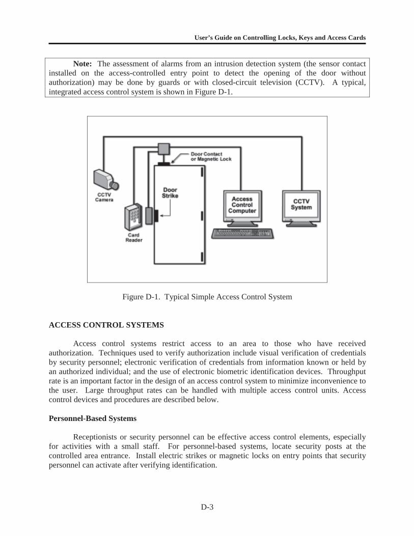
User’s Guide on Controlling Locks, Keys and Access Cards
D-3
Note: The assessment of alarms from an intrusion detection system (the sensor contactinstalled on the access-controlled entry point to detect the opening of the door withoutauthorization) may be done by guards or with closed-circuit television (CCTV). A typical,integrated access control system is shown in Figure D-1.
Figure D-1. Typical Simple Access Control System
ACCESS CONTROL SYSTEMS
Access control systems restrict access to an area to those who have receivedauthorization. Techniques used to verify authorization include visual verification of credentialsby security personnel; electronic verification of credentials from information known or held byan authorized individual; and the use of electronic biometric identification devices. Throughputrate is an important factor in the design of an access control system to minimize inconvenience tothe user. Large throughput rates can be handled with multiple access control units. Accesscontrol devices and procedures are described below.
Personnel-Based Systems
Receptionists or security personnel can be effective access control elements, especiallyfor activities with a small staff. For personnel-based systems, locate security posts at thecontrolled area entrance. Install electric strikes or magnetic locks on entry points that securitypersonnel can activate after verifying identification.

User’s Guide on Controlling Locks, Keys and Access Cards
D-4
Badging Systems. Badges are entry credentials that must include a photograph of theauthorized individual who is issued the badge. The individual keeps the badge and wears it at alltimes within the facility. Security personnel check identity by comparing the photograph on thebadge to the wearer's face. When a controlled area is compartmentalized, the badge shouldidentify specific areas of access. This is usually done through the use of code numbers orcolored stripes. Security identification badges have low to medium effectiveness as accesscontrol devices in large facilities, because badges are easily counterfeited and procedures used tochallenge access (of individuals not wearing badges or those wearing counterfeit badges) areoften ineffective. When combined with an electronic access control system however, badgesbecome an effective method for controlling access into a restricted area, because counterfeiting isminimized and bypassing an access control device is difficult without extensive knowledge ofelectronic systems and use of sophisticated card-duplicating equipment.
Visitor badges represent a significant vulnerability for badge-based access controlsystems. Visitor badges should be strictly controlled and the use of commercially available, self-expiring, and time-limited visitor badges is highly recommended. Before visitor badges areissued, authorization must be checked and identification verified by picture identification, suchas a valid driver’s license.
Badge Exchange. To provide more effective control, badge exchange can be used. Inthis method of access control, an individual receives a primary security identification badge. Asecond badge different from the first or with different access coding is kept inside the controlledarea at all times. When access is required, security personnel exchange the second badge for theindividual's primary badge. The individual wears the second badge while in the controlled area.A similar badge exchange takes place as the individual enters each compartmentalized areawithin the restricted area. When the individual leaves, the exchange process is reversed. Thisprocedure makes counterfeiting difficult, because the intruder would have to gain access to theexchange badges, as well as the primary badge.
Equipment-Based Systems
Various types of mechanical and electronic equipment can be installed to allow access tocontrolled areas not requiring the presence of security personnel. Use of keys and electronicaccess control cards, and pushbutton mechanical/electrical combination locks are sufficient forlow-level access control. Higher levels of protection require secondary credentials, such as aPIN or biometric certification, in conjunction with a card reader and keys/key cards. In addition,strict procedures or equipment must be implemented to prevent tailgating (gaining access byclosely following a person with proper credentials). When an authorized individual enters thefacility, then passes the card to an unauthorized individual for access using the same card, this iscalled “passback.” This can be controlled through the use of software designed to detectpassback conditions. The various types of equipment are described below and are presented inthe order of increasing effectiveness.
Mechanical Locks. There are two major categories of mechanical locks, as described bythe following:
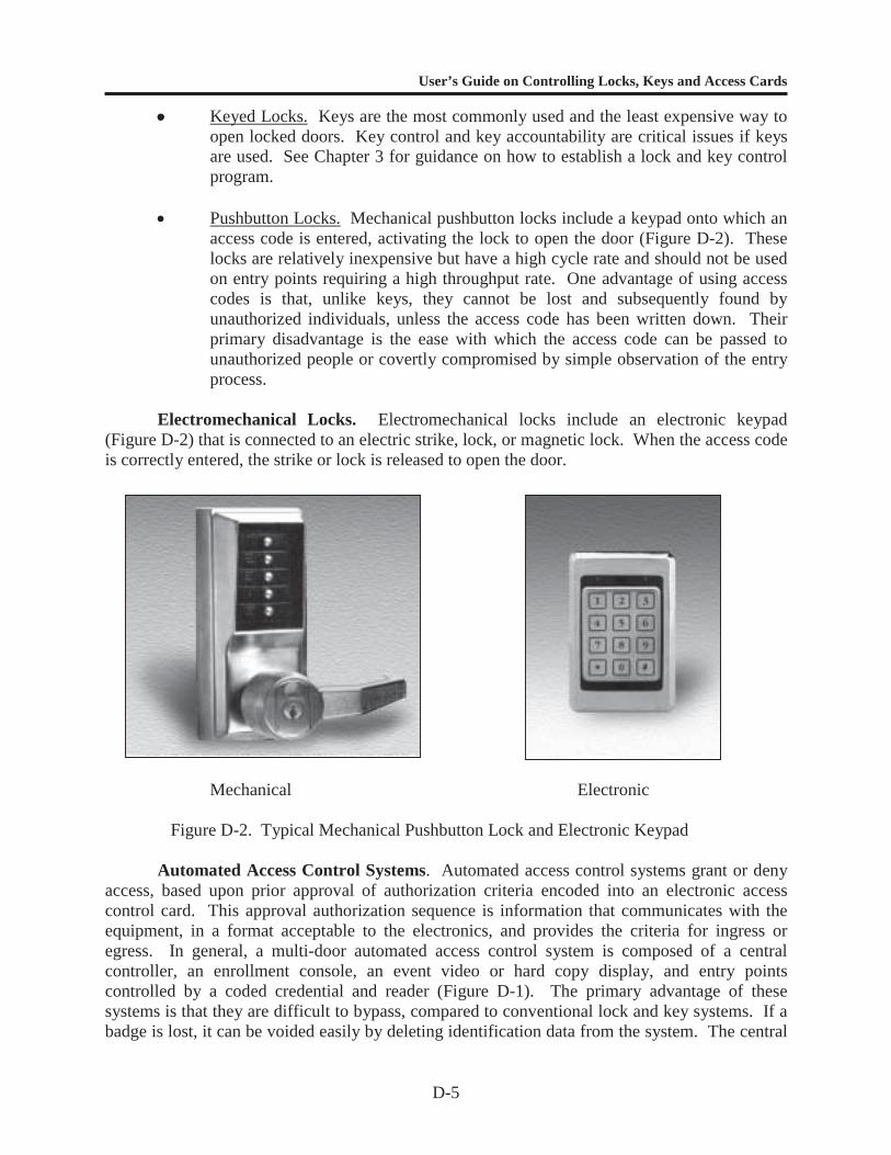
User’s Guide on Controlling Locks, Keys and Access Cards
D-5
Keyed Locks. Keys are the most commonly used and the least expensive way toopen locked doors. Key control and key accountability are critical issues if keysare used. See Chapter 3 for guidance on how to establish a lock and key controlprogram.
Pushbutton Locks. Mechanical pushbutton locks include a keypad onto which anaccess code is entered, activating the lock to open the door (Figure D-2). Theselocks are relatively inexpensive but have a high cycle rate and should not be usedon entry points requiring a high throughput rate. One advantage of using accesscodes is that, unlike keys, they cannot be lost and subsequently found byunauthorized individuals, unless the access code has been written down. Theirprimary disadvantage is the ease with which the access code can be passed tounauthorized people or covertly compromised by simple observation of the entryprocess.
Electromechanical Locks. Electromechanical locks include an electronic keypad(Figure D-2) that is connected to an electric strike, lock, or magnetic lock. When the access codeis correctly entered, the strike or lock is released to open the door.
Mechanical Electronic
Figure D-2. Typical Mechanical Pushbutton Lock and Electronic Keypad
Automated Access Control Systems. Automated access control systems grant or denyaccess, based upon prior approval of authorization criteria encoded into an electronic accesscontrol card. This approval authorization sequence is information that communicates with theequipment, in a format acceptable to the electronics, and provides the criteria for ingress oregress. In general, a multi-door automated access control system is composed of a centralcontroller, an enrollment console, an event video or hard copy display, and entry pointscontrolled by a coded credential and reader (Figure D-1). The primary advantage of thesesystems is that they are difficult to bypass, compared to conventional lock and key systems. If abadge is lost, it can be voided easily by deleting identification data from the system. The central
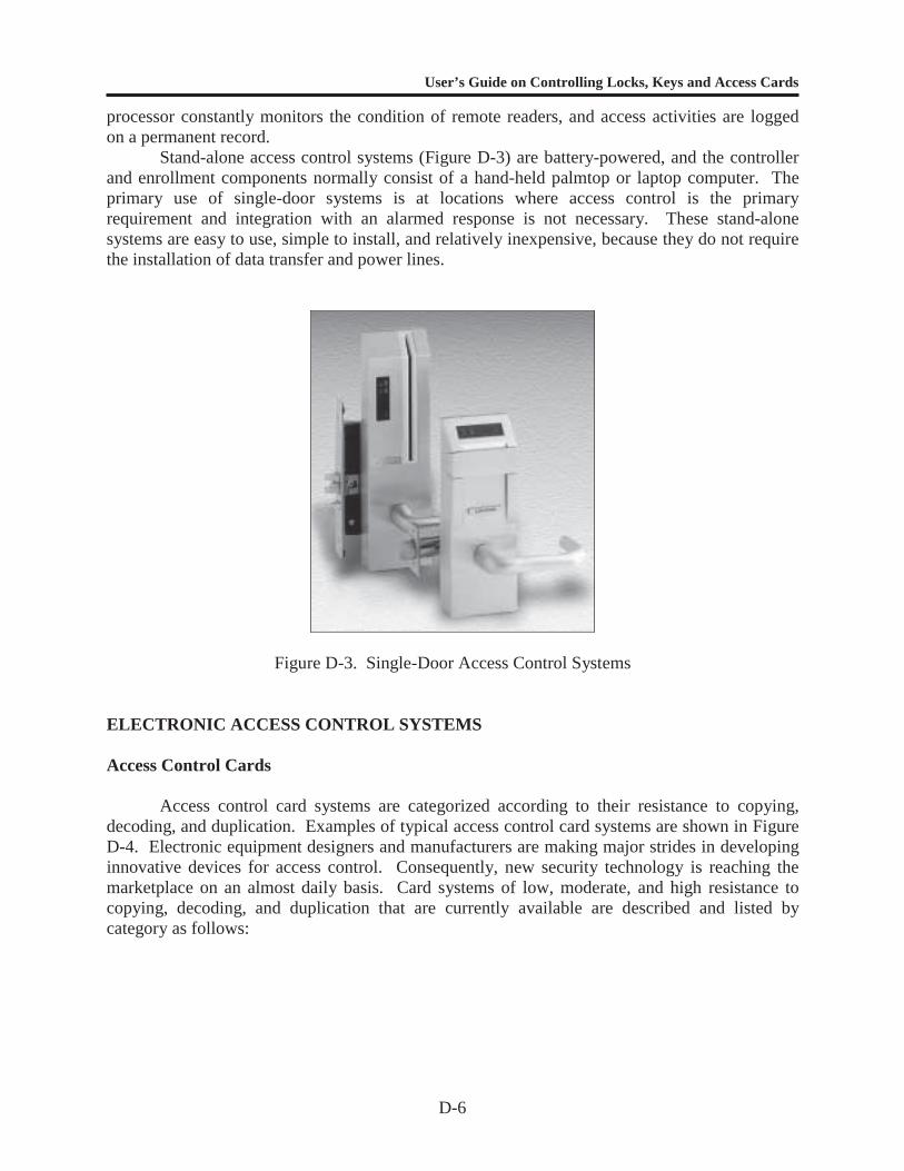
User’s Guide on Controlling Locks, Keys and Access Cards
D-6
processor constantly monitors the condition of remote readers, and access activities are loggedon a permanent record.
Stand-alone access control systems (Figure D-3) are battery-powered, and the controllerand enrollment components normally consist of a hand-held palmtop or laptop computer. Theprimary use of single-door systems is at locations where access control is the primaryrequirement and integration with an alarmed response is not necessary. These stand-alonesystems are easy to use, simple to install, and relatively inexpensive, because they do not requirethe installation of data transfer and power lines.
Figure D-3. Single-Door Access Control Systems
ELECTRONIC ACCESS CONTROL SYSTEMS
Access Control Cards
Access control card systems are categorized according to their resistance to copying,decoding, and duplication. Examples of typical access control card systems are shown in FigureD-4. Electronic equipment designers and manufacturers are making major strides in developinginnovative devices for access control. Consequently, new security technology is reaching themarketplace on an almost daily basis. Card systems of low, moderate, and high resistance tocopying, decoding, and duplication that are currently available are described and listed bycategory as follows:
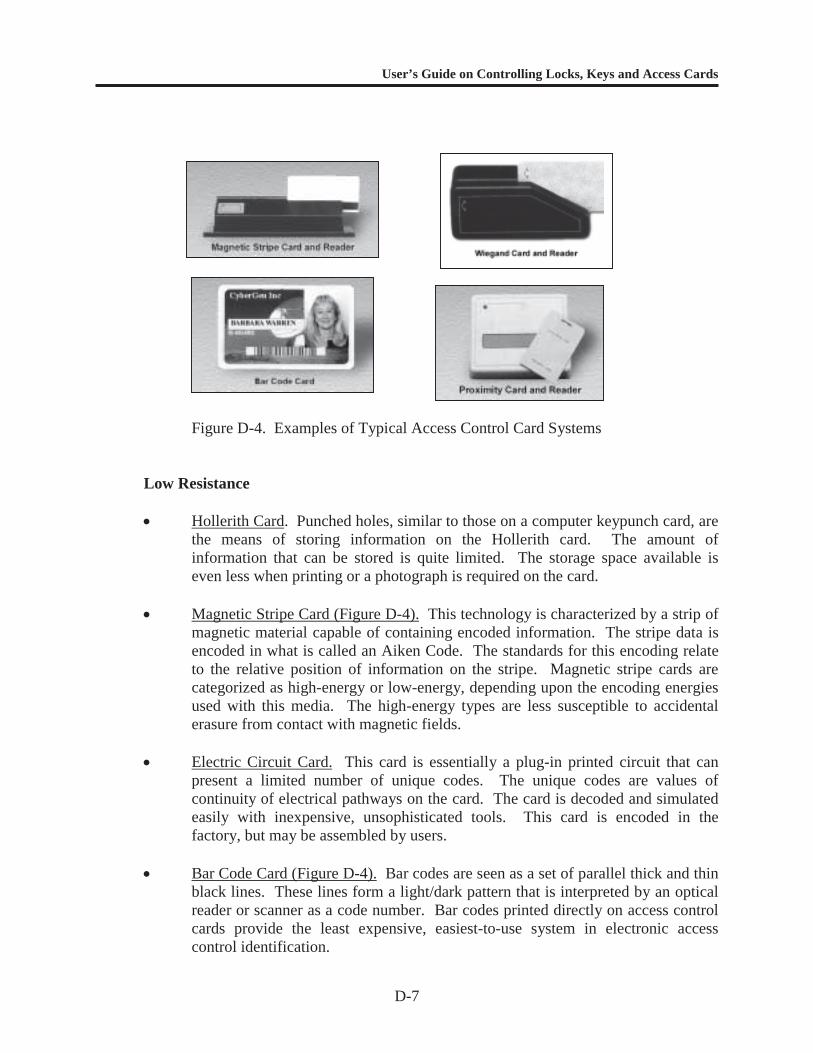
User’s Guide on Controlling Locks, Keys and Access Cards
D-7
Figure D-4. Examples of Typical Access Control Card Systems
Low Resistance
Hollerith Card. Punched holes, similar to those on a computer keypunch card, arethe means of storing information on the Hollerith card. The amount ofinformation that can be stored is quite limited. The storage space available iseven less when printing or a photograph is required on the card.
Magnetic Stripe Card (Figure D-4). This technology is characterized by a strip ofmagnetic material capable of containing encoded information. The stripe data isencoded in what is called an Aiken Code. The standards for this encoding relateto the relative position of information on the stripe. Magnetic stripe cards arecategorized as high-energy or low-energy, depending upon the encoding energiesused with this media. The high-energy types are less susceptible to accidentalerasure from contact with magnetic fields.
Electric Circuit Card. This card is essentially a plug-in printed circuit that canpresent a limited number of unique codes. The unique codes are values ofcontinuity of electrical pathways on the card. The card is decoded and simulatedeasily with inexpensive, unsophisticated tools. This card is encoded in thefactory, but may be assembled by users.
Bar Code Card (Figure D-4). Bar codes are seen as a set of parallel thick and thinblack lines. These lines form a light/dark pattern that is interpreted by an opticalreader or scanner as a code number. Bar codes printed directly on access controlcards provide the least expensive, easiest-to-use system in electronic accesscontrol identification.
User’s Guide on Controlling Locks, Keys and Access Cards
D-8
Moderate Resistance
Metallic Strip Card. This access control card consists of a matrix of metal(usually copper) strips that are laminated to a badge core. The presence orabsence of strips can encode a moderate amount of information. The card isfactory-encoded, but it may be assembled locally to add custom artwork andphotographic images.
Magnetic Spot Card. This access control card is plastic laminated andincorporates a sheet of ferromagnetic material with spots strongly andpermanently magnetized on the core material. Caution should be exercised whenplacing this card with bankcards or magnetic tape/stripe media due to the othercards’ susceptibility to erasure. The card is manufacturer encoded, but it may beassembled on-site for photograph or custom printing additions.
Optical Card. Access control cards that have rows of spots or lines that changeunder specific illumination are optically encoded. The general optically encodedcard contains spots or lines that absorb, transmit, or reflect infrared or anotherspecific light spectrum. This constitutes the unique code that is facility- and card-specific. The encoding is manufacturer-processed, because custom printing mustaccount for specific ink colors that are critical to the read technique.
High Resistance
Active Electronic Card. This miniature transmitter contains an individual codethat is sent when energized by the reader. The media is characterized by a verylimited amount of information storage.
Capacitance Card. The capacitance access control card contains an array ofcapacitor plates that are connected (or not) in a specific pattern. This pattern isthe limited information code.
Proximity Card (Figure D-4). Proximity access control cards are essentially tuned(passive) antennas, laminated within the core of a card. A weak radio signal isspectrum-generated by the card reader and is attenuated and reflected to the readeras specific information. The information on the card can be decoded.
Wiegand-Effect Card (Figure D-4). The Wiegand access control card contains aseries of small parallel wires laminated within the card. These wires aremanufactured from ferromagnetic materials that produce a sharp change inmagnetic flux when exposed to a slowly changing magnetic field. The wires'placement above and below a critical centerline determines the specificinformation in binary code. This technology is factory-encoded and, therefore,impossible to erase and difficult to alter or duplicate.

User’s Guide on Controlling Locks, Keys and Access Cards
D-9
Contact Memory Buttons (Figure D-5). A contact memory button is a computerchip armored in a stainless steel can that usually resembles a button. These chipshave up to 64K of computer memory that can store text or digitized photos. Thisinformation can be downloaded or updated as often as needed with a simple,momentary contact with the reader device. They are ideal for applications whereinformation needs to travel with a person or object. They can be used to provideaccess, carry essential information during a process, or as an electronic asset tag.Their uses are similar to that of Smart Cards, but the memory buttons arepackaged for durability, so they can be used in rugged or harsh environments.
Mixed Technology. This type of access control card combines a variety oftechnologies, including proximity, magnetic stripe, microprocessor (smart card),Wiegand, etc. Mixed technology cards can be used on a variety of readers, whicheliminates the need for carrying a number of cards at a facility with differentreader systems. They also make it unnecessary to retrofit a facility to takeadvantage of new technologies. Smart cards make biometric verification fasterand more practical by storing the information on the card, rather than in acomputer.
Figure D-5. Examples of Contact Memory Buttons
Badge Reader
Information encoded on a badge must first be decoded or read. It is then transmitted to aprocessor that grants or denies access, based upon a comparison of the encoded information withauthorization files.
A reader is composed of a card sensor and an electronic interface (Figure D-6). The cardsensor detects the presence of the coded credential and reads the data. The electronic interfaceconverts the data read by the card sensor into proper format and sends it to the controller. Thecontroller also returns a command to energize a relay that allows access.
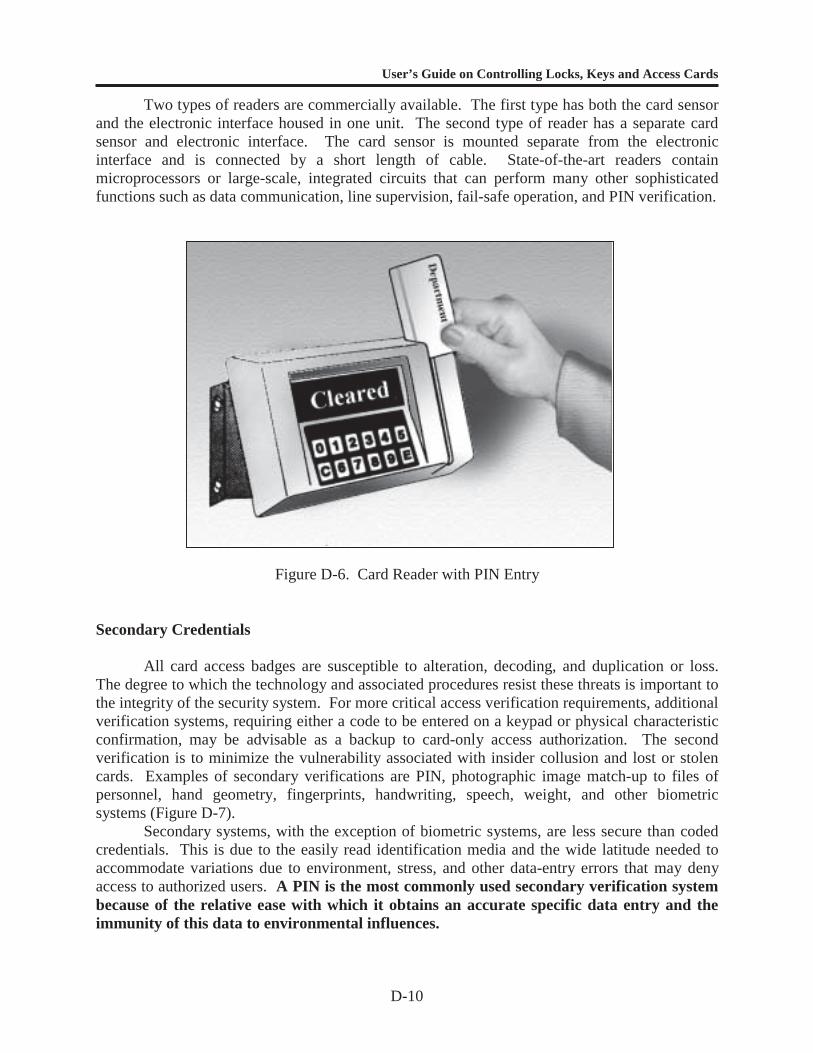
User’s Guide on Controlling Locks, Keys and Access Cards
D-10
Two types of readers are commercially available. The first type has both the card sensorand the electronic interface housed in one unit. The second type of reader has a separate cardsensor and electronic interface. The card sensor is mounted separate from the electronicinterface and is connected by a short length of cable. State-of-the-art readers containmicroprocessors or large-scale, integrated circuits that can perform many other sophisticatedfunctions such as data communication, line supervision, fail-safe operation, and PIN verification.
Figure D-6. Card Reader with PIN Entry
Secondary Credentials
All card access badges are susceptible to alteration, decoding, and duplication or loss.The degree to which the technology and associated procedures resist these threats is important tothe integrity of the security system. For more critical access verification requirements, additionalverification systems, requiring either a code to be entered on a keypad or physical characteristicconfirmation, may be advisable as a backup to card-only access authorization. The secondverification is to minimize the vulnerability associated with insider collusion and lost or stolencards. Examples of secondary verifications are PIN, photographic image match-up to files ofpersonnel, hand geometry, fingerprints, handwriting, speech, weight, and other biometricsystems (Figure D-7).
Secondary systems, with the exception of biometric systems, are less secure than codedcredentials. This is due to the easily read identification media and the wide latitude needed toaccommodate variations due to environment, stress, and other data-entry errors that may denyaccess to authorized users. A PIN is the most commonly used secondary verification systembecause of the relative ease with which it obtains an accurate specific data entry and theimmunity of this data to environmental influences.
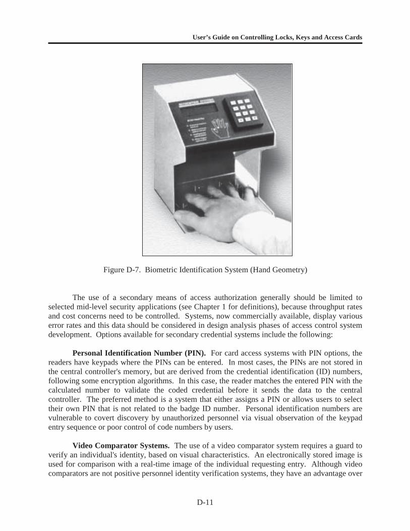
User’s Guide on Controlling Locks, Keys and Access Cards
D-11
Figure D-7. Biometric Identification System (Hand Geometry)
The use of a secondary means of access authorization generally should be limited toselected mid-level security applications (see Chapter 1 for definitions), because throughput ratesand cost concerns need to be controlled. Systems, now commercially available, display variouserror rates and this data should be considered in design analysis phases of access control systemdevelopment. Options available for secondary credential systems include the following:
Personal Identification Number (PIN). For card access systems with PIN options, thereaders have keypads where the PINs can be entered. In most cases, the PINs are not stored inthe central controller's memory, but are derived from the credential identification (ID) numbers,following some encryption algorithms. In this case, the reader matches the entered PIN with thecalculated number to validate the coded credential before it sends the data to the centralcontroller. The preferred method is a system that either assigns a PIN or allows users to selecttheir own PIN that is not related to the badge ID number. Personal identification numbers arevulnerable to covert discovery by unauthorized personnel via visual observation of the keypadentry sequence or poor control of code numbers by users.
Video Comparator Systems. The use of a video comparator system requires a guard toverify an individual's identity, based on visual characteristics. An electronically stored image isused for comparison with a real-time image of the individual requesting entry. Although videocomparators are not positive personnel identity verification systems, they have an advantage over
User’s Guide on Controlling Locks, Keys and Access Cards
D-12
manual photo ID systems in that it is difficult to tamper with the stored image used in thecomparator system. Nevertheless, they are categorized as having a low resistance tocounterfeiting. In this sense, the video comparator is comparable to the badge exchange system.Enrollment capacity is the maximum number of images that can be stored by the system. Thesystem’s access time is the time elapsed from identification number entry until the stored imageis displayed for viewing.
Hand Geometry. The measurement of relative finger length is a unique characteristic.Hand geometry is a distinct measurable and individual characteristic. These systems arecharacterized as having high to medium resistance to tampering.
Handwriting. Signature verification has been used for many years by the bankingindustry. However, signature comparison methods employed are highly susceptible to forgery.Automated handwriting verification systems have been developed that use handwritingdynamics, such as velocity, acceleration, and pressure as a function of time. Statisticalevaluation of this data indicates that an individual's signature is unique and reasonably consistentfrom one signature to the next. Systems have been developed that use from one to three axes ofdynamic measurements. Transducers can be located in either the writing instrument or tablet.Like hand geometry, signature verification has a high to medium counterfeiting resistance level.
Speech. Speech is a useful attribute for identity verification, and it is well suited toautomated data processing. Speech measurements that are useful for speaker discriminationinclude waveform envelope, voice pitch period, relative amplitude spectrum, and vocal tractresonant frequencies (formats). High-end systems have a high resistance to counterfeiting;however, some low-end systems can be fooled with high-quality recordings.
Fingerprint. Fingerprints have been used as a positive personnel identifier for more than100 years and are still considered one of the most reliable means of distinguishing one individualfrom another. The art of processing human fingerprints for identification has been greatlyenhanced in recent years by the development of automated systems. These systems, which relyon pattern recognition of either a single finger or several and computerized data processing, havean application in access control. All fingerprint identification systems require accurate fingerpositioning and pattern measurement for reliable identification. Some problems occur withindividuals that do not have clearly defined finger ridge patterns or who have had an injury to theidentifying finger. Fingerprint systems have a high resistance to counterfeiting.
Palm Print. Palm print recognition systems measure features of the palm or identify thepattern of blood vessels below the surface, or both. Palm print readers are fairly easy to use anddo not carry the emotional connotations of fingerprint ID systems. However, they are morecumbersome than fingerprint readers and some practice is required before their use becomesnatural to the user.
Eye Scan. Eye-scanning systems measure the retina or iris and are very difficult for theuser to circumvent. More advanced systems use a charge-coupled device camera, which isunobtrusive and requires little action on the user’s part. Because the scan involves shining a
User’s Guide on Controlling Locks, Keys and Access Cards
D-13
light into the retina, one potential problem with these devices is that, on a routine basis, they mayirritate the user’s eye. Employees have shown resistance to eye-scanning systems for this reason.
Electric Door Locks
Locking hardware that is compatible with automated access control systems includeselectric strikes, electric bolts, electric locksets, and electromagnetic locks. Each of these devicesis available with one of two features, termed "fail-safe" or "fail-secure," and configured in eitheralternating or direct current in a range of 6 to 240 volts. The design of an automated accesscontrol system must consider variables that are related to entry point use and the application oflocal and national fire, life safety, and electrical codes. Examples of electric door locks includethe following.
Fail-Safe/Fail-Secure. One of two operations can take place with electric door locksduring a power failure. These two operations are termed fail-safe and fail-secure. If the powerfails, the lock becomes either safe for access/egress or secure for locked. These operations areusually applied based on fire code, electrical code, or activity regulations. These codes andregulations assume that, in the event of an emergency (fire or other catastrophe), the individualseeking to exit may not be capable of rapid thought and logical reasoning and requires a simple,usually entirely mechanical, means of exit. The spirit of this requirement is to assure that speedyexit is accomplished without having to read directions or depend upon electrical orelectromechanical devices that may fail due to the emergency condition. From a securityviewpoint, this option must be clearly addressed because it can create vulnerability if proceduresare not in place to prevent reentry during alarm conditions.
Electric Strikes. The electric strike (Figure D-8) is the most commonly used electriclock. It comes in a variety of sizes and can replace existing mechanical locks without a greatdeal of difficulty. The strike, which is the electrically controlled portion of the lock mechanism,is mounted in a doorframe (jamb) and does not require wiring through the door itself. Theelectronic strike contains a bolt pocket, which is the indent that holds the protruding latch bolt ordead bolt secure in the frame. To open, the strike rotates away from the pocket, providing a pathfor the bolt to escape. This rotating side is called a pivoting lip or keeper. This device provides adepression or channel that fits the bolt or latch of the lock. The channel catches or releases thebolt, depending upon the lock status. Issues that must be considered when selecting an electricstrike include composition of the doorframe, size and shape of the latch bolt, holding force andpotential for abuse of the door lock. Heavy-duty strikes are recommendations for access controlsystems where potential abuse or high traffic volume is an issue. Options for electric strikesinclude:
1. A latch bolt monitor indicating if the bolt is extended into the strike.
2. A lock cam monitor indicating if the strike is in a locked position.
3. Sensors indicating whether the door is shut.
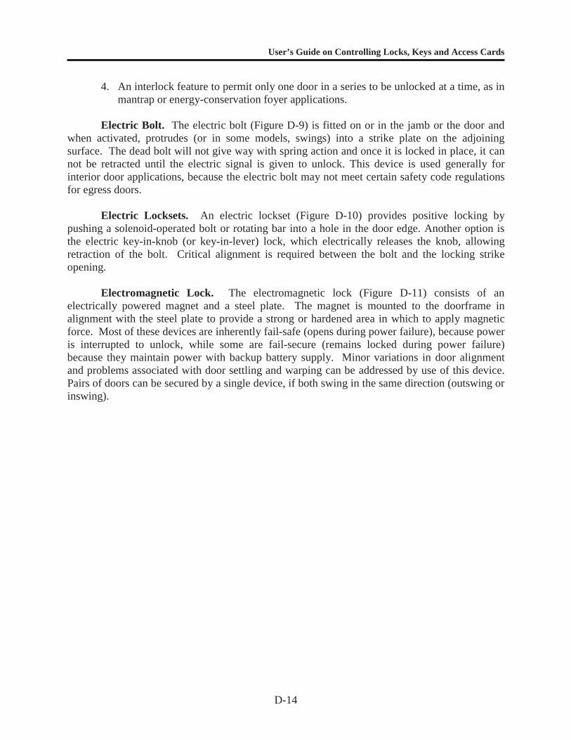
User’s Guide on Controlling Locks, Keys and Access Cards
D-14
4. An interlock feature to permit only one door in a series to be unlocked at a time, as inmantrap or energy-conservation foyer applications.
Electric Bolt. The electric bolt (Figure D-9) is fitted on or in the jamb or the door andwhen activated, protrudes (or in some models, swings) into a strike plate on the adjoiningsurface. The dead bolt will not give way with spring action and once it is locked in place, it cannot be retracted until the electric signal is given to unlock. This device is used generally forinterior door applications, because the electric bolt may not meet certain safety code regulationsfor egress doors.
Electric Locksets. An electric lockset (Figure D-10) provides positive locking bypushing a solenoid-operated bolt or rotating bar into a hole in the door edge. Another option isthe electric key-in-knob (or key-in-lever) lock, which electrically releases the knob, allowingretraction of the bolt. Critical alignment is required between the bolt and the locking strikeopening.
Electromagnetic Lock. The electromagnetic lock (Figure D-11) consists of anelectrically powered magnet and a steel plate. The magnet is mounted to the doorframe inalignment with the steel plate to provide a strong or hardened area in which to apply magneticforce. Most of these devices are inherently fail-safe (opens during power failure), because poweris interrupted to unlock, while some are fail-secure (remains locked during power failure)because they maintain power with backup battery supply. Minor variations in door alignmentand problems associated with door settling and warping can be addressed by use of this device.Pairs of doors can be secured by a single device, if both swing in the same direction (outswing orinswing).
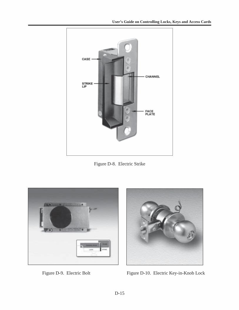
User’s Guide on Controlling Locks, Keys and Access Cards
D-15
Figure D-8. Electric Strike
Figure D-9. Electric Bolt Figure D-10. Electric Key-in-Knob Lock
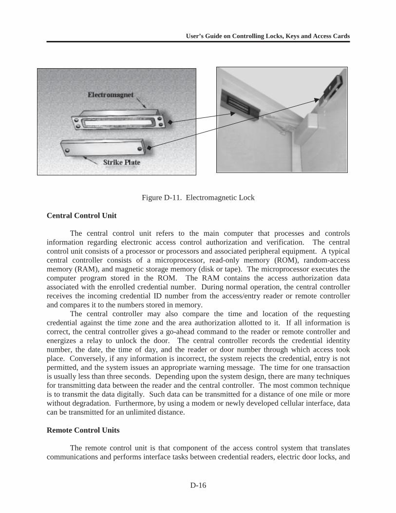
User’s Guide on Controlling Locks, Keys and Access Cards
D-16
Figure D-11. Electromagnetic Lock
Central Control Unit
The central control unit refers to the main computer that processes and controlsinformation regarding electronic access control authorization and verification. The centralcontrol unit consists of a processor or processors and associated peripheral equipment. A typicalcentral controller consists of a microprocessor, read-only memory (ROM), random-accessmemory (RAM), and magnetic storage memory (disk or tape). The microprocessor executes thecomputer program stored in the ROM. The RAM contains the access authorization dataassociated with the enrolled credential number. During normal operation, the central controllerreceives the incoming credential ID number from the access/entry reader or remote controllerand compares it to the numbers stored in memory.
The central controller may also compare the time and location of the requestingcredential against the time zone and the area authorization allotted to it. If all information iscorrect, the central controller gives a go-ahead command to the reader or remote controller andenergizes a relay to unlock the door. The central controller records the credential identitynumber, the date, the time of day, and the reader or door number through which access tookplace. Conversely, if any information is incorrect, the system rejects the credential, entry is notpermitted, and the system issues an appropriate warning message. The time for one transactionis usually less than three seconds. Depending upon the system design, there are many techniquesfor transmitting data between the reader and the central controller. The most common techniqueis to transmit the data digitally. Such data can be transmitted for a distance of one mile or morewithout degradation. Furthermore, by using a modem or newly developed cellular interface, datacan be transmitted for an unlimited distance.
Remote Control Units
The remote control unit is that component of the access control system that translatescommunications and performs interface tasks between credential readers, electric door locks, and
User’s Guide on Controlling Locks, Keys and Access Cards
D-17
the central control unit. This intermediate device is usually subject to distance constraints and isoften located to accommodate line length from readers and the central control unit. The functionof a controller includes interpretation of coded information to the central control unit. Thecontroller may also supply conditioned power to the reader.
Enrollment Console
The enrollment console is the device used to initiate the authorization status of anencoded badge. The enrollment console may contain information on badge authorization andcan include badge number, employee number, name, address, telephone number, motor vehicleregistration, status, issue date, return date, authorization center, and entry point restrictions bytime zones, entry/exit status, and trace. A commentary section may also be included foremergency call lists and other safety-related information. Enrollment equipment and equipmentused for transferring the data to the central control unit must be located in a secured area. Theenrollment console usually consists of a keyboard, badge reader, and a video display terminal.Changes of high authorization levels must be password- or software-protected to preventunauthorized use of the system. Passive software protection should be included in all systemfunctions to maintain integrity of the total system. Components of the enrollment consoleinclude a central processor and printer.
Central Processor. The central processor makes decisions based on information filesentered at the enrollment console. It also communicates with remote controllers and checks theencoded information input against the existing files. The central processor approves accessbased upon the filed authorizations and creates a historical file of attempted accesses and themanipulations of the existing files. This history may either be recorded electronically incomputer storage media or printed on paper for later review.
Other functions performed by the central processor depend upon the system design. Atone extreme, only minimal capability is assigned at the entry point and reader. Consequently,data is transmitted to the central control unit, and the central processor makes decisions. At theother extreme, significant capability is assigned at the entry point and reader, and decisions aremade locally, which allows faster processing and entry. In all cases, reader status and alarmstatus signals are sent to the central processor, then transferred to the information display in theguard station.
Printer. The printer is an output device that provides a hard-copy record of activitiesreported by the central processor. Printers should have sufficient speed and appropriate buffer toavoid information omissions from overload by the much faster system electronics. Securitysystems do not generally require letter quality printing, so faster printing can be selected for thisoperation.
Accessories
To extend or enhance the capabilities of a system, accessories may be added to the basicsystem. Three types of useful accessories are multiplexers, alarm-switch monitors, and computerinterface modules.
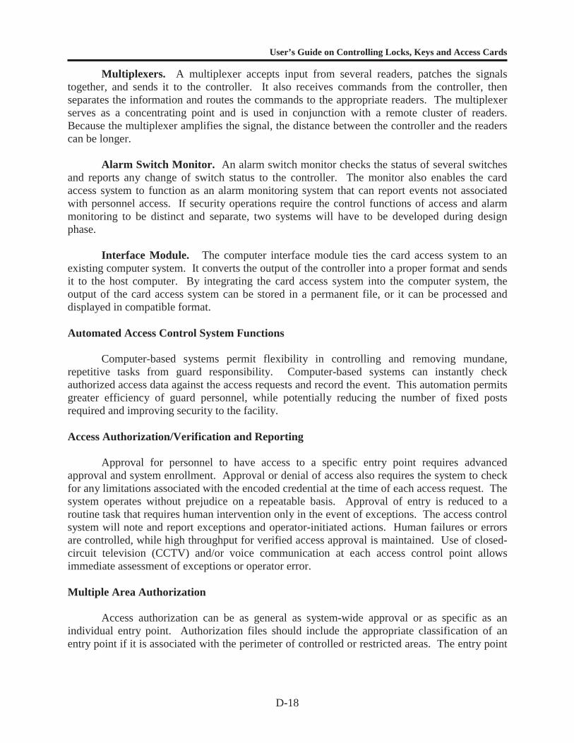
User’s Guide on Controlling Locks, Keys and Access Cards
D-18
Multiplexers. A multiplexer accepts input from several readers, patches the signalstogether, and sends it to the controller. It also receives commands from the controller, thenseparates the information and routes the commands to the appropriate readers. The multiplexerserves as a concentrating point and is used in conjunction with a remote cluster of readers.Because the multiplexer amplifies the signal, the distance between the controller and the readerscan be longer.
Alarm Switch Monitor. An alarm switch monitor checks the status of several switchesand reports any change of switch status to the controller. The monitor also enables the cardaccess system to function as an alarm monitoring system that can report events not associatedwith personnel access. If security operations require the control functions of access and alarmmonitoring to be distinct and separate, two systems will have to be developed during designphase.
Interface Module. The computer interface module ties the card access system to anexisting computer system. It converts the output of the controller into a proper format and sendsit to the host computer. By integrating the card access system into the computer system, theoutput of the card access system can be stored in a permanent file, or it can be processed anddisplayed in compatible format.
Automated Access Control System Functions
Computer-based systems permit flexibility in controlling and removing mundane,repetitive tasks from guard responsibility. Computer-based systems can instantly checkauthorized access data against the access requests and record the event. This automation permitsgreater efficiency of guard personnel, while potentially reducing the number of fixed postsrequired and improving security to the facility.
Access Authorization/Verification and Reporting
Approval for personnel to have access to a specific entry point requires advancedapproval and system enrollment. Approval or denial of access also requires the system to checkfor any limitations associated with the encoded credential at the time of each access request. Thesystem operates without prejudice on a repeatable basis. Approval of entry is reduced to aroutine task that requires human intervention only in the event of exceptions. The access controlsystem will note and report exceptions and operator-initiated actions. Human failures or errorsare controlled, while high throughput for verified access approval is maintained. Use of closed-circuit television (CCTV) and/or voice communication at each access control point allowsimmediate assessment of exceptions or operator error.
Multiple Area Authorization
Access authorization can be as general as system-wide approval or as specific as anindividual entry point. Authorization files should include the appropriate classification of anentry point if it is associated with the perimeter of controlled or restricted areas. The entry point
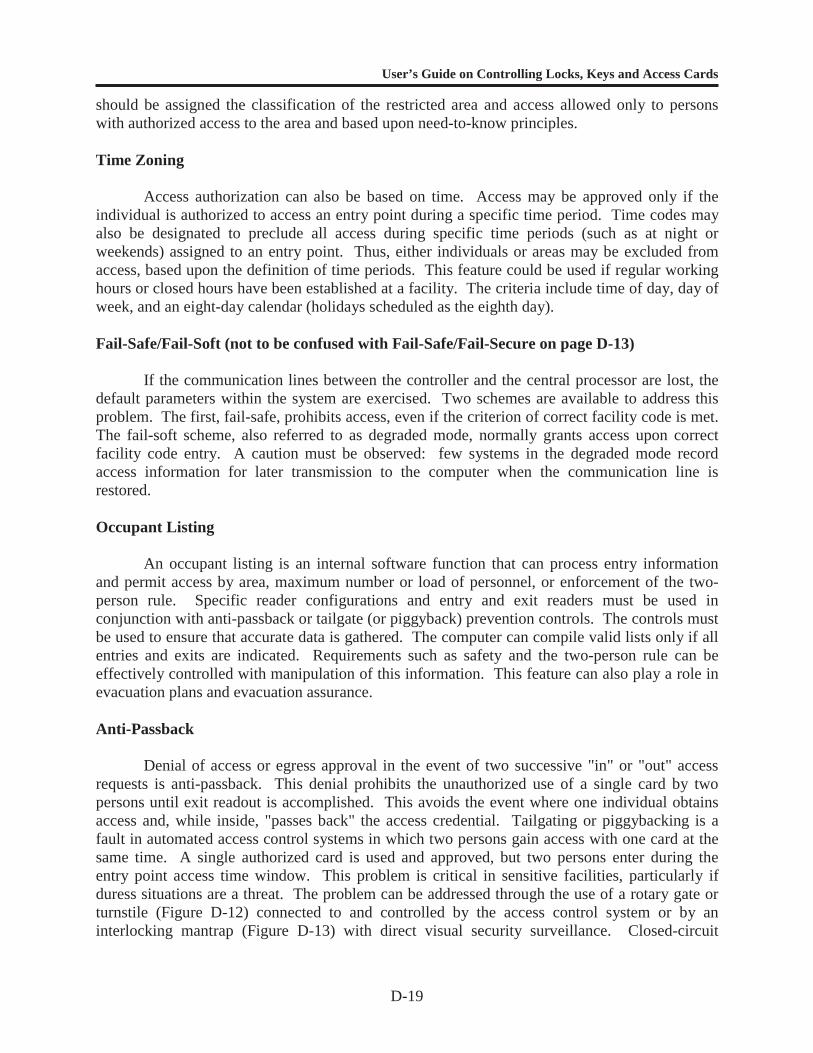
User’s Guide on Controlling Locks, Keys and Access Cards
D-19
should be assigned the classification of the restricted area and access allowed only to personswith authorized access to the area and based upon need-to-know principles.
Time Zoning
Access authorization can also be based on time. Access may be approved only if theindividual is authorized to access an entry point during a specific time period. Time codes mayalso be designated to preclude all access during specific time periods (such as at night orweekends) assigned to an entry point. Thus, either individuals or areas may be excluded fromaccess, based upon the definition of time periods. This feature could be used if regular workinghours or closed hours have been established at a facility. The criteria include time of day, day ofweek, and an eight-day calendar (holidays scheduled as the eighth day).
Fail-Safe/Fail-Soft (not to be confused with Fail-Safe/Fail-Secure on page D-13)
If the communication lines between the controller and the central processor are lost, thedefault parameters within the system are exercised. Two schemes are available to address thisproblem. The first, fail-safe, prohibits access, even if the criterion of correct facility code is met.The fail-soft scheme, also referred to as degraded mode, normally grants access upon correctfacility code entry. A caution must be observed: few systems in the degraded mode recordaccess information for later transmission to the computer when the communication line isrestored.
Occupant Listing
An occupant listing is an internal software function that can process entry informationand permit access by area, maximum number or load of personnel, or enforcement of the two-person rule. Specific reader configurations and entry and exit readers must be used inconjunction with anti-passback or tailgate (or piggyback) prevention controls. The controls mustbe used to ensure that accurate data is gathered. The computer can compile valid lists only if allentries and exits are indicated. Requirements such as safety and the two-person rule can beeffectively controlled with manipulation of this information. This feature can also play a role inevacuation plans and evacuation assurance.
Anti-Passback
Denial of access or egress approval in the event of two successive "in" or "out" accessrequests is anti-passback. This denial prohibits the unauthorized use of a single card by twopersons until exit readout is accomplished. This avoids the event where one individual obtainsaccess and, while inside, "passes back" the access credential. Tailgating or piggybacking is afault in automated access control systems in which two persons gain access with one card at thesame time. A single authorized card is used and approved, but two persons enter during theentry point access time window. This problem is critical in sensitive facilities, particularly ifduress situations are a threat. The problem can be addressed through the use of a rotary gate orturnstile (Figure D-12) connected to and controlled by the access control system or by aninterlocking mantrap (Figure D-13) with direct visual security surveillance. Closed-circuit
User’s Guide on Controlling Locks, Keys and Access Cards
D-20
television assessment, in addition to access control at entry points, the less effective “beambreak,” and personnel counting devices with appropriate alarm/delay features, should also beused for these applications.
Figure D-12. Turnstile
Figure D-13. Mantrap
User’s Guide on Controlling Locks, Keys and Access Cards
D-21
General Automated Access Control Applications
Several factors directly affect the successful operation of an electronic access controlsystem. System designers must be familiar with limitations and constraints.
The selection of an access control system involves virtually as many factors as there arepotential applications. Because selection will generally be commercial, off-the-shelf systems,the two primary considerations are first, the capabilities of the proposed equipment, in terms oflocal security/use requirements, and second the experience and capabilities of the installationfirm to support the equipment during its life cycle. These two factors need to be consideredtogether, because poor installation and service can negate the benefits of the most detailed designprocess. Maintenance must be examined as part of the life cycle cost of the system.
The standard features of the automated access control system enhance securityoperations, particularly where the equipment outperforms humans in repetitive functions. Thiscreates a more secure environment, because it allows the human element to perform in the areawhere greater efficiencies can be achieved. Definition of access, based upon area, access point,time zone, holiday schedule, loading, two-person rule, and the subsequent recording of theinformation relative to use, can be essential. Automation of electronic alarm processing withinone control center provides a single source of information regarding the facility or activitysecurity. Other software enhancements, such as automated guard tours and patrols, redundantlife safety system monitoring, security trace, data encryption, and centralized control/reporting,can improve the versatility of the system. The capability of the system to call up electroniccommands to address detected events with specific details, telephone numbers, and prioritizedsequences further reduces the margin for error by reducing the requirements for humanjudgment.
Design of the access control system should take into consideration an expansioncapability of at least 25 percent with minimum hardware and software additions. The bestsystems permit additions of equipment to meet expansion, without obsolescence of existinghardware. Modular enhancements in hardware capability permit maximum configuration untilthe central processor is outgrown and additional or different processors are required. State-of-the-art processing equipment is designed to be implemented in building blocks, with logicalbreaks, in order to meet individualized usage. Off-the-shelf modules that are systemenhancement-oriented often provide the required capabilities cost effectively.
The degree of access level designed into a system is based upon the protected areasecurity requirement, authorized need for access through a particular entry point, and therequired resistance to defeating the identity verifier. The throughput rate is the average numberof individuals who can pass through an entry point during a specific period of time. Normally,the throughput rate is specified in personnel per minute. The design at the requirements phaseshould identify all entry points scheduled for control and determine the number of authorizedpersonnel who use each entry/egress control point. The configuration of each control point willbe expanded based upon peak throughput requirements, primarily at shift changes. Theemployment of positive barriers, such as sallyports, turnstiles, or other access limitations, willdetermine the number of readers required to conveniently process legitimate access. Cardcredentials alone typically will require 3 to 5 seconds per card when configured properly.
In normal operation, automated access control systems provide a given level of securityby restricting unauthorized access. Although this level of security may normally be sufficient,

User’s Guide on Controlling Locks, Keys and Access Cards
D-22
equipment failure can decrease security to an unacceptable level. Failure of critical equipmentmay cause total system failure. Efforts must be made to minimize both the impact of systemfailure and the associated repair time.
User’s Guide on Controlling Locks, Keys and Access Cards
APPENDIX E
LOCK AND KEY CONTROL FORMS
E-1
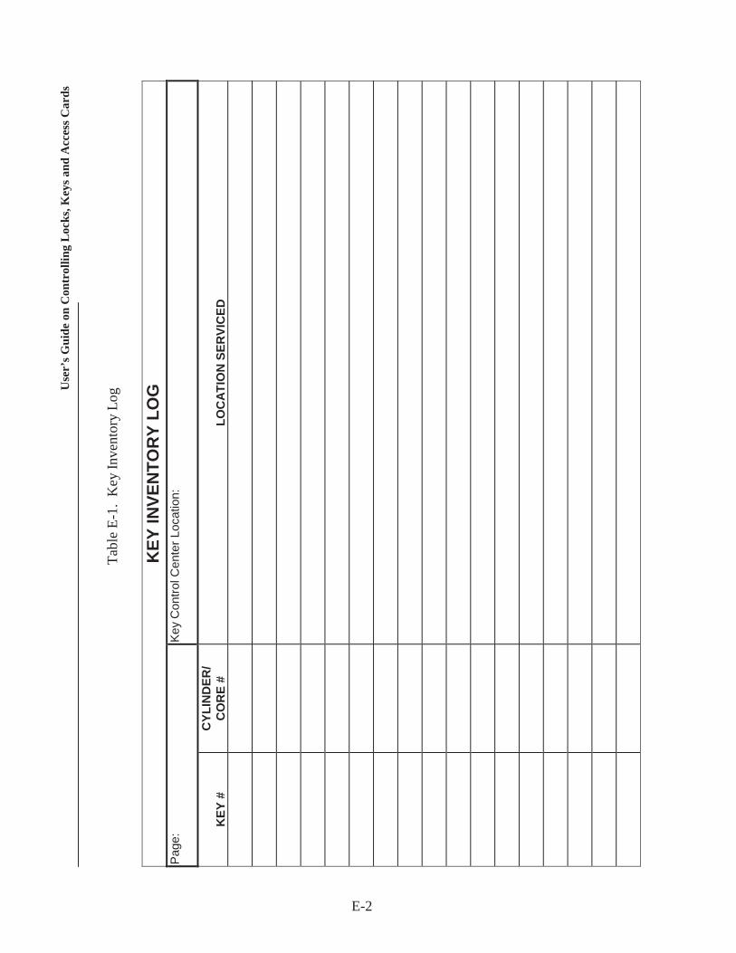
Use
r’s G
uide
on
Con
trol
ling
Loc
ks, K
eys a
nd A
cces
s Car
ds
Tabl
e E-
1. K
ey In
vent
ory
Log
KEY
INVE
NTO
RY
LOG
Page
:Ke
y C
ontro
l Cen
ter L
ocat
ion:
KEY
#C
YLIN
DER
/C
OR
E #
LOC
ATIO
N S
ERVI
CED
E-2
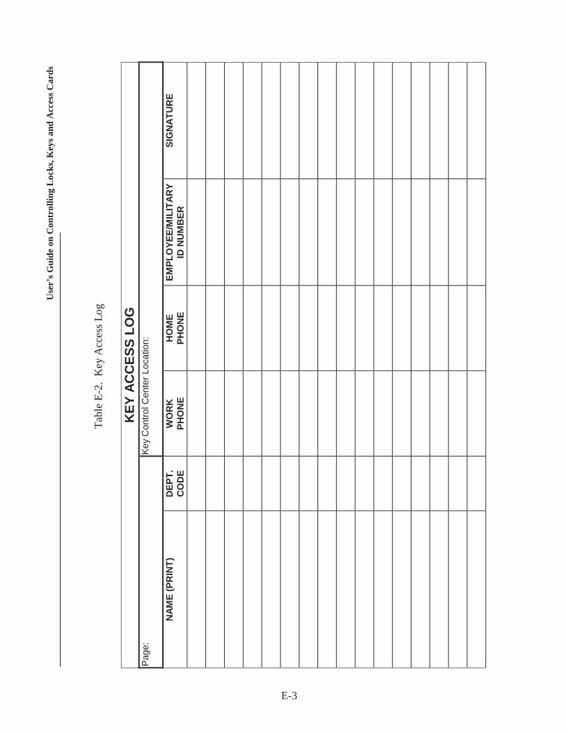
Use
r’s G
uide
on
Con
trol
ling
Loc
ks, K
eys a
nd A
cces
s Car
ds
Tabl
e E-
2. K
ey A
cces
s Log
KEY
AC
CES
S LO
GPa
ge:
Key
Con
trol C
ente
r Loc
atio
n:
NAM
E (P
RIN
T)D
EPT.
CO
DE
WO
RK
PHO
NE
HO
ME
PHO
NE
EMPL
OYE
E/M
ILIT
ARY
ID N
UM
BER
SIG
NAT
UR
E
E-3
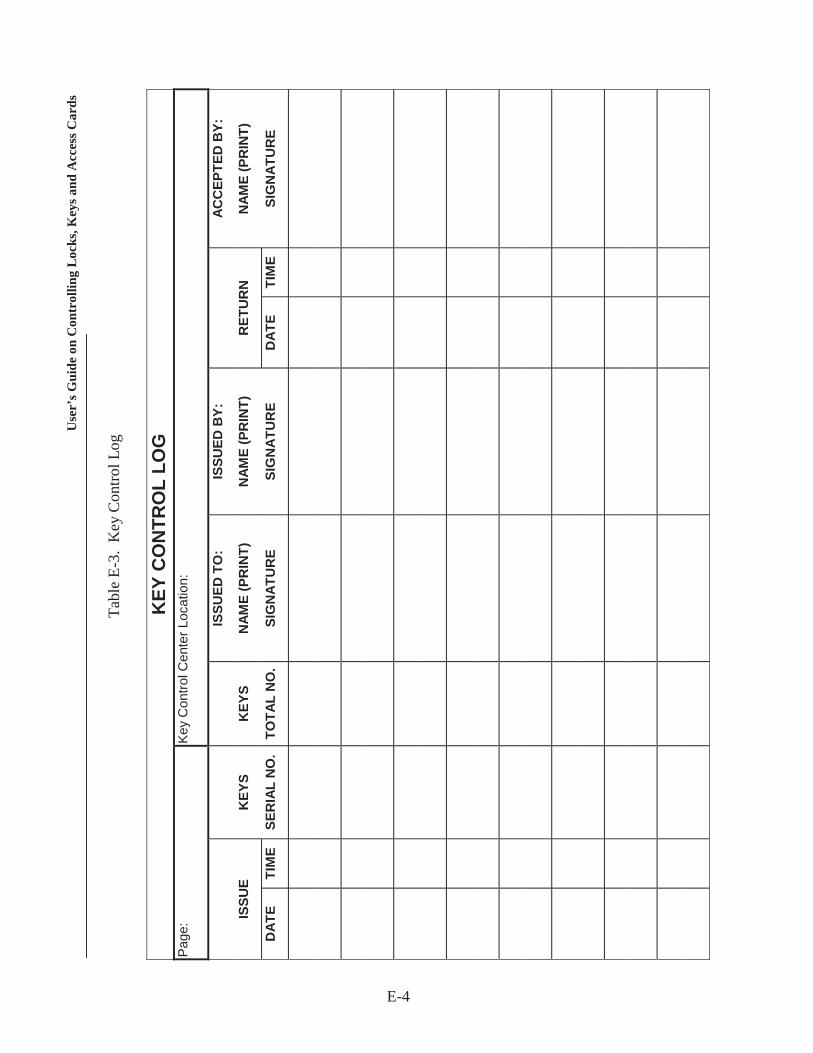
Use
r’s G
uide
on
Con
trol
ling
Loc
ks, K
eys a
nd A
cces
s Car
ds
Tabl
e E-
3. K
ey C
ontro
l Log
KEY
CO
NTR
OL
LOG
Page
:Ke
y C
ontro
l Cen
ter L
ocat
ion:
ISSU
ED T
O:
ISSU
ED B
Y:AC
CEP
TED
BY:
ISSU
EK
EYS
KEY
SN
AME
(PR
INT)
NAM
E (P
RIN
T)R
ETU
RN
NAM
E (P
RIN
T)
DAT
ETI
ME
SER
IAL
NO
.TO
TAL
NO
.SI
GN
ATU
RE
SIG
NAT
UR
ED
ATE
TIM
ESI
GN
ATU
RE
E-4
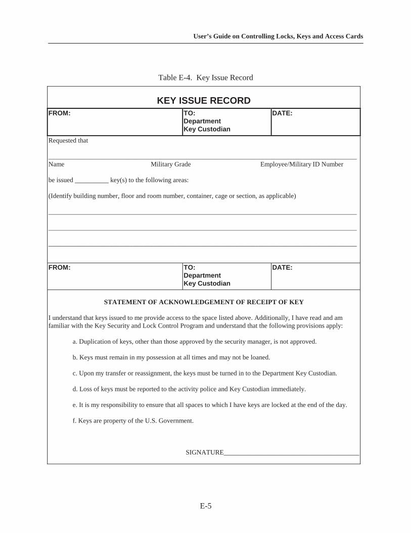
User’s Guide on Controlling Locks, Keys and Access Cards
E-5
Table E-4. Key Issue Record
KEY ISSUE RECORDFROM: TO:
DepartmentKey Custodian
DATE:
Requested that
___________________________________________________________________________________________Name Military Grade Employee/Military ID Number
be issued __________ key(s) to the following areas:
(Identify building number, floor and room number, container, cage or section, as applicable)
___________________________________________________________________________________________
___________________________________________________________________________________________
___________________________________________________________________________________________
FROM: TO:DepartmentKey Custodian
DATE:
STATEMENT OF ACKNOWLEDGEMENT OF RECEIPT OF KEY
I understand that keys issued to me provide access to the space listed above. Additionally, I have read and amfamiliar with the Key Security and Lock Control Program and understand that the following provisions apply:
a. Duplication of keys, other than those approved by the security manager, is not approved.
b. Keys must remain in my possession at all times and may not be loaned.
c. Upon my transfer or reassignment, the keys must be turned in to the Department Key Custodian.
d. Loss of keys must be reported to the activity police and Key Custodian immediately.
e. It is my responsibility to ensure that all spaces to which I have keys are locked at the end of the day.
f. Keys are property of the U.S. Government.
SIGNATURE________________________________________
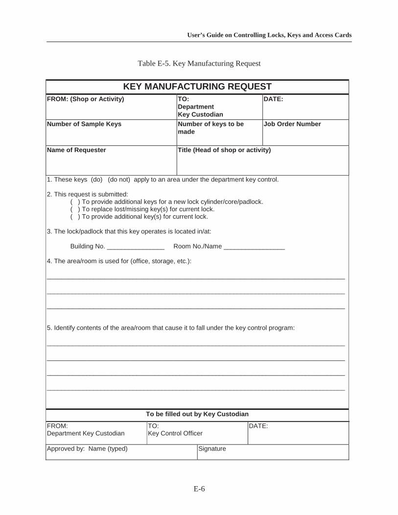
User’s Guide on Controlling Locks, Keys and Access Cards
E-6
Table E-5. Key Manufacturing Request
KEY MANUFACTURING REQUESTFROM: (Shop or Activity) TO:
DepartmentKey Custodian
DATE:
Number of Sample Keys Number of keys to bemade
Job Order Number
Name of Requester Title (Head of shop or activity)
1. These keys (do) (do not) apply to an area under the department key control.
2. This request is submitted:( ) To provide additional keys for a new lock cylinder/core/padlock.( ) To replace lost/missing key(s) for current lock.( ) To provide additional key(s) for current lock.
3. The lock/padlock that this key operates is located in/at:
Building No. ________________ Room No./Name _________________
4. The area/room is used for (office, storage, etc.):
___________________________________________________________________________________
___________________________________________________________________________________
___________________________________________________________________________________
5. Identify contents of the area/room that cause it to fall under the key control program:
___________________________________________________________________________________
___________________________________________________________________________________
___________________________________________________________________________________
___________________________________________________________________________________
To be filled out by Key Custodian
FROM:Department Key Custodian
TO:Key Control Officer
DATE:
Approved by: Name (typed) Signature
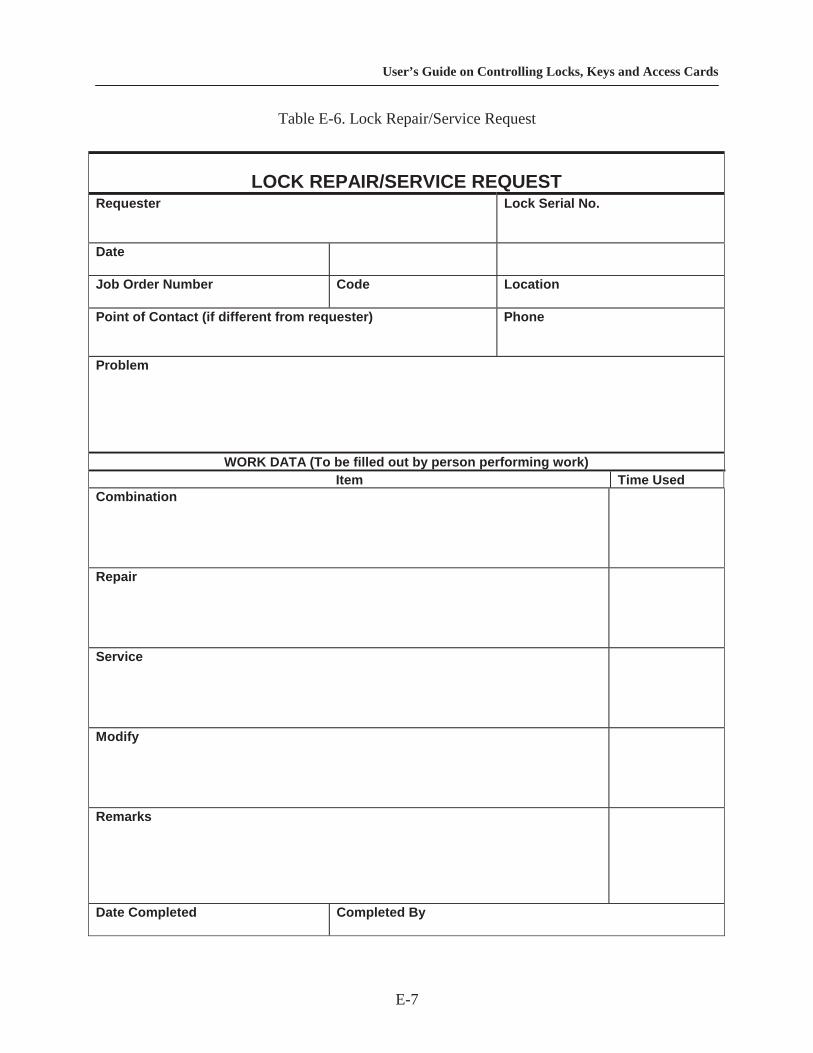
User’s Guide on Controlling Locks, Keys and Access Cards
E-7
Table E-6. Lock Repair/Service Request
LOCK REPAIR/SERVICE REQUESTRequester Lock Serial No.
Date
Job Order Number Code Location
Point of Contact (if different from requester) Phone
Problem
WORK DATA (To be filled out by person performing work)Item Time Used
Combination
Repair
Service
Modify
Remarks
Date Completed Completed By

User’s Guide o n Controlling Locks, Keys and Access Cards
F-1
APPENDIX F
MANUFACTURERS LISTING
NOTE: This is only a partial list. Any reference to a manufacturer is included only toillustrate a piece of equipment. It is not intended to be a recommendation or an endorsementof any product or company.

User’s Guide o n Controlling Locks, Keys and Access Cards
F-2
ALPHABETICAL LISTING OF MANUFACTURERS
MANUFACTURER/ADDRESS/PHONE PRODUCTSAbloy Security, Inc., 6015 Commerce Drive, Suite 450, IrvingTX 75063 (214) 753-1127, (800) 367-4598
Locks and key controlequipment
ADT Security Services, Inc., 1400 East Exposition Avenue,Aurora, CO 80012-2512, (303) 338-8200, (800) 662-5378
Electronic security products andservices
AES Corporation, 285 Newbury Street, P.O. Box 2093,Peabody, MA 01960, (506) 535-7310, (800) 237-6387
Central alarm reporting systems
Allsafe Company, Inc., 1105 Broadway, Buffalo, NY 14212,(716) 896-4515, (800) 828-7162
Access control cards andsystems
American Lock Co., 3400 W. Exchange Road, Crete, IL60417, (708) 534-2000, (800) 323-4568
Padlocks, hasps, and cam locks
Apollo, 3610 Birch Street, Newport Beach, CA 92660, (714) 852-8178
Access control products, alarmpanels, readers, software, andbadging systems
Applied Real-time Systems, Inc., 1700 Highway 59,Mandeville, LA 70448, (504) 626-1111, (800) 256-2003
Hardware and software foraccess control
Arrow Lock, 103-00 Forster Avenue, Brooklyn, NY 11236,(718) 257-4700
Locks, key control software,interchangeable core products
ASSA High Security Locks, 10300 Foster Avenue, Brooklyn,NY 11236, (718) 927-2772, (800) 221-6529
Mechanical locks and key-making equipment
Best Access Systems, 6161 East 75th Street, P.O. Box 50444,Indianapolis, IN 46250 (317) 849-2250
Locks, access controlequipment, key control andmanagement software
Cardkey Systems, Inc., 1757 Tapo Canyon Road, SimiValley, CA 93063, (805) 522-5555
Card-reader systems, computer-based access control systems
Casi-Rusco, 1155 Broken Sound Parkway NW, Boca Raton,FL 33487, (561) 998-6100
Integrated access controlsystems
Chubb Lock and Safe, 42 Shaft Road, Rexdale, ON M9W4M2 Canada, (416) 249-7241
Locks, door hardware, accesscontrol systems, electric locks,vaults, and safes
Continental Instruments Corp., 70 Hopper Street, Westbury,NY 11590, (516) 334-0900
Card-reader systems, computer-based access control systems,electronic door locks
Control Systems International, Inc., 1625 West Crosby Road,Carrollton, TX 75007, (972) 323-1111, (800) 274-5551
Access control systems
Controlled Access, Inc., 1256 North Church Street, Suite D,Moorestown, NJ 08057, (609) 866-5525, (800) 377-5050
Computer-based access controlsystems
CorKey Control Systems, Inc., 3427 Enterprise, Hayward, CA94545-3201, (510) 786-4241, (800) 622-2239
Magnetic locking hardware
Dayton Safe Company, 30 Kiser Street, Dayton, OH 45404,(937) 461-3900
Safes, lockers, and safetydeposit boxes
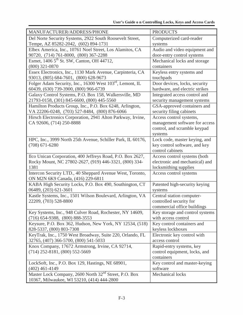
User’s Guide o n Controlling Locks, Keys and Access Cards
F-3
MANUFACTURER/ADDRESS/PHONE PRODUCTSDel Norte Security Systems, 2922 South Roosevelt Street,Tempe, AZ 85282-2042, (602) 894-1731
Computerized card-readersystems
Elbex America, Inc., 10761 Noel Street, Los Alamitos, CA90720, (714) 761-8000, (800) 367-2288
Audio and video equipment anddoor-entry control systems
Esmet, 1406 5th St. SW, Canton, OH 44712,(800) 321-0870
Mechanical locks and storagecontainers
Essex Electronics, Inc., 1130 Mark Avenue, Carpinteria, CA93013, (805) 684-7601, (800) 628-9673
Keyless entry systems andtouchpads
Folger Adam Security, Inc., 16300 West 103rd, Lemont, IL60439, (630) 739-3900, (800) 966-6739
Door devices, locks, securityhardware, and electric strikes
Galaxy Control Systems, P.O. Box 158, Walkersville, MD21793-0158, (301) 845-6600, (800) 445-5560
Integrated access control andsecurity management systems
Hamilton Products Group, Inc., P.O. Box 6248, Arlington,VA 22206-0248, (703) 527-8484, (800) 876-6066
GSA-approved containers andsecurity filing cabinets
Hirsch Electronics Corporation, 2941 Alton Parkway, Irvine,CA 92606, (714) 250-8888
Access control systems,management software for accesscontrol, and scramble keypadsystems
HPC, Inc., 3999 North 25th Avenue, Schiller Park, IL 60176,(708) 671-6280
Lock code, master keying, andkey control software, and keycontrol cabinets
Ilco Unican Corporation, 400 Jeffreys Road, P.O. Box 2627,Rocky Mount, NC 27802-2627, (919) 446-3321, (800) 334-1381
Access control systems (bothelectronic and mechanical) andlocksmithing supplies
Intercon Security LTD., 40 Sheppard Avenue West, Toronto,ON M2N 6K9 Canada, (416) 229-6811
Access control systems
KABA High Security Locks, P.O. Box 490, Southington, CT06489, (203) 621-3601
Patented high-security keyingsystems
Kastle Systems, Inc., 1501 Wilson Boulevard, Arlington, VA22209, (703) 528-8800
Central station computer-controlled security forcommercial office buildings
Key Systems, Inc., 948 Culver Road, Rochester, NY 14609,(716) 654-9388, (800) 888-3553
Key storage and control systemswith access control
Keysure, P.O. Box 362, Hudson, New York, NY 12534, (518)828-5337, (800) 803-7308
Key control containers andkeyless lockboxes
KeyTrak, Inc., 1750 West Broadway, Suite 220, Orlando, FL32765, (407) 366-5700, (800) 541-5033
Electronic key control withaccess control
Knox Company, 17672 Armstrong, Irvine, CA 92714,(714) 252-8181, (800) 552-5669
Rapid-entry systems, keycontrol equipment, locks, andcontainers
LockSoft, Inc., P.O. Box 129, Hastings, NE 68901,(402) 461-4149
Key control and master-keyingsoftware
Master Lock Company, 2600 North 32nd Street, P.O. Box10367, Milwaukee, WI 53210, (414) 444-2800
Mechanical locks
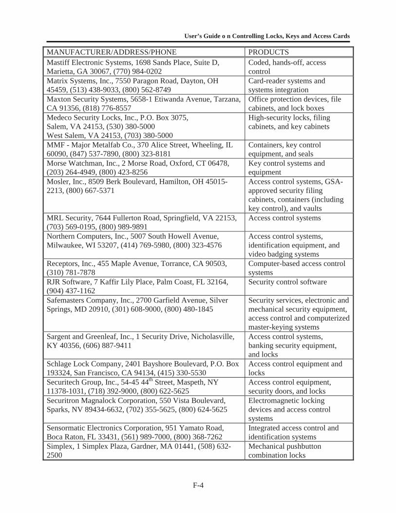
User’s Guide o n Controlling Locks, Keys and Access Cards
F-4
MANUFACTURER/ADDRESS/PHONE PRODUCTSMastiff Electronic Systems, 1698 Sands Place, Suite D,Marietta, GA 30067, (770) 984-0202
Coded, hands-off, accesscontrol
Matrix Systems, Inc., 7550 Paragon Road, Dayton, OH45459, (513) 438-9033, (800) 562-8749
Card-reader systems andsystems integration
Maxton Security Systems, 5658-1 Etiwanda Avenue, Tarzana,CA 91356, (818) 776-8557
Office protection devices, filecabinets, and lock boxes
Medeco Security Locks, Inc., P.O. Box 3075,Salem, VA 24153, (530) 380-5000West Salem, VA 24153, (703) 380-5000
High-security locks, filingcabinets, and key cabinets
MMF - Major Metalfab Co., 370 Alice Street, Wheeling, IL60090, (847) 537-7890, (800) 323-8181
Containers, key controlequipment, and seals
Morse Watchman, Inc., 2 Morse Road, Oxford, CT 06478,(203) 264-4949, (800) 423-8256
Key control systems andequipment
Mosler, Inc., 8509 Berk Boulevard, Hamilton, OH 45015-2213, (800) 667-5371
Access control systems, GSA-approved security filingcabinets, containers (includingkey control), and vaults
MRL Security, 7644 Fullerton Road, Springfield, VA 22153,(703) 569-0195, (800) 989-9891
Access control systems
Northern Computers, Inc., 5007 South Howell Avenue,Milwaukee, WI 53207, (414) 769-5980, (800) 323-4576
Access control systems,identification equipment, andvideo badging systems
Receptors, Inc., 455 Maple Avenue, Torrance, CA 90503,(310) 781-7878
Computer-based access controlsystems
RJR Software, 7 Kaffir Lily Place, Palm Coast, FL 32164,(904) 437-1162
Security control software
Safemasters Company, Inc., 2700 Garfield Avenue, SilverSprings, MD 20910, (301) 608-9000, (800) 480-1845
Security services, electronic andmechanical security equipment,access control and computerizedmaster-keying systems
Sargent and Greenleaf, Inc., 1 Security Drive, Nicholasville,KY 40356, (606) 887-9411
Access control systems,banking security equipment,and locks
Schlage Lock Company, 2401 Bayshore Boulevard, P.O. Box193324, San Francisco, CA 94134, (415) 330-5530
Access control equipment andlocks
Securitech Group, Inc., 54-45 44th Street, Maspeth, NY11378-1031, (718) 392-9000, (800) 622-5625
Access control equipment,security doors, and locks
Securitron Magnalock Corporation, 550 Vista Boulevard,Sparks, NV 89434-6632, (702) 355-5625, (800) 624-5625
Electromagnetic lockingdevices and access controlsystems
Sensormatic Electronics Corporation, 951 Yamato Road,Boca Raton, FL 33431, (561) 989-7000, (800) 368-7262
Integrated access control andidentification systems
Simplex, 1 Simplex Plaza, Gardner, MA 01441, (508) 632-2500
Mechanical pushbuttoncombination locks

User’s Guide o n Controlling Locks, Keys and Access Cards
F-5
MANUFACTURER/ADDRESS/PHONE PRODUCTSSynergistics, Inc., 9 Tech Circle, Natick, MA 01760,(508) 655-1340
Card-reader systems, computer-based access control systems
Supra Products, Inc., 2611 Pringle Road SE, P.O. Box 3167,Salem, OR 97302-0167, (503) 581-9101, (800) 905-3226
Electronic access control(combined with mechanical keycontrol) and access activitytracking
Telkee, 60 Starlifter Avenue, Kent County Aeropark, Dover,DE 19901, (302) 678-7800
Indexed key control containersand systems
Treskat USA, 725 Adriane Park Circle, Kissimmee, FL34744, (407) 870-9696, (800) 645-5657
Key control and keymanagement software forlocksmiths
Trigon Electronics, 1220 North Batavia Street,Orange, CA 92667, (714) 633-7442
Telephone control systems andcard-reader systems
Vikonics, Inc., P.O. Box 2168, South Hackensack, NJ 07606-2168, (201) 641-8077, (800) 626-5416
Computer-based access controlsystems
Yale Security, Inc., P.O. Box 25288, Charlotte, NC 28229-8010, (704) 283-2101, Ext. 140, (800) 438-1951
Mechanical and electronicoperating locks
User’s Guide on Controlling Locks, Keys and Access Cards
G-1
APPENDIX G
CHECKLISTS FOR LOCK AND KEY CONTROL
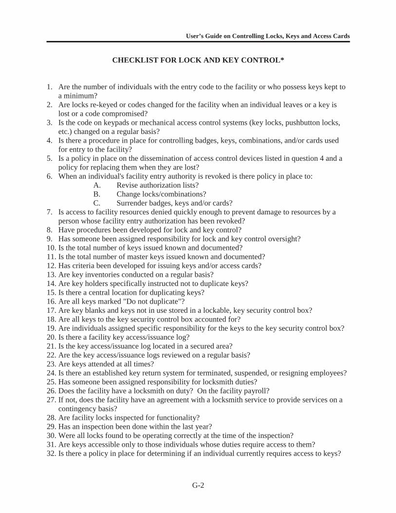
User’s Guide on Controlling Locks, Keys and Access Cards
G-2
CHECKLIST FOR LOCK AND KEY CONTROL*
1. Are the number of individuals with the entry code to the facility or who possess keys kept toa minimum?
2. Are locks re-keyed or codes changed for the facility when an individual leaves or a key islost or a code compromised?
3. Is the code on keypads or mechanical access control systems (key locks, pushbutton locks,etc.) changed on a regular basis?
4. Is there a procedure in place for controlling badges, keys, combinations, and/or cards usedfor entry to the facility?
5. Is a policy in place on the dissemination of access control devices listed in question 4 and apolicy for replacing them when they are lost?
6. When an individual's facility entry authority is revoked is there policy in place to:A. Revise authorization lists?B. Change locks/combinations?C. Surrender badges, keys and/or cards?
7. Is access to facility resources denied quickly enough to prevent damage to resources by aperson whose facility entry authorization has been revoked?
8. Have procedures been developed for lock and key control?9. Has someone been assigned responsibility for lock and key control oversight?10. Is the total number of keys issued known and documented?11. Is the total number of master keys issued known and documented?12. Has criteria been developed for issuing keys and/or access cards?13. Are key inventories conducted on a regular basis?14. Are key holders specifically instructed not to duplicate keys?15. Is there a central location for duplicating keys?16. Are all keys marked "Do not duplicate"?17. Are key blanks and keys not in use stored in a lockable, key security control box?18. Are all keys to the key security control box accounted for?19. Are individuals assigned specific responsibility for the keys to the key security control box?20. Is there a facility key access/issuance log?21. Is the key access/issuance log located in a secured area?22. Are the key access/issuance logs reviewed on a regular basis?23. Are keys attended at all times?24. Is there an established key return system for terminated, suspended, or resigning employees?25. Has someone been assigned responsibility for locksmith duties?26. Does the facility have a locksmith on duty? On the facility payroll?27. If not, does the facility have an agreement with a locksmith service to provide services on a
contingency basis?28. Are facility locks inspected for functionality?29. Has an inspection been done within the last year?30. Were all locks found to be operating correctly at the time of the inspection?31. Are keys accessible only to those individuals whose duties require access to them?32. Is there a policy in place for determining if an individual currently requires access to keys?

User’s Guide on Controlling Locks, Keys and Access Cards
G-3
33. Are keypad-viewing shields used to deny unauthorized observation of entry codes?34. Are doors locked when not in use?35. Are employees discouraged from holding secured doors open for others or allowing follow-
ins?36. Are procedures in place to prevent tailgating?37. Are padlocks locked to hasp when not in use?38. Are locks and frames designed to prohibit the forced spreading of doorframes (e.g., metal
jimmy guards)?
*If the answer to any of these questions is “no,” action should be taken to correct the problemimmediately. See Chapter 3 for further guidance.
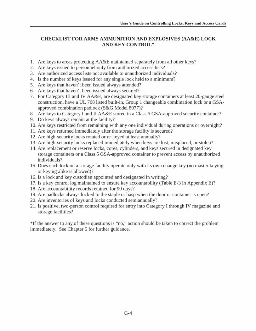
User’s Guide on Controlling Locks, Keys and Access Cards
G-4
CHECKLIST FOR ARMS AMMUNITION AND EXPLOSIVES (AA&E) LOCKAND KEY CONTROL*
1. Are keys to areas protecting AA&E maintained separately from all other keys?2. Are keys issued to personnel only from authorized access lists?3. Are authorized access lists not available to unauthorized individuals?4. Is the number of keys issued for any single lock held to a minimum?5. Are keys that haven’t been issued always attended?6. Are keys that haven’t been issued always secured?7. For Category III and IV AA&E, are designated key storage containers at least 20-gauge steel
construction, have a UL 768 listed built-in, Group 1 changeable combination lock or a GSA-approved combination padlock (S&G Model 8077)?
8. Are keys to Category I and II AA&E stored in a Class 5 GSA-approved security container?9. Do keys always remain at the facility?10. Are keys restricted from remaining with any one individual during operations or overnight?11. Are keys returned immediately after the storage facility is secured?12. Are high-security locks rotated or re-keyed at least annually?13. Are high-security locks replaced immediately when keys are lost, misplaced, or stolen?14. Are replacement or reserve locks, cores, cylinders, and keys secured in designated key
storage containers or a Class 5 GSA-approved container to prevent access by unauthorizedindividuals?
15. Does each lock on a storage facility operate only with its own change key (no master keyingor keying alike is allowed)?
16. Is a lock and key custodian appointed and designated in writing?17. Is a key control log maintained to ensure key accountability (Table E-3 in Appendix E)?18. Are accountability records retained for 90 days?19. Are padlocks always locked to the staple or hasp when the door or container is open?20. Are inventories of keys and locks conducted semiannually?21. Is positive, two-person control required for entry into Category I through IV magazine and
storage facilities?
*If the answer to any of these questions is “no,” action should be taken to correct the problemimmediately. See Chapter 5 for further guidance.
User’s Guide on Controlling Locks, Keys and Access Cards
G-5
CHECKLIST FOR CHEMICAL AND SPECIAL WEAPONS (C&SW) LOCKAND KEY CONTROL*
In addition to the checklist for AA&E, the following apply specifically to the protection ofC&SW:
1. Are keys to chemical or special storage facilities controlled as classified material and storedin a Class 5 security container?
2. Are keys stored separately from all other keys?3. Are keys and locks audited monthly?4. Are keys inventoried with each change of custody?5. Is positive two-person control used for access to all C&SW storage facilities?6. Is a two-key entry system (two separate locking systems or one locking system with two
keys) used to ensure compliance with the two-person requirement?
*If the answer to any of these questions is “no,” action should be taken to correct the problemimmediately. See Chapter 5 for further guidance.