usermanual - thesunpays
TRANSCRIPT
Off Grid Solar InverterSPF 5000TL HVM-WPV
Version: 1.0
User Manual

Table Of Contents1.0 Information on this Manual............................................................................................................................................................ 1
1.1 Validity.....................................................................................................................................................................................1
1.2 Scope........................................................................................................................................................................................1
1.3 Target Group.........................................................................................................................................................................1
1.4 Safety Instructions.............................................................................................................................................................12.0 Introduction.......................................................................................................................................................................................2
2.1 Features..................................................................................................................................................................................2
2.2 Product Overview................................................................................................................................................................33.0 Installation.........................................................................................................................................................................................4
3.1 Unpacking and Inspection...............................................................................................................................................4
3.2 Mounting the Unit............................................................................................................................................................... 4
3.3 Battery Connection.............................................................................................................................................................53.3.1 Lead-acid Battery Connection.........................................................................................................................................53.3.2 Lithium Battery Connection............................................................................................................................................. 6
3.4 AC Input/Output Connection..........................................................................................................................................9
3.5 PV Connection....................................................................................................................................................................10
3.6 Final Assembly...................................................................................................................................................................10
3.7 Communication Connection..........................................................................................................................................11
3.8 Dry Contact Signal............................................................................................................................................................114.0 Operation........................................................................................................................................................................................12
4.1 Power ON/OFF...................................................................................................................................................................12
4.2 Operation and Display Panel........................................................................................................................................ 124.2.1 LCD Display Icons..........................................................................................................................................................134.2.2 LCD Setting......................................................................................................................................................................15
4.3 Display Information.........................................................................................................................................................19
4.4 Operating Mode Description.........................................................................................................................................215.0 Parallel Installation Guide............................................................................................................................................................226.0 Fault Reference Code.................................................................................................................................................................. 337.0 Warning Indicator..........................................................................................................................................................................348.0 Specifications.................................................................................................................................................................................359.0 Trouble Shooting...........................................................................................................................................................................38
1
1.0 Information on this Manual1.1 Validity
This manual is valid for the following devices:SPF 5000TL HVM-WPVSPF 5000TL HVM-WPV-P;
1.2 ScopeThis manual describes the assembly, installation, operation and troubleshooting of this unit. Please readthis manual carefully before installations and operations.
1.3 Target GroupThis document is intended for qualified persons and end users. Tasks that do not require any particularqualification can also be performed by end users. Qualified persons must have the following skills:
Knowledge of how an inverter works and is operatedTraining in how to deal with the dangers and risks associated with installing and using electricaldevices and installationsTraining in the installation and commissioning of electrical devices and installationsKnowledge of the applicable standards and directivesKnowledge of and compliance with this document and all safety information
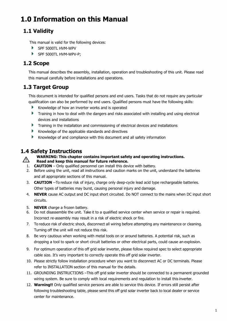
1.4 Safety InstructionsWARNING: This chapter contains important safety and operating instructions.Read and keep this manual for future reference.
1. CAUTION – Only qualified personnel can install this device with battery.2. Before using the unit, read all instructions and caution marks on the unit, understand the batteries
and all appropriate sections of this manual.3. CAUTION --To reduce risk of injury, charge only deep-cycle lead acid type rechargeable batteries.
Other types of batteries may burst, causing personal injury and damage.4. NEVER cause AC output and DC input short circuited. Do NOT connect to the mains when DC input short
circuits.
5. NEVER charge a frozen battery.6. Do not disassemble the unit. Take it to a qualified service center when service or repair is required.
Incorrect re-assembly may result in a risk of electric shock or fire.7. To reduce risk of electric shock, disconnect all wiring before attempting any maintenance or cleaning.
Turning off the unit will not reduce this risk.8. Be very cautious when working with metal tools on or around batteries. A potential risk, such as
dropping a tool to spark or short circuit batteries or other electrical parts, could cause an explosion.
9. For optimum operation of this off grid solar inverter, please follow required spec to select appropriatecable size. It’s very important to correctly operate this off grid solar inverter.
10. Please strictly follow installation procedure when you want to disconnect AC or DC terminals. Pleaserefer to INSTALLATION section of this manual for the details.
11. GROUNDING INSTRUCTIONS –This off grid solar inverter should be connected to a permanent groundedwiring system. Be sure to comply with local requirements and regulation to install this inverter.
12. Warning!! Only qualified service persons are able to service this device. If errors still persist afterfollowing troubleshooting table, please send this off grid solar inverter back to local dealer or servicecenter for maintenance.
2
2.0 Introduction
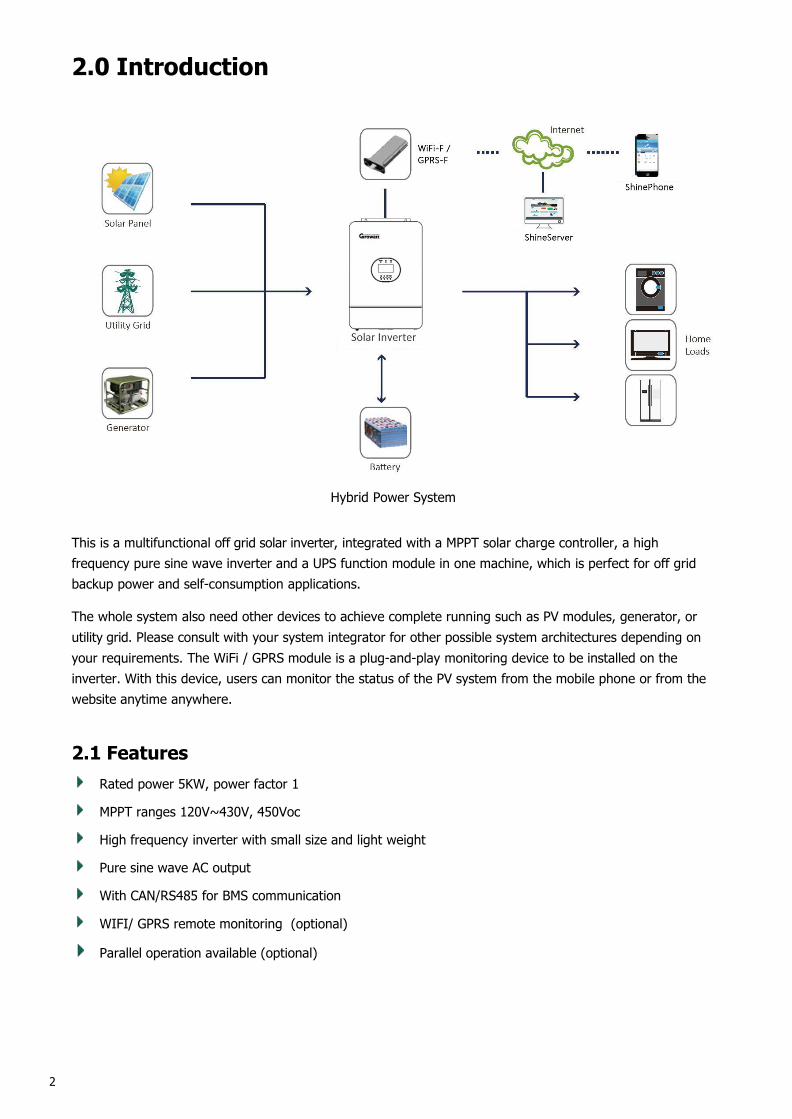
Hybrid Power System
This is a multifunctional off grid solar inverter, integrated with a MPPT solar charge controller, a highfrequency pure sine wave inverter and a UPS function module in one machine, which is perfect for off gridbackup power and self-consumption applications.
The whole system also need other devices to achieve complete running such as PV modules, generator, orutility grid. Please consult with your system integrator for other possible system architectures depending onyour requirements. The WiFi / GPRS module is a plug-and-play monitoring device to be installed on theinverter. With this device, users can monitor the status of the PV system from the mobile phone or from thewebsite anytime anywhere.
2.1 FeaturesRated power 5KW, power factor 1
MPPT ranges 120V~430V, 450Voc
High frequency inverter with small size and light weight
Pure sine wave AC output
With CAN/RS485 for BMS communication
WIFI/ GPRS remote monitoring (optional)
Parallel operation available (optional)
3
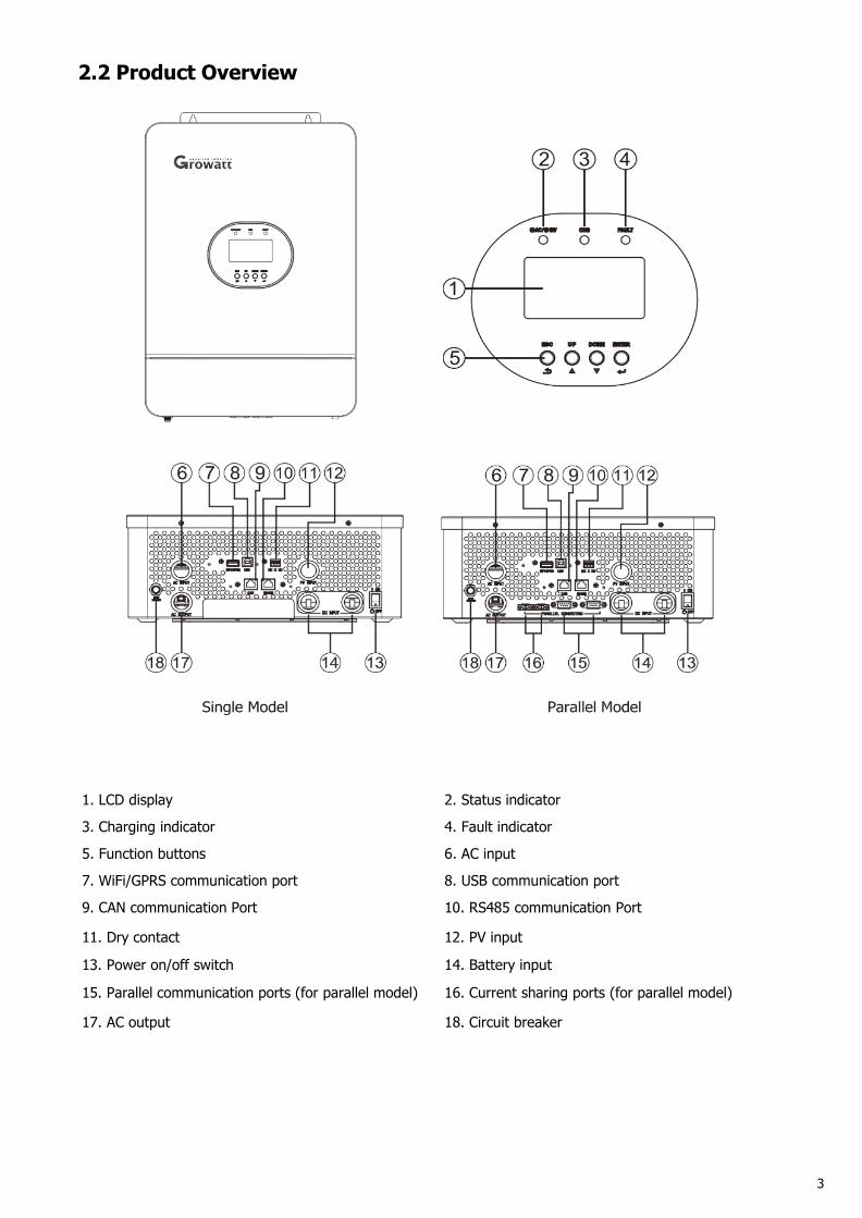
2.2 Product Overview
1. LCD display 2. Status indicator
3. Charging indicator 4. Fault indicator
5. Function buttons 6. AC input
7. WiFi/GPRS communication port 8. USB communication port
9. CAN communication Port 10. RS485 communication Port
11. Dry contact 12. PV input
13. Power on/off switch 14. Battery input
15. Parallel communication ports (for parallel model) 16. Current sharing ports (for parallel model)
17. AC output 18. Circuit breaker
4
3.0 Installation3.1 Unpacking and InspectionBefore installation, please inspect the unit. Be sure that nothing inside the package is damaged. You shouldhave received the following items in the package:
The unit x 1User manual x 1Communication cable x 1Software CD x 1
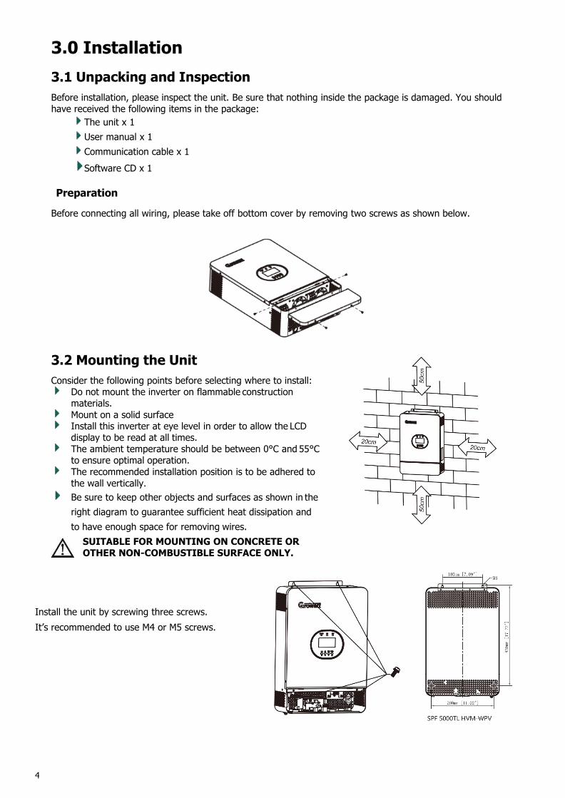
Preparation
Before connecting all wiring, please take off bottom cover by removing two screws as shown below.
3.2 Mounting the UnitConsider the following points before selecting where to install:
Do not mount the inverter on flammable constructionmaterials.Mount on a solid surfaceInstall this inverter at eye level in order to allow the LCDdisplay to be read at all times.The ambient temperature should be between 0°C and 55°Cto ensure optimal operation.The recommended installation position is to be adhered tothe wall vertically.Be sure to keep other objects and surfaces as shown in theright diagram to guarantee sufficient heat dissipation andto have enough space for removing wires.SUITABLE FOR MOUNTING ON CONCRETE OROTHER NON-COMBUSTIBLE SURFACE ONLY.
Install the unit by screwing three screws.It’s recommended to use M4 or M5 screws.
5
3.3 Battery Connection3.3.1 Lead-acid Battery ConnectionUser can choose proper capacity lead acid battery with a nominal voltage at 48V for 5KVA
You need to choose battery type as “AGM(default) or FLD”
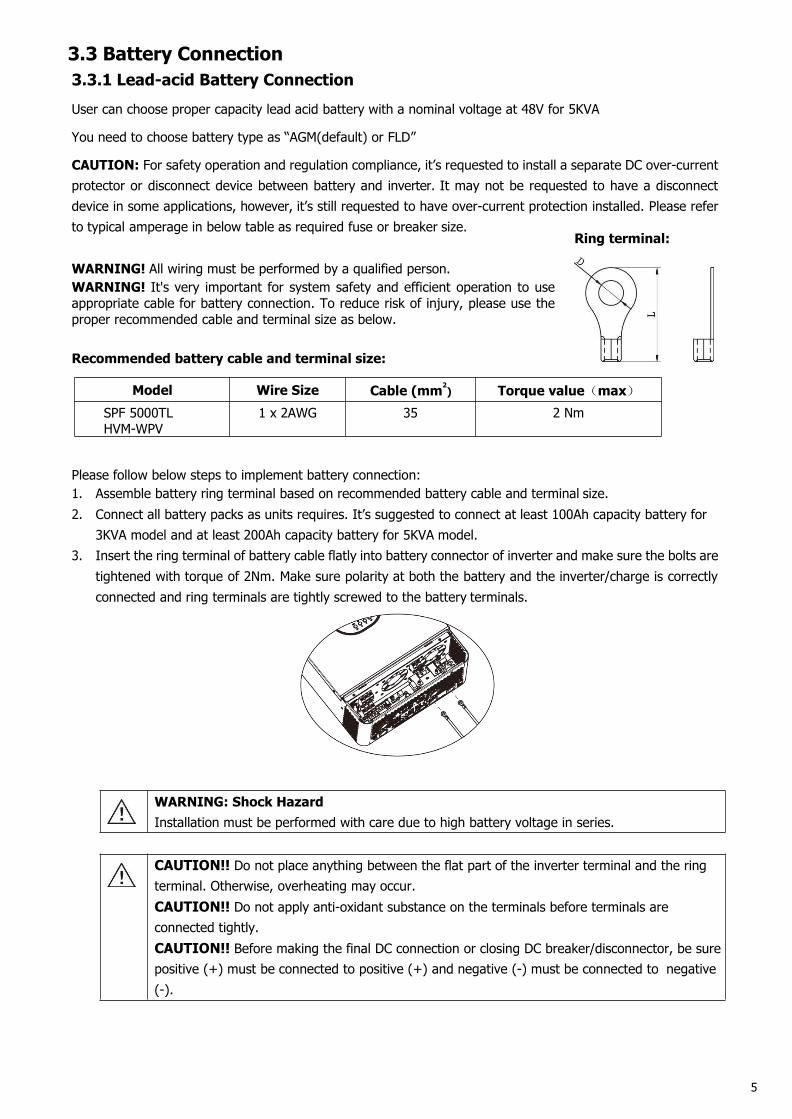
CAUTION: For safety operation and regulation compliance, it’s requested to install a separate DC over-currentprotector or disconnect device between battery and inverter. It may not be requested to have a disconnectdevice in some applications, however, it’s still requested to have over-current protection installed. Please referto typical amperage in below table as required fuse or breaker size.
Ring terminal:
WARNING! All wiring must be performed by a qualified person.WARNING! It's very important for system safety and efficient operation to useappropriate cable for battery connection. To reduce risk of injury, please use theproper recommended cable and terminal size as below.
Recommended battery cable and terminal size:
Model Wire Size Cable (mm2) Torque value(max)
SPF 5000TLHVM-WPV
1 x 2AWG 35 2 Nm
Please follow below steps to implement battery connection:1. Assemble battery ring terminal based on recommended battery cable and terminal size.2. Connect all battery packs as units requires. It’s suggested to connect at least 100Ah capacity battery for
3KVA model and at least 200Ah capacity battery for 5KVA model.3. Insert the ring terminal of battery cable flatly into battery connector of inverter and make sure the bolts are
tightened with torque of 2Nm. Make sure polarity at both the battery and the inverter/charge is correctlyconnected and ring terminals are tightly screwed to the battery terminals.
WARNING: Shock HazardInstallation must be performed with care due to high battery voltage in series.
CAUTION!! Do not place anything between the flat part of the inverter terminal and the ringterminal. Otherwise, overheating may occur.CAUTION!! Do not apply anti-oxidant substance on the terminals before terminals areconnected tightly.CAUTION!! Before making the final DC connection or closing DC breaker/disconnector, be surepositive (+) must be connected to positive (+) and negative (-) must be connected to negative(-).
6
3.3.2 Lithium Battery Connection
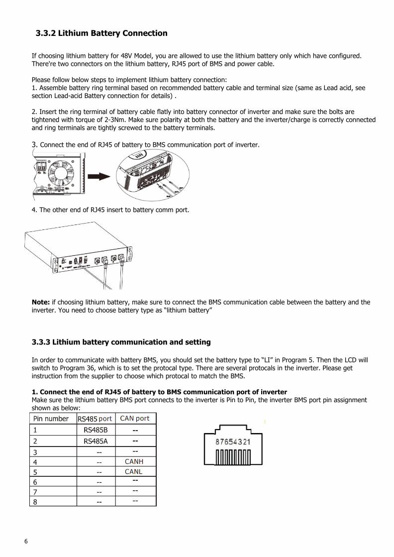
If choosing lithium battery for 48V Model, you are allowed to use the lithium battery only which have configured.There're two connectors on the lithium battery, RJ45 port of BMS and power cable.
Please follow below steps to implement lithium battery connection:1. Assemble battery ring terminal based on recommended battery cable and terminal size (same as Lead acid, seesection Lead-acid Battery connection for details) .
2. Insert the ring terminal of battery cable flatly into battery connector of inverter and make sure the bolts aretightened with torque of 2-3Nm. Make sure polarity at both the battery and the inverter/charge is correctly connectedand ring terminals are tightly screwed to the battery terminals.
3. Connect the end of RJ45 of battery to BMS communication port of inverter.
4. The other end of RJ45 insert to battery comm port.
Note: if choosing lithium battery, make sure to connect the BMS communication cable between the battery and theinverter. You need to choose battery type as “lithium battery”
3.3.3 Lithium battery communication and setting
In order to communicate with battery BMS, you should set the battery type to “LI” in Program 5. Then the LCD willswitch to Program 36, which is to set the protocal type. There are several protocals in the inverter. Please getinstruction from the supplier to choose which protocal to match the BMS.
1. Connect the end of RJ45 of battery to BMS communication port of inverterMake sure the lithium battery BMS port connects to the inverter is Pin to Pin, the inverter BMS port pin assignmentshown as below:
7
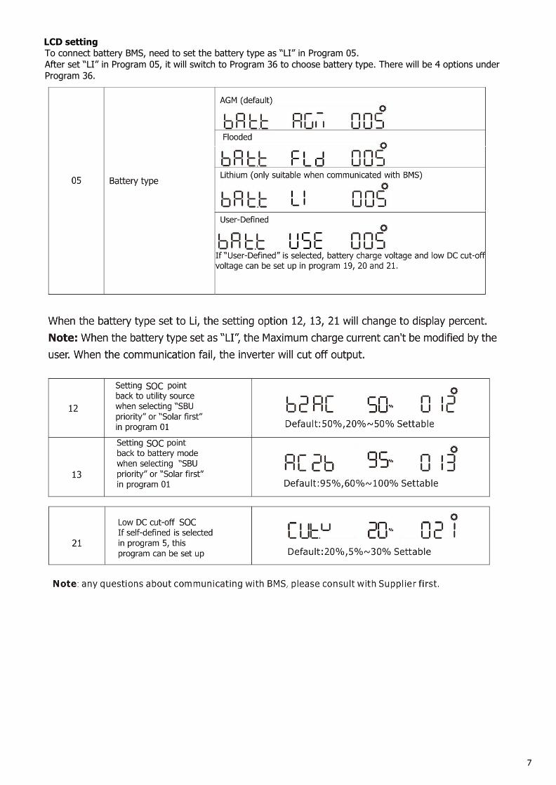
LCD settingTo connect battery BMS, need to set the battery type as “LI” in Program 05.After set “LI” in Program 05, it will switch to Program 36 to choose battery type. There will be 4 options underProgram 36.
8
9
3.4 AC Input/Output ConnectionCAUTION!! Before connecting to AC input power source, please install a separate AC breaker betweeninverter and AC input power source. This will ensure the inverter can be securely disconnected duringmaintenance and fully protected from over current of AC input. The recommended spec of AC breaker is 32Afor 3KVA, 50A for 5KVA.CAUTION!! There are two terminal blocks with “IN” and “OUT” markings. Please do NOT mis-connect inputand output connectors.WARNING! All wiring must be performed by a qualified personnel.WARNING! It’s very important for system safety and efficient operation to use appropriate cable for AC inputconnection. To reduce risk of injury, please use the proper recommended cable size as below.Suggested cable requirement for AC wires
Model Gauge Cable (mm2) Torque ValueSPF 5000TL H
VM-WPV10 AWG 6 1.2 Nm
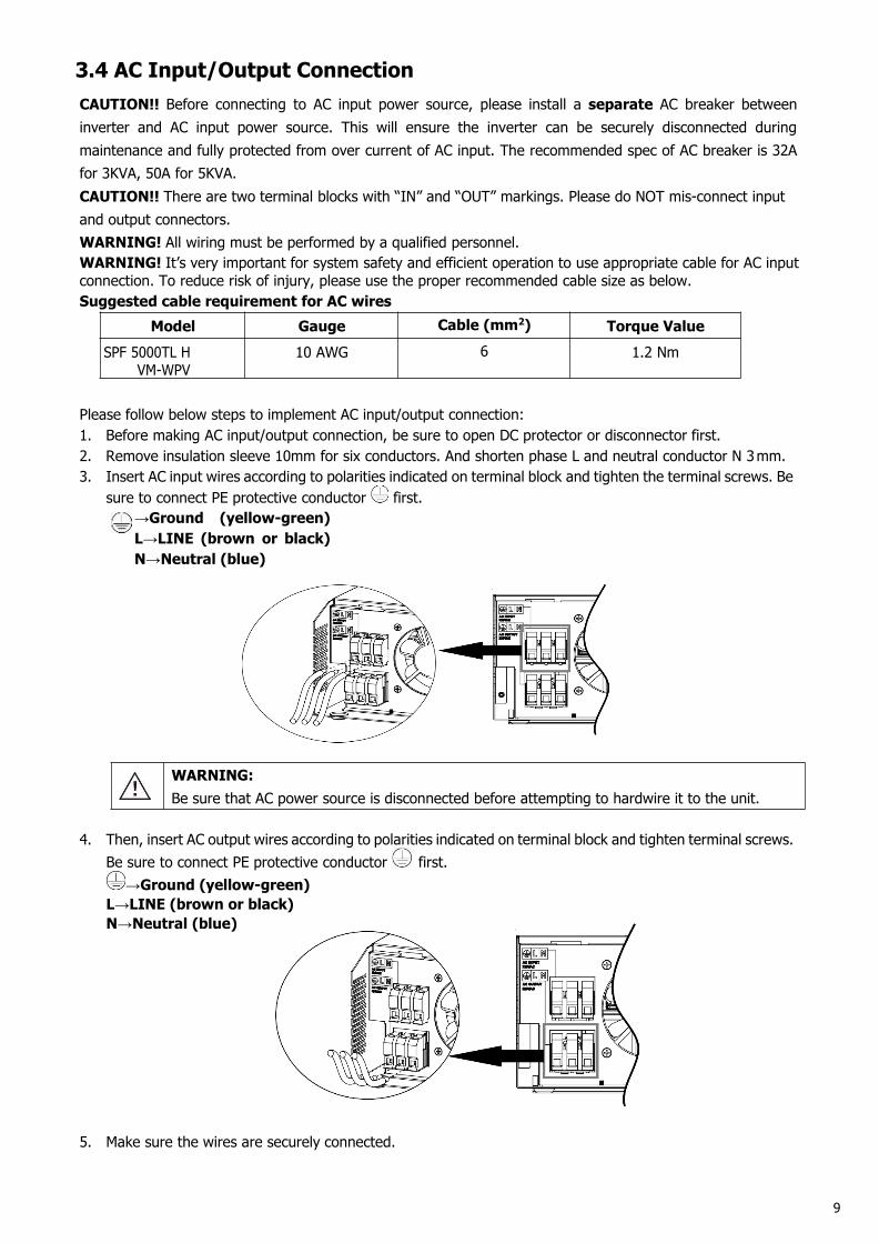
Please follow below steps to implement AC input/output connection:1. Before making AC input/output connection, be sure to open DC protector or disconnector first.2. Remove insulation sleeve 10mm for six conductors. And shorten phase L and neutral conductor N 3mm.3. Insert AC input wires according to polarities indicated on terminal block and tighten the terminal screws. Be
sure to connect PE protective conductor first.→Ground (yellow-green)L→LINE (brown or black)N→Neutral (blue)
WARNING:Be sure that AC power source is disconnected before attempting to hardwire it to the unit.
4. Then, insert AC output wires according to polarities indicated on terminal block and tighten terminal screws.Be sure to connect PE protective conductor first.
→Ground (yellow-green)L→LINE (brown or black)N→Neutral (blue)
5. Make sure the wires are securely connected.
10
CAUTION: Appliances such as air conditioner are required at least 2~3 minutes to restart because it’srequired to have enough time to balance refrigerant gas inside of circuits. If a power shortage occurs andrecovers in a short time, it will cause damage to your connected appliances. To prevent this kind of damage,please check with manufacturer of air conditioner that if it’s equipped with time-delay function beforeinstallation. Otherwise, this off grid solar inverter will trigger overload fault and cut off output to protect yourappliance but sometimes it still causes internal damage to the air conditioner.
3.5 PV ConnectionCAUTION: Before connecting to PV modules, please install separately a DC circuit breaker between inverterand PV modules.
WARNING! All wiring must be performed by a qualified personnel.WARNING! It'’ very important for system safety and efficient operation to use appropriate cable for PV moduleconnection. To reduce risk of injury, please use the proper recommended cable size as below.
Model Wire Size Cable (mm2) Torque value(max)SPF 5000TL HVM-
WPV1 x 12AWG 4 1.2 Nm
PV Module Selection:When selecting proper PV modules, please be sure to consider below parameters:1. Open circuit Voltage (Voc) of PV modules not exceeds max. PV array open circuit voltage of inverter.2. Open circuit Voltage (Voc) of PV modules should be higher than min. battery voltage.
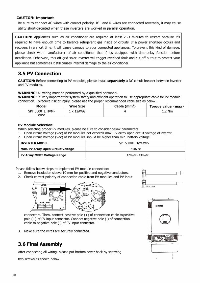
Please follow below steps to implement PV module connection:1. Remove insulation sleeve 10 mm for positive and negative conductors.2. Check correct polarity of connection cable from PV modules and PV input
connectors. Then, connect positive pole (+) of connection cable to positivepole (+) of PV input connector. Connect negative pole (-) of connectioncable to negative pole (-) of PV input connector.
3. Make sure the wires are securely connected.
3.6 Final AssemblyAfter connecting all wiring, please put bottom cover back by screwing
two screws as shown below.
INVERTER MODEL SPF 5000TL HVM-WPV
Max. PV Array Open Circuit Voltage 450Vdc
PV Array MPPT Voltage Range 120Vdc~430Vdc
CAUTION: ImportantBe sure to connect AC wires with correct polarity. If L and N wires are connected reversely, it may causeutility short-circuited when these inverters are worked in parallel operation.
11
3.7 Communication ConnectionPlease use supplied communication cable to connect to inverter and PC. Insert bundled CD into a computer andfollow on-screen instruction to install the monitoring software. For the detailed software operation, pleasecheck user manual of software inside of CD.
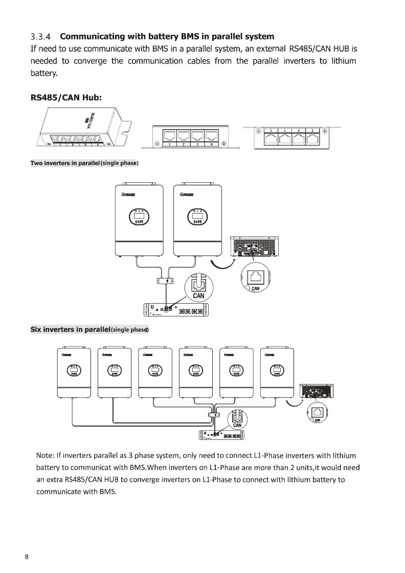
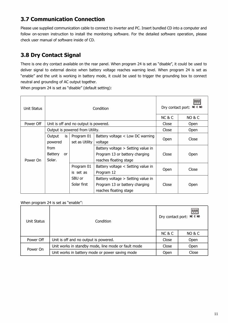
3.8 Dry Contact SignalThere is one dry contact available on the rear panel. When program 24 is set as “disable”, it could be used todeliver signal to external device when battery voltage reaches warning level. When program 24 is set as“enable” and the unit is working in battery mode, it could be used to trigger the grounding box to connectneutral and grounding of AC output together.When program 24 is set as “disable” (default setting):
Unit Status Condition Dry contact port:
NC & C NO & CPower Off Unit is off and no output is powered. Close Open
Power On
Output is powered from Utility. Close OpenOutput ispoweredfromBattery orSolar.
Program 01set as Utility
Battery voltage < Low DC warningvoltage
Open Close
Battery voltage > Setting value inProgram 13 or battery chargingreaches floating stage
Close Open
Program 01is set asSBU orSolar first
Battery voltage < Setting value inProgram 12
Open Close
Battery voltage > Setting value inProgram 13 or battery chargingreaches floating stage
Close Open
When program 24 is set as “enable”:
Unit Status ConditionDry contact port:
NC & C NO & CPower Off Unit is off and no output is powered. Close Open
Power OnUnit works in standby mode, line mode or fault mode Close OpenUnit works in battery mode or power saving mode Open Close
12
4.0 Operation4.1 Power ON/OFF
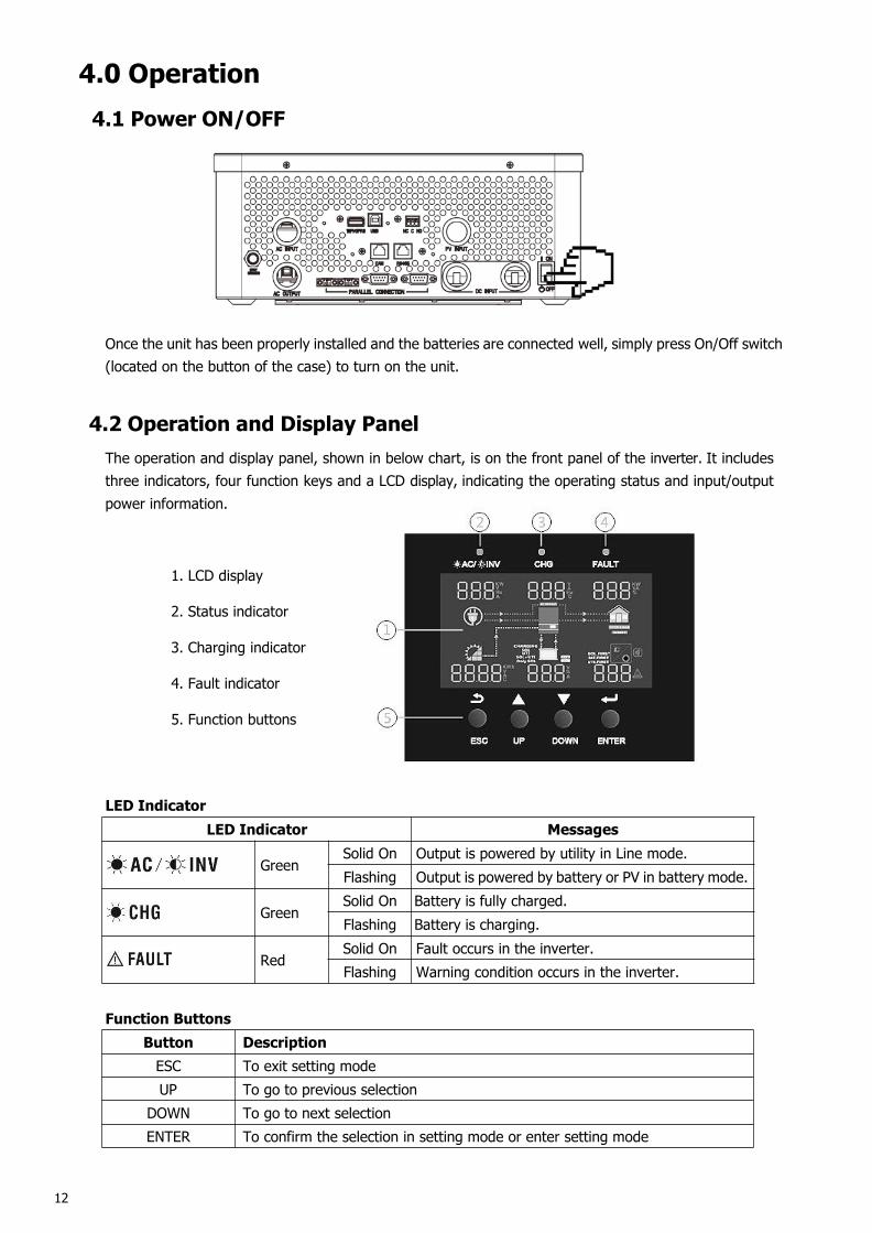
Once the unit has been properly installed and the batteries are connected well, simply press On/Off switch(located on the button of the case) to turn on the unit.
4.2 Operation and Display PanelThe operation and display panel, shown in below chart, is on the front panel of the inverter. It includesthree indicators, four function keys and a LCD display, indicating the operating status and input/outputpower information.
1. LCD display
2. Status indicator
3. Charging indicator
4. Fault indicator
5. Function buttons
LED IndicatorLED Indicator Messages
GreenSolid On Output is powered by utility in Line mode.Flashing Output is powered by battery or PV in battery mode.
GreenSolid On Battery is fully charged.Flashing Battery is charging.
RedSolid On Fault occurs in the inverter.Flashing Warning condition occurs in the inverter.
Function ButtonsButton DescriptionESC To exit setting modeUP To go to previous selection
DOWN To go to next selectionENTER To confirm the selection in setting mode or enter setting mode
13
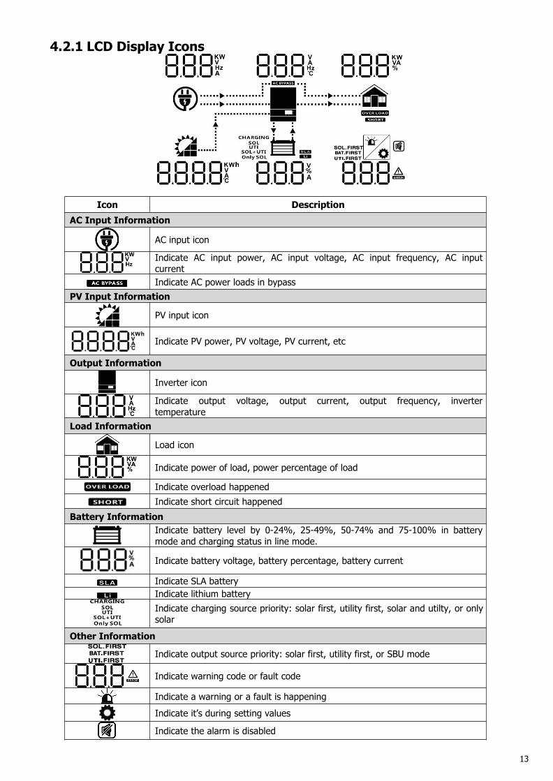
4.2.1 LCD Display Icons
Icon DescriptionAC Input Information
AC input icon
Indicate AC input power, AC input voltage, AC input frequency, AC inputcurrentIndicate AC power loads in bypass
PV Input Information
PV input icon
Indicate PV power, PV voltage, PV current, etc
Output Information
Inverter icon
Indicate output voltage, output current, output frequency, invertertemperature
Load Information
Load icon
Indicate power of load, power percentage of load
Indicate overload happenedIndicate short circuit happened
Battery InformationIndicate battery level by 0-24%, 25-49%, 50-74% and 75-100% in batterymode and charging status in line mode.
Indicate battery voltage, battery percentage, battery current
Indicate SLA batteryIndicate lithium batteryIndicate charging source priority: solar first, utility first, solar and utilty, or onlysolar
Other Information
Indicate output source priority: solar first, utility first, or SBU mode
Indicate warning code or fault code
Indicate a warning or a fault is happeningIndicate it’s during setting values
Indicate the alarm is disabled
14
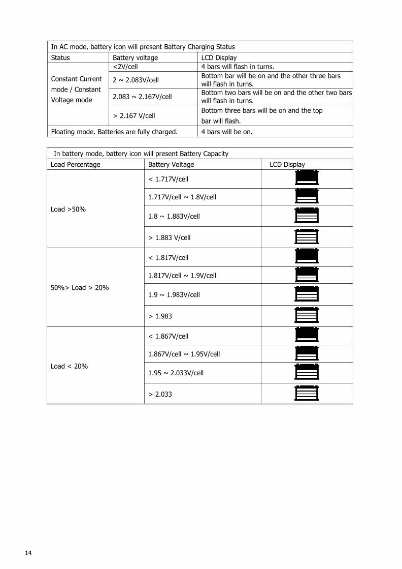
In battery mode, battery icon will present Battery CapacityLoad Percentage Battery Voltage LCD Display
Load >50%
< 1.717V/cell
1.717V/cell ~ 1.8V/cell
1.8 ~ 1.883V/cell
> 1.883 V/cell
50%> Load > 20%
< 1.817V/cell
1.817V/cell ~ 1.9V/cell
1.9 ~ 1.983V/cell
> 1.983
Load < 20%
< 1.867V/cell
1.867V/cell ~ 1.95V/cell
1.95 ~ 2.033V/cell
> 2.033
In AC mode, battery icon will present Battery Charging StatusStatus Battery voltage LCD Display
Constant Currentmode / ConstantVoltage mode
<2V/cell 4 bars will flash in turns.
2 ~ 2.083V/cell Bottom bar will be on and the other three barswill flash in turns.
2.083 ~ 2.167V/cell Bottom two bars will be on and the other two barswill flash in turns.
> 2.167 V/cellBottom three bars will be on and the topbar will flash.
Floating mode. Batteries are fully charged. 4 bars will be on.
15
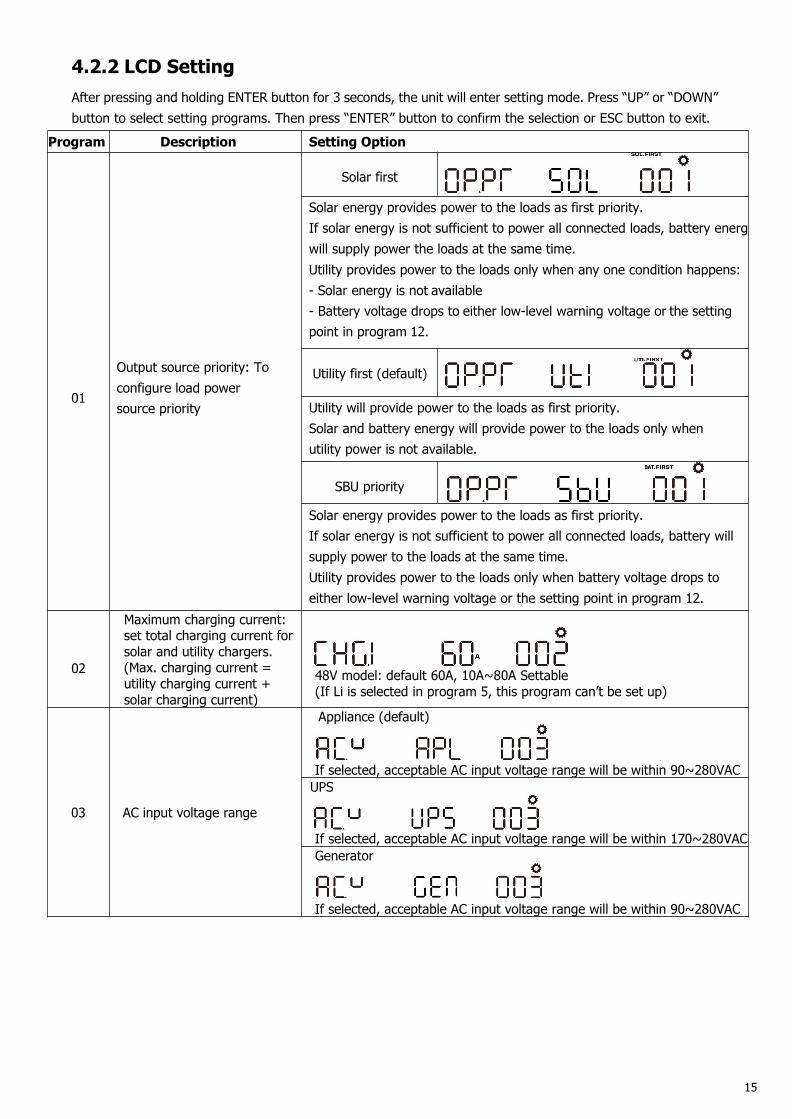
4.2.2 LCD SettingAfter pressing and holding ENTER button for 3 seconds, the unit will enter setting mode. Press “UP” or “DOWN”button to select setting programs. Then press “ENTER” button to confirm the selection or ESC button to exit.
Program Description Setting Option
01
Output source priority: Toconfigure load powersource priority
Solar first
Solar energy provides power to the loads as first priority.If solar energy is not sufficient to power all connected loads, battery energywill supply power the loads at the same time.Utility provides power to the loads only when any one condition happens:- Solar energy is not available- Battery voltage drops to either low-level warning voltage or the settingpoint in program 12.
Utility first (default)
Utility will provide power to the loads as first priority.Solar and battery energy will provide power to the loads only whenutility power is not available.
SBU priority
Solar energy provides power to the loads as first priority.If solar energy is not sufficient to power all connected loads, battery willsupply power to the loads at the same time.Utility provides power to the loads only when battery voltage drops toeither low-level warning voltage or the setting point in program 12.
02
Maximum charging current:set total charging current forsolar and utility chargers.(Max. charging current =utility charging current +solar charging current)
48V model: default 60A, 10A~80A Settable(If Li is selected in program 5, this program can’t be set up)
03 AC input voltage range
Appliance (default)
If selected, acceptable AC input voltage range will be within 90~280VACUPS
If selected, acceptable AC input voltage range will be within 170~280VACGenerator
If selected, acceptable AC input voltage range will be within 90~280VAC
16
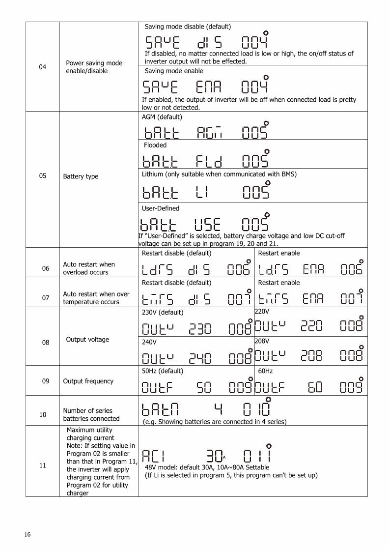
04 Power saving modeenable/disable
Saving mode disable (default)
If disabled, no matter connected load is low or high, the on/off status ofinverter output will not be effected.Saving mode enable
If enabled, the output of inverter will be off when connected load is prettylow or not detected.
05 Battery type
AGM (default)
Flooded
Lithium (only suitable when communicated with BMS)
User-Defined
If “User-Defined” is selected, battery charge voltage and low DC cut-offvoltage can be set up in program 19, 20 and 21.
06 Auto restart whenoverload occurs
Restart disable (default) Restart enable
07 Auto restart when overtemperature occurs
Restart disable (default) Restart enable
08 Output voltage
230V (default) 220V
240V 208V
09 Output frequency50Hz (default) 60Hz
10 Number of seriesbatteries connected (e.g. Showing batteries are connected in 4 series)
11
Maximum utilitycharging currentNote: If setting value inProgram 02 is smallerthan that in Program 11,the inverter will applycharging current fromProgram 02 for utilitycharger
48V model: default 30A, 10A~80A Settable(If Li is selected in program 5, this program can’t be set up)
17
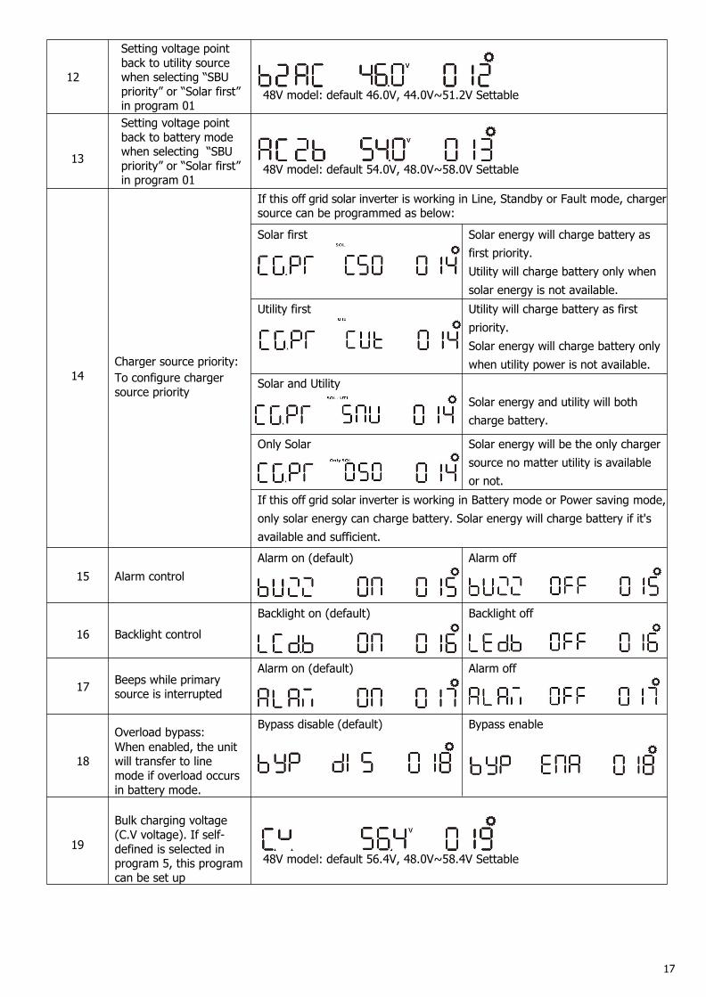
12
Setting voltage pointback to utility sourcewhen selecting “SBUpriority” or “Solar first”in program 01
48V model: default 46.0V, 44.0V~51.2V Settable
13
Setting voltage pointback to battery modewhen selecting “SBUpriority” or “Solar first”in program 01
48V model: default 54.0V, 48.0V~58.0V Settable
14Charger source priority:To configure chargersource priority
If this off grid solar inverter is working in Line, Standby or Fault mode, chargersource can be programmed as below:
Solar first Solar energy will charge battery asfirst priority.Utility will charge battery only whensolar energy is not available.
Utility first Utility will charge battery as firstpriority.Solar energy will charge battery onlywhen utility power is not available.
Solar and UtilitySolar energy and utility will bothcharge battery.
Only Solar Solar energy will be the only chargersource no matter utility is availableor not.
If this off grid solar inverter is working in Battery mode or Power saving mode,only solar energy can charge battery. Solar energy will charge battery if it'savailable and sufficient.
15 Alarm controlAlarm on (default) Alarm off
16 Backlight controlBacklight on (default) Backlight off
17 Beeps while primarysource is interrupted
Alarm on (default) Alarm off
18
Overload bypass:When enabled, the unitwill transfer to linemode if overload occursin battery mode.
Bypass disable (default) Bypass enable
19
Bulk charging voltage(C.V voltage). If self-defined is selected inprogram 5, this programcan be set up
48V model: default 56.4V, 48.0V~58.4V Settable
18
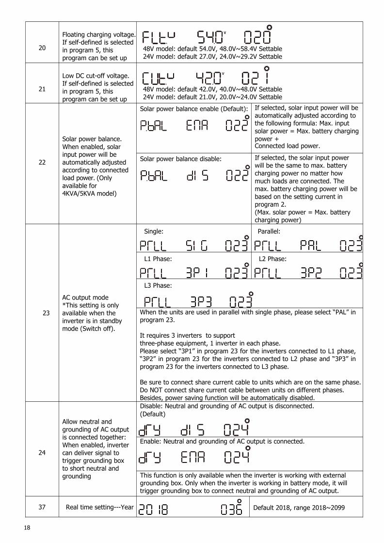
20
Floating charging voltage.If self-defined is selectedin program 5, thisprogram can be set up
48V model: default 54.0V, 48.0V~58.4V Settable24V model: default 27.0V, 24.0V~29.2V Settable
21
Low DC cut-off voltage.If self-defined is selectedin program 5, thisprogram can be set up
48V model: default 42.0V, 40.0V~48.0V Settable24V model: default 21.0V, 20.0V~24.0V Settable
22
Solar power balance.When enabled, solarinput power will beautomatically adjustedaccording to connectedload power. (Onlyavailable for4KVA/5KVA model)
Solar power balance enable (Default): If selected, solar input power will beautomatically adjusted according tothe following formula: Max. inputsolar power = Max. battery chargingpower +Connected load power.
Solar power balance disable: If selected, the solar input powerwill be the same to max. batterycharging power no matter howmuch loads are connected. Themax. battery charging power will bebased on the setting current inprogram 2.(Max. solar power = Max. batterycharging power)
23
AC output mode*This setting is onlyavailable when theinverter is in standbymode (Switch off).
Single: Parallel:
L1 Phase: L2 Phase:
L3 Phase:
When the units are used in parallel with single phase, please select “PAL” inprogram 23.
It requires 3 inverters to supportthree-phase equipment, 1 inverter in each phase.Please select “3P1” in program 23 for the inverters connected to L1 phase,“3P2” in program 23 for the inverters connected to L2 phase and “3P3” inprogram 23 for the inverters connected to L3 phase.
Be sure to connect share current cable to units which are on the same phase.Do NOT connect share current cable between units on different phases.Besides, power saving function will be automatically disabled.
24
Allow neutral andgrounding of AC outputis connected together:When enabled, invertercan deliver signal totrigger grounding boxto short neutral andgrounding
Disable: Neutral and grounding of AC output is disconnected.(Default)
Enable: Neutral and grounding of AC output is connected.
This function is only available when the inverter is working with externalgrounding box. Only when the inverter is working in battery mode, it willtrigger grounding box to connect neutral and grounding of AC output.
37 Real time setting---Year Default 2018, range 2018~2099
19
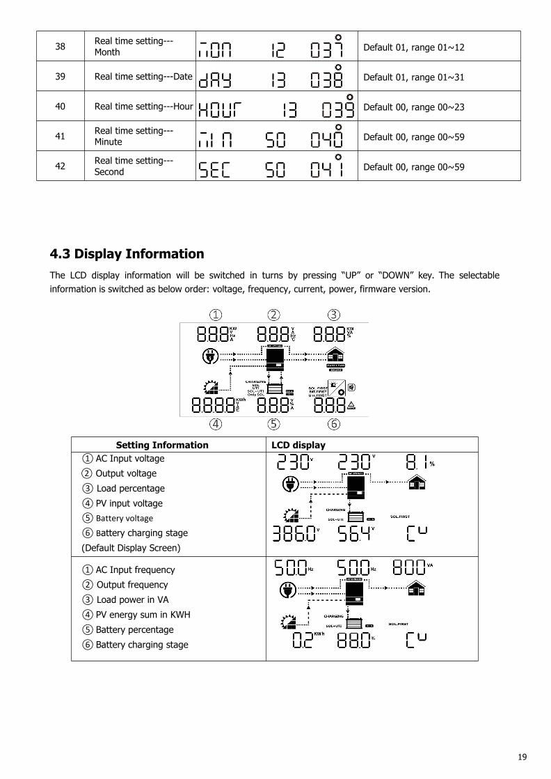
38 Real time setting---Month Default 01, range 01~12
39 Real time setting---Date Default 01, range 01~31
40 Real time setting---Hour Default 00, range 00~23
41 Real time setting---Minute Default 00, range 00~59
42 Real time setting---Second Default 00, range 00~59
4.3 Display InformationThe LCD display information will be switched in turns by pressing “UP” or “DOWN” key. The selectableinformation is switched as below order: voltage, frequency, current, power, firmware version.
Setting Information LCD display① AC Input voltage② Output voltage③ Load percentage④ PV input voltage⑤Battery voltage
⑥ Battery charging stage(Default Display Screen)
① AC Input frequency② Output frequency③ Load power in VA④ PV energy sum in KWH⑤ Battery percentage⑥ Battery charging stage
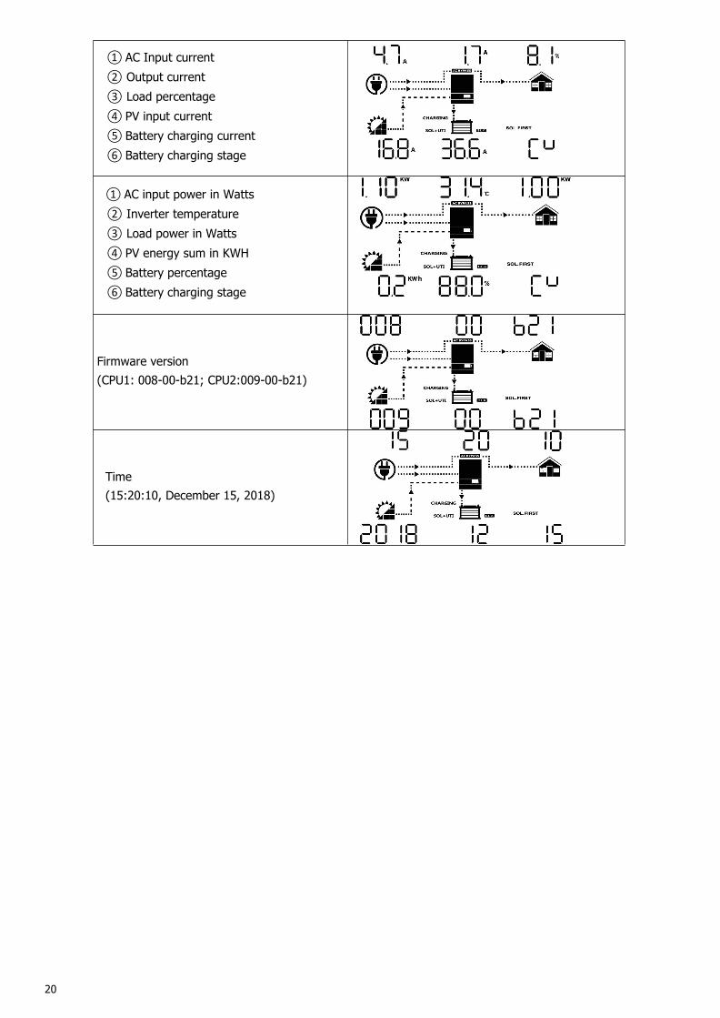
20
① AC Input current② Output current③ Load percentage④ PV input current⑤ Battery charging current⑥ Battery charging stage
① AC input power in Watts② Inverter temperature③ Load power in Watts④ PV energy sum in KWH⑤ Battery percentage⑥ Battery charging stage
Firmware version(CPU1: 008-00-b21; CPU2:009-00-b21)
Time(15:20:10, December 15, 2018)
21
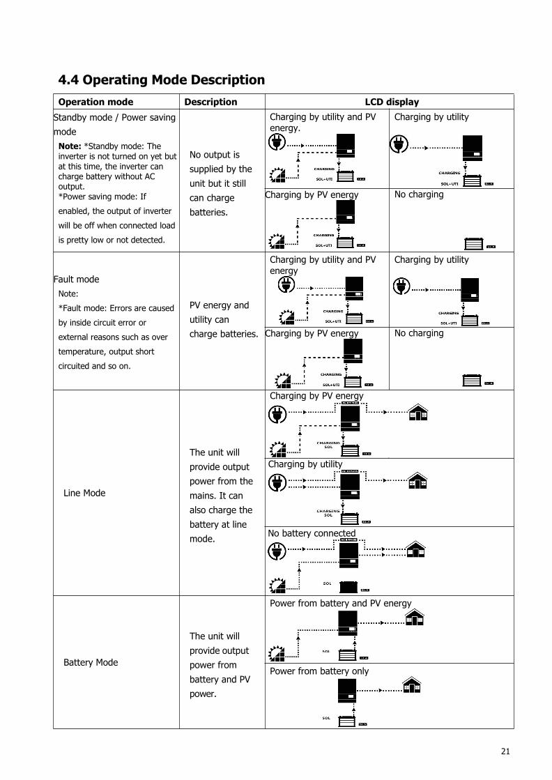
4.4 Operating Mode DescriptionOperation mode Description LCD displayStandby mode / Power savingmodeNote: *Standby mode: Theinverter is not turned on yet butat this time, the inverter cancharge battery without ACoutput.*Power saving mode: Ifenabled, the output of inverterwill be off when connected loadis pretty low or not detected.
No output issupplied by theunit but it stillcan chargebatteries.
Charging by utility and PVenergy.
Charging by utility
Charging by PV energy No charging
Fault modeNote:*Fault mode: Errors are causedby inside circuit error orexternal reasons such as overtemperature, output shortcircuited and so on.
PV energy andutility cancharge batteries.
Charging by utility and PVenergy
Charging by utility
Charging by PV energy No charging
Line Mode
The unit willprovide outputpower from themains. It canalso charge thebattery at linemode.
Charging by PV energy
Charging by utility
No battery connected
Battery Mode
The unit willprovide outputpower frombattery and PVpower.
Power from battery and PV energy
Power from battery only
22
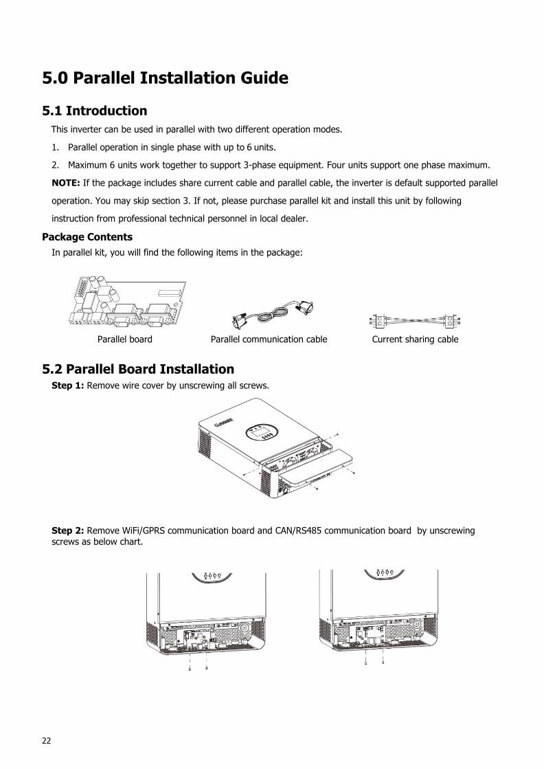
5.0 Parallel Installation Guide
5.1 IntroductionThis inverter can be used in parallel with two different operation modes.
1. Parallel operation in single phase with up to 6 units.
2. Maximum 6 units work together to support 3-phase equipment. Four units support one phase maximum.
NOTE: If the package includes share current cable and parallel cable, the inverter is default supported parallel
operation. You may skip section 3. If not, please purchase parallel kit and install this unit by following
instruction from professional technical personnel in local dealer.
Package ContentsIn parallel kit, you will find the following items in the package:
Parallel board Parallel communication cable Current sharing cable
5.2 Parallel Board InstallationStep 1: Remove wire cover by unscrewing all screws.
Step 2: Remove WiFi/GPRS communication board and CAN/RS485 communication board by unscrewingscrews as below chart.
23
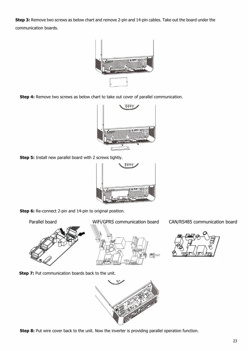
Step 3: Remove two screws as below chart and remove 2-pin and 14-pin cables. Take out the board under the
communication boards.
Step 4: Remove two screws as below chart to take out cover of parallel communication.
Step 5: Install new parallel board with 2 screws tightly.
Step 6: Re-connect 2-pin and 14-pin to original position.
Parallel board WiFi/GPRS communication board CAN/RS485 communication board
Step 7: Put communication boards back to the unit.
Step 8: Put wire cover back to the unit. Now the inverter is providing parallel operation function.
24
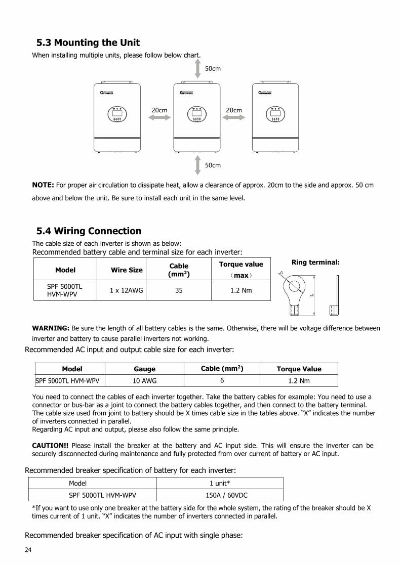
5.3 Mounting the UnitWhen installing multiple units, please follow below chart.
NOTE: For proper air circulation to dissipate heat, allow a clearance of approx. 20cm to the side and approx. 50 cm
above and below the unit. Be sure to install each unit in the same level.
5.4 Wiring ConnectionThe cable size of each inverter is shown as below:Recommended battery cable and terminal size for each inverter:
Ring terminal:
WARNING: Be sure the length of all battery cables is the same. Otherwise, there will be voltage difference betweeninverter and battery to cause parallel inverters not working.
Recommended AC input and output cable size for each inverter:
Model Gauge Cable (mm2) Torque ValueSPF 5000TL HVM-WPV 10 AWG 6 1.2 Nm
You need to connect the cables of each inverter together. Take the battery cables for example: You need to use aconnector or bus-bar as a joint to connect the battery cables together, and then connect to the battery terminal.The cable size used from joint to battery should be X times cable size in the tables above. “X” indicates the numberof inverters connected in parallel.Regarding AC input and output, please also follow the same principle.
CAUTION!! Please install the breaker at the battery and AC input side. This will ensure the inverter can besecurely disconnected during maintenance and fully protected from over current of battery or AC input.
Recommended breaker specification of battery for each inverter:Model 1 unit*SPF 5000TL HVM-WPV 150A / 60VDC
*If you want to use only one breaker at the battery side for the whole system, the rating of the breaker should be Xtimes current of 1 unit. “X” indicates the number of inverters connected in parallel.
Recommended breaker specification of AC input with single phase:
Model Wire Size Cable(mm2)
Torque value(max)
SPF 5000TLHVM-WPV 1 x 12AWG 35 1.2 Nm
25
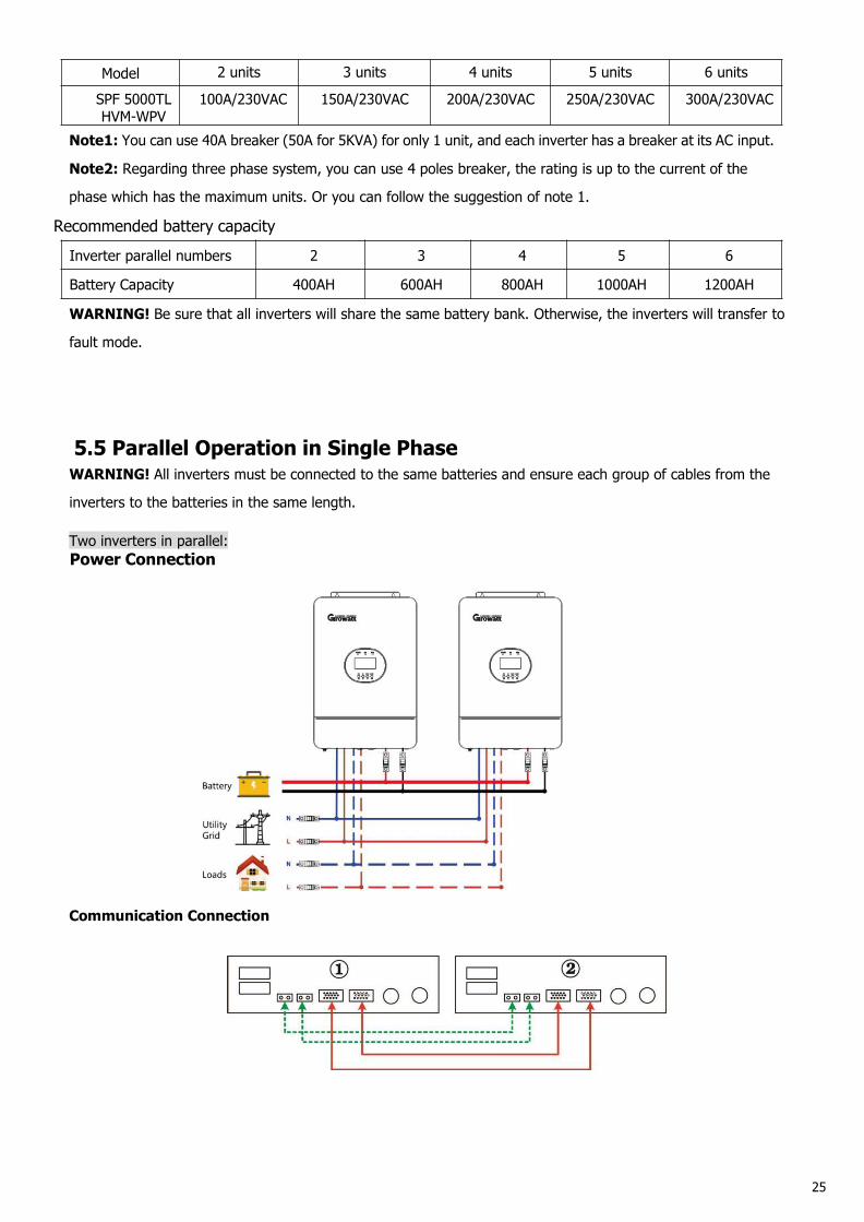
Model 2 units 3 units 4 units 5 units 6 units
SPF 5000TLHVM-WPV
100A/230VAC 150A/230VAC 200A/230VAC 250A/230VAC 300A/230VAC
Note1: You can use 40A breaker (50A for 5KVA) for only 1 unit, and each inverter has a breaker at its AC input.
Note2: Regarding three phase system, you can use 4 poles breaker, the rating is up to the current of the
phase which has the maximum units. Or you can follow the suggestion of note 1.
Recommended battery capacityInverter parallel numbers 2 3 4 5 6
Battery Capacity 400AH 600AH 800AH 1000AH 1200AH
WARNING! Be sure that all inverters will share the same battery bank. Otherwise, the inverters will transfer to
fault mode.
5.5 Parallel Operation in Single PhaseWARNING! All inverters must be connected to the same batteries and ensure each group of cables from the
inverters to the batteries in the same length.
Two inverters in parallel:Power Connection
Communication Connection
26
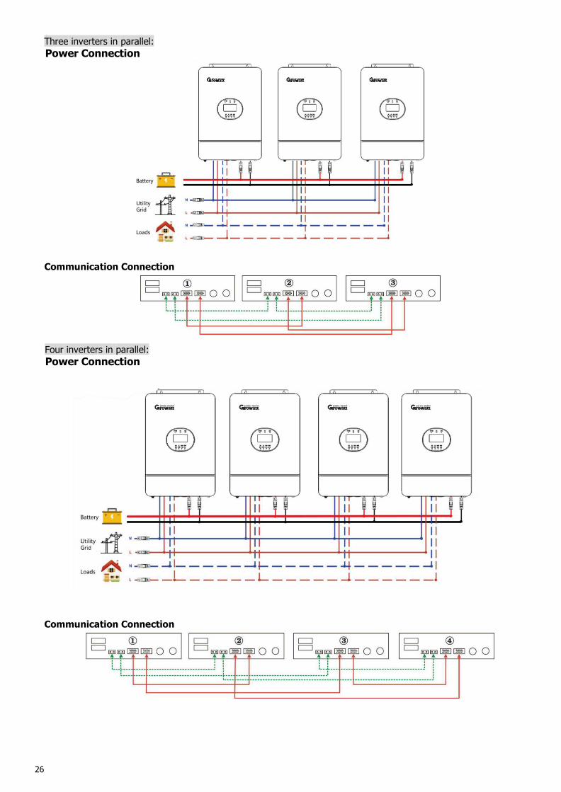
Three inverters in parallel:Power Connection
Communication Connection
Four inverters in parallel:Power Connection
Communication Connection
27
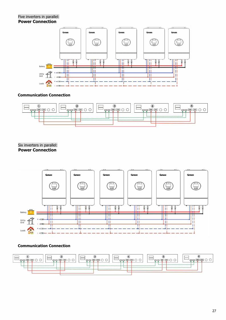
Five inverters in parallel:Power Connection
Communication Connection
Six inverters in parallel:Power Connection
Communication Connection
28
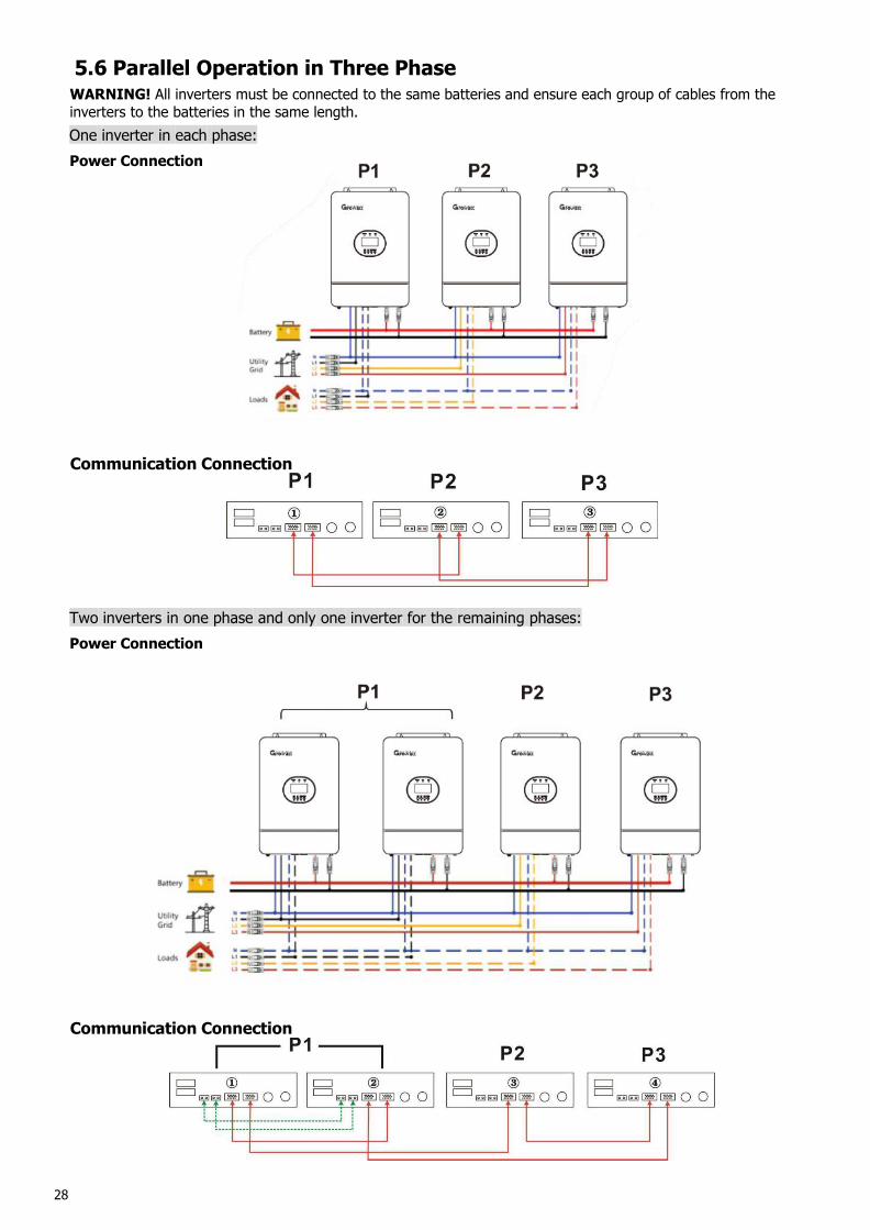
5.6 Parallel Operation in Three PhaseWARNING! All inverters must be connected to the same batteries and ensure each group of cables from theinverters to the batteries in the same length.One inverter in each phase:Power Connection
Communication Connection
Two inverters in one phase and only one inverter for the remaining phases:Power Connection
Communication Connection
29
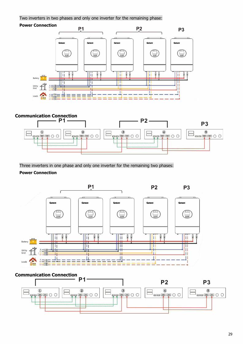
Two inverters in two phases and only one inverter for the remaining phase:Power Connection
Communication Connection
Three inverters in one phase and only one inverter for the remaining two phases:Power Connection
Communication Connection
30
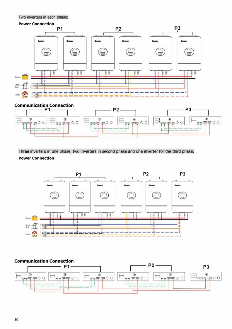
Two inverters in each phase:Power Connection
Communication Connection
Three inverters in one phase, two inverters in second phase and one inverter for the third phase:Power Connection
Communication Connection
31
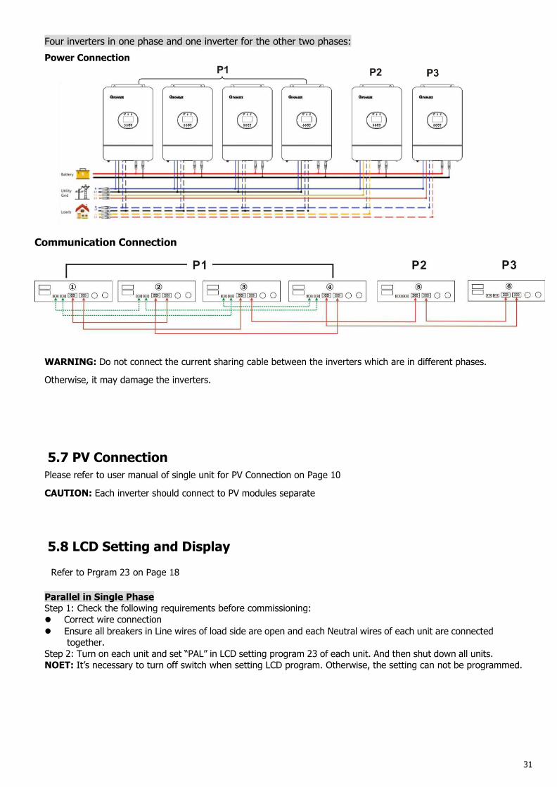
Four inverters in one phase and one inverter for the other two phases:Power Connection
Communication Connection
WARNING: Do not connect the current sharing cable between the inverters which are in different phases.
Otherwise, it may damage the inverters.
5.7 PV ConnectionPlease refer to user manual of single unit for PV Connection on Page 10
CAUTION: Each inverter should connect to PV modules separate
5.8 LCD Setting and Display
Refer to Prgram 23 on Page 18
Parallel in Single PhaseStep 1: Check the following requirements before commissioning: Correct wire connection Ensure all breakers in Line wires of load side are open and each Neutral wires of each unit are connected
together.Step 2: Turn on each unit and set “PAL” in LCD setting program 23 of each unit. And then shut down all units.NOET: It’s necessary to turn off switch when setting LCD program. Otherwise, the setting can not be programmed.
32
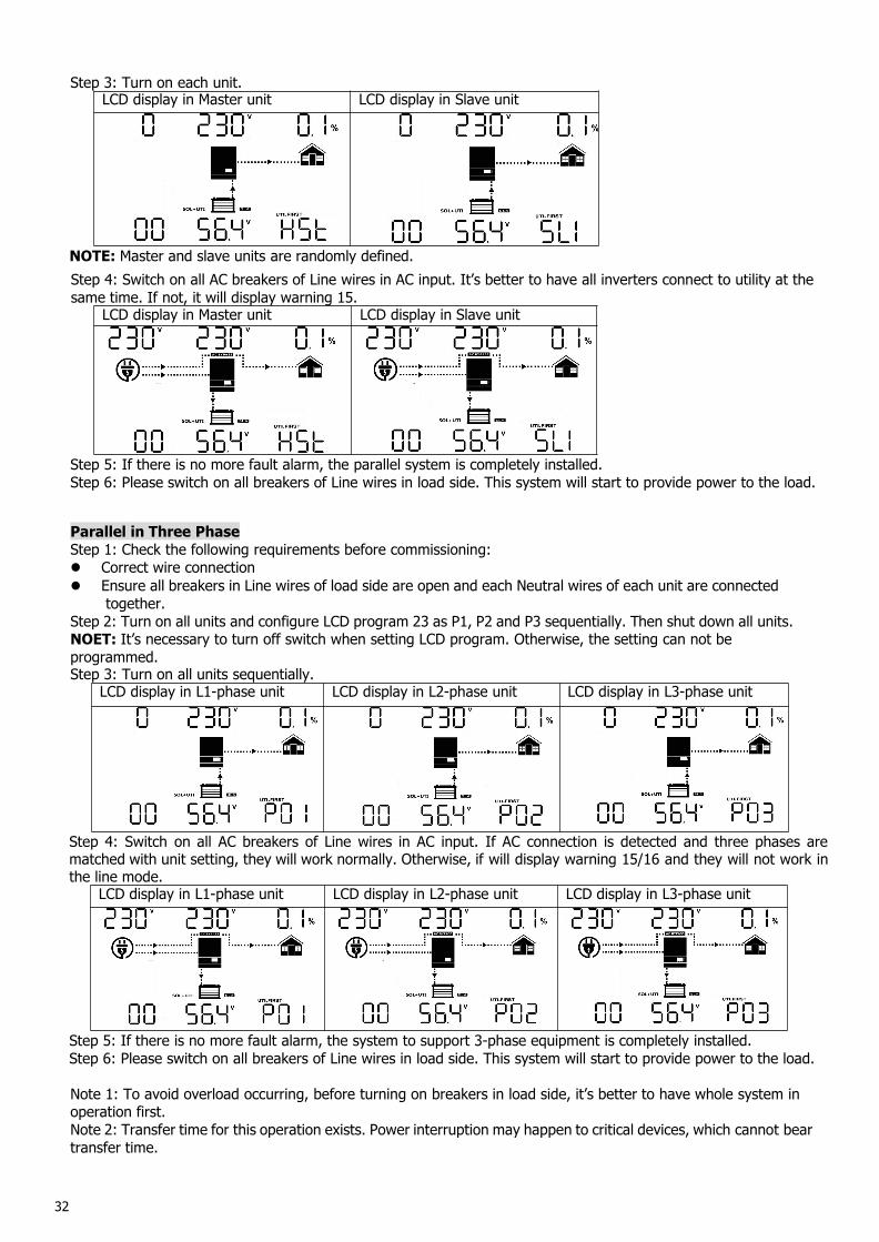
Step 3: Turn on each unit.LCD display in Master unit LCD display in Slave unit
NOTE: Master and slave units are randomly defined.Step 4: Switch on all AC breakers of Line wires in AC input. It’s better to have all inverters connect to utility at thesame time. If not, it will display warning 15.
LCD display in Master unit LCD display in Slave unit
Step 5: If there is no more fault alarm, the parallel system is completely installed.Step 6: Please switch on all breakers of Line wires in load side. This system will start to provide power to the load.
Parallel in Three PhaseStep 1: Check the following requirements before commissioning: Correct wire connection Ensure all breakers in Line wires of load side are open and each Neutral wires of each unit are connected
together.Step 2: Turn on all units and configure LCD program 23 as P1, P2 and P3 sequentially. Then shut down all units.NOET: It’s necessary to turn off switch when setting LCD program. Otherwise, the setting can not beprogrammed.Step 3: Turn on all units sequentially.
LCD display in L1-phase unit LCD display in L2-phase unit LCD display in L3-phase unit
Step 4: Switch on all AC breakers of Line wires in AC input. If AC connection is detected and three phases arematched with unit setting, they will work normally. Otherwise, if will display warning 15/16 and they will not work inthe line mode.
LCD display in L1-phase unit LCD display in L2-phase unit LCD display in L3-phase unit
Step 5: If there is no more fault alarm, the system to support 3-phase equipment is completely installed.Step 6: Please switch on all breakers of Line wires in load side. This system will start to provide power to the load.
Note 1: To avoid overload occurring, before turning on breakers in load side, it’s better to have whole system inoperation first.Note 2: Transfer time for this operation exists. Power interruption may happen to critical devices, which cannot beartransfer time.
33
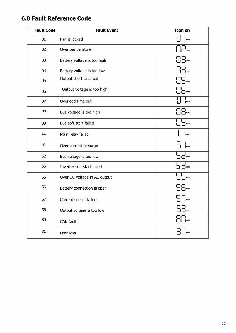
6.0 Fault Reference Code
Fault Code Fault Event Icon on
01 Fan is locked
02 Over temperature
03 Battery voltage is too high
04 Battery voltage is too low
05 Output short circuited
06 Output voltage is too high.
07 Overload time out
08 Bus voltage is too high
09 Bus soft start failed
11 Main relay failed
51 Over current or surge
52 Bus voltage is too low
53 Inverter soft start failed
55 Over DC voltage in AC output
56 Battery connection is open
57 Current sensor failed
58 Output voltage is too low
80 CAN fault
81 Host loss
34
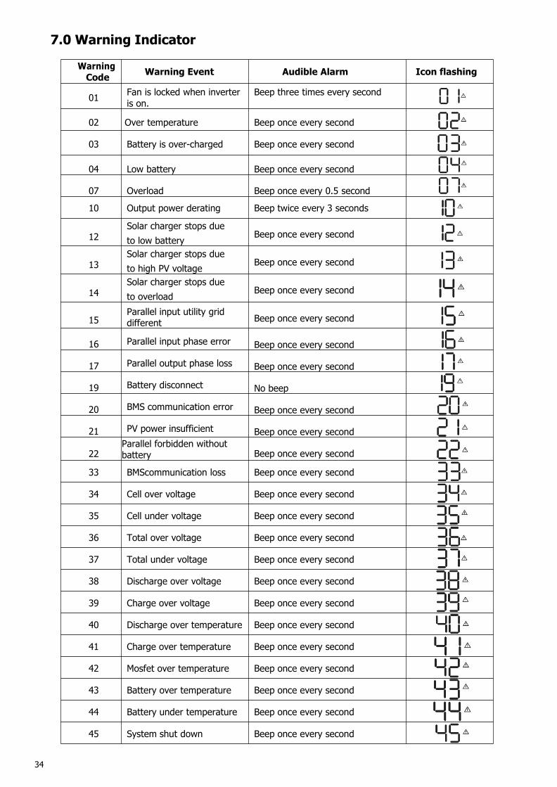
7.0 Warning Indicator
WarningCode Warning Event Audible Alarm Icon flashing
01 Fan is locked when inverteris on.
Beep three times every second
02 Over temperature Beep once every second
03 Battery is over-charged Beep once every second
04 Low battery Beep once every second
07 Overload Beep once every 0.5 second
10 Output power derating Beep twice every 3 seconds
12Solar charger stops dueto low battery Beep once every second
13Solar charger stops dueto high PV voltage Beep once every second
14Solar charger stops dueto overload Beep once every second
15Parallel input utility griddifferent Beep once every second
16 Parallel input phase error Beep once every second
17 Parallel output phase loss Beep once every second
19 Battery disconnect No beep
20 BMS communication error Beep once every second
21 PV power insufficient Beep once every second
22Parallel forbidden withoutbattery Beep once every second
33 BMScommunication loss Beep once every second
34 Cell over voltage Beep once every second
35 Cell under voltage Beep once every second
36 Total over voltage Beep once every second
37 Total under voltage Beep once every second
38 Discharge over voltage Beep once every second
39 Charge over voltage Beep once every second
40 Discharge over temperature Beep once every second
41 Charge over temperature Beep once every second
42 Mosfet over temperature Beep once every second
43 Battery over temperature Beep once every second
44 Battery under temperature Beep once every second
45 System shut down Beep once every second
35
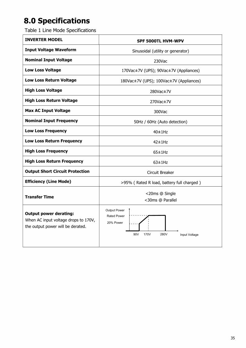
8.0 SpecificationsTable 1 Line Mode Specifications
INVERTER MODEL SPF 5000TL HVM-WPV
Input Voltage Waveform Sinusoidal (utility or generator)
Nominal Input Voltage 230Vac
Low Loss Voltage 170Vac±7V (UPS); 90Vac±7V (Appliances)
Low Loss Return Voltage 180Vac±7V (UPS); 100Vac±7V (Appliances)
High Loss Voltage 280Vac±7V
High Loss Return Voltage 270Vac±7V
Max AC Input Voltage 300Vac
Nominal Input Frequency 50Hz / 60Hz (Auto detection)
Low Loss Frequency 40±1Hz
Low Loss Return Frequency 42±1Hz
High Loss Frequency 65±1Hz
High Loss Return Frequency 63±1Hz
Output Short Circuit Protection Circuit Breaker
Efficiency (Line Mode) >95% ( Rated R load, battery full charged )
Transfer Time<20ms @ Single<30ms @ Parallel
Output power derating:When AC input voltage drops to 170V,the output power will be derated.
Output Power
Rated Power
20% Power
90V 170V 280V Input Voltage
36
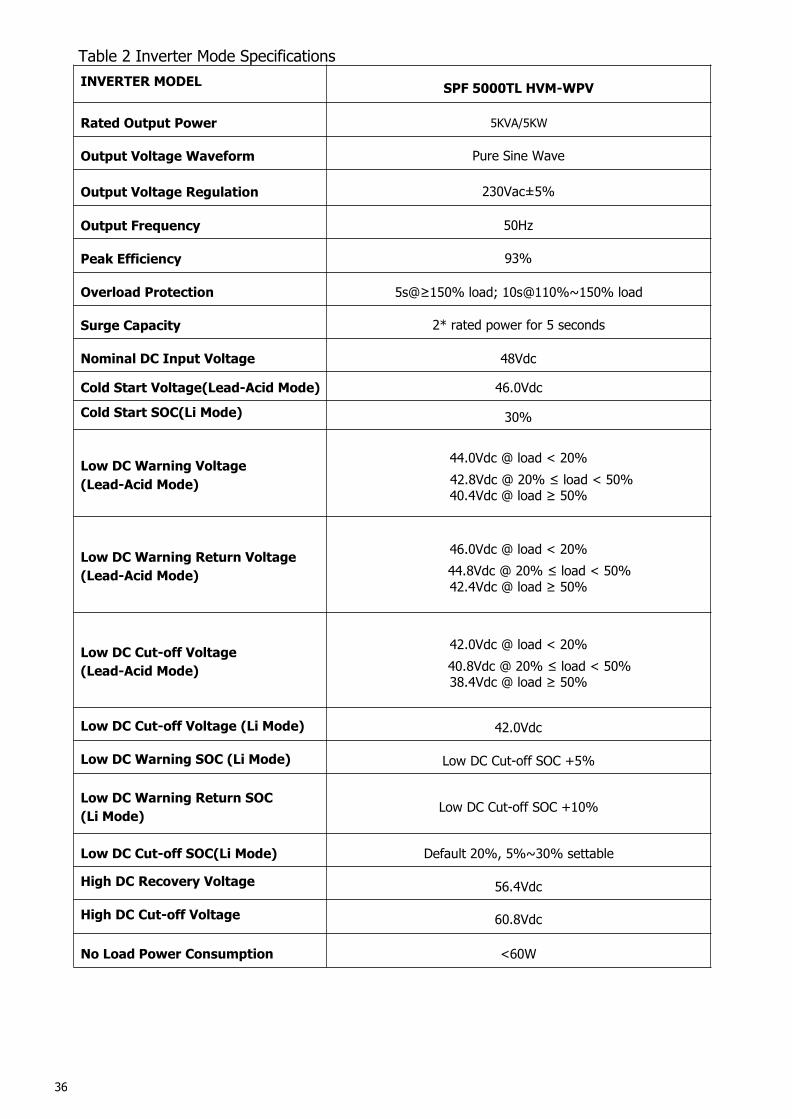
Table 2 Inverter Mode SpecificationsINVERTER MODEL SPF 5000TL HVM-WPV
Rated Output Power 5KVA/5KW
Output Voltage Waveform Pure Sine Wave
Output Voltage Regulation 230Vac±5%
Output Frequency 50Hz
Peak Efficiency 93%
Overload Protection 5s@≥150% load; 10s@110%~150% load
Surge Capacity 2* rated power for 5 seconds
Nominal DC Input Voltage 48Vdc
Cold Start Voltage(Lead-Acid Mode) 46.0Vdc
Cold Start SOC(Li Mode) 30%
Low DC Warning Voltage(Lead-Acid Mode)
44.0Vdc @ load < 20%42.8Vdc @ 20% ≤ load < 50%40.4Vdc @ load ≥ 50%
Low DC Warning Return Voltage(Lead-Acid Mode)
46.0Vdc @ load < 20%44.8Vdc @ 20% ≤ load < 50%42.4Vdc @ load ≥ 50%
Low DC Cut-off Voltage(Lead-Acid Mode)
42.0Vdc @ load < 20%40.8Vdc @ 20% ≤ load < 50%38.4Vdc @ load ≥ 50%
Low DC Cut-off Voltage (Li Mode) 42.0Vdc
Low DC Warning SOC (Li Mode) Low DC Cut-off SOC +5%
Low DC Warning Return SOC(Li Mode) Low DC Cut-off SOC +10%
Low DC Cut-off SOC(Li Mode) Default 20%, 5%~30% settable
High DC Recovery Voltage 56.4Vdc
High DC Cut-off Voltage 60.8Vdc
No Load Power Consumption <60W
37
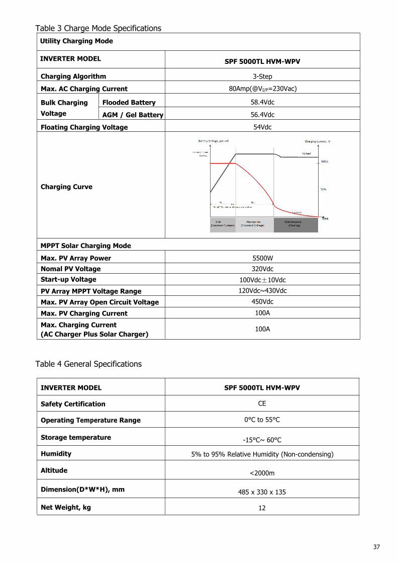
Table 3 Charge Mode SpecificationsUtility Charging Mode
INVERTER MODEL SPF 5000TL HVM-WPV
Charging Algorithm 3-Step
Max. AC Charging Current 80Amp(@VI/P=230Vac)
Bulk ChargingVoltage
Flooded Battery 58.4Vdc
AGM / Gel Battery 56.4Vdc
Floating Charging Voltage 54Vdc
Charging Curve
MPPT Solar Charging Mode
Max. PV Array Power 5500WNomal PV Voltage 320VdcStart-up Voltage 100Vdc±10VdcPV Array MPPT Voltage Range 120Vdc~430VdcMax. PV Array Open Circuit Voltage 450VdcMax. PV Charging Current 100AMax. Charging Current(AC Charger Plus Solar Charger)
100A
Table 4 General Specifications
INVERTER MODEL SPF 5000TL HVM-WPV
Safety Certification CE
Operating Temperature Range 0°C to 55°C
Storage temperature -15°C~ 60°C
Humidity 5% to 95% Relative Humidity (Non-condensing)
Altitude <2000m
Dimension(D*W*H), mm 485 x 330 x 135
Net Weight, kg 12
38
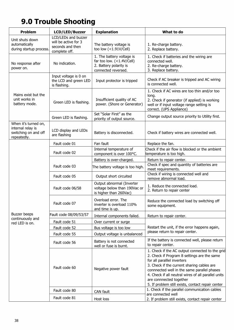
9.0 Trouble ShootingProblem LCD/LED/Buzzer Explanation What to do
Unit shuts downautomaticallyduring startup process.
LCD/LEDs and buzzerwill be active for 3seconds and thencomplete off.
The battery voltage istoo low (<1.91V/Cell)
1. Re-charge battery.2. Replace battery.
No response afterpower on.
No indication.
1. The battery voltage isfar too low. (<1.4V/Cell)2. Battery polarity isconnected reversed.
1. Check if batteries and the wiring areconnected well.2. Re-charge battery.3. Replace battery.
Mains exist but theunit works inbattery mode.
Input voltage is 0 onthe LCD and green LEDis flashing.
Input protector is tripped Check if AC breaker is tripped and AC wiringis connected well.
Green LED is flashing. Insufficient quality of ACpower. (Shore or Generator)
1. Check if AC wires are too thin and/or toolong.2. Check if generator (if applied) is workingwell or if input voltage range setting iscorrect. (UPS Appliance)
Green LED is flashing.Set “Solar First” as thepriority of output source. Change output source priority to Utility first.
When it’s turned on,internal relay isswitching on and offrepeatedly.
LCD display and LEDsare flashing Battery is disconnected. Check if battery wires are connected well.
Buzzer beepscontinuously andred LED is on.
Fault code 01 Fan fault Replace the fan.
Fault code 02Internal temperature ofcomponent is over 100°C.
Check if the air flow is blocked or the ambienttemperature is too high.
Fault code 03Battery is over-charged. Return to repair center.
The battery voltage is too high. Check if spec and quantity of batteries aremeet requirements.
Fault code 05 Output short circuited Check if wiring is connected well andremove abnormal load.
Fault code 06/58Output abnormal (Invertervoltage below than 190Vac oris higher than 260Vac)
1. Reduce the connected load.2. Return to repair center
Fault code 07Overload error. Theinverter is overload 110%and time is up.
Reduce the connected load by switching offsome equipment.
Fault code 08/09/53/57 Internal components failed. Return to repair center.Fault code 51 Over current or surge
Restart the unit, if the error happens again,please return to repair center.
Fault code 52 Bus voltage is too lowFault code 55 Output voltage is unbalanced
Fault code 56 Battery is not connectedwell or fuse is burnt.
If the battery is connected well, please returnto repair center.
Fault code 60 Negative power fault
1. Check if the AC output connected to the grid2. Check if Program 8 settings are the samefor all paralllel inverters3. Check if the current sharing cables areconnnected well in the same parallel phases4. Check if all neutral wires of all parallel unitsare connnected together5. If problem still exists, contact repair center
Fault code 80 CAN fault 1. Check if the parallel communication cablesare connected well2. If problem still exists, contact repair centerFault code 81 Host loss