user s manual solar inverter/charger · pv3000 mpk 1kw~6kw user's manual 100% pure sine wave...
TRANSCRIPT
PV3000 MPK 1KW~6KW
USER'S MANUAL
100% PURE SINE WAVE SOLAR INVERTER
solar Inverter/Charger SOLAR INVERTER/CHARGER
420-00245-01
LCD Display Icons
Operating Mode Description
Warning code/Audible Alarm
6
5
5
6
7
8
21
20
21
21
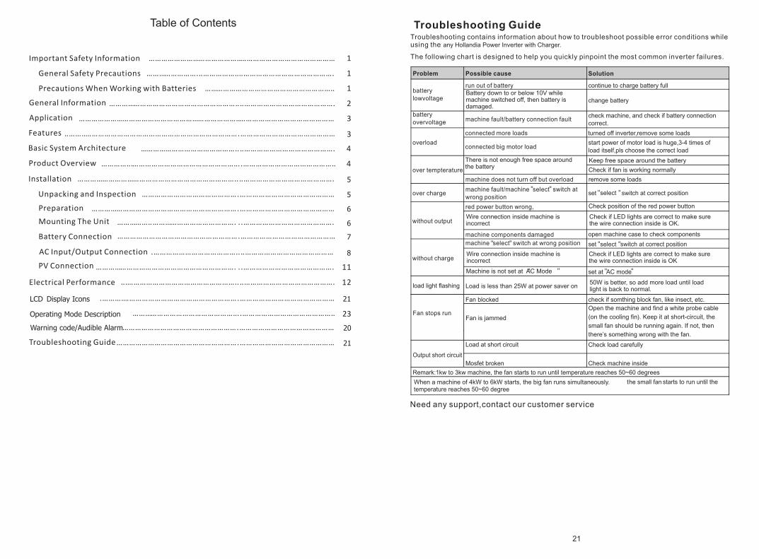
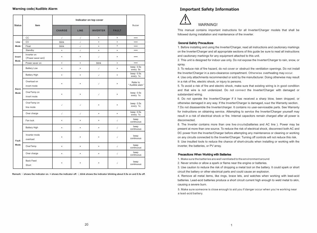
any Hollandia Power Inverter with Charger.
Battery down to or below 10V while machine switched off, then battery is damaged.
There is not enough free space around the battery
Keep free space around the battery
Check if fan is working normally
select
Wire connection inside machine is incorrect
Check position of the red power button
Check if LED lights are correct to make sure the wire connection inside is OK.
select
Wire connection inside machine is incorrect
Check if LED lights are correct to make sure the wire connection inside is OK
Machine is not set at AC Mode
Load is less than 25W at power saver on50W is better, so add more load until load light is back to normal.
Fan is jammed
When a machine of 4kW to 6kW starts, the big fan runs simultaneously.
degrees
Open the machine and find a white probe cable
(on the cooling fin). Keep it at short-circuit, the
small fan should be running again. If not, then
there’s something wrong with the fan.
20
Warning code/Audible Alarm
The series inverter can also
Battery capacity
comeltion
7
,
19
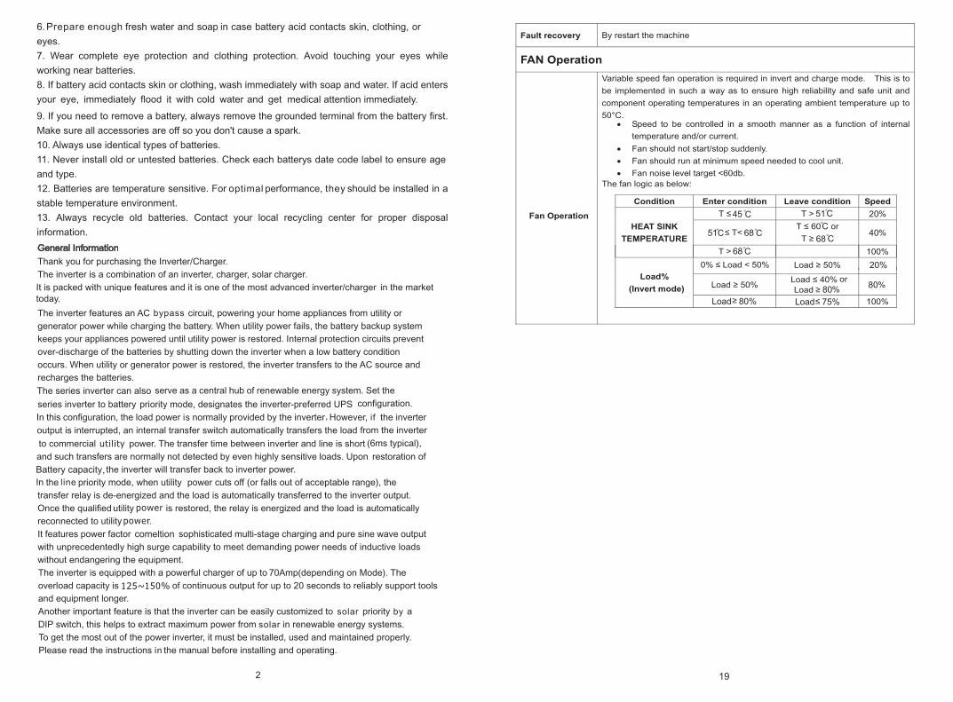
51 68
51
6840
45 20
80
68
C
C
C
C
C
C
20%
Load 80% Load 75%
80
C
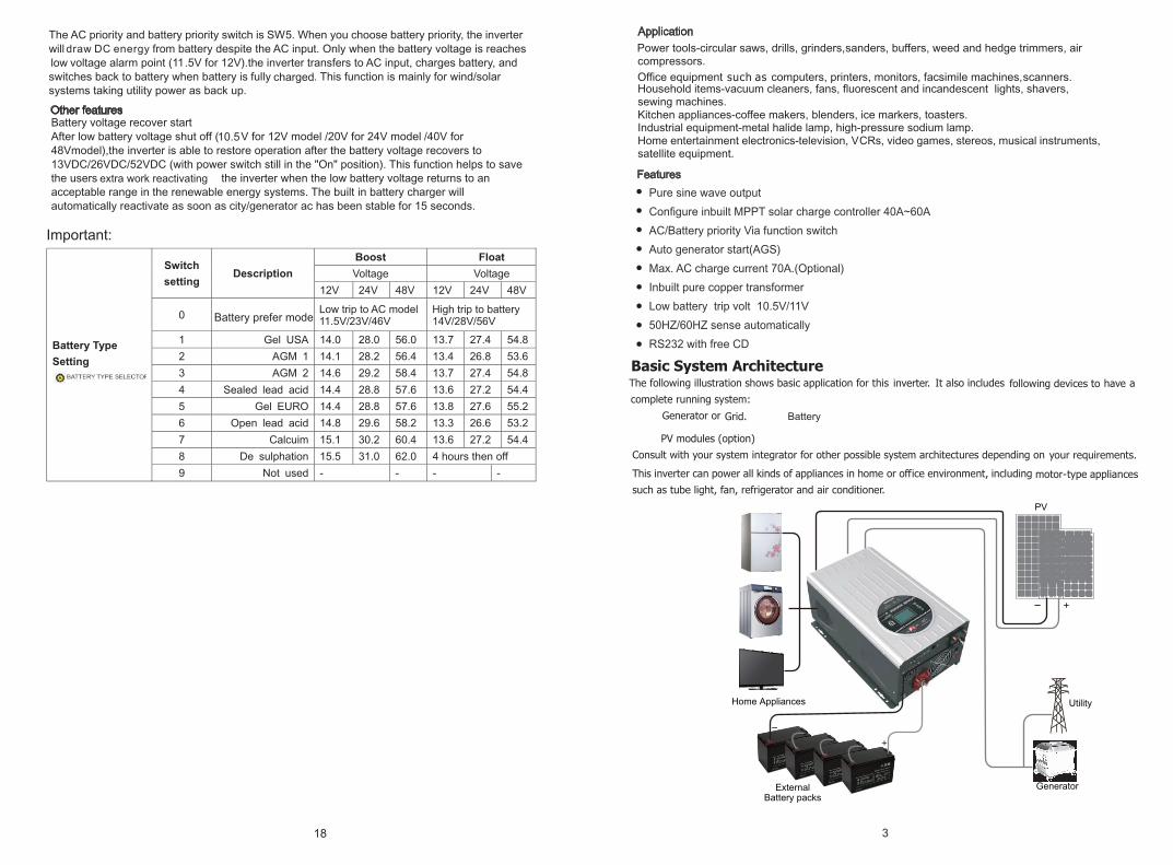
Pure sine wave output
Inbuilt MPPT solar charge controller 30A~60A
Battery priority function
12V/24V/48V input optional
Max. AC charge current 70A.(Optional)
Inbuilt pure copper transformer
LCD status display
50HZ/60HZ sense automatically
RS232 with free CD(optional)
Pure sine wave output
Configure inbuilt MPPT solar charge controller 40A~60A
AC/Battery priority Via function switch
Auto generator start(AGS)
Max. AC charge current 70A.(Optional)
Inbuilt pure copper transformer
Low battery trip volt 10.5V/11V
50HZ/60HZ sense automatically
RS232 with free CD
Battery
18
extra work reactivating
High trip to battery14V/28V/56V
Low trip to AC model11.5V/23V/46V
10.5
432
9
56
8
7
1
11
10
2.
3.
4.
9.
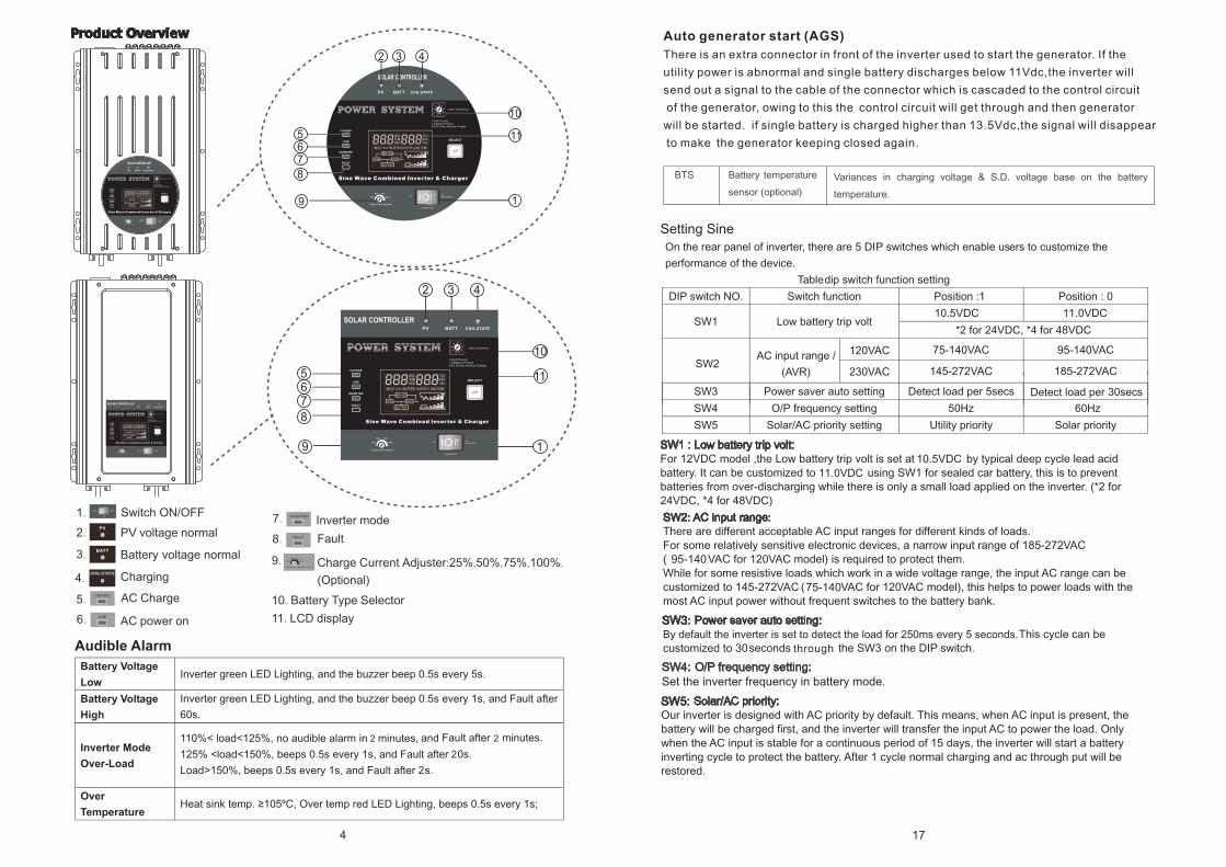
PV voltage normal
Battery voltage normal
Charging
AC power on
Inverter mode
Fault
Charge Current Adjuster:25%,50%,75%,100 .%
(Optional)
5.CHARGE
6. LINE
7. INVERTER
8. FAULT
10. Battery Type Selector
11. LCD display
19
56
8
7
3
11
10
42
1.
AC Charge
Switch ON/OFF
4 17
By default the inverter is set to detect the load for 250ms every 5 seconds.
145-272
185-272
Set the inverter frequency in battery mode.
Setting Sine
95-140
75-140
120VAC
230VAC
75-140VAC
145-272VAC
95-140VAC
185-272VAC
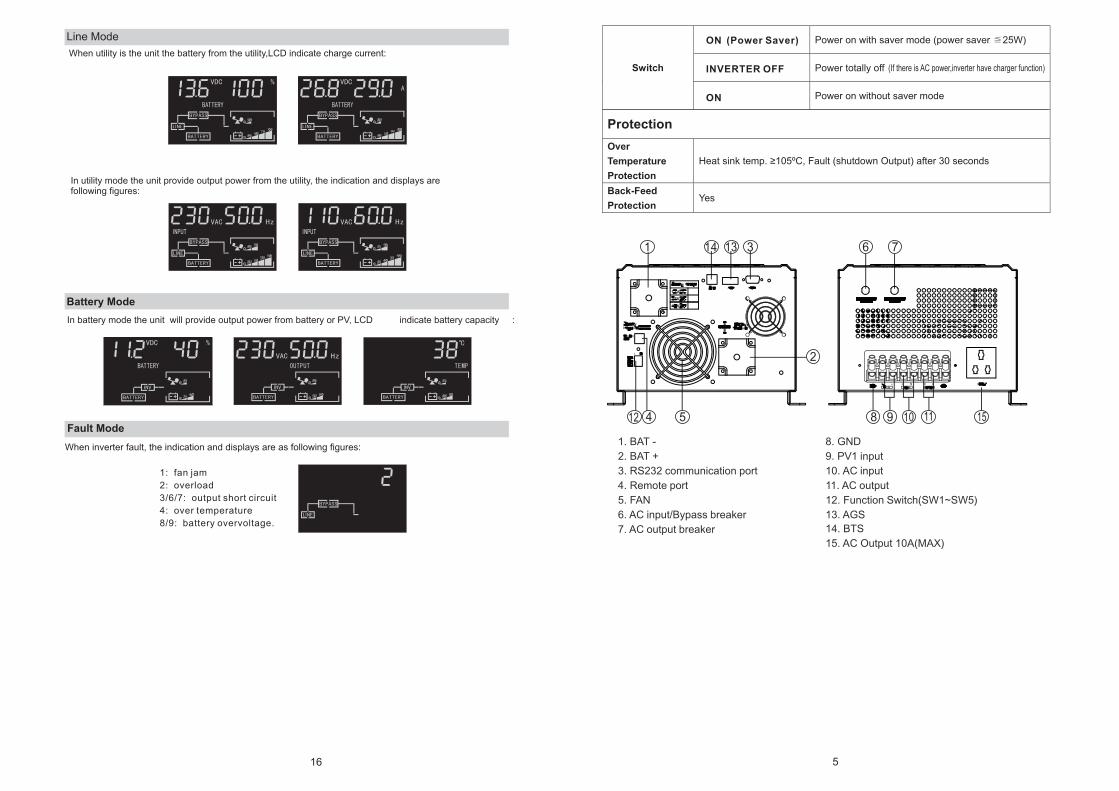
1. BAT -
2. BAT +
3. RS232 communication port
4. Remote port
5. FAN
6. AC input/Bypass breaker
7. AC output breaker
8. GND
9. PV1 input
10. AC input
11. AC output
12. Function Switch(SW1~SW5)
13. AGS
111098
6 7
2
4 512
1 31314
5
15
14. BTS
15. AC Output 10A(MAX)
ON Power Saver)(
INVERTER OFF
ON
16
Line Mode
When utility is the unit the battery from the utility,LCD indicate charge current:
In utility mode the unit provide output power from the utility, the indication and displays are following figures:
In battery mode the unit will provide output power from battery or PV, LCD : indicate battery capacity
6 15
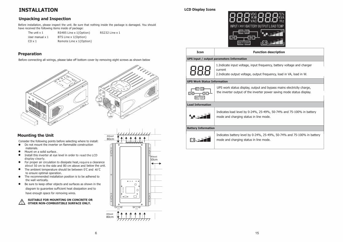
LCD Display Icons
Load Information
Battery Information
UPS Work Status Information
UPS input / output parameters Information
load
1.Indicate input voltage, input frequency, battery voltage and charger
current
2.Indicate output voltage, output frequency, load in VA, load in W.
UPS work status display, output and bypass mains electricity charge,
the inverter output of the inverter power saving mode status display.
307,9
153,9
257,60
477,0
238,5
253,55
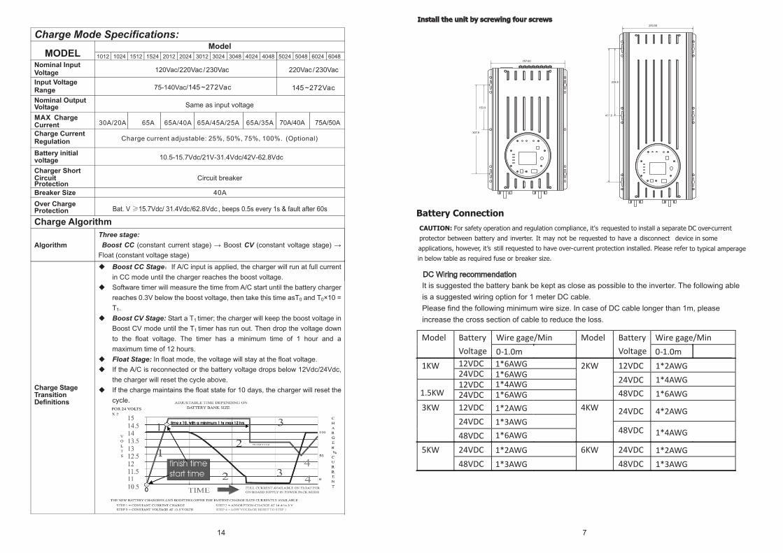
7
1*6AWG1*6AWG
1.5KW1*4AWG1*6AWG
1*2AWG
1*6AWG
1*2AWG
1*3AWG
1*3AWG
1*3AWG
1*2AWG
1*4AWG
4*2AWG
1*2AWG
1*6AWG
1*4AWG
14
120Vac/
75-140Vac/
1012 1024 1512 1524 2012 2024 3012 3024 3048 4024 4048 5048 6048 5024 6024
10.5-15.7Vdc/21V-31.4Vdc/42V-62.8Vdc
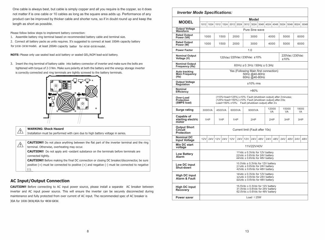
8
30A for 1KW-3KW,40A for 4KW-6KW.
13
120Vac/
1012 1024 1512 1524 2012 2024 3012 3024 3048 4024 4048 5048 6048 5024 6024
11V22V44V

6
9
6
12
120Vac
75Vac 2%
80Vac 2%
140Vac
2%
140Vrms/270Vrms
135Vac
265Vac
120Vac 1-1.5KW 30A/2-4KW 40A230Vac 1-3KW 30A/3-6K 40A
1012 1024 1512 1524 2012 2024 3012 3024 3048 4024 4048 5024 5048 6048 6024
220Vac/230Vac
145Vac 2%
155Vac 2%
272Vac
2%
2%
2%

PV CONNECTION
DC12V/24V 40A
18V~90V
12V/24V
13.7V/27.4V
14.3V/28.6V
10.5V/21V
40A
10 11
DC24V/48V
24V/48V
27.4V/54.8V
28.6V/57.2V
21V/42V