user operation and maintenance manual - elva-1€¦ · · 2014-03-10user operation and...
TRANSCRIPT
User Manual ELVA-1
Doppler sensor 94GHz 0
USER OPERATION AND MAINTENANCE
MANUAL
DOPPLER SENSOR 94GHz
Part No. DPR-94/100
1
st Edition
November 2012
www.ealva-1.com [email protected]
User Manual ELVA-1
Doppler sensor 94GHz 1
Table of Contents.
1. Introduction.
1.1 General Description.
2. Specifications.
2.1 Electrical.
2.2 Mechanical.
2.3 Block-diagram of Doppler sensor.
2.4 Transmitter.
2.5 Receiver.
2.6 Power supply
3. Installation.
3.1 Assembly procedure and put into operation
3.2 Output Power control.

User Manual ELVA-1
Doppler sensor 94GHz 2
1. INTRODUCTION.
This instruction manual contains information on installation and operation of the Doppler
sensor 94GHz.
1.1 General Description.
Doppler sensor DPR-94/100 is intended for measuring Doppler shift affect from different
targets at 94GHz frequency. The system is completed Cassegrain antennas 200 and 600mm
diameter.

User Manual ELVA-1
Doppler sensor 94GHz 3
2. SPECIFICATIONS.
2.1 Electrical Specifications. Transmitter
1. Output Frequency 94 GHz
2. Frequency Stability determined by reference
3. Output RF Power 100 mW
4. Output power regulation (VCVA) 0-60dB
5. Control current for VCVA 0-65mA
6. Input Reference Frequency 7.23GHz
7. Input power of reference Frequency 20mW
8. Waveguide WR-10
9. Flange UG-387/U
10. Reference Frequency connector SMA (f)
11. Control input for attenuator connector SMA(f)
12. Power connector DB-9
13. DC Power +12 VDC@390mA
-12 VDC@10mA
+24 VDC@310mA
14. AC power 100-240V AC (External unit)
Receiver
1. Input Frequency 94 GHz
2. LO frequency 87.77 GHz
3. Frequency Stability 1*10-6 1/°C
4. Input RF Power (max) 0 dBm
5. Noise figure 7.6 dB
6. Total gain RF-IF 65 dB
7. IQ Phase balance +/-1 deg
8. I and Q IF Frequency range 0 to 10kHz
9. Output Reference Frequency 7.23 GHz
10. Output power of reference Frequency 30 mW
11. Waveguide WR-10
12. Flange UG-387/U
13. Reference Frequency connector SMA (f)
14. IQ connectors SMA(f)
15. Power connector DB-9
16. DC Power +12 VDC@900mA
-12 VDC@55mA
+24 VDC@110mA
+24 VDC@500mA (thermostat)
17. AC power 100-240V AC (External unit)
2.2 Mechanical Specifications. Transmitter
1. Size 70x145x205 mm;
2. Weight 1.9 kg.
Receiver
3. Size 70x185x360 mm;
4. Weight 4.1kg.

User Manual ELVA-1
Doppler sensor 94GHz 4
2.3 Block-diagram of the Doppler Sensor.
Picture No1. Block-Diagram of the Doppler sensor.
7.2 GHz Power
Amplifier
Balanced
Mixer
Frequency
Multiplier
x13
IQ Outputs
To Antenna
Iso
lato
r Bandpass
Filter
94 GHz
From Antenna
Receiver Module
ILA
LNA
7.2 GHz
IQ Mixer
OA OA
VC
VA
DRO
7.23 GHz
7.2 GHz Power
Amplifier
with divider
Frequency
Multiplier
x12 Iso
lato
r Bandpass
Filter
86.7 GHz
Transmitter Module
Attenuator control

User Manual ELVA-1
Doppler sensor 94GHz 5
2. 4 Transmitter.
Disposition of the connectors on the front panel of the transmitter is the following:
Picture No2. Front panel of the Transmitter.
Disposition of connectors on the rear panel of the transmitter is the following:
Picture No3. Rear panel of the Transmitter.
1. RF output, WR-10, UG-387/U-M;
2. Power connector, DB-9;
3. Input for reference frequency 7.23GHz@20mW from receiver unit, SMA(f)
4. Input control for attenuator, 0 …+60mA, SMA(f);
1
2 3 4

User Manual ELVA-1
Doppler sensor 94GHz 6
2. 5 Receiver
Disposition of connectors on the front panel of the Receiver is the following:
Picture No4. Front panel of the Receiver.
Disposition of connectors on the rear panel of the Receiver is the following:
Picture No5. Rear panel of the Receiver.
5. RF input, WR-10, UG-387/U-M
6. Output “I”, SMA(f);
7. Output reference frequency 7.23GHz@30mW, SMA(f);
8. Output “Q” SMA(f);
9. Power connector, DB-9;
5
6 7 8 9
User Manual ELVA-1
Doppler sensor 94GHz 7
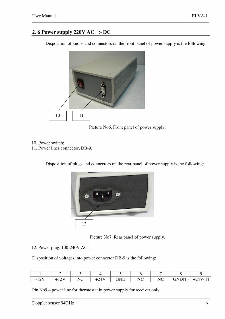
2. 6 Power supply 220V AC => DC
Disposition of knobs and connectors on the front panel of power supply is the following:
Picture No6. Front panel of power supply.
10. Power switch;
11. Power lines connector, DB-9.
Disposition of plugs and connectors on the rear panel of power supply is the following:
Picture No7. Rear panel of power supply.
12. Power plug. 100-240V AC;
Disposition of voltages into power connector DB-9 is the following:
1 2 3 4 5 6 7 8 9
-12V +12V NC +24V GND NC NC GND(T) +24V(Т)
Pin No9 – power line for thermostat in power supply for receiver only
10 11
12
User Manual ELVA-1
Doppler sensor 94GHz 8
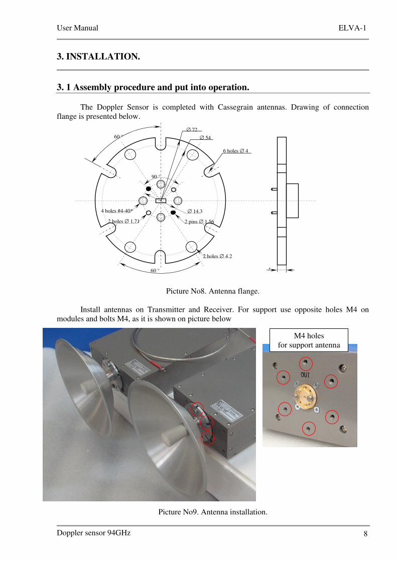
3. INSTALLATION.
3. 1 Assembly procedure and put into operation.
The Doppler Sensor is completed with Cassegrain antennas. Drawing of connection
flange is presented below.
Picture No8. Antenna flange.
Install antennas on Transmitter and Receiver. For support use opposite holes M4 on
modules and bolts M4, as it is shown on picture below
Picture No9. Antenna installation.
4
6 holes ∅ 4
4 holes #4-40*
∅ 72
∅ 54 60 °
60 °
∅ 14.3
2 holes ∅ 1.71 2 pins ∅ 1.56
2 holes ∅ 4.2
90 °
M4 holes
for support antenna

User Manual ELVA-1
Doppler sensor 94GHz 9
After installation of antennas connect output reference frequency 7.23GHz (7) with input
reference frequency on the Transmitter (3) by SMA-SMA coaxial cable. Cable is applied.
Connect power supplies with modules according to marking:
ATTENTION!
DO NOT USE TENSMITTER POWER SUPPLY WITH RECEIVER MODULE!
Power cables DB-9 – DB-9 are applied.
Connect power supplies to primary line 100-240V AC.
Connect IQ outputs to data acquisition system.
Switch ON power supplies by power switch (10).
The Doppler sensor is ready for operation.
3. 2 Output power control.
There is built-in Voltage Controlled Variable Attenuator (VCVA). It is controlled by bias
current. If user wants to use voltage supply, protection resistor must be installed. An example of
switching is presented below:
Table attenuation vs bias is presented below
Attenuation, dB -3 -6 -10 -20 -30 -40 -50 -60
Bias, mA 1,42 3,03 5,50 12,95 23,6 33,5 45,5 63,1
ATTENTION!
DO NOT APPLY DIRECTLY VOLTAGE SUPPLY DIRECTLY TO CONTROL INPUT FOR
VCVA!
R=100 Ohm (min)
VCVA Ucontr = 0-+10V
Ibias=Ucon/R