user manual vs-881
TRANSCRIPT
User Manual
VS-881Read this guide thoroughly and follow the installation and operation proce-dures carefully in order to prevent any damage to the units and/or any de-vices that connect to them.
This package contains:
� 1 8 Port Video Switch� 1 Infrared Remote Control Handset� 1 Infrared Receiver (with 1.8m attached cable)� 1 Video Cable (1.2m)� 1 Power Adapter� 1 User Manual� 1 Quick Start Guide
© Copyright 2000 ATEN®
International Co., Ltd.Manual Part No. PAPE - 1213-100Printed in Taiwan 12/2002
All brand names and trademarks are the registered property of theirrespective owners.
2002-12-13

NOTE: This equipment has been tested and foundto comply with the limits for a Class B digital devicepursuant to Subpart J of Part 15 of FCC Rules. Theselimits are designed to provide reasonable protectionagainst harmful interference in a residentialinstallation. This equipment generates, uses and canradiate radio frequency energy and, if not installedand used in accordance with the instructions, maycause harmful interference to radio communications.However, there is no guarantee that interference willnot occur in a particular installation. If this equipmentdoes cause harmful interference to radio or televisionreception, which can be determined by turning theequipment off and on, the user is encouraged to tryto correct the interference by one or more of thefollowing measures:
� Reorient or relocate the receiving antenna.
� Increase the separation between the equipmentand reciever.
� Connect the equipment into an outlet on a circuitdifferent from that to which the receiver isconnected.
� Consult the dealer or an experiencedradio/television technician for help.
2002-12-13
OverviewThe VS-881 Video Switch is a modern control unit thatallows you to conveniently display the video output ofeight separate computer systems on a single monitor, orvia a multimedia projector - thereby eliminating theunnecessary expense of purchasing a separate monitorfor each computer. The VS-881 is perfect for corporatepresentations, company briefings and institutionallearning centers.
The VS-881 improves on previous video switch modelswith enhanced features that include a freely accessibleconcentric-hub design; easy computer selection via pushbuttons; intelligent infrared (IR) remote control; andelectronic switching technology, rather than mechanicalswitching, for reliability and durability.
The VS-881 also saves on the space that additionalmonitors take up, as well as the extra power costs, andeliminates the inconvenience and wasted effort involvedin constantly moving around from one computer toanother.
- 1 -
2002-12-13

Features
� Displays the video output of eight separate computerson a single monitor or projector
� New modern concentric design with logical connectorlayout for quick and easy access
� Fast and convenient computer selection via pushbuttons or infrared (IR) remote control
� External IR Receiver (1.8m) for maximum efficiencyand convenience
� Extra-thin IR handset allows easy storage in themother unit
� Electronic Switching for greater reliability and durability
� High resolution video - up to 2048 x 1536; DDC;DDC2; DDC2B
� Supports, VGA, SVGA, XGA and multisync monitors
� Easy installation - no software required - noconfiguration necessary
- 2 -
2002-12-13

System Requirements
� One VGA, SVGA, XGA, or Multisync compatibleanalog monitor, with a standard PC high density cablehaving a 15 pin HDB type male connector
� One VGA, SVGA, XGA,or Multisync analog video cardhaving a standard PC 15 pin HDB type femaleconnector per computer.
� A video cable with one male and one female HDB-15connector at each end for each computer you will beinstalling.
Note: One (1) video cable is supplied with this unit.
- 3 -
2002-12-13

Front View
1. IR Reciever PortThe external IR Receiver has an attached cable thatallows it to be placed anywhere up to 1.8m from theswitch, The cable from the external IR Receiver plugsin here.
2. Monitor PortThe cable from the monitor or digital projector plugs inhere.
3. Power JackThe AC Power Adapter cable plugs in here.
- 4 -
1 2 3
2002-12-13

Rear View
1. Video PortsThe cables that connect to the computer video portsplug in here.
There are eight video ports distributed around theVS-881’s circumference.
- 5 -
1 1
2002-12-13

Top View
1. Port LEDs� A LED lights ORANGE to indicate the computer
connected to to its corresponding port is Online.
� The LED changes to GREEN to indicate the computerconnected to to its corresponding port is the one that iscurrently selected.
� The LED goes out when the computer connected to to itscorresponding port is in Standby mode.
2. Port Down SwitchPress this button to switch the video focus to thecomputer previous to the current one.
3. VGA Display On / OffPowers the unit’s VGA display ON and OFF.
4. Port Up Switch Press this button to switch the video focus to thecomputer subsequent to the current one.
- 6 -
1
2
3
4
2002-12-13

IR Remote Control Unit
1. VGA Display ON / OFFPowers the unit’s VGA display ON and OFF.
2. Port Up / Port DownThese buttons function in a similar manner to the PortUp / Port Down buttons on the main unit. Press thesebuttons to switch the video focus to the NEXTorPREVIOUS computer on the installation.
3. Port SelectionThe numbers correspond to the video ports on themain unit. Press a button (1 to 8) to switch the videofocus to the computer connected to to itscorresponding port.
Note: The VS-881’s remote control handset comespackaged in protective plastic film. Pleaseremove this film before operating it with theVS-881 main unit.
- 7 -
1
1
2
3
2002-12-13
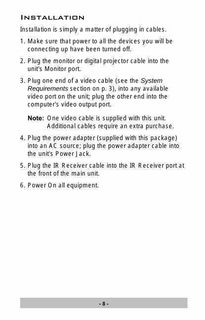
InstallationInstallation is simply a matter of plugging in cables.
1. Make sure that power to all the devices you will beconnecting up have been turned off.
2. Plug the monitor or digital projector cable into theunit’s Monitor port.
3. Plug one end of a video cable (see the SystemRequirements section on p. 3), into any availablevideo port on the unit; plug the other end into thecomputer’s video output port.
Note: One video cable is supplied with this unit.Additional cables require an extra purchase.
4. Plug the power adapter (supplied with this package)into an AC source; plug the power adapter cable intothe unit’s Power Jack.
5. Plug the IR Receiver cable into the IR Receiver port atthe front of the main unit.
6. Power On all equipment.
- 8 -
2002-12-13
- 9 -
2002-12-13
Port SelectionManual Port Up / Port Down
Use the Port Up and Port Down buttons, located on thetop of the VS-881 unit, to cycle the video focus to theport you want.
A Port LED changes from ORANGE to GREEN toindicate that the computer connected to its correspondingport has the video focus.
IR Port Up / Port Down
The video focus can also be cycled among thecomputers using the Port Up and Port Down buttons ofthe IR Remote Control Unit (see p. 7).
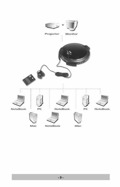
Note: The IR Remote Control Unit is used in conjunctionwith the external IR Receiver (see the diagram onp. 9).
- 10 -
2002-12-13

IR Direct Port Selection
Instead of cycling among the individual computersone-by-one, a computer can be directly selected bypushing the button on the Remote Control Unit thatcorresponds to its port number (1-8) on the main unit.
The selected port’s LED changes from ORANGE toGREEN to indicate that the computer connected to itscorresponding port has the video focus.
Note: For optimum performance make sure that there is a clear line-of-site between the handset and the receiver.
- 11 -
2002-12-13

Specifications
Function Specification
Connectors Video In 8 HDB-15 Male
Video Out 1 HDB-15 Female
Power In 1 Power Adapter Jack
IR 1 Earphone Jack
LEDs 8 Online / Selected (Orange / Green)
1 VGA Display ON/OFF (Blue)
Port Selection Push Button Switches / IR Remote Control
Video Resolution 2048 x 1536
Power Consumption AC 9V, 4.5W
Operating Temperature 0 ~ 50oC
Storage Temperature -20 ~ 60oC
Humidity 0 ~ 80% RH Non condensing
Housing Plastic
Weight 0.45 Kg
Dimensions (L x W x H) 17 x 19 x 4.5 cm
- 12 -
2002-12-13

Limited WarrantyIN NO EVENT SHALL THE DIRECT VENDOR’SLIABILITY FOR DIRECT, INDIRECT, SPECIAL,INCIDENTAL, OR CONSEQUENTIAL DAMAGESRESULTING FROM THE USE OF THE PRODUCT,DISK, OR ITS DOCUMENTATION EXCEED THEPRICE PAID FOR THE PRODUCT.
The direct vendor makes no warranty or representation,expressed, implied, or statutory with respect to thecontents or use of this documentation, and especiallydisclaims its quality, performance, merchantability, orfitness for any particular purpose.
The direct vendor also reserves the right to revise orupdate the device or documentation without obligation tonotify any individual or entity of such revisions, or update.For further inquiries, please contact your direct vendor.
- 13 -
2002-12-13

Notes:
- 14 -
2002-12-13