user manual pm50 pm50d pm50d20 - mpb srl
TRANSCRIPT
MPB S.r.l. Tel +39 0641200744
Via Giacomo Peroni 400/402 Fax +39 0641200653
00131 ROMA (RM) [email protected]
www.gruppompb.com
User Manual
PM50
PM50D
PM50D20
Personal Protection
Equipment (PPE)
Updated to Software Version:PM50 Manager V1.14
Updated to Firmware Version:PM50 V1.10

SAFETY NOTES
Read carefully before using the product
MPB works to provide to its customers the best safety conditions available com-plying with the current safety standards. The instrumentation described in thismanual has been produced, tested and left the factory in conditions that fullycomply the European standards. To maintain it in safe conditions and ensurethe correct use, these general instructions must be fully understood and appliedbefore using the product. This product is designed for industrial environmentand laboratories and should be used by skilled sta� only. MPB disclaims respon-sibility for a di�erent use of the device.
II - USER MANUAL_V2.4-PM50 EN

Declaration of Conformity
(in accordance with the Directives: EMC 89/336/EEC and Low Voltage 73/23/EEC)
This is to certify that the product: PM50 e PM50D
(Personal protection equipment)
complies with the following European Standards:
Safety: CEI EN 61010-1 (2001)
EMC: EN 61326-1 (2007)
This product complies with the requirements of the Low Voltage Directive
2006/95/CE, and with the EMC Directive 2004/108/CE.
MPB S.r.l.
USER MANUAL_V2.4-PM50 EN - III

IV - USER MANUAL_V2.4-PM50 EN
Contents
1 General information 1
1.1 Introduction . . . . . . . . . . . . . . . . . . . . . . . . . . . . . . 1
1.2 Description . . . . . . . . . . . . . . . . . . . . . . . . . . . . . . 2
1.3 Composition . . . . . . . . . . . . . . . . . . . . . . . . . . . . . . 2
1.4 Optional Kit . . . . . . . . . . . . . . . . . . . . . . . . . . . . . . 2
1.5 Front PM50 . . . . . . . . . . . . . . . . . . . . . . . . . . . . . . 2
1.6 PM50D / PM50D-20 Front . . . . . . . . . . . . . . . . . . . . . . 3
1.7 Technical Speci�cations . . . . . . . . . . . . . . . . . . . . . . . . 4
1.8 Accessories . . . . . . . . . . . . . . . . . . . . . . . . . . . . . . . 6
2 Principle of operation 7
2.1 PM50 . . . . . . . . . . . . . . . . . . . . . . . . . . . . . . . . . 7
2.2 PM50D / PM50D-20 . . . . . . . . . . . . . . . . . . . . . . . . . 8
3 Use and Operations on PM50D / PM50D-20 9
3.1 Turning On . . . . . . . . . . . . . . . . . . . . . . . . . . . . . . 9
3.2 Menu in PM50D / PM50D-20 . . . . . . . . . . . . . . . . . . . . 11
3.2.1 Alarm . . . . . . . . . . . . . . . . . . . . . . . . . . . . . 11
3.2.2 Threshold . . . . . . . . . . . . . . . . . . . . . . . . . . . 12
3.2.3 Line2 . . . . . . . . . . . . . . . . . . . . . . . . . . . . . . 14
3.2.4 Unit . . . . . . . . . . . . . . . . . . . . . . . . . . . . . . 15
3.2.5 AutoOFF . . . . . . . . . . . . . . . . . . . . . . . . . . . 16
3.2.6 Mode . . . . . . . . . . . . . . . . . . . . . . . . . . . . . . 17
3.2.7 Logger . . . . . . . . . . . . . . . . . . . . . . . . . . . . . 19
3.2.8 LOG Time . . . . . . . . . . . . . . . . . . . . . . . . . . . 19
3.2.9 Contrast . . . . . . . . . . . . . . . . . . . . . . . . . . . . 21
3.2.10 Date & Time . . . . . . . . . . . . . . . . . . . . . . . . . 22
3.3 DATA LOGGER modality . . . . . . . . . . . . . . . . . . . . . . 24
3.4 REAL TIME modality . . . . . . . . . . . . . . . . . . . . . . . . 25
4 Use and Operations on PM50 27
V

CONTENTS
5 PC Software PM50 Manager 295.1 Installation . . . . . . . . . . . . . . . . . . . . . . . . . . . . . . 295.2 Working with PM50, PM50D e PM50D-20 . . . . . . . . . . . . . 325.3 First Connection . . . . . . . . . . . . . . . . . . . . . . . . . . . 345.4 Clock Sync . . . . . . . . . . . . . . . . . . . . . . . . . . . . . . 365.5 Logger Setup . . . . . . . . . . . . . . . . . . . . . . . . . . . . . 365.6 Alarm Setup . . . . . . . . . . . . . . . . . . . . . . . . . . . . . . 375.7 Data Download . . . . . . . . . . . . . . . . . . . . . . . . . . . . 385.8 Data Folder . . . . . . . . . . . . . . . . . . . . . . . . . . . . . . 415.9 Start new Log . . . . . . . . . . . . . . . . . . . . . . . . . . . . . 43
6 Firmware PM50D / PM50D-20 456.1 Download and install the Updater . . . . . . . . . . . . . . . . . . 456.2 Firmware Update . . . . . . . . . . . . . . . . . . . . . . . . . . . 46
A Technical Notes 51A.1 Troubleshooting in Driver installation . . . . . . . . . . . . . . . . 51
Elenco delle �gure 56
Elenco delle tabelle 57
VI - USER MANUAL_V2.4-PM50 EN
Chapter 1
General information
(a) PM50 (b) PM50D / PM50D-20
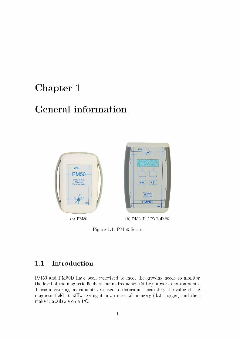
Figure 1.1: PM50 Series
1.1 Introduction
PM50 and PM50D have been conceived to meet the growing needs to monitorthe level of the magnetic �elds at mains frequency (50Hz) in work environments.These measuring instruments are used to determine accurately the value of themagnetic �eld at 50Hz storing it in an internal memory (data logger) and thenmake it available on a PC.
1

1. General information
1.2 Description
PM50 (Figure 1.1(a)) is a small instrument for personal measurement that canbe tied around the neck or wrist with the appropriate accessories. The �PM50D�and �PM50D-20� (Figure 1.1(b)) version is slightly larger and has a display anda keyboard
1.3 Composition
Both devices come with a USB cable and a PC Software �PM50 Manager�
1.4 Optional Kit
Anchor Kit, and only for PM50D & PM50D-20 rechargeable batteries with charger.
1.5 Front PM50
In Figure 1.2 is represented the front panel of PM50:
Red / Green Led
Micro USB connector
Figure 1.2: PM50 front
2 - USER MANUAL_V2.4-PM50 EN

1. General information
1.6 PM50D / PM50D-20 Front
In Figure 1.3 is represented the front panel of PM50-D and PM50-D-20 with thedisplaying interface (display) and the control part (keyboard).
Micro USB connector
Red / Green Led
Display
Keyboard
Batteries Space
Figure 1.3: PM50D / PM50D-20 front
USER MANUAL_V2.4-PM50 EN - 3

1. General information
1.7 Technical Speci�cations
Speci�cations are subject to change without notice.
4 - USER MANUAL_V2.4-PM50 EN

1. General information
PM50 PM50D PM50D20
Type of sensor Triaxial magneto-resistive* Triaxial magneto-resistive* Triaxial windings
Frequency range @Full band @Full band @Fullband
Within 1dB 38Hz -> 10kHz 38Hz -> 10kHz 48Hz -> 500kHz
Within 3dB 25Hz -> 30kHz 25Hz -> 30kHz 35Hz -> 5kHz
Level Range 300 nT to 1 mT 300 nT to 1 mT 10 µT to 20 mT
Resolution 10 nT 10 nT 10 µT
Overload 2 mT 2 mT 22 mT
Dynamic 70 dB 70 dB 66 dB
Error of measurement 40− 1000 Hz / 1− 300 µT 40− 1000 Hz / 1− 300 µT 45− 500 Hz / 0, 1− 20 mT
Linearity 1.2 dB 1.2 dB 1.2 dB
Absolute error 1.6 dB 1.6 dB 1.6 dB
Unit of measurement µT; A/m µT; A/m; mT; kA/m;
User de�nedmeasurement mode
Selective at 50Hz; 50Hz +harmonics; wide band
Selective at 50Hz; 50Hz +harmonics; Selective at60Hz; 60Hz + harmonics;Notch at 50Hz and 60Hz;
wide band
Selective at 50Hz; 50Hz +harmonics; Selective at60Hz; 60Hz + harmonics;Notch at 50Hz and 60Hz;
wide band
Data logger
Max recording time 24 h 168 h 168 h
Acquisition time 5. . . 60 sec 5. . . 30sec (24h)30sec (168h)
5. . . 60 sec
Display n.a. LCD 2 lines x 16 charactersbacklit
LCD 2 lines x 16 charactersbacklit
Multifunction ledGreen led � status of the
measureGreen led � status of the
measureGreen led � status of the
measure
Red led � alarm thresholdexceeded
Red led � alarm thresholdexceeded
Red led � alarm thresholdexceeded
I/O Interface USB USB USB
Acoustic alarmProgrammable threshold
by SW PCPreset thresholds from 1µT
to 500µT, step 1µTPreset thresholds from0.1mT to 20.0mT, step
0.1mT
Auto Shutdown n.a. 20min; 60min; deactivated 20min; 60min; deactivated
Date and Watch Adjustable via PC SW Adjustable by the operator Adjustable by the operator
Reference standards 2013/35/EC Directive 2013/35/EC Directive 2013/35/EC Directive
Operating temperature −10◦C to 40◦C −10◦C to 40◦C −10◦C to 40◦C
Sensor position Showed on the case Showed on the case Showed on the case
Power rechargeable Li-Ion (USBpowered)
2 Alkaline AA or 2rechargeable Ni-MH
2 Alkaline AA or 2rechargeable Ni-MH
Battery life 48 h @ Cadence > 30sec Alkaline > 80h; Ni-MH1900mA/h > 168h
Alkaline > 80h; Ni-MH1900mA/h > 168h
Dimensions 76 x 44 x 18 mm 118 x 79 x 25 mm 118 x 79 x 25 mm
Weight 26 gr 125 gr 125 gr
* Operation ensured in presence of static magnetic �elds below 100µT
Table 1.1: Technical speci�cations PM50-Series
USER MANUAL_V2.4-PM50 EN - 5

1. General information
1.8 Accessories
AccessoriesUSB interface cable
PC software for data download and programming
Calibration certi�cate Standard
Anchor Kit Upper limbs, trunk and waist Waist and table / tripod
Table 1.2: PM50 Series Accessories
6 - USER MANUAL_V2.4-PM50 EN

Chapter 2
Principle of operation
2.1 PM50
The block diagram below in Figure 2.1 depicts the personal protection devicePM50:
Triaxial
SensorADC
Digital Part
CPU
RTC
MEM
USB
Figure 2.1: block diagram PM50
The triaxial sensor measures the magnetic �eld then ,after an appropriateampli�cation, it sends the value to the analog-digital convertor (ADC) that makesit available to the CPU. This signal is then stored in the MEM with the timinggiven by the RTC. The USB port s used to download data to a PC.
7

2. Principle of operation
2.2 PM50D / PM50D-20
PM50D operating principle is very similar to the PM50's, following block dia-gram in Figure 2.2. In addition to the components of PM50 the big brother
Triaxial
SensorADC
Parte Digitale
CPU
RSP
DSP
Display
Keyboard
USB
Figure 2.2: block diagram PM50-D e PM50-D-20
is enriched by a display, which allows the visualization of the �eld values, and akeyboard used to program it.
8 - USER MANUAL_V2.4-PM50 EN

Chapter 3
Use and Operations on PM50D /PM50D-20
3.1 Turning On
Release Date
Release n◦
ON/OFF
PM50D
x.xx xx/xx
Figure 3.1: turned on PM50D / PM50D-20
9

3. Use and Operations on PM50D / PM50D-20
The PM50D / PM50D-20 doesn't need external power; It works with 2 bat-
teries AA of 1,5V stocked on the devices back.By brie�y pressing the power button on the PM50D keyboard you
will start the machine, for the shutdown hold the same button for4 seconds. As soon as the instrument is turned on, the display willshow the following screen representing the release of the FW and thedate of issue, as in Figure 3.1.
After a few seconds will appear a screen (Figure 3.2) showing themeasure in the same format used before the last shutdown. The stateled starts to �ash the green light, to point that the device is ready formeasuring. On the device display will be showed the measurement ofthe magnetic �eld, for the PM50D in µT or A
m , for the PM50D-20 inmT or kA
m , depends on device settings. In detail, the �rst row showsthe measured isotropic �eld, while the second row is user selectable,as showed in Chapter 3.2.3.
axis measure
Isotropic �eld
00.0uT
0.00 0.00 0.00
Figure 3.2: measuring display
10 - USER MANUAL_V2.4-PM50 EN
3. Use and Operations on PM50D / PM50D-20
3.2 Menu in PM50D / PM50D-20
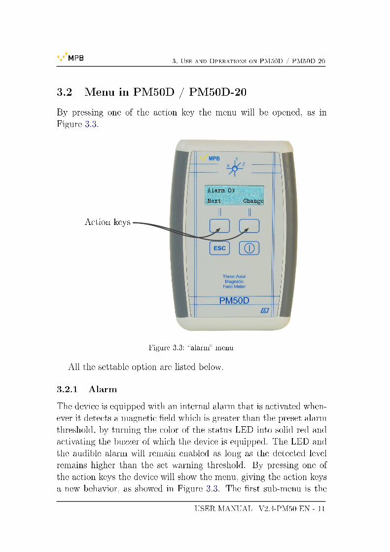
By pressing one of the action key the menu will be opened, as inFigure 3.3.
Action keys
Alarm ON
Next Change
Figure 3.3: �alarm� menu
All the settable option are listed below.
3.2.1 Alarm
The device is equipped with an internal alarm that is activated when-ever it detects a magnetic �eld which is greater than the preset alarmthreshold, by turning the color of the status LED into solid red andactivating the buzzer of which the device is equipped. The LED andthe audible alarm will remain enabled as long as the detected levelremains higher than the set warning threshold. By pressing one ofthe action keys the device will show the menu, giving the action keysa new behavior, as showed in Figure 3.3. The �rst sub-menu is the
USER MANUAL_V2.4-PM50 EN - 11
3. Use and Operations on PM50D / PM50D-20
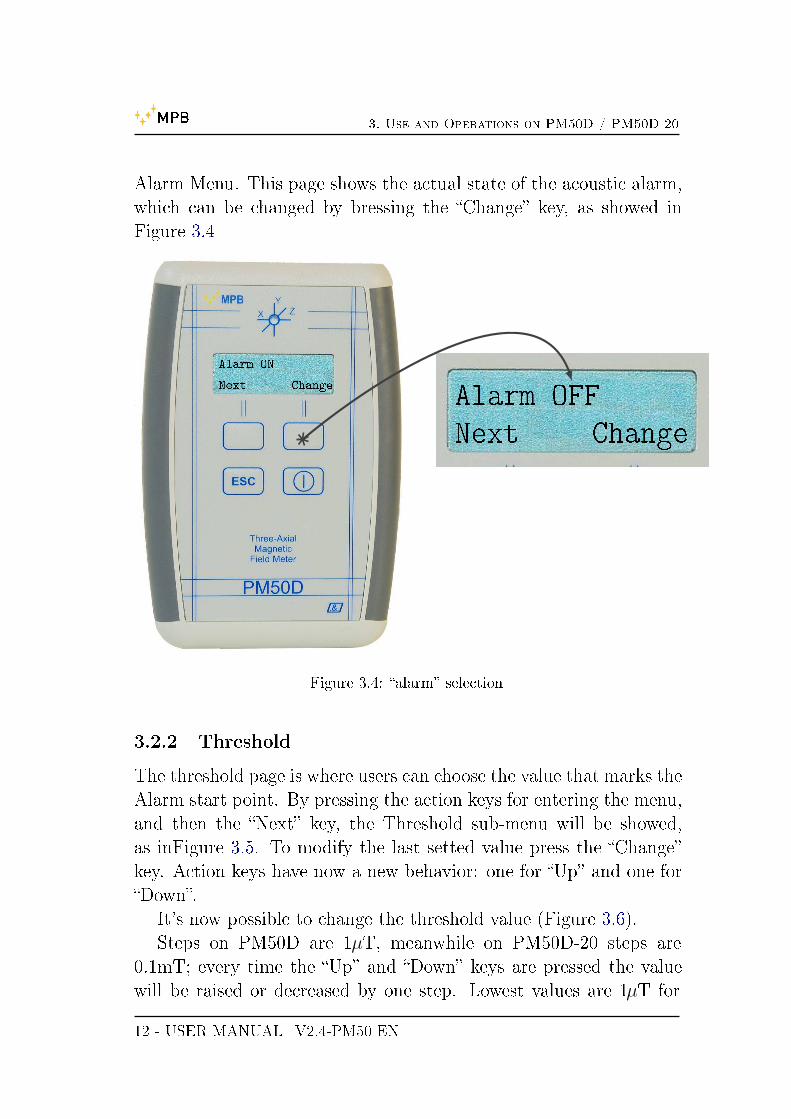
Alarm Menu. This page shows the actual state of the acoustic alarm,which can be changed by bressing the �Change� key, as showed inFigure 3.4
Alarm ON
Next Change
Alarm OFF
Next Change
Figure 3.4: �alarm� selection
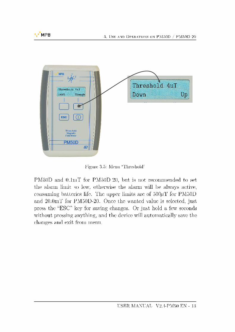
3.2.2 Threshold
The threshold page is where users can choose the value that marks theAlarm start point. By pressing the action keys for entering the menu,and then the �Next� key, the Threshold sub-menu will be showed,as inFigure 3.5. To modify the last setted value press the �Change�key. Action keys have now a new behavior: one for �Up� and one for�Down�.
It's now possible to change the threshold value (Figure 3.6).Steps on PM50D are 1µT, meanwhile on PM50D-20 steps are
0.1mT; every time the �Up� and �Down� keys are pressed the valuewill be raised or decreased by one step. Lowest values are 1µT for
12 - USER MANUAL_V2.4-PM50 EN
3. Use and Operations on PM50D / PM50D-20
Threshold 4uT
Next Change
Threshold 4uT
Down Up
Figure 3.5: Menu �Threshold�
PM50D and 0.1mT for PM50D-20, but is not recommended to setthe alarm limit so low, otherwise the alarm will be always active,consuming batteries life. The upper limits are of 500µT for PM50Dand 20.0mT for PM50D-20. Once the wanted value is selected, justpress the �ESC� key for saving changes. Or just hold a few secondswithout pressing anything, and the device will automatically save thechanges and exit from menu.
USER MANUAL_V2.4-PM50 EN - 13

3. Use and Operations on PM50D / PM50D-20
Threshold 4uT
Down Up
Threshold 5uT
Down Up
Threshold 3uT
Down Up
Figure 3.6: Con�guring �Threshold�
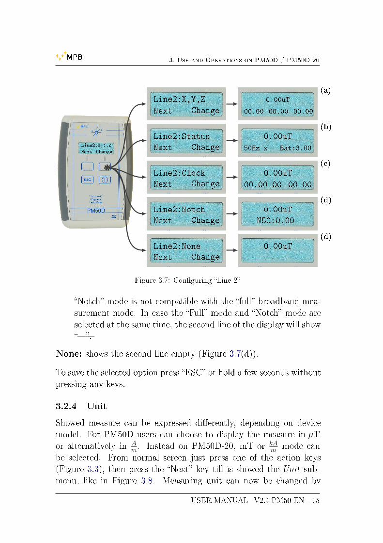
3.2.3 Line2
The second line of the display in working mode is customizable, anddepends on user preference: by pressing action keys will be showedthe main menu (Figure 3.3), then press the �Next� key till the Line2sub-menu is visible, like in Figure 3.7. It's now possible to changedisplay modality:
X,Y,Z: shows the detected magnetic �eld along x, y and z axes (Fig-ure 3.7(a)).
Status: shows the setted �lter, the current measuring axis and thecharge batteries level (Figure 3.7(b)).
Clock: shows the current time (hh.mm.ss) and date (DD.MM) as inFigure 3.7(c).
Notch: shows the contribution of the �eld of the whole band exceptfor components due to modalty through the �Mode� menu. The
14 - USER MANUAL_V2.4-PM50 EN
3. Use and Operations on PM50D / PM50D-20
Line2:X,Y,Z
Next Change
Line2:X,Y,Z
Next Change
Line2:Status
Next Change
Line2:Clock
Next Change
Line2:Notch
Next Change
Line2:None
Next Change
0.00uT
00.00 00.00 00.00
(a)
0.00uT
50Hz x Bat:3.00
(b)
0.00uT
00.00.00 00.00
(c)
0.00uT
N50:0.00
(d)
0.00uT(d)
Figure 3.7: Con�guring �Line 2�
�Notch� mode is not compatible with the �full� broadband mea-surement mode. In case the �Full� mode and �Notch� mode areselected at the same time, the second line of the display will show���.
None: shows the second line empty (Figure 3.7(d)).
To save the selected option press �ESC� or hold a few seconds withoutpressing any keys.
3.2.4 Unit
Showed measure can be expressed di�erently, depending on devicemodel. For PM50D users can choose to display the measure in µTor alternatively in A
m . Instead on PM50D-20, mT or kAm mode can
be selected. From normal screen just press one of the action keys(Figure 3.3), then press the �Next� key till is showed the Unit sub-menu, like in Figure 3.8. Measuring unit can now be changed by
USER MANUAL_V2.4-PM50 EN - 15

3. Use and Operations on PM50D / PM50D-20
pressing �Change� key. As usual to save all changes just press �ESC�or hold a while without pressing anything.
Unit: uT
Next Change
Unit: A/m
Next Change
Figure 3.8: Sub-Menu �Unit�
3.2.5 AutoOFF
It's possible to choose if the device has to turn o� automatically aftertwo �xed time period: 20 minutes or 60 minutes. Otherwise user canchoose no auto shut down at all. From normal screen just press one ofthe action keys (Figure 3.3), then press the �Next� key till is showedthe AutoOFF sub-menu, like in Figure 3.9. By pressing the �Change�key are selectable:
Disabled: Auto shutdown is disabled, and the device can be turnedo� only by the operator (Figure 3.9).
20 min: The device will be in working mode for just 20 minutes, thenit will automatically turned o� (Figure 3.9(a)).
16 - USER MANUAL_V2.4-PM50 EN

3. Use and Operations on PM50D / PM50D-20
AutoOFF:Disabled
Next Change
AutoOFF: 20min
Next Change
(a)
AutoOFF: 60min
Next Change
(b)
Figure 3.9: Sub-Menu �AutoO��
60 min: The device will be in working mode for just 60 minutes, thenit will automatically turned o� (Figure 3.9(b)).
For saving the selected option press �ESC� or hold a few secondswithout pressing any keys.
3.2.6 Mode
Device gives the possibilities to choose the �lter modality among a50Hz �lter, 50Hz plus Harmonic frequencies and a Full Band �lter.From normal screen just press one of the action keys (Figure 3.3),then press the �Next� key till is showed the Mode sub-menu, like inFigure 3.10. Now by pressing the �Change� key there will be thesepossibilities:
USER MANUAL_V2.4-PM50 EN - 17

3. Use and Operations on PM50D / PM50D-20
Mode:Only 50Hz
Next Change
Mode:50Hz+Harm
Next Change
(a)
Mode:Only 60Hz
Next Change
(b)
Mode:60Hz+Harm
Next Change
(c)
Mode:FullBand
Next Change
(d)
Figure 3.10: Sub-Menu �Mode�
Only 50Hz: the returned measurement depends only on 50Hz fre-quency component (Figure 3.10).
50Hz+Harm: the returned measurement depends on 50Hz frequencyand all the relative Harmonics components, so that the value isthe result of quadratic sum of signals (Figure 3.10(a)).
Only 60Hz: the returned measurement depends only on 60Hz fre-quency component (Figure 3.10(b)).
60Hz+Harm: the returned measurement depends on 60Hz frequencyand all the relative Harmonics components, so that the value is
18 - USER MANUAL_V2.4-PM50 EN

3. Use and Operations on PM50D / PM50D-20
the result of quadratic sum of signals(Figure 3.10(c)).
Full Band: the returned measurement depends on all existing har-monics presents inside the device range of work (Figure 3.10(b)).
For save the selected option press �ESC� or hold a few seconds withoutpressing any keys.
3.2.7 Logger
This device series, besides showing real-time measure, is able to recordon its memory all captured values separated by a �xed time interval,that can be choose. From normal screen just press one of the actionkeys (Figure 3.3), then press the �Next� key till is showed the Loggersub-menu, like in Figure 3.11. By pressing the �Change� key areselectable:
5 s: the time interval from a log value to another is �xed to 5 seconds(Figure 3.11). By pressing �ESC� the device will ask ifuser want to Start recording a new LOG
10 s: the time interval from a log value to another is �xed to 10seconds (Figure 3.11(a)). By pressing �ESC� the device willask if user want to Start recording a new LOG
30 s: the time interval from a log value to another is �xed to 30seconds (Figure 3.11(b)). By pressing �ESC� the devicewill ask if user want to Start recording a new LOG
O�: selecting this option the device will work only for shows realtime values (Figure 3.11(c)). By pressing �ESC� the option willbe saved.
3.2.8 LOG Time
Users can select the time duration of Logger modality. From normalscreen just press one of the action keys (Figure 3.3), then press the�Next� key till is showed the Logger sub-menu, like in Figure 3.12.By pressing the �Change� key are selectable:
USER MANUAL_V2.4-PM50 EN - 19

3. Use and Operations on PM50D / PM50D-20
Logger 5s
Next Change
Logger 10s
Next Change
(a)
Logger 30s
Next Change
(b)
Logger OFF
Next Change
(c)
Figure 3.11: Sub-Menu �Logger�
8hours: Once the Logger is started the device will automaticallystops and turns o� after 8 hours (Figure 3.12).
12hours: the duration of the Logger is 12 hours (Figure 3.12(a)).
24hours: the duration of the Logger is 12 hours (Figure 3.12(b)).
7days: this modality is present only in PM50D and PM50D-20 mod-els and set the duration fo the Logger at 7 days (Figure 3.12(c)).
20 - USER MANUAL_V2.4-PM50 EN

3. Use and Operations on PM50D / PM50D-20
Log Time 8h
Next Change
Log Time 12h
Next Change
(a)
Log Time 24h
Next Change
(b)
Log Time 7d
Next Change
(c)
Figure 3.12: Sub-Menu �Log Time�
By pressing �ESC� the device will ask if user want to Startrecording a new LOG
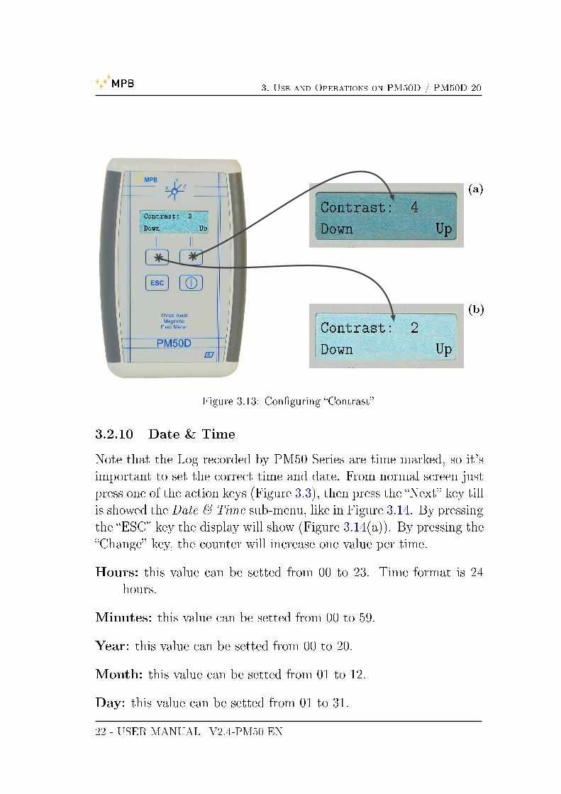
3.2.9 Contrast
Another selectable option is the display contrast. From normal screenjust press one of the action keys (Figure 3.3), then press the �Next� keytill is showed the Logger sub-menu, like in Figure 3.13. By pressingthe �Change� key, the action keys behavior became �Up� and �Down�,so: Contrast goes from level 1 to level 7, as showed in Figure 3.13.
USER MANUAL_V2.4-PM50 EN - 21
3. Use and Operations on PM50D / PM50D-20
Contrast: 3
Down Up
Contrast: 4
Down Up
(a)
Contrast: 2
Down Up
(b)
Figure 3.13: Con�guring �Contrast�
3.2.10 Date & Time
Note that the Log recorded by PM50 Series are time marked, so it'simportant to set the correct time and date. From normal screen justpress one of the action keys (Figure 3.3), then press the �Next� key tillis showed theDate & Time sub-menu, like in Figure 3.14. By pressingthe �ESC� key the display will show (Figure 3.14(a)). By pressing the�Change� key, the counter will increase one value per time.
Hours: this value can be setted from 00 to 23. Time format is 24hours.
Minutes: this value can be setted from 00 to 59.
Year: this value can be setted from 00 to 20.
Month: this value can be setted from 01 to 12.
Day: this value can be setted from 01 to 31.
22 - USER MANUAL_V2.4-PM50 EN

3. Use and Operations on PM50D / PM50D-20
Date & Time
Press ESC to set
Time(HH)00
Next Change
(a)
Figure 3.14: Sub-Menu �Date & Time�
All the possible combinations are showed in Figure 3.15.
• Every time the user press the action keys the menu will beshowed, if no other actions were done the device will automati-cally put back the measuring screen.
• If some setting were changed, it can be saved through the �ESC�key or waiting without pushing any key for the screen to go backin the measuring screen.
• If settings were saved by pressing �ESC� the device menu willstart from the beginning (as in Figure 3.3). Otherwise, if userdoesn't press �ESC� (or any other key) the device seve the valuesanyway, and later, action keys will get back the last Sub-Menuselected.
USER MANUAL_V2.4-PM50 EN - 23

3. Use and Operations on PM50D / PM50D-20
Date & Time
press ESC to setpress ESC
Time(HH)00
Next Changepress Change
Time(HH)01
Next Change
press NextTime(mm)30
Next Changepress Change
Time(mm)31
Next Change
press NextTime(YY)14
Next Changepress Change
Time(YY)15
Next Change
press NextTime(MM)05
Next Changepress Change
Time(MM)06
Next Change
press NextTime(dd)10
Next Changepress Change
Time(dd)11
Next Change
Figure 3.15: �Date & Time� schema
3.3 DATA LOGGER modality
As described in 3.4 the device is able to measure magnetic �eld inreal-time, or used for recording magnetic �eld values for a long periodof time, at some �xed interval selected by users as described in 3.2.7and in 3.2.8. User can start Logging by pressing the �ESC� key fromthe Logger sub-menu(3.11) or the LogTime sub-menu(3.12).
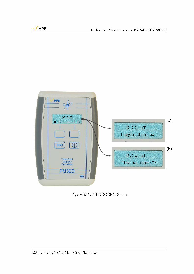
Once the Logger and LogTime parameters are setted just press�ESC� key. The screen will look like Figure 3.16, then press �Start�key for begin to Log. The device will display on the second line amessage to con�rm that the Logger has started. After that no otheraction, beside turn o� the device, will be possible. The state Led will�ash three times per measure every user �xed interval of time(5, 10or 30 seconds). During the data acquisition the second line will showthe words �Logger Running� (Figure 3.17(a)) for the 5 seconds loginterval, or �Time to Next XX � (Figure 3.17(b)) for 10 or 30 seconds
24 - USER MANUAL_V2.4-PM50 EN

3. Use and Operations on PM50D / PM50D-20
***LOGGER***
Next START0.00 uT
Logger Started
(a)
Figure 3.16: �*LOGGER*� Screen
interval.To stop the data acquisition it's necessary turn o� the device. To
visualize acquired data it's necessary the PC software PM50 Managerdescribed in Chapter 5 and Chapter 5.7.
3.4 REAL TIME modality
As the device is turned on, the display shows the real time measuredmagnetic �eld value. The �rst row shows the isotropic value of the�eld in µT or A
m for the PM50D and in mT or kAm for the PM50D-20
(it's possible to choose witch mode users wants as described in 3.2.4).Meanwhile the second line will show what option user has selectedin the �Line2� sub menu (Chapter 3.2.3). In Live acquisition the led�ashes every second.
USER MANUAL_V2.4-PM50 EN - 25
3. Use and Operations on PM50D / PM50D-20
00.0uT
0.00 0.00 0.00
0.00 uT
Logger Started
(a)
0.00 uT
Time to next:25
(b)
Figure 3.17: �*LOGGER*� Screen
26 - USER MANUAL_V2.4-PM50 EN

Chapter 4
Use and Operations on PM50
Like all the series, PM50 doesn't need of an external source of power.PM50 has a rechargeable lithium battery who can be plugged evento a PC for recharges. An entire charge cycle has a duration of 6hours. This model of personal protection equipment doesn't have adisplay, so it can't shows measures in real-time mode, but it can onlyacquire data as a DATA LOGGER setted up from the PC softwarePM50 Manager (see Chapter 5 for reference).
• Before start a Logger acquisition we suggest to complete a rechargecycle of at least 6 hours.
27

4. Use and Operations on PM50
28 - USER MANUAL_V2.4-PM50 EN

Chapter 5
PC Software PM50 Manager
All the PM50 Series can be managed by thePM50 Manager. Throughthis software user can:
• Set up all the Logger customization.
• Download and store acquisitions �le recorded in Data Loggermode.
5.1 Installation
If users don't own the MPB USB mass storage provided with everymodel of PM50 Series, the executable of PM50 Manager can be foundon our website http://www.gruppompb.com/, in the download sec-tion. Search for PM50 Series in the MPB products list and selectthe item in the software column. This will open a dialog window forcredential info. Once all �elds are complete the software downloadwill start.
To install the PC software choose the appropriate executable be-tween PM50Manager_ setup_ 32bit.exe or PM50Manager_ setup_64bit.exe, depending on user's OS architecture, and launch it. The�rst displayed screen will look like Figure 5.1. By click on �Next� thesoftware will ask user's credential (Figure 5.3(a)).
Follow the installer instruction and go ahead to the path selection(Figure 5.3(b)). In the next page user can choose a custom link pathfrom desktop and/or from the Windows �Start� menu, as showed in
29

5. PC Software PM50 Manager
Figure 5.1: Installer PM50 Manager
Figure 5.3(c). Now the software has enough infos, and the installationwill begin (Figure 5.3(d) & Figure 5.3(e)). When all data are correctlyinstalled the last screen (Figure 5.3(f)) will show a report and thePM50 Manager will be ready to go.
• The software doesn't need custom con�guration.
30 - USER MANUAL_V2.4-PM50 EN

5. PC Software PM50 Manager
Figure 5.2: PM50 Manager installer
(a) credential (b) path
(c) link (d) report
(e) installation (f) conclusion
USER MANUAL_V2.4-PM50 EN - 31

5. PC Software PM50 Manager
5.2 Working with PM50, PM50D e PM50D-20
Through the PM50 Manager users can store all generated data andcon�gure the PM50 series for new Logger runs. There is a di�erencedepending on the owned model:
PM50: No operation is needed, just plug the device to the PC.
PM50D / PM50D-20: Device has to be turned on before connect-ing it with the USB cable.
This software is able to recognize witch model is connected to the PC,so there is no need to specify the model code.
Figure 5.3: �Welcome� PM50 Man-ager
If drivers are correctly installed,the PC will recognize the de-vice immediately, otherwise followthe driver installation instruction(see Appendix A). Once the deviceis connected the software can belaunched. On the �rst run you willsee the window as in Figure 5.3.Con�rmed the welcome page, thePM50 Manager will appear (Fig-ure 5.4).
On the left part of main screenare displayed:
• the used COM Port (if con�gured).
• USB connection state.
• the Firmware version of the plugged device.
• the PM50xx internal clock.
• the PM50xx internal date.
• the batteries voltage level.
• the �Archive� button, witch point to the PM50 Manager archivefolder.
32 - USER MANUAL_V2.4-PM50 EN

5. PC Software PM50 Manager
Figure
5.4:
PM50
Manager:MainScreen
USER MANUAL_V2.4-PM50 EN - 33

5. PC Software PM50 Manager
5.3 First Connection
Figure 5.5: �Com Port� Button
Until the connection is not established, the device settings anddownload will be disabled. To connect the device for the �rst time,please select the correct port from the list called �Com Port� (Fig-ure 5.5).
Now the PM50 Manager is ready for connection. Press the �Con-nect� button (Figure 5.6).
Figure 5.6: �Connect� button
All the labels on the left will be updated with the PM50xx deviceinfo. The system is now able to set up all the device con�gurationsand to download acquired data.
34 - USER MANUAL_V2.4-PM50 EN

5. PC Software PM50 Manager
Figure
5.7:
PM50
Manager:PM50xxconnected
USER MANUAL_V2.4-PM50 EN - 35

5. PC Software PM50 Manager
When the PM50xx is connected the screen will look like Figure 5.7.The upper part involves: �Reload con�guration� for a refresh of all thedevice con�guration, �Clock Sync� for set the device clock, �LoggerSetup� and �Alarm Setup�, with every relative value that is updatedduring the connection phase, according the device. If user change oneof these value, he has to con�rm by pressing the relative �Set� button.
5.4 Clock Sync
It's important to relate the measure of the magnetic �eld with thetime of that measure. To make sure that the device clock is updated,just re-sync it with the PC clock by pressing the �Clock Sync� buttonin Figure 5.8.
Figure 5.8: �Clock Sync� button
5.5 Logger Setup
Every model of the PM50 Series has di�erent logging modality (al-ready described in chapters 3.2.6,3.2.7 e 3.2.8). The PM50 Managershows the last con�guration in use on device. For apply a new kindof con�guration press the �Set Logger� button (Figure 5.9), that willbe enabled after any change done. More precisely this part refers tothe Time, Mode or Rate �elds.
36 - USER MANUAL_V2.4-PM50 EN

5. PC Software PM50 Manager
Figure 5.9: �Logger Setup� section
• With the Time �eld setted to 7 days it's only possible a Rate of30 seconds (the Software will block this combination automati-cally).
Once the �Store this Con�guration� button is pressed, check the popupmessage to be sure that the con�gurations are set. In case of errorplease try again.
5.6 Alarm Setup
Even in this section, values are loaded right after the connection. Thealarm boundary depends on the device model:
PM50: from 1 µT to 500 µT.
PM50D: from 1 µT to 500 µT.
PM50D-20: from 0.1 mT to 20.0 mT.
As in the Logger Setup panel, it will be su�cient to edit the valuesand press the �Set Alarm� button to commit the changes. Check thepopup message to be sure that the con�gurations are set.
• The alarm value in this panel will be used for the data plot(Chapter 5.7).
USER MANUAL_V2.4-PM50 EN - 37

5. PC Software PM50 Manager
Figure 5.10: �Alarm Setup� section
5.7 Data Download
Figure 5.11: �Download Last Log� button
By pressing the �Download� button, showed in Figure 5.11, thedata acquired on the device will be plotted in the bottom of thePM50 Manager screen.
In the white part labeled �Last Log Information� will be plottedgeneral info about that log, like date of start, log mode, rate mode, etc.On the right of this label there is the grid view, where data is plottedordered by time. The softwere will mark with asterisks the rows wherethe measured value exceeds the threshold. In addition the measuredvalue is plotted in Tesla and Ampere
metri units. Every download operation
38 - USER MANUAL_V2.4-PM50 EN

5. PC Software PM50 Manager
Figure
5.12:PM50
Manager:DataDow
nload
USER MANUAL_V2.4-PM50 EN - 39

5. PC Software PM50 Manager
will create a .txt �le, that will be stored in the PM50 Manager archive.
40 - USER MANUAL_V2.4-PM50 EN

5. PC Software PM50 Manager
5.8 Data Folder
For user comfort, the management of di�erent Log �les is based onchronological history. PM50 Manager creates folder named by year,then month, while the .txt is named with the date and time so theyremain ordered.
Figure 5.13: �Open Data Folder� button
By pressing the �Archive� button (Figure 5.13), the software willopen a new explorer window on the PM50 Manager AppData folder.
Every .txt �le contains the �last log information� as header, andthen the grid contents, tab separated, so that's easy to import Logdata in a MS Excel sheet.
USER MANUAL_V2.4-PM50 EN - 41

5. PC Software PM50 Manager
Figu
re5.14:
PM50
Manager:
Arch
ive
42 - USER MANUAL_V2.4-PM50 EN

5. PC Software PM50 Manager
5.9 Start new Log
The �Start New Log� button, showed in Figure 5.15, is used to starta new acquisition right away. If on PM50D and PM50D-20 this oper-ation can be done directly from devices, on the PM50 this is the onlyway to launch a new magnetic �eld Log acquisition.
Figure 5.15: �Start New Log� button
The software will ask the user to con�rm this command, becauseonce the Logger is started the serial communication will be inter-rupted. For a new session with the PM50 Manager the Logger has tobe stopped and reconnected as described in Chapter 5.3.
USER MANUAL_V2.4-PM50 EN - 43

5. PC Software PM50 Manager
44 - USER MANUAL_V2.4-PM50 EN

Chapter 6
Firmware PM50D / PM50D-20
The most updated version of PM50xx Firmware can be found on ourwebsite (www.gruppompb.com/download.asp). We advise to alwaysuse the higher version for a better experience.
6.1 Download and install the Updater
In the page cited above, search for MPB product, PM50 series atthe Firmware column to download the updated Firmware compressedpackage. UseWinrar to extract all the �les contained in the PM50D_106 folder as showed in Figure 6.1.
Figure 6.1: �rmware package
Launch one of the executables, depending on your OS architecture,to install the device Updater (Figure 6.2).
45

6. Firmware PM50D / PM50D-20
Figure 6.2: install USB Updater
Follow the instruction and insert your credential like in Figure 6.3(a).Then select a path if you don't want to use the standard one (Fig-ure 6.3(b)). Select the link option (or leave as is for standard) like inFigure 6.3(c). Go ahead to the report page (Figure 6.3(d)) until youreach the �installation complete� message. Now you have the USBUpdater installed.
After the installation you will �nd in the software path a folderthat contains 5 �les as showed in Figure 6.4.
6.2 Firmware Update
To commit the �rmware update launch the USB_UPDATER (Fig-ure 6.4) and wait for the screen showing the window as in Figure 6.5.
Press �Next� and you will see a form like in Figure 6.6 where youneed to select the path of the Firmware �le to install on the device.
Carefully follow this instruction below:
1. Plug the USB cable only on PC side.
46 - USER MANUAL_V2.4-PM50 EN

6. Firmware PM50D / PM50D-20
(a) user credential (b) path
(c) link (d) report
Figure 6.3: PM50 Series FW updater
2. With the device turned o�, plug the cable and immediatly pressand hold the Power key for all the update operation.
3. Now the �Upgrade Firmware� button became enabled, press itand wait a few seconds for the �nish message as in Figure 6.7(b).
Press �OK� and close the program, unplug the PM50xx from thePC.
USER MANUAL_V2.4-PM50 EN - 47

6. Firmware PM50D / PM50D-20
Figure 6.4: USB Updater folder
Figure 6.5: USB Updater for PM50D_106
48 - USER MANUAL_V2.4-PM50 EN

6. Firmware PM50D / PM50D-20
Figure 6.6: Firmware choice for PM50xx
(a) user credential (b) path
Figure 6.7: PM50 Series FW updater
USER MANUAL_V2.4-PM50 EN - 49

6. Firmware PM50D / PM50D-20
50 - USER MANUAL_V2.4-PM50 EN

Appendix A
Technical Notes
The USB device may not be recognized properly if the driver instal-lation procedure isn't followed in detail.
A.1 Troubleshooting in Driver installation
If the PC doesn't recognize the PM50xx it's necessary to follow thisinstructions:
1. Open the control panel of your PC
2. Select the System icon (if you don't �nd it inWindows Vista orWindows 7 choose a di�erent visualization of icons)
3. Click on Device Manager as in Figure A.1
Figure A.1: System
4. In the devices list of your PC will be marked with a warning, asin Figure A.2, because the PM50xx weren't recognized.
51

A. Technical Notes
Figure A.2: Device Manager
5. Perform a right click on that device and select �Update driver�.
6. Click on �Find driver manually�.
7. Now browse for the folder C:/Windows/inf as showed in Fig-ure A.3.
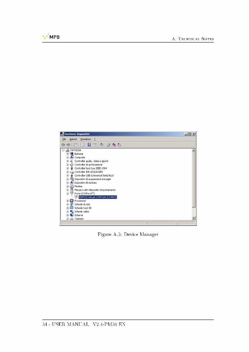
8. Press �Ok� and wait for the system �nd the correct one (namedMSP430_CDC) as in Figure A.4.
9. At the end of this procedure you will notice that the device hasbeen installed properly (Figure A.5) and has the correct drivername.
10. The device is now ready for a normal use. Refer to Chapter 5.
• Figures could be di�erent. It depends on your installed OS.
52 - USER MANUAL_V2.4-PM50 EN

A. Technical Notes
Figure A.3: Find Driver
(a) installing (b) installed
Figure A.4: Driver setup
USER MANUAL_V2.4-PM50 EN - 53
A. Technical Notes
Figure A.5: Device Manager
54 - USER MANUAL_V2.4-PM50 EN

List of Figures
1.1 PM50 Series . . . . . . . . . . . . . . . . . . . . . . . 1
1.2 PM50 front . . . . . . . . . . . . . . . . . . . . . . . 2
1.3 PM50D / PM50D-20 front . . . . . . . . . . . . . . . 3
2.1 block diagram PM50 . . . . . . . . . . . . . . . . . . 7
2.2 block diagram PM50-D e PM50-D-20 . . . . . . . . . 8
3.1 turned on PM50D / PM50D-20 . . . . . . . . . . . . . 9
3.2 measuring display . . . . . . . . . . . . . . . . . . . . 10
3.3 �alarm� menu . . . . . . . . . . . . . . . . . . . . . . 11
3.4 �alarm� selection . . . . . . . . . . . . . . . . . . . . . 12
3.5 Menu �Threshold� . . . . . . . . . . . . . . . . . . . . 13
3.6 Con�guring �Threshold� . . . . . . . . . . . . . . . . . 14
3.7 Con�guring �Line 2� . . . . . . . . . . . . . . . . . . . 15
3.8 Sub-Menu �Unit� . . . . . . . . . . . . . . . . . . . . 16
3.9 Sub-Menu �AutoO�� . . . . . . . . . . . . . . . . . . 17
3.10 Sub-Menu �Mode� . . . . . . . . . . . . . . . . . . . . 18
3.11 Sub-Menu �Logger� . . . . . . . . . . . . . . . . . . . 20
3.12 Sub-Menu �Log Time� . . . . . . . . . . . . . . . . . . 21
3.13 Con�guring �Contrast� . . . . . . . . . . . . . . . . . 22
3.14 Sub-Menu �Date & Time� . . . . . . . . . . . . . . . . 23
3.15 �Date & Time� schema . . . . . . . . . . . . . . . . . 24
3.16 �*LOGGER*� Screen . . . . . . . . . . . . . . . . . . 25
3.17 �*LOGGER*� Screen . . . . . . . . . . . . . . . . . . 26
5.1 Installer PM50 Manager . . . . . . . . . . . . . . . . 30
5.2 PM50 Manager installer . . . . . . . . . . . . . . . . . 31
55

LIST OF FIGURES
5.3 �Welcome� PM50 Manager . . . . . . . . . . . . . . . 325.4 PM50 Manager: Main Screen . . . . . . . . . . . . . . 335.5 �Com Port� Button . . . . . . . . . . . . . . . . . . . 345.6 �Connect� button . . . . . . . . . . . . . . . . . . . . 345.7 PM50 Manager: PM50xx connected . . . . . . . . . . 355.8 �Clock Sync� button . . . . . . . . . . . . . . . . . . . 365.9 �Logger Setup� section . . . . . . . . . . . . . . . . . 375.10 �Alarm Setup� section . . . . . . . . . . . . . . . . . . 385.11 �Download Last Log� button . . . . . . . . . . . . . . 385.12 PM50 Manager: Data Download . . . . . . . . . . . . 395.13 �Open Data Folder� button . . . . . . . . . . . . . . . 415.14 PM50 Manager: Archive . . . . . . . . . . . . . . . . 425.15 �Start New Log� button . . . . . . . . . . . . . . . . . 43
6.1 �rmware package . . . . . . . . . . . . . . . . . . . . 456.2 install USB Updater . . . . . . . . . . . . . . . . . . . 466.3 PM50 Series FW updater . . . . . . . . . . . . . . . . 476.4 USB Updater folder . . . . . . . . . . . . . . . . . . . 486.5 USB Updater for PM50D_106 . . . . . . . . . . . . . 486.6 Firmware choice for PM50xx . . . . . . . . . . . . . . 496.7 PM50 Series FW updater . . . . . . . . . . . . . . . . 49
A.1 System . . . . . . . . . . . . . . . . . . . . . . . . . . 51A.2 Device Manager . . . . . . . . . . . . . . . . . . . . . 52A.3 Find Driver . . . . . . . . . . . . . . . . . . . . . . . 53A.4 Driver setup . . . . . . . . . . . . . . . . . . . . . . . 53A.5 Device Manager . . . . . . . . . . . . . . . . . . . . . 54
56 - USER MANUAL_V2.4-PM50 EN

List of Tables
1.1 Technical speci�cations PM50-Series . . . . . . . . . . 51.2 PM50 Series Accessories . . . . . . . . . . . . . . . . . 6
57