user manual - panasonic · in periods of network congestion, automatic packet transmission rate...
TRANSCRIPT

User Manual
Thank you for purchasing this Panasonic product.
Please read this manual carefully before using this product and save this manual for future use.
Document Version: 2020-03
In this manual, HD Visual Communication is abbreviated as "HDVC".
In this manual, the suffix of each model number (e.g., KX-VCA001XX) is omitted unless necessary.
KX-VC1000, KX-VC1300, KX-VC1600, KX-VC2000: Software File Version 6.00 or later
HD Visual Communication Unit
Model No. KX-VC1000, KX-VC1300, KX-VC1600, KX-VC2000,
KX-VC1000SX, KX-VC1300SX, KX-VC1600SX,
KX-VC2000SX, KX-VC1300A, KX-VC1600A

Introduction
Feature HighlightsDisplay
Video
camera
Display
Intranet
Microphone
Microphone
Video
camera
Display Display
Microphone
Video
camera
Computer
Internet
Router
NAT Traversal
Service
Router
Computer
Lifelike Video Conference CallYou can experience lifelike video conference calls with smooth, high-quality video and clear stereo*1 sound.*1 If using 2 or more Digital Boundary Microphones, stereo output can be enabled through system settings (Page 131). When using
Digital Boundary Microphones and an Analogue Boundary Microphone together, stereo output may be unavailable depending on theconnection configuration (Page 31, Page 33).
Home Electronics-style Remote Control Operation and Simple, Easy toUnderstand Graphical User Interface
You can make settings and perform operations using familiar remote control operations and a simple, easy tounderstand interface.
Stabilised Communication QualityIn periods of network congestion, automatic packet transmission rate quality control prevents packet loss tomaintain a video conference call’s image and sound quality. This allows video conference calls with stabilisedcommunication quality even over an Internet connection or mobile communication.
2 User Manual Document Version 2020-03
Introduction

Dual stream (2 screens) compatibleYou can send the image of your video camera and the image of your computer’s screen or a sub video cameraat the same time to the other party.You can view the other party and check shared data at the same time to hold more realistic and interactivemeetings.
Dual network compatibility (KX-VC1600, KX-VC2000)You can connect to different networks at the same time, such as your company’s internal network and theInternet. This allows seamless connectivity with units both inside and outside of your company.
Multi-party connectionsThe KX-VC1000 can establish connections with 2 parties standard, and is expandable to establish multipleconnections with a maximum of 4 parties. The KX-VC1300 can establish multiple connections with a maximumof 4 parties. The KX-VC1600 can establish multiple connections with a maximum of 6 parties standard, and isexpandable to a maximum of 10 parties. The KX-VC2000 can establish multiple connections with a maximumof 16 parties standard, and is expandable to a maximum of 20 or 24 parties. All devices have MCU functionsbuilt-in, allowing for flexible connectivity.
Note• In this manual, 1 unit with a built-in MCU which connects to multiple sites simultaneously is referred
as to the "Main Site", and the sites connecting to the Main Site are referred to as "Sub Sites". A sitethat establishes connections to multiple sites using a Profile Call (Page 54), or a site that adds a siteto the call during a 2-party video conference call with another site (Page 67) becomes the "MainSite".
Selectable Video SourceBy connecting your computer or video camera to the unit, you can show your computer’s screen or videocamera image to video conference call participants (Page 90).
Encrypted CommunicationPackets sent for video conference calls can be encrypted to prevent packet leaks, tampering, oreavesdropping.
KX-VC Series NAT Traversal Service"KX-VC Series NAT Traversal Service" is a service that allows you to easily and affordably set up and operatea communication environment for the HD Visual Communication Unit.*1*2*3 Also, complicated routerconfiguration is unnecessary, which allows even people who are not network administrators set up acommunication environment. Furthermore, you can assign the unit a unique number (Terminal ID), whichallows the unit to be called not by IP address, but with the unique 7-digit number. This means communicationcan be initiated as if calling a telephone. Communication can also be encrypted, so that you can communicateover the Internet safely and securely.
For details about KX-VC Series NAT Traversal Service, refer to the following web site:
Document Version 2020-03 User Manual 3
Introduction

https://panasonic.net/cns/psn/products/hdvc/nat/nat_traversal/index.html*1 This service may be unavailable depending on the country/area of use. For details, contact your dealer.*2 This service may be unavailable depending on your router’s type or your Internet connection environment. For details, contact your
dealer.*3 IPv6 addresses cannot be used.
Making Video Conference Calls via SIP ServerBy using a SIP server, you can establish video conference calls not just by IP address, but also by specifyinga SIP URI (SIP user name@SIP domain name) instead. If the other party uses the same SIP domain nameas you, you can make a video conference call by specifying only the SIP user name. For information aboutsupported SIP servers, contact your dealer.
Calling via an H.323 GatekeeperGoing through an H.323 Gatekeeper allows communication of not just the IP address, by the H.323 extensionand the H.323 name as well. Contact your dealer regarding the gatekeepers that can be used.
Enhanced Features through the Use of Activation KeysBy using an activation key (sold separately), you can upgrade the features of the unit (Page 20). This allowsenrolment in the KX-VC Series NAT Traversal Service, and enables enhanced features (Mobile Connection,Multicast, USB Device Mode, and Web Hybrid Mode).If using the KX-VC2000, multiple connections can be made with up to 20 or 24 parties simultaneously. If usingthe KX-VC1600, multiple connections can be made with up to 10 parties simultaneously. The KX-VC1000 canestablish connections with a maximum of 4 parties and also supports dual monitors.
Remote Video Camera Operation via Remote ControlYou can move your own video camera up, down, left, and right as well as zoom in and out (Page 93). Youcan also register up to 12 preset patterns of video camera direction and zoom level which allows you to easilychange the video camera’s direction and zoom level by selecting a preset (Page 96, Page 99). Additionally,you can also use your remote control to control the other party’s video camera.*1
*1 To be able to control another party’s video camera, settings must be configured on the other party’s unit (Page 133).
IPv6 AddressCommunication can be made using IPv6 addresses. IPv6 addresses can also be used for SIP Servers and H.323 Gatekeepers.
USB RecordingYou can record video and audio of conferences and save them on a USB memory device that is connected tothe USB jack on the back of the unit (Page 83, Page 134, Page 187).
4 User Manual Document Version 2020-03
Introduction

Trademarks• The terms HDMI, HDMI High-Definition Multimedia Interface, and the HDMI Logo are trademarks or
registered trademarks of HDMI Licensing Administrator, Inc.• Polycom® is a trademark owned by Polycom, Inc. in the US and other countries.• Microsoft, Internet Explorer, Windows, and Windows Media are either registered trademarks or trademarks
of Microsoft Corporation in the United States and/or other countries.• Mozilla and Firefox are trademarks of the Mozilla Foundation in the US and other countries.• QuickTime is a trademark of Apple Inc., registered in the U.S. and other countries.• All other trademarks identified herein are the property of their respective owners.
Licences• THIS PRODUCT IS LICENSED UNDER THE AVC PATENT PORTFOLIO LICENSE FOR THE
PERSONAL USE OF A CONSUMER OR OTHER USES IN WHICH IT DOES NOT RECEIVEREMUNERATION TO (i) ENCODE VIDEO IN COMPLIANCE WITH THE AVC STANDARD (“AVCVIDEO”) AND/OR (ii) DECODE AVC VIDEO THAT WAS ENCODED BY A CONSUMER ENGAGED IN APERSONAL ACTIVITY AND/OR WAS OBTAINED FROM A VIDEO PROVIDER LICENSED TO PROVIDEAVC VIDEO. NO LICENSE IS GRANTED OR SHALL BE IMPLIED FOR ANY OTHER USE. ADDITIONALINFORMATION MAY BE OBTAINED FROM MPEG LA, L.L.C. SEE HTTP://WWW.MPEGLA.COM
• This product incorporates G.722.1 and G.722.1 Annex C licensed by Polycom®.• This product incorporates Qt library licenced by Digia Plc. Please read "EULA" of system settings of this
product.
Open Source SoftwareParts of this product use Open Source Software supplied based on the conditions of the Free SoftwareFoundation’s GPLs and/or LGPLs, and the conditions of the ITU-T and other conditions. Relevant conditionsapply to this software. Therefore, please read license information about GPLs, LGPLs, and ITU-T, and"License Info." of system settings of this product before using this product. Also, some software parts of thisproduct are licensed under the MOZILLA PUBLIC LICENSE (MPL). At least three (3) years from delivery ofproducts, Panasonic will give to any third party who contacts us at the contact information provided below, fora charge of no more than the cost of physically distributing source code, a complete machine-readable copyof the corresponding source code and the copyright notices covered under GPL, LGPL, MPL, and ITU-T.Please note that software licensed under GPL, LGPL, MPL, and ITU-T is not under warranty.
Contact Informationhttp://www.panasonic.net/corporate/global_network/
MiscellaneousAbout the Screen Shots and Illustrations in this Manual
The screen shots and descriptions in this manual are based on using the KX-VC2000 (when used withenhanced features). However, some of the screens shots are based on using the KX-VC1600. If you are usingthe KX-VC1000, KX-VC1300, KX-VC1600, or KX-VC2000 (without using the enhanced features), please notethat some displayed features will not be available for your model. Also please note that the illustrations in thismanual are based on using the KX-VC1600.
Document Version 2020-03 User Manual 5
Introduction

Copyright• The software used in this product uses source code from Radvision Ltd.
Portions of this software are © 1996-2012 RADVISION Ltd. All intellectual property rights in such portionsof the Software and documentation are owned by RADVISION and are protected by United States copyrightlaws, other applicable copyright laws and international treaty provisions. RADVISION and its suppliersretain all rights not expressly granted.
• Except for open source software licensed under GPL/LGPL and so on, distributing, copying, disassembling,reverse compiling and reverse engineering of the software provided with this product are all expresslyprohibited. In addition, exporting any software provided with this product violating export laws is prohibited.
6 User Manual Document Version 2020-03
Introduction

Table of ContentsFor Your Safety ......................................................................................11
For Your Safety ...............................................................................................................11
Before Operation ....................................................................................13Notes about Operation ...................................................................................................13Data Security ...................................................................................................................14Privacy and Right of Publicity .......................................................................................14
Precaution ...............................................................................................15Precaution ........................................................................................................................15
Preparation .............................................................................................17Accessory/Optional Accessory Information ................................................................17Optional Accessory ........................................................................................................18Part Names and Usage ...................................................................................................22
Main Unit (Front) ............................................................................................................22Main Unit (Back) .............................................................................................................23Remote Control ..............................................................................................................25LED Indication ................................................................................................................27Screen Standby ..............................................................................................................27
Connection and Preparation ..........................................................................................29Device and Network Connection ....................................................................................29Connecting the Unit ........................................................................................................30Network Configuration Example .....................................................................................37Preparing the Remote Control ........................................................................................39
Turning the Power On/Off ..............................................................................................40Screen Display ................................................................................................................41
Home Screen (Idle Screen) ............................................................................................41Menu Screen (Idle Screen) ............................................................................................44Video Conference Call Screen .......................................................................................45
Entering characters ........................................................................................................47About IPv6 Addresses ....................................................................................................47Initial Settings ..................................................................................................................48
Starting a Video Conference .................................................................51Making a Video Conference Call ....................................................................................51
Calling Using One-Touch Connection Numbers From the Home Screen ......................51Calling from the Contact List (2-party Conference) ........................................................52Calling Using Profile (Multiple-party Video Conference Calls) .......................................54Calling by Entering an Address Directly .........................................................................56Calling from the Call History ...........................................................................................59
Answering a Video Conference Call ..............................................................................63Connecting to an MCU ....................................................................................................65
During Video Conference Calls ............................................................67Adding Parties to an Existing Video Conference Call (Except Sub Sites) ................67Adding Parties to an Existing Video Conference Call (Except Main Sites) ...............69Disconnecting Parties During Video Conference Call .................................................70Changing the Contents Sharing Method During Communication ..............................71Changing the Screen Layout during a Video Conference Call ...................................72Changing the Other Party’s Screen Display Layout ....................................................73Changing the MCU Mode (Main Site Only) ...................................................................78
Document Version 2020-03 User Manual 7
Table of Contents
Changing the Setting of the Main Display (Main Site only) .........................................79Changing the Site Name Display (Main Site only) .......................................................81Changing the Audio Settings for Other Parties (Main Site only) ................................82Changing the Settings for Audio Mixing Sites (Main Site Only) .................................83Starting and Stopping Recording ..................................................................................83Displaying how the PC is connected ............................................................................84Checking the Call History ...............................................................................................85Adjusting the Volume .....................................................................................................86Muting the Microphone ...................................................................................................87Reducing Microphone Noise ..........................................................................................89Displaying a Computer’s Screen and the Sub Video Camera’s Image ......................90
Controlling a Video Camera ..................................................................93Controlling a Video Camera ...........................................................................................93Registering a Preset .......................................................................................................96Recalling a Registered Preset ........................................................................................99Changing Video Camera Settings ...............................................................................101
Displaying the Connection Status ......................................................105Displaying the Connection Status ...............................................................................105Displaying Unit Information .........................................................................................106
Contacts and Settings .........................................................................107Adding Contacts to the Contact List ...........................................................................107
Registering a New Contact ...........................................................................................107Editing Contact Information ..........................................................................................108Deleting a Contact ........................................................................................................108Registering a Contact from the Call History .................................................................109
Registering a Profile .....................................................................................................110Registering a New Profile .............................................................................................110Editing Profile Information ............................................................................................113Deleting a Profile ..........................................................................................................113Setting the Profile Standby ...........................................................................................114Removing a Profile Standby .........................................................................................114
Making Local Site Settings ...........................................................................................115Registering a Local Site ...............................................................................................115Selecting a Local Site ...................................................................................................115Deleting Local Site Information ....................................................................................116
Changing System Settings/Performing System Maintenance ..................................117Setting the Unit Name ..................................................................................................120Setting the Date and Time ............................................................................................120Making Network Settings ..............................................................................................120Making Connection Settings .........................................................................................123Setting the MCU ...........................................................................................................126Setting One-touch Connection Numbers ......................................................................129Making Screen Standby Settings .................................................................................130Making Sound Settings ................................................................................................130Setting the MIC Position ...............................................................................................131Making Remote Control Settings ..................................................................................132Changing Video Camera Settings ................................................................................133Making Language Settings ...........................................................................................134Making Recording Settings ..........................................................................................134Setting the USB Device Mode ......................................................................................135Setting the Web Hybrid Mode ......................................................................................136Using Multicast .............................................................................................................137
8 User Manual Document Version 2020-03
Table of Contents

Display Unit Information ...............................................................................................137Checking Enhanced Features ......................................................................................137Performing a Network Test ...........................................................................................138Performing Self Diagnosis ............................................................................................138Displaying the Licence Information ..............................................................................138Displaying the End-User Licence Agreement ...............................................................139Performing Remote Maintenance .................................................................................139
Making Administrator Menu Settings ..........................................................................140Administrator Menu List ................................................................................................140Making Administrator Password Settings .....................................................................144Making Encryption Settings ..........................................................................................144Making Software Update Settings ................................................................................145Making Connection Mode Settings ...............................................................................146Making NAT Settings ....................................................................................................146Making Call Type Settings ............................................................................................147Making SIP Settings .....................................................................................................148Making H.323 Settings .................................................................................................149Making Codec Settings ................................................................................................150Making Security Settings ..............................................................................................150Making Video Output Settings ......................................................................................152Making Audio Input/Output Settings .............................................................................154Making GUI Settings ....................................................................................................155Making HDMI Settings ..................................................................................................156Setting Power Management .........................................................................................156Setting Shortcuts ..........................................................................................................157Setting Local Site Selection ..........................................................................................158Setting Multicast Tree ...................................................................................................158Transferring Contact Lists ............................................................................................158Activating Enhanced Features .....................................................................................159Updating Software ........................................................................................................160Initialising a Video Camera ...........................................................................................162Performing System Initialisation ...................................................................................162Setting Remote Access ................................................................................................162Exporting Data ..............................................................................................................163Importing Data ..............................................................................................................164
Using the KX-VC Series NAT Traversal Service ................................166Using the KX-VC Series NAT Traversal Service .........................................................166
Preparations for Connections .......................................................................................166KX-VC Series NAT Traversal Service Setup Procedure ..............................................166Connect to the Internet .................................................................................................168Obtain a Registration Key ............................................................................................168
To check the MPR ID (using the unit) ........................................................................168To obtain a Registration Key (using a computer) ......................................................169To display the Registration Key again (using a computer) ........................................170
Using Mobile Connection Enhanced Features ..................................174Using Mobile Connection Enhanced Features ...........................................................174
Using Multicast .....................................................................................175Using Multicast ..............................................................................................................175
About Multicast .............................................................................................................175Multicast Operation ......................................................................................................176
Starting Multicast .......................................................................................................176Ending the Multicast ..................................................................................................176
Document Version 2020-03 User Manual 9
Table of Contents

Handling of Trouble During a Multicast .....................................................................176The Multicast Tree .........................................................................................................177About the Network ........................................................................................................177Setting the System ........................................................................................................178
Setting Multicast ...........................................................................................................178Making Administrator Menu Settings ..........................................................................178
Registering the Multicast Tree ......................................................................................178Starting a Multicast .......................................................................................................182
Starting a Multicast .......................................................................................................182Starting a Multicast by Selecting the Multicast Target ..................................................183Confirming the Transmission Status During a Multicast (Multicast Terminal) ..............185Confirming the Transmission Status During a Multicast (Relay Terminal/ReceiverTerminal) ......................................................................................................................186Starting and Stopping Recording During a Multicast ....................................................186
Using USB Recording Features ..........................................................187Using USB Recording Features ...................................................................................187
Using USB Device Mode ......................................................................190Using USB Device Mode ...............................................................................................190
Using Web Hybrid Mode ......................................................................192Using Web Hybrid Mode ...............................................................................................192
Miscellaneous .......................................................................................194Changing the Remote Control Batteries .....................................................................194Cleaning the Unit ...........................................................................................................195
Input ......................................................................................................196Inputting Letters and Numbers ....................................................................................196
Port numbers ........................................................................................209Port numbers .................................................................................................................209
Additional Information .........................................................................212Troubleshooting ............................................................................................................212
Basic Operation ............................................................................................................212Audio ............................................................................................................................218System Settings ...........................................................................................................220If These Messages Appear ..........................................................................................220Registration Page of KX-VC Series NAT Traversal Service ........................................228KX-VC Series NAT Traversal Service for this Device ..................................................229If a message from the KX-VC Series NAT Traversal Service is displayed ..................229
Specifications .......................................................................................232System Specifications ..................................................................................................232
Index............................................................................................................235
10 User Manual Document Version 2020-03
Table of Contents

For Your Safety
CAUTION
RISK OF ELECTRIC SHOCK DO NOT OPEN
CAUTION: TO REDUCE THE RISK OF ELECTRIC SHOCK, DO NOT REMOVE COVER (OR BACK).
NO USER-SERVICEABLE PARTS INSIDE.REFER SERVICING TO QUALIFIED SERVICE PERSONNEL.
The lightning flash with arrowheadsymbol, within an equilateral triangle, isintended to alert the user to the presenceof uninsulated "dangerous voltage" withinthe product’s enclosure that may be ofsufficient magnitude to constitute a risk ofelectric shock to persons.
The exclamation point within anequilateral triangle is intended to alert theuser to the presence of importantoperating and maintenance (servicing)instructions in the literatureaccompanying the appliance.
WARNING:• The mains plug or an appliance coupler shall
remain readily operable.• To prevent fire or electric shock hazard, do not
expose this apparatus to rain or moisture.• The apparatus should not be exposed to dripping or
splashing and no objects filled with liquids, such asvases, should be placed on the apparatus.
• All work related to the installation of this productshould be made by qualified service personnel orsystem installers.
• The connections should comply with local electricalcode.
• Batteries (battery pack or batteries installed) shallnot be exposed to excessive heat such as sunshine,fire or the like.
• This is a class A product. In a domestic environmentthis product may cause radio interference in whichcase the user may be required to take adequatemeasures.
• This equipment is compliant with Class A of CISPR32. In a residential environment this equipment maycause radio interference.
• Operation of this equipment in a residentialenvironment could cause radio interference.
• Do not use your headset at a high volume. The useof excessive sound volume through a headset maycause hearing loss.
CAUTION:• Before attempting to connect or operate this
product, please read the label on the bottom.• Be sure to use the specified type of batteries only.• Ensure that batteries are installed with correct
polarity. Incorrectly installed batteries can burst orleak, resulting in spillage or injuries.
• This product contains batteries. Replace only withthe same or equivalent type. Improper use orreplacement may cause overheating, rupture orexplosion resulting in injury or fire. Dispose of usedbatteries according to the instructions of your localsolid waste officials and local regulations.
• When replacing the batteries for the remote control,use R6 (AA) type dry cell.
For use only with power supply Panasonic,PGLV1006. (KX-VC1000SX, KX-VC1300SX,KX-VC1600SX)For use only with power supply Panasonic,PGLV1011. (KX-VC1300A, KX-VC1600A)For use only with power supply Panasonic,PGLV1017. (KX-VC1000, KX-VC1300, KX-VC1600,KX-VC2000, KX-VC2000SX)
For U.S.: KX-VC1300A, KX-VC1600A, KX-VC2000For Canada: KX-VC1000, KX-VC1300, KX-VC1600,KX-VC2000, KX-VC1300A, KX-VC1600AFor Europe and other countries: KX-VC1000,KX-VC1300, KX-VC1600, KX-VC2000,KX-VC1000SX, KX-VC1300SX, KX-VC1600SX,KX-VC2000SX
UL listed model No.:KX-VC1300A, KX-VC1600A, KX-VC1000, KX-VC1300, KX-VC1600, KX-VC2000
Important Safety Instructions:1) Read these instructions.
2) Keep these instructions.
3) Heed all warnings.
4) Follow all instructions.
5) Do not use this apparatus near water.
6) Clean only with dry cloth.
Document Version 2020-03 User Manual 11
For Your Safety
For Your Safety
7) Do not block any ventilation openings. Installin accordance with the manufacturer’sinstructions.
8) Do not install near any heat sources such asradiators, heat registers, stoves, or otherapparatus (including amplifiers) that produceheat.
9) Protect the power cord from being walked onor pinched particularly at plugs, conveniencereceptacles, and the point where they exitfrom the apparatus.
10) Only use attachments/accessories specifiedby the manufacturer.
11) Unplug this apparatus during lightning stormsor when unused for long periods of time.
12) Refer all servicing to qualified servicepersonnel. Servicing is required when theapparatus has been damaged in any way,such as power-supply cord or plug isdamaged, liquid has been spilled or objectshave fallen into the apparatus, the apparatushas been exposed to rain or moisture, doesnot operate normally, or has been dropped.
12 User Manual Document Version 2020-03
For Your Safety

Notes about OperationPlease pay attention to the following points when usingthis device:1. Please contact your dealer for installing,
upgrading, or repairing this device.
2. Do not forcefully hit or shake this device.Dropping or bumping this device can damage orbreak this device.
3. Do not place this device in a freezer or otherlocation where it is exposed to coldtemperatures.Doing so may result in damage or malfunctions.
4. Place this device at least 2 m (6.5 ft) away fromradios, office equipment, microwave ovens, airconditioning units, etc.Noise from electronic devices can cause static andinterference in other devices.
5. Do not place this device in a location where it isexposed to hydrogen sulfide, phosphorous,ammonia, sulfur, carbon, acid, dirt, toxic gas,etc.Doing so may result in damage, and the usablelife-span of the device may decrease.
6. Do not apply insecticides or other volatileliquids to the device, nor leave rubber bands orvinyl objects on the device for extended periodsof time.Doing so may result in alterations to the material orpaint peeling off the device.
7. Do not bring cards with magnetic strips, suchas credit cards and telephone cards, near themicrophone.Cards might become unusable.
8. Do not bring the device near items that emitelectromagnetic waves or that are magnetised(high-frequency sewing machines, electricwelders, magnets, etc.).Doing so may result in static noise or damage.
9. Keep the device at least 10 cm (4 in) away fromall walls.If placed against a wall, the device may not be ableto ventilate properly, which may lead to a systemmalfunction due to overheating.
10. Avoid placing the device in areas with highhumidity, and exposing it to rain.Neither the main unit nor the power plug is waterresistant.
11. The power outlet should be near the productand easily accessible.
About the Operating EnvironmentThis device includes a feature that automatically adjustsvoice transmissions to improve clarity. After beginninga video conference call, adjustments to the callenvironment may not complete immediately, and as aresult voices may cut out or echo. In such cases, at thebeginning of the video conference call, be sure to speakin turn with other parties.
About Moving the DeviceDo not move this device while cords are still connected.Doing so may result in damage to the cords.
Other• The unit may not operate in the event of a power
failure.• After unpacking the product, dispose of the power
plug cap and packing materials appropriately.
Document Version 2020-03 User Manual 13
Before Operation
Before Operation

Data SecurityWe recommend observing the security precautionsdescribed in this section, in order to prevent thedisclosure of sensitive information.Panasonic is not responsible for any damagescaused by improper use of this device.
Preventing Data LossKeep a separate record of the encryption key and allinformation stored in the contact list.
Preventing Data Disclosure• Do not place this device in a location that can be
accessed or removed without authorisation.• If important information is saved on this device,
store it in an appropriate location.• Do not store sensitive personal information in the
unit.• In the following situations, make a record of the
encryption key and the information stored in thecontact list and return the unit to the state it was inwhen purchased.– Before lending or disposing of the unit– Before handing the unit over to a third party– Before having the unit serviced
• Make sure the unit is serviced by only a certifiedtechnician.
This device can register and store personal data (thecontact list, encryption key, connection history, etc.). Inorder to prevent the disclosure of data stored on thisdevice, make sure to delete all data that is registeredand stored on this device prior to disposing of, lending,or returning this device.
Preventing Data Disclosure over theNetwork• To ensure the security of private conversations,
only connect the unit to a secure network.• To prevent unauthorised access, only connect the
unit to a network that is properly managed.• Make sure all computers connected to the unit
employ up-to-date security measures.• To prevent illegal access from the Internet, activate
a Firewall.
Privacy and Right ofPublicityBy installing and using this device, you are responsiblefor maintaining the privacy and usage rights of imagesand other data (including sound picked up by themicrophone). Use this device accordingly.
• Privacy is generally said to be, "A legal guaranteeand right not to have the details of one’s personallife unreasonably publicised, and the right to be ableto control information about oneself. In addition,right of publicity is a right not to have a likeness ofone’s face or figure photographed and publicisedwithout consent".
• When Automatic Answer or Forced Answering isset as an answer method for incoming calls,transmission begins as soon as a video conferencecall is received (Page 123). The receiver of thevideo conference call will begin transmitting as soonas the video conference call is received at any time,from any caller. Please be aware when theAutomatic Answer feature or Forced Answeringfeature is enabled, there is a risk that due to anunexpected, automatically answered videoconference call, privacy rights may be violated orsensitive information may be transmitted tounauthorised parties.
14 User Manual Document Version 2020-03
Before Operation

PrecautionFor users in the United KingdomFOR YOUR SAFETY, PLEASE READ THEFOLLOWING TEXT CAREFULLY.
This appliance is supplied with a moulded three-pinmains plug for your safety and convenience. Should thefuse need to be replaced, please ensure that thereplacement fuse is of the same rating and that it isapproved by ASTA or BSI to BS1362.
Check for the ASTA mark or the BSI mark on
the body of the fuse.
If the plug contains a removable fuse cover, you mustensure that it is refitted when the fuse is replaced. If youlose the fuse cover, the plug must not be used until areplacement cover is obtained. A replacement fusecover can be purchased from your local Panasonicdealer.
IF THE FITTED MOULDED PLUG IS UNSUITABLEFOR THE AC OUTLET IN YOUR PREMISES, THENTHE FUSE SHOULD BE REMOVED AND THE PLUGCUT OFF AND DISPOSED OF SAFELY. THERE IS ADANGER OF SEVERE ELECTRICAL SHOCK IF THECUT-OFF PLUG IS INSERTED INTO ANY 13 AMPSOCKET.
How to replace the fuse: Open the fuse compartmentwith a screwdriver and replace the fuse and fuse cover.
For users in the European Union only
Disposal of Old Equipment and BatteriesOnly for European Union and countries withrecycling systems
These symbols on the products, packaging,and/or accompanying documents mean thatused electrical and electronic products andbatteries must not be mixed with generalhousehold waste.For proper treatment, recovery andrecycling of old products and used batteries,please take them to applicable collectionpoints in accordance with your nationallegislation.End users are legally obliged in Germany toreturn used batteries to a suitable collectionpoint. Batteries can be returned free ofcharge in the trading business.In Spain, users are required to deliver thebatteries at the corresponding collectionpoints. In any case, the delivery by the userswill be free of charge for them. The cost ofenvironmental management of wastebatteries, accumulators and batteries isincluded in the sale price.By disposing of them correctly, you will helpto save valuable resources and prevent anypotential negative effects on human healthand the environment.For more information about collection andrecycling, please contact your localauthority.Penalties may be applicable for incorrectdisposal of this waste, in accordance withnational legislation.
For business users in the EuropeanUnionIf you wish to discard electrical andelectronic equipment, please contact yourdealer or supplier for further information.
Information on disposal in othercountries outside the European UnionThese symbols are only valid in theEuropean Union. If you wish to discard theseitems, please contact your local authoritiesor dealer and ask for the correct method ofdisposal.
Document Version 2020-03 User Manual 15
Precaution
Precaution

Note for the battery symbol(bottom symbol)This symbol might be used in combinationwith a chemical symbol. In this case itcomplies with the requirement set by theDirective for the chemical involved.
For users in Taiwan only
Notice• This product contains a CR coin lithium battery.
When disposing of the product, the battery mustbe removed. Contact your dealer for details.
Direct current symbol
Alternating current symbol
This symbol indicates a warningsymbol could get hot and there isa possible RISK of a burn iftouched.
For Malaysia Battery RegulationPanasonic Malaysia Sdn. Bhd.Lot 10, Jalan 13/2, 46200 Petaling Jaya, SelangorDarul Ehsan, Malaysia
For users in Germany only• Machine Noise Information Ordinance, 3rd
GPSGV: The highest sound pressure level is 70 dB(A) or less according to EN ISO 7779.
• This equipment is not for use at video display workstations according to BildscharbV.
For CanadaCAN ICES-3(A)/NMB-3(A)
For U.S.A.This product contains a CR Coin Cell Lithium Batterywhich contains Perchlorate Material - special handlingmay apply.
See www.dtsc.ca.gov/hazardouswaste/perchlorate/
FCC Note: This equipment has been tested and foundto comply with the limits for a Class A digital device,pursuant to Part 15 of the FCC Rules. These limits aredesigned to provide reasonable protection againstharmful interference when the equipment is operated ina commercial environment. This equipment generates,uses, and can radiate radio frequency energy and, if notinstalled and used in accordance with the instructionmanual, may cause harmful interference to radiocommunications. Operation of this equipment in aresidential area is likely to cause harmful interferencein which case the user will be required to correct theinterference at his own expense.
FCC Caution: To assure continued compliance,(example - use only shielded interface cables whenconnecting to other devices). Changes or modificationsnot expressly approved by the party responsible forcompliance could void the user’s authority to operatethe equipment.
The model number and serial number of this productmay be found on the surface of the unit. You should notethe model number and serial number of this unit in thespace provided and retain this book as a permanentrecord of your purchase to aid identification in the eventof theft.
Model No.
Serial No.
Disposal may be regulated in your community due toenvironmental considerations. For disposal or recyclinginformation, please visit Panasonic website: https://www.panasonic.com/us/corporate/sustainability.html or call 1-888-769-0149.
16 User Manual Document Version 2020-03
Precaution

Accessory/Optional Accessory InformationThe following accessories are included:
Included AccessoriesAccessories Quantity
AC adaptorPart No.:PGLV1006 (KX-VC1000SX, KX-VC1300SX,KX-VC1600SX)Part No.:PGLV1011 (KX-VC1300A, KX-VC1600A)Part No.:PGLV1017 (KX-VC1000, KX-VC1300, KX-VC1600,KX-VC2000, KX-VC2000SX)
1
Power cord Depends on country/area
Remote controlPart No.:N2QAYB001001 (KX-VC1000SX, KX-VC1300SX,KX-VC1600SX, KX-VC2000SX, KX-VC1300A, KX-VC1600A)Part No.:PGVF2294ZAV1 (KX-VC1000, KX-VC1300, KX-VC1600,KX-VC2000)
1
BatteriesR6 [AA] dry cell (KX-VC1000, KX-VC1300, KX-VC1600,KX-VC2000, KX-VC1300A, KX-VC1600A)LR6 [AA] dry cell (KX-VC1000SX, KX-VC1300SX, KX-VC1600SX,KX-VC2000SX)
2
Note• The number and type of power cords may vary depending on the country/area of use. Please use
whichever is appropriate for the country/area.
Document Version 2020-03 User Manual 17
Preparation
Preparation

Optional AccessoryThe following products are available as optional accessories.
Proprietary main video cameraProprietary main video camera
12x optical/10x digital zoomPan/tilt function supported
Proprietary main video camera3x optical/4x digital zoomPan/tilt function supported
Model No.: KX-VD170 Model No.: GP-VD131
18 User Manual Document Version 2020-03
Preparation
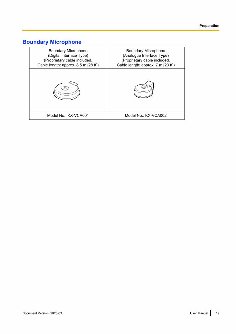
Boundary MicrophoneBoundary Microphone(Digital Interface Type)
(Proprietary cable included.Cable length: approx. 8.5 m [28 ft])
Boundary Microphone(Analogue Interface Type)
(Proprietary cable included.Cable length: approx. 7 m [23 ft])
Model No.: KX-VCA001 Model No.: KX-VCA002
Document Version 2020-03 User Manual 19
Preparation

Activation KeysYou can enhance the following types of features with an activation key. For details about the settings, refer to"Activating Enhanced Features" (Page 159).
Model No. Product Name ActivationKey Type Target Model Description
KX-VCS302 Activation Key (Multicast) Multicast
KX-VC1000KX-VC1300KX-VC1600KX-VC2000
Enables the multicastfeature.
KX-VCS304 Activation Key (4 PointBuilt-in MCU)
4 PointBuilt-in MCU KX-VC1600
Enables the featurefor makingmultiple-party videoconference calls with10 parties, ratherthan the defaultmaximum of 6parties.
KX-VCS305Activation Key (4 Point
Built-in MCU for KX-VC2000)
4 PointBuilt-in MCU KX-VC2000
Enables the featurefor makingmultiple-party videoconference calls with20 or 24 parties,rather than thedefault maximum of16 parties.
KX-VCS314Activation Key (4 Point
Built-in MCU forKX-VC1000)
4 PointBuilt-in MCU KX-VC1000
Can establishconnections with amaximum of 4parties.
KX-VCS351 Activation Key (MobileConnection)
MobileConnection
KX-VC1000KX-VC1300KX-VC1600
Connects to a mobiledevice in IP Mode.
KX-VCS352Activation Key (Mobile
Connection for KX-VC2000)
MobileConnection KX-VC2000
Connects to a mobiledevice in IP Mode.
KX-VCS402Activation Key (HDMI for
KX-VC1000 Dual Monitor)
HDMI DualMonitor KX-VC1000
Enables HDMI2output.
KX-VCS701 Activation Key (NATTraversal 1 Year)
NATTraversal 1
Year
KX-VC1000KX-VC1300KX-VC1600KX-VC2000
Extends the serviceperiod of KX-VCSeries NAT TraversalService.
KX-VCS703 Activation Key (NATTraversal 3 Years)
NATTraversal 3
Years
KX-VC1000KX-VC1300KX-VC1600KX-VC2000
Extends the serviceperiod of KX-VCSeries NAT TraversalService.
20 User Manual Document Version 2020-03
Preparation

Model No. Product Name ActivationKey Type Target Model Description
KX-VCZ501 PC Peripheral kit*1 PCPeripheral
KX-VC1000KX-VC1300KX-VC1600KX-VC2000
Enables the USBDevice Mode feature.
KX-VCZ502 Web hybrid modeexpansion kit*1
Web hybridmode
expansion
KX-VC1000KX-VC1300KX-VC1600KX-VC2000
Enables the WebHybrid Mode feature.
*1 The activation key and proprietary USB conversion cable are included.
Document Version 2020-03 User Manual 21
Preparation

Part Names and Usage
Main Unit (Front)
A B
D E
C
Power LEDShows the power status. The LED is green or red when power is being supplied from the AC adaptor, andoff when power is not being supplied.Remote Control Signal ReceiverReceives Remote Control signals. The maximum range of reception is approximately 8 m (26.2 ft) fromfront of the unit, and approximately 3 m (9.8 ft) from 20° on each side, total 40°.Headset Input-Output TerminalUsed to connect a headset to the unit (Page 34).
Note• If a headset is connected, audio from the other party can be heard through the headset. Audio is
not played through the display or speakers. However, if "Output local site sound" is set to"HDMI", audio is output via HDMI, not the headset (Page 154).
• If a headset is connected, how audio is sent to the other party differs depending on the type ofdevices connected as follows:
Connected Device Audio Sent to Other Party
Boundary Microphone Audio is picked up only by the headset microphone. Audiois not picked up by the Boundary Microphones.
General-purpose microphone Both the general-purpose microphones and the headsetmicrophone pick up audio.
Boundary Microphone andgeneral-purpose microphone
Both the general-purpose microphones and the headsetmicrophone pick up audio. The Boundary Microphones donot pick up audio.
Power buttonTurns the power on and off (Page 40).Status LEDShows the operational status of the unit (Page 27).
22 User Manual Document Version 2020-03
Preparation

Main Unit (Back)KX-VC1600*, KX-VC2000*
A B C D F
K M TON P Q R S U
E G H I J
L
V
KX-VC1300*
A B C D F
K M TON P Q R
E G I J
U
V
KX-VC1000*
A B C F
K M TON P Q R
E G I J
U
V
*The illustrations use model numbers without suffixes as examples.Camera Control terminalNot used.RS-232C terminalNormally not used. Used to connect a computer for maintenance.USB jackUsed to connect a USB memory device to save the operation log, save recorded movies, and update thesoftware (Page 163, Page 187, Page 160). Also used for USB Device Mode (Page 190) and Web HybridMode (Page 192).MIC (Digital) jack (Except KX-VC1000) (Page 30)Used to connect the Digital Boundary Microphone (optional) (Page 19).MIC (Analog) jack (Page 30)Used to connect the Analogue Boundary Microphone (optional) (Page 19).Audio In L/R jack (Page 31)Used to connect general-purpose microphones (not for the Boundary Microphone).
Document Version 2020-03 User Manual 23
Preparation
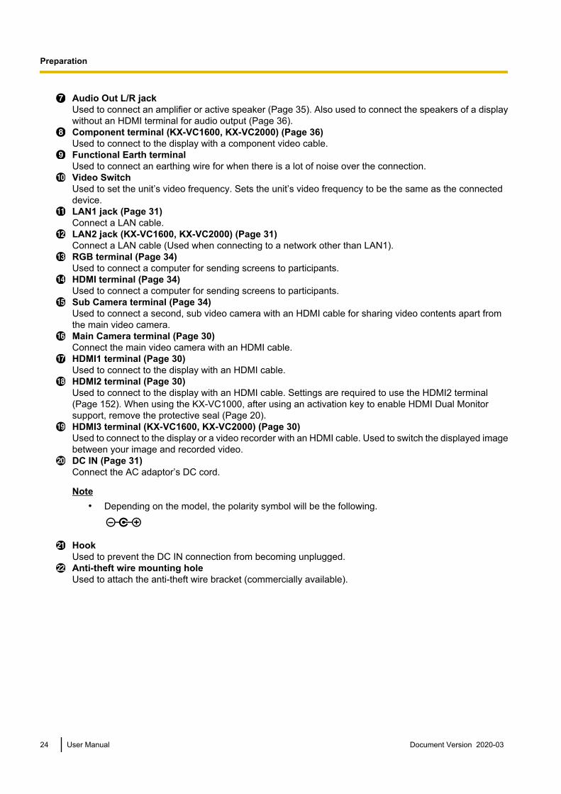
Audio Out L/R jackUsed to connect an amplifier or active speaker (Page 35). Also used to connect the speakers of a displaywithout an HDMI terminal for audio output (Page 36).Component terminal (KX-VC1600, KX-VC2000) (Page 36)Used to connect to the display with a component video cable.Functional Earth terminalUsed to connect an earthing wire for when there is a lot of noise over the connection.Video SwitchUsed to set the unit’s video frequency. Sets the unit’s video frequency to be the same as the connecteddevice.LAN1 jack (Page 31)Connect a LAN cable.LAN2 jack (KX-VC1600, KX-VC2000) (Page 31)Connect a LAN cable (Used when connecting to a network other than LAN1).RGB terminal (Page 34)Used to connect a computer for sending screens to participants.HDMI terminal (Page 34)Used to connect a computer for sending screens to participants.Sub Camera terminal (Page 34)Used to connect a second, sub video camera with an HDMI cable for sharing video contents apart fromthe main video camera.Main Camera terminal (Page 30)Connect the main video camera with an HDMI cable.HDMI1 terminal (Page 30)Used to connect to the display with an HDMI cable.HDMI2 terminal (Page 30)Used to connect to the display with an HDMI cable. Settings are required to use the HDMI2 terminal(Page 152). When using the KX-VC1000, after using an activation key to enable HDMI Dual Monitorsupport, remove the protective seal (Page 20).HDMI3 terminal (KX-VC1600, KX-VC2000) (Page 30)Used to connect to the display or a video recorder with an HDMI cable. Used to switch the displayed imagebetween your image and recorded video.DC IN (Page 31)Connect the AC adaptor’s DC cord.
Note• Depending on the model, the polarity symbol will be the following.
HookUsed to prevent the DC IN connection from becoming unplugged.Anti-theft wire mounting holeUsed to attach the anti-theft wire bracket (commercially available).
24 User Manual Document Version 2020-03
Preparation

Remote Control
A
B
C
E
H
I
J
D
K
L
M
N
O
P
Q
R
S
T
G
F
Press to enter screen standby mode (Page 27). The power of the unit can be turned on/off by pressingand holding (for 1 second). During communication, the power of the main unit cannot be turned off.Press to show your computer’s screen on your and the other party’s display during a video conference call.When not on a video conference call, the computer screen is shown on your display only (Page 90).Press to display the Menu screen (Page 44).Press to show the sub video camera’s images on your and the other party’s display during a videoconference call. When not on a video conference call, the sub video camera’s images are shown on yourdisplay only (Page 90).Press to display the Home screen (Page 41).Press to move the cursor, control the PT (Pan/Tilt) of a video camera, and select items.Press to make or manually answer video conference calls (Page 51, Page 63).Press to select the feature assigned to each colour. Available features are displayed in the guide area(Page 43).Press to adjust the volume during a video conference call. Press [+] to increase and [–] to decrease thevolume (Page 86).Press to mute the microphone during a video conference call, so that the other party cannot hear yourvoice (Page 87).Press to dial or perform settings where inputting digits/characters is required (Page 196).Press to display the connection status of the network and peripheral devices (Page 105).Press to show/hide on-screen information, such as the guide area, on the Home screen and the videoconference call screen (Page 45).Press to change the layout of the screen during a video conference call (Page 72).Press to return to the main video camera after showing images from a computer or sub video camera(Page 90).
Document Version 2020-03 User Manual 25
Preparation

Press to return to the previous screen.Press to confirm the selected item or entered information.Press to end a video conference call.Press to display the camera control screen (Page 94).Press for zoom control (zoom in/out) of the video camera either at your end or the other party’s end(Page 93).
26 User Manual Document Version 2020-03
Preparation

LED IndicationLEDs indicate the operational status of the unit, as follows:
PowerLED Status LED Status
Off Off • AC power: OFF (Without power suppliedfrom the AC adaptor)
Red on Off • AC power: ON (Power button: OFF)
Greenflashing
Blue flashing • Starting up
Redflashing
Off • A hardware fault has occurred.
Green onBlue flashing • Startup state
• Idle state
Green on Blue on • In a video conference call
Green on Yellow on • Self diagnosis is being performed.
Green onRed on • An error has occurred.
• Maintenance is being performed.• Software update in progress
Green on Red flashing • A serious error has occurred.
Red on Red flashing • The CPU cooling fan has stopped (KX-VC2000 only).
Green on Off • In screen standby mode
Screen StandbyWhen there is no video conference call transmission, and the remote control is not operated for more than 10minutes (default), or when the remote control’s [STANDBY] button is pressed, the unit enters screen standbymode. Video out to the display is suspended and the status LED turns off.Screen standby mode ends when the remote control is operated, or when a video conference call is received.
Notice• If screen standby mode ends and no image is visible, check to see if the display or video camera’s
power saving settings are enabled. Check each device’s manual for more information about its powersaving settings.
Note• You can change the length of time until the unit enters screen standby mode (Page 130).• The unit will not enter screen standby mode while displaying a computer’s screen or a sub video
camera’s image, even if the remote control is not operated for a period of time.• When the remote control is operated and screen standby mode ends, the Home screen will be
displayed.• If a button is pressed on the remote control to end screen standby mode, that button’s operation is not
performed in that case.• If screen standby mode begins while editing information in the contact list or other screen, any unsaved
changes will be lost.
Document Version 2020-03 User Manual 27
Preparation

• It takes about 7 seconds to return from screen standby mode. (The length of time may vary dependingon the type of display you are using.)
• The unit will not enter screen standby mode during USB recording, USB Device Mode, and Web HybridMode.
28 User Manual Document Version 2020-03
Preparation

Connection andPreparation
Device and Network ConnectionIn addition to the unit, you will need a video camera, adisplay, a microphone (Boundary Microphone orgeneral-purpose microphone) and connection cablesfor visual communication.Apart from the Boundary Microphone, the other devicesmust meet the following conditions:
Device Condition
VideoCamera
HDMI output required (resolution:1080p/1080i/720p)
Display*1 HDMI/component input requiredMake sure that the videofrequencies of the unit and displaymatch.
General-purposemicrophone
Line level output required (In case ofmicrophone level output,microphone amplifier also required)
*1 If displays are connected using both the HDMI terminal andComponent terminal, connect to displays that have the sameresolution (Page 153).
CablesPrepare the following commercially available cables:HDMI cable:
Category 2 (high speed) recommended
Note• Use cables with the HDMI logo (certified
HDMI cables) for HDMI connection. Usingnon-certified cables may adversely affectoperation. Use HDMI cables with secureconnectors.
LAN cable:1000BASE-T/100BASE-TX/10BASE-T (full duplex)Category 5 or greater
VGA cable (for computer connection when usingthe secondary video source):
15-pin mini D-Sub
Note• Ensure that the cables match the sockets of
both the unit and your computer.
Stereo pin plug cable (for connecting ageneral-purpose microphone/amplifier/activespeaker/display [without an HDMI terminal and withspeakers]):
RCA plug
Network EnvironmentWhen using the unit over the Internet, a broadbandconnection is required.
Document Version 2020-03 User Manual 29
Preparation
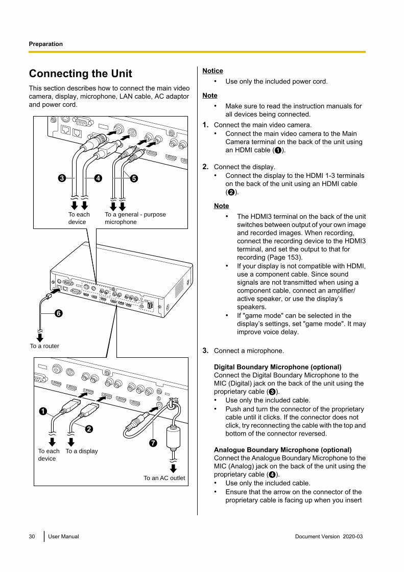
Connecting the UnitThis section describes how to connect the main videocamera, display, microphone, LAN cable, AC adaptorand power cord.
EDC
A
B
G
To each device
To each device
To a display
To an AC outlet
To a general - purpose microphone
F
To a router
Notice• Use only the included power cord.
Note• Make sure to read the instruction manuals for
all devices being connected.1. Connect the main video camera.
• Connect the main video camera to the MainCamera terminal on the back of the unit usingan HDMI cable (A).
2. Connect the display.• Connect the display to the HDMI 1-3 terminals
on the back of the unit using an HDMI cable(B).
Note• The HDMI3 terminal on the back of the unit
switches between output of your own imageand recorded images. When recording,connect the recording device to the HDMI3terminal, and set the output to that forrecording (Page 153).
• If your display is not compatible with HDMI,use a component cable. Since soundsignals are not transmitted when using acomponent cable, connect an amplifier/active speaker, or use the display’sspeakers.
• If "game mode" can be selected in thedisplay’s settings, set "game mode". It mayimprove voice delay.
3. Connect a microphone.
Digital Boundary Microphone (optional)Connect the Digital Boundary Microphone to theMIC (Digital) jack on the back of the unit using theproprietary cable (C).• Use only the included cable.• Push and turn the connector of the proprietary
cable until it clicks. If the connector does notclick, try reconnecting the cable with the top andbottom of the connector reversed.
Analogue Boundary Microphone (optional)Connect the Analogue Boundary Microphone to theMIC (Analog) jack on the back of the unit using theproprietary cable (D).• Use only the included cable.• Ensure that the arrow on the connector of the
proprietary cable is facing up when you insert
30 User Manual Document Version 2020-03
Preparation

the cable. When you disconnect the cable, gripthe connector securely and pull it out.
General-purpose microphoneConnect the microphone to the Audio In L/R jack onthe back of the unit using the stereo pin plug cable(E) after amplifying the signal to line level using adevice such as a microphone amplifier.• Connect the microphone correctly, as follows:
– Left channel ® L– Right channel ® R
Note• When connecting both the Boundary
Microphone and a general-purposemicrophone, both microphones can be usedsimultaneously.
• When connecting a headset, refer to"Headset Connection (Page 34)".
4. Connect to the network.• Connect a hub/router to the LAN jack on the
back of the unit using a category 5 or greaterLAN cable (F).
Note• Set the hub/router to Auto Negotiation
mode.• Do not connect to a hub/router set to Half
Duplex.• For more details about routers and DCEs,
refer to the documentation for each device.
5. Connect the power cord to the AC adaptor.• Use only the power cord included with the unit.
6. Insert the AC adaptor’s DC cord (G) into the DC INterminal on the back of the unit.• Use only the AC adaptor included with the unit.• Wrap the DC cord around the hook to prevent it
from being disconnected.
7. Plug in the power cord into the power outlet.• Choose an outlet that is convenient for
plugging/unplugging.
System Layout ExamplesDisplay and Main Video CameraPlace the display and main video camera at the sameside of the room.
Note• If you use speakers, refer to "Amplifier/Active
Speaker Connection" (Page 35).
Digital Boundary MicrophonesUp to 4 Digital Boundary Microphones can beconnected in cascade. There are no separate terminalsfor input and output on the Boundary Microphones.Also, an Analogue Boundary Microphone andgeneral-purpose microphones can be usedsimultaneously.
Note• Make sure that the microphones are placed at
least 1 m (3.3 ft) away from the display andspeakers.
Document Version 2020-03 User Manual 31
Preparation

• Do not connect more than 4 Digital BoundaryMicrophones. Doing so will cause all DigitalBoundary Microphones to stop working. If anAnalogue Boundary Microphone is alsoconnected, all audio input from the AnalogueBoundary Microphone will also stop working.
• If both of the following conditions are met, theoutput sent to the other party will be stereo;otherwise, monaural:– The bandwidth is higher than approximately
1.8 Mbps in a 2-party video conference callwith the HD Visual Communication Unit.
– The MIC position is set automatically ormanually to collect a sound in stereo.
• If a headset is connected, audio from theheadset microphone is given priority, and audiofrom Digital Boundary Microphones is no longerpicked up.
The range of each microphone (the radius of the circlewith a microphone at the centre) varies according to thelevel of surrounding and the number of microphonesbeing used. Place microphones accordingly, referringto the following table.
Noiselevel/
Micro–phone
A quietroom (40dBsplA)
A regularroom (45dBsplA)
A noisyroom (50dBsplA)
1
approx.3 m
(approx.9.8 ft)
approx.2.2 m
(approx.7.2 ft)
approx.1.2 m
(approx.3.9 ft)
2
approx.2.8 m
(approx.9.2 ft)
approx.1.5 m
(approx.4.9 ft)
approx.1 m
(approx.3.3 ft)
3
approx.2.3 m
(approx.7.5 ft)
approx.1.3 m
(approx.4.3 ft)
—
4
approx.2 m
(approx.6.5 ft)
approx.1.1 m
(approx.3.6 ft)
—
Layout examples (a regular room)(the grey circle indicates the microphone’s range):
Display
Microphone
4 m(13.1 ft)
4 m(13.1 ft)
Microphone
Display
4 m(13.1 ft)
Microphone
Microphone
Microphone
Microphone
4 m(13.1 ft)
4 m(13.1 ft)
4 m(13.1 ft)
Display
32 User Manual Document Version 2020-03
Preparation

Microphone Microphone
Microphone Microphone
4 m(13.1 ft)
4 m(13.1 ft)
4 m(13.1 ft)
4 m(13.1 ft) Display
Analogue Boundary MicrophonesYou can connect 1 Analogue Boundary Microphone.Together with Digital Boundary Microphones, up to 5boundary microphones can be connected.
Note• Make sure that the microphone is placed at
least 1 m (3.3 ft) away from the display andspeakers.
• Make sure that the microphone is placed withits connector facing the display.
• If both of the following conditions are met, theoutput sent to the other party will be stereo;otherwise, monaural:– The bandwidth is higher than approximately
1.8 Mbps in a 2-party video conference callwith the HD Visual Communication Unit.
– You are not using Digital BoundaryMicrophones and an Analogue BoundaryMicrophone together.
• If a headset is connected, audio from theheadset microphone is given priority, and audiofrom Analogue Boundary Microphones is nolonger picked up.
The range of the microphone (the radius of the circlewith a microphone at the centre) varies according to thelevel of surrounding noise. Place the microphoneaccordingly, referring to the following table.
Noiselevel/
Micro–phone
A quietroom(40
dBsplA)
A regularroom(45
dBsplA)
A noisyroom(50
dBsplA)
1
approx.2 m
(approx.6.5 ft)
approx.1.5 m
(approx.4.9 ft)
approx.1 m
(approx.3.3 ft)
Document Version 2020-03 User Manual 33
Preparation

Headset ConnectionYou can connect a headset to the headset jack on thefront of the unit.
AB
Headset
Note• Check the headphone connector (A) and the
microphone connector (B), and then connectthe headset.
• If a Boundary Microphone and a headset areconnected at the same time, audio from theheadset microphone is given priority, and audiofrom Boundary Microphones is no longer pickedup.
• If a general-purpose microphone and a headsetare connected at the same time, audio fromboth sources is picked up.
• If a headset is connected, audio will not beplayed through the display or speakers.
• When using HDMI3 as a video/audio recordingterminal, audio will be output even when aheadset is connected. (KX-VC1600,KX-VC2000)
• For 3-conductor stereo mini-plugs only.
Sub Video Camera ConnectionThis section describes how to connect a sub videocamera. You can transmit images taken with the subvideo camera to all parties.1. Connect the sub video camera.
• Connect the sub video camera to the SubCamera terminal on the back of the unit usingan HDMI cable.
Note• You can connect/disconnect the sub video
camera during a video conference call.
Computer ConnectionThis section describes how to connect a computer.Connecting a computer allows you to show thecomputer screen’s images on the display and transmitthem to other parties.You can transmit the computer’s images to all parties.1. Connect the computer.
• Connect the computer to the HDMI terminal onthe back of the unit using an HDMI cable.
34 User Manual Document Version 2020-03
Preparation

• For computers without HDMI ports, connect thecomputer to the RGB terminal on the back of theunit using a VGA cable.
Note• You can connect/disconnect the computer
during a video conference call.• One of the following resolutions is required
for transmitting computer images: VGA(640 ´ 480), SVGA (800 ´ 600), XGA(1024 ´ 768), HD (1280 ´ 720), WXGA(1280 ´ 768, 1280 ´ 800), SXGA(1280 ´ 1024), FWXGA (1360 ´ 768,1366 ´ 768), WXGA+ (1440 ´ 900), WXGA++ (1600 ´ 900), UXGA (1600 ´ 1200),WSXGA + (1680 ´ 1050), Full-HD(1920 ´ 1080).
• If both HDMI and VGA cables areconnected to the unit, the image of thecomputer connected using an HDMI cablewill be displayed.
Amplifier/Active SpeakerConnectionThis section describes how to connect an amplifier/active speaker.
1. Connect the amplifier/active speaker to the AudioOut L/R jack on the back of the unit using a stereopin plug cable.
Note• Connect the amplifier/active speaker
correctly, as follows:– Left channel ® L– Right channel ® R
• For more details about the amplifier oractive speaker, refer to the documentationfor the corresponding device.
Layout example:Place the speakers either side of the display, as follows:
MicrophoneMain video camera
Display
Speaker
Speaker
Notice• Place the speakers either side of the display. If
you place the display at the front of the roomand the speakers at the back, the microphone’sleft/right spatial direction may be reversed, andthe orientation of the image and sound will notmatch on the other party’s side.
Document Version 2020-03 User Manual 35
Preparation

Connecting the Display with aComponent CableIf your display does not have an HDMI terminal, use acomponent cable for connection.
1. Connect the display to the Component terminal onthe back of the unit using a component cable.
Note• To use the display’s speakers to output audio,
connect the display to the Audio Out L/R jack(Page 24) on the back of the unit using a stereopin plug cable.
• If displays are connected using both the HDMIterminal and Component terminal, connect todisplays that have the same resolution.
36 User Manual Document Version 2020-03
Preparation

Network Configuration ExampleDiagram (when using the Internet/KX-VC Series NAT Traversal Service)Compatible with LAN1
Router
Router
Router
LAN1
Internet
KX-VC Series NAT
Traversal Service
Document Version 2020-03 User Manual 37
Preparation

Diagram (when using an intranet/KX-VC Series NAT Traversal Service)Compatible with LAN1 and LAN2 (KX-VC1600, KX-VC2000)
Intranet
LAN2 LAN1
Router
Router
KX-VC Series
NAT Traversal
Service
Internet
Router
NoteWhen using a dual network (LAN1 and LAN2)• Use LAN1 when using KX-VC Series NAT Traversal Service.• The default gateway is in LAN1.• NAT or DHCP can be used only in LAN1.
38 User Manual Document Version 2020-03
Preparation

Preparing the Remote ControlInserting Batteries1. Open the cover.
2. Insert batteries (R6/LR6 [AA] dry cell*1), minus side first, then close the cover.
*1 R6 [AA] dry cell : KX-VC1000, KX-VC1300, KX-VC1600, KX-VC2000, KX-VC1300A, KX-VC1600ALR6 [AA] dry cell : KX-VC1000SX, KX-VC1300SX, KX-VC1600SX, KX-VC2000SX
Document Version 2020-03 User Manual 39
Preparation

Turning the Power On/OffNote
• Make sure that peripheral devices (e.g., display, main video camera) are turned on.• When you turn the power on for the first time, the Initial Settings screen is displayed (Page 48).• If the power is turned off by pulling out the AC adaptor when the Power LED is green, when the AC
adaptor is inserted and power is supplied again, the status will go back that of when the power is turnedon (the Power LED is green).
• The power can be turned on or off automatically (Page 156).
1 Press the Power button on the front of the unit or on theremote control for more than 1 second. (Both can turnthe power on or off.)• When the power is turned on, the Power LED starts
flashing green. Then, the Power LED becomesgreen, the Status LED starts flashing blue slowly,and the Home screen is displayed.
• When the power is turned off, the Power LEDbecomes red.
1
40 User Manual Document Version 2020-03
Preparation

Screen Display
Home Screen (Idle Screen)Displayed when the power is turned on. Also displayed when the [HOME] button is pressed on the remotecontrol.
A
B
DF
E
CG
Main Video Camera ImageDisplays the video from the main video camera.Unit InformationThe information displayed differs depending on the selected connection mode (Page 146).
IP Mode: The connection mode, local site name, the SIP user name (if using a SIP server)/H.323 extension,H.323 name (if using a gatekeeper), LAN1 IP address, LAN2 IP address (KX-VC1600, KX-VC2000),maximum bandwidth, encryption status indication icons, Static NAT status indication icon (if using the StaticNAT feature), Local Camera Display of MCU Site icon, Profile standby icon, and Incoming Call from anon-regist. icon.
NAT Traversal Mode: The connection mode, local site name, Terminal ID, maximum bandwidth, encryptionstatus indication icons, Local Camera Display of MCU Site icon, Profile standby icon, and Incoming Callfrom a non-regist. icon.
IP/NAT Traversal Mode: The connection mode, local site name, Terminal ID, LAN1 IP address, LAN2 IPaddress (KX-VC1600, KX-VC2000), maximum bandwidth, encryption status indication icons, Static NATstatus indication icon (if using the Static NAT feature), Local Camera Display of MCU Site icon, Profilestandby icon, and Incoming Call from a non-regist. icon.
Note• When selecting a local site (Page 115), the selected local site’s information is displayed. The local
site’s set device name is displayed. The information displayed differs depending on the local site’sconnection mode.
• If the local site name, SIP user name, H.323 extension, or H.323 name is too long to display, it willbe shortened and ended with "...".
Document Version 2020-03 User Manual 41
Preparation

Encryption Status Indication IconsThe status of the encryption settings for SIP/H.323/NAT Traversal is indicated by icons. The icon changesas follows:
Icon Status of Settings
When using IP mode: "SIP" is set to "ON" and "Encryption (SIP)" is set to"ON".
When using NAT Traversal mode or IP/NAT Traversal mode: "Encryption (SIP)" is set to "ON".
When using IP mode: "SIP" is set to "ON" and "Encryption (SIP)" is set to"OFF".
When using NAT Traversal mode or IP/NAT Traversal mode: "Encryption (SIP)" is set to "OFF".
"H.323" is set to "ON" and "Encryption (H.323)" is set to "Best effort".
"H.323" is set to "ON" and "Encryption (H.323)" is set to "ON".
"H.323" is set to "ON" and "Encryption (H.323)" is set to "OFF".
When using NAT Traversal mode or IP/NAT Traversal mode: "Encryption (NATTraversal)" is set to "ON".
When using NAT Traversal mode or IP/NAT Traversal mode: "Encryption (NATTraversal)" is set to "OFF".
Static NAT Status Indication Icon
Icon Status of Settings
When using IP mode, "Static NAT" is set to "ON".
Local Camera Display of MCU Site Icon
Icon Status of Settings
"Local Camera Display of MCU Site" is set to "OFF".
42 User Manual Document Version 2020-03
Preparation

Profile standby Icon
Icon Status of Settings
Profile standby is set (page 114).
Incoming Call from a non-regist. Icon
Icon Status of Settings
"Incoming Call from a non-regist." is set to "OFF" (page 150).
Group/SiteDisplays the name/group name assigned to One-Touch Connection number 1 through 5. If the name istoo long to display, it will be shortened and ended with "...".Remote Control IDDisplays the remote control ID of the unit when it is set (Page 132).Shortcut keyDisplays shortcut keys for accessing system settings (Page 157).Status IndicationThe status of the unit is indicated by icons.
Icon Status
Microphone is muted.
Network, server (any kind), or peripheral connection error (no connection, device error,etc.).
Note• If there are no connections, or there is a device error in other devices such as the
LAN cable, the icon will be displayed.
Note• If you set "Active Home Menu" to "OFF" in the administrator menu, you can hide BCDE
(Page 155). When hidden, you can unhide them again by pressing [FULL SCREEN] on the remotecontrol.
Icon Display AreaThe status of the unit is indicated by icons.
Icon Status
Displayed when recording (Page 83, Page 134).
Displayed during USB Device Mode (Page 135, Page 190).
Document Version 2020-03 User Manual 43
Preparation

Icon Status
Displayed during Web Hybrid Mode (Page 136, Page 192).
Menu Screen (Idle Screen)Displayed when [MENU] is pressed on the remote control. Displays operations you can perform and settingsyou can change.
A
B C
Menu ListDisplays the various functions you can use and settings available to change.GuideDisplays operations you can perform with the remote control when performing features or changingsettings.Administrator loginPress [Y] to display the administrator login screen for performing administrator settings. Depending on thesettings, "Admin Login" can be hidden and [Y] can be disabled (page 156).
44 User Manual Document Version 2020-03
Preparation

Video Conference Call ScreenA B
G
F
C
E
D
Other party’s informationWhen using IP mode:When registered in the contact list: The other party’s name/IP address is displayed.When not registered in the contact list: The other party’s IP address, SIP URI (SIP user name@SIP domainname), host name (e.g., hdvc.example.com), H.323 extension, H.323 name, MCU’s conference roomnumber@IP address, or MCU’s SIP user name@IP address is displayed. If the other party uses the sameSIP domain as you, only the SIP user name, and not the SIP URI, is displayed.
When using NAT Traversal Mode:• When registered in the contact list: The other party’s name/connection number is displayed.• When not registered in the contact list: The other party’s connection number is displayed.Video ImageDisplays the other party’s video, your own video, or video from the secondary video input such as acomputer display or a sub video camera.SubscreenDepending on the screen layout, your own video or the other party’s video is displayed here.DurationDisplays the duration of the current video conference call.
Note• 99h59m is displayed for the duration even if the length of the video conference call exceeds 100
hours.GuideDisplays operations you can perform with the remote control.Icon Display AreaNetwork Status IndicationThe number of antennas in the icon indicates differing levels of network congestion.The icon changes as follows:0 bars ( ): The network is very congested or the bandwidth is insufficient at the connection point.
1 bar ( ): The network is congested.
2 bars ( ): The network is slightly congested.
3 bars ( ): The network is not congested.
Document Version 2020-03 User Manual 45
Preparation

Note• If the icon shows only 0–1 bars continuously, contact your network administrator.• During multiple-party video conference calls, the icon is displayed on each site screen, but not on
your own image.• You can set whether to display the icon (Page 125). Regardless of icon display settings, the icon
is not displayed while the combined computer/video feed screen is being displayed.
Other Site’s Audio Indication ( )
Displayed on the Main Site when "Other Site's Audio" is set to "Mute" during a multiple-party videoconference call using the built-in MCU (Page 82, Page 110).Dialling Indication ( )Displayed when a call is incoming at another site, such as when a site is added during a call or when a callis made (Page 67).Presentation Mode Indication ( )Displayed for the main site for video conference calls with multiple connections that use an internal MCUwhen MCU mode is Presentation Mode (Page 78, Page 110, Page 126).Recording icon ( )Displayed when recording (Page 83, Page 134).Web Hybrid Mode icon ( )Displayed during Web Hybrid Mode (Page 136, Page 192).Status IndicationThe status of the unit is indicated by icons (Page 43).
Note• Pressing [FULL SCREEN] on the remote control will hide or unhide the other party’s information,
duration, icon display area*1, and guide displays.• If a black line is displayed on the left of a site in the dialogue box for site selection during a call, it
indicates that the site has the lowest bandwidth. If there are two types of communication groups dueto "Secondary Bandwidth Selection" (Page 129), a black line is displayed on the site with the lowestbandwidth for each group.Example: when Paris has the lowest bandwidth
*1 If the icons in the icon display area have been set to not be displayed, pressing [FULL SCREEN] will not show the icon.
46 User Manual Document Version 2020-03
Preparation

Entering charactersYou can use the remote control to input letters and numbers.• Note the following regarding entering the address of the other party.
– SIP user name/MCU’s conference room number: alphanumeric characters, symbols . = * + _ - $ ! ? /( ) ' (up to 60 characters)
– H.323 name: alphanumeric characters, symbols . @ : ; = * + # _ - $ \ % ^ ! ? / ` ( ) [ ] {|} ' (up to 60characters)
– SIP domain name: alphanumeric characters, symbols . - (up to 128 characters)– H.323 extension: numeric characters, symbols * # (up to 20 characters)
• For host names in the format of user name@domain name, characters and the number of characters thatcan be entered for user name and domain name are the same as for SIP user name and SIP domain name.
• The following characters can be used for input such as entering addresses in the contact list or directlyentering the address of the party to call.– When using SIP: alphanumeric characters, symbols . @ : = * + _ - $ ! ? / ( ) ' (up to 189 characters)– When using H.323: alphanumeric characters, symbols . @ : ; = * + # _ - $ \ % ^ ! ? / ` ( ) [ ] {|} '
(up to 189 characters)When using SIP, the user name (portion before the @ mark) can be up to 60 characters, and the domainname (portion after the @ mark) can be up to 128 characters.
• Enter values that comply with the corresponding standard. For details, contact your network administrator.
About IPv6 Addresses• When manually setting an IPv6 address, it may be entered in its shortened form or unshortened form
(Page 196).(Input example)2001:db8::102001:0db8::00102001:db8:0:0:0:0:0:102001:0db8:0000:0000:0000:0000:0000:0010
Document Version 2020-03 User Manual 47
Preparation
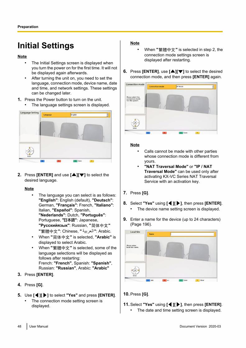
Initial SettingsNote
• The Initial Settings screen is displayed whenyou turn the power on for the first time. It will notbe displayed again afterwards.
• After turning the unit on, you need to set thelanguage, connection mode, device name, dateand time, and network settings. These settingscan be changed later.
1. Press the Power button to turn on the unit.• The language settings screen is displayed.
2. Press [ENTER] and use [ ][ ] to select thedesired language.
Note• The language you can select is as follows:
"English": English (default), "Deutsch":German, "Français": French, "Italiano":Italian, "Español": Spanish,"Nederlands": Dutch, "Português":Portuguese, " ": Japanese,"Русскийязык": Russian, " "" ": Chinese, " ": Arabic.
• When " " is selected, "Arabic" isdisplayed to select Arabic.
• When " " is selected, some of thelanguage selections will be displayed asfollows after restarting:French: "French", Spanish: "Spanish",Russian: "Russian", Arabic: "Arabic"
3. Press [ENTER].
4. Press [G].
5. Use [ ][ ] to select "Yes" and press [ENTER].• The connection mode setting screen is
displayed.
Note• When " " is selected in step 2, the
connection mode settings screen isdisplayed after restarting.
6. Press [ENTER], use [ ][ ] to select the desiredconnection mode, and then press [ENTER] again.
Note• Calls cannot be made with other parties
whose connection mode is different fromyours.
• "NAT Traversal Mode" or "IP / NATTraversal Mode" can be used only afteractivating KX-VC Series NAT TraversalService with an activation key.
7. Press [G].
8. Select "Yes" using [ ][ ], then press [ENTER].• The device name setting screen is displayed.
9. Enter a name for the device (up to 24 characters)(Page 196).
10. Press [G].
11. Select "Yes" using [ ][ ], then press [ENTER].• The date and time setting screen is displayed.
48 User Manual Document Version 2020-03
Preparation

12. Select the item using [ ][ ], then inputinformation.• Enter the year (4 digits), month (1–2 digits), day
(1–2 digits), time (24 hour display), and selectthe date format (Month/Day/Year, Day/Month/Year, Year/Month/Day) and the hour displayformat (12h/24h).
13. Press [G].
14. Select "Yes" using [ ][ ], then press [ENTER].• The network settings screen is displayed.
15. Use [ ][ ] to select the following items for input:
Note• For the KX-VC1000 and KX-VC1300, "IP
Address (LAN 1)" (setting), "IP Address(LAN 1)", and "Subnet mask (LAN 1)" arerespectively displayed as "IPAddress" (setting), "IP Address", and"Subnet mask".
"IP Address (LAN 1)"(setting): Use [ ][ ] toselect whether the IP address information for thisunit ("IP Address (LAN 1)", "Subnet mask (LAN1)", "Default Gateway") will be obtainedautomatically from a DHCP server or will be setmanually.
– "Auto" (default): Obtain the IP addressinformation automatically.
– "Manual": Set the IP address informationmanually.
Note• Even if you have selected "Auto", you still
may not be able to acquire an IP addressdue to problems such as networkcongestion. In this case, "Address is notassigned" is displayed in the upper right ofthe Home screen. Contact your networkadministrator.
"IP Address (LAN 1)": Enter the IP address of theunit."Subnet mask (LAN 1)": Enter the subnet mask."Default Gateway": Enter the IP address of thedefault gateway.
Note• "IP Address (LAN 1)", "Subnet mask
(LAN 1)", and "Default Gateway" can beentered only if "IP Address (LAN1)" (setting) is set to "Manual".
• If the value for "IP Address (LAN 1)","Subnet mask (LAN 1)", or "DefaultGateway" contains 1 or 2 digits numbers,enter these numbers as they are. Do notenter like [.001].Example: The IP address is [192.168.0.1].– Correct entry: [192.168.0.1]– Wrong entry: [192.168.000.001]
"DNS Server": Use [ ][ ] to select whether theIP address information for the DNS servers("Primary DNS Server", "Secondary DNSServer") will be obtained automatically from aDHCP server or will be set manually.– "Auto" (default): Obtain the IP address
information automatically.– "Manual": Set the IP address information
manually.
Note• To select "Auto", "IP Address (LAN
1)" (setting) must be set to "Auto".• The DNS server must be set to use KX-VC
Series NAT Traversal Service, to check forupgrades, and to download the latestsoftware from the network.
"Primary DNS Server": Enter the IP address of theprimary DNS server."Secondary DNS Server": Enter the IP address ofthe secondary DNS server.
Document Version 2020-03 User Manual 49
Preparation

Note• "Primary DNS Server" and "Secondary
DNS Server" can be entered only if "DNSServer" is set to "Manual".
• If the value for "Primary DNS Server" or"Secondary DNS Server" contains 1 or 2digits numbers, enter these numbers asthey are. Do not enter like [.001].Example: The IP address is [192.168.0.1].– Correct entry: [192.168.0.1]– Wrong entry: [192.168.000.001]
"LAN Mode (LAN 1)": Press [ENTER] and use[ ][ ] to select the LAN mode.– "1 Gbps (Auto)": Negotiates with the other
party to determine the LAN mode. Themaximum setting is 1 Gbps (full duplex).
– "1 Gbps (Fix)": Fixes the LAN mode to 1 Gbps(full duplex).
– "100 Mbps (Auto)" (default): Negotiates withthe other party to determine the LAN mode. Themaximum setting is 100 Mbps (full duplex).
– "100 Mbps (Fix)": Fixes the LAN mode to 100Mbps (full duplex).
– "10 Mbps (Fix)": Fixes the LAN mode to 10Mbps (full duplex).
Note• This setting is only displayed for the
KX-VC2000.• Match settings according to the hub or
router to be connected.• When "10 Mbps (Fix)" is set, set the "Max.
Bandwidth" of "Call set up" to 10 Mbps orlower (Page 124).
16. Press [G].
17. Select "Yes" using [ ][ ], then press [ENTER].• Settings become effective after the automatic
restart.
Note• If the IP address or subnet mask contains an
invalid value, a message will appear requiringyou to enter a valid IP address or subnet mask.
• A multicast address or broadcast addresscannot be used for the IP address.
• If the unit is turned off and restarted beforecompleting step 14, you must start again fromstep 1. If the unit is restarted after step 14 iscompleted, you can restart from step 15.
50 User Manual Document Version 2020-03
Preparation

Making a Video Conference CallYou can make a video conference call using one of the following methods.
Note• Make sure that peripheral devices (e.g., display, main video camera) are turned on.• If a called party does not answer a video conference call within approximately 60 seconds, the call will
be terminated automatically.• Only 2-party video conference calls can be made using the incoming call history.• The number of bars in the antenna icon will be 0 to indicate communication bandwidth that is lower
than 256 kbps per site. In such cases, the image and voice quality may deteriorate.• Video conference calls cannot be made if the call type programmed in the contact list (SIP or H.323)
has been set to "OFF" on the call type settings screen.• If a video conference call is made using a profile with an entry restriction, and you want to add a party
to that call, you cannot call the party by entering an address directly or by using the call history.• If a video conference call is received during another video conference call, a dialogue box is displayed
to confirm whether to answer the incoming video conference call.Use [ ][ ] to select "Yes" or "No" and press [ENTER].• Select "Yes" to answer the video conference call.• Select "No" to stop receiving the incoming video conference call and continue your current video
conference call.
Calling Using One-Touch Connection Numbers From the HomeScreen
Note• To call using one-touch connection numbers, you need to set them in advance (Page 129).
1 Press [HOME].• The Home screen is displayed.
1
3 4
2
2 With the dial keys, enter a One-Touch Connection number(1 to 5).• The information registered in the selected One-Touch
Connection number is displayed.
3 Press [START] to start the call.• You can also start the call pressing [ENTER].
4 When you want to end the call, press [END].• The Home screen is displayed.
Document Version 2020-03 User Manual 51
S
t
a
r
t
i
n
g
a
V
i
d
e
o
C
o
n
f
e
r
e
n
c
e
Starting a Video Conference
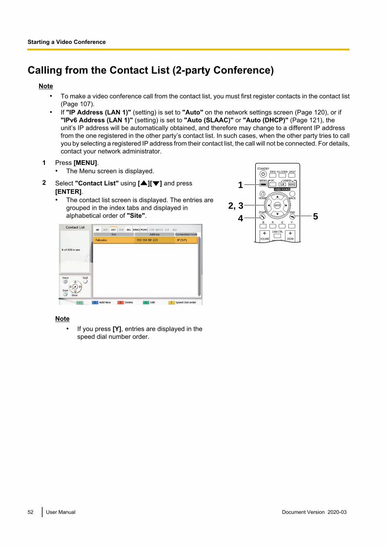
Calling from the Contact List (2-party Conference)Note
• To make a video conference call from the contact list, you must first register contacts in the contact list(Page 107).
• If "IP Address (LAN 1)" (setting) is set to "Auto" on the network settings screen (Page 120), or if"IPv6 Address (LAN 1)" (setting) is set to "Auto (SLAAC)" or "Auto (DHCP)" (Page 121), theunit’s IP address will be automatically obtained, and therefore may change to a different IP addressfrom the one registered in the other party’s contact list. In such cases, when the other party tries to callyou by selecting a registered IP address from their contact list, the call will not be connected. For details,contact your network administrator.
1 Press [MENU].• The Menu screen is displayed.
1
4 52, 3
2 Select "Contact List" using [ ][ ] and press[ENTER].• The contact list screen is displayed. The entries are
grouped in the index tabs and displayed inalphabetical order of "Site".
Note• If you press [Y], entries are displayed in the
speed dial number order.
52 User Manual Document Version 2020-03
Starting a Video Conference

3 Select the entry you want to call using [ ][ ].• You can switch the index tab back and forth using
[ ][ ]. (Index tabs in which no entries exist will beskipped.)
• Press a numeric button on the remote control toswitch to the index tab assigned to that button, asshown below.
Numeric button
1234567890
#
Index Tab
–ABCDEFGHIJKL
MNOPQRSTUV
WXYZ0-9-&!/
–
Note• If the display is sorted by speed dial number in
step 2, you can click a speed dial number (1through 600) to select it.
4 Press [START] to start the call.
5 When you want to end the call, press [END].• The Home screen is displayed.
Document Version 2020-03 User Manual 53
Starting a Video Conference

Calling Using Profile (Multiple-party Video Conference Calls)When making multiple-party video conference calls from the Menu screen, you can make a call using one of20 profiles (1 to 20).
Note• To use profiles with the KX-VC1000, you must use an activation key to enable 4 Point Built-in MCU
support (Page 20).• To call using a profile, you need to have a profile programmed in profile settings in advance
(Page 110).
1 Press [MENU].• The Menu screen is displayed.
1
4 52, 3
2 Select "Profile" using [ ][ ] and press [ENTER].• The profile list screen is displayed.
3 Select the profile you want to use to make a call using[ ][ ].
4 Press [START] to start the call.
5 When you want to end the call, press [END].• For ending a multiple-party video conference call,
refer to "Disconnecting Parties During VideoConference Call (Page 70)".
Note• You can make a video conference call by changing
the party of the selected profile before starting the callby pressing [START]. Be aware that the selectedconnection destination will not be saved.
54 User Manual Document Version 2020-03
Starting a Video Conference

1. Press [B].• The profile settings screen is displayed.
2. Select "Site" using [ ][ ], then press [ENTER].• The screen for selecting the party you want to
call from the profile is displayed.3. Select the party using [ ][ ], then press
[ENTER].• Selecting an item will add or remove the " "
mark for the item in the selection column. Thecontacts with a " " mark will be called.
4. Press [START] to start the call.• A dialogue box to confirm the start of a call is
displayed.5. Use [ ][ ] to select "Yes" and press [ENTER].
Document Version 2020-03 User Manual 55
Starting a Video Conference

Calling by Entering an Address DirectlyWhen using IP mode, you can make a video conference call by entering the IP address (or host name), SIPURI (or SIP user name), H.323 extension, H.323 name, or MCU’s conference room number@IP address.When using NAT Traversal mode, you can make a call by entering the connection number.
Note• When using a KX-VC1000 that has not been expanded for 4 Point Built-in MCU support, one connection
can be established, and "Connection mode", "Site", and "Outgoing Bandwidth" are displayed for"Connection mode 1", "Site 1", and "Outgoing Bandwidth / Site".
1 Press [MENU].• The Menu screen is displayed.
1
9 10
2-5, 7-8
6
2 Select "Manual Dial" using [ ][ ] and press[ENTER].• The manual dial screen is displayed. (The screen is
from when using the KX-VC1600 (with standardfeatures).)
Note• You can display the manual dial screen by
pressing [START] in the Home screen insteadof performing steps 1 and 2.
3 Use [ ][ ] to select the connection mode you want toinput ("Connection mode 1" to "Connection mode3") and press [ENTER].
4 Use [ ][ ] to select the connection mode ("IP Mode (SIP)", "IP Mode (H.323)", "NAT Traversal Mode").
5 Use [ ][ ] to select the site ("Site 1" to "Site 3").
6 When using IP mode, enter the IP address (or hostname), SIP URI (or SIP user name), H.323 extension,H.323 name, or MCU’s conference room number@IPaddress. When using NAT Traversal mode, enter theconnection number (7 digits).
Note• When starting multiple-party video conference
calls, repeat steps 3-6.• When calling more than 4 parties, press [R] to
display the next page.
56 User Manual Document Version 2020-03
Starting a Video Conference
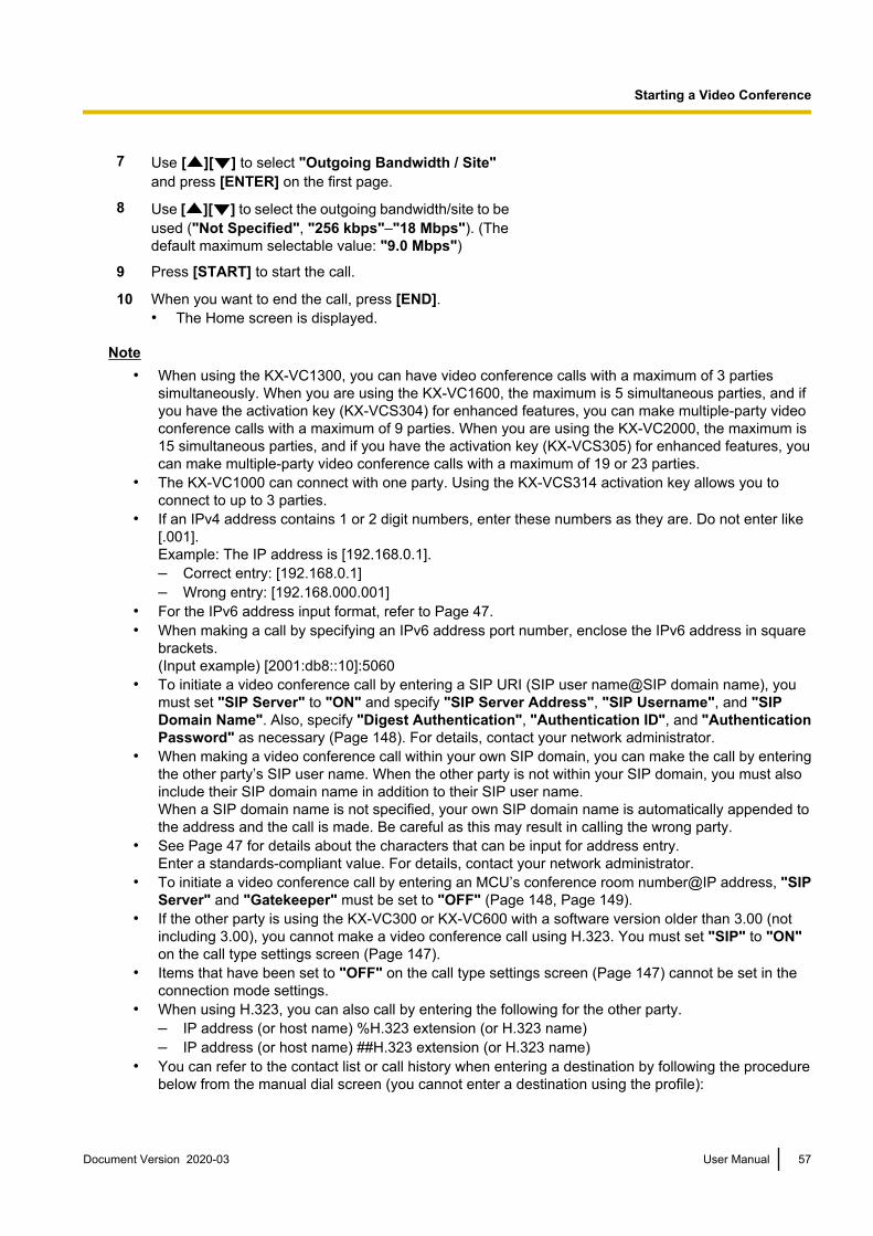
7 Use [ ][ ] to select "Outgoing Bandwidth / Site"and press [ENTER] on the first page.
8 Use [ ][ ] to select the outgoing bandwidth/site to beused ("Not Specified", "256 kbps"–"18 Mbps"). (Thedefault maximum selectable value: "9.0 Mbps")
9 Press [START] to start the call.
10 When you want to end the call, press [END].• The Home screen is displayed.
Note• When using the KX-VC1300, you can have video conference calls with a maximum of 3 parties
simultaneously. When you are using the KX-VC1600, the maximum is 5 simultaneous parties, and ifyou have the activation key (KX-VCS304) for enhanced features, you can make multiple-party videoconference calls with a maximum of 9 parties. When you are using the KX-VC2000, the maximum is15 simultaneous parties, and if you have the activation key (KX-VCS305) for enhanced features, youcan make multiple-party video conference calls with a maximum of 19 or 23 parties.
• The KX-VC1000 can connect with one party. Using the KX-VCS314 activation key allows you toconnect to up to 3 parties.
• If an IPv4 address contains 1 or 2 digit numbers, enter these numbers as they are. Do not enter like[.001].Example: The IP address is [192.168.0.1].– Correct entry: [192.168.0.1]– Wrong entry: [192.168.000.001]
• For the IPv6 address input format, refer to Page 47.• When making a call by specifying an IPv6 address port number, enclose the IPv6 address in square
brackets.(Input example) [2001:db8::10]:5060
• To initiate a video conference call by entering a SIP URI (SIP user name@SIP domain name), youmust set "SIP Server" to "ON" and specify "SIP Server Address", "SIP Username", and "SIPDomain Name". Also, specify "Digest Authentication", "Authentication ID", and "AuthenticationPassword" as necessary (Page 148). For details, contact your network administrator.
• When making a video conference call within your own SIP domain, you can make the call by enteringthe other party’s SIP user name. When the other party is not within your SIP domain, you must alsoinclude their SIP domain name in addition to their SIP user name.When a SIP domain name is not specified, your own SIP domain name is automatically appended tothe address and the call is made. Be careful as this may result in calling the wrong party.
• See Page 47 for details about the characters that can be input for address entry.Enter a standards-compliant value. For details, contact your network administrator.
• To initiate a video conference call by entering an MCU’s conference room number@IP address, "SIPServer" and "Gatekeeper" must be set to "OFF" (Page 148, Page 149).
• If the other party is using the KX-VC300 or KX-VC600 with a software version older than 3.00 (notincluding 3.00), you cannot make a video conference call using H.323. You must set "SIP" to "ON"on the call type settings screen (Page 147).
• Items that have been set to "OFF" on the call type settings screen (Page 147) cannot be set in theconnection mode settings.
• When using H.323, you can also call by entering the following for the other party.– IP address (or host name) %H.323 extension (or H.323 name)– IP address (or host name) ##H.323 extension (or H.323 name)
• You can refer to the contact list or call history when entering a destination by following the procedurebelow from the manual dial screen (you cannot enter a destination using the profile):
Document Version 2020-03 User Manual 57
Starting a Video Conference

When using IP mode: the IP address (or host name), SIP URI (or SIP user name), H.323 extension,H.323 name, or MCU’s conference room number@IP address
When using NAT Traversal mode: the connection number
1. Press [G].• A dialogue box to select either the contact list or call history is displayed.
2. Use [ ][ ] to select the contact list or call history, and then press [ENTER].3. Use [ ][ ] to select the contact you want to refer to.
• For the contact list, you can use [ ][ ] or the numeric buttons of the remote control to selectthe displayed tab (Page 53).
• For the call history, press [G] to switch between the incoming call history and the outgoing callhistory.
4. Press [ENTER].• When the called party was selected from the contact list, the site name for the other party is displayed.• When the called party was selected from the call history, selecting a contact by their displayed site
name in the history will display the site name for the other party.• For a party that is displaying a site name, the site name can be changed when inputting letters and
numbers directly by pressing [Y] to delete the site name and then input it.
58 User Manual Document Version 2020-03
Starting a Video Conference
Calling from the Call HistoryYou can make a video conference call from the call history. The call history is divided into outgoing and incomingcalls. The last 100 video conference calls made and received are stored in the outgoing and incoming callhistory. Information such as the contact name, group name, address information*1, the date and time, theduration of the call, the result of the call, and the connection mode is displayed for each call on the outgoingcall history screen and incoming call history screen. If the address of an entry in the call history is deleted fromor edited in the contact list, the contact name in the call history entry will be replaced by the address information.*1 Address information is as follows.
IP address/host name/SIP URI/H.323 extension/H.323 name/MCU’s conference room number@IP address/MCU’s SIP username@IP address/connection number. (When using NAT Traversal mode, the connection number is displayed.)
Note• If the other party uses the same SIP domain name as you, only the SIP user name, and not the SIP
URI (SIP user name@SIP domain name) will be displayed in the call history.
Outgoing Call History:• For video conference calls made using the contact list, the contact name is displayed. For video conference
calls made by entering the IP address (or host name)/SIP URI/H.323 extension/H.323 name/MCU’sconference room number@IP address/connection number directly (Page 56), that information is displayedinstead of the contact name. (That information is displayed even if a matching entry exists in the contactlist.)
• Even when a profile is used to make a video conference call, the call will appear in the outgoing call history.You can then make a video conference call with a profile from the outgoing call history.
• If consecutive video conference calls are made to the same destination, only the latest call will appear inthe outgoing call history.
Incoming Call History:• If the calling party’s IP address/SIP URI/H.323 extension/H.323 name/MCU’s conference room
number@IP address/connection number is registered in the contact list, the contact name/group name isdisplayed. Otherwise, the IP address (or host name)/SIP URI/H.323 extension/H.323 name/MCU’sconference room number@IP address/MCU’s SIP user name@IP address/connection number isdisplayed.
• Depending on the type of MCU, a video conference call may be received from the MCU’s SIP username@IP address rather than the MCU’s conference room number@IP address. In that case, you directlycannot call the MCU’s conference room from this incoming call history.
• If consecutive unanswered video conference calls are received from the same party, only the latest callwill appear in the incoming call history.
• When connecting to a non-Panasonic video conference system, you may not be able to initiate videoconference calls with SIP URIs (or SIP user names)/H.323 extension/H.323 name in the incoming callhistory. In this case, contact your network administrator.
Document Version 2020-03 User Manual 59
Starting a Video Conference

1 Press [MENU].• The Menu screen is displayed.
1
4, 5 62, 3
2 Select "Call History" using [ ][ ] and press[ENTER].• The outgoing call history screen is displayed.
60 User Manual Document Version 2020-03
Starting a Video Conference
Note• When calling using a profile or when a call is
received during Profile standby settings, the callis added to the outgoing and incoming callhistory between the parties, and a profile historyshowing the profile used is displayed. The ProfileID (PID) is displayed in the profile history and theindividual outgoing and incoming call historiesthat used the profile. However, when using aKX-VC1000 that has not been expanded for 4Point Built-in MCU support, the Profile ID (PID)column is not displayed.
• The result of the video conference call isdisplayed in the "Call result" column as follows:– : The video conference call was
established.– : The video conference call was not
established.– : The video conference call was made
using multicasting or a profile was used.• To move to the incoming call history screen,
press [G]. You can switch between the outgoingcall history screen and the incoming call historyscreen by pressing [G].
• In the incoming call history, if a party is notregistered in your contact list, the addressinformation received from the party is displayed.
• In the outgoing call history, if a party is registeredin your contact list, the contact name isdisplayed. However, when calling by entering anIP address (or host name), SIP URI (or SIP username), H.323 extension, H.323 name, or MCU’sconference room number@IP address/connection number (Page 56), even if the partyis registered in your contact list, the enteredinformation is displayed instead of the contactname.
• When a contact in the incoming call history isnewly added to your contact list, the incoming callhistory will be updated to display the contact’sinformation from the contact list.
• When a party that is not registered in your contactlist is selected, if you press [B], the contact listregistration screen will be displayed and a newcontact can be registered (Page 109). Also, youmay not be able to register a SIP URI (or SIP username), H.323 extension, or H.323 name from theincoming call history to the contact list forreasons such as non-compliance with therelevant standards. In this case, contact yournetwork administrator.
Document Version 2020-03 User Manual 61
Starting a Video Conference

3 Select the party you want to call using [ ][ ].
Note• If you press [ENTER], the call history details
screen is displayed. (Not displayed when theprofile history or multicast call history (outgoing)is selected.)
• When not selecting a local site (Page 115), thevalues of the basic settings are displayed for"Local site name".
• "Bandwidth" displays the mediated bandwidthfor connected sites.
• Depending on the other party, "Device type"may be blank.
• When using a KX-VC1000 that has not beenexpanded for 4 Point Built-in MCU support,"Profile ID" is not displayed.
4 Press [START].• The manual dial screen is displayed. (Not displayed
when the multicast history was selected.)
Note• You can change the number of sites called
or edit the other party’s address.
5 Press [START] to start the call.
6 When you want to end the call, press [END].• The Home screen is displayed.
62 User Manual Document Version 2020-03
Starting a Video Conference

Answering a Video Conference CallDepending on your setting, you can respond to a request to participate in a video conference call manually(manual answer), automatically (automatic answer), or forcibly (forced answer) (Page 123).
Note• Make sure that peripheral devices (e.g., display, main video camera) are turned on.• For sites operating as "Sub Sites" in multiple-party video conference calls using the Main Site’s built-in
MCU, for each Sub Site, set "More than one incoming call" to "OFF" in "Call set up". With thissetting, calls cannot be received during a video conference call.
When Manual Answer is SetWhen a video conference call is incoming there will be an incoming call ring, and a dialogue box is displayed.
When the caller is registered in the contact list, the caller’s siteis displayed.When the caller is not registered, the caller’s IP address,connection number or other caller information that is receivedis displayed.
Note• If the other party uses the same SIP domain name as you, only the SIP user name, and not the SIP
URI (SIP user name@SIP domain name) is displayed.• If the caller’s group/site name, host name, SIP URI (or SIP user name), H.323 extension, or H.323
name is too long to display, it will be shortened and ended with "...".
Operation1 Press [START].
• The video conference begins.• You can also answer the video
conference call by pressing [ENTER].
1
Document Version 2020-03 User Manual 63
Starting a Video Conference

Note• If you do not answer a video conference call within approximately 60 seconds, the call will be terminated
automatically.• If a video conference call is received while making a video conference call, a dialogue box to confirm
if you answer a video conference call is displayed (only when "More than one incoming call" is setto "ON" in "Call set up").Use [ ][ ] to select "Yes" or "No" and press [ENTER].– When "Yes" is selected, you can answer a video conference call.– When "No" is selected, you can stop receiving a video conference call and continue making a
video conference call.
When Automatic Answer is SetWhen a video conference call is incoming while the Home screen is displayed, the call will be automaticallyanswered after one ring, and transmission then begins. When a video conference call is incoming with a screenother than the Home screen displayed, a dialogue box is displayed, and the incoming calling continues.
Forced AnsweringWhen a video conference call is incoming, the call is automatically answered regardless of existing calls orwhile idle, and transmission then begins.
64 User Manual Document Version 2020-03
Starting a Video Conference
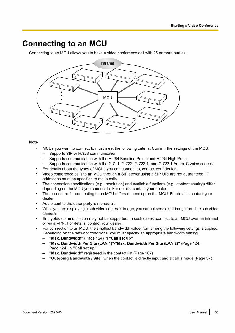
Connecting to an MCUConnecting to an MCU allows you to have a video conference call with 25 or more parties.
MCU
Intranet
Note• MCUs you want to connect to must meet the following criteria. Confirm the settings of the MCU.
– Supports SIP or H.323 communication– Supports communication with the H.264 Baseline Profile and H.264 High Profile– Supports communication with the G.711, G.722, G.722.1, and G.722.1 Annex C voice codecs
• For details about the types of MCUs you can connect to, contact your dealer.• Video conference calls to an MCU through a SIP server using a SIP URI are not guaranteed. IP
addresses must be specified to make calls.• The connection specifications (e.g., resolution) and available functions (e.g., content sharing) differ
depending on the MCU you connect to. For details, contact your dealer.• The procedure for connecting to an MCU differs depending on the MCU. For details, contact your
dealer.• Audio sent to the other party is monaural.• While you are displaying a sub video camera’s image, you cannot send a still image from the sub video
camera.• Encrypted communication may not be supported. In such cases, connect to an MCU over an intranet
or via a VPN. For details, contact your dealer.• For connection to an MCU, the smallest bandwidth value from among the following settings is applied.
Depending on the network conditions, you must specify an appropriate bandwidth setting.– "Max. Bandwidth" (Page 124) in "Call set up"– "Max. Bandwidth Per Site (LAN 1)"/"Max. Bandwidth Per Site (LAN 2)" (Page 124,
Page 124) in "Call set up"– "Max. Bandwidth" registered in the contact list (Page 107)– "Outgoing Bandwidth / Site" when the contact is directly input and a call is made (Page 57)
Document Version 2020-03 User Manual 65
Starting a Video Conference

Operating an MCU Remotely using Tone SignalsWhen connecting to an MCU, you can send tone signals by pressing buttons (0–9, #, or ) on the remotecontrol. Doing so allows you to operate (e.g., change the screen layout) the MCU remotely.
Note• Features and operations that can be performed
remotely will vary depending on the MCU.• If the MCU you are connecting to does not support
tone signals, an error message is displayed.• If the other party sends tone signals to you, sound
may be interrupted or a ringing noise may occur.• You can operate the other party’s device using tone
signals with the KX-VC2000, KX-VC1600,KX-VC1300, KX-VC1000 and HDVC-MPCS.
1
1 Enter a tone signal (0–9, #, or ).• The input field (A) is displayed.A
Note• The input field can only contain up to 16
characters. If you input 17 characters, the firstcharacter input will not be displayed in the inputfield but all tone signals will be sent.
• The input field is not displayed until a tone signalis entered.
• If a tone signal is not entered for about 3seconds, the input field disappears.
• If you enter further tone signals after the inputfield has disappeared, the tone signals enteredthe previous time are also displayed.
66 User Manual Document Version 2020-03
Starting a Video Conference

Adding Parties to an Existing Video Conference Call(Except Sub Sites)
A site in a 2-party video conference call or the Main Site can use the following operations to add parties to anexisting call.
Note• When using a KX-VC1000 that has not been expanded for 4 Point Built-in MCU support, "Make a
call" is not displayed and you cannot connect to another party during a video conference.
1. Press [MENU].• The communication menu screen is displayed.
2. Use [ ][ ][ ][ ] to select "Make a call" and press [ENTER].• A dialogue box to select a dialling method is displayed.
Note• For sites that are in a video conference call that was made using methods other than profile calling,
the dialogue box is not displayed, and the manual dial screen is displayed instead.• For sites that are in a video conference call that was made using profile calling with entry restriction
set to "ON" in the profile settings, the dialogue box is not displayed, and the profile used to makethe call is selected.
3. Use [ ][ ] to select the dialling method ("Profile" or "Manual Dial").
When selecting profile:• The site selection screen is displayed.
1. Select the site that you want to add using [ ][ ] and press [ENTER].• " " is displayed in the selection field.
Document Version 2020-03 User Manual 67
D
u
r
i
n
g
V
i
d
e
o
C
o
n
f
e
r
e
n
c
e
C
a
l
l
s
During Video Conference Calls

When selecting manual dial:• The manual dial screen is displayed. (The screen is from when using the KX-VC1600 (with standard
features).)
1. Program the information of the other party whom you want to add using [ ][ ].
Note• You can refer to the contact list or call history when entering the other party’s information.
Press [G].• A dialogue box to select either the contact list or call history is displayed.Use [ ][ ] to select the contact list or call history, and then press [ENTER].Use [ ][ ] to select the contact you want to refer to.• For the contact list, you can use [ ][ ] or the numeric buttons of the remote control to
select the displayed tab (Page 53).• For the call history, press [G] to switch between the incoming call history and the outgoing
call history.Press [ENTER].
4. Press [START].
Note• If your own site becomes a Sub Site, add additional sites to a video conference call by following the
procedure in "Adding Parties to an Existing Video Conference Call (Except Main Sites) (Page 69)".• When the called party was selected from the contact list, the site name for the other party is displayed.• When the called party was selected from the call history, selecting a contact by their displayed site
name in the history will display the site name for the other party.• For a party that is displaying a site name, the site name can be changed when inputting letters and
numbers directly by pressing [Y] to delete the site name and then enter it.• For information about the number of sites that can be connected to, refer to Page 57.
68 User Manual Document Version 2020-03
During Video Conference Calls

Adding Parties to an Existing Video Conference Call(Except Main Sites)
A sub site in a multi-party conference or a site in a 2-party video conference call can use the following operationsto add parties to an existing call.
Note• "Site" must be configured for profile settings of the main site (Page 112).• When the main site receives profile IDs from sub sites, the main site makes a call to the "Site"
corresponding to the ID.• When there is a 2-party video conference call, the site receiving the profile ID will become the main
site and make the call.• Main sites do not call using profiles corresponding to "Site". (Sites registered to "Site" are only used
as address lists and other profile settings are not used.)1. Press [#] [1] [X] [X] (XX: 01 to 20)
• The main site calls the site registered to "Site" in accordance with the profile ID (XX: 01 to 20).
Main site Sub site
#1xx
Call (Profile ID: XX)
Diagram
Note• Other parties cannot be added when "DTMF for Dial / Disconnect" in "MCU Settings" is set to
"OFF" for main sites (Page 129).• Different profile IDs can be set by repeating step 1 multiple times.• Multiple sub sites can set their profile IDs to a main site in step 1.• In the following situations, sites cannot be added from sub sites.
– Calls made from profiles– Calls started by profile settings according to the profile standby settings– While sharing contents with dual stream– While the main site is sharing contents with single stream– While displaying the unit information screen or the connections status screen
• For information about the number of sites that can be connected to, refer to Page 57.
Document Version 2020-03 User Manual 69
During Video Conference Calls

Disconnecting Parties During Video Conference CallYou can disconnect parties during a video conference call.
Disconnecting a 2-party conference1. Press [END].
• The video conference call is disconnected.
Disconnecting a multi-party conference (Main Site only)1. Press [END].
• A dialogue box to select the party you want to disconnect is displayed. (The screen is from when usingthe KX-VC1600 (with standard features).)
Note• In step 1, pressing [MENU], using [ ][ ][ ][ ] to select "Disconnect", and then pressing
[ENTER] will still display the dialogue box.
2. Select the party whom you want to disconnect using [ ][ ][ ][ ] and press [ENTER].• The selected party is disconnected.
Disconnecting a multi-party conference (Sub Site only)When disconnecting the local site1. Press [END].
• The video conference call is disconnected only for the operated sub site.
When disconnecting sites other than the local site1. Press [#] [1] [9] [9].
• The operated sub site and main site calls are continued but all other sites are disconnected.
Note• Sites other than the local site cannot be disconnected when "DTMF for Dial / Disconnect" in
"MCU Settings" is set to "OFF" for main sites (Page 129).
70 User Manual Document Version 2020-03
During Video Conference Calls

Changing the Contents Sharing Method DuringCommunication
The method for sending contents during communication can be changed.
Note• The method for sending contents cannot be changed while contents are being sent.
1. Press [MENU].• The communication menu screen is displayed.
2. Use [ ][ ][ ][ ] to select "Send Cont Method", and press [ENTER].• A dialogue box for selecting the contents sending method is displayed.
3. Use [ ][ ] to select a content sending method, and press [ENTER].– "Auto" (default): Automatically changes between dual stream and single stream.– "Single stream": Fixed to single stream.
Document Version 2020-03 User Manual 71
During Video Conference Calls

Changing the Screen Layout during a VideoConference Call
You can change the layout of the screen during a video conference call.
Note• Display patterns differ depending on the number of displays, the number of parties, whether to share
contents or not, whether it is Main Site or Sub Site, and whether the communication is single streamor dual stream.
• The default screen layout during a video conference call can be changed by the settings of "DefaultScreen Layout" of "Video Output" (Page 152).
1 Press [LAYOUT].• The screen will cycle through the available layouts
each time you press [LAYOUT].– Layout 1: The other party’s image is displayed
full screen.– Layout 2: The other party’s image is displayed
full screen, and your own image is displayed inthe upper right subscreen (PwithP).
– Layout 3: The other party’s image and your ownimage are displayed (Side by side).
– Layout 4: Your own image is displayed fullscreen.
1
Example: 1 display, 2-party video conference, without content sharing, Main Site, Single streamcommunication
[LAYOUT]
The other partyThe other
party
The
other
party
[LAYOUT]
You
You You
[LAYOUT]
[LAYOUT]
72 User Manual Document Version 2020-03
During Video Conference Calls

Changing the Other Party’s Screen Display LayoutDuring a video conference call, you can change the other party’s screen display layout. The numbers in thelayout configurations indicate each site’s image display priority. (Hereafter, the display with priority 1 will bedescribed as the "main display".)
Note• When using a KX-VC1000 that has not been expanded for 4 Point Built-in MCU support, "Screen
mode set." is not displayed in the communication menu.
Main Site operations1. Press [MENU].
• The communication menu screen is displayed.2. Use [ ][ ][ ][ ] to select "Screen mode set." and press [ENTER].
• The layout settings dialogue box is displayed.
3. Press [ENTER], use [ ][ ] to select a layout to set, and then press [ENTER].– "Auto": Automatically changes the layout depending on the number of parties joining a video
conference call and the MCU mode (Page 78, Page 110, Page 126).– "CP1" to "CP28": Changes to the selected layout.
4. Use [ ][ ] to select "Done" and press [ENTER].
Layout according to the number of sites when "Auto" is selected (Discussion Mode)
Number of Sites Layout Number
2 CP1
3–4 CP4
5–6 CP6
7–8 CP8
9 CP9
10 CP10
11-13 CP13
14-15 CP15
16 CP16
17-20 CP20
Document Version 2020-03 User Manual 73
During Video Conference Calls

Number of Sites Layout Number
21 CP21
22-24 CP24
Layout according to the number of sites when "Auto" is selected (Presentation Mode)
Number of Sites Layout Number
2 CP1
3 CP2
4–5 CP4
6–7 CP6
8–9 CP8
10 CP9
11 CP10
12-14 CP13
15-16 CP15
17 CP16
18-21 CP20
22 CP21
23-24 CP24
Layout patterns that can be selected during a video conference call
Layout Number Layout Configuration
CP1 1
CP2 1 2
CP41 2
3 4
74 User Manual Document Version 2020-03
During Video Conference Calls

Layout Number Layout Configuration
CP61 2
3654
CP8 123
87654
CP93654987
1 2
CP101 2
3 6547 1098
CP131 2 3
654
710 11 12 13
98
CP151
2
3
84 5 6 7 913 14 1510 11 12
CP16321 4
98765
10 11 1213 14 15 16
CP201 2
73 4 5 6 812 13 149 10 1118 19 2015 16 17
CP211
2 34 56 78 9
13 14 1510 11 1219 20 2116 17 18
Document Version 2020-03 User Manual 75
During Video Conference Calls

Layout Number Layout Configuration
CP241 2
3 4
5 67 89 1011 12
16 17 1813 14 1522 23 2419 20 21
CP25
1
6
2
7
3 4 5
8 9 10
11 12 13 14 15
16 17 18 19 20
21 22 23 24 25
CP281
2 3 45 6 78 9 1014 15 1611 12 1320 21 2217 18 1926 27 2823 24 25
Operation of Sub SitesDuring a video conference call, you can use remote control operations to change the screen display layoutfrom a Sub Site.
Remote Control Operation and Layout for Sub Sites
Numerical Keypad Layout Number
*21 CP1
*22 CP2
*24 CP4
*26 CP6
*28 CP8
*29 CP9
*20 CP10
*30 CP10
*33 CP13
*35 CP15
*36 CP16
*40 CP20
*41 CP21
*44 CP24
*45 CP25
*48 CP28
76 User Manual Document Version 2020-03
During Video Conference Calls

Note• By using *#4 or *#6 you can switch to lower or higher layout numbers. *#4 switches to a lower order
layout and *#6 switches to a higher order layout.• If "DTMF layout change" in "MCU Settings" is set to "OFF", operations cannot be performed from
a Sub Site (Page 129).• When the layout is changed from a Sub Site, all sites’ layouts are also changed.• When the layout of the Main Site automatically changes (when "Screen Layout" of "MCU
Settings" is set to "Auto" [Page 126], or when "Screen mode set." is set to "Auto" on thecommunication menu screen [Page 73]), operations cannot be made from a Sub Site.
Document Version 2020-03 User Manual 77
During Video Conference Calls

Changing the MCU Mode (Main Site Only)You can change the MCU mode during a video conference call.
Note• When using a KX-VC1000 that has not been expanded for 4 Point Built-in MCU support, "MCU
Mode" is not displayed in the communication menu.1. Press [MENU].
• The communication menu screen is displayed.2. Use [ ][ ][ ][ ] to select "MCU Mode" and press [ENTER].
• The MCU mode settings dialogue box is displayed.
3. Use [ ][ ] to select the MCU mode.– "Discussion": The same image is displayed for the main site and sub sites. This mode is suited to
discussion-style conferences.– "Presentation": The main site sees a composite image including the sub sites, and the sub sites see
the image from the main site only. This mode is suited to lecture-style conferences.
Note• When ""Y" Button during MCU" in "GUI Settings" is set to "Discussion / Presentation", you can
switch the MCU mode by pressing [Y] (Page 156).
78 User Manual Document Version 2020-03
During Video Conference Calls
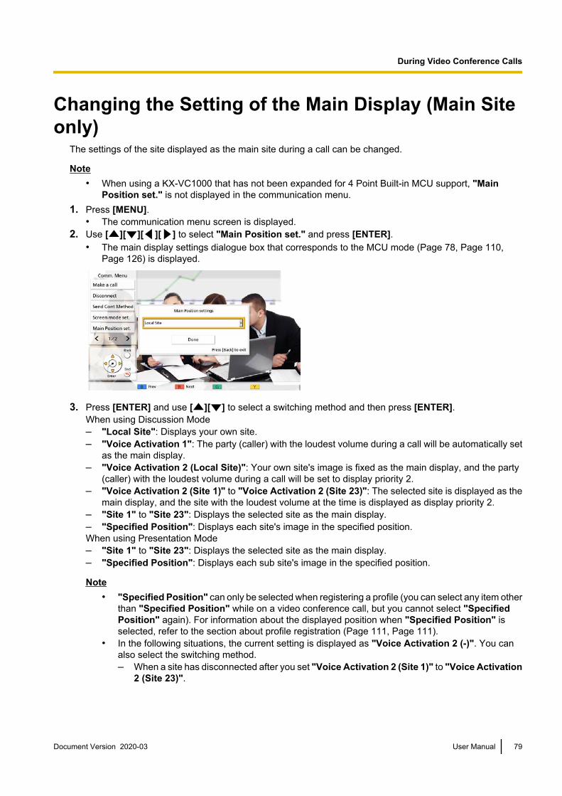
Changing the Setting of the Main Display (Main Siteonly)
The settings of the site displayed as the main site during a call can be changed.
Note• When using a KX-VC1000 that has not been expanded for 4 Point Built-in MCU support, "Main
Position set." is not displayed in the communication menu.1. Press [MENU].
• The communication menu screen is displayed.2. Use [ ][ ][ ][ ] to select "Main Position set." and press [ENTER].
• The main display settings dialogue box that corresponds to the MCU mode (Page 78, Page 110,Page 126) is displayed.
3. Press [ENTER] and use [ ][ ] to select a switching method and then press [ENTER].When using Discussion Mode– "Local Site": Displays your own site.– "Voice Activation 1": The party (caller) with the loudest volume during a call will be automatically set
as the main display.– "Voice Activation 2 (Local Site)": Your own site's image is fixed as the main display, and the party
(caller) with the loudest volume during a call will be set to display priority 2.– "Voice Activation 2 (Site 1)" to "Voice Activation 2 (Site 23)": The selected site is displayed as the
main display, and the site with the loudest volume at the time is displayed as display priority 2.– "Site 1" to "Site 23": Displays the selected site as the main display.– "Specified Position": Displays each site's image in the specified position.When using Presentation Mode– "Site 1" to "Site 23": Displays the selected site as the main display.– "Specified Position": Displays each sub site's image in the specified position.
Note• "Specified Position" can only be selected when registering a profile (you can select any item other
than "Specified Position" while on a video conference call, but you cannot select "SpecifiedPosition" again). For information about the displayed position when "Specified Position" isselected, refer to the section about profile registration (Page 111, Page 111).
• In the following situations, the current setting is displayed as "Voice Activation 2 (-)". You canalso select the switching method.– When a site has disconnected after you set "Voice Activation 2 (Site 1)" to "Voice Activation
2 (Site 23)".
Document Version 2020-03 User Manual 79
During Video Conference Calls
– When "Main Position (Discussion)" is set to "Voice Activation 2 (Site 1)" to "VoiceActivation 2 (Site 30)" in the site's registration, and the selected site is not connected(Page 111).
4. Use [ ][ ] to select "Done" and press [ENTER].
Note• When sharing content via single stream communication, the content will automatically displayed
as the main display.
80 User Manual Document Version 2020-03
During Video Conference Calls

Changing the Site Name Display (Main Site only)The setting of whether site names are displayed during a video conference call can be changed.
Note• When using a KX-VC1000 that has not been expanded for 4 Point Built-in MCU support, "Site name
display" is not displayed in the communication menu.1. Press [MENU].
• The communication menu screen is displayed.2. Use [ ][ ][ ][ ] to select "Site name display" and press [ENTER].
• The site name display setting dialogue box is displayed.
3. Use [ ][ ] to select whether to display a site name ("ON", "OFF"), and press [ENTER].
Document Version 2020-03 User Manual 81
During Video Conference Calls

Changing the Audio Settings for Other Parties (MainSite only)
During a video conference call, you can change the mode that is used to mix the audio from your own site andthe other party's site.
Note• When using a KX-VC1000 that has not been expanded for 4 Point Built-in MCU support, "Other
Site's Audio" is not displayed in the communication menu.1. Press [MENU].
• The communication menu screen is displayed.2. Use [ ][ ][ ][ ] to select "Other Site's Audio" and press [ENTER].
• The other party’s audio setting dialogue box is displayed.
3. Use [ ][ ] to select "Mix (Auto)", "Mix (Selection)", or "Mute" and press [ENTER].– "Mix (Auto)" (default): Audio from the loudest 4 sites is automatically mixed together.– "Mix (Selection)": The audio from the selected sites (up to 4) is mixed together.– "Mute": Mutes the audio of the other party. Only the audio of the Main Site is output.
82 User Manual Document Version 2020-03
During Video Conference Calls

Changing the Settings for Audio Mixing Sites (MainSite Only)
When "Other Site's Audio" is set to "Mix (Selection)", you can change the audio settings for sites whoseaudio is mixed together. (Page 82, Page 110)
Note• When using a KX-VC1000 that has not been expanded for 4 Point Built-in MCU support, "Audio Mixing
Site" is not displayed in the communication menu.1. Press [MENU].
• The communication menu screen is displayed.2. Use [ ][ ][ ][ ] to select "Audio Mixing Site" and press [ENTER].
• Audio mixing site setting dialogue box is displayed.
3. Use [ ][ ] to select the sites whose audio will be mixed together and press [ENTER].• Press [ENTER] to select/deselect the desired sites. You can select up to 4 sites.
4. Use [ ][ ] to select "Done" and press [ENTER].
Note• This setting is only available when "Other Site's Audio" in the communication menu (Page 82) or
"Other Site's Audio" in the profile setup (Page 110) is set to "Mix (Selection)".
Starting and Stopping RecordingYou can start and stop recording during a video conference call. The recorded video and audio are saved onthe USB memory device connected to the back of the unit.
Note• For details about recording features, refer to "Using USB Recording Features (Page 187)".• You can also start and stop recording while idle (Page 134).
1. Press [MENU].• The communication menu screen is displayed.
2. Use [ ][ ][ ][ ] to select "USB Rec" and press [ENTER].• The dialogue box to start or stop recording is displayed.
3. Use [ ][ ] to select "Yes" or "No" and press [ENTER].When not recording– Selecting "Yes" starts recording.– Selecting "No" does not start recording.
Document Version 2020-03 User Manual 83
During Video Conference Calls

When recording– Selecting "Yes" stops recording.– Selecting "No" does not stop recording.
NoteIf you set "USB Rec" to ""G" Button during call" in "GUI Settings", you can start and stop recordingduring a call using [G] (Page 156).
Displaying how the PC is connectedDisplays how the PC is connected when using Web Hybrid Mode.1. Press [MENU].
• The communication menu screen is displayed.2. Use [ ][ ][ ][ ] to select "How to connect PC" and press [ENTER].
• Displays the connection method of the HD Visual Communication Unit and computer when using WebHybrid Mode.
3. Press [ENTER].• The display returns to the communication menu screen.
Note• "How to connect PC" is displayed when "Web Hybrid Mode" is set to "ON (Permanent)" or "ON
(Temporary)" (Page 136).
84 User Manual Document Version 2020-03
During Video Conference Calls

Checking the Call HistoryThe history of the connections with other sites from the start of the call to the present can be checked.1. Press [B] during a video conference call.
• The call history screen is displayed.
2. Press [BACK].• The display returns to the video conference call screen.
Note• You can use [ ][ ] to scroll in the call history screen and display the previous or next history entry.• If no operations are performed for approximately 10 seconds after the call history screen is displayed,
the display returns to the video conference call screen.• The call history of sites that the other party in the video conference call has connected to are not
displayed.
Document Version 2020-03 User Manual 85
During Video Conference Calls

Adjusting the VolumeYou can adjust the volume during a video conference call.
1 Press [VOLUME (+/–)].• The volume level bar is displayed at the bottom of
the screen.
1, 2
2 Adjust the volume using [VOLUME (+/–)].• Pressing [+] will increase the volume of the other
party’s voice.• Pressing [–] will decrease the volume of the other
party’s voice.
After about 3 seconds, the volume level bar disappears.
Note• You can set the volume level of a video conference call before starting the call (Page 130).• After ending a video conference call, the volume level returns to the volume level set before starting
the call.• You cannot adjust the display’s volume.
86 User Manual Document Version 2020-03
During Video Conference Calls

Muting the MicrophoneDuring a video conference call, you can mute the microphone so that your voice cannot be heard by the otherparty. You will be able to hear the other party’s voice, but they will not be able to hear you.
Note• You can set the microphone(s) to be mute at the start of a video conference call regardless of which
party initiated the call (Page 125).
Muting the Microphone (Operation with the Remote Control)1 Press [MIC MUTE].
• An icon appears in the status display area of thescreen (Page 41), and the LED light on the BoundaryMicrophone becomes red. Make sure the colour ofthe LED changes.
• Pressing [MIC MUTE] again will unmute themicrophone. The LED light on the BoundaryMicrophone becomes green. Make sure the colourof the LED changes.
1
Document Version 2020-03 User Manual 87
During Video Conference Calls

Muting the Microphone (Operation with the Boundary Microphone)1 Press the MIC Mute button.
• An icon appears in the status display area ofthe screen (Page 41), and the LED light on theBoundary Microphone becomes red. Makesure the colour of the LED changes.
• Pressing the MIC Mute button again willunmute the microphone. The LED light on theBoundary Microphone becomes green. Makesure the colour of the LED changes.
Note• When multiple Digital Boundary
Microphones are connected, pressingthe MIC Mute button of one DigitalBoundary Microphone will mute allDigital Boundary Microphones.
• When using Digital BoundaryMicrophones and an AnalogueBoundary Microphone together,pressing the MIC Mute button on oneBoundary Microphone will mute allBoundary Microphones.
• If a headset is connected, the MIC Mutebutton on a Boundary Microphone willnot work.
1 1
Digital BoundaryMicrophone
Analogue BoundaryMicrophone
88 User Manual Document Version 2020-03
During Video Conference Calls

Reducing Microphone NoiseYou can reduce the amount of ambient noise picked up by the microphone (shuffling of papers, etc.) during avideo conference call. When noise reduction is in effect, the volume level of voices may also be reduced.
1 Press [Y].• "Whisper Mode [ON]" is displayed, and noise
reduction is enabled.
• Pressing [Y] again will display "Whisper Mode[OFF]", and noise reduction is disabled.
Note• Noise reduction is available only when Digital
Boundary Microphones are connected.• You can set whether to enable noise reduction
for a video conference call before starting thecall (Page 125).
• After a video conference call is finished, thenoise reduction setting returns to the value setbefore starting the call.
• When ""Y" Button during MCU" in "GUISettings" is set to "Discussion /Presentation", you can switch the MCU modeby pressing the [Y] button during calls that usethe MCU (except for KX-VC1000) (Page 156).
• This feature is disabled for KX-VC1000, andnoise reduction is not displayed on the [Y] buttonin the shortcut key area. If the unit has beenexpanded for 4 Point Built-in MCU support, theoption to change the MCU mode is assigned tothe [Y] button during video conferences that usethe MCU.
1
Document Version 2020-03 User Manual 89
During Video Conference Calls

Displaying a Computer’s Screen and the Sub VideoCamera’s Image
When a computer or sub video camera is connected to the unit, you can display the computer’s screen or thesub video camera’s image on your display and to other parties. This is convenient when explaining somethingon the computer’s screen or the sub video camera’s image while showing them to others, for example.
Main video
cameraMain video
cameraSub video
camera
Sub video
camera
Computer Computer
Router RouterInternet
Note• The computer screen resolutions supported by the unit are VGA (640 ´ 480), SVGA (800 ´ 600), XGA
(1024 ´ 768), HD (1280 ´ 720), and WXGA (1280 ´ 768, 1280 ´ 800), SXGA (1280 ´ 1024), FWXGA(1360 768, 1366 768), WXGA+ (1440 900), WXGA++ (1600 900), UXGA (1600 1200), WSXGA+ (1680 ´ 1050), Full-HD (1920 ´ 1080).
1. Press [PC] or [CAMERA SUB] during a video conference call.For dual stream communication:• You can send the image of your video camera and the image of your computer’s screen or a sub video
camera at the same time to the other party. You can view the other party and check shared data at thesame time.
Note• If dual stream communication is disabled in the communication settings (Page 124), or if a device
that does not support dual stream communication is connected, the screen switching method willbe used.
When using the screen switching method (hereafter referred to as "single stream communication"):• Switches the display from the image of the main video camera to that of the computer’s screen or the
image of the sub camera. The same image is also shown on the other party’s display.2. Press [CAMERA MAIN] to return to the image of the main video camera.
90 User Manual Document Version 2020-03
During Video Conference Calls

Example: single stream communication (2 screensused, 4-party video conference, at the Main Site)
Example: dual stream communication (2 screensused, 4-party video conference, at the Main Site)
Without contentssharing
Without contentssharing
Site 1 Site 2 Your Own Site
HDMI1 HDMI2
Site 3 Site 4
[CAMERA MAIN] [PC]/[CAMERA SUB]
Site 1 Site 2
HDMI1 HDMI2
Site 3 Site 4
[CAMERA MAIN] [PC]/[CAMERA SUB]
Your Own Site
With contentssharing
With contentssharing
Other Video Sources
Other Video Sources
Other Video Sources
Other Video Sources
[LAYOUT]
[LAYOUT]
[LAYOUT]
Other Video Sources
Other Video Sources
Other Video Sources
Other Video Sources
Other Video Sources
Other Video Sources
Site 2Site 1
Site 3 Site 4
Site 2Site 1
[LAYOUT]
[LAYOUT]
[LAYOUT]
Site 3 Site 4
*Sites 1 through 4 are your own site or another party’s site.
Document Version 2020-03 User Manual 91
During Video Conference Calls

Note• Pressing [LAYOUT] in succession will
switch the displays of the 2 monitors indifferent combinations of the contents imagedisplay, the contents image combined withthe camera image, and the camera imagedisplay.
• For single stream communication:– During a 2-party call, depending on the
screen layout state of the other party, thedisplay of the other party may not showthe same screen as yours. In suchcases, press [CAMERA MAIN] to cancelcontents sharing, or instruct the otherparty to change their screen layout toone that displays your screen.
• For dual stream communication:– While sharing the contents of a
computer’s screen or the sub cameraimage, the other party can also sharetheir contents. Note that in this case, theimages for the contents of all sites willchange to the last shared image.
• While the Home screen (idle screen) isdisplayed, pressing [PC] or [CAMERASUB] will display the contents of thecomputer’s screen or the sub camera’simage. When displaying the computer’sscreen or the image of the sub camera, thesystem will not enter screen standby mode.To return to the Home screen, press[CAMERA MAIN].
92 User Manual Document Version 2020-03
During Video Conference Calls

Controlling a Video CameraIf a PTZ (pan, tilt, zoom) camera or a FIX camera is connected to your unit or the other party’s unit, you cancontrol the pan (side-to-side movement), the tilt (up-down movement), and the zoom of the video camera duringa video conference call. You can perform this operation with the main video camera or a sub video camera.
Note• In this manual, "PTZ camera" indicates a video camera whose moving parts will rotate when the
direction of the video camera is changed. "FIX camera" indicates a video camera that has no movingparts and does not rotate.
• For details about compatible video camera models, contact your dealer.• The features that can be used may be limited depending on your video camera model.
(e.g., A video camera with only a zoom feature)• When the other party is using a non-Panasonic video conference system, some operations may not
be available, or unintended operations may occur.• The setting "Direct Cam Ctrl on Home Screen" can be used to disable the operation of idle video
cameras (Page 133).• If any of the other parties is using the KX-VC500, KX-VC300 or KX-VC600 with a software version
older than 2.30 (not including 2.30), you will not be able to control any of the other party’s videocameras. You will only be able to control your own video camera.
• In order for other parties to be able to control your video camera, you must set "CAM ctrl from remotesite(s)" in your settings to "ON" (by default, it is set to "OFF") (Page 133).
• The Main Site can operate the cameras of all sites, and Sub Sites can operate their own camera andthe camera of the site being displayed as the main display at the Main Site.
• For video conference calls with multiple connections that use an internal MCU, in order for a sub siteto control a camera of another site, the main site's "Camera control transmitting" setting (default:"OFF") must be set to "ON" (Page 128), and the "CAM ctrl from remote site(s)" setting (default"OFF") must be set to "ON" (Page 133).
Operating your own video camera directlyYou can directly perform PTZ (pan/tilt/zoom) operations fromthe home screen and the video conference call screen usingthe remote control.
3
1, 2
1. [ ][ ]: Tilt the video camera up/down.
2. [ ][ ]: Pan the video camera left/right.
3. [ZOOM (+/-)]: Zoom in/zoom out the videocamera.
Document Version 2020-03 User Manual 93
C
o
n
t
r
o
l
l
i
n
g
a
V
i
d
e
o
C
a
m
e
r
a
Controlling a Video Camera

Note• Your own video camera’s image will be displayed when operations are performed during a call so that
you can confirm the operations. If no operation is made for approximately 3 seconds, the original screenis displayed.
Operation from the video camera menu1 Press [CAM CTRL].
• The site selection dialogue box is displayed.
Note• After the site selection dialogue box is displayed,
if no operations are performed withinapproximately 10 seconds, the dialogue box willdisappear.
31
2, 3
2 Use [ ][ ] to select the site to display and press[ENTER].• The camera control screen is displayed.
94 User Manual Document Version 2020-03
Controlling a Video Camera

3 Press the buttons on the remote control to operate thevideo camera.[ZOOM (+/-)]: Zoom in/zoom out[ ][ ]: Pan the video camera left/right.[ ][ ]: Tilt the video camera up/down.
• The movement continues as long as you hold downthe button, and stops when you release the button.For finer control of the movement, press the buttonand immediately release it, and repeat this insuccession.
• To return to the video conference call screen, press[BACK].
Note• You can press [FULL SCREEN] on the remote control to display/hide the guide area. You can specify
in the administrator menu (Page 155) whether the entire guide area is hidden, or only a portion of it.• In the following cases, you will not be able to control a video camera, even if you press [CAM CTRL].
– While displaying the unit information screen or the connections status screen.– While displaying a dialogue box.
Document Version 2020-03 User Manual 95
Controlling a Video Camera

Registering a PresetWhen you are not on a video conference call, you can register up to 12 presets (pan, tilt, zoom position, etc.)of the video camera connected as the main or sub video camera on your side.
Note• Preset registration can only be performed when using video cameras that support preset functions.
For details, contact your dealer.• The features that can be used may be limited depending on your video camera model.
(e.g., A video camera with only a zoom feature)
1 Press [HOME].• The Home screen is displayed.
Note• If you are registering presets for the sub video
camera, press [CAMERA SUB].
5
3, 6
5, 7
2
1, 8
4
2 Press [CAM CTRL].• The camera control screen for your own video
camera is displayed.
3 Press [G].• The preset screen is displayed.
96 User Manual Document Version 2020-03
Controlling a Video Camera

4 Press a numeric button (0–9, *, #) to select the presetnumber to use.• The selected preset number is displayed in the
upper right corner of the screen.
Note• The following preset numbers are assigned to
the numeric buttons on the remote control.
* KX-VD170 is tested with the preset numbers that
are assumed to be used with KX-VD170.
Numeric button
1
2
3
4
5
6
7
8
9
0
*#
1
2
3
4
5
6
7
8
9
10*
11*
12*
Preset number
• When a preset number that has already beenregistered is selected and preset registration isperformed, that preset’s registered informationwill be overwritten.
5 Press the buttons on the remote control to adjust thevideo camera’s preset.[ZOOM (+/-)]: Zoom in/zoom out[ ][ ]: Pan the video camera left/right.[ ][ ]: Tilt the video camera up/down.
6 Press [G].• A dialogue box to confirm the saving of settings is
displayed.
Document Version 2020-03 User Manual 97
Controlling a Video Camera
7 Use [ ][ ] to select "Yes" and press [ENTER].• The preset screen is displayed.
Note• To continue making settings, repeat steps 4–7.
8 Press [HOME].• The Home screen is displayed.
Note• Preset registration information for a video
camera is saved in that video camera. If a videocamera is initialised, its preset registrationinformation will be lost. In such cases, presetregistration must be performed on the unit again.
98 User Manual Document Version 2020-03
Controlling a Video Camera

Recalling a Registered PresetDuring a video conference call, you can set your own video camera’s direction, zoom and magnifier settings,etc., to the desired state by selecting a registered preset.
Note• For details about compatible video camera models, contact your dealer.• You can recall a preset that was set by the other party for the other party’s video camera during a video
conference call.
1 Press [CAM CTRL].• The site selection dialogue box is displayed.
Note• After the site selection dialogue box is displayed,
if no operations are performed withinapproximately 10 seconds, the dialogue box willdisappear.
2
1
3
2 Use [ ][ ] to select "Local Site" and press[ENTER].• The camera control screen is displayed.
Document Version 2020-03 User Manual 99
Controlling a Video Camera

3 Press a numeric button (0–9, *, #) to select the presetnumber that you want to recall.• The direction and zoom of your video camera will
change to that of the registered preset.
Note• The following preset numbers are assigned to
the numeric buttons on the remote control.
* KX-VD170 is tested with the preset numbers that
are assumed to be used with KX-VD170.
Numeric button
1
2
3
4
5
6
7
8
9
0
*#
1
2
3
4
5
6
7
8
9
10*
11*
12*
Preset number
100 User Manual Document Version 2020-03
Controlling a Video Camera
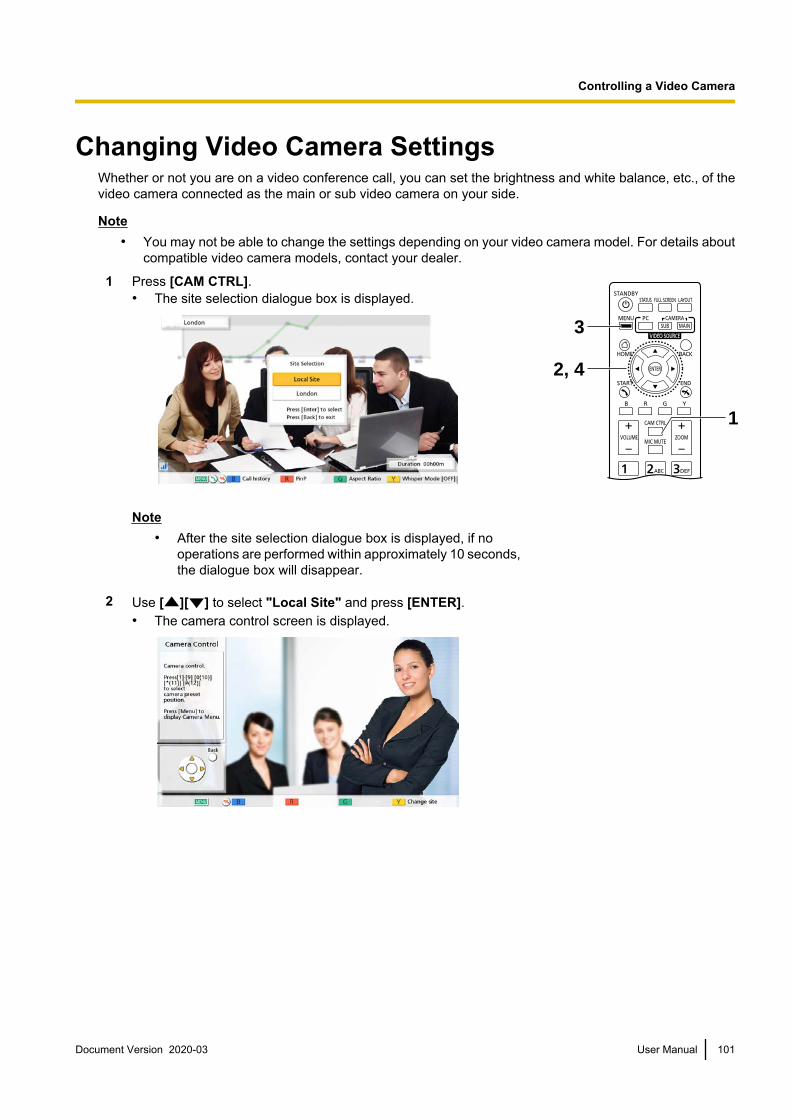
Changing Video Camera SettingsWhether or not you are on a video conference call, you can set the brightness and white balance, etc., of thevideo camera connected as the main or sub video camera on your side.
Note• You may not be able to change the settings depending on your video camera model. For details about
compatible video camera models, contact your dealer.
1 Press [CAM CTRL].• The site selection dialogue box is displayed.
Note• After the site selection dialogue box is displayed, if no
operations are performed within approximately 10 seconds,the dialogue box will disappear.
1
2, 4
3
2 Use [ ][ ] to select "Local Site" and press [ENTER].• The camera control screen is displayed.
Document Version 2020-03 User Manual 101
Controlling a Video Camera
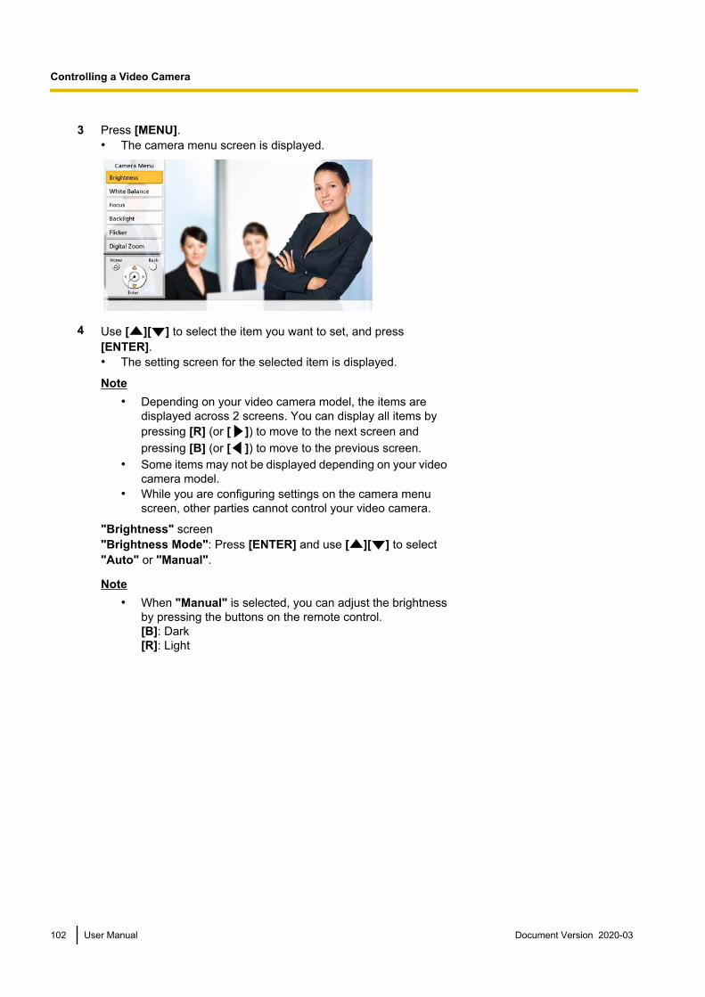
3 Press [MENU].• The camera menu screen is displayed.
4 Use [ ][ ] to select the item you want to set, and press[ENTER].• The setting screen for the selected item is displayed.
Note• Depending on your video camera model, the items are
displayed across 2 screens. You can display all items bypressing [R] (or [ ]) to move to the next screen andpressing [B] (or [ ]) to move to the previous screen.
• Some items may not be displayed depending on your videocamera model.
• While you are configuring settings on the camera menuscreen, other parties cannot control your video camera.
"Brightness" screen"Brightness Mode": Press [ENTER] and use [ ][ ] to select"Auto" or "Manual".
Note• When "Manual" is selected, you can adjust the brightness
by pressing the buttons on the remote control.[B]: Dark[R]: Light
102 User Manual Document Version 2020-03
Controlling a Video Camera

"White Balance" screenThis function adjusts the colour so that white colours always appearwhite under various types of light sources.
"White Balance": Press [ENTER] and use [ ][ ] to select thedesired value for the white balance ("Auto", "Indoor 1", "Indoor2", "Outdoor (Sunny)", "Outdoor (Cloudy)", or "Calibrate").
Note• Unless the colour is unnatural due to the light source, for
instance, select "Auto".• "Indoor 1" is recommended if the light source is an
incandescent lamp, etc. "Indoor 2" is recommended if thelight source is a warm, white fluorescent lamp, sodiumvapour lamp, etc.
• When "Calibrate" is selected, you can adjust the whitebalance. Perform the following procedure:
1. Press [ENTER].• If the white balance had been set before by
selecting "Calibrate", that previously set state willbe recalled.
2. Turn a piece of white paper toward the video camera.3. Press [G].
"Focus" screen: Use [ ][ ] to select the following items for input:
"Focus Position": Press [ENTER] and use [ ][ ] to select"Center" or "Sides (Wide)"."Focus Mode": Press [ENTER] and use [ ][ ] to select"Auto" or "Manual".
Note• When "Manual" is selected, you can adjust the focus by
pressing the buttons on the remote control.[B]: Near[R]: Far
"Backlight" screenThis function adjusts the colour so that backlit objects do not appeardark.
"Backlight Compensation": Press [ENTER] and use [ ][ ] toselect "ON" or "OFF".
"Flicker" screenThis function corrects screen flicker.
"Flicker Compensation": Press [ENTER] and use [ ][ ] toselect "ON" or "OFF".
Document Version 2020-03 User Manual 103
Controlling a Video Camera

"Digital Zoom" screenThis function crops the centre part of the video image and enlargesit through digital processing.
"Digital Zoom": Press [ENTER] and use [ ][ ] to select "ON"or "OFF".
"Sharpness" screenThis function adjusts the sharpness of the contours of images."Sharpness": Press [ENTER] and use [ ][ ] to select "High", "Medium", "Low", or "Off".
"Noise Filter" screenThis function filters the image noise when there is low illumination, etc. If a high setting is used, residualimages may be increased."Noise Filter": Press [ENTER] and use [ ][ ] to select "High", "Medium", "Low", or "Off".
Note• After completing settings on each settings screen, press [ENTER]. After that, pressing
[MENU] or [BACK] will display the camera menu screen.
104 User Manual Document Version 2020-03
Controlling a Video Camera

Displaying the Connection StatusYou can confirm the connection status of the network and peripheral devices.
1 Press [STATUS].• The connections status screen is displayed. A "–"
mark is displayed next to any network or peripheraldevices connection that is not in normal operation ornot connected. 2
1
2 Press [BACK].• The display returns to the screen in use before the
connections status screen was viewed.
Note• During a call, press [STATUS] twice at step 1.• "Digital" is not displayed for "MIC Input" for the
KX-VC1000.• If the KX-VC1000 has not been expanded for
HDMI Dual Monitor support, "HDMI 2" is notdisplayed for "Video Output".
• "HDMI 3" for "Video Output" and "LAN 2" for"Network" are only displayed for theKX-VC1600 and KX-VC2000.
Document Version 2020-03 User Manual 105
D
i
s
p
l
a
y
i
n
g
t
h
e
C
o
n
n
e
c
t
i
o
n
S
t
a
t
u
s
Displaying the Connection Status

Displaying Unit InformationNote
• Describes the information displayed for devices other than those that are currently being used in amulticast. For the display of information for devices that are currently being used in a multicast, referto "Confirming the Transmission Status During a Multicast (Multicast Terminal) (Page 185)" and"Confirming the Transmission Status During a Multicast (Relay Terminal/Receiver Terminal)(Page 186)".
1 Press [STATUS] twice.• The unit information screen is displayed.
• The unit information display screen is displayed over 2 to 3 screens.To view all the items, press [R] to move to the next page, and press[B] to move to the previous page.
1
Note• The status of communication encryption (ON/OFF/Best effort)
is displayed under "Encryption (SIP)"/"Encryption (H.323)"/"Encryption (NAT Traversal)".
• When not in a video conference call, the first and second pagesdisplay information for your own site.
• When in a video conference call, the first page displaysinformation for the other party’s site and second and third pagesdisplay information for your own site. The first page of informationcan be used to confirm the network’s status during a call,including the connection bandwidth and the packet loss ratio.
• During a multiple-party video conference call, pressing [G] on thefirst page will display the site selection dialogue box, where thedisplayed site can be changed. [ ][ ] can also be used insteadof [G] to change the displayed site. When using a KX-VC1000that has not been expanded for 4 Point Built-in MCU support,[G], [ ] and [ ] are unavailable.
• The site that has a black line displayed on the left in the siteselection dialogue box is the site with the lowest bandwidth (ifthere are two types of communication groups due to "SecondaryBandwidth Selection" (Page 129), a black line is displayed inthe site with the lowest bandwidth for each group).
106 User Manual Document Version 2020-03
Displaying the Connection Status

Adding Contacts to theContact ListYou can register the information of up to 600 contactsin the contact list.
Note• If a video conference call is received while data
is being entered, a dialogue box to confirm if youanswer a video conference call is displayed.Use [ ][ ] to select "Yes" or "No" and press[ENTER].– When "Yes" is selected, you can answer a
video conference call while any unsaveddata is lost.
– When "No" is selected, you can continueentering the data.
• You can use the administrator menu to prohibitadding, editing, and deleting items in thecontacts list (Page 156).
Registering a New Contact1. Press [MENU].
• The Menu screen is displayed.
2. Use [ ][ ] to select "Contact List" and press[ENTER].
3. Press [B].• The contact list registration screen is displayed.
4. Use [ ][ ] to select the following items for input:"Site": Enter a name for the contact (up to 24characters) (Page 196)."Sort ID": Enter the Sort ID (maximum 24characters) (Page 196).
Note• If "Sort ID" is saved when it is empty, the
contents of "Site" will be copied to "SortID". If "Site" is saved when it is empty, thecontents of "Sort ID" will be copied to"Site".
"Speed Dial": Enter a speed dial number (1–600)."Max. Bandwidth": Press [ENTER] and use [ ][ ] to select the maximum allowed bandwidth tobe used ("256 kbps"–"18 Mbps", or "NotSpecified" [default]).
Note• When "Not Specified" is selected, the
maximum bandwidth that is set on theconnection settings screen (Page 124) isapplied.
• The maximum bandwidth during a videoconference call adjusts to that of the partythat has set the lowest bandwidth for themaximum bandwidth setting among allparticipating parties.
• Video conferences cannot use morebandwidth than the maximum bandwidthsetting set by your dealer. For details,contact your dealer.
"Connection mode": Press [ENTER] and use[ ][ ] to select the connection mode (call type)("IP Mode (SIP)", "IP Mode (H.323)", or "NATTraversal Mode")."Address": Enter an IP address (or host name),SIP URI (or SIP user name), H.323 extension, H.323 name, MCU’s conference room number@IPaddress, or connection number.
Note• When entering an IPv4 address, if the IP
address contains 1 or 2 digit numbers, enterthese numbers as they are. Do not enter like[.001].Example: The IP address is [192.168.0.1].– Correct entry: [192.168.0.1]– Wrong entry: [192.168.000.001]
• For the IPv6 address input format, refer toPage 47.
Document Version 2020-03 User Manual 107
Contacts and Settings
Contacts and Settings

• When entering an IPv6 address with a portnumber appended, enclose the IPv6address in square brackets.(Input example) [2001:db8::10]:5060
• See Page 47 for details about thecharacters that can be input for addressentry.
• If the other party has the same SIP domainname as yours, you can register only theirSIP user name. If the other party has adifferent SIP domain name from yours, theirSIP domain name must be entered alongwith their SIP user name.
• If the SIP domain name is not entered, yourown SIP domain name is automaticallyappended to the registered contact. Thismay result in a different, unintended partybeing registered as a contact, so be carefulwhen entering a contact’s information.
• When using H.323, you can also enter thefollowing.– IP address (or host name) %H.323
extension (or H.323 name)– IP address (or host name) ##H.323
extension (or H.323 name)• Enter a standards-compliant value.
For details, contact your networkadministrator.
5. Press [G].• A dialogue box to confirm the saving of settings
is displayed.
6. Use [ ][ ] to select "Yes" and press [ENTER].• The contact list screen is displayed.
Note• To continue entering another contact, press
[B] and repeat steps 4–6.
7. Press [HOME].• The Home screen is displayed.
Editing Contact Information1. Press [MENU].
• The Menu screen is displayed.
2. Use [ ][ ] to select "Contact List" and press[ENTER].• The contact list screen is displayed.
3. Use [ ][ ] to select the contact you want to edit.• You can use [ ][ ] or the numeric buttons of
the remote control to select the displayed tab(Page 53).
4. Press [ENTER].• The contact list details screen is displayed.
5. Press [G].• The contact list edit screen is displayed.
6. Use [ ][ ] to select the item you want to edit andmake any changes.
7. Press [G].• A dialogue box to confirm the saving of settings
is displayed.
8. Use [ ][ ] to select "Yes" and press [ENTER].• The contact list details screen is displayed.
9. Press [HOME].• The Home screen is displayed.
Deleting a Contact1. Press [MENU].
• The Menu screen is displayed.
108 User Manual Document Version 2020-03
Contacts and Settings

2. Use [ ][ ] to select "Contact List" and press[ENTER].• The contact list screen is displayed.
3. Use [ ][ ] to select the contact you want todelete.• You can use [ ][ ] or the numeric buttons of
the remote control to select the displayed tab(Page 53).
4. Press [R].• A dialogue box to confirm the deletion is
displayed.
5. Use [ ][ ] to select "Yes" and press [ENTER].• The contact list screen is displayed.
6. Press [HOME].• The Home screen is displayed.
Registering a Contact from theCall HistoryYou can register a contact to the contact list from thecall history.1. Press [MENU].
• The Menu screen is displayed.
2. Use [ ][ ] to select "Call History" and press[ENTER].• The outgoing call history screen is displayed.
Note• To refer to the incoming call history,
press [G].
3. Use [ ][ ] to select the single-party entry youwant to add as a contact, and press [B].• The contact list registration screen is displayed.
4. Use [ ][ ] to select the necessary items andinput information.
5. Press [G].• A dialogue box to confirm the saving of settings
is displayed.
6. Use [ ][ ] to select "Yes" and press [ENTER].• The outgoing or incoming call history screen is
displayed, depending on which of the screensyou displayed in step 2.
7. Press [HOME].• The Home screen is displayed.
Document Version 2020-03 User Manual 109
Contacts and Settings
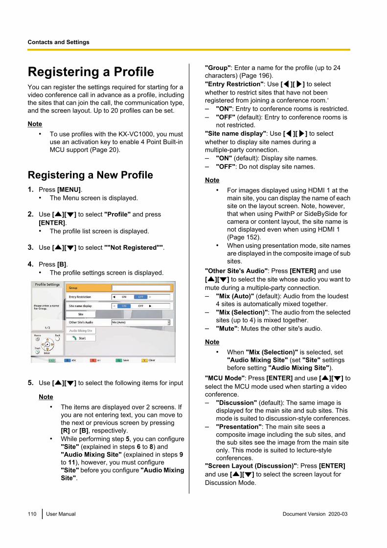
Registering a ProfileYou can register the settings required for starting for avideo conference call in advance as a profile, includingthe sites that can join the call, the communication type,and the screen layout. Up to 20 profiles can be set.
Note• To use profiles with the KX-VC1000, you must
use an activation key to enable 4 Point Built-inMCU support (Page 20).
Registering a New Profile1. Press [MENU].
• The Menu screen is displayed.
2. Use [ ][ ] to select "Profile" and press[ENTER].• The profile list screen is displayed.
3. Use [ ][ ] to select ""Not Registered"".
4. Press [B].• The profile settings screen is displayed.
5. Use [ ][ ] to select the following items for input
Note• The items are displayed over 2 screens. If
you are not entering text, you can move tothe next or previous screen by pressing[R] or [B], respectively.
• While performing step 5, you can configure"Site" (explained in steps 6 to 8) and"Audio Mixing Site" (explained in steps 9to 11), however, you must configure"Site" before you configure "Audio MixingSite".
"Group": Enter a name for the profile (up to 24characters) (Page 196)."Entry Restriction": Use [ ][ ] to selectwhether to restrict sites that have not beenregistered from joining a conference room.‘– "ON": Entry to conference rooms is restricted.– "OFF" (default): Entry to conference rooms is
not restricted."Site name display": Use [ ][ ] to selectwhether to display site names during amultiple-party connection.– "ON" (default): Display site names.– "OFF": Do not display site names.
Note• For images displayed using HDMI 1 at the
main site, you can display the name of eachsite on the layout screen. Note, however,that when using PwithP or SideBySide forcamera or content layout, the site name isnot displayed even when using HDMI 1(Page 152).
• When using presentation mode, site namesare displayed in the composite image of subsites.
"Other Site's Audio": Press [ENTER] and use[ ][ ] to select the site whose audio you want tomute during a multiple-party connection.– "Mix (Auto)" (default): Audio from the loudest
4 sites is automatically mixed together.– "Mix (Selection)": The audio from the selected
sites (up to 4) is mixed together.– "Mute": Mutes the other site's audio.
Note• When "Mix (Selection)" is selected, set
"Audio Mixing Site" (set "Site" settingsbefore setting "Audio Mixing Site").
"MCU Mode": Press [ENTER] and use [ ][ ] toselect the MCU mode used when starting a videoconference.– "Discussion" (default): The same image is
displayed for the main site and sub sites. Thismode is suited to discussion-style conferences.
– "Presentation": The main site sees acomposite image including the sub sites, andthe sub sites see the image from the main siteonly. This mode is suited to lecture-styleconferences.
"Screen Layout (Discussion)": Press [ENTER]and use [ ][ ] to select the screen layout forDiscussion Mode.
110 User Manual Document Version 2020-03
Contacts and Settings

– "Auto" (default): Automatically changes thelayout depending on the number of sites joininga video conference call.
– "CP1" to "CP28": The selected screen layoutis used (Page 74).
"Screen Layout (Presentation)": Press [ENTER]and use [ ][ ] to select the screen layout forPresentation Mode.– "Auto" (default): Automatically changes the
layout depending on the number of sites joininga video conference call.
– "CP1" to "CP28": The selected screen layoutis used (Page 74).
"Main Position (Discussion)": Press [ENTER]and use [ ][ ] to select the screen to display asthe main display (display priority 1).– "Local Site" (default): Displays your own site.– "Voice Activation 1": The site with the loudest
volume is automatically displayed as the maindisplay.
– "Voice Activation 2 (Local Site)": Your ownsite's image is displayed as the main display,and the site with the loudest volume at the timeis displayed as display priority 2.
– "Voice Activation 2 (Site 1)" to "VoiceActivation 2 (Site 30)": The selected site isdisplayed as the main display, and the site withthe loudest volume at the time is displayed asdisplay priority 2.
– "Site 1" to "Site 30": The selected site isdisplayed as the main display.
– "Specified Position": Displays each site'simage in the specified position.
Note• When "Specified Position" is selected, the
main site is displayed at the positionspecified by "Display position of localsite". Sub sites are displayed in the displayposition (except for the main site's displayposition) determined by their priority, whichis determined by the "Site" ID assigned totheir profile settings (lower IDs havepriority).For information about the relationshipbetween display priority order and displaypositions, see (Page 74).
"Main Position (Presentation)": Press [ENTER]and use [ ][ ] to select the screen to display asthe main display (display priority 1).– "Site 1" (default) to "Site 30": The selected site
is displayed as the main display.
– "Specified Position": Displays each sub site'simage in the specified position.
Note• When "Specified Position" is selected,
sites are displayed in the display positiondetermined by their priority, which isdetermined by the "Site" ID assigned totheir profile settings (lower IDs havepriority).For information about the relationshipbetween display priority order and displaypositions, see (Page 74).
"Display position of local site": Press [ENTER]and use [ ][ ] to select the display position ofyour site (display priority position; 1 (default) to 24).
Note• This setting is only available when
"Specified Position" is selected for "MainPosition (Discussion)".
• If the specified display position is greaterthan the number of connected sub sites, thedisplay position automatically movesforward.
• For information about the relationshipbetween display priority order and displaypositions, see (Page 74).
"Display position setting": Press [ENTER] anduse [ ][ ] to select what happens when the siteassigned to the display position is not connected.– "Move forward" (default): Available sites move
forward in their display position.– "Black screen": A black screen is displayed for
any sites that are not connected.
Note• This setting is only available when
"Specified Position" is selected for "MainPosition (Discussion)" or "Main Position(Presentation)".
Document Version 2020-03 User Manual 111
Contacts and Settings

6. Use [ ][ ] to select "Site" and press [ENTER].• The site selection screen is displayed.
Note• If there are no registered contacts with a
" " mark in the selection column, a call willnot be made even if [START] is pressed.
• Press [Y] to return to the profile settingsscreen (first page).
• Up to 30 connections can be registered, butthe number of usable connections will beautomatically selected from the top afterinvalid settings (""Not Registered"" and"Connection mode (Call type)") areexcluded.
7. Use [ ][ ] to select ""Not Registered"" andpress [B].• A dialogue box is displayed for selecting the
input method.
When "Input Address" is selected• The address input screen is displayed.
Use [ ][ ] to select the following itemsfor input:"Connection mode": Press [ENTER] anduse [ ][ ] to select the connection mode(communication type) and press [ENTER].– "IP Mode (SIP)" (default): SIP is used
for communication.
– "IP Mode (H.323)": H.323 is used forcommunication.
– "NAT Traversal Mode": NAT TraversalMode is used for communication.
"Address": Enter an IP address (or hostname), SIP URI (or SIP user name), H.323extension, H.323 name, MCU’s conferenceroom number@IP address, or connectionnumber.Press [G].• The site selection screen is displayed.
When selecting "Contact list":• The contact list screen is displayed.
Use [ ][ ] to select the other party toregister, and press [ENTER].
• The site selection screen is displayed.
When selecting "Call History":• The outgoing call history selection screen is
displayed.Use [ ][ ] to select the other party toregister, and press [ENTER].
• The site selection screen is displayed.
Note• After performing step 7, if you do not set
"Audio Mixing Site" or any of the items instep 5, do not perform steps 8-11 andproceed from step 12.
8. Press [Y].The profile settings screen (first page) is displayed.
9. Use [ ][ ] to select "Audio Mixing Site" andpress [ENTER].• The audio mixing site screen is displayed.
Note• This setting is only necessary when "Other
Site's Audio" is set to "Mix (Selection)".
112 User Manual Document Version 2020-03
Contacts and Settings

10. Use [ ][ ] to select the sites whose audio youwant to mix and press [ENTER].• Press [ENTER] to select/deselect the desired
sites. You can select up to 4 sites.
Note• If no sites are registered, only your own site
can be selected. Perform steps 6-8 first andsetup a site.
11. Press [G]• The profile settings screen is displayed.
12. Press [G].• A dialogue box to confirm the saving of settings
is displayed.
13. Use [ ][ ] to select "Yes" and press [ENTER].• The profile list screen is displayed.
14. Press [HOME].• The Home screen is displayed.
Note• To continue entering another profile, press [B]
from the profile list and repeat steps 3-13.
Editing Profile Information1. Press [MENU].
• The Menu screen is displayed.
2. Use [ ][ ] to select "Profile" and press[ENTER].• The profile list screen is displayed.
3. Use [ ][ ] to select the profile you want to edit.
4. Press [B].• The profile settings screen is displayed.
Note• The items are displayed over 2 screens. If
you are not entering text, you can move tothe next or previous screen by pressing[R] or [B], respectively.
5. Use [ ][ ] to select the item you want to edit andmake any changes.
6. Press [G].• A dialogue box to confirm the saving of settings
is displayed.
7. Use [ ][ ] to select "Yes" and press [ENTER].• The profile list screen is displayed.
8. Press [HOME].• The Home screen is displayed.
Deleting a Profile1. Press [MENU].
• The Menu screen is displayed.
2. Use [ ][ ] to select "Profile" and press[ENTER].• The profile list screen is displayed.
3. Use [ ][ ] to select the profile you want to delete.
4. Press [R].• A dialogue box to confirm the deletion is
displayed.
Document Version 2020-03 User Manual 113
Contacts and Settings

5. Use [ ][ ] to select "Yes" and press [ENTER].• The profile list screen is displayed.
6. Press [HOME].• The Home screen is displayed.
Setting the Profile StandbyWhen an incoming call is received during standby, thespecified conference registered to the profile is started.
Note• Even in the profile standby settings, there are
no restrictions to the call operations (such ashow to make calls and addresses) duringstandby.
• During profile standby settings, if another profilestandby is configured, the first profile standbythat was configured is removed.
• For profiles that have "Entry Restriction" setto "ON", calls are answered and conferencesare started with profile settings only if there is acall from the sites registered in "Site".
• The profile standby setting is set as standby forthe selected local site (page 115) from themoment it is set, and is only enabled while thatlocal site is selected. If the local site is changed,the profile standby is also changed to thecontent of the changed local site while that localsite is selected.
1. Press [MENU].• The Menu screen is displayed.
2. Use [ ][ ] to select "Profile" and press[ENTER].• The profile list screen is displayed.
3. Use [ ][ ] to select the profile standby you wantto use.
Note• The ""Not Registered"" line cannot be
selected.4. Press [G].
• A dialogue box for setting or removing profilestandby is displayed.
5. Use [ ][ ] to select "Temporary" or"Permanent".• The profile list screen is displayed and a "ü" is
displayed in the "Standby" column for theprofile with a standby set.
Note• If "Temporary" is selected, the profile
standby setting is removed if the unit isrestarted (It is also removed if there is anautomatic restart from transferring thecontact list, changing settings, etc.). If"Permanent" is selected, the profilestandby setting is kept even after restartingthe unit.
• If [BACK] is pressed, profile standby is notset and the display is returned to the profilelist screen.
6. Press [HOME].• The Home screen is displayed.
Removing a Profile Standby1. Press [MENU].
• The Menu screen is displayed.
2. Use [ ][ ] to select "Profile" and press[ENTER].• The profile list screen is displayed and a "ü" is
displayed in the "Standby" column for theprofile with a standby set.
3. Use [ ][ ] to select the profile standby you wantto remove.
4. Press [G].• A dialogue box for setting or removing profile
standby is displayed.
5. Use [ ][ ] to select "Release".• The profile list screen is displayed and a "ü" is
deleted from the "Standby" column for theprofile with a standby removed.
Note• If [BACK] is pressed, profile standby is not
removed and the display is returned to theprofile list screen.
6. Press [HOME].• The Home screen is displayed.
114 User Manual Document Version 2020-03
Contacts and Settings
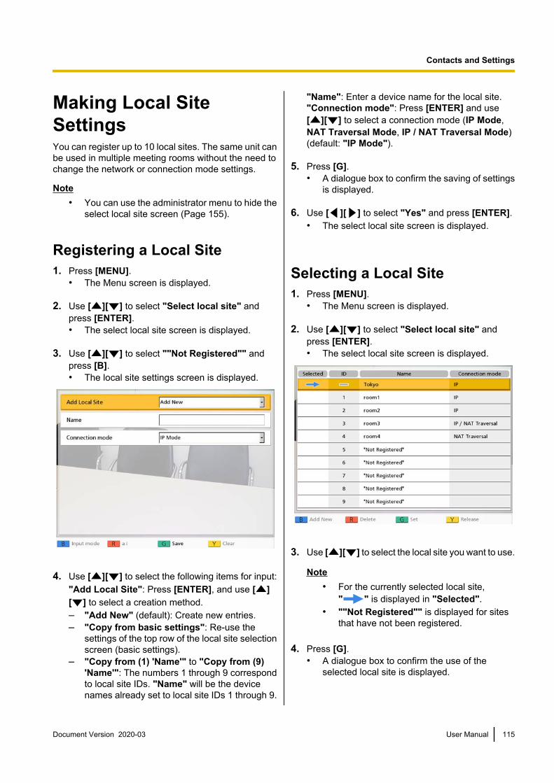
Making Local SiteSettingsYou can register up to 10 local sites. The same unit canbe used in multiple meeting rooms without the need tochange the network or connection mode settings.
Note• You can use the administrator menu to hide the
select local site screen (Page 155).
Registering a Local Site1. Press [MENU].
• The Menu screen is displayed.
2. Use [ ][ ] to select "Select local site" andpress [ENTER].• The select local site screen is displayed.
3. Use [ ][ ] to select ""Not Registered"" andpress [B].• The local site settings screen is displayed.
4. Use [ ][ ] to select the following items for input:"Add Local Site": Press [ENTER], and use [ ][ ] to select a creation method.– "Add New" (default): Create new entries.– "Copy from basic settings": Re-use the
settings of the top row of the local site selectionscreen (basic settings).
– "Copy from (1) 'Name'" to "Copy from (9)'Name'": The numbers 1 through 9 correspondto local site IDs. "Name" will be the devicenames already set to local site IDs 1 through 9.
"Name": Enter a device name for the local site."Connection mode": Press [ENTER] and use[ ][ ] to select a connection mode (IP Mode,NAT Traversal Mode, IP / NAT Traversal Mode)(default: "IP Mode").
5. Press [G].• A dialogue box to confirm the saving of settings
is displayed.
6. Use [ ][ ] to select "Yes" and press [ENTER].• The select local site screen is displayed.
Selecting a Local Site1. Press [MENU].
• The Menu screen is displayed.
2. Use [ ][ ] to select "Select local site" andpress [ENTER].• The select local site screen is displayed.
3. Use [ ][ ] to select the local site you want to use.
Note• For the currently selected local site,
" " is displayed in "Selected".• ""Not Registered"" is displayed for sites
that have not been registered.
4. Press [G].• A dialogue box to confirm the use of the
selected local site is displayed.
Document Version 2020-03 User Manual 115
Contacts and Settings

5. Use [ ][ ] to select "Yes" and press [ENTER].• The unit restarts automatically.
Note• When changing the connection mode, the time
required for a restart may depend on networkconditions.
• Restarting the unit once more will return thelocal site to the basic settings (the first line ofthe local site selection settings). To keep theselection after restarting, set "Same settingafter restart" to "ON" (Page 158).
• System settings and administrator menusettings can be performed for each local site.When settings are changed and saved while thelocal site is in the switched status, those settingswill be valid only when that local site is selected.
Deleting Local Site Information1. Press [MENU].
• The Menu screen is displayed.
2. Use [ ][ ] to select "Select local site" andpress [ENTER].• The select local site screen is displayed.
3. Use [ ][ ] to select the local site you want todelete.
4. Press [R].• A dialogue box to confirm deletion is displayed.
5. Use [ ][ ] to select "Yes" and press [ENTER].• The select local site screen is displayed.
6. Press [HOME].• The Home screen is displayed.
116 User Manual Document Version 2020-03
Contacts and Settings

Changing System Settings/Performing SystemMaintenance
You can set, change, and confirm the unit’s various function settings.
Note• If a video conference call is received while data is being entered, a dialogue box to confirm if you answer
a video conference call is displayed.Use [ ][ ] to select "Yes" or "No" and press [ENTER].• When "Yes" is selected, you can answer a video conference call while any unsaved data is lost.• When "No" is selected, you can continue entering the data.
1. Press [MENU].• The Menu screen is displayed.
2. Use [ ][ ] to select "Settings" and press [ENTER].• The system settings screen is displayed.
System Setting Screen ListA System Settings:
Sets the device’s name (Page 120).
B Set Date/Time:Sets the date and time (Page 120).
C Network Settings:Sets the network settings (Page 120).
D Call set up:Sets items used during communication (Page 123).
E MCU Settings:Sets the settings for the built-in MCU (Page 126).
Previouspage
[ ] [ ]Following
page
[B] [R]
Document Version 2020-03 User Manual 117
Contacts and Settings

F One-Touch Set.:Sets the one-touch connection numbersdisplayed on the Home screen (Page 129).
G Standby Setting:Sets the time until screen standby modeis activated (Page 130).
H Sound Settings:Sets the sounds played at startup andwhen a video conference call starts (Page 130).
I MIC Setting:Sets the positioning for proprietarydigital boundary microphones (Page 131).
J Remote Ctrl ID:Sets IDs for the remote control and themain unit (Page 132).
Previouspage
[ ] [ ]Following
page
[B] [R]
K Camera Settings:Sets the camera at your own site (Page 133).
L Language Setting:Sets the display language (Page 134).
M USB Rec Settings:Sets the recording mode, or starts andstops recording when the unit is idle (Page 134).
N USB Device Mode:Changes the USB operation mode andsets the image quality in USB DeviceMode (Page 135).
O Web Hybrid Mode:Sets Web Hybrid Mode (Page 136).
Previouspage
[ ] [ ]Following
page
[B] [R]
118 User Manual Document Version 2020-03
Contacts and Settings

P Admin login:Shifts to the settings screen for theadministrator menu (Page 140).
Q Multicast Setting:Sets the multicast feature (Page 178).
R System Info.:You can display the setting informationof the main unit (Page 137).
S Enhancement:You can check the features that havebeen enabled due to the softwareenhancement feature (Page 137).
T Network Test:You can specify an IP address forchecking the network connection (Page 138).
Previouspage
[ ] [ ]Following
page
[B] [R]
U Self Diag.:You can check the video and audiobeing sent to other parties from your ownsite (Page 138).
V License Info.:You can display information aboutlicences and open source software (Page 138).
W EULA:You can display information about thelicence agreement (Page 139).
X Remote access:Performs the operations so that dealerscan carry out maintenance remotely (Page 139).
3. Use [ ][ ] to select an item to set, and press [ENTER].• The selected screen is displayed. Perform settings following the descriptions of each screen (A
through X).4. Press [HOME].
• The Home screen is displayed.
Note• "MIC Setting" is not displayed for the KX-VC1000.• When using a KX-VC1000 that has not been expanded for 4 Point Built-in MCU support, "MCU
Settings" is not displayed.
Document Version 2020-03 User Manual 119
Contacts and Settings

Setting the Unit Name1. Select "System Settings" and press [ENTER].
• The unit name setting screen is displayed.
2. Enter a unit name (up to 24 characters)(Page 196).
3. Press [G].• A dialogue box to confirm the saving of settings
is displayed.
4. Use [ ][ ] to select "Yes" and press [ENTER].• The system settings screen is displayed.
Setting the Date and Time1. Select "Set Date/Time" and press [ENTER].
• The date/time settings screen is displayed.
2. Use [ ][ ] to select the item and inputinformation.• Enter the year (4 digits), month (1–2 digits), day
(1–2 digits), time (24 hour display), and selectthe date format (Month/Day/Year, Day/Month/Year, Year/Month/Day) and hour display format(12h/24h).
3. Press [G].• A dialogue box to confirm the saving of settings
and system restart after saving is displayed.
4. Use [ ][ ] to select "Yes" and press [ENTER].• The system will automatically restart to reflect
changes to system settings.
Making Network SettingsNote
• The following items are displayed over 3 pages.If you are not entering text, you can move to thenext or previous screen by pressing [R] or [B],respectively.
• When changing settings, press [G] on thescreen where the change was made to save thesettings.
• You can use the administrator menu to hide thenetwork settings screen (Page 155).
Setting LAN1
Note• For the KX-VC1000 and KX-VC1300, "IP
Address (LAN 1)" (setting), "IP Address (LAN1)", and "Subnet mask (LAN 1)" arerespectively displayed as "IPAddress" (setting), "IP Address", and"Subnet mask".
1. Select "Network Settings" and press [ENTER].• The network settings screen is displayed.
2. Use [ ][ ] to select the following items for input:"IP Address (LAN 1)"(setting): Use [ ][ ] toselect whether the IP address information for thisunit ("IP Address (LAN 1)", "Subnet mask (LAN1)", "Default Gateway") will be obtainedautomatically from a DHCP server or will be setmanually.– "Auto" (default): Obtain the IP address
information automatically.– "Manual": Set the IP address information
manually.
Note• Even if you have selected "Auto", you still
may not be able to acquire an IP addressdue to problems such as networkcongestion. In this case, "Address is notassigned" is displayed in the upper right ofthe Home screen. Contact your networkadministrator.
"IP Address (LAN 1)": Enter the IP address of theunit."Subnet mask (LAN 1)": Enter the subnet mask."Default Gateway": Enter the IP address of thedefault gateway.
Note• "IP Address (LAN 1)", "Subnet mask
(LAN 1)", and "Default Gateway" can beentered only if "IP Address (LAN1)" (setting) is set to "Manual".
• If the value for "IP Address (LAN 1)","Subnet mask (LAN 1)", or "DefaultGateway" contains 1 or 2 digits numbers,enter these numbers as they are. Do notenter like [.001].Example: The IP address is [192.168.0.1].– Correct entry: [192.168.0.1]– Wrong entry: [192.168.000.001]
"DNS Server": Use [ ][ ] to select whether theIP address information for the DNS servers("Primary DNS Server", "Secondary DNS
120 User Manual Document Version 2020-03
Contacts and Settings

Server") will be obtained automatically from aDHCP server or will be set manually.– "Auto" (default): Obtain the IP address
information automatically.– "Manual": Set the IP address information
manually.
Note• To select "Auto", "IP Address (LAN
1)" (setting) must be set to "Auto".• The DNS server setting is necessary to use
the following features.– Call by specifying the host name– Setting the SIP server or gatekeeper
address by host name– Checking for software updates– Downloading the latest version over the
network"Primary DNS Server": Enter the IP address of theprimary DNS server."Secondary DNS Server": Enter the IP address ofthe secondary DNS server.
Note• "Primary DNS Server" and "Secondary
DNS Server" can be entered only if "DNSServer" is set to "Manual".
• If the value for "Primary DNS Server" or"Secondary DNS Server" contains 1 or 2digits numbers, enter these numbers asthey are. Do not enter like [.001].Example: The IP address is [192.168.0.1].– Correct entry: [192.168.0.1]– Wrong entry: [192.168.000.001]
"LAN Mode (LAN 1)": Press [ENTER] and use[ ][ ] to select the LAN mode.– "1 Gbps (Auto)": Negotiates with the other
party to determine the LAN mode. Themaximum setting is 1 Gbps (full duplex).
– "1 Gbps (Fix)": Fixes the LAN mode to 1 Gbps(full duplex).
– "100 Mbps (Auto)" (default): Negotiates withthe other party to determine the LAN mode. Themaximum setting is 100 Mbps (full duplex).
– "100 Mbps (Fix)": Fixes the LAN mode to 100Mbps (full duplex).
– "10 Mbps (Fix)": Fixes the LAN mode to 10Mbps (full duplex).
Note• This setting is only displayed for the
KX-VC2000.
• Match settings according to the hub orrouter to be connected.
• When "10 Mbps (Fix)" is set, set the "Max.Bandwidth" of "Call set up" to 10 Mbps orlower (Page 124).
3. If the settings for LAN1 are changed: Press [G].• A dialogue box to confirm the saving of settings
is displayed. Save the settings.
To set IPv6: Press [R].• The second page is displayed.
To set LAN2: Press [R] twice, and then proceed tostep 6.
Setting IPv6
Note• For the KX-VC1000 and KX-VC1300, "IPv6
(LAN 1)", "IPv6 Address (LAN1)" (setting), "IPv6 Address (LAN 1)" and"Prefix length (LAN 1)" are respectivelydisplayed as "IPv6", "IPv6Address" (setting), "IPv6 Address", and"Prefix length".
4. Use [ ][ ] to select the following items for input:"IPv6 (LAN 1)": Select "ON" or "OFF" (default).
Note• When "ON" is selected, both the IPv4
address and IPv6 address will be displayedon the unit information screen. On the upperright of the home screen, only the IPv4address is displayed.
"IPv6 Address (LAN 1)" (setting): Select whetherthe IPv6 address will be obtained automatically orwill be set manually.– "Auto (SLAAC)" (default): Automatically
obtains IP address information from the router.– "Auto (DHCP)": Automatically obtains IP
address information from the DHCP server.– "Manual": IP address information is set
manually.
Note• When "Auto (DHCP)" is set, the default
gateway address is obtained from the RA(router advertisement).
• Even if "Auto (SLAAC)" or "Auto(DHCP)" is set, in some cases the IPaddress information cannot be obtained
Document Version 2020-03 User Manual 121
Contacts and Settings
due to network failures or otheroccurrences. In such cases, the IPv6address is displayed as "–" on the unitinformation screen. Contact your networkadministrator.
"IPv6 Address (LAN 1)": Enter this unit’s IPv6address."Prefix length (LAN 1)": Enter the prefix length ofthe IPv6 address."Default Gateway (IPv6)": Enter the IPv6 addressof the default gateway for IPv6.
Note• "IPv6 Address (LAN 1)" and "Prefix
length (LAN 1)" can only be input when"IPv6 Address (LAN 1)" (setting) is set to"Manual".
• For the input format for "IPv6 Address(LAN 1)" and "Default Gateway (IPv6)",refer to Page 47.
• For "IPv6 Address (LAN 1)", set yournetwork’s global address.
"Primary DNS Server (IPv6)": Enter the IPv6address of the primary DNS server for IPv6."Secondary DNS Server (IPv6)": Enter the IPv6address of the secondary DNS server for IPv6.
Note• For the input format for "Primary DNS
Server (IPv6)" and "Secondary DNSServer (IPv6)", refer to Page 47.
5. If the settings for IPv6 are changed: Press [G].• A dialogue box to confirm the saving of settings
is displayed. Save the settings.To set LAN2: Press [R].• The second page is displayed.
Making LAN2 Settings (KX-VC1600,KX-VC2000)
6. Use [ ][ ] to select the following items for input:"LAN 2": select "ON" or "OFF" (default) for LAN2."IP Address (LAN 2)": Input the IP address forLAN2."Subnet mask (LAN 2)": Input the subnet mask forLAN2.
Note• If the value for "IP Address (LAN 2)" or
"Subnet mask (LAN 2)" contains 1 or 2digit numbers, enter these numbers as theyare. Do not enter like [.001].Example: The IP address is [192.168.0.1].
– Correct entry: [192.168.0.1]– Wrong entry: [192.168.000.001]
"IPv6 (LAN 2)": Select "ON" or "OFF" (default)."IPv6 Address (LAN 2)": Enter the LAN2 IPv6address."Prefix length (LAN 2)": Enter the prefix length ofthe IPv6 address.
Note• When "IPv6 (LAN 1)" is set to "OFF" and
"IPv6 (LAN 2)" is set to "ON", to use thehost name to set "SIP Server Address" of"SIP Settings" or "Gatekeeper Address"of "H.323 Settings", set "Primary DNSServer (IPv6)" and "Secondary DNSServer (IPv6)" in step 4. Then, in steps 7–12, set routing for communication with theDNS server.
• For the input format for "IPv6 Address(LAN 2)", refer to Page 47.
• For "IPv6 Address (LAN 2)", set yournetwork’s global address.
• If "ON" is not set for "LAN 2", "RoutingSettings" will not be displayed. Once "LAN2" is set to "ON", press [G] to save thesettings and close the setting screen. Then,select "Network Settings" and set therouting.
Routing settings for LAN2 (KX-VC1600,KX-VC2000)
7. Use [ ][ ] to select "Routing Settings" andpress [ENTER].• The routing list screen is displayed.
8. Use [ ][ ] to select ""Not Registered"".
9. Press [B].• The routing settings screen is displayed.
10. Use [ ][ ] to select the following items for input:"IP Address Format": Specifies whether an IPv4address or IPv6 address will be used."Destination": Input the IP address of the otherparty to communicate with using LAN2."Subnet mask": Input the subnet mask of the otherparty to communicate with using LAN2."Prefix length": Enter the prefix length for the IPv6address of the other party communicating usingLAN2.
122 User Manual Document Version 2020-03
Contacts and Settings
"Gateway": Input the gateway address forcommunication with other parties that have beenset.
Note• "Subnet mask" can only be set when
"IPv4" is set for "IP Address Format".• "Prefix length" can only be set when
"IPv6" is set for "IP Address Format".• If "IPv4" is set for "IP Address Format",
and "Destination", "Subnet mask", or"Gateway" contains 1 or 2 digit numbers,enter these numbers as they are. Do notenter like [.001].Example: The IP address is [192.168.0.1].– Correct entry: [192.168.0.1]– Wrong entry: [192.168.000.001]
• For the input format for "Destination" and"Gateway" when "IPv6" is set for "IPAddress Format", refer to Page 47.
"LAN Mode (LAN 2)": Press [ENTER] and use[ ][ ] to select the LAN mode.– "1 Gbps (Auto)": Negotiates with the other
party to determine the LAN mode. Themaximum setting is 1 Gbps (full duplex).
– "1 Gbps (Fix)": Fixes the LAN mode to 1 Gbps(full duplex).
– "100 Mbps (Auto)" (default): Negotiates withthe other party to determine the LAN mode. Themaximum setting is 100 Mbps (full duplex).
– "100 Mbps (Fix)": Fixes the LAN mode to 100Mbps (full duplex).
– "10 Mbps (Fix)": Fixes the LAN mode to 10Mbps (full duplex).
Note• "LAN Mode (LAN 2)" is not available if
"LAN 2" is set to "OFF" in step 6.• This setting is only displayed for the
KX-VC2000.• Match settings according to the hub or
router to be connected.• When "10 Mbps (Fix)" is set, set the "Max.
Bandwidth" of "Call set up" to 10 Mbps orlower (Page 124).
11. Press [G].• A dialogue box to confirm the saving of settings
is displayed.
12. Use [ ][ ] to select "Yes" and press [ENTER].• The routing list screen is displayed.
Note• To continue setting another routing, repeat
steps 8–12.• The input "Destination" is converted to a
network address and then used. There is noneed to register multiple destination IPaddresses that have the same networkaddress.
13. Press [BACK].• The system settings screen is displayed.
Making Connection SettingsNote
• You can use the administrator menu to hide theconnection settings screen (Page 155).
1. Select "Call set up" and press [ENTER].• The connection settings screen is displayed.
2. Use [ ][ ] to select the following items for input:• The following items are displayed over 3 pages.
To view all the items, press [R] to move to thenext page, and press [B] to move to theprevious page.
Note• You must save the settings separately
for each screen on which you changedthe settings.
• When "SIP" is set to "OFF" on the calltype settings screen (Page 147),"Encryption (SIP)" cannot be set.
• When "H.323" is set to "OFF" on thecall type settings screen (Page 147),"Encryption (H.323)" cannot be set.
"Answer Mode": Use [ ][ ] to select how toanswer video conference calls ("Manual" [default],"Auto", or "Forced Answer") (Page 63)."More than one incoming call": Use [ ][ ] toselect whether to accept calls from Sub Sites tomake video conferences of more than 2 parties.– "ON" (default): Allow calls with more than 2
parties.– "OFF": Do not allow calls to have more than 2
parties.
Note• For sites operating as "Main Sites" in
multiple-party video conference calls usingthe built-in MCU, select "ON".
Document Version 2020-03 User Manual 123
Contacts and Settings

• When using a KX-VC1000 that has notbeen expanded for 4 Point Built-in MCUsupport, "More than one incoming call" isnot displayed.
"Max. Bandwidth": Press [ENTER] and use [ ][ ] to select the maximum allowed bandwidth tobe used (256 kbps–24 Mbps) (default: 9.0 Mbps).
Note• Except for the KX-VC2000, settings from
256 kbps to 18 Mbps are available.• Even if 24 Mbps is selected, the maximum
bandwidth for transmission between 2parties is 18 Mbps (KX-VC2000).
"Max. Bandwidth Per Site (LAN 1)": Press[ENTER], and then use [ ][ ] to select themaximum bandwidth per site ("256 kbps" -"18 Mbps", or "Not Specified") (default: "NotSpecified")."Max. Bandwidth Per Site (LAN 2)" (KX-VC1600,KX-VC2000): Press [ENTER], and then use [ ][ ] to select the maximum bandwidth per site("256 kbps" - "18 Mbps", or "Not Specified")(default: "Not Specified").
Note• For the KX-VC1300, "Max. Bandwidth Per
Site (LAN 1)" is displayed as "Max.Bandwidth Per Site".
• When using a KX-VC1000 that has beenexpanded for 4 Point Built-in MCU support,"Max. Bandwidth Per Site (LAN 1)" isdisplayed as "Max. Bandwidth Per Site".If the feature is not expanded, this item isnot displayed.
• During a 2-party call, the bandwidth of thesite with the lowest-set maximumbandwidth is applied, and in a multiple-partycall, bandwidth is applied according to eachsite’s maximum bandwidth and the numberof connected sites. However, when thevalue of "Max. Bandwidth PerSite" (excluding "Not Specified") issmaller, the value of "Max. Bandwidth PerSite" is applied as the maximum bandwidth.
• You cannot select a value that is higher thanthe maximum bandwidth set by the dealer.For details, contact your dealer.
"Dual stream": Use [ ][ ] to select whether dualstream communication is enabled.– "ON" (default): Enables dual stream
communication.
– "OFF" Disables dual stream communication."Send Content Method": Press [ENTER], andthen use [ ][ ] to select the contents sendingmethod when dual stream is enabled.– "Auto" (default): Automatically selects either
dual stream or single stream.– "Single stream": Fixed to single stream."Encode rate": Press [ENTER] and use [ ][ ]to select the encoding rate ratio for the main streamand sub stream.– "Main (30%) < Sub (70%)": Prioritise the sub
stream during calls.– "Main (50%) = Sub (50%)" (default): Use the
same priorities during calls.– "Main (70%) > Sub (30%)": Prioritise the main
stream during calls."Video Quality (Main Camera)"/"Video Quality(Sub Camera)": Press [ENTER] and use [ ][ ]to select between prioritising smooth movement orimage quality for video.– "Motion" (default): Prioritise smooth
movement.– "Sharpness": Prioritise image quality.– "Resolution (Max. Full HD)": Fixes the
resolution to full HD or the other party’smaximum resolution, whichever is lower,regardless of the communication bandwidth.
– "Resolution (Max. HD)": Fixes the resolutionto HD or the other party’s maximum resolution,whichever is lower, regardless of thecommunication bandwidth.
"Video Quality (PC)": Press [ENTER] and use[ ][ ] to select between prioritising smoothmovement or image quality for video.– "Motion": Prioritise smooth movement.– "Sharpness" (default): Prioritise image quality."Quality of Service": Use [ ][ ] to selectbetween prioritising sound or images whenbandwidth is low or the network is congested.– "Audio" (default): When bandwidth is low
sound quality is prioritised, and when thenetwork is congested sound disturbance isreduced.
– "Video": Even when bandwidth is low or thenetwork is congested, image quality isprioritised.
"Default MIC Mute set (Make Call)": Use [ ][ ] to select whether the microphone will be mutedor not when making a call to start a videoconference.– "ON": The microphone will be muted.
124 User Manual Document Version 2020-03
Contacts and Settings
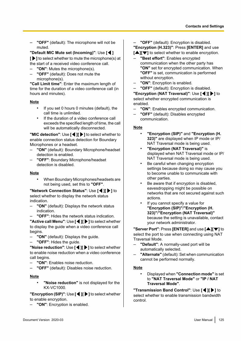
– "OFF" (default): The microphone will not bemuted.
"Default MIC Mute set (Incoming)": Use [ ][ ] to select whether to mute the microphone(s) atthe start of a received video conference call.– "ON": Mutes the microphone(s).– "OFF" (default): Does not mute the
microphone(s)."Call Limit time": Enter the maximum length oftime for the duration of a video conference call (inhours and minutes).
Note• If you set 0 hours 0 minutes (default), the
call time is unlimited.• If the duration of a video conference call
exceeds the specified length of time, the callwill be automatically disconnected.
"MIC detection": Use [ ][ ] to select whether toenable connection status detection for BoundaryMicrophones or a headset.– "ON" (default): Boundary Microphone/headset
detection is enabled.– "OFF": Boundary Microphone/headset
detection is disabled.
Note• When Boundary Microphones/headsets are
not being used, set this to "OFF"."Network Connection Status": Use [ ][ ] toselect whether to display the network statusindication.– "ON" (default): Displays the network status
indication.– "OFF": Hides the network status indication."Active call Menu": Use [ ][ ] to select whetherto display the guide when a video conference callbegins.– "ON" (default): Displays the guide.– "OFF": Hides the guide."Noise reduction": Use [ ][ ] to select whetherto enable noise reduction when a video conferencecall begins.– "ON": Enables noise reduction.– "OFF" (default): Disables noise reduction.
Note• "Noise reduction" is not displayed for the
KX-VC1000."Encryption (SIP)": Use [ ][ ] to select whetherto enable encryption.– "ON": Encryption is enabled.
– "OFF" (default): Encryption is disabled."Encryption (H.323)": Press [ENTER] and use[ ][ ] to select whether to enable encryption.– "Best effort": Enables encrypted
communication when the other party has"ON" set for encrypted communication. When"OFF" is set, communication is performedwithout encryption.
– "ON": Encryption is enabled.– "OFF" (default): Encryption is disabled."Encryption (NAT Traversal)": Use [ ][ ] toselect whether encrypted communication isenabled.– "ON": Enables encrypted communication.– "OFF" (default): Disables encrypted
communication.
Note• "Encryption (SIP)" and "Encryption (H.
323)" are displayed when IP mode or IP/NAT Traversal mode is being used.
• "Encryption (NAT Traversal)" isdisplayed when NAT Traversal mode or IP/NAT Traversal mode is being used.
• Be careful when changing encryptionsettings because doing so may cause youto become unable to communicate withother parties.
• Be aware that if encryption is disabled,eavesdropping might be possible onnetworks that are not secured against suchactions.
• If you cannot specify a value for"Encryption (SIP)"/"Encryption (H.323)"/"Encryption (NAT Traversal)"because the setting is unavailable, contactyour network administrator.
"Server Port": Press [ENTER] and use [ ][ ] toselect the port to use when connecting using NATTraversal Mode.– "Default": A normally-used port will be
automatically selected.– "Alternate" (default): Set when communication
cannot be performed normally.
Note• Displayed when "Connection mode" is set
to "NAT Traversal Mode" or "IP / NATTraversal Mode".
"Transmission Band Control": Use [ ][ ] toselect whether to enable transmission bandwidthcontrol.
Document Version 2020-03 User Manual 125
Contacts and Settings

– "ON" (default): Enables transmissionbandwidth control.
– "OFF": Disables transmission bandwidthcontrol.
Note• If "OFF" is set, other communications that
use the same network may be affected."Min. bandwidth of Video trans.": Enter theminimum bandwidth (0 kbps, 64 kbps to1500 kbps) during calls when bandwidth control isused. (Default: 0 kbps)
Note• Enter 0 to disable minimum bandwidth.
"Asymmetric TX rate": Press [ENTER] and use[ ][ ] to select the asymmetric TX rate (256 kbpsto 2.0 Mbps, default: 256 kbps)."Asymmetric TX (LAN 1)"/"Asymmetric TX (LAN2)": Press [ENTER] and use [ ][ ] to select theother party’s device used for communicating withasymmetric TX rate separate to the mediatedbandwidth.– "Not Specified" (default): Does not perform
asymmetric communication.– "HDVC+HDVC Mobile"– "HDVC Mobile"– "HDVC Mobile for Android™"– "HDVC Mobile for iOS"– "HDVC Mobile for Windows"– "HDVC"– "HDVC+HDVC Mobile for Android™"– "HDVC+HDVC Mobile for iOS"– "HDVC+HDVC Mobile for Windows"
Note• For the KX-VC1000 and KX-VC1300,
"Asymmetric TX (LAN 1)" is displayed as"Asymmetric TX".
• "Asymmetric TX (LAN 2)" can be set withthe KX-VC1600 and KX-VC2000.
• The "HDVC" selection indicates the HDVisual Communication Unit. "HDVCMobile" indicates "HDVC Mobile forAndroid™", "HDVC Mobile for iOS", and"HDVC Mobile for Windows".
• Asymmetric communication is enabledwhen SIP (when the call type is "IP Mode(SIP)" or "NAT Traversal Mode") is usedfor the communication.
• Asymmetric communications are not usedwith communications with non-Panasonicvideo conference system.
3. Press [G].• A dialogue box to confirm the saving of settings
is displayed.
4. Use [ ][ ] to select "Yes" and press [ENTER].• The system settings screen is displayed.
Setting the MCUNote
• When using a KX-VC1000 that has not beenexpanded for 4 Point Built-in MCU support,"MCU Settings" is not displayed in the systemsettings screen.
1. Select "MCU Settings" and press [ENTER].• The settings screen of the built-in MCU is
displayed.2. Use [ ][ ] to select the following items for input:
• The following items are displayed over 2 pages.To view all the items, press [R] to move to thenext page, and press [B] to move to theprevious page.
"MCU Mode": Press [ENTER] and use [ ][ ] toselect the MCU mode used when starting a videoconference.– "Discussion" (default): The same image is
displayed for the main site and sub sites. Thismode is suited to discussion-style conferences.
– "Presentation": The main site sees acomposite image including the sub sites, andthe sub sites see the image from the main siteonly. This mode is suited to lecture-styleconferences.
"Screen Layout (Discussion)": Press [ENTER]and use [ ][ ] to select the screen layout forDiscussion Mode.– "Auto" (default): Automatically changes the
layout depending on the number of partiesjoining a video conference call.
– "CP1" to "CP28": Sets the screen layoutmanually.
Note• When "Auto" is selected, the layout
changes automatically depending on thenumber of sites joining the conference.
126 User Manual Document Version 2020-03
Contacts and Settings

Number of Sites Layout Number
2 CP1
3–4 CP4
5–6 CP6
7–8 CP8
9 CP9
10 CP10
11-13 CP13
14-15 CP15
16 CP16
17-20 CP20
21 CP21
22-24 CP24
• The screen layout during a conference call canbe selected from the following 15 patterns. Thenumbers in the layout configurations indicateeach site’s image display priority.
Layout Number Layout Configuration
CP1 1
CP2 1 2
CP41 2
3 4
CP61 2
3654
Layout Number Layout Configuration
CP81
23
87654
CP9
3654987
1 2
CP101 2
3 6547 1098
CP131 2 3
654
710 11 12 13
98
CP151
2
3
84 5 6 7 913 14 1510 11 12
CP16
321 4
98765
10 11 1213 14 15 16
CP201 2
73 4 5 6 812 13 149 10 1118 19 2015 16 17
CP211
2 34 56 78 9
13 14 1510 11 1219 20 2116 17 18
Document Version 2020-03 User Manual 127
Contacts and Settings

Layout Number Layout Configuration
CP24
1 2
3 4
5 67 89 1011 12
16 17 1813 14 1522 23 2419 20 21
CP25
1
6
2
7
3 4 5
8 9 10
11 12 13 14 15
16 17 18 19 20
21 22 23 24 25
CP281
2 3 45 6 78 9 1014 15 1611 12 1320 21 2217 18 1926 27 2823 24 25
"Screen Layout (Presentation)": Press [ENTER]and use [ ][ ] to select the screen layout forPresentation Mode.– "Auto" (default): Automatically changes the
layout depending on the number of partiesjoining a video conference call.
– "CP1" to "CP28": Sets the screen layoutmanually.
Note• When "Auto" is selected, the layout
changes automatically depending on thenumber of sites joining the conference.
Number of Sites Layout Number
2 CP1
3 CP2
4–5 CP4
6–7 CP6
8–9 CP8
10 CP9
11 CP10
12-14 CP13
15-16 CP15
17 CP16
18-21 CP20
Number of Sites Layout Number
22 CP21
23-24 CP24
"Main Position (Discussion)": Press [ENTER]and use [ ][ ] to select the display method forthe main position.– "Local Site" (default): Displays your own site.– "Voice Activation 1": The site with the loudest
volume is automatically displayed as the maindisplay.
– "Voice Activation 2 (Local Site)": Your ownsite’s image is displayed as the main display,and the site with the loudest volume at the timeis displayed as display priority 2.
"Video switch time frame": Use [ ][ ] to selectthe time the screen’s display is fixed when thedisplay is controlled according to audio (1 to 20seconds, default: 10 seconds)."Site name display": Use [ ][ ] to selectwhether to display site names when the display issplit into multiple screens.– "ON" (default): Display site names.– "OFF": Do not display site names.
Note• For images displayed using HDMI 1 at the
main site, you can display the name of eachsite on the layout screen. Note, however,that when using PwithP or SideBySide forcamera or content layout, the site name isnot displayed even when using HDMI 1(Page 152).
• When using presentation mode, site namesare displayed in the composite image of subsites.
"Local Camera Display of MCU Site": Selectwhether to display an image of the main site as thecomposite image in discussion mode using [ ][ ].– "ON" (default): Displays the image of the main
site.– "OFF": Does not display the image of the main
site."Camera control transmitting": Use [ ][ ] toselect whether to allow Sub Sites to operate thecamera of main display site.– "ON": Allow camera operation by Sub Sites.– "OFF" (default): Do not allow camera operation
by Sub Sites.
128 User Manual Document Version 2020-03
Contacts and Settings

"DTMF for Content Sharing": Use [ ][ ] toselect whether to allow Sub Sites to share contentsusing remote control operations.– "ON" (default): Allow Sub Sites to perform
operations using the remote control.– "OFF": Do not allow operations by Sub Sites
using the remote control.
Note• When "ON" is set, content sharing can be
controlled using the [PC], [CAMERASUB], and [CAMERA MAIN] buttons, aswell as the numeric keypad (*10: Startsharing, *11: Stop sharing).
"DTMF layout change": Use [ ][ ] to selectwhether other parties can use remote controloperations to perform screen layout changeoperations.– "ON": Enable operations by Sub Sites using the
remote control.– "OFF" (default): Disable remote control
operations by Sub Sites."DTMF for Dial / Disconnect": Use [ ][ ] toselect whether other parties can use remote controloperations to call other sites or disconnect sitesduring calls.– "ON": Enable operations by Sub Sites using the
remote control.– "OFF" (default): Disable remote control
operations by Sub Sites."Auto move to CP1": Use [ ][ ] to selectwhether the function that switches the screen layoutto CP1 when content sharing is started is enabledor not.– "ON" (default): Switching to CP1 is enabled.– "OFF": Switching to CP1 is disabled."Other Site's Audio": Press [ENTER] and use[ ][ ] to select the mode to combine audio fromMain Site with the audio from the other site.– "Mix (Auto)" (default): Audio from the loudest
4 sites is automatically mixed together.– "Mute": Mutes the audio of Sub Sites. Only the
audio of the Main Site is output."Secondary Bandwidth Selection": Press[ENTER] and use [ ][ ] to select two types ofcommunication group thresholds.– "Not Specified": Bandwidth threshold not
considered.– "256 kbps or more" – "2.0 Mbps or
more" (default: "768 kbps or more"): Considerbandwidth to determine the two types ofcommunication group thresholds.
"Display far site's Mute icon": Use [ ][ ] toselect whether the Sub Site audio status icon isdisplayed.– "ON" (default): The audio status icon is
displayed.– "OFF": The audio status icon is not displayed."Display Presentation Mode icon": Use [ ][ ] to select whether an icon is displayed toindicate that the MCU mode is Presentation Mode.– "ON" (default): The presentation icon will be
displayed.– "OFF": The presentation icon will not be
displayed.
3. Press [G].• A dialogue box to confirm the saving of settings
is displayed.
4. Use [ ][ ] to select "Yes" and press [ENTER].• The system settings screen is displayed.
Setting One-touch ConnectionNumbersSet the addresses or profiles assigned to the one-touchconnection numbers (1 to 5) displayed on the homescreen.1. Select "One-Touch Set." and press [ENTER].
• The one-touch connection number settingsscreen is displayed.
2. Use [ ][ ] to select ""Not Registered"".
3. Press [B].• A dialogue box is displayed for selecting which
kind of input method to reference.
Note• When using a KX-VC1000 that has not
been expanded for 4 Point Built-inMCU support, the contact list selectionscreen is displayed. Proceed to "When"Contact list" is selected:" in step 4.
4. Use [ ][ ] to select the reference source,"Contact list" or "Profile" and press [ENTER].
When "Contact list" is selected:The contact list selection screen is displayed.
Document Version 2020-03 User Manual 129
Contacts and Settings

1. Use [ ][ ] to select the other party toregister, and press [ENTER].• The one-touch connection number settings
screen is displayed.
When "Profile" is selected:The profile list reference screen is displayed.1. Use [ ][ ] to select the group name you want
to register and press [ENTER].• The one-touch connection number settings
screen is displayed.
5. Press [G].• A dialogue box to confirm the saving of settings
is displayed.
6. Use [ ][ ] to select "Yes" and press [ENTER].• The system settings screen is displayed.
Making Screen StandbySettingsWhen the remote control is not operated or a videoconference call is not received for a specified length oftime, the unit enters standby mode. You can set thelength of time here.1. Select "Standby Setting" and press [ENTER].
• The screen standby settings screen isdisplayed.
2. Enter the length of time (0–99) in minutes until theunit enters screen standby mode (default: 10).
Note• If you set "0", the unit will not enter screen
standby mode automatically. However, ifyou press the remote control’s[STANDBY] button, the unit will enterscreen standby mode even if "0" is set.
3. Press [G].• A dialogue box to confirm the saving of settings
is displayed.
4. Use [ ][ ] to select "Yes" and press [ENTER].• The system settings screen is displayed.
Making Sound Settings1. Select "Sound Settings" and press [ENTER].
• The sound settings screen is displayed.
2. Use [ ][ ] to select the following items for input:"Welcome Screen Vol.": Press [ENTER] and use[ ][ ] to select the volume level ("OFF", "Low","Medium" [default] or "High") played at thestart-up."Ringback Tone Vol.": Press [ENTER] and use[ ][ ] to select the volume level ("OFF", "Low","Medium" [default] or "High") of an outgoing callring."Ring Tone Vol.": Press [ENTER] and use [ ][ ] to select the volume level ("OFF", "Low","Medium" [default] or "High") of an incoming callring."Ringback Tone": Press [ENTER] and use [ ][ ] to select the calling sound pattern ("Pattern1" to "Pattern 5") (default: "Pattern 1")."Ring Tone": Press [ENTER] and use [ ][ ] toselect the incoming call sound pattern ("Pattern1" to "Pattern 5") (default: "Pattern 1")."Default Sound Lev.": Use [ ][ ] to select thevolume level (0–20) at the start of a videoconference call (default: 16)."Sound Pre-sets": Press [ENTER] and use [ ][ ] to select the tone ("More Highs","Standard" [default], "More Lows", "Voice" or"Music") at the start of a video conference call.
Note• You can listen to a sample of the following
items by pressing [R].– "Welcome Screen Vol."– "Ringback Tone Vol."– "Ring Tone Vol."– "Ringback Tone"– "Ring Tone"
• A music note icon will be displayed to theright of the item being heard. Pressing [R]will stop the playing of the item being heard.
3. Press [G].• A dialogue box to confirm the saving of settings
is displayed.
4. Use [ ][ ] to select "Yes" and press [ENTER].• The system settings screen is displayed.
130 User Manual Document Version 2020-03
Contacts and Settings

Setting the MIC PositionYou can specify where a Digital Boundary Microphoneis conceptually positioned relative to the display. Whensounds are transmitted to another party, they are playedin accordance with the specified positions, whichcreates a stereo environment.
Note• "MIC Setting" is not displayed in the system
settings screen for the KX-VC1000.
Setting the MIC Positionautomatically1. Select "MIC Setting" and press [ENTER].
• The auto settings screen is displayed.
Note• If the manual settings screen is displayed,
press [B] to return to the auto settingsscreen.
2. Press [G].• A dialogue box to confirm the saving of settings
is displayed.
3. Use [ ][ ] to select "Yes" and press [ENTER].• The system settings screen is displayed.
Note• Depending on how many Digital Boundary
Microphones are connected, the outputsettings differ as follows:– 2 or more Digital Boundary
Microphones: Monaural output– 1 Digital Boundary Microphone: Stereo
output• When using Digital Boundary Microphones
and an Analogue Boundary Microphonetogether, the output for all BoundaryMicrophones will be monaural.
Setting the MIC Position manually1. Select "MIC Setting" and press [ENTER].
• The auto settings screen is displayed.
Note• If the manual settings screen is displayed,
proceed to step 3.
2. Press [B].• The manual settings screen is displayed.
3. Use [ ][ ] to select the Digital BoundaryMicrophone you want to configure and press[ENTER].
4. Use [ ][ ] to select the Digital BoundaryMicrophone’s relative position."Left side": Sounds on left side are played."Right side": Sounds on right side are played."Center Mono": All sounds are played throughboth the left and right speakers at the same volume."Center stereo": Sounds centred on themicrophone are played through both the left andright speakers at the same volume.
Note• When a Digital Boundary Microphone is set
to "Center stereo", make sure that it isplaced with its connector facing the display.
• When using Digital Boundary Microphonesand an Analogue Boundary Microphonetogether, the output settings differ asfollows:– Digital Boundary Microphones:
Manually set output– Analogue Boundary Microphone:
Monaural output• For the settings shown in the following
diagrams, the left/right channels aredisplayed as viewed from the side of themain video camera.
Here are examples of the relative position of DigitalBoundary Microphones.When setting Digital Boundary Microphones ina row perpendicular to the display:
Connector
Main video camera
Speaker Speaker
Display
R ch L ch
MIC 1
R ch L ch
MIC 2
R ch L ch
MIC 3
Document Version 2020-03 User Manual 131
Contacts and Settings
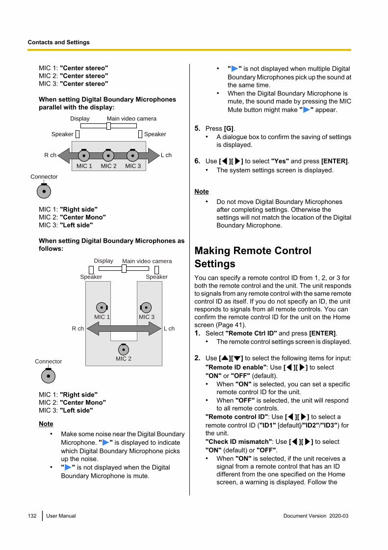
MIC 1: "Center stereo"MIC 2: "Center stereo"MIC 3: "Center stereo"
When setting Digital Boundary Microphonesparallel with the display:
Connector
Main video camera
Speaker Speaker
Display
R ch L ch
MIC 1 MIC 2 MIC 3
MIC 1: "Right side"MIC 2: "Center Mono"MIC 3: "Left side"
When setting Digital Boundary Microphones asfollows:
Main video camera
R ch L ch
MIC 2
MIC 3MIC 1
Display
Speaker Speaker
Connector
MIC 1: "Right side"MIC 2: "Center Mono"MIC 3: "Left side"
Note• Make some noise near the Digital Boundary
Microphone. " " is displayed to indicatewhich Digital Boundary Microphone picksup the noise.
• " " is not displayed when the DigitalBoundary Microphone is mute.
• " " is not displayed when multiple DigitalBoundary Microphones pick up the sound atthe same time.
• When the Digital Boundary Microphone ismute, the sound made by pressing the MICMute button might make " " appear.
5. Press [G].• A dialogue box to confirm the saving of settings
is displayed.
6. Use [ ][ ] to select "Yes" and press [ENTER].• The system settings screen is displayed.
Note• Do not move Digital Boundary Microphones
after completing settings. Otherwise thesettings will not match the location of the DigitalBoundary Microphone.
Making Remote ControlSettingsYou can specify a remote control ID from 1, 2, or 3 forboth the remote control and the unit. The unit respondsto signals from any remote control with the same remotecontrol ID as itself. If you do not specify an ID, the unitresponds to signals from all remote controls. You canconfirm the remote control ID for the unit on the Homescreen (Page 41).1. Select "Remote Ctrl ID" and press [ENTER].
• The remote control settings screen is displayed.
2. Use [ ][ ] to select the following items for input:"Remote ID enable": Use [ ][ ] to select"ON" or "OFF" (default).• When "ON" is selected, you can set a specific
remote control ID for the unit.• When "OFF" is selected, the unit will respond
to all remote controls."Remote control ID": Use [ ][ ] to select aremote control ID ("ID1" [default]/"ID2"/"ID3") forthe unit."Check ID mismatch": Use [ ][ ] to select"ON" (default) or "OFF".• When "ON" is selected, if the unit receives a
signal from a remote control that has an IDdifferent from the one specified on the Homescreen, a warning is displayed. Follow the
132 User Manual Document Version 2020-03
Contacts and Settings

procedures on the screen to change the remotecontrol ID.
• When "OFF" is selected, even if the unitreceives a signal from a remote control that hasan ID different from the one specified, nowarning is displayed on the Home screen.
Note• If multiple remote controls with assigned
IDs are being used close together, it isrecommended that you select "OFF" for"Check ID mismatch".
3. Press [G].• A dialogue box to confirm the saving of settings
is displayed.
4. Use [ ][ ] to select "Yes" and press [ENTER].
5. When "Remote ID enable" is set to "ON":The dialogue box for changing the ID of the remotecontrol is displayed. Proceed to step 6.
Note• While the dialogue box is displayed, video
conference calls cannot be received.
When "Remote ID enable" is set to "OFF":The system settings screen is displayed. Press[HOME] to return to the Home screen.
6. Use the following procedure to change the ID of theremote control.1. Press and hold [·] and [#] at the same time.2. Within 2 seconds after you release the buttons,
press the number (1 to 3) corresponding to theID that you specified for "Remote control ID"in step 1.– 1: ID1– 2: ID2– 3: ID3
7. Press [ENTER].• The dialogue box disappears and the remote
control ID of the unit will be saved.
Note• If the dialogue box does not disappear,
repeat the procedure above, several timesif necessary. If the dialogue box still doesnot disappear, turn the power off and thenback on to cancel the settings. For details,contact your dealer.
Changing Video CameraSettings1. Select "Camera Settings" and press [ENTER].
• The video camera settings screen is displayed.
2. Use [ ][ ] to select the following items for input:"CAM ctrl from remote site(s)": Use [ ][ ] toselect whether to allow the other party to controlyour video camera.– "ON": Allows the other party to control your
video camera.– "OFF" (default): Prevents the other party from
controlling your video camera."Direct Cam Ctrl during call": Use [ ][ ] toselect whether camera operation by remote controlis enabled during a video conference call.– "ON" (default): Allow camera operations using
the remote control.– "OFF": Do not allow camera operations using
the remote control."Direct Cam Ctrl on Home Screen": Use [ ][ ] to select whether camera operation by remotecontrol is enabled when not in a video conferencecall.– "ON" (default): Allow camera operations using
the remote control.– "OFF": Do not allow camera operations using
the remote control."Pan Direction": Use [ ][ ] to select thedirection in which the video camera will move whenthe buttons on the remote control are pressed.– "Normal" (default): The video camera will
move in the left/right direction, as viewed fromthe video camera.
– "Reversed": The video camera will move in theleft/right direction, as viewed from the subject.
"Remote control through function": Use [ ][ ] to select whether the camera or the unit willreceive commands from the remote control.– "ON": The camera will receive commands from
the remote control.– "OFF" (default): The unit will receive
commands from the remote control.
Note• For software versions lower than 4.50,
"Remote control through function" is
Document Version 2020-03 User Manual 133
Contacts and Settings
displayed as "FIX Cam's Remote CtrlRcvr".
• If a camera is not connected or dependingon the model of the camera, the unit willreceive commands from the remote controleven if "ON" is selected.
"Layout change camera control": Use [ ][ ] toselect whether the layout will change while thecamera is being controlled.– "ON": The layout will change.– "OFF" (default): The layout will not change.
3. Press [G].• A dialogue box to confirm the saving of settings
is displayed.
4. Use [ ][ ] to select "Yes" and press [ENTER].• The system settings screen is displayed.
Making Language Settings1. Select "Language Setting" and press [ENTER].
• The language settings screen is displayed.
2. Press [ENTER] and use [ ][ ] to select thedesired language.
Note• The language you can select is as follows:
"English": English (default), "Deutsch":German, "Français": French, "Italiano":Italian, "Español": Spanish,"Nederlands": Dutch, "Português":Portuguese, " ": Japanese,"Русскийязык": Russian, " "" ": Chinese, " ": Arabic.
• When " " is selected, Arabic isdisplayed as "Arabic" after the language ischanged.
• When " " is selected, some of thelanguage selections will be displayed asfollows after the language is changed:French: "French", Spanish: "Spanish",Russian: "Russian", Arabic: "Arabic"
3. Press [ENTER].
4. Press [G].• A dialogue box to confirm the saving of settings
is displayed.
5. Use [ ][ ] to select "Yes" and press [ENTER].When the language is changed to " "When the language is changed from " "• The unit restarts automatically.Languages apart from the above• The system settings screen is displayed in the
selected language.
Note• If you accidentally choose the wrong
language, follow the steps below to changethe language setting.1. Press [HOME].2. Press [MENU].3. Press [ ] four times to select the fifth
item from the top, press [ENTER].4. Press [ ] twice.
• The second page is displayed.5. Press [ ] to select the second item
from the top, press [ENTER].• The language settings screen is
displayed.6. Repeat the procedure from step 2.
Making Recording SettingsYou can set the USB recording settings during calls,while idle, and during a multicast. You can also start andstop recording while idle.
Note• You can make settings only when "USB Rec"
in "Security Settings" is set to "ON".• The screen recorded in KX-VC2000 differs from
KX-VC1000, KX-VC1300 and KX-VC1600. Fordetails about recording, refer to "Using USBRecording Features (Page 187)".
To change settings
Note• You cannot change settings while recording.
The unit records according to the settingsdisplayed on the settings screen whilerecording.
1. Select "USB Rec Settings" and press [ENTER].• The recording settings screen is displayed.
2. Use [ ][ ] to select the following items for input.
134 User Manual Document Version 2020-03
Contacts and Settings

"Video Quality": Press [ENTER] and use [ ][ ] to select "High", "Medium" (default), or"Low"."Dual Display Rec screen": Press [ENTER] anduse [ ][ ] to select "HDMI 1" (default) or "HDMI2".
Note• You can make settings only when "Video
Output" in "Video Output" is set to "HDMI1 / HDMI 2" (Page 152).
"Display Rec Status icon": Use [ ][ ] to selectwhether to display the icon that indicates the unit isrecording in the icon display area.– "ON" (default): Displays the icon.– "OFF": Does not display the icon.
3. Press [G].• The dialogue box to confirm saving the settings
is displayed.
Note• If you proceed to step 2 in "To start and stop
recording" without performing step 3, youcan start recording with the changedsettings. The changed settings are notsaved, and when you stop recording, thesettings return to the state before thechanges.
4. Use [ ][ ] to select "Yes" and press [ENTER].• The system settings screen is displayed.
To start and stop recording1. Select "USB Rec Settings" and press [ENTER].
• The recording settings screen is displayed.2. Use [ ][ ] to select "USB Rec" and press
[ENTER].When not recording: The dialogue box to confirmwhether to start recording is displayed. Use [ ][ ] to select "Yes" or "No" and press [ENTER]– Selecting "Yes" starts recording.– Selecting "No" does not start recording.When recording: The dialogue box to confirmwhether to stop recording is displayed. Use [ ][ ] to select "Yes" or "No" and press [ENTER]– Selecting "Yes" stops recording.– Selecting "No" does not stop recording.
Note• When you stop recording, do not remove
the USB memory device until the recordingcomplete dialogue box is displayed.
Setting the USB Device ModeYou can switch to USB host mode and USB DeviceMode.USB Host Mode: Connect a USB memory device to theUSB jack to import or export data, update software, orperform USB recording.USB Device Mode: Connect a computer to the USBjack to use this unit's camera and microphone with thecomputer.
Note• You can make settings when "PC Peripheral"
is enabled in "Enhancement".• Cannot be set while using Web Hybrid Mode.• When using USB Device Mode, make sure to
use the proprietary USB conversion cable.• You cannot communicate with other sites while
in USB Device Mode (while "USB DeviceMode" is set to "ON (Permanent)" or "ON(Temporary)" in step 2).
• For details about USB Device Mode, refer to"Using USB Device Mode (Page 190)".
1. Select "USB Device Mode" and press [ENTER].• The USB Device Mode settings screen is
displayed.2. Use [ ][ ] to select the following items for input.
"USB Device Mode": Press [ENTER] and use[ ][ ] to select whether to enable USB DeviceMode.– "OFF" (default): Disables USB Device Mode
and uses USB host mode.– "ON (Permanent)": Enables USB Device
Mode. Stays enabled even if the unit isrestarted.
– "ON (Temporary)": Enables USB DeviceMode. When the unit is restarted, "OFF" isautomatically selected and the unit returns toUSB host mode.
Note• When "ON (Permanent)" is changed to
"ON (Temporary)", or "ON (Temporary)"is changed to "ON (Permanent)",temporarily set to "OFF".
"Video Quality": When the unit's video frequencyis 50 HzPress [ENTER] and use [ ][ ] to select"640x480 (Max. 25 fps)" (default) or"1280x720 (Max. 12.5 fps)".When the unit's video frequency is 60 Hz
Document Version 2020-03 User Manual 135
Contacts and Settings

Press [ENTER] and use [ ][ ] to select"640x480 (Max. 30 fps)" (default) or"1280x720 (Max. 15 fps)"."Display USB Device Mode icon": Use [ ][ ]to select whether to display the icon that indicatesthe unit is in USB Device Mode in the icon displayarea.– "ON" (default): Displays the icon.– "OFF": Does not display the icon.
Note• Can be set when "USB Device Mode" is
set to "OFF".3. Press [G].
If "USB Device Mode" was changed from "OFF"to "ON (Permanent)", or from "OFF" to "ON(Temporary)"• The dialogue box to confirm saving the settings
and switching the mode is displayed. When youuse [ ][ ] to select "Yes" and press[ENTER], the USB Device Mode switches andthe Home screen is displayed.
Note• To display the computer screen on a TV
connected to the unit, press [PC].• The audio input during USB Device Mode is
the same as when "HDMI Audio input /content" (Page 154) is set to "PC".
For all other cases• The dialogue box to confirm saving the settings
is displayed. When you use [ ][ ] to select"Yes" and press [ENTER], the system settingsscreen is displayed.
Note• When you set "Display USB Device Mode
icon" to "ON", is displayed at the
A position during USB Device Mode.
A
Setting the Web Hybrid ModeYou can switch to USB host mode (Page 135) and WebHybrid Mode.Web Hybrid Mode: Interconnects HD VisualCommunication Unit video conferences and webconferences using general conference applicationsinstalled on a computer and shares the audio of thevideo conferences and the video and audio of the webconferences.
Note• Can be set when "Web Hybrid Mode" is
enabled in "Enhancement".• Cannot be set while using USB Device Mode.• When using Web Hybrid Mode, make sure to
use the proprietary USB conversion cable.• For details about Web Hybrid Mode, refer to
"Using Web Hybrid Mode (Page 192)".
Setting the Web Hybrid Mode1. Select "Web Hybrid Mode" and press [ENTER].
• The Web Hybrid Mode settings screen isdisplayed.
2. Use [ ][ ] to select the following items for input."Web Hybrid Mode": Press [ENTER] and use[ ][ ] to select whether to enable Web HybridMode.– "OFF" (default): Disables Web Hybrid Mode
and uses USB host mode.– "ON (Permanent)": Enables Web Hybrid
Mode. Stays enabled even if the unit isrestarted.
– "ON (Temporary)": Enables Web HybridMode. When the unit is restarted, "OFF" isautomatically selected and the unit returns toUSB host mode.
Note• When "ON (Permanent)" is changed to
"ON (Temporary)", or "ON (Temporary)"is changed to "ON (Permanent)",temporarily set to "OFF".
"Display Web Hybrid Mode icon": Use [ ][ ]to select whether to display the icon that indicatesthe unit is in Web Hybrid Mode in the icon displayarea.– "ON" (default): Displays the icon.– "OFF": Does not display the icon.
Note• Can be set when "Web Hybrid Mode" is
set to "OFF".
136 User Manual Document Version 2020-03
Contacts and Settings
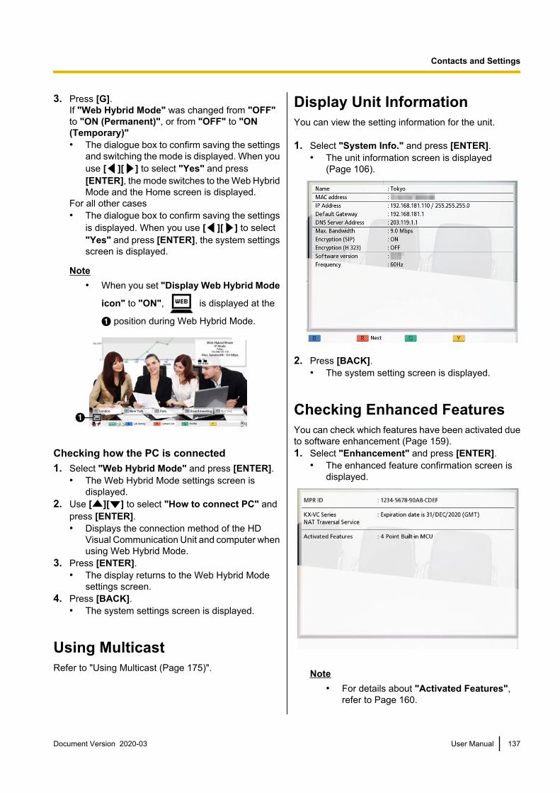
3. Press [G].If "Web Hybrid Mode" was changed from "OFF"to "ON (Permanent)", or from "OFF" to "ON(Temporary)"• The dialogue box to confirm saving the settings
and switching the mode is displayed. When youuse [ ][ ] to select "Yes" and press[ENTER], the mode switches to the Web HybridMode and the Home screen is displayed.
For all other cases• The dialogue box to confirm saving the settings
is displayed. When you use [ ][ ] to select"Yes" and press [ENTER], the system settingsscreen is displayed.
Note• When you set "Display Web Hybrid Mode
icon" to "ON", is displayed at the
A position during Web Hybrid Mode.
A
Checking how the PC is connected1. Select "Web Hybrid Mode" and press [ENTER].
• The Web Hybrid Mode settings screen isdisplayed.
2. Use [ ][ ] to select "How to connect PC" andpress [ENTER].• Displays the connection method of the HD
Visual Communication Unit and computer whenusing Web Hybrid Mode.
3. Press [ENTER].• The display returns to the Web Hybrid Mode
settings screen.4. Press [BACK].
• The system settings screen is displayed.
Using MulticastRefer to "Using Multicast (Page 175)".
Display Unit InformationYou can view the setting information for the unit.
1. Select "System Info." and press [ENTER].• The unit information screen is displayed
(Page 106).
2. Press [BACK].• The system setting screen is displayed.
Checking Enhanced FeaturesYou can check which features have been activated dueto software enhancement (Page 159).1. Select "Enhancement" and press [ENTER].
• The enhanced feature confirmation screen isdisplayed.
Note• For details about "Activated Features",
refer to Page 160.
Document Version 2020-03 User Manual 137
Contacts and Settings

2. Press [BACK].• The system setting screen is displayed.
Performing a Network TestYou can confirm whether a network connection can beestablished with a particular IP address.
Note• You cannot perform a network test from the
contact list screen or the call history screen.1. Select "Network Test" and press [ENTER].
• The network test screen is displayed.
2. Enter an IP address.
Note• If an IPv4 address contains 1 or 2 digit
numbers, enter these numbers as they are.Do not enter like [.001].Example: The IP address is [192.168.0.1].– Correct entry: [192.168.0.1]– Wrong entry: [192.168.000.001]
• For the input format when an IPv6 addressis used, refer to Page 47.
• Host names cannot be entered.
3. Press [R].• The network test starts. After the network test is
finished, if the network test was successful ortimed out, the details of the results aredisplayed. If the network test failed, a messageindicating the failure is displayed.
4. Press [BACK].• The system setting screen is displayed.
Performing Self DiagnosisYou can check how your image will be displayed andhow your voice will be heard to the other party beforestarting a video conference call, using your own displayand speakers.
Note• Self diagnosis can be performed even when a
headset is connected.1. Select "Self Diag." and press [ENTER].
• The self diagnosis screen is displayed with thedialogue box.
Note• You can hide or display the dialogue box by
pressing [B].• Set the microphone at least 1 m (3.3 ft)
away from the speakers.
2. Press [R].• The self diagnosis starts.
Note• Check the image that is displayed from the
main video camera.• To avoid feedback, slowly raise the volume
using the remote control’s [+] button.• When someone speaks into the
microphone, confirm whether the soundplays back through the speakers.
• During self diagnosis, all BoundaryMicrophones will be set to "Centerstereo".
• During self diagnosis, the tone will be set to"Standard".
3. Press [R].• The self diagnosis ends.
Note• If you do not press [R], the self diagnosis
will automatically end after about10 minutes.
4. Press [BACK].• The system setting screen is displayed.
Displaying the LicenceInformationYou can display information about the licence and OpenSource Software.1. Select "License Info." and press [ENTER].
• The licence information display screen isdisplayed.
• Press [R] to move to the next page, and press[B] to move to the previous page.
2. Press [BACK].• The system setting screen is displayed.
138 User Manual Document Version 2020-03
Contacts and Settings

Displaying the End-UserLicence AgreementYou can display information about the End-UserLicence Agreement.1. Select "EULA" and press [ENTER].
• The End-User Licence Agreement displayscreen is displayed.
2. Press [BACK].• The system setting screen is displayed.
Performing RemoteMaintenanceThe following operation is for performing remotemaintenance by your dealer. After performing theoperation, you cannot use the unit until remotemaintenance is finished. However, turning the power offand then back on cancels remote maintenance, and youcan use the unit. For details, contact your dealer.1. Select "Remote access" and press [ENTER].
• The dialogue box confirming whether you wantto start remote maintenance is displayed.
2. Use [ ][ ] to select "Yes" and press [ENTER].• The remote maintenance screen is displayed.
Document Version 2020-03 User Manual 139
Contacts and Settings

Making Administrator Menu Settings
Administrator Menu ListYou can set, change, and confirm the unit’s administrator functions.
Note• If a video conference call is received while data is being entered, a dialogue box to confirm if you answer
a video conference call is displayed.Use [ ][ ] to select "Yes" or "No" and press [ENTER].• When "Yes" is selected, you can answer a video conference call while any unsaved data is lost.• When "No" is selected, you can continue entering the data.
1. Press [MENU].• The Menu screen is displayed.
2. Use [ ][ ] to select "Settings" and press [ENTER].• The system settings screen is displayed.
3. Press [ ][ ] to display the fourth page.
4. Use [ ][ ] to select "Admin login" and press [ENTER].• The login screen is displayed.
140 User Manual Document Version 2020-03
Contacts and Settings

5. Use [ ][ ] to select "Password", then enter the administrator password (4–10 digits).
Note• You can display the login screen by pressing [Y] in the Menu screen instead of performing steps
1–4.• Please enter the administrator password that was set during installation.• If you forget the administrator password, please contact your dealer.
6. Use [ ][ ] to select "Login" and press [ENTER].• The Administrator Menu List is displayed.
Administrator Menu Screen ListA Password Settings:
Sets the unit’s administrator password (Page 144).
B Encryption:Sets the use of encryptedcommunications and users, etc. (Page 144).
C Update Settings:Performs the settings for confirming thelatest version before performing asoftware update (Page 145).
D Connection mode:Sets the mode for communicating withthe other party (Page 146).
E NAT Settings:Sets NAT information (Page 146).
Previouspage
[ ] [ ]Following
page
[B] [R]
F Call Type Settings:Sets the communication types used bythe unit (Page 147).
G SIP Settings:Sets SIP settings (Page 148).
H H.323 Settings:Sets H.323 settings (Page 149).
I Codec Settings:Sets the enabling/disabling of codecs (Page 150).
J Security Settings:Sets settings such as call denied and callhistory (page 150).
Document Version 2020-03 User Manual 141
Contacts and Settings

Previouspage
[ ] [ ]Following
page
[B] [R]
K Video Output:Sets HDMI and analogue componentvideo output (Page 152).
L Audio I/O:Sets audio settings (Page 154).
M GUI Settings:Sets which items are displayed on themenu screens and other screens (Page 155).
N HDMI Settings:Sets the enabling/disabling of control viaHDMI (Page 156).
O Power Settings:Sets automatic power on and off (Page 156).
Previouspage
[ ] [ ]Following
page
[B] [R]
P Shortcut Settings:Sets the shortcut function where theremote control’s colour keys can be setto display screens such as the networksettings screen (Page 157).
Q Select local site set:Sets local site settings (Page 158).
R Multicast Tree Set.:Sets the multicast function settings (Page 178).
S Contact transfer:Performs settings for sharing contactlists with multiple sites (Page 158).
Previouspage
[ ] [ ]Following
page
[B] [R]
142 User Manual Document Version 2020-03
Contacts and Settings

T Enhancement:Activates registration keys used forenhancing the features of the device (Page 159).
U Software update:Updates the software from a USBmemory device (Page 160).
V Camera Initialize:Initialises your own site’s video camera (Page 162).
W System Initialize:Initialises all settings apart from those forfunctions enabled from enhancedsoftware (Page 162).
X Remote access Set.:Sets the settings required to remotelyaccess the unit (Page 162).
Previouspage
[ ] [ ]Following
page
[B] [R]
Y Export data:Exports information from the contact list,etc. (Page 163).
Z Import data:Imports exported data from a USBmemory device (Page 164).
7. Use [ ][ ] to select the items for input and press [ENTER].• The selected screen is displayed. Perform settings following the descriptions of each screen (A
through Z).8. Press [HOME].
• The Home screen is displayed.
Document Version 2020-03 User Manual 143
Contacts and Settings

Making AdministratorPassword Settings1. Select "Password Settings" and press [ENTER].
• The password settings screen is displayed.
2. Use [ ][ ] to select the following items and entera password (4–10 digits):"Current password": Enter the current password(default: 00000000)."New password": Enter the new password."Retype new password": Enter the new passwordagain.
Note• Please change the default login password
the first time the unit is installed.• Be sure to keep the password safe.
3. Press [G].• A dialogue box to confirm the changing of
settings is displayed.
4. Use [ ][ ] to select "Yes" and press [ENTER].• The administrator menu screen is displayed.
Making Encryption SettingsNote
• For 2-party video conference calls, aconnection cannot be made if the two party’ssettings for communication encryption do notmatch. However, when communication isperformed using H.323, and either site has"Best effort" set for "Encryption (H.323)", aconnection can be made even if the sites’communication encryption settings are not thesame. For multiple-party video conferencecalls, the ability for the Main Site to connect toSub Sites is determined the same way as for2-party video conference calls.
• Be careful when changing encryption settingsbecause doing so may cause you to becomeunable to communicate with other parties.
• There is a danger that encryption settings willbe changed by a third party. Therefore, becareful when managing the administratorpassword and giving users the authority tochange encryption settings.
• If an encryption key is not set for SIPcommunication, you cannot enable encryption.
• When using encrypted communication with theKX-VC Series NAT Traversal Service, set SIPcommunication encryption using this setting.When using IP/NAT traversal mode, use thesame encryption settings as for SIPcommunication in IP mode or NAT traversalmode.
• Be aware that if encryption is disabled,eavesdropping might be possible on networksthat are not secured against such actions.
1. Select "Encryption" and press [ENTER].• The encryption settings screen is displayed.
2. Use [ ][ ] to select the following items for input:
Note• When using IP mode:
– When "SIP" is set to "OFF" on the calltype settings screen (Page 147),"Access mode (SIP)", "Encryption(SIP)" and "Encryption Key (SIP)"cannot be set.
– When "H.323" is set to "OFF" on thecall type settings screen (Page 147),"Access mode (H.323)" and"Encryption (H.323)" cannot be set.
– "Access mode (NAT Traversal)" and"Encryption (NAT Traversal)" cannotbe set.
• When using NAT Traversal mode:– "Access mode (SIP)", "Encryption
(SIP)", "Access mode (H.323)", and"Encryption (H.323)" cannot be set.
• When using IP/NAT Traversal mode:– When "H.323" is set to "OFF" on the
call type settings screen (Page 147),"Access mode (H.323)" and"Encryption (H.323)" cannot be set.
• "Encryption (SIP)", "Encryption (NATTraversal)", and "Encryption (H.323)"can be set when "Admin" is set to each of"Access mode (SIP)", "Access mode(NAT Traversal)" and "Access mode (H.323)".
"Access mode (SIP)"/"Access mode (NATTraversal)"/"Access mode (H.323)": Use [ ][ ] to select "Admin" (default) or "User".• When "Admin" is selected, only the network
administrator can enable/disable encryption.• When "User" is selected, any users can
enable/disable encryption with each of
144 User Manual Document Version 2020-03
Contacts and Settings

"Encryption (SIP)" (Page 125), "Encryption(H.323)" (Page 125), and "Encryption (NATTraversal)" (Page 125).
"Encryption (SIP)"/"Encryption (NATTraversal)": Use [ ][ ] to select whether toenable encryption.– "ON": Encryption is enabled.– "OFF" (default): Encryption is disabled."Encryption Key (SIP)": Enter an encryption key(4 to 256 characters [alphanumeric, space,symbols]) (Page 196).
Note• &, <, >, comma (,), double quotation mark
(") cannot be entered.• While being entered, the characters of the
encryption key are displayed, but once thesettings are saved, all the characters will bedisplayed as asterisks (*), and you will nolonger be able to check the encryption keyon the screen. Record the encryption keybeforehand, and store it in a safe location.
• If the value specified in "Encryption Key(SIP)" does not match the other party’s, thevideo conference call will not start even ifencryption is enabled.
• When the encryption key is displayed asasterisks (*), pressing [Y] deletes the entireencryption key.
• The name of "Encryption Key (SIP)"changes depending on the connectionmode.– When IP mode is used: "Encryption
Key (SIP)"– When using NAT Traversal mode:
"Encryption Key (NAT Traversal)"– When using IP/NAT Traversal mode:
"Encryption Key (SIP / NAT Trav.)""Encryption (H.323)": Press [ENTER] and use[ ][ ] to select whether to enable encryption.– "Best effort": enables encrypted
communication when the other party hasenabled encrypted communication. Whendisabled, communication is performed withoutencryption.
– "ON": Encryption is enabled.– "OFF" (default): Encryption is disabled.
3. Press [G].• A dialogue box to confirm the saving of settings
is displayed.
4. Use [ ][ ] to select "Yes" and press [ENTER].• The administrator menu screen is displayed.
Making Software UpdateSettingsPreparation settings for updating the software can bemade here.
Note• The DNS server setting is necessary to check
for upgrades and to download the latestsoftware from the network (Page 120).
1. Select "Update Settings" and press [ENTER].• The update settings screen is displayed.
2. Use [ ][ ] to select the following items for input:"Proxy Server Address": Enter the IP address ofthe proxy server.
Note• IPv6 addresses and host names cannot be
used for setting.• If the IP address contains 1 or 2 digit
numbers, enter these numbers as they are.Do not enter like [.001].Example: The IP address is [192.168.0.1].– Correct entry: [192.168.0.1]– Wrong entry: [192.168.000.001]
"Proxy Server Port": Enter the proxy server portnumber (1–65535)."Automatic Version Check": Use [ ][ ] toselect "ON" or "OFF" (default).• When "ON" is selected, the unit will
automatically look up the DNS server or proxyserver to see if there are updates for yoursoftware on start-up. If updates are available, adialogue box is displayed on the Home screen.
• When "OFF" is selected, the unit will notautomatically look up the DNS server or proxyserver to see if there are updates for yoursoftware on start-up.
3. Press [G].• A dialogue box to confirm the saving of settings
is displayed.
4. Use [ ][ ] to select "Yes" and press [ENTER].• The administrator menu screen is displayed.
Document Version 2020-03 User Manual 145
Contacts and Settings

Making Connection ModeSettings1. Select "Connection mode" and press [ENTER].
• The connection mode setting screen isdisplayed.
2. Press [ENTER], use [ ][ ] to select the desiredconnection mode, and then press [ENTER] again."IP Mode": Communication is established over theInternet or an intranet."NAT Traversal Mode": Communication isestablished using KX-VC Series NAT TraversalService."IP / NAT Traversal Mode": Performscommunication using the 2 modes of IP Mode andNAT Traversal Mode.
Note• Communication cannot be established with
a party whose connection mode settingdiffers from yours.
• "NAT Traversal Mode" can be used onlyafter activating KX-VC Series NATTraversal Service with an activation key.For details about KX-VC Series NATTraversal Service, refer to the following website:https://panasonic.net/cns/psn/products/hdvc/nat/nat_traversal/index.html
3. Press [G].• A dialogue box to confirm the saving of settings
and system restart after saving is displayed.
4. Use [ ][ ] to select "Yes" and press [ENTER].• The system will automatically restart to reflect
changes to system settings.
Note• When changing the connection mode, the time
required for a restart may depend on networkconditions.
Making NAT SettingsNote
• To change the static NAT settings, it isnecessary to configure system settings,
including the port number settings. For details,contact your dealer.
• When using IP mode (Page 146), "NAT" is notdisplayed in step 2.
• When using NAT traversal mode (Page 146),"Static NAT", "WAN IP Address", and "Localaddress judgement" are not displayed in step2.
• This setting is available only when "IP Address(LAN 1)" (setting) is set to "Manual" in"Network Settings" (Page 120).
• Depending on the model you are using, theavailable settings for "RTP and RTCP forAudio", "RTP and RTCP for Video", "CameraControl", "RTP and RTCP for Video (Sub)","BFCP", and "H.245" differ. The availablesettings are written in the order of KX-VC2000,KX-VC1600, and then KX-VC1300/KX-VC1000.
1. Select "NAT Settings" and press [ENTER].• The NAT settings screen is displayed.
2. Use [ ][ ] to select the following items for input:• The following items are displayed over 2 pages.
To view all the items, press [R] to move to thenext page, and press [B] to move to theprevious page.
• If the settings have been changed, press [G]before changing to a different screen to savethe settings.
"NAT": Press [ENTER] and use [ ][ ] to select"Dynamic" (default) or "Static"."Static NAT": Use [ ][ ] to select "ON" or"OFF" (default).
Note• To select "ON", "H.460" must be set to
"OFF" on the H.323 settings screen(Page 149).
• When "ON" is selected, the IP address ofthe WAN side will be displayed for the unitinformation on the Home screen (Page 41).
"WAN IP Address": Enter the WAN IP address ofthe router.
Note• IPv6 addresses cannot be used for setting.• If the IP address contains 1 or 2 digit
numbers, enter these numbers as they are.Do not enter like [.001].Example: The IP address is [192.168.0.1].– Correct entry: [192.168.0.1]– Wrong entry: [192.168.000.001]
146 User Manual Document Version 2020-03
Contacts and Settings

• If "Obtain automatically" is displayed, theWAN IP address cannot be set. For details,contact your dealer.
"Local address judgement": Press [ENTER] anduse [ ][ ] to select "OFF" (default) or "Auto".– "OFF" (default): Static NAT is applied to all
addresses.– "Auto": Static NAT is not applied to private
addresses."Conversion IP and Port Num.": Use [ ][ ] toselect "ON" or "OFF" (default).
Note• When using a router that features
Symmetric NAT to connect to a mobiledevice, select "ON".
• When "ON" is selected, configure staticNAT settings for the unit and the router thatthe unit is connected to.
"RTP and RTCP for Audio": Enter the initial portnumber (5100–5108, 5100–5164, 5100–5188) forRTP and RTCP for Audio (default: 5100)."RTP and RTCP for Video": Enter the initial portnumber (5200–5208, 5200–5264, 5200–5288) forRTP and RTCP for Video (default: 5200)."Camera Control": Enter the initial port number(5300–5308, 5300–5364, 5300–5388) forcontrolling a video camera (default: 5300)."RTP and RTCP for Video (Sub)": Input the subimage RTP/RTCP port number (5400–5408, 5400–5464, 5400–5488). (default: 5400)"BFCP": Input the BFCP initial port number (5800–5876, 5800–5890, 5800–5895). (default: 5800)"SIP": Enter the port number for 2-party videoconference calls (5000–5099) for communicationusing a SIP server (default: 5060).
Note• The changed port number will be displayed
on the unit information screen (Page 106)."H.245": Enter the initial port number for H.245(5500–5550, 5500–5580, 5500–5590) (default:5500).
Note• For the following items, a number will be
automatically added to the initial portnumber that you enter. The total numberindicates the range and values of availableport numbers for the items.– "RTP and RTCP for Audio"– "RTP and RTCP for Video"– "Camera Control"
– "RTP and RTCP for Video (Sub)"– "BFCP"– "H.245"
3. Press [G].• A dialogue box to confirm the saving of settings
is displayed.
4. Use [ ][ ] to select "Yes" and press [ENTER].• The administrator menu screen is displayed.
Making Call Type Settings1. Select "Call Type Settings" and press [ENTER].
• The call type settings screen is displayed.
2. Use [ ][ ] to select the following items for input:"SIP": Use [ ][ ] to select "ON" (default) or"OFF".
Note• When "OFF" is selected, you cannot use a
SIP server even if "ON" is set to "SIPServer" (Page 148).
• If the other party is using the KX-VC300 orKX-VC600 with a software version olderthan 3.00 (not including 3.00), you cannotmake a video conference call using H.323.You must select "ON".
"H.323": Use [ ][ ] to select "ON" (default) or"OFF".
Note• When "OFF" is selected, you cannot use a
gatekeeper and H.460 even if "ON" isselected for "Gatekeeper" and "H.460" (Page 149).
"Priority for connection mode": Press [ENTER]and use [ ][ ] to select "IP Mode(SIP)" (default), "IP Mode (H.323)", or "NATTraversal Mode".
Note• The communication type selected here will
be reflected onto the device’s settings suchas its displayed contents and defaultconnection mode values for making calls.
3. Press [G].• A dialogue box to confirm the saving of settings
is displayed.
Document Version 2020-03 User Manual 147
Contacts and Settings

4. Use [ ][ ] to select "Yes" and press [ENTER].• The administrator menu screen is displayed.
Making SIP SettingsWhen using a SIP server over an intranet, videoconference calls can be made using SIP URIs (SIP username@SIP domain name).
Note• These settings can only be made when "SIP"
is set to "ON" on the call type settings screen.• Video conference calls to an MCU or a
non-Panasonic video conference systemthrough a SIP server using a SIP URI are notguaranteed.
• When connecting to an MCU by entering theMCU’s conference room number@IP address,"SIP Server" and "Gatekeeper" (Page 149)must be set to "OFF".
• If video conference calls cannot be madebecause there is a problem with the SIP server,the SIP settings are incorrect (on the server, oron the unit), etc., "Not registered" will bedisplayed on the Home screen instead of theSIP user name. In this case, you cannot makecalls using either IP addresses or SIP. Contactyour network administrator.
1. Select "SIP Settings" and press [ENTER].• The SIP setting screen is displayed.
2. Use [ ][ ] to select the following items for input:"SIP Server": Use [ ][ ] to select "ON" or"OFF" (default).
Note• To communicate using a SIP server, "ON"
must be selected and "SIP ServerAddress", "SIP Username", and "SIPDomain Name" must be set.
• To select "ON", "Gatekeeper" (Page 149)must be set to "OFF".
"SIP Server Address": Enter the SIP server’s IPaddress (or host name).
Note• If an IPv4 address contains 1 or 2 digit
numbers, enter these numbers as they are.Do not enter like [.001].Example: The IP address is [192.168.0.1].– Correct entry: [192.168.0.1]
– Wrong entry: [192.168.000.001]• For the input format when an IPv6 address
is used, refer to Page 47.• The DNS server setting is necessary to
enter host names (Page 120).• See Page 47 for details about the
characters that can be input for host names."SIP Username": Enter the SIP user name."SIP Domain Name": Enter the SIP domain name.
Note• See Page 47 for details about the
characters that can be input.• Enter a standards-compliant value. For
details, contact your network administrator."Digest Authentication": Use [ ][ ] to selectwhether to enable digest authentication.– "ON": Enables digest authentication.– "OFF" (default): Disables digest authentication."Authentication ID": Enter an authentication ID(1–60 characters [alphanumeric, space, symbols])(Page 196). &, <, >, comma (,), double quotationmark (") cannot be entered."Authentication Password": Enter anauthentication password (0–60 characters[alphanumeric, space, symbols]) (Page 196). &, <,>, comma (,), double quotation mark (") cannot beentered.
Note• To communicate using a SIP server, it may
be necessary to set "DigestAuthentication", "Authentication ID",and "Authentication Password". Fordetails, contact your network administrator.
• "Authentication ID" and "AuthenticationPassword" can only be set when "DigestAuthentication" is set to "ON".
• While being entered, the characters of theauthentication password are displayed, butonce the settings are saved, all thecharacters will be displayed as asterisks (*),and you will no longer be able to check theauthentication password on the screen.Record the authentication passwordbeforehand, and store it in a safe location.
• When the authentication password isdisplayed as asterisks (*), pressing [Y]deletes the entire authentication password.
"SIP Transport Protocol": Press [ENTER] andthen use [ ][ ] to select between protocols(UDP, TCP, Auto (Switch by Site), or Auto (TCP /UDP) [default]) used when communicating via SIP.
148 User Manual Document Version 2020-03
Contacts and Settings

Note• When Auto (Switch by Site) is selected,
TCP will be used if using a SIP server, andUDP will be used if not using a SIP server.When Auto (TCP / UDP) is selected,communication will be attempted in order ofTCP and then UDP. Normally, select Auto(TCP / UDP).
3. Press [G].• A dialogue box to confirm the saving of settings
is displayed.
4. Use [ ][ ] to select "Yes" and press [ENTER].• The administrator menu screen is displayed.
Making H.323 SettingsNote
• These settings can only be made when "H.323" is set to "ON" on the call type settingsscreen.
• When connecting to an MCU by entering theMCU’s conference room number@IP address,"SIP Server" (Page 148) and "Gatekeeper"must be set to "OFF".
• If video conference calls cannot be madebecause there is a problem with the gatekeeperand H.460 server, the H.323 settings areincorrect (on the gatekeeper and the H.460server, or on the unit), etc., "Not registered"will be displayed on the Home screen instead ofthe H.323 extension/H.323 name. In this case,you cannot make calls using either IPaddresses or the gatekeeper and H.460 server.Contact your network administrator.
1. Select "H.323 Settings" and press [ENTER].• The H.323 settings screen is displayed.
2. Use [ ][ ] to select the following items for input:"Gatekeeper": Use [ ][ ] to select "ON" or"OFF" (default).
Note• This setting is available only when "ON" is
selected for "H.323" (Page 147) and"OFF" is selected for "SIP Server".
"Gatekeeper Address": Enter the gatekeeper’s IPaddress (or host name).
Note• If an IPv4 address contains 1 or 2 digit
numbers, enter these numbers as they are.Do not enter like [.001].Example: The IP address is [192.168.0.1].– Correct entry: [192.168.0.1]– Wrong entry: [192.168.000.001]
• For the input format when an IPv6 addressis used, refer to Page 47.
• The DNS server setting is necessary toenter host names (Page 120).
• See Page 47 for details about thecharacters that can be input for host names.
"H.323 Name": Enter the H.323 name."H.323 Extension": Enter the H.323 extension.
Note• See Page 47 for details about the
characters that can be input.• Enter a standards-compliant value. For
details, contact your network administrator."Authentication": Use [ ][ ] to select whetherto enable authentication.– "ON": Enables authentication.– "OFF" (default): Disables authentication."Authentication ID": Enter an authentication ID(1–60 characters [alphanumeric, space, symbols])(Page 196). &, <, >, comma (,), double quotationmark (") cannot be entered."Authentication Password": Enter anauthentication password (0–60 characters[alphanumeric, space, symbols]) (Page 196). &, <,>, comma (,), double quotation mark (") cannot beentered.
Note• "Authentication ID" and "Authentication
Password" can only be set when"Authentication" is set to "ON".
• While being entered, the characters of theauthentication password are displayed, butonce the settings are saved, all thecharacters will be displayed as asterisks (*),and you will no longer be able to check theauthentication password on the screen.Record the authentication passwordbeforehand, and store it in a safe location.
• When the authentication password isdisplayed as asterisks (*), pressing [Y]deletes the entire authentication password.
"H.460": Use [ ][ ] to select "ON" or"OFF" (default).
Document Version 2020-03 User Manual 149
Contacts and Settings

3. Press [G].• A dialogue box to confirm the saving of settings
is displayed.
4. Use [ ][ ] to select "Yes" and press [ENTER].• The administrator menu screen is displayed.
Making Codec SettingsThese settings determine which codecs are enabledand disabled.
Note• Changing codec settings may affect the ability
to make and receive calls. For details, contactyour dealer.
• If "NAT Traversal Mode" is selected in theconnection mode settings, codec settings willnot be displayed.
1. Select "Codec Settings" and press [ENTER].• The codec settings screen is displayed.
2. Select the following items for input.• The following items are displayed over 2 pages.
Press [B] to move to the H.323 setting screen.To return to the SIP setting screen, press [B]again.
"SIP / Video System"/"SIP / Audio System"/"H.323 / Video System"/"H.323 / Audio System":Use [ ][ ] to select the item that you want tochange and press [ENTER].• Checkmarks are added or removed. Codecs
without a checkmark are disabled.• By default, all are enabled.
Note• The setting of "H.264 / Baseline Profile
(PktMode0)" codec for "H.323 / VideoSystem" and the setting of "G.722" codecfor "H.323 / Audio System" cannot bechanged.
• The setting of "H.264 / Baseline Profile(PktMode0)" codec for "SIP / VideoSystem" and the setting of "G.722" codecfor "SIP / Audio System" cannot bechanged.
"SIP / QoS"/"H.323 / QoS": Press [ENTER] anduse [ ][ ] to select whether to enable QoS.– "ON" (default): QoS will be enabled.– "OFF": QoS will be disabled.
3. Press [G].• A dialogue box to confirm the saving of settings
is displayed.
4. Use [ ][ ] to select "Yes" and press [ENTER].• The administrator menu screen is displayed.
Making Security SettingsSettings such as call denied, call history, and USBrecording can be made here.1. Select "Security Settings" and press [ENTER].
• The security settings screen is displayed.
2. Select the following items for input using [ ][ ].
Note• The items are displayed across 2 screens.
You can display all items by pressing [R] tomove to the next screen and pressing [B] tomove to the previous screen. If youchanged the settings, press [G] beforemoving screens to save the settings.
"Incoming Call from a non-regist.": Use [ ][ ] to select whether to allow incoming calls fromunits not registered in the contact list.– "ON" (default): Allows incoming calls.– "OFF": Rejects incoming calls.
Note• When "Incoming Call from a
non-regist." is set to "ON", "HDVCIncoming Call", "HDVC Mobile IncomingCall", and "Save denied call to History"are not available.
"HDVC Incoming Call": When "Incoming Callfrom a non-regist." is set to "OFF", use [ ][ ]to select whether to allow incoming calls from HDVisual Communication Unit/HDVC-MPCS.– "ON": Allows incoming calls.– "OFF" (default): Rejects incoming calls."HDVC Mobile Incoming Call": When "IncomingCall from a non-regist." is set to "OFF", use [ ][ ] to select whether to allow incoming calls fromHDVC Mobile (Page 174).– "ON": Allows incoming calls.– "OFF" (default): Rejects incoming calls."Incoming Call Authentication": Use [ ][ ] toselect whether to authenticate incoming calls withan authentication number.
150 User Manual Document Version 2020-03
Contacts and Settings

• "ON": Performs authentication.• "OFF" (default): Does not perform
authentication.
Note• When "Incoming Call Authentication" is
set to "OFF", you cannot set"Authentication Number", "HDVCAuthentication", and "HDVC MobileAuthentication".
• You cannot use authentication features forincoming calls from communication througha SIP server or H.323 gatekeeper.
• When "Incoming Call from anon-regist." is set to "OFF" and"Incoming Call Authentication" is set to"ON", you will receive incoming calls ifeither one of the conditions for allowingincoming calls is met.
"Authentication Number": If "Incoming CallAuthentication" is set to "ON", set a 6 to 20 digitnumber.
Note• A terminal making a call must input the
same number as "AuthenticationNumber" with the conference roomnumber.Outgoing call number example) When theauthentication number is "123456"(Correct) [email protected](Wrong) [email protected] the terminal making a call is anothercompany’s terminal, a different string maybe used instead of "@" (example:192.168.0.1##123456).The authentication number is recognized as"123456" even in this case.
"HDVC Authentication": If "Incoming CallAuthentication" is set to "ON", use [ ][ ] toselect whether to authenticate incoming calls fromHD Visual Communication Units/HDVC-MPCS.• "ON" (default): Performs authentication.• "OFF": Allows incoming calls without
authentication."HDVC Mobile Authentication": If "IncomingCall Authentication" is set to "ON", use [ ][ ]to select whether to authenticate incoming callsfrom HDVC Mobile.• "ON" (default): Performs authentication.• "OFF": Allows incoming calls without
authentication.
"Save denied call to History": When "IncomingCall from a non-regist." is set to "OFF" or"Incoming Call Authentication" is set to "ON",use [ ][ ] to select whether to save rejected callsto the call history.– "ON" (default): Saves calls.– "OFF": Does not save calls.
Note• If "Incoming Call from a non-regist."
is set to "ON" and "Incoming CallAuthentication" is set to "OFF", youcannot set "Save denied call toHistory".
"How to Save Call History": Press [ENTER], andselect the how to save calls to the call history using[ ][ ].– "Latest Call History": Only the latest call to the
same party is saved.– "Entire Call History" (default): All calls are
saved to the call history."Delete Call History": Use [ ][ ] to selectwhether to enable deletion of the call history entriesin the call history screen.– "ON" (default): Enables deletion.– "OFF": Disables deletion."USB Rec": Use [ ][ ] to select enabling ordisabling USB recording features.– "ON": Enables recording features.– "OFF" (default): Disables recording features.
3. Press [G].• The dialogue box to confirm saving the settings
is displayed.4. Use [ ][ ] to select "Yes" and press [ENTER].
• The administrator menu screen is displayed.
Document Version 2020-03 User Manual 151
Contacts and Settings
Making Video Output SettingsSets video output to HDMI.1. Select "Video Output" and press [ENTER].
• The video output settings screen is displayed.
2. Use [ ][ ] to select the following items for input:"Video Output": Press [ENTER] and use [ ][ ] to select whether to use HDMI2.– "HDMI 1" (default): Only HDMI1 is used.– "HDMI 1 / HDMI 2": HDMI1 and HDMI2 are
used for the display of 2 screens.
Note• When "HDMI 1 / HDMI 2" is selected for the
KX-VC1300 or KX-VC1600, or aKX-VC1000 that has been expanded forHDMI Dual Monitor, PinP is not available.
• When using a KX-VC1000 that has notbeen expanded for HDMI Dual Monitorsupport, "Video Output" is not displayed.In this case, the available selections for"Default Screen Layout", "Layout 1(Switching video)", and "Layout 2(Switching video)" are the same as when"HDMI 1" is selected for "Video Output".
When selecting "HDMI 1":"Default Screen Layout": Press [ENTER] and use[ ][ ] to select the layout during videoconference calls when contents are not beingshared.– "Other Site" (default): Displays the image of
the other party’s site.– "Other / Local (PwithP)": Displays the image
of the other party’s site with your own site’simage as a picture-in-picture.
– "Other / Local (SideBySide)": Displays theimage of the other party’s site with your ownsite’s image arranged side-by-side.
– "Local Site": Displays the image of your ownsite.
"Layout 1 (Switching video)": Press [ENTER]and use [ ][ ] to select the display method whencontents are shared during single streamcommunication.– "Content" (default): Displays your own site’s
shared contents.– "Content / Camera (PwithP)": Displays your
own site’s shared contents with camera imageof the other party’s site as a picture-in-picture.
– "Content / Camera (SideBySide)": Displaysyour own site’s shared contents with cameraimage of the other party’s site arrangedside-by-side.
– "Other Site": Displays camera image of theother party’s site.
– "Local Site": Displays camera image of yourown site.
"Layout 2 (Switching video)": Press [ENTER]and use [ ][ ] to select the display method whencontents are shared during dual streamcommunication.– "Content" (default): Displays your own shared
contents.– "Content / Other (PwithP)": Displays your own
site’s shared contents with camera image of theother party’s site as a picture-in-picture.
– "Content / Local (PwithP)": Displays your ownsite’s shared contents and camera image as apicture-in-picture.
– "Content / Other (SideBySide)": Displaysyour own site’s shared contents with cameraimage of the other party’s site arrangedside-by-side.
– "Content / Local (SideBySide)": Displaysyour own site’s shared contents and cameraimage arranged side-by-side.
– "Other Site": Displays camera image of theother party’s site.
– "Local Site": Displays the image of your ownsite.
When selecting "HDMI 1 / HDMI 2":"Default Screen Layout": Press [ENTER] and use[ ][ ] to select the layout during videoconference calls when contents are not beingshared.– "Other / Local" (default): Displays the image of
the other party using HDMI1, and your ownsite’s image using HDMI2.
– "Local / Other": Displays your own site’s imageusing HDMI1, and the image of the other partyimage using HDMI2.
– "Other / Other": Displays the image of the otherparty image using HDMI1 and HDMI2.
"Layout 1 (Switching video)": Press [ENTER]and use [ ][ ] to select the display method whencontents are shared during single streamcommunication.– "Content / Other" (default): Displays your own
shared contents using HDMI1, and the image ofthe other party using HDMI2.
152 User Manual Document Version 2020-03
Contacts and Settings

– "Other / Content": Displays the image of theother party using HDMI1, and your own site’sshared contents using HDMI2.
– "Content / Content": Displays the image ofyour own site’s shared contents using HDMI1and HDMI2.
"Layout 2 (Switching video)": Press [ENTER]and use [ ][ ] to select the display method whencontents are shared during dual streamcommunication.– "Content / Other" (default): Displays your own
shared contents using HDMI1, and the image ofthe other party using HDMI2.
– "Other / Content": Displays the image of theother party using HDMI1, and your own site’sshared contents using HDMI2.
– "Content / Content": Displays the image ofyour own site’s shared contents using HDMI1and HDMI2.
"Output of HDMI 3" (KX-VC1600, KX-VC2000):Press [ENTER] and use [ ][ ] to select theoutput to HDMI3.– "Local site video" (default): Outputs your own
site’s image to HDMI3.– "Rec (HDMI 1 / LR-Split)": Split the signals of
HDMI1 for video and audio recording,outputting L (other sites’ audio) and R (your ownsite’s audio) to HDMI3.
– "Rec (HDMI 1 / LR-Mix)": Combine the signalsof HDMI1 for video and audio recording,outputting L (other sites’ audio) and R (your ownsite’s audio) to HDMI3.
– "Rec (HDMI 2 / LR-Split)": Split the signal ofHDMI2 for video and audio recording,outputting L (other sites’ audio) and R (your ownsite’s audio) to HDMI3.
– "Rec (HDMI 2 / LR-Mix)": Combine the signalsof HDMI2 for video and audio recording,outputting L (other sites’ audio) and R (your ownsite’s audio) to HDMI3.
Note• When your own site’s image is selected,
use the video camera at a resolution of1080p/1080i. 720p cannot be used.
"Analog compo. video output" (KX-VC1600,KX-VC2000): Press [ENTER] and use [ ][ ] toselect settings for analogue component output.– "Same as HDMI 1" (default): Outputs an
analogue component signal that is the sameimage as for HDMI1.
– "Same as HDMI 2": Outputs an analoguecomponent signal that is the same image as forHDMI2.
"Max. Resolution" (KX-VC1600, KX-VC2000):Press [ENTER] and use [ ][ ] to select"1080i" (default) or "1080p".
Note• The set maximum resolution that will be
applied will be for analogue componentoutput and an HDMI output equivalent toanalogue component.
"Display position of local site": Press [ENTER]and use [ ][ ] to select the picture-in-picture(PinP) display position of your site’s image.– "Upper right" (default): Your image is
displayed at the upper-right part of the screen.– "Lower right": Your image is displayed at the
lower-right part of the screen.– "Upper left": Your image is displayed at the
upper-left part of the screen.– "Lower left": Your image is displayed at the
lower-left part of the screen.
Note• For the KX-VC1300 or KX-VC1600, or a
KX-VC1000 that has been expanded forHDMI Dual Monitor, when "HDMI 1 / HDMI2" is selected in "Video Output", PinP isnot available.
• By pressing [R] during video conferencecalls, you can move your own imageclockwise from the preset position ("PinP"is displayed for the [R] guideline). You canstop displaying your own image by pressing[BACK].
3. Press [G].• A dialogue box to confirm the changing of
settings is displayed.
4. Use [ ][ ] to select "Yes" and press [ENTER].• The administrator menu screen is displayed.
Document Version 2020-03 User Manual 153
Contacts and Settings

Making Audio Input/OutputSettingsNote
• These settings are for adjusting the audiohandling.
• "Echo Canceller" and "Auto Gain Control"should normally be set to "ON". Changingeither of these settings to "OFF" may result indegradation of the sound quality during a videoconference call.
• "Output local site sound" should normally beset to "OFF".
• When a mic is connected, feedback may occurif your voice is output through the TV speakers.In places where a mic is used, do not have yourvoice output through the speakers.
• The items are displayed over 2 screens. Youcan move to the next or previous screen bypressing [R] or [B], respectively.
1. Select "Audio I/O" and press [ENTER].• The audio input/output settings screen is
displayed.
2. Use [ ][ ] to select the following items for input:"Echo Canceller": Use [ ][ ] to select whetherto enable the echo canceller feature.– "ON" (default): Enables the echo canceller
feature.– "OFF": Disables the echo canceller feature."Auto Gain Control": Use [ ][ ] to selectwhether to enable the auto gain control feature.– "ON" (default): Enables the auto gain control
feature.– "OFF": Disables the auto gain control feature.
Note• In order to set "Auto Gain Control", the
setting for "Echo Canceller" must be"OFF".
"RCA input gain for Audio": Press [ENTER] anduse [ ][ ] to select the input gain for the AudioIn L/R jack (-42 dB to +4 dB) (default: -32 dB).
Note• The value set for "RCA input gain for
Audio" will be applied when "Auto GainControl" is set to "ON".
"Audio output terminal": Press [ENTER] and use[ ][ ] to select audio output for during a videoconference call.
– "HDMI 1" (default): Outputs audio from HDMI1.– "HDMI 2": Outputs audio from HDMI2.– "OFF": Audio is not output to HDMI.
Note• When using a KX-VC1000 that has not
been expanded for HDMI Dual Monitorsupport, "HDMI 2" is not displayed.
• In the image output settings, when "VideoOutput" is set to "HDMI 1", "HDMI 2" is notdisplayed (Page 152).
"Output local site sound": Press [ENTER] anduse [ ][ ] to select whether your own site’s audiois output to its destination during a video conferencecall.– "OFF" (default): Local site audio is not output.– "RCA": Local site audio is output through the
Audio Out R jack.– "HDMI": Local site audio will be output to the
HDMI(R) connection set in "Audio outputterminal". The other site’s audio is output toHDMI(L).
"Microphone Equaliser": Press [ENTER], andthen use [ ][ ] to select the type of equalizer tobe used.– "Normal Equaliser" (default): A
general-purpose equalizer is used.– "Solve blur Equaliser": An equalizer for
improving blur in sound is used.– "Bass Equaliser": An equalizer for improving
how bass is picked up is used."Microphone mute Mode": Press [ENTER], andthen use [ ][ ] to select the microphone to mutewhen muting.– "MIC·Headset·Audio In" (default): The
boundary microphone, headset microphone,and general-purpose microphone are muted.
– "MIC·Headset": The boundary microphoneand headset microphone are muted.
"Main Camera Audio input": Use [ ][ ] toselect whether audio will be input from the maincamera during a call.– "ON": Audio is input.– "OFF" (default): Audio is not input.
Note• For software versions lower than 4.50,
"Main Camera Audio input" is displayedas "Main Camera Audio input / call".
"HDMI Audio input / content": Press [ENTER]and then use [ ][ ] to select the HDMI terminalfor audio input.
154 User Manual Document Version 2020-03
Contacts and Settings

– "OFF": Audio is not input.– "Main Camera": Audio is input from the main
camera.– "Sub Camera": Audio is input from the sub
camera.– "PC" (default): Audio is input from PC-HDMI.– "Sub Camera + PC": Audio is input from the
sub camera and PC-HDMI."HDMI input gain for Audio": Press [ENTER], andthen select the audio input gain (+6 dB to -32 dB,"OFF") (default: 0 dB)."Output gain for HDMI inp. Audio": Press[ENTER], and then select the audio output gain(+6 dB to -32 dB, "OFF") (default: 0 dB).
Note• Even when audio input is set for "Main
Camera Audio input" or "HDMI Audioinput / content", if "HDMI input gain forAudio" and "Output gain for HDMI inp.Audio" are set to "OFF", audio will not beoutput.
• When "Main Camera" is selected for"HDMI Audio input / content", set "MainCamera Audio input" to "ON".
• When a video camera with a microphone isused, if "Main Camera Audio input" is setto "ON" and "Output gain for HDMI inp.Audio" is set to a setting other than"OFF", feedback may occur.
3. Press [G].• A dialogue box to confirm the saving of settings
is displayed.
4. Use [ ][ ] to select "Yes" and press [ENTER].• The administrator menu screen is displayed.
Making GUI Settings1. Select "GUI Settings" and press [ENTER].
• The GUI settings screen is displayed.
2. Use [ ][ ] to select the following items for input:
Note• The following items are displayed over 2
pages. To view all the items, press [R] tomove to the next page, and press [B] tomove to the previous page.
• ""Y" Button during MCU" is not displayedfor the KX-VC1000.
• When using a KX-VC1000 that has notbeen expanded for 4 Point Built-in MCUsupport, the following items are notdisplayed.– ""MCU Settings" Menu"– "Edit Profile"
""Settings" Menu": Use [ ][ ] to select"ON" (default) or "OFF".• If you select "OFF", the settings screen is not
displayed even if you select "Settings" in themenu screen.
""Select local site" Menu": Use [ ][ ] to select"ON" (default) or "OFF".• If you select "OFF", the select local site screen
is not displayed even if you select "Select localsite" in the menu screen.
""Network Settings" Menu": Use [ ][ ] toselect "ON" (default) or "OFF".• If you select "OFF", the network settings screen
is not displayed even if you select "NetworkSettings" in the menu screen.
""Call set up" Menu": Use [ ][ ] to select"ON" (default) or "OFF".• If you select "OFF", the connection settings
screen is not displayed even if you select "Callset up" in the menu screen.
""Camera Settings" Menu": Use [ ][ ] toselect "ON" (default) or "OFF".• If you select "OFF", the video camera setting
screen is not displayed even if you select"Camera Settings" in the menu screen.
""MCU Settings" Menu": Use [ ][ ] to select"ON" (default) or "OFF".• If you select "OFF", the MCU setting screen is
not displayed even if you select "MCUSettings" in the menu screen.
"Active Home Menu": Use [ ][ ] to select"ON" (default) or "OFF".• If you select "OFF", the guide is not displayed
in the Home screen. Pressing [FULLSCREEN] on the remote control will switchbetween displaying/hiding.
"Active Camera control Menu": Press [ENTER],use [ ][ ] to select "Partially Hide" (default) or"Fully Hide".• This setting determines the result when you
press [FULL SCREEN] on the remote controlto hide the guide area while using the cameracontrol screen during a video conference.
Document Version 2020-03 User Manual 155
Contacts and Settings
– "Partially Hide": Everything is hiddenexcept for the control name and the remotecontrol’s colour button.
– "Fully Hide": All of the guide area is hidden."Admin Login Disp. of "Y" Button": Use [ ][ ] to select whether to display "Admin Login" in[Y] of the menu screen.– "ON" (default): Displays "Admin Login".– "OFF": Does not display "Admin Login".""Y" Button during MCU": Press [ENTER] anduse [ ][ ] to assign a feature to the [Y] buttonduring MCU.– "Whisper Mode": Turns Whisper Mode on and
off.– "Discussion / Presentation" (default):
Switches the MCU mode.""G" Button during call": Press [ENTER] and use[ ][ ] to assign a feature to the [G] button duringcalls.– "Aspect Ratio" (default): Changes the
incoming image aspect ratio during a 2-partyvideo conference call.
– "USB Rec": Starts and stops recording duringa call.
""CAM CTRL" Button": Use [ ][ ] to select"ON" (default) or "OFF".• When "OFF" is selected, the [CAM CTRL]
button cannot be used during a videoconference call.
"Edit Contact list": Use [ ][ ] to select"ON" (default) or "OFF".• If you select "OFF", items in the contact list
cannot be added, edited, or deleted."Edit Profile": Use [ ][ ] to select"ON" (default) or "OFF".• If you select "OFF", items in the profile cannot
be added, edited, or deleted.
3. Press [G].• A dialogue box to confirm the saving of settings
is displayed.
4. Use [ ][ ] to select "Yes" and press [ENTER].• The administrator menu screen is displayed.
Making HDMI Settings1. Select "HDMI Settings" and press [ENTER].
• The HDMI settings screen is displayed.
2. Use [ ][ ] to select the following items for input:"One Touch Play": Use [ ][ ] to select "ON" or"OFF" (default).
Note• Normally, select "OFF". Changing this
settings to "ON" may cause the image tochange automatically depending on themodel of the connected video camera.
"Standby": Use [ ][ ] to select "ON" (default)or "OFF".
Note• Depending on the connected video camera,
changing this settings to "ON" may causethe video camera (Main, Sub) tosynchronise and enter screen standbymode when the unit enters screen standbymode. Since operation may differdepending on your video camera model,contact your dealer for details.
3. Press [G].• A dialogue box to confirm the saving of settings
is displayed.
4. Use [ ][ ] to select "Yes" and press [ENTER].• The administrator menu screen is displayed.
Setting Power ManagementPower management can be set to automatically turn theHD Visual Communication Unit on or off at specifiedtimes. You can select to turn on or off at a specific dayand time, or turn on or off at the same time every day.
Note• A dialogue box to confirm turning off the unit is
displayed about 60 seconds before the time setfor automatic power off.Use [ ][ ] to select "Yes" or "No" and press[ENTER].– If you select "Yes", the unit turns off without
waiting for the set time.– If you select "No", the unit will turn off at the
next set time rather than the nearest settime.
If you do not press [ENTER] within 60 seconds,the unit will turn off at the set time.
• If the time set from automatic power off toautomatic power on is less than 5 minutes, theunit will restart instead of turning off and on. In
156 User Manual Document Version 2020-03
Contacts and Settings

such cases, the dialogue box to confirmwhether to restart will not be displayed. Also, theunit will turn on automatically at the automaticpower on time even if you turn it off manuallybefore the unit restarts.
• Set the times so that the time from automaticpower on to automatic power off is 5 minutes orlonger.
• If the unit is already started at the automaticpower on time, or if there is a call, recording, orfirmware update at the automatic off time, theunit will turn on or off at the next set time.
1. Select "Power Settings" and press [ENTER].• The power management settings screen is
displayed.2. Use [ ][ ] to select the following items for input:
Note• To turn on (or off) on a specific day, set
"Day Setting" to "ON", "Auto PowerON" (or "Auto Power OFF") to "ON", "Day(Power ON)" (or "Day (Power OFF)"), and"Time (Power ON)" (or "Time (PowerOFF)").
• To turn on (or off) at the same time everyday, set "Day Setting" to "OFF", "AutoPower ON" (or "Auto Power OFF") to"ON", and "Time (Power ON)" (or "Time(Power OFF)").
"Day Setting": Use [ ][ ] to select "ON" or"OFF" (default)."Auto Power ON": Use [ ][ ] to select "ON" or"OFF" (default)."Day (Power ON)": Press [ENTER] and use [ ][ ] to select a day (default: Monday).
Note• You cannot set this if "Day Setting" is
"OFF" or "Auto Power ON" is "OFF"."Time (Power ON)": Set a time (default: 06:00).
Note• You cannot set this if "Auto Power ON" is
"OFF"."Auto Power OFF": Use [ ][ ] to select "ON"or "OFF" (default)."Day (Power OFF)": Press [ENTER] and use [ ][ ] to select a day (default: Saturday).
Note• You cannot set this if "Day Setting" is
"OFF" or "Auto Power OFF" is "OFF".
"Time (Power OFF)": Set a time (default: 00:00).
Note• You cannot set this if "Auto Power OFF" is
"OFF".3. Press [G].
• A dialogue box to confirm saving the settings isdisplayed.
4. Use [ ][ ] to select "Yes" and press [ENTER].• The administrator menu screen is displayed.
Note• If you start the unit manually right before the
automatic power off set time, it may not turn offat the set time. In such cases, it will turn off atthe next set time.
Setting ShortcutsYou can quickly access system setting screens bysetting shortcuts to remote control keys.
1. Select "Shortcut Settings" and press [ENTER].• The shortcut settings screen is displayed.
2. Use [ ][ ] to select the following items for input:"[B] Shortcut" (default: "Call History")/"[R]Shortcut" (default: "Contact List")/"[G]Shortcut" (default: "Profile")/"[Y]Shortcut" (default: "—"): Press [ENTER] and use[ ][ ] to select the function you want to set.– "—": The shortcut key is not set.– The following screens can be set.
Call History/Contact List/Profile/SystemSettings/Set Date/Time/Network Settings/Callset up/MCU Settings/One-Touch Set./StandbySetting/Sound Settings/MIC Setting/RemoteCtrl ID/Camera Settings/Language Setting/USB Rec Settings/USB Device Mode/WebHybrid Mode/Multicast Setting/Enhancement/Network Test/Self Diag./Remote access
Note• Items set to "OFF" in "GUI Settings" are
also displayed.• When using a KX-VC1000, "MIC Setting"
is not displayed as a selection. Additionally,when using a KX-VC1000 that has not beenexpanded for 4 Point Built-in MCU support,"Profile" and "MCU Settings" are notdisplayed.
Document Version 2020-03 User Manual 157
Contacts and Settings

• For software versions lower than 4.50, thedefault for all shortcut keys is "—".
3. Press [G].• A dialogue box to confirm the saving of settings
is displayed.
4. Use [ ][ ] to select "Yes" and press [ENTER].• The administrator menu screen is displayed.
Setting Local Site Selection1. Select "Select local site set" and press [ENTER].
• The local site selection settings screen isdisplayed.
2. Use [ ][ ] to select the following items for input:"Same setting after restart": Select whether touse the same local site after restarting.– "ON": The local site settings made before
restarting will be retained.– "OFF" (default): The local site settings made
before restarting will not be retained. (It is alsonot retained if there is an automatic restart fromtransferring the contact list, changing settings,etc.)
"Edit Local site": Select whether to enable theediting feature on the select local site screen.– "ON" (default): The editing feature is enabled.– "OFF": The editing feature is disabled.
Note• If "OFF" is selected, you cannot add, edit,
or delete a local site.
3. Press [G].• A dialogue box to confirm the saving of settings
is displayed.
4. Use [ ][ ] to select "Yes" and press [ENTER].• The administrator menu screen is displayed.
Setting Multicast TreePerform settings for the multicast function (Page 175).
Transferring Contact ListsContact lists can be shared by transferring the contactlist registered to a unit to other HD VisualCommunication Units. Hereafter, the transferring sitewill be described as the "server" and the receiving sitewill be described as the "client".
Setting the Server
Note• When making the unit a contact list server, set
"Web port permanently enabled" to "ON" inthe "Remote access Set." settings, andconfigure "Web port Number" (Page 162).
1. Select "Contact transfer" and press [ENTER].• The contact list transfer setting screen is
displayed.2. Use [ ][ ] to select the item for input.
"Contact List transfer (Server)": Use [ ][ ] toselect whether the contact list transfer (server)function is enabled.– "ON": Enables the server function.– "OFF" (default): Disables the server function."Contact List ID": Enter the contact list ID(00000001 to 99999999).
Note• Set the optional numbers for the server. The
set number is sent to the client whensending contacts and is also saved by theclient.
• The "Contact List ID" is checkedautomatically or manually from the client,and if the ID does not match the ID savedon the client, contacts are sent from theserver.
• When the contact list is updated on theserver, change the "Contact List ID" to avalue different from the value used beforethe contact list was updated.
158 User Manual Document Version 2020-03
Contacts and Settings

• The contact list ID saved on the client isdisplayed on the contact list screen of theclient.
3. Press [G].• A dialogue box to confirm the saving of settings
is displayed.4. Use [ ][ ] to select "Yes" and press [ENTER].
• The administrator menu screen is displayed.
Setting the Client1. Select "Contact transfer" and press [ENTER].
• The contact list transfer setting screen isdisplayed.
2. Use [ ][ ] to select the item for input."Contact List transfer (Client)": Use [ ][ ] toselect whether the contact list transfer (client)function is enabled.– "ON": Enables the client function.– "OFF" (default): Disables the client function."Automatic Contact List ID Check": Use [ ][ ] to select whether the client checks "ContactList ID" of the server when starting up.– "ON": Checks "Contact List ID" when starting
up.– "OFF" (default): Does not check "Contact List
ID" when starting up.
Note• To automatically check the server's contact
list, select "ON". When checking, if the"Contact List ID" of the server does notmatch the contact list ID saved on the client,contacts are sent from the server.
• To manually check the server's contact list,select "OFF". For information about manualchecking operations, refer to "ManuallyChecking the Server’s Contact List (ClientOperation) (Page 159)".
"Contact List Server Address": Enter the IPaddress (or host name) of the server.
Note• If an IPv4 address contains 1 or 2 digit
numbers, enter these numbers as they are.Do not enter like [.001].Example: The IP address is [192.168.0.1].– Correct entry: [192.168.0.1]– Wrong entry: [192.168.000.001]
• For the IPv6 address input format, refer toPage 47.
• The DNS server setting is necessary toenter host names (Page 120).
• See Page 47 for details about thecharacters that can be input for host names.
"Contact List Server Port": Set the web portnumber of the server (80, 8000 to 8999). (Default:80)
3. Press [G].• A dialogue box to confirm the saving of settings
is displayed.4. Use [ ][ ] to select "Yes" and press [ENTER].
• The administrator menu screen is displayed.
Manually Checking the Server’s Contact List(Client Operation)1. Select "Contact transfer" and press [ENTER].
• The contact list transfer setting screen isdisplayed.
2. Use [ ][ ] to select "New Contact List" andpress [ENTER].• If the server’s "Contact List ID" does not match
the contact list ID saved on the client, a dialoguebox to confirm updating to the latest contact listis displayed.
3. Use [ ][ ] to select "Yes" or "No" and press[ENTER].• If "Yes" is selected, the client’s contact list is
updated and the unit is restarted.
Activating Enhanced FeaturesYou can activate features by enhancing the unit’ssoftware. To activate the feature, you must obtain aregistration key from your dealer. First, provide your
Document Version 2020-03 User Manual 159
Contacts and Settings

dealer with the Activation Key No. and Registration IDwritten on the activation key, and the unit’s MPR ID. Thedealer will enter this information into the KeyManagement System and then issue you with theregistration key.
To Confirm the MPR ID1. Select "Enhancement" and press [ENTER].
• The software enhancement screen isdisplayed. Check the field "MPR ID".
To Register the Registration KeyRegistering the registration key you acquired activatesthe enhanced features.
1. Select "Enhancement" and press [ENTER].• The software enhancement screen is
displayed.
Note• In "KX-VC Series NAT Traversal
Service", the registration status of theKX-VC Series NAT Traversal Service isdisplayed.– "Not registered": The service is not
registered or more than 6 months havepassed since the expiration date.
– "Expired": Less than 6 months havepassed since the service expirationdate. The service period can beextended.
– "Expiration date is <Day/Month/Year> (GMT)": The service has beenregistered.
– "Not connected to the NAT Traversalserver": Due to problems such as notbeing connected to the network or othernetwork problems, the NAT Traversalserver could not be connected to. Oncecommunications are established withthe server, the status will automaticallychange to service registered status.
• Features that have already been activatedare displayed in "Activated Features", asfollows:– "4 Point Built-in MCU": An expansion
feature is enabled for the built-in MCU.(For the KX-VC1000, 2 parties areexpanded to 4 parties. For theKX-VC1600, 6 parties are expanded to10 parties. For the KX-VC2000, 16parties are expanded to 20 or 24parties. When the KX-VC2000 is
expanded to 24 parties, "4 PointBuilt-in MCU" is displayed in 2 lines.)
– "Multicast": The multicast enhancedfeature is enabled.
– "Mobile Connection": The mobileconnection enhanced feature isenabled.
– "HDMI Dual Monitor": HDMI2 isavailable for the KX-VC1000.
– "PC Peripheral": PC Peripheral isenabled.
– "Web Hybrid Mode": The Web HybridMode enhanced feature is enabled.
– "None": No features have beenactivated.
2. Press [G].• The registration key input screen is displayed.
3. Enter the 16-digit registration key.
4. Press [G].• A dialogue box to confirm the saving of settings
and system restart after saving is displayed.
5. Use [ ][ ] to select "Yes" and press [ENTER].• The system will automatically restart to reflect
changes to system settings.
Note• If the registration key you entered is invalid,
"Failed Registration Key codeauthentication." is displayed. Repeat theprocedure from step 3. If this message isdisplayed even when you have correctlyinput the registration key that was issued,contact your dealer.
• Only one registration key can be registeredat once. To register multiple registrationkeys for enabling multiple features, a restartis necessary for each registration.
• Activated features can also be checked onthe enhanced feature confirmation screen(Page 137).
Updating SoftwareNote
• If you want to update software using a USBmemory device, consult your dealer.
160 User Manual Document Version 2020-03
Contacts and Settings

• When updating software using a USB memorydevice, note the following.– Save the software update file in the root
directory of the USB memory device.– Do not change the name of the software
update file.– Connect the USB memory device to the
USB jack on the back of the unit ahead oftime.
1. Select "Software update" and press [ENTER].• The software update screen is displayed.
2. Use [ ][ ] to select "Update Method" and press[ENTER].
3. Use [ ][ ] to select "Network" or "USB" andpress [ENTER].– "Network": Updates the software from the
network.– "USB": Updates the software from a USB
memory device.
Note• If you want to select "USB", contact your
dealer for the details.
4. When "Automatic Version Check" is set to"ON" (Page 145):The latest software version is displayed next to"Available Software version :". Proceed to step5 if there is an update available.When "Automatic Version Check" is set to"OFF" (Page 145) or when "Update Method" isset to "USB" in step 3:Use [ ][ ] to select "Version Confirmation"and press [ENTER].• The system checks for version updates. The
latest software version will be displayed next to"Available Software version :". Proceed tostep 5 if there is an update available.
5. Use [ ][ ] to select "Update Software Now"and press [ENTER].• A dialogue box to confirm the updating of your
software is displayed.
Note• Please carefully read and confirm the
cautions in the dialogue box beforeproceeding to the next step.
6. Use [ ][ ] to select "Yes" and press [ENTER].• The update is automatically downloaded and
installed.• To complete the update, the system will
automatically restart. Before restart, a messagewill be displayed as detailed below.
The message displayed before the restart
After the restart, the system will start up with thelatest software.
Note• Contact your dealer for more information on
obtaining the latest firmware and User Manual.• If the checking, downloading, or installing of a
software update fails, an error message isdisplayed. Press [ENTER] to restart thesystem.Please try the following:a. Check the settings for "DNS Server" or
"Primary DNS Server" in network settings(Page 120). Then, try updating the softwareagain.
When "DNS Server" is set to "Auto", theDHCP server may be the cause of theproblem. In this case, contact your networkadministrator.
b. If the above step is unsuccessful, tryupdating the software again later. Thenetwork may be currently very busy.
If the retry fails several times, there might be aproblem with your communication lines. Pleasecontact your dealer.
• Software cannot be updated when using IPv6addresses.
Document Version 2020-03 User Manual 161
Contacts and Settings

Initialising a Video CameraNote
• Initialisation is available only for video camerasconnected to your unit and only when you arenot on a video conference call.
• For details about compatible video cameramodels, contact your dealer.
1. Select "Camera Initialize" and press [ENTER].• The video camera initialisation screen is
displayed.
2. Use [ ][ ] to select the video camera to beinitialised ("Main" [default] or "Sub").
3. Press [R].• A dialogue box confirming whether you want to
start the video camera initialisation is displayed.
4. Use [ ][ ] to select "Yes" and press [ENTER].• After the initialisation is complete, the
administrator menu screen is displayed.
Performing SystemInitialisation1. Select "System Initialize" and press [ENTER].
• A dialogue box confirming whether you want tostart the system initialisation is displayed.
2. Use [ ][ ] to select "Yes" and press [ENTER].• The system will automatically restart to
complete the system initialisation.
Note• After initialisation, all system settings
previously made and information stored inthe contact list, profile, local site, and callhistory are cleared.
• The updated startup screen data has beendamaged due to a data import operation(Page 164).
• Features activated due to softwareenhancement (Page 159) are not cleared.
Setting Remote AccessYou can set the settings required to remotely accessthe unit.
Note• Changes made to the "Web port permanently
enabled", "Web port Number", "telnet portpermanently enabled", and "telnet portNumber" settings are applied after restartingthe unit.
1. Select "Remote access Set." and press[ENTER].• The remote access setting screen is displayed.
2. Use [ ][ ] to select the following items for input."Change Password": Use [ ][ ] to selectwhether to change the password from the default.– "ON": Changes the password.– "OFF" (default): Does not change the
password.
Note• This password is used for controlling the
unit remotely, and is different from thepassword used for administrator login(page 144).
"Current password": Enter the current password(default: HDVC_admin)."New password": Enter the new password."Retype new password": Enter the new passwordagain.
Note• Passwords must be from 8 to 32 characters
in length, and be comprised of at least 2types of characters from the alphabet,numbers, and symbols.
• The default password (HDVC_admin)cannot be entered for "New password".
• Take care with managing the password.• Passwords cannot be entered when
"Change Password" is set to "OFF"."Web port permanently enabled": Use [ ][ ]to select whether to permanently enable the webport.– "ON": Permanently enables the web port.– "OFF" (default): Does not permanently enable
the web port.
Note• When "ON" is selected, the password must
be changed from the default.• When "ON" is selected, the unit can be
permanently accessed remotely via a webport. Take precautions against unintended
162 User Manual Document Version 2020-03
Contacts and Settings

access by doing actions such asperiodically changing the password.
"Web port Number": When the web port ispermanently enabled, set the port number (80,8000 to 8999). (Default: 80)"telnet port permanently enabled": Use [ ][ ] to select whether to permanently enable thetelnet port.– "ON": Permanently enables the telnet port.– "OFF" (default): Does not permanently enable
the telnet port.
Note• When "ON" is selected, the password must
be changed from the default.• When "ON" is selected, the unit can be
permanently accessed remotely via a telnetport. Take precautions against unintendedaccess by doing actions such asperiodically changing the password.
"telnet port Number": When the telnet port ispermanently enabled, set the port number (23,20000 to 29999). (Default: 23)
3. Press [G].• A dialogue box to confirm the saving of settings
is displayed.4. Use [ ][ ] to select "Yes" and press [ENTER].
• The administrator menu screen is displayed.
Exporting DataThe call log, operation log, and contacts list can besaved on a USB memory device. The saved operationlog can be used to specify the cause when problemsoccur. For details, contact your dealer.
Note• A mass storage class (FAT16 or FAT32 format)
compatible USB memory device can be usedwith this unit.
• The following types of USB memory devicescannot be used:– U3 smart drives (USB memory devices
compatible with the U3 platform)– USB memory devices with security features– USB memory devices formatted using
NTFS– USB memory devices with multiple LUNs
(Logical Unit Numbers)– USB memory devices formatted with
multiple partitions
• USB memory devices are not guaranteed tofully operate. For details, contact your dealer.
• To re-connect a USB memory device, makesure to fully remove the USB memory devicebefore connecting it again.
• Confirm the USB memory device has sufficientfree space (at least 50 MB) before using it.
1. Connect the USB memory device to the USB jackon the back of the unit (Page 23).
Note• Make sure that the USB memory device is
connected correctly.
2. From Administrator Menu List, select "Exportdata" and press [ENTER].• The data export screen is displayed.
3. Press [ENTER].• The data export begins.
Note• While the data is being exported, do not
remove the USB memory device. This coulddamage the unit or corrupt the data.
• The data saved to the USB memory devicewill be named "hdvclogall_XXXX.tar". The"XXXX" portion of the file name variesdepending on the software version and dateof the export.
• The contacts list (address.xml), profile(profile.xml), configuration data(config.xml), encryption data(sec_config.xml), and multicast tree list(alm_config_list.xml) that are included inthe file "hdvclogall_XXXX.tar" can beimported into the unit. However, when usinga KX-VC1000 that has not been expandedfor 4 Point Built-in MCU support, profile(profile.xml) cannot be imported.
Document Version 2020-03 User Manual 163
Contacts and Settings

• For information about editing the exportedcontacts list (address.xml) or profile(profile.xml), contact your dealer.
4. Check the result (successful/failed) and press[ENTER].• The administrator menu screen is displayed.
5. Remove the USB memory device.
Note• To prevent data leakage from the USB memory
device, make sure to erase all data from theUSB memory device before disposing of,lending, or returning it.
Importing DataThe contacts list and other data exported from the unitcan be re-imported from a USB memory device.
Note• Encryption data exported from the unit includes
login IDs and passwords. Note that whenencryption data is imported, login IDs andpasswords may change and login can no longerbe performed.
• When importing data that was exported from aunit that had profile standby set to"Permanent", import the profile andconfiguration data together.
• When importing data that was export from theunit that registered the local site information(Page 115), import encryption data andconfiguration data.
• A mass storage class (FAT16 or FAT32 format)compatible USB memory device can be usedwith this unit.
• The following types of USB memory devicescannot be used:– U3 smart drives (USB memory devices
compatible with the U3 platform)– USB memory devices with security features– USB memory devices formatted using
NTFS– USB memory devices with multiple LUNs
(Logical Unit Numbers)– USB memory devices formatted with
multiple partitions• USB memory devices are not guaranteed to
fully operate. For details, contact your dealer.
• To re-connect a USB memory device, makesure to fully remove the USB memory devicebefore connecting it again.
• You can import a startup screen to change thedefault startup screen.
1. Prepare the USB memory device that contains thedata that will be imported.• The file names of the files that can be imported
are fixed as follows.– Contacts list: address.xml– Profile: profile.xml– Configuration data: config.xml– Encryption data: sec_config.xml– Startup screen: startup.png– Multicast tree list: alm_config_list.xml
• Store the data to be imported in the rootdirectory of the USB memory device, or in afolder stored in the root directory (folder names:01–16).
• For the startup screen, use the PNG file formatfor an image that is 960 ´ 540 pixels or smaller.
Note• When using a KX-VC1000 that has not
been expanded for 4 Point Built-in MCUsupport, profile (profile.xml) cannot beimported.
2. Connect the USB memory device to the USB jackon the back of the unit (Page 23).
Note• Make sure that the USB memory device is
connected correctly.
3. From Administrator Menu List, select "Importdata" and press [ENTER].• The data import screen is displayed.
4. Use [ ][ ] to select the following items for input:"USB Directory": Press [ENTER] and use [ ][ ] to specify the directory that contains the data,from "root" (default), or "/01"–"/16"."Data": Press [ENTER] and use [ ][ ] to specifythe data that will be imported, from "All Data","Contact List", "Profile", "Configuration Data","Encryption Data", "Startup screen", or"Multicast Tree List".
164 User Manual Document Version 2020-03
Contacts and Settings

Note• When using a KX-VC1000 that has not
been expanded for 4 Point Built-in MCUsupport, "Profile" is not displayed as anavailable selection.
5. Press [G].• A dialogue box is displayed asking you to
confirm the import and that unit will restart afterthe import.
6. Use [ ][ ] to select "Yes" and press [ENTER].• The unit restarts so that the imported data can
be applied.
Note• If the image file is larger than 960 ´ 540
pixels in size, the default startup screen willbe displayed.
• If the image file is smaller than 960 ´ 540pixels in size, it will be displayed centeredon the screen.
Document Version 2020-03 User Manual 165
Contacts and Settings

Using the KX-VC Series NAT Traversal Service
Preparations for ConnectionsService Period Overview
To use this service, registration is necessary. By registering using the activation key included with the product,you can use this service for 3 months at no charge. The service period starts as soon as registration is complete(i.e., after completing the procedure explained in "Activating Enhanced Features (Page 159)"). The serviceperiod will be effective on the whole day (until midnight when the date changes) 3 months from the start of theservice period.
Example 1: Registration is completed on April 1
April 1
Available Service Period
Whole day, July 1(Until midnight, July 2)
Example 2: Registration is completed on December 15
Available Service Period
Whole day, March 15(Until midnight, March 16)December 15
Note• You can check the service expiration date using the unit. For details, see "Checking Enhanced
Features (Page 137)".
To continue using this service after the trial service period has ended, you must purchase an activation key toextend the service period. The length of the service period depends on the card. For details about the card,contact your dealer.For details about the procedure for extending the service period, see "Extending the Service Period(Page 171)".
Security OverviewThis service uses a standard Internet connection, so if encryption is not enabled, it is possible for others tolisten in on your conversation. It is strongly recommended that you enable encryption when you use this service.For details about enabling encryption, see "Making Encryption Settings (Page 144)".
KX-VC Series NAT Traversal Service Setup ProcedureThis is the procedure required for setting up operation of the KX-VC Series NAT Traversal Service. See eachsetting item for details.
1 Set up the Operating Environment (Page 168)
166 User Manual Document Version 2020-03
Using the KX-VC Series NAT Traversal Service
Using the KX-VC Series NAT Traversal Service

2 Obtain a Registration Key (Page 168) (using a computer)
3 Perform the settings necessary for using the KX-VC Series NAT Traversal Service (Page 146).(Unit operations)
4 Register the Registration Key (Page 159) (using the unit)
5 Video conference call over KX-VC Series NAT Traversal Service
6 Extend the Service Period of KX-VC Series NAT Traversal Service (Page 171) (using acomputer)
Note• Operations in "Obtain a Registration Key (Page 168)" and "Extending the Service Period
(Page 171)" must be performed by your dealer. For details, contact your dealer.
Document Version 2020-03 User Manual 167
Using the KX-VC Series NAT Traversal Service
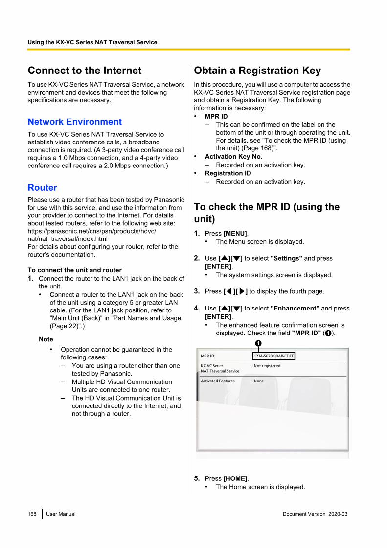
Connect to the InternetTo use KX-VC Series NAT Traversal Service, a networkenvironment and devices that meet the followingspecifications are necessary.
Network EnvironmentTo use KX-VC Series NAT Traversal Service toestablish video conference calls, a broadbandconnection is required. (A 3-party video conference callrequires a 1.0 Mbps connection, and a 4-party videoconference call requires a 2.0 Mbps connection.)
RouterPlease use a router that has been tested by Panasonicfor use with this service, and use the information fromyour provider to connect to the Internet. For detailsabout tested routers, refer to the following web site:https://panasonic.net/cns/psn/products/hdvc/nat/nat_traversal/index.htmlFor details about configuring your router, refer to therouter’s documentation.
To connect the unit and router1. Connect the router to the LAN1 jack on the back of
the unit.• Connect a router to the LAN1 jack on the back
of the unit using a category 5 or greater LANcable. (For the LAN1 jack position, refer to"Main Unit (Back)" in "Part Names and Usage(Page 22)".)
Note• Operation cannot be guaranteed in the
following cases:– You are using a router other than one
tested by Panasonic.– Multiple HD Visual Communication
Units are connected to one router.– The HD Visual Communication Unit is
connected directly to the Internet, andnot through a router.
Obtain a Registration KeyIn this procedure, you will use a computer to access theKX-VC Series NAT Traversal Service registration pageand obtain a Registration Key. The followinginformation is necessary:• MPR ID
– This can be confirmed on the label on thebottom of the unit or through operating the unit.For details, see "To check the MPR ID (usingthe unit) (Page 168)".
• Activation Key No.– Recorded on an activation key.
• Registration ID– Recorded on an activation key.
To check the MPR ID (using theunit)1. Press [MENU].
• The Menu screen is displayed.
2. Use [ ][ ] to select "Settings" and press[ENTER].• The system settings screen is displayed.
3. Press [ ][ ] to display the fourth page.
4. Use [ ][ ] to select "Enhancement" and press[ENTER].• The enhanced feature confirmation screen is
displayed. Check the field "MPR ID" (A).A
5. Press [HOME].• The Home screen is displayed.
168 User Manual Document Version 2020-03
Using the KX-VC Series NAT Traversal Service

To obtain a Registration Key(using a computer)Note
• The following operating systems and webbrowsers are supported:Microsoft Windows 7 operating system– Microsoft Windows Internet Explorer 8/10
web browserMicrosoft Windows 8 operating system– Internet Explorer 10– Mozilla Firefox web browser
1. From a computer, access the KX-VC Series NATTraversal Service registration page(https://www2.tsunagarunet.com/hdcom/main).• The login screen is displayed.
Note• The login screen is displayed in English.
You can change the language from thedrop-down list in the upper right of thescreen.
2. Enter the characters displayed in the image, andthen click "Apply".
• The function selection screen is displayed.
Note• The fields are case sensitive.
3. Click "Apply new" next to HDVC.
• The new application screen is displayed.
4. Fill in the following items:
"MPR ID""Activation Key No.""Registration ID"
5. Click "Next".• The Terms of Use screen is displayed.
6. Read the Terms of Use thoroughly, and if you agreeto the terms, click "Accept".• The Terminal ID selection screen is displayed.
7. Select the Terminal ID you want to use, and thenclick "Next".
Document Version 2020-03 User Manual 169
Using the KX-VC Series NAT Traversal Service

• The information confirmation screen isdisplayed.
Note• Clicking "Click to Show next Terminal
IDs" displays more Terminal IDs availablefor use. You can repeat this operation up to5 times. Once you click "Click to Shownext Terminal IDs", Terminal IDs that havebeen displayed up to that point cannot berecalled.
8. Click "Register".• The value displayed on the screen in
"Registration Key" (16 characters) must beregistered to the unit. Make a printout of thepage or write down the Registration Key on theactivation key or another piece of paper andstore it in a safe place.
IMPORTANT• If you misplace the Registration Key
information, refer to "To display theRegistration Key again (using a computer)(Page 170)".
9. Click "Menu".• The function selection screen is displayed.
To display the Registration Keyagain (using a computer)If you misplace the Registration Key information, youcan display it again by following the procedure below.1. From a computer, access the KX-VC Series NAT
Traversal Service registration page(https://www2.tsunagarunet.com/hdcom/main).• The login screen is displayed.
Note• The login screen is displayed in English.
You can change the language from thedrop-down list in the upper right of thescreen.
2. Enter the characters displayed in the image, andthen click "here" at the bottom of the screen.
• The unit information login screen is displayed.
Note• The fields are case sensitive.
3. Fill in the following items:
"Type": select HDVC"MPR ID"
170 User Manual Document Version 2020-03
Using the KX-VC Series NAT Traversal Service

"Activation Key No.""Registration ID"
4. Click "Next".• The unit information screen is displayed. Check
the "Registration Key" information on thescreen. When you are finished, close thebrowser.
Extending the Service PeriodTo extend the service period, it is necessary topurchase an activation key. The duration of theextension differs according to the card purchased. Fordetails about cards, contact your dealer.
Note• If the service period is extended while the
service period is still in effect, the duration of theextension is added to the current service period.Example: During a 3-month duration serviceperiod, the service period is extended by 1 year.
Jan 1 Mar 1
Service Period: 3 months
Whole day, April 1(Until midnight, April 2)
Whole day, April 2 the following year (Until midnight, April 3)
Extended by: 1 year
Service Period: 1 year and 3 months
Duration: 1 year
• If the service period is extended within 6 monthsfollowing the expiration of a service period, theservice period begins at the time the extensionis performed.
1. From a computer, access the KX-VC Series NATTraversal Service registration page(https://www2.tsunagarunet.com/hdcom/main).• The login screen is displayed.
Note• The login screen is displayed in English.
You can change the language from thedrop-down list in the upper right of thescreen.
Document Version 2020-03 User Manual 171
Using the KX-VC Series NAT Traversal Service

2. Enter the characters displayed in the image, andthen click "Apply".
• The function selection screen is displayed.
Note• The fields are case sensitive.
3. Click "Extension of period" next to HDVC.
• The extension of period screen is displayed.
4. Fill in the following items:
"MPR ID": Input the MPR ID of the unit that youwant to extend the service period for.
"Activation Key No.": Input the Activation Key No.printed on the activation key purchased for theservice period extension."Registration ID": Input the Registration ID printedon the activation key purchased for the serviceperiod extension.
5. Click "Next".• The Terms of Use screen is displayed.
6. Read the Terms of Use thoroughly, and if you agreeto the terms, click "Accept".• The extension confirmation screen is displayed.
7. Click "Register".
• The extension completion screen is displayed.
Note• To register another activation key, click
"Register New" and repeat steps 4 to 7.• The total amount of the service period that
can be registered using activation keys atone time is 6 years, which includes theamount of time remaining in the currentlyactive service period. An activation keycannot be registered if doing so wouldextend the total service period beyond 6years.
• The remaining time in the 3 month trial ofthe activation key included with the productis included in the total time of the serviceperiod. During the trial period, "ActivationKey (NAT Traversal 3 Years)" cannot beadded and registered twice.
8. Click "Menu".• The function selection screen is displayed.
9. Press the unit’s power button to turn it off, and thenon to restart the unit.• The extended service period is reflected on the
unit.
172 User Manual Document Version 2020-03
Using the KX-VC Series NAT Traversal Service

10. Press [MENU].• The Menu screen is displayed.
11. Use [ ][ ] to select "Settings" and press[ENTER].• The system settings screen is displayed.
12. Press [ ] three times.• The fourth page is displayed.
13. Use [ ][ ] to select "Enhancement" and press[ENTER].• The enhanced feature confirmation screen is
displayed. Check the field "KX-VC Series NATTraversal Service", and confirm that theservice period has been extended.
14. Press [HOME].• The Home screen is displayed.
Document Version 2020-03 User Manual 173
Using the KX-VC Series NAT Traversal Service
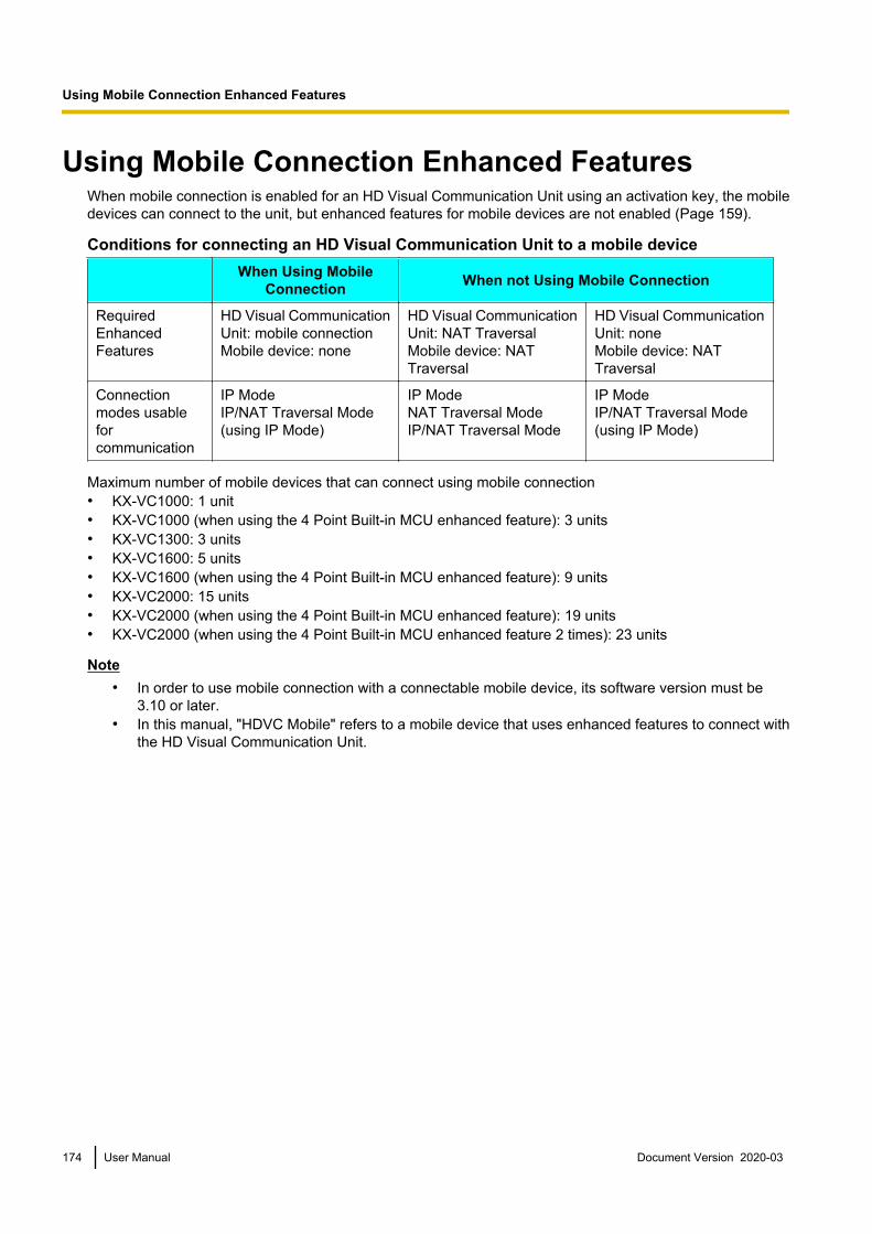
Using Mobile Connection Enhanced FeaturesWhen mobile connection is enabled for an HD Visual Communication Unit using an activation key, the mobiledevices can connect to the unit, but enhanced features for mobile devices are not enabled (Page 159).
Conditions for connecting an HD Visual Communication Unit to a mobile deviceWhen Using Mobile
Connection When not Using Mobile Connection
RequiredEnhancedFeatures
HD Visual CommunicationUnit: mobile connectionMobile device: none
HD Visual CommunicationUnit: NAT TraversalMobile device: NATTraversal
HD Visual CommunicationUnit: noneMobile device: NATTraversal
Connectionmodes usableforcommunication
IP ModeIP/NAT Traversal Mode (using IP Mode)
IP ModeNAT Traversal ModeIP/NAT Traversal Mode
IP ModeIP/NAT Traversal Mode (using IP Mode)
Maximum number of mobile devices that can connect using mobile connection• KX-VC1000: 1 unit• KX-VC1000 (when using the 4 Point Built-in MCU enhanced feature): 3 units• KX-VC1300: 3 units• KX-VC1600: 5 units• KX-VC1600 (when using the 4 Point Built-in MCU enhanced feature): 9 units• KX-VC2000: 15 units• KX-VC2000 (when using the 4 Point Built-in MCU enhanced feature): 19 units• KX-VC2000 (when using the 4 Point Built-in MCU enhanced feature 2 times): 23 units
Note• In order to use mobile connection with a connectable mobile device, its software version must be
3.10 or later.• In this manual, "HDVC Mobile" refers to a mobile device that uses enhanced features to connect with
the HD Visual Communication Unit.
174 User Manual Document Version 2020-03
U
s
i
n
g
M
o
b
i
l
e
C
o
n
n
e
c
t
i
o
n
E
n
h
a
n
c
e
d
F
e
a
t
u
r
e
s
Using Mobile Connection Enhanced Features
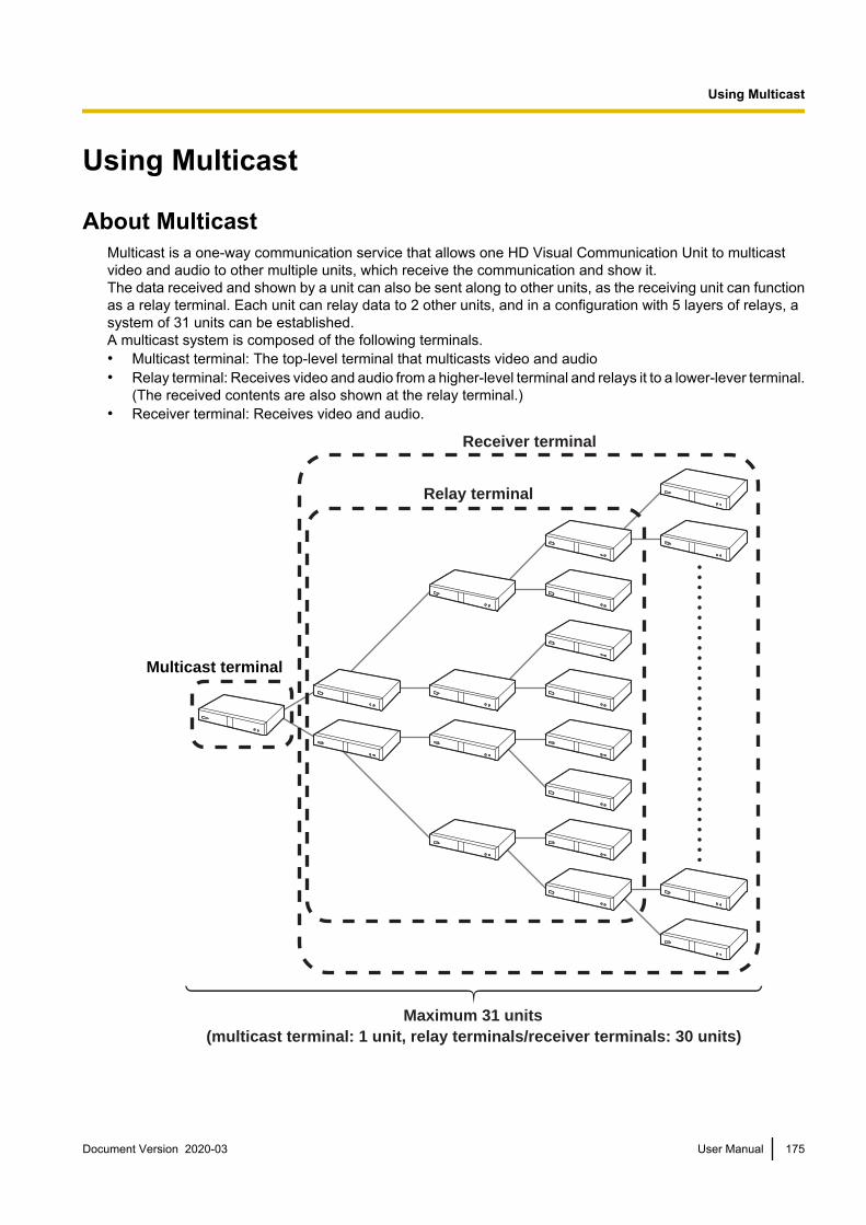
Using Multicast
About MulticastMulticast is a one-way communication service that allows one HD Visual Communication Unit to multicastvideo and audio to other multiple units, which receive the communication and show it.The data received and shown by a unit can also be sent along to other units, as the receiving unit can functionas a relay terminal. Each unit can relay data to 2 other units, and in a configuration with 5 layers of relays, asystem of 31 units can be established.A multicast system is composed of the following terminals.• Multicast terminal: The top-level terminal that multicasts video and audio• Relay terminal: Receives video and audio from a higher-level terminal and relays it to a lower-lever terminal.
(The received contents are also shown at the relay terminal.)• Receiver terminal: Receives video and audio.
Receiver terminal
Relay terminal
Multicast terminal
Maximum 31 units(multicast terminal: 1 unit, relay terminals/receiver terminals: 30 units)
Document Version 2020-03 User Manual 175
U
s
i
n
g
M
u
l
t
i
c
a
s
t
Using Multicast

The multicast feature, compared to usage of an MCU, can reduce the network bandwidth used at the multicastterminal’s sites. When a transmission failure occurs during the multicast, the configuration of the terminals willautomatically change, so it is necessary that all terminals can connect and communicate with each other overthe network.
Note• In order to use the multicast feature, all HD Visual Communication Units that will comprise the multicast
system must have a Multicast activation key (KX-VCS302) installed.• The multicast feature will not operate when using IPv6 addresses.• To enable "Multicast" in "Enhancement", be sure to assign an IPv4 address to the unit in "Network
Settings". In cases where an IPv4 address is not assigned, such as when "IP Address (LAN1)" (setting) is set to "Auto", but the status "Address is not assigned" is displayed, communicationusing an IPv6 address cannot occur.
• The multicast feature will not operate when using IP Mode (H.323).• The multicast feature will not operate when using NAT Traversal Mode.• The multicast data cannot be encrypted.• Connection using a SIP server cannot be performed.• When configuring a system of 32 or more units, a multicast server is required. For details, contact your
dealer.
Multicast Operation
Starting MulticastIn order to perform multicasting, multicast tree settings must first be set (Page 177, Page 178). When themulticast is started from the multicast tree setting screen, connections are established with the lower levelterminals and then the multicast will begin (Page 182).If a lower-level terminal’s power is not on, or there is a network failure, and there is no response for theconnection confirmation, the configuration of the multicast tree will automatically change, and then the multicastwill begin. If a terminal that was removed from the configuration at startup responds with a connectionconfirmation during the multicast, the multicast tree will automatically re-add the terminal and multicast datato it.
Ending the MulticastPress [END] at the multicast terminal to end the multicast.
Handling of Trouble During a MulticastIf a relay terminal loses its ability to connect to the multicast due to problems such as network trouble, themulticast tree will automatically adjust and continue the multicast.
176 User Manual Document Version 2020-03
Using Multicast

The Multicast TreeSet the multicast tree to perform the multicast. The multicast tree defines the positions of terminals within themulticast system. The position of terminals within the multicast tree are displayed using node IDs, and theirpositional relationships are as follows.
0 1 3 7 1523
11 1927
5 9 1725
13 21
2 4 8
12
6 10
14
291624202818262230
Receiver terminalMulticast terminal
About the NetworkThe multicast terminal and relay terminals multicast data to up to 2 terminals, so all terminals in the multicastsystem must have bandwidth twice that of the multicast maximum bandwidth (1, 1.2, 2, 3, 4, 5 Mbps). Therecommended resolutions for the multicast maximum bandwidth are as follows.
Maximum bandwidthMaximum resolution
Full HD(1080/30p)
HD(720/60p)
5 Mbps recommended
4 Mbps recommended
3 Mbps recommended
2 Mbps recommended recommended
1.2 Mbps recommended
1 Mbps recommended
Document Version 2020-03 User Manual 177
Using Multicast

Note• During the multicast, if the connection bandwidth drops, the sending bandwidth will drop as well,
lowering the resolution and/or the frame rate.• The quality of the multicast video and audio is affected by packet round trip time (RTT), the packet loss
ratio, and the number of packets re-sent. Terminals store approximately 1 second of data for resending,but if sending/receiving is delayed beyond this, the image may become corrupted. For details onnetwork design that takes into account issues such as round trip time and the packet loss ratio, contactyour dealer.
Setting the System
Setting Multicast1. In step 3 of "Changing System Settings/Performing System Maintenance (Page 117)", select "Multicast
Setting" and press [ENTER].• The multicast setting screen is displayed.
2. Use [ ][ ] to select the following items for input."Audio Input": Press [ENTER] and use [ ][ ] to select the microphone of the multicast terminal to usefor the multicast feature.– "MIC·Audio In" (default): Audio is input from both the Boundary Microphone and the RCA inputs.– "Audio In": Audio is input from the RCA inputs."Min. bandwidth of Video trans.": Enter the minimum bandwidth (0 kbps, 64 kbps to 1500 kbps) duringcalls when bandwidth control is used. (Default: 0 kbps)
Note• Enter 0 to disable minimum bandwidth.
3. Press [G].• A dialogue box to confirm the saving of settings is displayed.
4. Use [ ][ ] to select "Yes" and press [ENTER].• The system settings screen is displayed.
Note• "Multicast Setting" can be configured when "Multicast" in "Enhancement" is enabled.
Making Administrator Menu Settings
Registering the Multicast TreeSets the terminals and multicast conditions registered for the multicast tree. Up to 10 multicast trees can beregistered.
Note• "Multicast Tree Set." is available when "Multicast" is enabled for "Enhancement".
178 User Manual Document Version 2020-03
Using Multicast

New Registration1. Perform steps 1 to 6 of "Administrator Menu List (Page 140)", and then from Administrator Menu List, select
"Multicast Tree Set." and press [ENTER].• The multicast tree screen is displayed.
2. Use [ ][ ] to select ""Not Registered"".3. Press [B].
• The multicast tree setting screen is displayed.
4. Use [ ][ ] to select the following items for input:"Multicast Name": Enter the multicast tree name (maximum 24 characters) (Page 196)."Max. Bandwidth": Press [ENTER] and use [ ][ ] to select the maximum bandwidth to be used for themulticast (1.0, 1.2, 2.0, 3.0, 4.0, 5.0 Mbps) (default: 5.0 Mbps).
Note• All terminals registered to the multicast tree must have twice the available bandwidth as set in
"Max. Bandwidth".• In "Call set up", the values for "Max. Bandwidth", "Max. Bandwidth Per Site", "Max.
Bandwidth Per Site (LAN 1)", and "Max. Bandwidth Per Site (LAN 2)" have no effect on themaximum bandwidth used for multicasting.
"Max. Resolution": Press [ENTER] and use [ ][ ] to select "Full HD" (default) or "HD".
Note• When the bandwidth of the connection used during the multicast drops, the resolution and/or frame
rate of the multicast data may lower.
"Multicast Default Video": Press [ENTER] and use [ ][ ] to select the video to send when the multicaststarts.– "Main Camera" (default): The video of the main camera is sent.– "Sub Camera": The video of the sub camera is sent.– "PC": The image of the computer is sent.
Note• Performing contents sharing operations can change the video being sent during a multicast
(Page 90).
"Multicast Def. Noise reduction": Use [ ][ ] to select whether noise reduction is enabled when themulticast starts.– "ON" (default): Noise reduction is enabled.– "OFF": Noise reduction is disabled.
Document Version 2020-03 User Manual 179
Using Multicast

Note• "Multicast Def. Noise reduction" is not displayed for the KX-VC1000.
"MIC detection": Use [ ][ ] to select the microphone status display.– "ON": Displays the microphone status.– "OFF" (default): Hides the microphone status.
"IP Address": Input the IP address of the multicast terminal at the top of the multicast tree.
Note• If the value for "IP Address" contains 1 or 2 digit numbers, enter these numbers as they are. Do
not enter values such as ".001".Example: The IP address is [192.168.0.1].Correct entry: [192.168.0.1]Wrong entry: [192.168.000.001]
5. Press [G].• A dialogue box to confirm the saving of settings is displayed.
6. Use [ ][ ] to select "Yes" and press [ENTER].• The multicast tree screen is displayed.
7. Use [ ][ ] to select the newly registered multicast tree and press [B].• The multicast tree setting screen is displayed.
8. Use [ ][ ] to select "Target" and press [ENTER].• The multicast target screen is displayed.
Note• If no multicast targets with a " " mark displayed are registered in the selection column, the multicast
will not begin when [START] is pressed.• When "LAN 2" is set to "OFF" (Page 122), or when using a KX-VC1000 or KX-VC1300, the LAN
column is not displayed.• If [ ] is displayed in a target's LAN column, multicasting will not start when you press [START].
The IP address specified for "IP Address" (Page 180) is an IP address of a network that the targetcannot communicate with. Confirm the target's IP address.
9. Use [ ][ ] to select the ""Not Registered"" target with the lowest node ID, and then press [B].• A dialogue box is displayed for selecting the input method.
180 User Manual Document Version 2020-03
Using Multicast

When "Input Address" is selected• The address input screen is displayed.
Use [ ][ ] to select the following items for input:"Multicast Target Name": Input the multicast target name (maximum 24 characters) (Page 196)."IP Address": Enter the IP address.Press [G].• The multicast target screen is displayed.
Note• Only IPv4 addresses can be used for the multicast feature.
When "Contact list" is selected• The contact list screen is displayed.
Use [ ][ ] to select the other party to register and press [ENTER].• The multicast target screen is displayed.
Note• To continue registering multicast targets, repeat the procedure from step 9.• Register multicast targets starting from the lowest available node ID. The node ID of a ""Not
Registered"" target cannot be selected for registration if it is not the lowest available number.10. Press [G].
• A dialogue box to confirm the saving of settings is displayed.11. Use [ ][ ] to select "Yes" and press [ENTER].
• The multicast tree screen is displayed.
Note• To continue registering multicast trees, repeat steps 2–11 of the procedure.
Editing Registered Contents1. In step 7 of "Administrator Menu List (Page 140)", select "Multicast Tree Set." and press [ENTER].
• The multicast tree screen is displayed.2. Use [ ][ ] to select the multicast tree to edit.
Document Version 2020-03 User Manual 181
Using Multicast
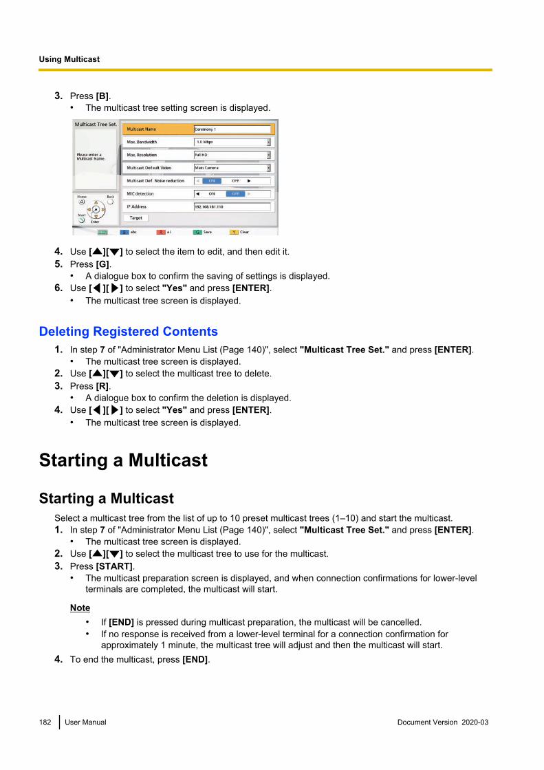
3. Press [B].• The multicast tree setting screen is displayed.
4. Use [ ][ ] to select the item to edit, and then edit it.5. Press [G].
• A dialogue box to confirm the saving of settings is displayed.6. Use [ ][ ] to select "Yes" and press [ENTER].
• The multicast tree screen is displayed.
Deleting Registered Contents1. In step 7 of "Administrator Menu List (Page 140)", select "Multicast Tree Set." and press [ENTER].
• The multicast tree screen is displayed.2. Use [ ][ ] to select the multicast tree to delete.3. Press [R].
• A dialogue box to confirm the deletion is displayed.4. Use [ ][ ] to select "Yes" and press [ENTER].
• The multicast tree screen is displayed.
Starting a Multicast
Starting a MulticastSelect a multicast tree from the list of up to 10 preset multicast trees (1–10) and start the multicast.1. In step 7 of "Administrator Menu List (Page 140)", select "Multicast Tree Set." and press [ENTER].
• The multicast tree screen is displayed.2. Use [ ][ ] to select the multicast tree to use for the multicast.3. Press [START].
• The multicast preparation screen is displayed, and when connection confirmations for lower-levelterminals are completed, the multicast will start.
Note• If [END] is pressed during multicast preparation, the multicast will be cancelled.• If no response is received from a lower-level terminal for a connection confirmation for
approximately 1 minute, the multicast tree will adjust and then the multicast will start.4. To end the multicast, press [END].
182 User Manual Document Version 2020-03
Using Multicast

Starting a Multicast by Selecting the Multicast TargetSelect a multicast target from the multicast target list registered in advance to the multicast tree, and start themulticast.1. In step 7 of "Administrator Menu List (Page 140)", select "Multicast Tree Set." and press [ENTER].
• The multicast tree screen is displayed.2. Use [ ][ ] to select the multicast tree to use for the multicast, and press [B].
• The multicast tree setting screen is displayed.
3. Use [ ][ ] to select "Target" and press [ENTER].• The multicast target screen is displayed.
4. Use [ ][ ] to select a multicast target and press [ENTER].• The " " mark in the selection column will be added or removed. The multicast will start for the multicast
targets displaying a " " mark.
Note• If no multicast targets with a " " mark displayed are registered in the selection column, the multicast
will not begin when [START] is pressed.• If [ ] is displayed in a target's LAN column, multicasting will not start when you press [START].
The IP address specified for "IP Address" (Page 180) is an IP address of a network that the targetcannot communicate with. Confirm the target's IP address.
Document Version 2020-03 User Manual 183
Using Multicast

5. Press [START].• The multicast preparation screen is displayed, and when connection confirmations for lower-level
terminals are completed, the multicast will start.
Note• If [END] is pressed during multicast preparation, the multicast will be cancelled.• If no response is received from a lower-level terminal for a connection confirmation for
approximately 1 minute, the multicast tree will adjust and then the multicast will start.6. To end the multicast, press [END].
184 User Manual Document Version 2020-03
Using Multicast

Confirming the Transmission Status During a Multicast (MulticastTerminal)
1 Press [STATUS].• The multicast information screen is displayed.
2
1
2 Use [ ][ ] to select a multicast target and press[ENTER].• The communication status of the selected multicast
target is displayed.
Note• When [G] is pressed, the displayed party changes.• When automatic adjustment for the multicast tree occurs, the adjusted node IDs are displayed in
"Current" of "Node ID (Set / Current)".
Document Version 2020-03 User Manual 185
Using Multicast

Confirming the Transmission Status During a Multicast (RelayTerminal/Receiver Terminal)
1 Press [STATUS].• The multicast information screen is displayed.
1
Starting and Stopping Recording During a Multicast1. Press [MENU].
• The multicast menu is displayed.2. Select "USB Rec" and press [ENTER].
When not recording: A dialogue box to confirm starting recording is displayed. Use [ ][ ] to select"Yes" or "No" and press [ENTER].– Selecting "Yes" starts recording.– Selecting "No" does not start recording.When recording: A dialogue box to confirm stopping recording is displayed. Use [ ][ ] to select"Yes" or "No" and press [ENTER].– Selecting "Yes" stops recording.– Selecting "No" does not stop recording.
186 User Manual Document Version 2020-03
Using Multicast

Using USB Recording Features• Record video and audio during a call, multicast, or while idle on a USB memory device connected to the
back of the unit.• You can continue recording a different transmission status. For example, you can start recording while idle,
and then start and end a call while recording.• To use USB recording features, set "USB Rec" to "ON" in "Security Settings" (Page 151). Also configure
recording related settings in "Making Recording Settings (Page 134)".
Note• If the multicast terminal is KX-VC300, KX-VC500 or KX-VC600, you cannot record with relay and
receiver terminals.
About USB Memory• A mass storage class (FAT16 or FAT32 format) compatible USB memory device can be used with this
unit.• The following types of USB memory devices cannot be used:
– U3 smart drives (USB memory devices compatible with the U3 platform)– USB memory devices with security features– USB memory devices formatted using NTFS– USB memory devices with multiple LUNs (Logical Unit Numbers)– USB memory devices formatted with multiple partitions
About USB Memory Devices and Recording Operations• If a USB memory device is not connected when recording starts, a dialogue box to confirm a USB memory
device connection is displayed. Press [ENTER], connect a USB memory device, and start recording again.A similar dialogue box is also displayed when the USB memory device cannot be recognized. Replace itwith another USB memory device and start recording again.
• If there is insufficient free space in the USB memory device when recording starts, a dialogue box notifyingthat recording cannot start is displayed. Press [ENTER], replace the USB memory device with anotherone, and start recording again.
• If the amount of free space in the USB memory device becomes low while recording, a dialogue box toselect whether to continue or stop recording is displayed.Use [ ][ ] to select "Yes" or "No" and press [ENTER].– Selecting "Yes" stops recording.– Selecting "No" continues recording.When there is no free space, recording is stopped automatically and a dialogue box notifying recordinghas been stopped is displayed.Press [ENTER], replace the USB memory device with another one, and start recording again.
• If the USB memory device is removed while recording, a dialogue box is displayed and recording is stopped.However, recordings up to 5 minutes before removal are not saved. Also, files may get corrupted and maynot be able to play back properly. Do not remove the USB memory device while recording.
• If the AC power turns off while recording, files in the USB memory device may get corrupted and may notbe able to play back properly. Do not turn off the AC power while recording.
About Recorded Data• When recording starts, a file named "vc_DATE_TIME.mp4" is created in the root directory.
Example) When recording starts on December 1, 2017, 13:30:30: vc_20171201_133030.mp4• If the continuous recording time exceeds 4 hours (2 hours in high-quality mode), the subsequent recording
is automatically saved in a new file. The name of the new file contains the date and time when the recordingfile was switched.
• The following are the main specifications.
Document Version 2020-03 User Manual 187
U
s
i
n
g
U
S
B
R
e
c
o
r
d
i
n
g
F
e
a
t
u
r
e
s
Using USB Recording Features
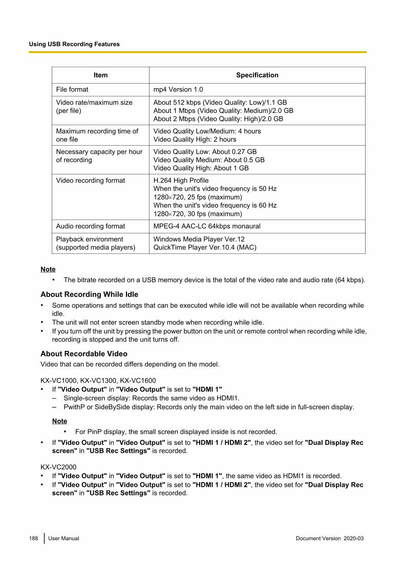
Item Specification
File format mp4 Version 1.0
Video rate/maximum size(per file)
About 512 kbps (Video Quality: Low)/1.1 GBAbout 1 Mbps (Video Quality: Medium)/2.0 GBAbout 2 Mbps (Video Quality: High)/2.0 GB
Maximum recording time ofone file
Video Quality Low/Medium: 4 hoursVideo Quality High: 2 hours
Necessary capacity per hourof recording
Video Quality Low: About 0.27 GBVideo Quality Medium: About 0.5 GBVideo Quality High: About 1 GB
Video recording format H.264 High ProfileWhen the unit's video frequency is 50 Hz1280´720, 25 fps (maximum)When the unit's video frequency is 60 Hz1280´720, 30 fps (maximum)
Audio recording format MPEG-4 AAC-LC 64kbps monaural
Playback environment(supported media players)
Windows Media Player Ver.12QuickTime Player Ver.10.4 (MAC)
Note• The bitrate recorded on a USB memory device is the total of the video rate and audio rate (64 kbps).
About Recording While Idle• Some operations and settings that can be executed while idle will not be available when recording while
idle.• The unit will not enter screen standby mode when recording while idle.• If you turn off the unit by pressing the power button on the unit or remote control when recording while idle,
recording is stopped and the unit turns off.
About Recordable VideoVideo that can be recorded differs depending on the model.
KX-VC1000, KX-VC1300, KX-VC1600• If "Video Output" in "Video Output" is set to "HDMI 1"
– Single-screen display: Records the same video as HDMI1.– PwithP or SideBySide display: Records only the main video on the left side in full-screen display.
Note• For PinP display, the small screen displayed inside is not recorded.
• If "Video Output" in "Video Output" is set to "HDMI 1 / HDMI 2", the video set for "Dual Display Recscreen" in "USB Rec Settings" is recorded.
KX-VC2000• If "Video Output" in "Video Output" is set to "HDMI 1", the same video as HDMI1 is recorded.• If "Video Output" in "Video Output" is set to "HDMI 1 / HDMI 2", the video set for "Dual Display Rec
screen" in "USB Rec Settings" is recorded.
188 User Manual Document Version 2020-03
Using USB Recording Features

About Recordable Audio• While idle
Records the audio of its own site.• During a call
– Main site: Records the audio of the loudest four sites and its own site. If its own site is included in theloudest four sites, the audio of the four sites is recorded.
– Sub site: Records the audio of its own site and the main site (including the audio of other sub sitescombined by the main site).
• During a multicastRecords only the audio of the multicast terminal.
Document Version 2020-03 User Manual 189
Using USB Recording Features
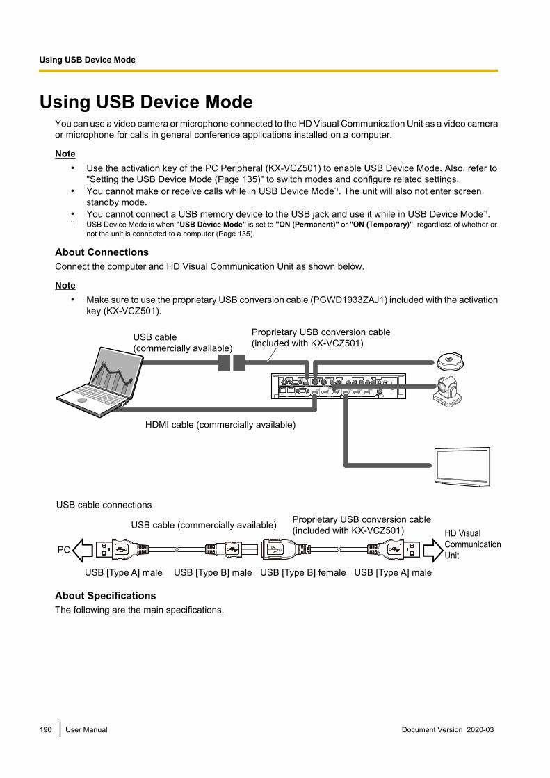
Using USB Device ModeYou can use a video camera or microphone connected to the HD Visual Communication Unit as a video cameraor microphone for calls in general conference applications installed on a computer.
Note• Use the activation key of the PC Peripheral (KX-VCZ501) to enable USB Device Mode. Also, refer to
"Setting the USB Device Mode (Page 135)" to switch modes and configure related settings.• You cannot make or receive calls while in USB Device Mode*1. The unit will also not enter screen
standby mode.• You cannot connect a USB memory device to the USB jack and use it while in USB Device Mode*1.*1 USB Device Mode is when "USB Device Mode" is set to "ON (Permanent)" or "ON (Temporary)", regardless of whether or
not the unit is connected to a computer (Page 135).
About ConnectionsConnect the computer and HD Visual Communication Unit as shown below.
Note• Make sure to use the proprietary USB conversion cable (PGWD1933ZAJ1) included with the activation
key (KX-VCZ501).
USB cable
(commercially available)
Proprietary USB conversion cable
(included with KX-VCZ501)
HDMI cable (commercially available)
USB cable connections
USB cable (commercially available)Proprietary USB conversion cable
(included with KX-VCZ501)
PC
USB [Type A] male USB [Type A] maleUSB [Type B] male USB [Type B] female
HD Visual
Communication
Unit
About SpecificationsThe following are the main specifications.
190 User Manual Document Version 2020-03
U
s
i
n
g
U
S
B
D
e
v
i
c
e
M
o
d
e
Using USB Device Mode

Item Specification
Video Standard UVC Version 1.0
Video format Motion JPEG
Resolution When the unit's video frequency is 50 Hz640 ´ 480 (maximum 25 fps)1280 ´ 720 (maximum 12.5 fps)When the unit's video frequency is 60 Hz640 ´ 480 (maximum 30 fps)1280 ´ 720 (maximum 15 fps)
Audio Standard UAC Version 1.0
Audio format PCM, 16bits, 32kbps
Supported OS Microsoft Windows 7 SP2Microsoft Windows 8.1 operating systemMicrosoft Windows 10 operating system
Note• If the computer goes into sleep, is locked, or goes into hibernate while using USB Device Mode, the
video camera/microphone of the HD Visual Communication Unit may not be able to be used with thecomputer. In this case, perform one of the following operations.– Disconnect and then reconnect the USB cable– Set "USB Device Mode" to "OFF" and then set it again to "ON (Permanent)" or "ON
(Temporary)" (Page 135)• If the USB cable is disconnected and the reconnected while general conference applications installed
on a computer are operating, the video camera/microphone of the HD Visual Communication Unit maynot be able to be used with the computer. In this case, perform one or both of the following operations.– Restart the general conference applications– Set "USB Device Mode" to "OFF" and then set it again to "ON (Permanent)" or "ON
(Temporary)" (Page 135)
Document Version 2020-03 User Manual 191
Using USB Device Mode

Using Web Hybrid ModeInterconnects HD Visual Communication Unit video conferences and web conferences using generalconference applications installed on a computer. It shares the audio of the video conferences and the webconferences and allows the audio of one of the conferences to be constantly heard in both conferences. Also,by sharing the contents of the computer screen, video camera images from the web conference can be sharedwith video conference call participants.
Note• Use the activation key of the Web hybrid mode expansion (KX-VCZ502) to enable the Web Hybrid
Mode feature. Also, refer to "Setting the Web Hybrid Mode (Page 136)" to switch modes and configurerelated settings.
• The unit will not enter screen standby mode while in Web Hybrid Mode*1. Also, you cannot connect aUSB memory device to the USB jack and use it.
*1 Web Hybrid Mode is when "Web Hybrid Mode" is set to "ON (Permanent)" or "ON (Temporary)", regardless of whether ornot the unit is connected to a computer (Page 136).
About ConnectionsConnect the computer and HD Visual Communication Unit as shown below.
Note• Make sure to use the proprietary USB conversion cable (PGWD1933ZAJ1) included with the activation
key (KX-VCZ502).• Check that a Panasonic device is selected in the audio input/output settings of the general conference
applications.
Proprietary USB conversion cable
(included with KX-VCZ502)
HDMI cable (commercially available)
USB cable
(commercially available)
USB cable connections
USB cable (commercially available)Proprietary USB conversion cable
(included with KX-VCZ502)
PC
USB [Type A] male USB [Type A] maleUSB [Type B] male USB [Type B] female
HD Visual
Communication
Unit
About SpecificationsThe following are the main specifications.
192 User Manual Document Version 2020-03
U
s
i
n
g
W
e
b
H
y
b
r
i
d
M
o
d
e
Using Web Hybrid Mode

Item Specification
Audio Standard UAC Version 1.0
Audio format PCM, 16bits, 32kbps
Supported OS Microsoft Windows 7 SP2Microsoft Windows 8.1Microsoft Windows 10
Note• Set the computer’s multiple display setting to "Duplicate these displays". (Multiple display settings are
enabled when the computer is connected to with Web Hybrid Mode.) When the web conference screenis displayed on the TV at your own site that was set for "Extend these displays" and the video conferenceof the other party shares contents, the web conference screen will not be able to be checked.
• Operations are as follows during Web Hybrid Mode.– Regardless of "MIC Setting", all Digital Boundary Microphones collect sound using "Center
Mono" (Page 131).– Even if "Main Camera Audio input" is set to "ON", audio input will be from PC-HDMI, not from
the main camera (Page 154).– If "Output of HDMI 3" is set to a setting other than "Local site video", the following audio is split
between L and R and outputted to HDMI3 (Page 153).L: mixes your own site’s audio, other sites’ audio, and PC-HDMI audioR: mixes your own site’s audio and other sites’ audio
– The audio input is the same as when "HDMI Audio input / content" (Page 154) is set to "PC".
Document Version 2020-03 User Manual 193
Using Web Hybrid Mode

Changing the Remote Control BatteriesFor users in Taiwan only
1. Open the cover.
2. Take out the R6 (AA) batteries.3. Insert new batteries (R6 [AA] dry cell), minus side first, then close the cover.
194 User Manual Document Version 2020-03
M
i
s
c
e
l
l
a
n
e
o
u
s
Miscellaneous

Cleaning the UnitWhen cleaning the unit, make sure the power is off and all cables are unplugged. Cleaning the unit while thepower is on may cause electric shock.
• Wipe the unit with a dry, soft cloth.When the unit is very dirty, first clean it with a neutral, household cleaning agent using a well-wrung, dampcloth. Then, wipe down the unit with a dry, soft cloth.
• Do not use the following when cleaning the unit. They may cause unit discolouration or damage.– Petroleum– Scouring powder– Alcohol– Thinner– Benzine– Wax– Hot water– Powder soap
• If using a chemically treated cleaning cloth, be sure to follow all accompanying directions and warnings.
Document Version 2020-03 User Manual 195
Miscellaneous

Inputting Letters and NumbersYou can use the remote control to input letters and numbers.The following tables detail the characters and numbers that can be input. The language that can be inputdepends on which language is selected through system settings.
Press the indicated button repeatedly to cycle through the characters and numbers assigned to that buttonuntil the character you want to input is displayed. If you want to input another character using the same button,press [ ] to move the input cursor to the right.
196 User Manual Document Version 2020-03
I
n
p
u
t
Input

Table 1 English/Arabic
Button
Latin Mode
Uppercase-preferred
Mode
Uppercase-preferred
Mode
Lowercase-preferred
Mode
Uppercase-preferred
Mode
Lowercase-preferred
Mode
Lowercase-preferred
Mode
Extended Character 1(Western Europe) Mode
Extended Character 2(Eastern Europe) ModeNumber
Mode
1 1 1 1 1 1
A B C a b c 2
A À Á Â Ã Ä Å Æ B C Ç a à á â ã ä å æ b c ç 2
a à á â ã ä å æ b c ç A À Á Â Ã Ä Å Æ B C Ç 2
2
D E F d e f 3 3
G H I g h i 4 4
J K L j k l 5 5
M N O m n o 6 6
P Q R S p q r s 7 7
T U V t u v 8 8
W X Y Z w x y z 9
9
0 Space 0
. @ : ; " = + < >
. @ : ; " = + < >
# _ - & $ \ % ~ ! ? / ( ) , [ ] { | } '
1
a b c A B C 2
d e f D E F 3
g h i G H I 4
j k l J K L 5 J K L j k l 5 j k l J K L 5
m n o M N O 6
p q r s P Q R S 7
t u v T U V 8
w x y z W X Y Z 9
0 Space 0 Space 0 Space 0 Space 0 Space
. @ : ; " = + < >
. @ : ; " = + < >
. @ : ; " = + < >
. @ : ; " = + < >
. @ : ; " = + < >
# _ - & $ \ % ~ ! ? / ( ) , [ ] { | } '
# _ - & $ \ % ~ ^ ! ? / ` ( ) , [ ] { | } '
# _ - & $ \ % ~ ! ? / ( ) , [ ] { | } '
# _ - & $ \ % ~ ! ? / ( ) , [ ] { | } '
# _ - & $ \ % ~ ^ ! ? / ` ( ) , [ ] { | } '
# _ - & $ \ % ~ ^ ! ? / ` ( ) , [ ] { | } '
D E È É Ê Ë F d e è é ê ë f 3
d e è é ê ë f D E È É Ê Ë F 3
G H I Í g h i í 4 g h i í G H I Í 4
M N Ñ O Ò Ó Ô Õ Ö Ø Œ m n ñ o ò ó ô õ ö ø œ 6
m n ñ o ò ó ô õ ö ø œ M N Ñ O Ò Ó Ô Õ Ö Ø Œ 6
Document Version 2020-03 User Manual 197
Input
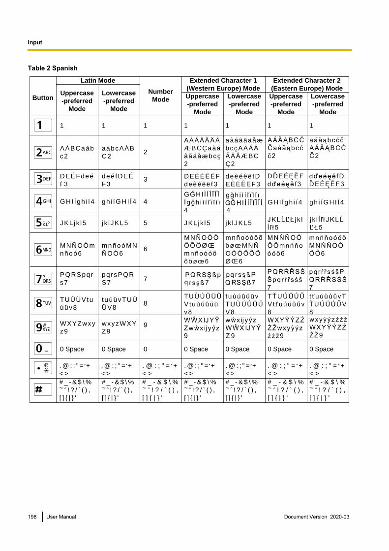
Table 2 Spanish
Button
Latin Mode
Uppercase-preferred
Mode
Uppercase-preferred
Mode
Lowercase-preferred
Mode
Uppercase-preferred
Mode
Lowercase-preferred
Mode
Lowercase-preferred
Mode
Extended Character 1(Western Europe) Mode
Extended Character 2(Eastern Europe) ModeNumber
Mode
1 1 1 1 1 1
A Á B C a á b c 2
A À Á Â Ã Ä Å Æ B C Ç a à á â ã ä å æ b c ç 2
a à á â ã ä å æ b c ç A À Á Â Ã Ä Å Æ B C Ç 2
2
D E É F d e é f 3
3
G H I Í g h i í 4 4
J K L j k l 5 5
M N Ñ O Ó m n ñ o ó 6
6
P Q R S p q r s 7 7
T U Ú Ü V t u ú ü v 8 8
W X Y Z w x y z 9
9
0 Space 0
. @ : ; " = + < >
. @ : ; " = + < >
# _ - & $ \ % ~ ! ? / ( ) , [ ] { | } '
1
a á b c A Á B C 2
d e é f D E É F 3
g h i í G H I Í 4
j k l J K L 5 J K L j k l 5 j k l J K L 5
m n ñ o ó M N Ñ O Ó 6
p q r s P Q R S 7
t u ú ü v T U Ú Ü V 8
w x y z W X Y Z 9
0 Space 0 Space 0 Space 0 Space 0 Space
. @ : ; " = + < >
. @ : ; " = + < >
. @ : ; " = + < >
. @ : ; " = + < >
. @ : ; " = + < >
# _ - & $ \ % ~ ! ? / ( ) , [ ] { | } '
# _ - & $ \ % ~ ^ ! ? / ` ( ) , [ ] { | } '
# _ - & $ \ % ~ ! ? / ( ) , [ ] { | } '
# _ - & $ \ % ~ ! ? / ( ) , [ ] { | } '
# _ - & $ \ % ~ ^ ! ? / ` ( ) , [ ] { | } '
# _ - & $ \ % ~ ^ ! ? / ` ( ) , [ ] { | } '
D E È É Ê Ë F d e è é ê ë f 3
d e è é ê ë f D E È É Ê Ë F 3
G H I Í g h i í 4 g h i í G H I Í 4
M N Ñ O Ò Ó Ô Õ Ö Ø Œ m n ñ o ò ó ô õ ö ø œ 6
m n ñ o ò ó ô õ ö ø œ M N Ñ O Ò Ó Ô Õ Ö Ø Œ 6
198 User Manual Document Version 2020-03
Input

Table 3 Portuguese
Button
Latin Mode
Uppercase-preferred
Mode
Uppercase-preferred
Mode
Lowercase-preferred
Mode
Uppercase-preferred
Mode
Lowercase-preferred
Mode
Lowercase-preferred
Mode
Extended Character 1(Western Europe) Mode
Extended Character 2(Eastern Europe) ModeNumber
Mode
1 1 1 1 1 1
A Á Â Ã À B C Ç a á â ã à b c ç 2
A À Á Â Ã Ä Å Æ B C Ç a à á â ã ä å æ b c ç 2
a à á â ã ä å æ b c ç A À Á Â Ã Ä Å Æ B C Ç 2
2
D E É Ê F d e é ê f 3
3
G H I Í g h i í 4 4
J K L j k l 5 5
M N O Ó Ô Õ m n o ó ô õ 6
6
P Q R S p q r s 7 7
T U Ú Ü V t u ú ü v 8 8
W X Y Z w x y z 9
9
0 Space 0
. @ : ; " = + < >
. @ : ; " = + < >
# _ - & $ \ % ~ ! ? / ( ) , [ ] { | } '
1
a á â ã à b c ç A Á Â Ã À B C Ç 2
d e é ê f D E É Ê F 3
g h i í G H I Í 4
j k l J K L 5 J K L j k l 5 j k l J K L 5
m n o ó ô õ M N O Ó Ô Õ 6
p q r s P Q R S 7
t u ú ü v T U Ú Ü V 8
w x y z W X Y Z 9
0 Space 0 Space 0 Space 0 Space 0 Space
. @ : ; " = + < >
. @ : ; " = + < >
. @ : ; " = + < >
. @ : ; " = + < >
. @ : ; " = + < >
# _ - & $ \ % ~ ! ? / ( ) , [ ] { | } '
# _ - & $ \ % ~ ^ ! ? / ` ( ) , [ ] { | } '
# _ - & $ \ % ~ ! ? / ( ) , [ ] { | } '
# _ - & $ \ % ~ ! ? / ( ) , [ ] { | } '
# _ - & $ \ % ~ ^ ! ? / ` ( ) , [ ] { | } '
# _ - & $ \ % ~ ^ ! ? / ` ( ) , [ ] { | } '
D E È É Ê Ë F d e è é ê ë f 3
d e è é ê ë f D E È É Ê Ë F 3
G H I Í g h i í 4 g h i í G H I Í 4
M N Ñ O Ò Ó Ô Õ Ö Ø Œ m n ñ o ò ó ô õ ö ø œ 6
m n ñ o ò ó ô õ ö ø œ M N Ñ O Ò Ó Ô Õ Ö Ø Œ 6
Document Version 2020-03 User Manual 199
Input

Table 4 Japanese
1
A B C a b c 2
D E F d e f 3
G H I g h i 4
J K L j k l 5
M N O m n o 6
P Q R S p q r s 7
T U V t u v 8
W X Y Z w x y z 9
0 (Normal space)
. @ : ; " = + < >
# _ - & $ \ % ~ ! ? / ( ) , [ ] { | } '
1
a b c A B C 2
d e f D E F 3
g h i G H I 4
j k l J K L 5
m n o M N O 6
p q r s P Q R S 7
t u v T U V 8
w x y z W X Y Z 9
0 (Normal space)
. @ : ; " = + < >
# _ - & $ \ % ~ ! ? / ( ) , [ ] { | } '
Button Katakana Mode(Full-Width)
Uppercase-preferred Mode
Lowercase-preferred Mode
Number Mode(Normal)
アイウエオァィゥェォ
カキクケコ
サシスセソ
タチツテトッ
ナニヌネノ
ハヒフヘホ
マミムメモ
ヤユヨャュョ
ラリルレロ
ワヲンヮ- (Full-width space)
(Voicing mark) (Half-voicing mark)
1
2
3
4
5
6
7
8
9
0
. @ : ; " = + < >
# _ - & $ \ % ~ ^ ! ? / ` ( ) , [ ] { | } '
Latin Mode (Normal)
200 User Manual Document Version 2020-03
Input

Table 5 Russian
Continued on next page
Button
Cyrillic Mode Latin Mode
Uppercase-preferred
Mode
Lowercase-preferred
Mode
Uppercase-preferred
Mode
Lowercase-preferred
Mode
NumberMode
1 1
АБВГабвг2 2
ДЕЁЖЗдеёж
з33
ИЙКЛийкл4 4
МНОПмноп5 5
РСТУрсту6 6
ФХЦЧфхцч7 7
ШЩЪЫшщъ
ы88
ЬЭЮЯьэюя9 9
0 Space ҐЄІЇЎ
ґєі їў0
. @ : ; " = +
< >
. @ : ; " = +
< >
# _ - & $ \ % ~ ! ? / ( ) ,
[ ] { | } '
1
абвгАБВГ2
деёжзДЕЁЖ
З3
ийклИЙКЛ4
мнопМНОП5
рстуРСТУ6
фхцчФХЦЧ7
шщъыШЩЪ
Ы8
ьэюяЬЭЮЯ9
0 Space ґєі їў
ҐЄІЇЎ
. @ : ; " = +
< >
# _ - & $ \ % ~ ! ? / ( ) ,
[ ] { | } '
1
A Á Â Ã À B C Ç
a á â ã à b c ç 2
D E É Ê F d e é ê
f 3
G H I Í g h i í 4
J K L j k l 5
M N O Ó Ô Õ m
n o ó ô õ 6
T U Ú Ü V t u ú ü
v 8
0 Space
. @ : ; " = +
< >
1
g h i í G H I Í 4
j k l J K L 5
m n o ó ô õ M
N O Ó Ô Õ 6
p q r s P Q R S 7
t u ú ü v T U Ú Ü
V 8
0 Space
# _ - & $ \ % ~ ^ ! ? / ` ( ) ,
[ ] { | } '
a á â ã à b c ç
A Á Â Ã À B C Ç 2
d e é ê f D E É Ê
F 3
P Q R S p q r s 7
W X Y Z w x y
z 9
w x y z W X Y
Z 9
# _ - & $ \ % ~ ! ? / ( ) ,
[ ] { | } '
. @ : ; " = +
< >
# _ - & $ \ % ~ ! ? / ( ) ,
[ ] { | } '
Document Version 2020-03 User Manual 201
Input

Continued from previous page
Button Uppercase-preferred
Mode
Lowercase-preferred
Mode
Uppercase-preferred
Mode
Lowercase-preferred
Mode
Extended Character 1(Western Europe) Mode
Extended Character 2(Eastern Europe) Mode
1 1 1 1
A À Á Â Ã Ä Å Æ B C Ç a à á â ã ä å æ b c ç 2
a à á â ã ä å æ b c ç A À Á Â Ã Ä Å Æ B C Ç 2
J K L j k l 5 j k l J K L 5
0 Space 0 Space 0 Space 0 Space
. @ : ; " = + < >
. @ : ; " = + < >
. @ : ; " = + < >
. @ : ; " = + < >
# _ - & $ \ % ~ ! ? / ( ) , [ ] { | } '
# _ - & $ \ % ~ ! ? / ( ) , [ ] { | } '
# _ - & $ \ % ~ ^ ! ? / ` ( ) , [ ] { | } '
# _ - & $ \ % ~ ^ ! ? / ` ( ) , [ ] { | } '
D E È É Ê Ë F d e è é ê ë f 3
d e è é ê ë f D E È É Ê Ë F 3
G H I Í g h i í 4 g h i í G H I Í 4
M N Ñ O Ò Ó Ô Õ Ö Ø Œ m n ñ o ò ó ô õ ö ø œ 6
m n ñ o ò ó ô õ ö ø œ M N Ñ O Ò Ó Ô Õ Ö Ø Œ 6
202 User Manual Document Version 2020-03
Input

Table 6 Chinese
1
A B C a b c 2
D E F d e f 3
G H I g h i 4
J K L j k l 5
M N O m n o 6
P Q R S p q r s 7
T U V t u v 8
W X Y Z w x y z 9
0
. @ : ; ” = + < >
# _ - & $ \ % ~ ! ? / ‘ ( ) , [ ] { | } ’
1
a b c A B C 2
d e f D E F 3
g h i G H I 4
j k l J K L 5
m n o M N O 6
p q r s P Q R S 7
t u v T U V 8
w x y z W X Y Z 9
0
# _ - & $ \ % ~ ! ? / ‘ ( ) , [ ] { | } ’
ButtonUppercase-preferred Mode
Number Mode
1
2
3
4
5
6
7
8
9
0
# _ - & $ \ % ~ ^ ! ? / ‘ ( ) , [ ] { | } ’
Lowercase-preferred Mode
(Normal space) (Normal space)
Latin Mode
. @ : ; ” = + < > . @ : ; ” = + < >
Document Version 2020-03 User Manual 203
Input

Table 7 German
Button
Latin Mode
Uppercase-preferred
Mode
Uppercase-preferred
Mode
Lowercase-preferred
Mode
Uppercase-preferred
Mode
Lowercase-preferred
Mode
Lowercase-preferred
Mode
Extended Character 1(Western Europe) Mode
Extended Character 2(Eastern Europe) ModeNumber
Mode
1 1 1 1 1 1
A Ä B C a ä b c 2
A À Á Â Ã Ä Å Æ B C Ç a à á â ã ä å æ b c ç 2
a à á â ã ä å æ b c ç A À Á Â Ã Ä Å Æ B C Ç 2
2
D E F d e f 3 3
G H I g h i 4 4
J K L j k l 5 5
M N O Ö m n o ö 6
6
P Q R S ß p q r s ß 7 7
T U Ü V t u ü v 8 8
W X Y Z w x y z 9 9
0 Space 0
. @ : ; " = + < >
. @ : ; " = + < >
# _ - & $ \ % ~ ! ? / ( ) , [ ] { | } '
1
a ä b c A Ä B C 2
d e f D E F 3
g h i G H I 4
j k l J K L 5 J K L j k l 5 j k l J K L 5
m n o ö M N O Ö 6
p q r s ß P Q R S ß 7
t u ü v T U Ü V 8
w x y z W X Y Z 9
0 Space 0 Space 0 Space 0 Space 0 Space
. @ : ; " = + < >
. @ : ; " = + < >
. @ : ; " = + < >
. @ : ; " = + < >
. @ : ; " = + < >
# _ - & $ \ % ~ ! ? / ( ) , [ ] { | } '
# _ - & $ \ % ~ ^ ! ? / ` ( ) , [ ] { | } '
# _ - & $ \ % ~ ! ? / ( ) , [ ] { | } '
# _ - & $ \ % ~ ! ? / ( ) , [ ] { | } '
# _ - & $ \ % ~ ^ ! ? / ` ( ) , [ ] { | } '
# _ - & $ \ % ~ ^ ! ? / ` ( ) , [ ] { | } '
D E È É Ê Ë F d e è é ê ë f 3
d e è é ê ë f D E È É Ê Ë F 3
G H I Í g h i í 4 g h i í G H I Í 4
M N Ñ O Ò Ó Ô Õ Ö Ø Œ m n ñ o ò ó ô õ ö ø œ 6
m n ñ o ò ó ô õ ö ø œ M N Ñ O Ò Ó Ô Õ Ö Ø Œ 6
204 User Manual Document Version 2020-03
Input

Table 8 French
Button
Latin Mode
Uppercase-preferred
Mode
Uppercase-preferred
Mode
Lowercase-preferred
Mode
Uppercase-preferred
Mode
Lowercase-preferred
Mode
Lowercase-preferred
Mode
Extended Character 1(Western Europe) Mode
Extended Character 2(Eastern Europe) ModeNumber
Mode
1 1 1 1 1 1
A À Â Æ B C Ç a à â æ b c ç 2
A À Á Â Ã Ä Å Æ B C Ç a à á â ã ä å æ b c ç 2
a à á â ã ä å æ b c ç A À Á Â Ã Ä Å Æ B C Ç 2
2
D E È É Ê Ë F d e è é ê ë f 3 3
G H I Î Ï g h i î ï 4
4
J K L j k l 5 5
M N O Ô Œ m n o ô œ 6
6
P Q R S p q r s 7 7
T U Ù Û Ü V t u ù û ü v 8 8
W X Y Z w x y z 9 9
0 Space 0
. @ : ; " = + < >
. @ : ; " = + < >
# _ - & $ \ % ~ ! ? / ( ) , [ ] { | } '
1
a à â æ b c ç A À Â Æ B C Ç 2
d e è é ê ë f D E È É Ê Ë F 3
g h i î ï G H I Î Ï 4
j k l J K L 5 J K L j k l 5 j k l J K L 5
m n o ô œ M N O Ô Œ 6
p q r s P Q R S 7
t u ù û ü v T U Ù Û Ü V 8
w x y z W X Y Z 9
0 Space 0 Space 0 Space 0 Space 0 Space
. @ : ; " = + < >
. @ : ; " = + < >
. @ : ; " = + < >
. @ : ; " = + < >
. @ : ; " = + < >
# _ - & $ \ % ~ ! ? / ( ) , [ ] { | } '
# _ - & $ \ % ~ ^ ! ? / ` ( ) , [ ] { | } '
# _ - & $ \ % ~ ! ? / ( ) , [ ] { | } '
# _ - & $ \ % ~ ! ? / ( ) , [ ] { | } '
# _ - & $ \ % ~ ^ ! ? / ` ( ) , [ ] { | } '
# _ - & $ \ % ~ ^ ! ? / ` ( ) , [ ] { | } '
D E È É Ê Ë F d e è é ê ë f 3
d e è é ê ë f D E È É Ê Ë F 3
G H I Í g h i í 4 g h i í G H I Í 4
M N Ñ O Ò Ó Ô Õ Ö Ø Œ m n ñ o ò ó ô õ ö ø œ 6
m n ñ o ò ó ô õ ö ø œ M N Ñ O Ò Ó Ô Õ Ö Ø Œ 6
Document Version 2020-03 User Manual 205
Input

Table 9 Italian
Button
Latin Mode
Uppercase-preferred
Mode
Uppercase-preferred
Mode
Lowercase-preferred
Mode
Uppercase-preferred
Mode
Lowercase-preferred
Mode
Lowercase-preferred
Mode
Extended Character 1(Western Europe) Mode
Extended Character 2(Eastern Europe) ModeNumber
Mode
1 1 1 1 1 1
A À B C a à b c 2
A À Á Â Ã Ä Å Æ B C Ç a à á â ã ä å æ b c ç 2
a à á â ã ä å æ b c ç A À Á Â Ã Ä Å Æ B C Ç 2
2
D E È É F d e è é f 3
3
G H I Ì g h i ì 4 4
J K L j k l 5 5
M N O Ò Ó m n o ò ó 6 6
P Q R S p q r s 7 7
T U Ù V t u ù v 8
8
W X Y Z w x y z 9
9
0 Space 0
. @ : ; " = + < >
. @ : ; " = + < >
# _ - & $ \ % ~ ! ? / ( ) , [ ] { | } '
1
a à b c A À B C 2
d e è é f D E È É F 3
g h i ì G H I Ì 4
j k l J K L 5 J K L j k l 5 j k l J K L 5
m n o ò ó M N O Ò Ó 6
p q r s P Q R S 7
t u ù v T U Ù V 8
w x y z W X Y Z 9
0 Space 0 Space 0 Space 0 Space 0 Space
. @ : ; " = + < >
. @ : ; " = + < >
. @ : ; " = + < >
. @ : ; " = + < >
. @ : ; " = + < >
# _ - & $ \ % ~ ! ? / ( ) , [ ] { | } '
# _ - & $ \ % ~ ^ ! ? / ` ( ) , [ ] { | } '
# _ - & $ \ % ~ ! ? / ( ) , [ ] { | } '
# _ - & $ \ % ~ ! ? / ( ) , [ ] { | } '
# _ - & $ \ % ~ ^ ! ? / ` ( ) , [ ] { | } '
# _ - & $ \ % ~ ^ ! ? / ` ( ) , [ ] { | } '
D E È É Ê Ë F d e è é ê ë f 3
d e è é ê ë f D E È É Ê Ë F 3
G H I Í g h i í 4 g h i í G H I Í 4
M N Ñ O Ò Ó Ô Õ Ö Ø Œ m n ñ o ò ó ô õ ö ø œ 6
m n ñ o ò ó ô õ ö ø œ M N Ñ O Ò Ó Ô Õ Ö Ø Œ 6
206 User Manual Document Version 2020-03
Input
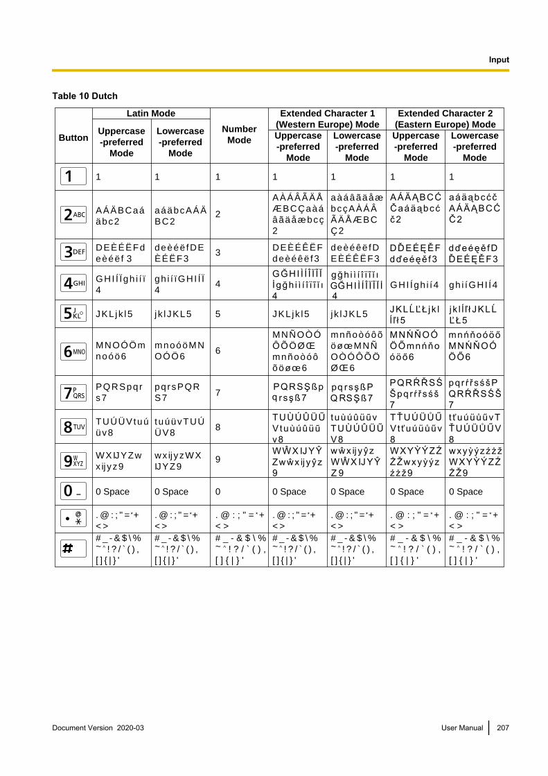
Table 10 Dutch
Button
Latin Mode
Uppercase-preferred
Mode
Uppercase-preferred
Mode
Lowercase-preferred
Mode
Uppercase-preferred
Mode
Lowercase-preferred
Mode
Lowercase-preferred
Mode
Extended Character 1(Western Europe) Mode
Extended Character 2(Eastern Europe) ModeNumber
Mode
1 1 1 1 1 1
A Á Ä B C a á ä b c 2
A À Á Â Ã Ä Å Æ B C Ç a à á â ã ä å æ b c ç 2
a à á â ã ä å æ b c ç A À Á Â Ã Ä Å Æ B C Ç 2
2
D E È É Ë F d e è é ë f 3 3
G H I Í Ï g h i í ï 4 4
J K L j k l 5 5
M N O Ó Ö m n o ó ö 6 6
P Q R S p q r s 7 7
T U Ú Ü V t u ú ü v 8 8
W X IJ Y Z w x ij y z 9
9
0 Space 0
. @ : ; " = + < >
. @ : ; " = + < >
# _ - & $ \ % ~ ! ? / ( ) , [ ] { | } '
1
a á ä b c A Á Ä B C 2
d e è é ë f D E È É Ë F 3
g h i í ï G H I Í Ï 4
j k l J K L 5 J K L j k l 5 j k l J K L 5
m n o ó ö M N O Ó Ö 6
p q r s P Q R S 7
t u ú ü v T U Ú Ü V 8
w x ij y z W X IJ Y Z 9
0 Space 0 Space 0 Space 0 Space 0 Space
. @ : ; " = + < >
. @ : ; " = + < >
. @ : ; " = + < >
. @ : ; " = + < >
. @ : ; " = + < >
# _ - & $ \ % ~ ! ? / ( ) , [ ] { | } '
# _ - & $ \ % ~ ^ ! ? / ` ( ) , [ ] { | } '
# _ - & $ \ % ~ ! ? / ( ) , [ ] { | } '
# _ - & $ \ % ~ ! ? / ( ) , [ ] { | } '
# _ - & $ \ % ~ ^ ! ? / ` ( ) , [ ] { | } '
# _ - & $ \ % ~ ^ ! ? / ` ( ) , [ ] { | } '
D E È É Ê Ë F d e è é ê ë f 3
d e è é ê ë f D E È É Ê Ë F 3
G H I Í g h i í 4 g h i í G H I Í 4
M N Ñ O Ò Ó Ô Õ Ö Ø Œ m n ñ o ò ó ô õ ö ø œ 6
m n ñ o ò ó ô õ ö ø œ M N Ñ O Ò Ó Ô Õ Ö Ø Œ 6
Document Version 2020-03 User Manual 207
Input

Switching the Input ModeEach time [B] or [R] is pressed, the input mode will be switched in the following cycle:• [B] (When Japanese is selected for the display language): Katakana Mode ® Latin mode ® number
mode[B] (When a language other than Japanese, Chinese, or Russian is selected for the displaylanguage): Latin mode ® number mode ® extended character 1 mode ® extended character 2 mode[B] (When Chinese is selected for the display language): Latin mode ® number mode[B] (When Russian is selected for the display language): Cyrillic mode ® number mode ® Latin mode® extended character 1 mode ® extended character 2 mode
• [R] (When an input mode other than Katakana mode or number mode is selected):lowercase-preferred mode ® uppercase-preferred mode
The current input mode is displayed in the guide area.Example: Latin mode and lowercase-preferred mode currently selected
Deleting an Input CharacterPress [Y] to delete an input character. The character deleted depends on the position of the cursor:• If the cursor is to the right of the last character in the line, the last character will be deleted.• If the cursor is within a line of characters, the character to the right of the cursor will be deleted.
Inserting CharactersUse [ ][ ] to move the cursor to the position where you want to insert characters, and then begin input. Thecharacters will be inserted at the location of the cursor.
208 User Manual Document Version 2020-03
Input

Port numbersThe unit uses the following ports in order to make calls.
Note• When using IP/NAT Traversal Mode, refer to the applicable tables for "IP Mode" and "NAT Traversal
Mode".
IP Mode
Purpose ofuse
Transmissionmethod Protocol
Port numberNotesKX-VC1000
KX-VC1300 KX-VC1600 KX-VC2000
RAS
H.323
UDP 1719 1719 1719
H.225 TCP 1720 1720 1720
H.245 TCP 5500 to 5509 5500 to 5519 5500 to 5549 Can bechanged withNAT settings (Page 146)
SIP SIP TCP/UDP 5060 5060 5060
RTP andRTCP forAudio
SIP/H.323
UDP 5100 to 5111 5100 to 5135 5100 to 5191
RTP andRTCP forVideo
UDP 5200 to 5211 5200 to 5235 5200 to 5291
RTP andRTCP forCameraControl
UDP 5300 to 5311 5300 to 5335 5300 to 5391
RTP andRTCP forVideo (Sub)
UDP 5400 to 5411 5400 to 5435 5400 to 5491
BFCP SIP UDP 5800 to 5802 5800 to 5808 5800 to 5822
Document Version 2020-03 User Manual 209
P
o
r
t
n
u
m
b
e
r
s
Port numbers

NAT Traversal Mode
Purpose ofuse
Transmission method Protocol
Port numberNotesKX-VC1000
KX-VC1300 KX-VC1600 KX-VC2000
Managementserver
SIP
TCP 443 443 443 The idle portfor themanagementserver of NATTraversalMode
SIP TCP 15060(5060)
15060(5060)
15060(5060)
The idle portfor the SIPserver of NATTraversalModeIn theconnectionsettings theport can bechanged tothe commonport (5060) (Page 125)
STUN*2 UDP 13478/13479 13478/13479 13478/13479 The idle portfor the STUNserver of NATTraversalMode
RTP andRTCP forAudio*1
UDP 5100 to 5111 5100 to 5135 5100 to 5191 Can bechanged withNAT settings (Page 146)RTP and
RTCP forVideo*1
UDP 5200 to 5211 5200 to 5235 5200 to 5291
RTP andRTCP forCameraControl*1
UDP 5300 to 5311 5300 to 5335 5300 to 5391
RTP andRTCP forVideo (Sub)*1
UDP 5400 to 5411 5400 to 5435 5400 to 5491
BFCP*1 UDP 5800 to 5802 5800 to 5808 5800 to 5822
*1 If a firewall is configured, because it depends on the facing network and devices, allow ANY for the UDP used on the facing side.*2 If *1 is performed, the port for STUN is opened as well.
210 User Manual Document Version 2020-03
Port numbers

Both IP Mode/NAT Traversal Mode
Purpose ofuse Protocol
Port numberNotesKX-VC1000
KX-VC1300 KX-VC1600 KX-VC2000
Telnet TCP 23 23 23 Can bechanged withremoteaccesssettings (Page 162)
Web, ContactList Transfer
TCP 80 80 80
SoftwareUpdate (https)
TCP 443/48750 443/48750 443/48750 Idle port forsoftwaredownloadserver
DHCP UDP 67 67 67 Idle port forDHCP server (the unit usesport number68)
DNS UDP 53 53 53 Idle port forDNS server
Document Version 2020-03 User Manual 211
Port numbers
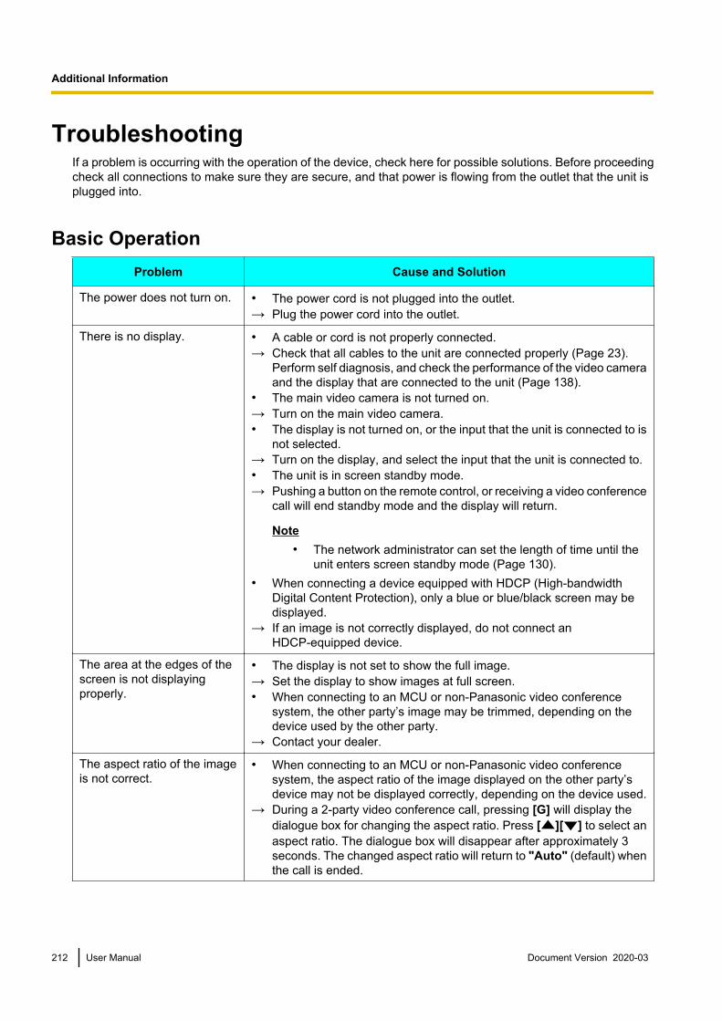
TroubleshootingIf a problem is occurring with the operation of the device, check here for possible solutions. Before proceedingcheck all connections to make sure they are secure, and that power is flowing from the outlet that the unit isplugged into.
Basic OperationProblem Cause and Solution
The power does not turn on. • The power cord is not plugged into the outlet.→ Plug the power cord into the outlet.
There is no display. • A cable or cord is not properly connected.→ Check that all cables to the unit are connected properly (Page 23).
Perform self diagnosis, and check the performance of the video cameraand the display that are connected to the unit (Page 138).
• The main video camera is not turned on.→ Turn on the main video camera.• The display is not turned on, or the input that the unit is connected to is
not selected.→ Turn on the display, and select the input that the unit is connected to.• The unit is in screen standby mode.→ Pushing a button on the remote control, or receiving a video conference
call will end standby mode and the display will return.
Note• The network administrator can set the length of time until the
unit enters screen standby mode (Page 130).• When connecting a device equipped with HDCP (High-bandwidth
Digital Content Protection), only a blue or blue/black screen may bedisplayed.
→ If an image is not correctly displayed, do not connect anHDCP-equipped device.
The area at the edges of thescreen is not displayingproperly.
• The display is not set to show the full image.→ Set the display to show images at full screen.• When connecting to an MCU or non-Panasonic video conference
system, the other party’s image may be trimmed, depending on thedevice used by the other party.
→ Contact your dealer.
The aspect ratio of the imageis not correct.
• When connecting to an MCU or non-Panasonic video conferencesystem, the aspect ratio of the image displayed on the other party’sdevice may not be displayed correctly, depending on the device used.
→ During a 2-party video conference call, pressing [G] will display thedialogue box for changing the aspect ratio. Press [ ][ ] to select anaspect ratio. The dialogue box will disappear after approximately 3seconds. The changed aspect ratio will return to "Auto" (default) whenthe call is ended.
212 User Manual Document Version 2020-03
A
d
d
i
t
i
o
n
a
l
I
n
f
o
r
m
a
t
i
o
n
Additional Information

Problem Cause and Solution
Operation is unresponsive orincorrect.
• Cables or cords may not be connected properly.→ Check that all cables to the unit are connected properly (Page 23).• An error has occurred.→ Turn off the unit and restart it.• There may be a problem with your communication lines.→ Contact your dealer.
The remote control isunresponsive.
• The batteries are depleted.→ Replace with new batteries.• The remote control is being used out of the signal reception range.→ Make sure to use the remote control within the signal reception range.• The remote control ID differs between the unit and the remote control.• If the batteries in the remote control run out (or if they are taken out of
the remote control), and more than 1 day passes, the remote control’sID will be initialised.
→ Change the settings so that the remote control ID of the unit and theremote control match. Perform the following procedure:1. Turn off the unit and restart it.
• The Home screen is displayed. Check the remote control ID ofthe unit (Page 41).
Note• If the remote control ID is not displayed on the Home
screen, contact your dealer.
2. Press and hold [·] and [#] at the same time.
3. Within 2 seconds after you release the buttons, press the number (1 to 3) corresponding to the ID displayed on the Home screen.
Note• If the remote control is still unresponsive after performing
the procedure above, contact your dealer.• Cameras that support the remote control through function are set to
receive signals from a remote control.→ When using the remote control, be sure to point it at the remote control
signal receiver of the camera.→ If you need to send the remote control signals to the unit, set "Remote
control through function" ("FIX Cam's Remote Ctrl Rcvr" forsoftware versions lower than 4.50) to "OFF" (Page 133).
• The unit is set to receive signals from a remote control.→ When using the remote control, be sure to point it at the remote control
signal receiver of the unit (Page 22).→ If you need to send the remote control signals to the camera, set
"Remote control through function" ("FIX Cam's Remote CtrlRcvr" for software versions lower than 4.50) to "ON" (Page 133).
Document Version 2020-03 User Manual 213
Additional Information

Problem Cause and Solution
You cannot control your ownvideo camera (main or subvideo camera) with theremote control.
• Your video camera is not a video camera supported by this unit.→ Use a video camera that is supported by this unit. For details, contact
your dealer.• You are trying to use a function that is not supported by your video
camera. For example, you tried to use the pan function with a videocamera that supports only the zoom function.
→ Check whether your video camera supports the function you are tryingto use.
• When you connect both the main video camera and sub video camerato your unit, you may become unable to control one or both of the videocameras.
→ Disconnect the HDMI cable of the video camera you cannot control,and then connect that video camera’s HDMI cable again.
You cannot control the otherparty’s video camera (main orsub video camera) with theremote control.
• The other party’s video camera is not a video camera supported by thisunit.
→ Ask the other party to use a video camera that is supported by this unit.For details, have the other party contact the dealer.
• "CAM ctrl from remote site(s)" is set to "OFF" on the other party’sunit (Page 133).
→ Ask the other party to set "CAM ctrl from remote site(s)" to "ON" ontheir unit.
• You are trying to use a function that is not supported by the otherparty’s video camera. For example, you tried to use the pan functionwith a video camera that supports only the zoom function.
→ Check whether the other party’s video camera supports the functionyou are trying to use.
• When the other party connects both the main video camera and subvideo camera to their unit, you may become unable to control one orboth of their video cameras.
→ Ask the other party to disconnect the HDMI cable of the video camerayou cannot control, and then connect that video camera’s HDMI cableagain.
• One of the parties is using a unit with an incompatible software version.→ Check the software version of all parties. Update the unit so that the
versions match.• The other party is using a non-Panasonic video conference system.→ If the other party uses a non-Panasonic video conference system, some
operations may not be possible or some operations may not functionas expected.
• Your own site is a Sub Site in a multiple-party video conference callusing a built-in MCU, and so you are not permitted to control the otherparty’s video camera.
→ Set "Camera control transmitting" of "MCU Settings" to "ON".
214 User Manual Document Version 2020-03
Additional Information

Problem Cause and Solution
Cannot connect with anotherparty.
• The LAN cable for LAN1 or LAN2 (KX-VC1600, KX-VC2000) is notconnected properly.
→ Check that it is connected to the unit properly (Page 23). Perform anetwork test by entering the IP address of the other party, and thenconfirm the connection to the other party (Page 138).
• The routing information is incorrect.→ Confirm your network and routing settings, and then contact your
administrator.• The maximum bandwidth setting is incorrect.→ If you are trying to connect to a non-Panasonic video conference
system, a connection might not be possible depending on either youror the other party’s bandwidth settings. Either check your settings andchange them, or have the other party do the same (Page 124).
• The call type setting is incorrect.→ Set the call type setting so that it is the same as the other party’s
(Page 147).• The SIP settings are incorrect.→ Check the SIP settings (Page 148). After you check the SIP settings, if
you still cannot connect to the other party, contact your networkadministrator.
• The ID and password for digest authentication are incorrect.→ Check that the values specified for "Authentication ID" and
"Authentication Password" are correct (Page 148).• The "SIP Transport Protocol" setting is different from the other
party’s.→ Set the "SIP Transport Protocol" setting so that it is the same as the
other party’s (Page 148).• The local site selection is incorrect.→ Confirm the local site. Select the local site that is appropriate for your
usage environment (Page 115).
• The IP address is not entered correctly.→ Confirm that the other party’s IP address is correctly entered.• The SIP URI (or SIP user name), H.323 extension, or H.323 name is
not entered correctly.→ Check whether the SIP URI (or SIP user name), H.323 extension, or H.
323 name of the other party is entered correctly or whether it conformsto the relevant standard.
• The MCU’s conference room number@IP address is not enteredcorrectly.
→ Check whether the conference room number and IP address of theMCU is entered correctly.
Document Version 2020-03 User Manual 215
Additional Information
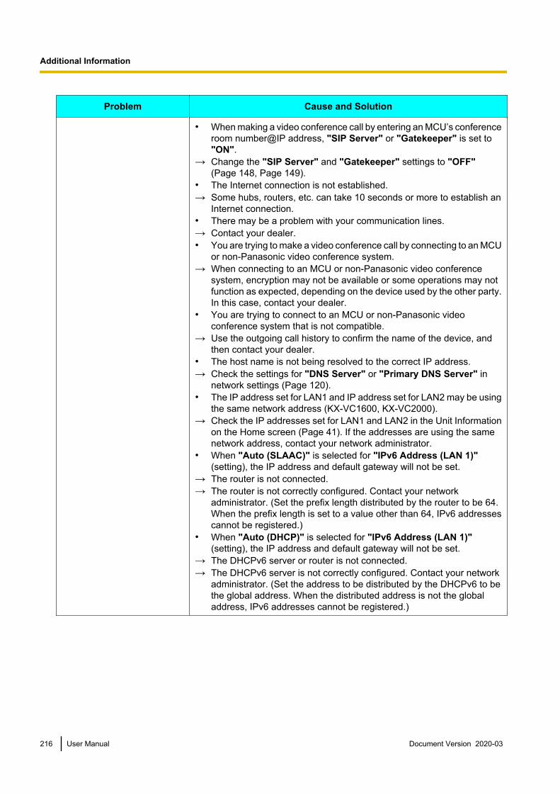
Problem Cause and Solution
• When making a video conference call by entering an MCU’s conferenceroom number@IP address, "SIP Server" or "Gatekeeper" is set to"ON".
→ Change the "SIP Server" and "Gatekeeper" settings to "OFF" (Page 148, Page 149).
• The Internet connection is not established.→ Some hubs, routers, etc. can take 10 seconds or more to establish an
Internet connection.• There may be a problem with your communication lines.→ Contact your dealer.• You are trying to make a video conference call by connecting to an MCU
or non-Panasonic video conference system.→ When connecting to an MCU or non-Panasonic video conference
system, encryption may not be available or some operations may notfunction as expected, depending on the device used by the other party.In this case, contact your dealer.
• You are trying to connect to an MCU or non-Panasonic videoconference system that is not compatible.
→ Use the outgoing call history to confirm the name of the device, andthen contact your dealer.
• The host name is not being resolved to the correct IP address.→ Check the settings for "DNS Server" or "Primary DNS Server" in
network settings (Page 120).• The IP address set for LAN1 and IP address set for LAN2 may be using
the same network address (KX-VC1600, KX-VC2000).→ Check the IP addresses set for LAN1 and LAN2 in the Unit Information
on the Home screen (Page 41). If the addresses are using the samenetwork address, contact your network administrator.
• When "Auto (SLAAC)" is selected for "IPv6 Address (LAN 1)" (setting), the IP address and default gateway will not be set.
→ The router is not connected.→ The router is not correctly configured. Contact your network
administrator. (Set the prefix length distributed by the router to be 64.When the prefix length is set to a value other than 64, IPv6 addressescannot be registered.)
• When "Auto (DHCP)" is selected for "IPv6 Address (LAN 1)" (setting), the IP address and default gateway will not be set.
→ The DHCPv6 server or router is not connected.→ The DHCPv6 server is not correctly configured. Contact your network
administrator. (Set the address to be distributed by the DHCPv6 to bethe global address. When the distributed address is not the globaladdress, IPv6 addresses cannot be registered.)
216 User Manual Document Version 2020-03
Additional Information

Problem Cause and Solution
The image is distorted. • The settings of the hub or router are different to those of the unit.→ Contact your dealer.• Packet loss is occurring. (The network is congested.)→ Check the display of the network status indication (Page 45). If the icon
shows only 0–1 bars continuously, press [STATUS] and check thefields "Loss" and "Bandwidth", then contact your networkadministrator or dealer (Page 106).
• The maximum bandwidth setting is incorrect.→ For multiple-party video conference calls, each site requires at least
256 kbps of bandwidth. For "Max. Bandwidth", set a value equal to orgreater than (256 kbps ´ the number of site connections) (Page 124).
→ If you are trying to connect to an MCU or non-Panasonic videoconference system, depending on the other party’s device, the imagemay be distorted due to lack of bandwidth. In this case, contact yourdealer.
• There may be a problem with your communication lines.→ Contact your dealer.
The maximum bandwidthchanges during a videoconference call.
• The maximum bandwidth during a video conference call adjusts to thatof the party that has set the lowest bandwidth for the maximumbandwidth setting among all participating parties.
→ If there is a problem with your communication lines, contact your dealer.
The computer or sub videocamera’s video is notdisplayed.
• Cables or cords may not be connected properly.→ Make sure all connections to the unit are correct (Page 90). On the
Home screen, press [PC] or [CAMERA SUB] and then check thecomputer’s screen or sub video camera’s image.
• The computer’s display resolution is incompatible with the unit.→ Set your computer’s resolution to a setting compatible with the unit
(Page 90).
Document Version 2020-03 User Manual 217
Additional Information

AudioProblem Cause and Solution
The other party cannot hearyour voice.
• The microphone cable is not properly connected.→ Check that the microphone is properly connected to the unit (Page 23).
Perform self diagnosis, and check the performance of the microphonesthat are connected to the unit (Page 138).
• The microphone is muted.→ Press [MIC MUTE] on the remote control, or press the MIC Mute button
on the Boundary Microphone to unmute the microphone (Page 87).• "Default MIC Mute set (Make Call)" is set to "ON".• "Default MIC Mute set (Incoming)" is set to "ON".→ The microphone is muted at the time when communication starts.
Confirm the settings (Page 125).• The microphone is being obstructed.→ During the video conference call, do not block the microphone with your
hand or other object.• You are too far from a microphone.→ Speak close to a microphone.• More than 5 Digital Boundary Microphones are connected in cascade.→ Connect no more than 4 Digital Boundary Microphones at a time.• A headset is connected.→ When a headset is connected, audio input from Boundary Microphones
is disabled. To use the Boundary Microphones, disconnect the headset.• There may be a problem with your communication lines.→ Contact your dealer.
The sound cuts out. • You are too far from a microphone.→ Speak close to a microphone.• The microphone or unit is being moved during a video conference call.→ Do not move the unit or the microphone during a video conference call.• The microphone is being obstructed.→ During the video conference call, do not block the microphone with your
hand or other object.• There may be a problem with your communication lines.→ Contact your dealer.
218 User Manual Document Version 2020-03
Additional Information
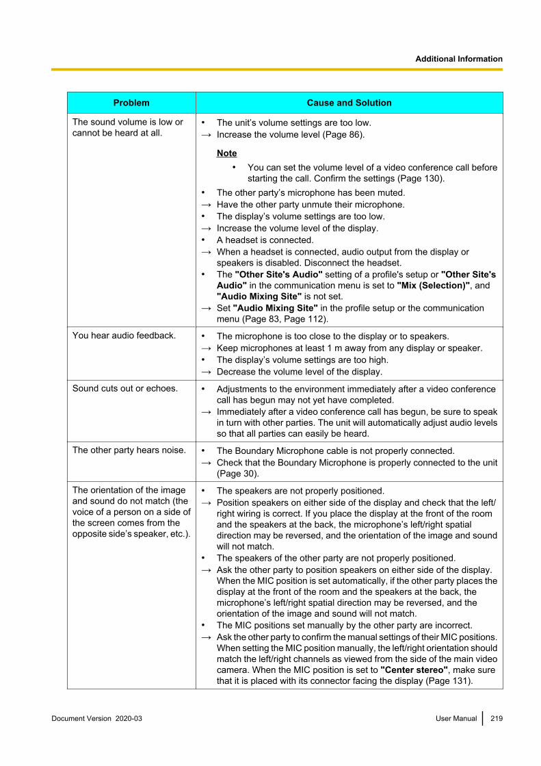
Problem Cause and Solution
The sound volume is low orcannot be heard at all.
• The unit’s volume settings are too low.→ Increase the volume level (Page 86).
Note• You can set the volume level of a video conference call before
starting the call. Confirm the settings (Page 130).• The other party’s microphone has been muted.→ Have the other party unmute their microphone.• The display’s volume settings are too low.→ Increase the volume level of the display.• A headset is connected.→ When a headset is connected, audio output from the display or
speakers is disabled. Disconnect the headset.• The "Other Site's Audio" setting of a profile's setup or "Other Site's
Audio" in the communication menu is set to "Mix (Selection)", and"Audio Mixing Site" is not set.
→ Set "Audio Mixing Site" in the profile setup or the communicationmenu (Page 83, Page 112).
You hear audio feedback. • The microphone is too close to the display or to speakers.→ Keep microphones at least 1 m away from any display or speaker.• The display’s volume settings are too high.→ Decrease the volume level of the display.
Sound cuts out or echoes. • Adjustments to the environment immediately after a video conferencecall has begun may not yet have completed.
→ Immediately after a video conference call has begun, be sure to speakin turn with other parties. The unit will automatically adjust audio levelsso that all parties can easily be heard.
The other party hears noise. • The Boundary Microphone cable is not properly connected.→ Check that the Boundary Microphone is properly connected to the unit
(Page 30).
The orientation of the imageand sound do not match (thevoice of a person on a side ofthe screen comes from theopposite side’s speaker, etc.).
• The speakers are not properly positioned.→ Position speakers on either side of the display and check that the left/
right wiring is correct. If you place the display at the front of the roomand the speakers at the back, the microphone’s left/right spatialdirection may be reversed, and the orientation of the image and soundwill not match.
• The speakers of the other party are not properly positioned.→ Ask the other party to position speakers on either side of the display.
When the MIC position is set automatically, if the other party places thedisplay at the front of the room and the speakers at the back, themicrophone’s left/right spatial direction may be reversed, and theorientation of the image and sound will not match.
• The MIC positions set manually by the other party are incorrect.→ Ask the other party to confirm the manual settings of their MIC positions.
When setting the MIC position manually, the left/right orientation shouldmatch the left/right channels as viewed from the side of the main videocamera. When the MIC position is set to "Center stereo", make surethat it is placed with its connector facing the display (Page 131).
Document Version 2020-03 User Manual 219
Additional Information

System SettingsProblem Cause and Solution
The settings of the unit cannotbe changed.
• A video conference call is in progress.→ Make settings after ending the current video conference call.• A video conference call is incoming.→ A dialogue box will be displayed asking whether to answer the call.
Press [END] to disconnect the incoming call, and then configure thesetting on the unit.
→ If a video conference call is received when editing settings on the unit,a dialogue box will be displayed asking whether to answer the callwithout saving the settings, and you will temporarily be unable to editthe settings. To continue editing, reject the call.
If These Messages AppearMessage Cause and Solution
Call failed. Encryptionsettings (On/Off) must match.Please change the encryptionsetting on one side and tryagain.
• The encryption settings do not match those of the other party in a videoconference call.
→ Change the encryption settings to match those of the other party (Page 125, Page 125, Page 144).
Call Failed due to wrongencryption key. Pleasecontact your installer.
• The encryption key settings do not match those of the other party in avideo conference call.
→ Ensure your encryption key setting matches the other party’s (Page 145).
Check the Main Camera connection.
• A cable or cord is not properly connected.→ Check that all cables to the unit are connected properly (Page 23).• The signal input from the main video camera is invalid.→ A valid signal cannot be received from the connected main video
camera. Contact your dealer.
Unable to register, the contact list is full.
• The contact list has reached its maximum capacity.→ Delete unneeded contacts (Page 108).
Invalid IP Address. • The format of the IP address that you entered is invalid.→ Enter the IPv4 address correctly, in the format XXX.XXX.XXX.XXX
(decimal values separated by periods). For values of only 1 or 2 digits,enter these numbers as they are. Do not enter like [.001].Example: The IP address is [192.168.0.1].– Correct entry: [192.168.0.1]– Wrong entry: [192.168.000.001]Multicast or broadcast addresses cannot be used.
→ Enter a valid IPv6 address. For the IPv6 address input format, refer toPage 47.
220 User Manual Document Version 2020-03
Additional Information

Message Cause and Solution
Invalid Subnet mask. • The input subnet mask is invalid.→ Enter a valid subnet mask. For values of only 1 or 2 digits, enter these
numbers as they are. Do not enter like [.000].Example: The subnet mask is [255.255.255.0].– Correct entry: [255.255.255.0]– Wrong entry: [255.255.255.000]
Invalid Default Gateway. • The input default gateway is invalid.→ Enter a valid default gateway for IPv4 addresses. For values of only 1
or 2 digits, enter these numbers as they are. Do not enter like [.001].Example: The default gateway is [192.168.0.1].– Correct entry: [192.168.0.1]– Wrong entry: [192.168.000.001]
→ Enter a valid default gateway for IPv6 addresses. For the IPv6 addressinput format, refer to Page 47.
Invalid Date/Time. • Enter a date within the valid parameters.→ Enter a date between January 1, 2019 and December 31, 2035.
PC is not connected.Check the connection.
• A cable or cord is not properly connected.→ Check that all cables to the unit are connected properly (Page 34).• The computer is not turned on.→ Turn on the computer.• The computer is not set to output from its external monitor video out
port.→ Change the computer’s settings so that video is output from the external
monitor port.
Sub-Camera is not connected.Check the connection.
• A cable or cord is not properly connected.→ Check that all cables to the unit are connected properly (Page 34).• The sub video camera is not turned on.→ Turn on the sub video camera.
Sub-Camera source is not compatible.
• A cable or cord is not properly connected.→ Check that all cables to the unit are connected properly (Page 34).• The signal input from the sub video camera is invalid.→ A valid signal cannot be received from the connected sub video camera.
Contact your dealer.
Different video frequency or resolution of TV is connected with HDMI n.
Note• "n" is displayed as the
HDMI terminal’snumber (1 to 3).
• A display with a video frequency different from that of the unit wasconnected.
→ Match the unit’s video frequency to the display being used.• A display that does not support 1920 1080 resolution was connected.→ Use a display that supports 1080 resolution.
Note• The resolution of all connected displays will be lowered. When the
terminal connected to the display indicated in the message isdisconnected, the resolution will return to full HD.
• The output for the terminal indicated in the message will display as"Unsupported" in the unit information screen.
Document Version 2020-03 User Manual 221
Additional Information

Message Cause and Solution
Check display resolution. • The computer’s display resolution is incompatible with the unit.→ Set your computer’s resolution to a setting compatible with the unit
(Page 90).
n is already in use.
Note• The IP address is
represented by n.
• On the network you are using, another device is already using the IPaddress you have input for the unit.
→ Make sure that all devices on the network have unique IP addressesassigned.
Cooling Fan Malfunction.Please turn off the system and call for service.
• The CPU cooling fan within the device has stopped (displayed formodels except the KX-VC2000).
→ Quickly turn off the power. Contact your dealer.
Cooling Fan Malfunction.Power automatically turns off.
• The CPU cooling fan within the device has stopped (displayed for theKX-VC2000).
→ Contact your dealer.
Call Failed due to unsupported product or other error.
• An unsupported feature was used.→ Check the software version of all parties. Update the unit so that the
versions match.For details about supported versions and features, contact your dealer.
• Connection to an unsupported MCU or non-Panasonic videoconference system was attempted.
→ For details about supported MCUs and non-Panasonic videoconference systems, contact your dealer.
Call disconnected due tocodec negotiation failed.
• The other party’s device uses an unsupported codec.→ Have the other party check their settings.
222 User Manual Document Version 2020-03
Additional Information
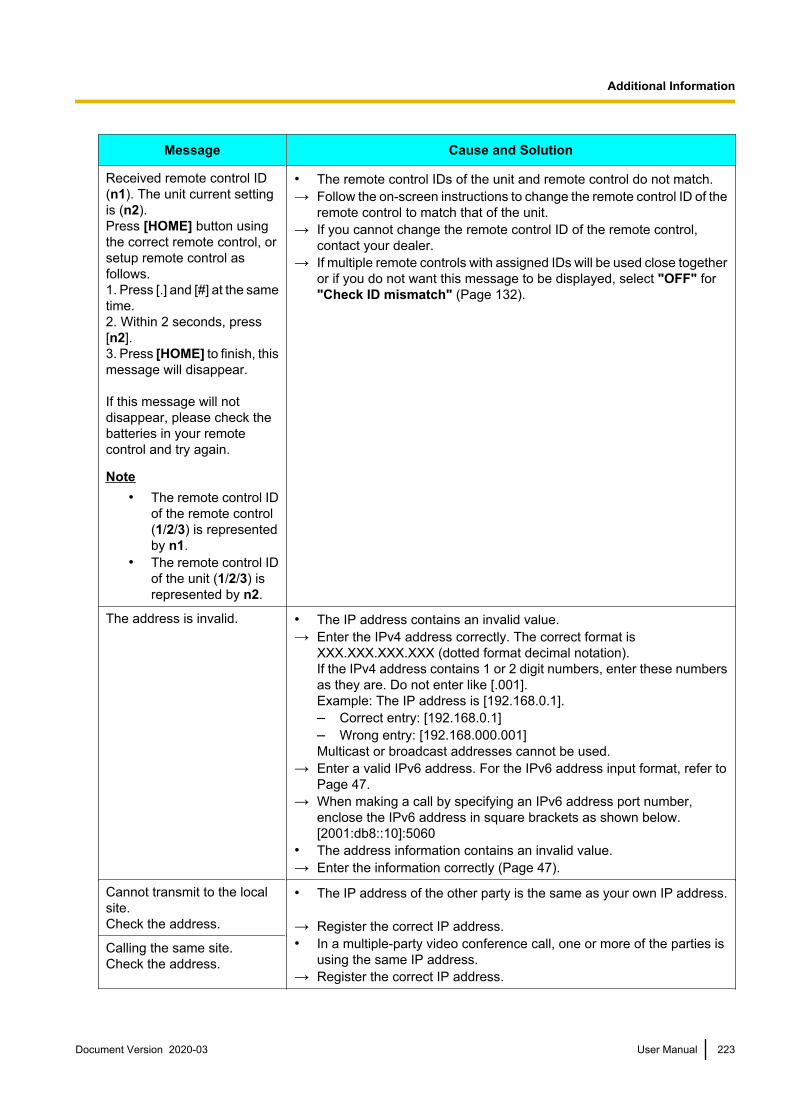
Message Cause and Solution
Received remote control ID (n1). The unit current settingis (n2).Press [HOME] button usingthe correct remote control, orsetup remote control asfollows.1. Press [.] and [#] at the sametime.2. Within 2 seconds, press[n2].3. Press [HOME] to finish, thismessage will disappear.
If this message will notdisappear, please check thebatteries in your remotecontrol and try again.
Note• The remote control ID
of the remote control (1/2/3) is representedby n1.
• The remote control IDof the unit (1/2/3) isrepresented by n2.
• The remote control IDs of the unit and remote control do not match.→ Follow the on-screen instructions to change the remote control ID of the
remote control to match that of the unit.→ If you cannot change the remote control ID of the remote control,
contact your dealer.→ If multiple remote controls with assigned IDs will be used close together
or if you do not want this message to be displayed, select "OFF" for"Check ID mismatch" (Page 132).
The address is invalid. • The IP address contains an invalid value.→ Enter the IPv4 address correctly. The correct format is
XXX.XXX.XXX.XXX (dotted format decimal notation).If the IPv4 address contains 1 or 2 digit numbers, enter these numbersas they are. Do not enter like [.001].Example: The IP address is [192.168.0.1].– Correct entry: [192.168.0.1]– Wrong entry: [192.168.000.001]Multicast or broadcast addresses cannot be used.
→ Enter a valid IPv6 address. For the IPv6 address input format, refer toPage 47.
→ When making a call by specifying an IPv6 address port number,enclose the IPv6 address in square brackets as shown below.[2001:db8::10]:5060
• The address information contains an invalid value.→ Enter the information correctly (Page 47).
Cannot transmit to the local site.Check the address.
• The IP address of the other party is the same as your own IP address.
→ Register the correct IP address.• In a multiple-party video conference call, one or more of the parties is
using the same IP address.→ Register the correct IP address.
Calling the same site.Check the address.
Document Version 2020-03 User Manual 223
Additional Information

Message Cause and Solution
Invalid Primary DNS Serveraddress.
• The IP address contains an invalid value.→ Enter the IPv4 address correctly. The correct format is
XXX.XXX.XXX.XXX (dotted format decimal notation).If the IPv4 address contains 1 or 2 digit numbers, enter these numbersas they are. Do not enter like [.001].Example: The IP address is [192.168.0.1].– Correct entry: [192.168.0.1]– Wrong entry: [192.168.000.001]Multicast or broadcast addresses cannot be used.
Invalid Secondary DNSServer address.
Please enter differentaddresses for each DNSServer.
• The addresses of the primary and secondary DNS servers are thesame.
→ Enter different IP addresses (Page 121).
Invalid PrimaryDNS Server address (IPv6).
• The format of the IP address that you entered is invalid.→ Enter a valid IPv6 address. For the IPv6 address input format, refer to
Page 47.Invalid SecondaryDNS Server address (IPv6).
Please enter differentaddressesfor each DNS Server (IPv6).
• The addresses of the IPv6 primary DNS server and IPv6 secondaryDNS server are the same.
→ Enter different IPv6 addresses (Page 122).
Connection will be closed inn seconds.Press "YES" to continue.
Note• The message first
appears when oneminute remains and"60" is displayed forn. Then, theremaining time startsto decrease.
• The time set for "Call Limit time" has one minute remaining (Page 125).
→ If you select "Yes", you can extend the call limit time for the amountset for "Call Limit time". If you select "No", the call is disconnected.
Unable to connect to network. (XXXX XXXX)
Note• An error code
(consisting ofnumerals) isdisplayed in "XXXXXXXX".
• The LAN cable is not connected properly, and therefore you cannotmake a video conference call.
→ Check that the LAN cable is connected to the unit properly. Try makinga call again, after confirming that the IP address, SIP user name, etc.,is displayed on the Home screen. If transmission still fails, make a noteof the error code and contact your dealer.
Note• If transmission fails due to the LAN cable not being connected
properly, it may take up to 10 minutes before the IP address, SIPuser name, etc., is displayed and video conference calls can bemade after reconnecting the LAN cable.
224 User Manual Document Version 2020-03
Additional Information

Message Cause and Solution
Disconnected. • When connecting to an MCU or non-Panasonic video conferencesystem, the video conference call was disconnected.
→ When connecting to an MCU or non-Panasonic video conferencesystem, encryption may not be available or some operations may notfunction as expected, depending on the device used by the other party.In this case, contact your dealer.
• When connecting to an MCU or non-Panasonic video conferencesystem, the video conference call was disconnected for an unknownreason.
→ Wait a while and then try making the video conference call again. Ifvideo conference calls get disconnected repeatedly, contact yourdealer.
Feature is not available with current connection.
• The other party cannot display the computer’s screen because theirdisplay does not support the selected resolution.
→ Change the resolution setting to a resolution that is supported by theother party.
→ Contact your network administrator.• Tone signals could not be sent because the other party’s device does
not support tone signals.→ Ask the other party to check their configuration.
Invalid Operation. • Your video camera is not a video camera supported by this unit.→ Use a video camera that is supported by this unit. For details, contact
your dealer.• You are trying to use a function that is not supported by your video
camera. For example, you tried to use the pan function with a videocamera that supports only the zoom function.
→ Check whether your video camera supports the function you are tryingto use.
• You are trying to change the call type during a video conference callusing the selected local site.
→ Stop the video conference call using the selected local site, and thenchange the call type.
Invalid SIP Server Address. • The format of the SIP server address that you entered is invalid.→ Enter the SIP server address for IPv4 addresses correctly. Enter the
SIP server address as XXX.XXX.XXX.XXX (values separated bydecimals). For values of only 1 or 2 digits, enter these numbers as theyare. Do not enter like [.001].Example: The IP address is [192.168.0.1].– Correct entry: [192.168.0.1]– Wrong entry: [192.168.000.001]Multicast or broadcast addresses cannot be used.
→ Enter a valid IPv6 address. For the IPv6 address input format, refer toPage 47.
Invalid SIP Domain Name. • The format of the SIP domain name that you entered is invalid.→ Enter a standards-compliant value. For details, contact your network
administrator.
Document Version 2020-03 User Manual 225
Additional Information

Message Cause and Solution
Invalid WAN IP Address. • The format of the router’s WAN IP address that you entered is invalid.→ Enter the WAN IP address correctly, in the format XXX.XXX.XXX.XXX
(decimal values separated by periods). For values of only 1 or 2 digits,enter these numbers as they are. Do not enter like [.001].Example: The IP address is [192.168.0.1].– Correct entry: [192.168.0.1]– Wrong entry: [192.168.000.001]Multicast or broadcast addresses cannot be used.
Invalid Gatekeeper Address. • The format of the gatekeeper’s IP address that you entered is invalid.→ Enter the gatekeeper address for IPv4 addresses correctly. Enter the
gatekeeper address as XXX.XXX.XXX.XXX (values separated bydecimals). For values of only 1 or 2 digits, enter these numbers as theyare. Do not enter like [.001].Example: The IP address is [192.168.0.1].– Correct entry: [192.168.0.1]– Wrong entry: [192.168.000.001]Multicast or broadcast addresses cannot be used.
→ Enter a valid IPv6 address. For the IPv6 address input format, refer toPage 47.
Failed to save data. • You are using a USB memory device that is not compatible with theunit.
→ Use a USB memory device compatible with the unit (Page 163).• There is not enough free space on the USB memory device you are
using.→ Confirm the USB memory device has sufficient free space (at least
50 MB) before using it.
Invalid Operation. Initialsetting is not completed.
• In local site settings, you tried to select and save a connection modewithout completing network settings.
→ Before making local site settings, change the connection mode (Page 146) and make network settings (Page 120).
Network error has occurred.Check the network. (LANn)
Note• The LAN number (1 or
2) is displayed where"n" is.
• A problem has occurred on the network such as a network loop.→ Check the LAN cables and network equipment. If it has been detected
that the network problem has resolved, the following messages aredisplayed. In this case press [ENTER].The network is normal.Press [ENTER] and restart the system.
System Error! Please restartthe system. If error messageappears again, pleasecontact Installer or ServiceAdministrator. * System mayrestart automatically.
• The unit’s internal software failed to start up.• The unit failed to write data to the internal flash memory.→ If the unit does not restart automatically after 20 seconds, restart the
unit by turning off its power, then turning it back on. If the same messageis displayed after resetting the unit, contact your dealer.
Failed to obtain the WAN IPAddress.
• There was an error in receiving the WAN address from the externalserver.
→ Contact your dealer.
226 User Manual Document Version 2020-03
Additional Information

Message Cause and Solution
Software update failed.(3996 0BBB)
• The USB memory device does not contain the appropriate firmware.• The firmware is incorrect.→ Confirm that the correct firmware is saved to the USB memory device.
For details about the firmware, contact your dealer.Software update failed.(3996 0BBB)Restart the system.
Administrative rights arerequired for this operation.
• The operation has been restricted in the administrator menu.→ Contact your network administrator.
Invalid Operation.This site is not an MCU site.
• A menu option that cannot be executed is selected.→ During a one-to-one connection video conference, operations for a
multiple-party video conference call cannot be performed.
Invalid Operation.Content is being shared.
• A menu option that cannot be executed is selected.→ When contents are being shared using single-stream communication
during a multiple-party video conference call using a built-in MCU, atthe Main Site the communication menu items "Make a call" and "MainPosition set." cannot be selected.
Invalid Operation.USB recording is in progress.
• An operation or menu option that cannot be executed during USBrecording is selected.
→ Operate after stopping USB recording.
There is a problem with theUSBflash drive write speed.Replace the USB flash drive.
• An error has occurred when writing the recording data.→ The write speed of a USB memory device may decline due to
deterioration over use in long periods or other causes. Replace the USBmemory device. If you continue recording without replacing the USBmemory device, recorded images may be corrupted or cut out.
Invalid Operation.Not enough free space onUSBflash drive.
• There is insufficient free space in the connected USB memory device.→ Connect a USB memory device with sufficient free space according to
your required recording time and quality. For the required amount offree space of different qualities, refer to Page 188.
Invalid Operation.The device is in USB DeviceMode.
• You cannot make or receive calls or use a USB memory device whilein USB Device Mode.
→ Set "USB Device Mode" to "OFF" (Page 135).
Invalid Operation.The device is in Web HybridMode.
• You cannot use a USB memory device while in Web Hybrid Mode.→ Set "Web Hybrid Mode" to "OFF" (Page 136).
Invalid Operation.The function needs activation.
• A menu option that cannot be executed unless the feature is enhancedis selected.
→ Confirm the required activation key (Page 20) and refer to"Enhancement" (Page 159) to enhance the feature. For details,contact your dealer.
Version of Contact List ismismatch.Please update the software.
• The software version of the server and client for the contact list aredifferent.
→ The software for the server or client for the contact list needs to beupdated. For details, contact your dealer.
Document Version 2020-03 User Manual 227
Additional Information

Message Cause and Solution
A new Contact List update isavailable.
Server is during call.It can not be executed thistime.
• Although new contact lists are available on the contact list server, theycannot be sent to the client because the server is on a call.
→ Wait for a while and then manually check the contact list of the server.(Page 159)
Registration Page of KX-VC Series NAT Traversal ServiceBasic Operation
Problem Cause and Solution
The language displayed onthe screen is a foreignlanguage.
• The language setting is incorrect.→ In the upper right of the login screen, select your preferred language
from the drop-down list (Page 169).
I cannot log in to the deviceapplication screen.
• The characters displayed in the image were not entered correctly.→ Check that the capitalization of characters is correct, and then try
entering them again.→ Check that you have not entered any unused characters, and then try
entering them again. The following characters are not used.– Uppercase letters: I O– Lowercase letters: c i j l o s u v w x z
If These Messages AppearMessage Cause and Solution
Invalid Activation Keyentered.
• The Activation Key No. or the Registration ID you entered is incorrect.→ Check the information written on the activation key to ensure it is
entered correctly.
Activation Key already registered.
• The Activation Key No. and Registration ID you entered is already inuse by another HD Visual Communication Unit.
• You entered an Activation Key No. and Registration ID that have beenused for registration in the past.
→ Enter the information written on an activation key that has not beenused yet. If the message still appears, contact your dealer.
This Trial licence already registered.
• You are trying to use a different activation key after completingregistration using the included activation key.
→ Do not use an activation key other than the one included with theproduct.
228 User Manual Document Version 2020-03
Additional Information

KX-VC Series NAT Traversal Service for this DeviceProblem Cause and Solution
I registered a RegistrationKey, but I cannot make avideo conference call usingKX-VC Series NAT TraversalService.
• The connection mode is not set to "NAT Traversal Mode".→ Set the connection mode to "NAT Traversal Mode" (Page 146).
After registering aRegistration Key andrestarting the unit, theTerminal ID is not displayed inthe upper right of the Homescreen even after 5 minutes.
• The LAN cable is not connected correctly.→ Check that it is connected to the unit properly.• Router settings for your Internet connection are incorrect.→ Set your router correctly, following the router’s documentation, and in
accordance with setting information supplied by your Internet provider.• Packet filtering or port forwarding is enabled on the router.→ Disable these features on the router. For details, refer to your router’s
documentation.
I extended the service period,but the Terminal ID is notdisplayed on the Homescreen.
• You did not restart the unit after registering on the KX-VC Series NATTraversal Service registration page. Restarting the unit is necessary toapply the registration information.
→ Turn off power to the unit, and then turn it back on to restart the unit.
The service period has notbeen extended even though aservice period extension wasperformed.
• You did not restart the unit after registering on the KX-VC Series NATTraversal Service registration page. Restarting the unit is necessary toapply the registration information.
→ Turn off power to the unit, and then turn it back on to restart the unit.
If a message from the KX-VC Series NAT Traversal Service isdisplayed
Message Cause and Solution
Failed Registration Key code authentication.
• You are trying to register an invalid Registration Key.→ Recheck the information of the Registration Key that was issued
(Page 170), then repeat the registration (Page 159).
Document Version 2020-03 User Manual 229
Additional Information

Message Cause and Solution
Unable to connect to network. (XXXX XXXX)
Note• An error code
(containingalphanumericcharacters) isdisplayed in "XXXXXXXX".
• The router or the LAN cable is not connected correctly to the unit, andtherefore you cannot make a video conference call. The following tableexplains the error codes:
Error Code Explanation
01000003 The DHCP lease expired.
10000001 Registration to the gate keeper failed.
01000006 There was a change due to an extension of the DHCP lease.
01000007 The DHCP network information is invalid.
Registration to the SIP server failed.05000008
TCP connection was lost in NAT Traversal Mode.
05000009
→ Check that the router and/or LAN cable are correctly connected to theunit. (Directly connect the router to the unit and check operation. Alsotry replacing the LAN cable, and then check operation.) If the devicesare connected correctly, the router’s settings may be incorrect, or theunit may be malfunctioning. Contact your dealer.
Note• When transmission between the unit and the router is interrupted
because the LAN cable is connected incorrectly, it may take up to10 minutes before the Terminal ID is displayed and videoconference calls can be made after reconnecting the LAN cable.
Service will expire soon! Please purchase and register new Activation Key Card to avoid interruption of NAT Traversal Service. Expiration date could be checked at Enhancement screen.
• Your service period may have passed 3 months.→ Purchase a new activation key, and extend the service period
(Page 171).
Service expired! Please purchase and register new Activation Key Card to activate NAT Traversal Service.
• The service period has expired.→ If within 6 months since expiration:
Purchase a new activation key, and extend the service period (Page 171).
→ If 6 months or more since expiration:Purchase a new activation key, and then acquire a new RegistrationKey, and re-register to the unit (Page 159, Page 168).
Note• To determine whether it has been more than 6 months since the
service period expired, see "Checking Enhanced Features".
230 User Manual Document Version 2020-03
Additional Information
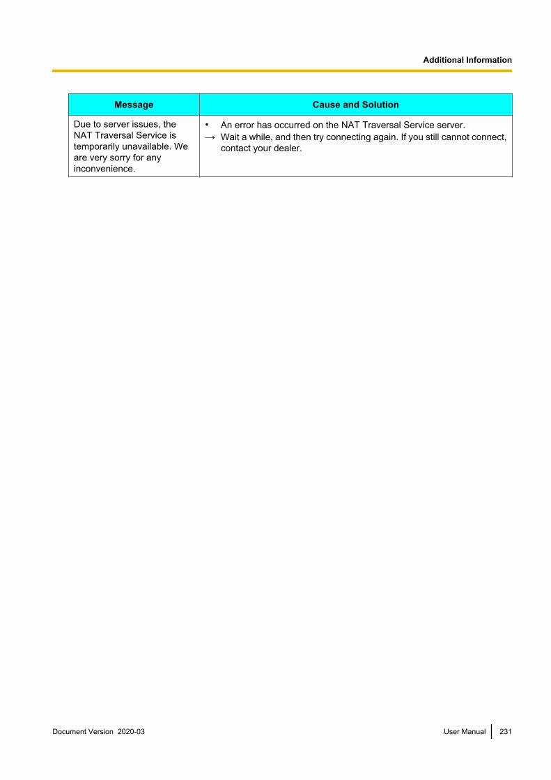
Message Cause and Solution
Due to server issues, the NAT Traversal Service is temporarily unavailable. We are very sorry for any inconvenience.
• An error has occurred on the NAT Traversal Service server.→ Wait a while, and then try connecting again. If you still cannot connect,
contact your dealer.
Document Version 2020-03 User Manual 231
Additional Information

System SpecificationsUnit KX-VC2000 KX-VC1600 KX-VC1300 KX-VC1000
Communication Protocol SIP, H.323
Video Compression Method H.261 (Main Stream only), H.263, H.263+, H.263++ (reception only),H.264 High Profile, H.264 Baseline Profile
Audio Compression Method G.711 µ-law, A-law (3.4 kHz@64 kbps)G.722 (7.0 kHz@64 kbps)G.722.1 (7.0 kHz@32 kbps)G.722.1 Annex C (14.0 kHz@48 kbps/24 kbps)MPEG-4 AAC-LD Mono (7.0 kHz@32 kbps, 14.0 kHz@64 kbps,22.0 kHz@96 kbps)MPEG-4 AAC-LD Stereo (14.0 kHz@64 kbps, 22.0 kHz@96 kbps)
No. of Channels:G.711/G.722/G.722.1/G.722.1 Annex C: 1MPEG-4 AAC-LD Mono: 1/MPEG-4 AAC-LD Stereo: 2
Remote Camera Control H.224, H.281 (Zoom/Pan/Tilt/Preset)
DualStream
Method H.239 (H.323), BFCP (SIP)
No. of Displays 3 displays 2 displays 1 display (Expandableto 2 displays)
SupportedResolution andFrame Rate
Main: Maximum 1080p 30 frames/sec.*1
Sub: Maximum 1080p 30 frames/sec.*1
Encryption SRTP (AES 128-bit), H.235 (AES 128-bit)
Other H.460
Communication Bandwidth 256 kbps–24 Mbps
256 kbps–18 Mbps
Video CompatibleResolutions*2
176 ´ 144p, 352 ´ 240p, 352 ´ 288p, 512 ´ 288p, 640 ´ 480p,704 ´ 480p, 704 ´ 576p, 768 ´ 432p, 800 ´ 600p, 1024 ´ 768p,1280 ´ 720p, 1280 ´ 768p, 1280 ´ 800p, 1920 ´ 1080p
Frame Rate Maximum 60 frames/sec. (When using H.264 1080p)
Screen Display Full screen, Picture in Picture, Picture with Picture, Side by Side
Audio Echo Canceller, Auto Gain Control, Stationary Noise Reduction, LipSync, Equalizer, Mic Mute
232 User Manual Document Version 2020-03
S
p
e
c
i
f
i
c
a
t
i
o
n
s
Specifications
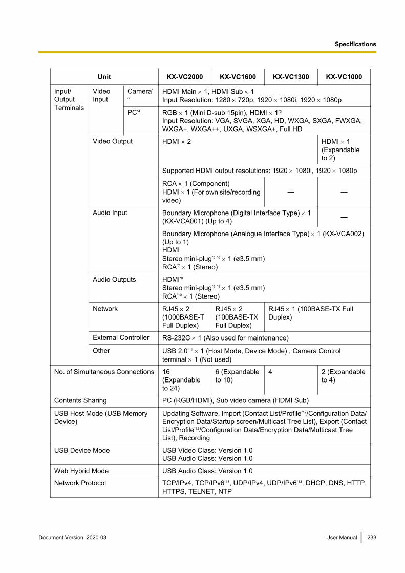
Unit KX-VC2000 KX-VC1600 KX-VC1300 KX-VC1000
Input/OutputTerminals
VideoInput
Camera*
3HDMI Main ´ 1, HDMI Sub ´ 1Input Resolution: 1280 ´ 720p, 1920 ´ 1080i, 1920 ´ 1080p
PC*4 RGB ´ 1 (Mini D-sub 15pin), HDMI ´ 1*3
Input Resolution: VGA, SVGA, XGA, HD, WXGA, SXGA, FWXGA,WXGA+, WXGA++, UXGA, WSXGA+, Full HD
Video Output HDMI ´ 2 HDMI ´ 1(Expandableto 2)
Supported HDMI output resolutions: 1920 ´ 1080i, 1920 ´ 1080p
RCA ´ 1 (Component)HDMI 1 (For own site/recordingvideo)
— —
Audio Input Boundary Microphone (Digital Interface Type) ´ 1 (KX-VCA001) (Up to 4) —
Boundary Microphone (Analogue Interface Type) ´ 1 (KX-VCA002) (Up to 1)HDMIStereo mini-plug*5 *6 ´ 1 (ø3.5 mm)RCA*7 ´ 1 (Stereo)
Audio Outputs HDMI*8
Stereo mini-plug*5 *9 ´ 1 (ø3.5 mm)RCA*10 ´ 1 (Stereo)
Network RJ45 ´ 2 (1000BASE-TFull Duplex)
RJ45 ´ 2 (100BASE-TXFull Duplex)
RJ45 ´ 1 (100BASE-TX FullDuplex)
External Controller RS-232C ´ 1 (Also used for maintenance)
Other USB 2.0*11 ´ 1 (Host Mode, Device Mode) , Camera Controlterminal ´ 1 (Not used)
No. of Simultaneous Connections 16 (Expandableto 24)
6 (Expandableto 10)
4 2 (Expandableto 4)
Contents Sharing PC (RGB/HDMI), Sub video camera (HDMI Sub)
USB Host Mode (USB MemoryDevice)
Updating Software, Import (Contact List/Profile*12/Configuration Data/Encryption Data/Startup screen/Multicast Tree List), Export (ContactList/Profile*12/Configuration Data/Encryption Data/Multicast TreeList), Recording
USB Device Mode USB Video Class: Version 1.0USB Audio Class: Version 1.0
Web Hybrid Mode USB Audio Class: Version 1.0
Network Protocol TCP/IPv4, TCP/IPv6*13, UDP/IPv4, UDP/IPv6*13, DHCP, DNS, HTTP,HTTPS, TELNET, NTP
Document Version 2020-03 User Manual 233
Specifications
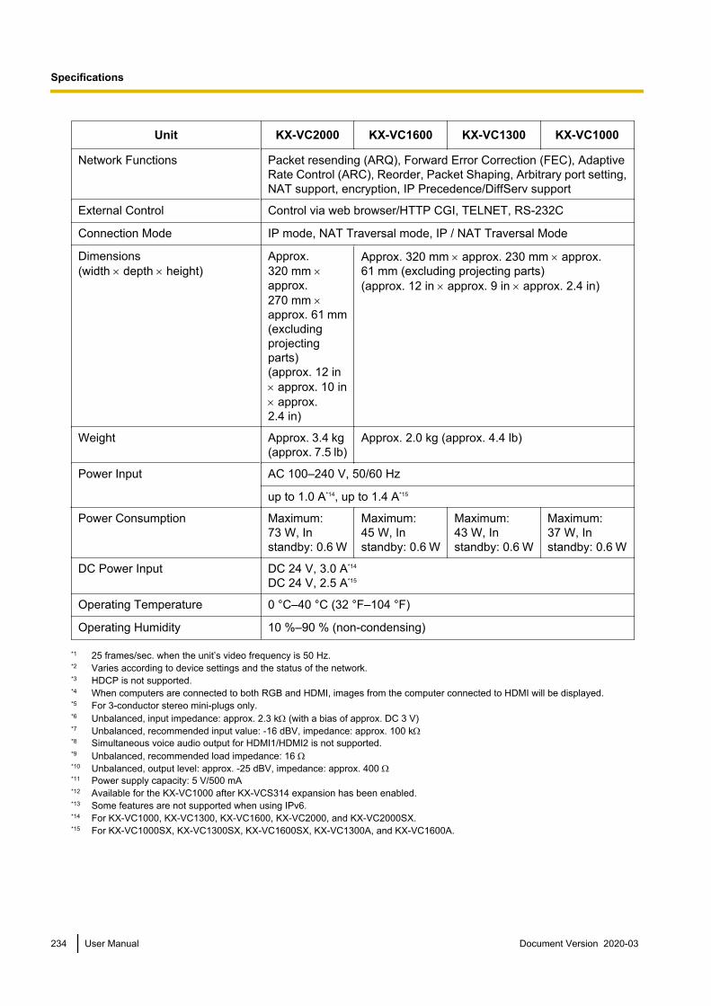
Unit KX-VC2000 KX-VC1600 KX-VC1300 KX-VC1000
Network Functions Packet resending (ARQ), Forward Error Correction (FEC), AdaptiveRate Control (ARC), Reorder, Packet Shaping, Arbitrary port setting,NAT support, encryption, IP Precedence/DiffServ support
External Control Control via web browser/HTTP CGI, TELNET, RS-232C
Connection Mode IP mode, NAT Traversal mode, IP / NAT Traversal Mode
Dimensions(width ´ depth ´ height)
Approx.320 mm ´approx.270 mm ´approx. 61 mm(excludingprojectingparts)(approx. 12 in´ approx. 10 in´ approx.2.4 in)
Approx. 320 mm ´ approx. 230 mm ´ approx.61 mm (excluding projecting parts)(approx. 12 in ´ approx. 9 in ´ approx. 2.4 in)
Weight Approx. 3.4 kg (approx. 7.5 lb)
Approx. 2.0 kg (approx. 4.4 lb)
Power Input AC 100–240 V, 50/60 Hz
up to 1.0 A*14, up to 1.4 A*15
Power Consumption Maximum:73 W, Instandby: 0.6 W
Maximum:45 W, Instandby: 0.6 W
Maximum:43 W, Instandby: 0.6 W
Maximum:37 W, Instandby: 0.6 W
DC Power Input DC 24 V, 3.0 A*14
DC 24 V, 2.5 A*15
Operating Temperature 0 °C–40 °C (32 °F–104 °F)
Operating Humidity 10 %–90 % (non-condensing)
*1 25 frames/sec. when the unit’s video frequency is 50 Hz.*2 Varies according to device settings and the status of the network.*3 HDCP is not supported.*4 When computers are connected to both RGB and HDMI, images from the computer connected to HDMI will be displayed.*5 For 3-conductor stereo mini-plugs only.*6 Unbalanced, input impedance: approx. 2.3 kW (with a bias of approx. DC 3 V)*7 Unbalanced, recommended input value: -16 dBV, impedance: approx. 100 kW*8 Simultaneous voice audio output for HDMI1/HDMI2 is not supported.*9 Unbalanced, recommended load impedance: 16 W*10 Unbalanced, output level: approx. -25 dBV, impedance: approx. 400 W*11 Power supply capacity: 5 V/500 mA*12 Available for the KX-VC1000 after KX-VCS314 expansion has been enabled.*13 Some features are not supported when using IPv6.*14 For KX-VC1000, KX-VC1300, KX-VC1600, KX-VC2000, and KX-VC2000SX.*15 For KX-VC1000SX, KX-VC1300SX, KX-VC1600SX, KX-VC1300A, and KX-VC1600A.
234 User Manual Document Version 2020-03
Specifications

IndexAActivating Enhanced Features 159Activation Key 20Activation Key for 4 Point Built-in MCU (KX-VCS304) 20Activation Key for 4 Point Built-in MCU (KX-VCS305) 20Activation Key for 4 Point Built-in MCU (KX-VCS314) 20Activation Key for HDMI Dual Monitor (KX-VCS402) 20Activation Key for Mobile Connection (KX-VCS351) 20Activation Key for Mobile Connection (KX-VCS352) 20Activation Key for Multicast (KX-VCS302) 20Activation Key for NAT Traversal 1 Year (KX-VCS701) 20Activation Key for NAT Traversal 3 Years (KX-VCS703) 20Activation Key for PC Peripheral (KX-VCZ501) 21Activation Key for Web hybrid mode expansion(KX-VCZ502) 21Administrator Password, setting 144Amplifier/Speaker 35Answering a Video Conference Call 63Answering, Automatic 64Answering, Forced 64Answering, Manual 63
BBatteries, changing (remote control) 194Boundary Microphone 19
Boundary Microphone (Analogue Interface Type) 19, 30Boundary Microphone (Digital Interface Type) 19, 30
Buttons Power 22Remote Control 25
CCables 29Call Type, setting 147Calling by Entering an Address Directly 56Calling from the Call History 59Calling from the Contact List 52Calling using One-Touch Connection Numbers 51Calling using Profile 54Cleaning the unit 195Codec, setting 150Computer 34Computer Screen and Sub Video Camera, viewing 90Confirming the MPR ID 160Connecting to an MCU 65Connection
Amplifier/Active Speaker 35Computer 34Sub Video Camera 34
Connection Status, viewing 105Connection, setting 123Contacts, adding 107Contacts, deleting 108Contacts, editing 108Controlling a Video Camera 93
DData Security 14Date and Time, setting 120Device Connection 29
EEncryption, setting 144
FFor Your Safety 11
GGUI, setting 155
HHeadset 34
IInitial Settings 48Inputting Letters and Numbers 196
KKX-VCS302 (Activation Key for Multicast) 20KX-VCS304 (Activation Key for 4 Point Built-in MCU) 20KX-VCS305 (Activation Key for 4 Point Built-in MCU) 20KX-VCS314 (Activation Key for 4 Point Built-in MCU) 20KX-VCS351 (Activation Key for Mobile Connection) 20KX-VCS352 (Activation Key for Mobile Connection) 20KX-VCS402 (Activation Key for HDMI Dual Monitor) 20KX-VCS701 (Activation Key for NAT Traversal 1 Year) 20KX-VCS703 (Activation Key for NAT Traversal 3 Years) 20KX-VCZ501 (Activation Key for PC Peripheral) 21KX-VCZ502 (Activation Key for Web hybrid modeexpansion) 21
LLanguage, setting 134LED Indication 27Local Site, setting 115
MMain Site 3Making a Video Conference Call 51Making H.323 Settings 149Making SIP Settings 148MIC Position, setting 131Muting the Microphone 87
NNetwork Test, performing 138Network, setting 120Noise reduction 89
OOptional Accessory 18
Document Version 2020-03 User Manual 235
Index

PPart Names and Usage 22Ports, Main Unit 23Power Button 22Power Management Settings 156Privacy 14
RRegistering the Registration Key 160Remote Access 162Remote Control 25, 39Remote Control, setting 132Remote Maintenance, performing 139Right of Publicity 14
SScreen Display 41Screen Layout, changing 72Screen Standby Mode 27Screen Standby, setting 130Security Settings 150Self Diagnosis, performing 138Software Update, setting 145Sound, setting 130Specifications, system 232Sub Site 3Sub Video Camera 34System Initialisation, performing 162
TTransferring Contact Lists 158Troubleshooting 212
UUnit Information, viewing 106, 137Unit Name, setting 120USB Device Mode 135, 190USB recording 83, 134, 187Using Mobile Connection Enhanced Features 174Using Multicast 175
VVolume, adjusting 86
WWeb Hybrid Mode 136, 192
236 User Manual Document Version 2020-03
Index

Document Version 2020-03 User Manual 237
Notes

PGQP2824XA C0919-1030
Panasonic Corporationhttp://www.panasonic.com
Panasonic Corporation Osaka, Japan
Authorised Representative in EU:
Panasonic Testing CentrePanasonic Marketing Europe GmbHWinsbergring 15, 22525 Hamburg, Germany
© Panasonic Corporation 2019