user manual lighted mirror · carefully lift each item out of the box. lift the mirror by the...
TRANSCRIPT

USER MANUAL
1-800-957-38721230 ONTARIO ROAD, GREEN BAY, WI 54311
W W W.SEUR A .COM
PROFESSIONAL INSTALLATION RECOMMENDED
Lighted Mirror

2
Thank you for selecting a Séura Lighted Mirror.Please read this guide before beginning installation.
Carefully remove and inspect the unit for possible damage that occurred during shipping. If there is damage, please call Séura at 1-800-957-3872. If your shipment is damaged and is not noted on the delivery receipt, Séura cannot guarantee compensation. All
freight damage claims must be reported to Séura Customer Service within 24 hours of delivery to be covered by our warranty.
How to properly remove the unit from the box
Carefully lift each item out of the box. Lift the mirror by the brackets attached to the back of the mirror glass. If the mirror has a frame, do not pull the unit out of the box by the frame as the frame may detach from the mirror. Lay the mirror glass flat or upright
against a sturdy wall with the foam protectors remaining on the unit.
How to properly store the unit until installation
After inspection, repack the unit so it stays safe and protected until installation.
NOTE: All Séura drawing packages indicate generalized nominal residential wood framing construction and are not indicative of any particular building code. It is the installers responsibility that all electrical, audio/visual, and framing construction are code compliant to the municipality in which the product is being installed. Modifications made to Séura recommendations are at the sole discretion of the installer and release Séura of all liability.
When installing and during use of this product, basic safety precautions should always be followed to reduce the risk of fire, electric shock and/or injury to persons including the following:
• Make sure the installation area is free of clutter.
• Do not place the product on an unstable cart, stand, tripod or table.
• To avoid damage to the mirror, only transport it in a vertical position. Transporting the product horizontally may permanently warp the mirror.
• Inspect the desired location for installation and be aware of all electrical wiring pathways, water pipes, gas lines, or other potentially hazardous conditions that may exist to protect from accidental damage.
• Ensure all required electrical specifications are adhered to and have been installed by the appropriate individuals and are code approved.
• Ensure all framing requirements,
if needed, have been completed to building code and pose no structural issues.
• It is highly recommended that at least two (2) people assist in the installation of the mirror.
• Only qualified individuals should attempt to service the product.
• Close adult supervision is necessary when any product is used by or near children.
• Protect against electric shocks and burns by wearing safety gloves.
• Do not operate any product with a damaged cord or plug or operate it after the appliance malfunctions or has been damaged in any manner.
• Do not let the power cord or wiring come in contact with hot surfaces such as radiators, heat registers, stoves, or other products that produce heat.
• To protect against electric shock, do not immerse the power cord, power plug, or product in water or other liquid.
• This product is only intended for use indoors.
• This product is not waterproof. Do not immerse this product in water or expose to dripping or splashing water as this could cause an electrical hazard.
• In damp locations, it is REQUIRED that the plug-in version of this product is plugged into an electrical outlet protected by a Ground Fault Circuit Interrupter (GFCI) to protect against electric shock, fire, and/or injury. Failure to do so will void any warranty for this product.
• Retain this manual in a safe place for future reference.
WARNING: READ ALL INSTRUCTIONS AND REVIEW THE COMPLETE DRAWING PACKAGE BEFORE ATTEMPTING TO INSTALL OR SERVICE THIS PRODUCT.
WARNING: Cancer and Reproductive Harm: www.p65warnings.ca.gov.
3
Parts and Tools Required (not included)
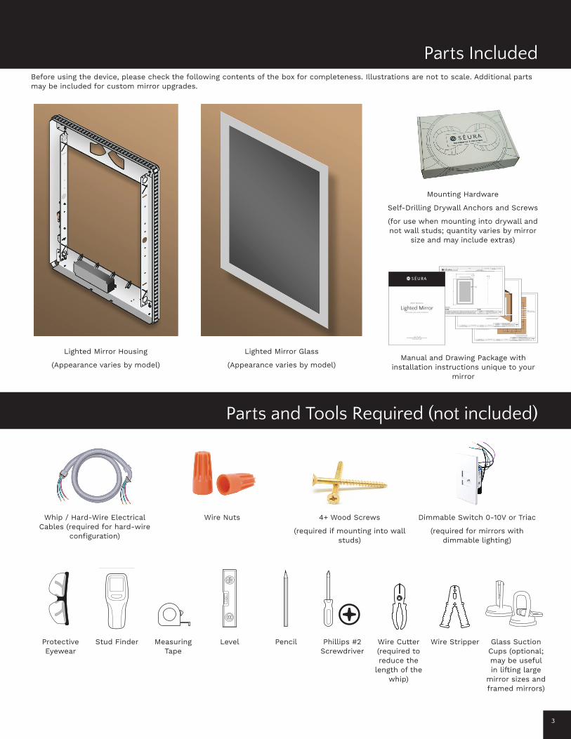
Before using the device, please check the following contents of the box for completeness. Illustrations are not to scale. Additional parts may be included for custom mirror upgrades.
2534"
1214"
OPENTO WALL
19716"
OPENTO WALL
15"
24"
36"
412" 41
2"
412"
534"
578" 57
8"
9916"
7116"
MIRROROUTLINE
WALLSURFACE
0-10V DIMMING CONTROL WIRES(DIMMING CONTROL BY OTHERS)
7/8" KNOCKOUT(0-10V DIMMING WIRES)FIELD WIRING
CONNECTION(HIGH VOLTAGE)
7/8" KNOCKOUT(HIGH VOLTAGE)
INSTALLATION INSTRUCTIONS:
Reference the dimensions from •this sheet to properly locate the keyhole slots on the mounting surface.
If it is not possible to mount to •the wall framing members, use toggle bolts into minimum ½-inch thick drywall.
Make field wiring connections to •the fixture disconnect using the color code listed in the next section.
Hang mirror assembly. Ensure •the brackets are interlocked and mirror is secure.
FIELD WIRING CONNECTIONS:
Accepts AWG 16 - 12 solid or •stranded (19 strands max.)
Strip insulation back .43" to .51"•
Color Code:•
WHITE - neutral BLACK - line voltage GREEN - ground
NOTE: Connect 0-10V dimming signal directly to driver dimming control wires.
-18 OCT 2019Date Created
-Drawing ID Number
S-S-2436-S-AL.7-BLED.4-DModel Number Revised Date
PROPRIETARY AND CONFIDENTIALTHE INFORMATION CONTAINED IN THIS DOCUMENT IS THE SOLE PROPERTY OF THE MANUFACTURER. ANY REPRODUCTION IN PART, OR AS A WHOLE, WITHOUT THE WRITTEN PERMISSION OF MANUFACTURER, IS PROHIBITED.
TOLERANCES(UNLESS OTHERWISE NOTED)
FRACTIONAL: 1/8"ANGULAR: 1.0
TWO PLACE DECIMAL: .03"THREE PLACE DECIMAL: .015"
SHEET3
0-10V DIMMING CONTROL WIRES(DIMMING CONTROL BY OTHERS)
7/8" KNOCKOUT(0-10V DIMMING WIRES)
7/8" KNOCKOUT(HIGH VOLTAGE)
FIELD WIRINGCONNECTION
(HIGH VOLTAGE)
INTERLOCKINGBRACKETS
LED LIGHTING SPECIFICATIONS7.6 W/FT3000K COLOR TEMPERATURE
DIMMABLE DRIVER SPECIFICATIONSINPUT: 120VAC, 50/60HzDIMMING PROTOCOL: 0-10VDIMMING RANGE: 10%-100%(DIMMING CONTROL BY OTHERS)REQUIRES GFCI
-18 OCT 2019Date Created
-Drawing ID Number
S-S-2436-S-AL.7-BLED.4-DModel Number Revised Date
PROPRIETARY AND CONFIDENTIALTHE INFORMATION CONTAINED IN THIS DOCUMENT IS THE SOLE PROPERTY OF THE MANUFACTURER. ANY REPRODUCTION IN PART, OR AS A WHOLE, WITHOUT THE WRITTEN PERMISSION OF MANUFACTURER, IS PROHIBITED.
TOLERANCES(UNLESS OTHERWISE NOTED)
FRACTIONAL: 1/8"ANGULAR: 1.0
TWO PLACE DECIMAL: .03"THREE PLACE DECIMAL: .015"
SHEET2
www.seura.com
PH. 920.857.9069
FAX 920.857.9490
2"
24"
36"
2"
218"
ETCH
1" LIFT-OFF CLEARANCE REQUIRED
Drawing ID Number
Item and Description
Revised DateReseller
SHEET1
DATE:SIGNATURE: NOTE: PLEASE SIGN AND DATE THIS PAGE BEFORE RETURNING TO SEURA, SIGNIFYING YOU AGREE TO ALL SPECIFICATIONS SHOWN ON ALL DRAWING SHEETS. THE BUILD PROCESS WILL NOT BEGIN WITHOUT AN AUTHORIZED SIGNATURE. FOR DRAWINGS THAT REQUIRE REVISIONS, SEND THE REVISIONS TO SEURA NOTED ON THE ORIGINAL DRAWINGS. A REVISED DRAWING PACKAGE WILL BE RE-SENT FOR SIGNATURE.
TOLERANCES(UNLESS OTHERWISE NOTED)
FRACTIONAL: 1/8"ANGULAR: 1.0
TWO PLACE DECIMAL: .03"THREE PLACE DECIMAL: .015"
PROPRIETARY AND CONFIDENTIALTHE INFORMATION CONTAINED IN THIS DOCUMENT IS THE SOLE PROPERTY OF THE MANUFACTURER. ANY REPRODUCTION IN PART, OR AS A WHOLE, WITHOUT THE WRITTEN PERMISSION OF MANUFACTURER, IS PROHIBITED.
-Date Created
- 18 OCT 2019 -
S-S-2436-S-AL.7-BLED.4-D24''(W) X 36''(H) Surface-Mounted Mirror with Allegro Lighted Design and Silver Mirror Glass
UL1598 COMPLIANT
USER MANUAL
1-800-957-38721230 ONTARIO ROAD, GREEN BAY, WI 54311
W W W.SEUR A .COM
PROFESSIONAL INSTALLATION RECOMMENDED
Lighted Mirror
Lighted Mirror Housing
(Appearance varies by model)
Whip / Hard-Wire Electrical Cables (required for hard-wire
configuration)
Protective Eyewear
Measuring Tape
Pencil Wire Stripper
Wire Nuts
Stud Finder Level Wire Cutter (required to reduce the
length of the whip)
Phillips #2 Screwdriver
Glass Suction Cups (optional; may be useful in lifting large
mirror sizes and framed mirrors)
4+ Wood Screws
(required if mounting into wall studs)
Dimmable Switch 0-10V or Triac
(required for mirrors with dimmable lighting)
Lighted Mirror Glass
(Appearance varies by model)Manual and Drawing Package with
installation instructions unique to your mirror
Mounting Hardware
Self-Drilling Drywall Anchors and Screws
(for use when mounting into drywall and not wall studs; quantity varies by mirror
size and may include extras)
Parts Included
3
Wood BitForets à bois
Broca para madera
Stud FinderDétecteur de montant
Detector de vigas
Socket SetJeu de douilles
Juego de carraca
PencilCrayonLápiz
LevelNiveauNivel
DrillPerceuseTaladro
Measuring TapeMétre rubanCinta métrica
Masonry BitForets de maçonnerie
Broca para mampostería
HammerMarteauMartillo
Required ToolsOutils nécessairesHerramientas necesarias
Wood stud wallMur de montant en boisPared de vigas de madera
Concrete wallMur en bétonMuro de concreto
Phillips ScrewdriverTournevis Phillips
Destornillador Phillips
x2 x4x2
x4 x4
A: M6 x 35 mm
x4
B: 14 mm
x4
F: M6 / M8 G: 5 mm
C : M8
x4
E: M8 x 65 mm
Cable Sleeve / Couverture de cable / Cubierta para cable
PDX650W
D: Concrete AnchorAncrages de béton Anclajes para concreto
32"7
8"3
Supplied Parts and HardwarePièces et matériels fournisPiezas y hardware suministrados
1/2”

4
Y”
X”
Mirror Width
MirrorHeight
Installation: Hard-Wired Configuration
Step 2: Map out the installation area and mount the lighted mirror housing to the wall.
• Locate the keyhole slots on the lighted mirror housing. The number of keyhole slots depends on the mirror size. You may refer to the included drawing package for specific dimensions of your mirror and locations of the keyhole slots.
• Using a measuring tape and level, determine where you want to mount the mirror on the wall and mark the keyhole slots with a pencil on the wall. Ensure the mirror is correctly vertically positioned.
• Use a stud finder to determine if the keyhole slots line up with wall studs. We recommend mounting to wall studs if possible.
• Keyhole slots that line up with a stud require a #10 wood screw that is at least 2-inches long.
• Keyhole slots that do not line up with wall studs require the included Self-Drilling Drywall Anchors located in the hardware box. The drywall should be a minimum ½-inch thick. Using a screwdriver, insert the supplied E-Z Anchor Toggles into the corresponding pencil marks on the wall.
• To set the clamp behind the drywall, place the mounting screw into the anchor and push or tap firmly until approximately 1-inch of the screw is protruding (do not rotate).
• Secure the housing to the wall with screws through the keyhole slots.
Step 1: Prepare proper wiring and wall switch.
• Turn off the main power before installing the fixture in order to prevent possible electric shock. Locate the circuit breaker control for the room where you’ll be working and switch the circuit to off.
• A whip is required for hardwire installation. In other words, you need access to a power cable that comes from a Junction Box in the wall. These extra wires are pre-wired together. Make sure the length of the whip is long enough to reach from the power box in the wall to the mirror. If the whip is longer than needed, you may choose to use a wire cutter to reduce the length.
• If your mirror includes dimming capability, verify that your wall switch supports dimming functionality. The dimmable switch must be 0-10V or Triac.
Sample keyhole slot locations are circled in the image above. Check your shop drawing for exact dimensions for your mirror.
IMPORTANT: TURN OFF MAIN POWER TO THE INSTALLATION LOCATION AT THE CIRCUIT BREAKER.

5
Installation: Hard-Wired Configuration (continued)
Step 4: Hang the mirror
• If the mirror has a decorative frame, do not hold the mirror by the frame. For framed mirrors and large mirrors, we recommend using glass suction cups to lift the mirror.
• Once the wire connections are made, make sure all wires are tucked into the wire saddles. This will prevent wires from getting pinched between the mirror and housing.
• Hang the mirror onto the housing by positioning the mounting brackets on the back of the mirror so they rest on top of the brackets on the housing. Start by holding the mirror slightly higher than the housing and slowly lower the mirror until the mirror brackets rest on the housing brackets.
• Ensure the brackets are interlocked and the mirror is secure by making sure the mirror is level and evenly spaced from the wall. Gently try to move the mirror glass. If you can pull any of the four corners away from the housing, then it’s not mounted properly. If the glass moves, it’s likely not fully interlocked and you need to repeat this step to align the mounting brackets.
Step 3: Make wiring connections.
• Séura lighted mirrors are equipped with an easy-to-install wiring fixture disconnect. Connect the whip (extra wires that are pre-wired together) from step 1 to the fixture disconnect located on the mirror housing that is now mounted to the wall. Refer to your included drawing package to identify the location of the fixture disconnect.
• The connection accepts AWG 16 - 12 solid or stranded (19 strands maximum). Using a wire stripper, strip the insulation on the wires back 0.43” to 0.51”. Connect wires into the fixture disconnect using the color code diagram below.
• Connect 0-10V dimming signal directly to the driver dimming control wires.
• Turn the wall switch to on and verify functionality.
Installed Interlocking
Brackets
Wiring connections made by the manufacturer
Field wire connector Connections to be made by the installer in the field
Neutral (White)
Ground (Green)
Line Voltage/Hot (Black) 0-10V Dimming Control Wire (Positive)
0-10V Dimming Control Wire (Negative)
Wiring For Units With 0-10V Dimming
WALL
GLA
SS
LIG
HTE
D M
IRR
OR
HO
US
ING
6
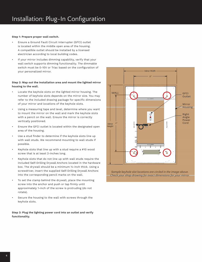
Installation: Plug-In Configuration
Step 1: Prepare proper wall switch.
• Ensure a Ground Fault Circuit Interrupter (GFCI) outlet is located within the middle open area of the housing. A compatible outlet should be installed by a licensed electrician according to local building codes.
• If your mirror includes dimming capability, verify that your wall switch supports dimming functionality. The dimmable switch must be 0-10V or Triac based on the configuration of your personalized mirror.
Step 2: Map out the installation area and mount the lighted mirror housing to the wall.
• Locate the keyhole slots on the lighted mirror housing. The number of keyhole slots depends on the mirror size. You may refer to the included drawing package for specific dimensions of your mirror and locations of the keyhole slots.
• Using a measuring tape and level, determine where you want to mount the mirror on the wall and mark the keyhole slots with a pencil on the wall. Ensure the mirror is correctly vertically positioned.
• Ensure the GFCI outlet is located within the designated open area of the housing.
• Use a stud finder to determine if the keyhole slots line up with wall studs. We recommend mounting to wall studs if possible.
• Keyhole slots that line up with a stud require a #10 wood screw that is at least 2-inches long.
• Keyhole slots that do not line up with wall studs require the included Self-Drilling Drywall Anchors located in the hardware box. The drywall should be a minimum ½-inch thick. Using a screwdriver, insert the supplied Self-Drilling Drywall Anchors into the corresponding pencil marks on the wall.
• To set the clamp behind the drywall, place the mounting screw into the anchor and push or tap firmly until approximately 1-inch of the screw is protruding (do not rotate).
• Secure the housing to the wall with screws through the keyhole slots.
Step 3: Plug the lighting power cord into an outlet and verify functionality.
Y”
X”
Mirror Width
MirrorHeight
Sample keyhole slot locations are circled in the image above. Check your shop drawing for exact dimensions for your mirror.
GFCI Outlet
Right Angle Power Cord
Mirror Housing
WALL
7
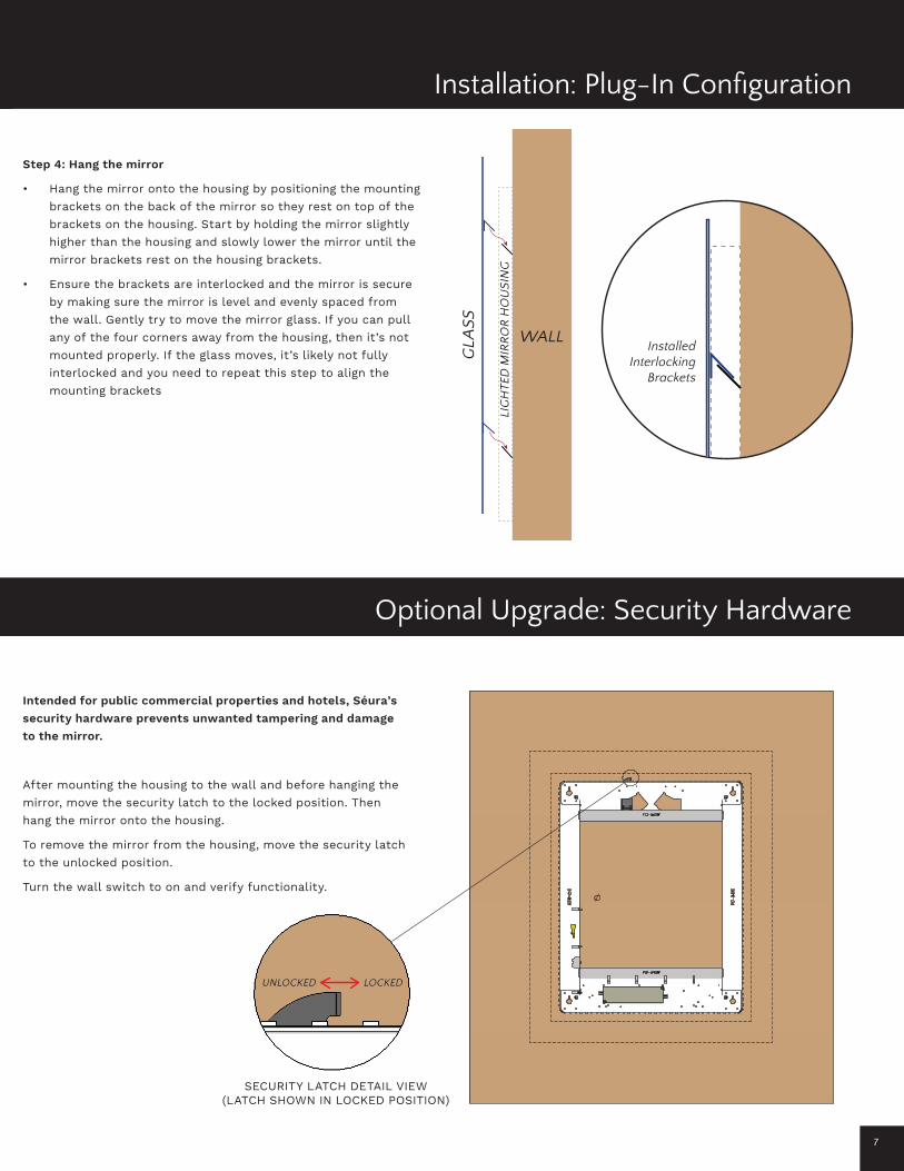
Step 4: Hang the mirror
• Hang the mirror onto the housing by positioning the mounting brackets on the back of the mirror so they rest on top of the brackets on the housing. Start by holding the mirror slightly higher than the housing and slowly lower the mirror until the mirror brackets rest on the housing brackets.
• Ensure the brackets are interlocked and the mirror is secure by making sure the mirror is level and evenly spaced from the wall. Gently try to move the mirror glass. If you can pull any of the four corners away from the housing, then it’s not mounted properly. If the glass moves, it’s likely not fully interlocked and you need to repeat this step to align the mounting brackets
Installed Interlocking
Brackets
GLA
SS
LIG
HTE
D M
IRR
OR
HO
US
ING
WALL
Installation: Plug-In Configuration
Intended for public commercial properties and hotels, Séura’s security hardware prevents unwanted tampering and damage to the mirror.
After mounting the housing to the wall and before hanging the mirror, move the security latch to the locked position. Then hang the mirror onto the housing.
To remove the mirror from the housing, move the security latch to the unlocked position.
Turn the wall switch to on and verify functionality.
UNLOCKED LOCKED
SECURITY LATCH DETAIL VIEW(LATCH SHOWN IN LOCKED POSITION)
Optional Upgrade: Security Hardware
8
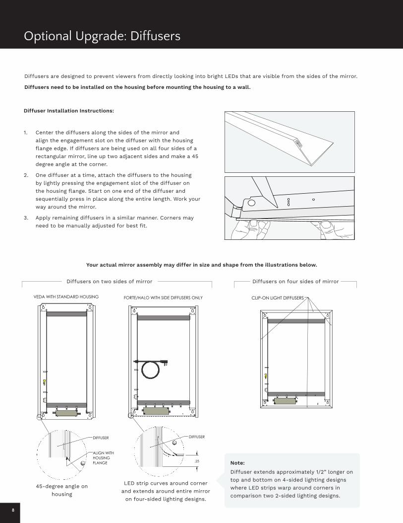
Optional Upgrade: Diffusers
Diffuser Installation Instructions:
1. Center the diffusers along the sides of the mirror and align the engagement slot on the diffuser with the housing flange edge. If diffusers are being used on all four sides of a rectangular mirror, line up two adjacent sides and make a 45 degree angle at the corner.
2. One diffuser at a time, attach the diffusers to the housing by lightly pressing the engagement slot of the diffuser on the housing flange. Start on one end of the diffuser and sequentially press in place along the entire length. Work your way around the mirror.
3. Apply remaining diffusers in a similar manner. Corners may need to be manually adjusted for best fit.
Diffusers are designed to prevent viewers from directly looking into bright LEDs that are visible from the sides of the mirror.
Diffusers need to be installed on the housing before mounting the housing to a wall.
Your actual mirror assembly may differ in size and shape from the illustrations below.
Note:
DIFFUSER DIFFUSER
Diffusers on two sides of mirror
45-degree angle on housing
LED strip curves around corner and extends around entire mirror
on four-sided lighting designs.
Diffuser extends approximately 1/2” longer on top and bottom on 4-sided lighting designs where LED strips warp around corners in comparison two 2-sided lighting designs.
Diffusers on four sides of mirror

9
Optional Upgrade: Diffusers
Improve visibility and keep wet hands off the mirror after a steamy shower with a Séura mirror defogger
Séura’s digital clock discreetly and elegantly displays the time. The internal battery backup prevents clock from powering off and avoids the need for resetting.
Optional Upgrade: Defogger
After mounting the lighted mirror housing and making field wiring connections to the fixture, then it’s time to hard wire the defogger. To do this, bring the mirror close to the housing. There are two wires on the back of the mirror that are on the defogger. Connect the two wires to the neutral and 120 VAC source, it doesn’t matter which wire is connected to which. You will need two wire nuts (one for each wire) to connect to the 120 VAC source.
The clock unit requires it’s own power source and includes a power cord and adapter.
Like the Plug-In Configuration installation instructions on page 6, ensure a GFCI outlet is located within the designated open area of the housing. Plug the clock power cord into the outlet to verify functionality.
After installation, the clock may be programmed using the Séura remote control. Programming instructions can be viewed online at seura.com.
www.seura.com/for-professionals/residential/downloads/
Optional Upgrade: Digital Clock
Copper Free
3000K, Easy to clean
RELIABILITY
CUSTOM CAPABILITY
QUALITY SPEEDSÉURA STYLE
RELIABILITY
CUSTOM CAPABILITY
QUALITY
SPEEDNTP
SÉURA STYLE
SMARTMIRROR
55inch
65inch
84inch
42inch
49inch
CERTIFIED
1000Nit
ComposeEmail CalendarAgenda
7:48
72°
FRIDAY MAY 11
81° 57°
SATURDAY
76° 54°
MONDAY
73° 52°
10%
SUNDAY
68° 48°
Messages News Twitter Instagram Facebook YouTube Podcasts Sports Traffic Pinterest Amazon Tasks

10
Optional Upgrade: Non-Dimmable Nightlight
The nightlight can be wired to your control preference. Choose from having the nightlight always on 24/7, only on when the main lighting is off, or controlled by a separate wall switch or motion sensor.
LED nightlights provide extra light you’ll appreciate during nocturnal trips to the bathroom.
Shared Neural
Ground
Main Lighting Power
Nightlight Power Connection
Nightlight Wiring (For units with Main Lighting & Nightlight only)

11
Séura’s patented mirror glass coatings have been developed to protect the mirror surface and allow easy maintenance.
• The glass surface should be cleaned with any conventional non-ammoniated glass cleaner. Care should be taken to use only a soft lint-free cloth. Apply all cleaners directly to the cloth and not the mirror surface. Never saturate the mirror surface as residual cleaner may seep behind the mirror.
• Stubborn spots can be removed with solvents such as mineral spirits, de-natured alcohol, and acetone. Immediately remove solvent and dirt residues per the prescribed methods above with a compatible glass cleaner or water.
Decorative frames should be cleaned using a clean, soft cloth to wipe dust and dirt off.
The standard limited warranty policies of Séura, Inc. (“Séura”) shall apply to all equipment or other goods (“Products”) at the time of sale to any authorized Séura distributor and/or product reseller. These warranty policies may be modified by Séura from time to time. Copies of the standard limited warranties then in effect for a particular Product will be made available upon request and are also available on the Séura website at https://www.seura.com/warranty/. This warranty is valid only with respect to Product sales in the U.S. and Canada.
If any Product fails to work or operate properly because of a defect in materials or workmanship, Séura will, if notified of such defect within the applicable warranty period indicated below, at its option, either: (a) repair the Product with new or refurbished parts onsite or at Séura’s factory, including Séura’s labor if applicable; or (b) replace the Product with a new or refurbished Product; or (c) if repair or replacement is not commercially feasible, refund an amount equal to a pro rata share of the current MSRP (as determined by the remainder of the warranty period). The remedy chosen will be in good faith and at the discretion of Séura. In no event will Séura be responsible for any costs related to installation and/or removal of Product.
Séura warrants its Products as set forth below, which warranty periods shall start and run from the date of Séura’s sale of the Product:
• Lighted Mirrors (excluding Select Lighted Mirrors) with respect to Séura’s labor, glass, structure, and assembly for seven (7) years; electrical and LED light strips for five (5) years. Mirror technology with respect to Séura’s labor and parts including wireless music technology, clocks, nightlights, defoggers, dimmers, and voice technology (microphone, voice indicator LED strip, and speakers) are covered for two (2) years.
• Select Lighted Mirrors with respect to Séura’s labor, glass, structure, and assembly for one (1) year; electrical and LED light strips for three (3) years.
• Lighted TV Mirrors with respect to Séura’s labor, glass, structure, and assembly for three (3) years; electrical and LED light strips for five (5) years. TV including remote and power supply for two (2) years.
• Decorative Frames for one (1) year.
Exceptions to Warranty: This warranty is valid only with respect to Product sales in the U.S. and Canada. Séura does not warrant Products against defects arising out of, related to, or caused by, whether totally or partially, and whether directly or indirectly, any of the following:
A. Failing to properly clean and maintain, any Product, part or component of a Product, including, but not limited to, filters, front bezel, and other Product areas or components;
B. A Product’s extended use, including particularly, commercial applications, where a Product is operating on average more than twelve (12) hours per day on a permanent or extended periodic basis;
C. Circumstances, damage (including concealed damage) or other conditions occurring during shipment of a Product or at any time after a Product leaves Séura’s facility (including without limitation transport of the Product to or from Séura before or after authorized service). Products must be packed properly using original packaging or Séura replacement or pre-authorized packaging. Customer assumes all risk, and costs, including transportation costs, while Product is in transit to or from Séura;
D. Circumstances, damage or other conditions occurring during unpacking and/or removal of a Product from its original packaging, including the removal of protective material;
E. Improper, incorrect, or insufficient AC supply voltage to a Product;
F. Alterations, modifications, including use of unauthorized mount, or changes to a Product without Séura’s prior written authorization;
G. The incorporation of a Product into or within a product of a third party, without Séura’s prior written authorization;
H. A Product’s misuse, neglect use, abuse, or improper operation, including the failure to follow a Product’s normal and ordinary operating instructions;
I. The effects of fire, flood, lightning, electrical surges, water and other liquid infiltration, smoke, insect or animal infestation, sand, mud, chemicals, improper cleaning agents and other substances not intended to come into contact with a Product, including any such substances contact with a Product as the result of acts of God;
J. The improper or faulty installation, setup, or adjustment of a Product;
K. A Product’s repair, attempted repair, or total or partial disassembly by any party other than a Séura authorized service representative;
L. When the Product occurs with pixel errors within the specified and permitted area. (For more information about this, inquire directly with Séura regarding the Séura Pixel Policy.)
M. Corrosion that does not affect the performance of a Product or the reasonable cosmetic appearance of a Product (including without limitation, scratches or other paint or finish damage to a Product that lead to or are caused by, in part or in total, corrosion);
N. When a Lighted Mirror or Lighted TV Mirror using LEDs retains an overall brightness greater than 70% of the original brightness, including cases whereas an individual LED fails; and/or
O. Normal wear and tear on the Product.
Séura does not warrant that its Products will integrate with any third party products at present or in the future. It is purchaser’s responsibility to test and verify compatibility. Further, Séura does not warrant its software or programs, or any content downloaded after shipment. It is the purchaser responsibility to take precautions to protect the product from malware, viruses, data loss, and other potentially destructive programs.
Warranty Disqualifiers. This Limited Warranty only extends to, and runs for the benefit of, the original purchaser of the Product and only covers a Product purchased new. All warranty claims must be submitted together with original proof of purchase and any Product subject to a warranty claim must retain its original Séura serial number. Séura reserves the right to require any warranty claimant to produce the original purchase receipt or other original purchase date proof as may be reasonably required by Séura to verify the Product’s warranty eligibility. Séura shall have no liability with respect to Products whose serial number has been removed, defaced, replaced, or otherwise tampered with in any manner. Séura reserves the right to examine all failed product components and determine, in its sole discretion, whether any product components are defective and covered under warranty.
LIMITATION OF LIABILITY. THE EXPRESS LIMITED WARRANTIES SET FORTH HEREIN ARE IN LIEU OF ALL OTHER WARRANTIES, WRITTEN OR ORAL, EXPRESSED OR IMPLIED, INCLUDING, BUT NOT LIMITED TO, ANY IMPLIED WARRANTIES OF MERCHANTABILITY OR FITNESS FOR A PARTICULAR PURPOSE OR USE. SÉURA WILL NOT BE LIABLE FOR ANY DAMAGE TO OTHER PROPERTY CAUSED BY ANY DEFECT IN THE PRODUCT, DAMAGES BASED ON INCONVENIENCE, LOSS OF BUSINESS OPPORTUNITY, LOSS OF GOODWILL, INTERFERENCE WITH BUSINESS RELATIONSHIPS, OR OTHER COMMERCIAL LOSS, EVEN IF THE CUSTOMER HAS BEEN ADVISED OF THE POSSIBILITY OF SUCH DAMAGES. SÉURA WILL NOT BE LIABLE FOR ANY LOSS, DAMAGE OR LIABILITY OR ANY DIRECT, INCIDENTAL, INDIRECT, PUNITIVE, SPECIAL OR CONSEQUENTIAL DAMAGES RESULTING FROM THE USE OR MISUSE OF A PRODUCT, OR ARISING OUT OF ANY BREACH, BY THE PURCHASER OF A PRODUCT, OF THIS LIMITED WARRANTY. SÉURA SHALL NOT BE LIABLE FOR ANY CLAIM AGAINST THE CUSTOMER BY ANY OTHER PARTY. SÉURA SHALL NOT BE LIABLE FOR ANY VERBAL WARRANTY ASSURANCES MADE BY ANY EMPLOYEE OR AUTHORIZED DISTRIBUTOR, RESELLER OR INSTALLER THAT CONFLICTS WITH OR ENHANCES THE WRITTEN WARRANTY HEREIN. SOME STATES DO NOT ALLOW THE EXCLUSION OR LIMITATION OF INCIDENTAL OR CONSEQUENTIAL DAMAGES, OR LIMITATIONS ON HOW LONG AN IMPLIED LIMITED WARRANTY LASTS, SO THE EXCLUSIONS MAY NOT APPLY TO A PARTICULAR PURCHASER. NOTWITHSTANDING ANYTHING HEREIN TO THE CONTRARY, SÉURA’S MAXIMUM AGGREGATE LIABILITY RELATED TO ANY WARRANTY CLAIM OR WITH RESPECT TO A PRODUCT SHALL NOT EXCEED THE THEN CURRENT SÉURA WHOLESALE PRICE OF THE SPECIFIC PRODUCT FROM WHICH THE CLAIM DERIVES.
NOTICE OF ANY WARRANTY CLAIM MUST BE RECEIVED BY SÉURA, IN WRITING, PRIOR TO THE EXPIRATION OF THE APPLICABLE WARRANTY PERIOD SET FORTH ABOVE. THE PRODUCT WARRANTY APPLIES ONLY FOR THE PERIODS SET FORTH ABOVE.
Warranty Procedure. A warranty claimant must contact Séura at 920-857-9069 for a diagnostic. Please have your Product receipt available. At that time, Séura will provide technical support over the phone to attempt to fix the problem. If unsuccessful, a Séura Representative will determine if the Product will be serviced onsite, replaced, or returned to Séura’s factory in Green Bay, Wisconsin for repair. If Séura determines that the Product is not covered under the warranty or damaged in shipping, Séura will notify and inform the purchaser of service alternatives that are available on a fee basis.
Toll-Free Technical Support: Please call 1-800-957-3872 to speak with a Séura Technical Support Representative. Séura Representatives are available Monday-Friday, 8:00am-4:30pm Central Time.
Onsite Service: If Technical Support determines the problem may be fixed onsite, a Séura service agent will be scheduled within 24 hours to service the unit. A Séura representative will work with the customer to schedule a convenient time for onsite service. Parts may be sent to the customer’s location. Onsite service is available in the United States during normal business hours Monday – Friday, unless other special circumstances exist and special arrangements are made.
Factory Service: If Technical Support determines the Product must be sent back to Séura’s factory for repair, the customer must follow return instructions below. Séura will ship the repaired Product to the authorized reseller, installer or customer’s address. This warranty does not cover removal or installation costs of Products.
Advanced Replacement: If Technical Support determines the Product must be replaced, Séura will ship a new Product to the authorized reseller, installer or customer’s address. The customer must follow return instructions below to send the damaged Product back to Séura’s factory. Credit card information will be collected before shipment of the replacement Product. If Séura does not receive the original Product back within thirty (30) days of shipping the replacement Product, the credit card on file will be charged at full MSRP. This warranty does not cover removal or installation costs of Products.
Return Instructions: If return is necessary, Séura will issue a return goods authorization (RGA) number and, if applicable, specific return and shipping instructions. A Product will only be accepted for warranty claims if returned and shipped to Séura in the Product’s original packaging materials. If original packaging is not available, please contact Séura to receive authorized replacement packaging. Packages not bearing the issued returned goods authorization (RGA) number will not be accepted by Séura and will be returned to sender. In addition to the Product, the package must include the warranty claimant’s original sales receipt for the purchase of the Product. All Product returns shall be received by Séura, at 1230 Ontario Road; Green Bay, WI 54311 with freight prepaid by the warranty claimant. Séura shall not be responsible for, and the warranty claimant assumes and retains all such responsibility, any damage or loss to or of the Product during shipment to and from Séura as the result of a warranty claim.
Exclusive Remedy. This Limited Warranty sets forth the exclusive remedies of a warranty claimant, and the exclusive liabilities and obligations of Séura, with respect to allegations of a defective Product.
19163121.3
Care and Maintenance
Copper Free
3000K, Easy to clean
RELIABILITY
CUSTOM CAPABILITY
QUALITY SPEEDSÉURA STYLE
RELIABILITY
CUSTOM CAPABILITY
QUALITY
SPEEDNTP
SÉURA STYLE
SMARTMIRROR
55inch
65inch
84inch
42inch
49inch
CERTIFIED
1000Nit
ComposeEmail CalendarAgenda
7:48
72°
FRIDAY MAY 11
81° 57°
SATURDAY
76° 54°
MONDAY
73° 52°
10%
SUNDAY
68° 48°
Messages News Twitter Instagram Facebook YouTube Podcasts Sports Traffic Pinterest Amazon Tasks
Warranty
Publish date: February 1, 2020Information is subject to change without notice.
© 2020 Séura
1230 Ontario Road, Green Bay, Wisconsin 543111-800-957-3872 [email protected]
94-000002
For additional technical support, please contact Séura at 1-800-957-3872 during regular business hours: M-F 8:00am - 4:30pm, Central Time.