user manual fdg series...vfd abb acs550-u1-038a-4 1 damper actuator johnson controls m9203-gga-rk 2...
TRANSCRIPT

Nyle Systems
Nyle Systems
12 Stevens Road
Brewer, ME, 04412
www.nyle.com
800-777-6973
User ManualFDG Series

2
Table of Contents Specifications ................................................................................................................................................ 3
Conventional Batch Dryer Theory of Operation .......................................................................................... 4
Dryer Loading Preparation............................................................................................................................ 5
Pre Load Check .......................................................................................................................................... 5
Startup Check ............................................................................................................................................ 5
Dryer Unloading Preparation ....................................................................................................................... 5
Controls Operation........................................................................................................................................ 6
Sensor Definitions ..................................................................................................................................... 6
Control Screen Navigation ........................................................................................................................ 7
Control Screen Definitions ........................................................................................................................ 8
Home Screen ......................................................................................................................................... 8
Information Screen ............................................................................................................................... 9
Equipment Screen ............................................................................................................................... 11
Diagnostics Screen .............................................................................................................................. 11
Schedule Screen .................................................................................................................................. 12
Trend Screen........................................................................................................................................ 13
Alarm Screen ....................................................................................................................................... 14
Schedule Load/Save Screen ................................................................................................................ 14
Value Entry Screen .............................................................................................................................. 15
Powering Up the Dryer ........................................................................................................................... 16
Starting Dryer Equipment ....................................................................................................................... 16
Schedule Management ........................................................................................................................... 16
Schedule Monitoring ........................................................................................................................... 17
Loading or Saving a Schedule ............................................................................................................. 17
Data Logging ............................................................................................................................................ 18
Remote Monitoring ................................................................................................................................. 18
Safeties .................................................................................................................................................... 19
Maintenance ............................................................................................................................................... 19
APPENDICES/NOTES .................................................................................................................................... 21
3
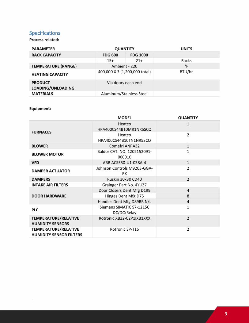
Specifications Process related:
PARAMETER QUANTITY UNITS
RACK CAPACITY FDG 600 FDG 1000 15+ 21+ Racks TEMPERATURE (RANGE) Ambient - 220 °F
HEATING CAPACITY 400,000 X 3 (1,200,000 total) BTU/hr
PRODUCT LOADING/UNLOADING
Via doors each end
MATERIALS Aluminum/Stainless Steel
Equipment:
MODEL QUANTITY
FURNACES
Heatco HPA400CS44B10MR1NR5SCQ
1
Heatco HPA400CS44B10TN1NR5SCQ
2
BLOWER Comefri ANPA32 1
BLOWER MOTOR Baldor CAT. NO. 1202152091-
000010 1
VFD ABB ACS550-U1-038A-4 1
DAMPER ACTUATOR Johnson Controls M9203-GGA-
RK 2
DAMPERS Ruskin 30x30 CD40 2 INTAKE AIR FILTERS Grainger Part No. 4YUZ7
DOOR HARDWARE Door Closers Dent Mfg D199 4
Hinges Dent Mfg D75 8 Handles Dent Mfg D89BR N/L 4
PLC Siemens SIMATIC S7-1215C
DC/DC/Relay 1
TEMPERATURE/RELATIVE HUMIDITY SENSORS
Rotronic XB32-C2P1IXB1XXX 2
TEMPERATURE/RELATIVE HUMIDITY SENSOR FILTERS
Rotronic SP-T15 2

4
Conventional Batch Dryer Theory of Operation The FDG Series are a batch load product dryers designed to operate by introducing a loaded product to
heat and air flow for the purpose of removing moisture from the product. By controlling the temperature
and velocity of the air travelling through the product load and the degree of exhausted air, drying
characteristics may be modified according to the operator’s needs.
Air flow through the product load is from the blower end to the exhaust end of the chamber. Therefore
the blower end of the product load is known as the “air on” side, while the exhaust end of the product
load is known as the “air off” side. Nominally, the air on side may be called the loading side and the air off
side the unloading side, but in practice the direction of loading is immaterial.
As air travels through the load, moisture is released by the product and absorbed into the air. The more
moisture that is absorbed, the less the passing air is able to absorb moisture. At some point within the
product load, the air may become saturated and will be unable to absorb further moisture. Because of
this, a horizontal cross section of the product load during a drying cycle would reveal variation in moisture
content from dry on the air on side to wet on the air off side, with a travelling layer or “zone” of drying
within the load. This “drying zone” will move in the direction of air flow as the product load dries, until
eventually the full load will equalize and relatively small moisture variation will exist.
The drying process described is measurable by monitoring of air conditions on both sides of the bulk
product load. Air on values of temperature and relative humidity may be compared with air off values to
determine what is occurring within the load. In the midst of a drying process, the air on temperature will
be higher than the air off temperature, and the air on humidity will be lower than the air off humidity.
Most efficient use of the blower moving air through the product would be such that the air off humidity
is nearly saturated during the drying process.

5
Installation Instructions Make sure that all seams and gaps are properly closed with NSF certified Gaskets or NSF
certified Silicone Caulking.
Make sure that unit is sealed to the floor using NSF certified Gaskets or NSF certified Silicone
caulking.
Ensure that control panel set-up is mounted on side of the unit in such a way that it is easily
cleanable manually.
Dryer Loading Preparation
Pre Load Check Conduct the following checks prior to loading the drying chamber.
Chamber is free of foreign material which may be sucked into the furnace and blower intake on
the exhaust end of the chamber.
Chamber air intake is free of foreign material on expanded metal surface.
Blower exhaust (immediately inside and above loading doors) is free of foreign material on
expanded metal surface.
Gas supply for furnaces is on.
Air on and air off temperature/RH sensors are reading approximately ambient temperature/RH.
Ensure prior to beginning drying cycle that personnel are clear from drying chamber.
Startup Check Once the chamber is loaded with product and the blower and furnace are running, conduct the following
checks.
Air intake filter is not indicating a dirty intake filter.
Air on temperature/RH sensor is reading higher temperature and lower RH than air off
temperature/RH sensor.
PLC is free of alarms.
Schedule is on if desired.
Dryer Unloading Preparation Prior to unloading the drying chamber, conduct the following checks.
Ensure that the dryer is sufficiently cool to avoid any burn hazard to personnel who will be working
inside the chamber.
Ensure that the drying cycle is complete, with furnaces and blower off.

6
Controls Operation The FDG Series dryers are equipped with a controls package allowing manual and automatic control of
system components, and manual or scheduled control of drying conditions.
Sensor Definitions Dryer conditions monitored by the controls package during operation include:
PARAMETER DESCRIPTION SENSOR
AIR ON TEMPERATURE
Measures the temperature of the air prior to entering the product load. The air on temperature sensor is located downstream of the furnace and blower and upstream of the product load. This value is measured and compared with the user set point “Temp” and used to modulate the furnace output. This value is viewable on the Home Screen, on the Information Screen, and on the Trend
Screen.
Rotronic XB32-
C2P1IXB1XXX
AIR ON RH Measures the relative humidity of the air prior to entering the product load. The air on RH sensor is located downstream of the furnace and blower and upstream of the product load. This value
is viewable on the Information Screen. AIR OFF TEMPERATURE
Measures the temperature of the air leaving the product load. The air off temperature sensor is located downstream of the product
load and upstream of the furnace and blower. This value is viewable on the Information Screen and on the Trend Screen.
Rotronic XB32-
C2P1IXB1XXX
AIR OFF RH Measures the relative humidity of the air leaving the product load. The air off RH sensor is located downstream of the product load and upstream of the furnace and blower. This value is measured
and compared with the user set point “RH” on the Schedule Screen and used to advance the schedule in RH step mode. Please
refer to the schedule management portion of the manual for further information. This value is viewable on the Information
Screen and Trend Screen. EXHAUST PERCENTAGE
Measures the percentage that the exhaust/intake dampers are open. This value is viewable on the home screen.
Johnson Controls Actuator Feedback

7
Control Screen Navigation

8
Control Screen Definitions
Home Screen
The home screen provides basic process information, including:
A comparison between dryer readings and set point values for drying parameters; equipment status;
navigational buttons for further controls functionality; start/Stop buttons for the dryer.
Definitions:
“Heat” light: Indicates whether the furnace call is active. A green light indicates that the furnace call is
active. A blank or white light indicates that the furnace call is not active.
“Blower” light: Indicates whether the blower call is active. A green light indicates that the blower call is
active. A blank or white light indicates that the blower call is not active.
“Vent” light: Indicate that feedback is being received from the exhaust damper. A green light indicates
that feedback is being received, while a blank or white light indicates that feedback is not being received.
Readings/Set Points Window:
READINGS SETPOINTS
TEMP: Current air on temperature User set point for air on temperature EXHAUST: Current percentage exhaust damper is open User set point for exhaust percentage BLOWER: Current percent of maximum blower speed User set point for percentage of full
blower capacity

9
“Trend” button: Changes the display to the Trend Screen.
“Schedule” button: Changes the display to the Schedule Screen.
“Equipment” button: Changes the display to the Equipment Screen.
“Information” button: Changes the display to the Information Screen.
Information Screen
The information screen provides process temperature and relative humidity information from each of the
two Temp/RH sensors. The information screen also allows the user to reach the Diagnostics Screen.
RH/Temp Window:
RH TEMP
AIR ON Current air on relative humidity value
Current air on temperature value
AIR OFF Current air off relative humidity value
Current air off temperature value
10
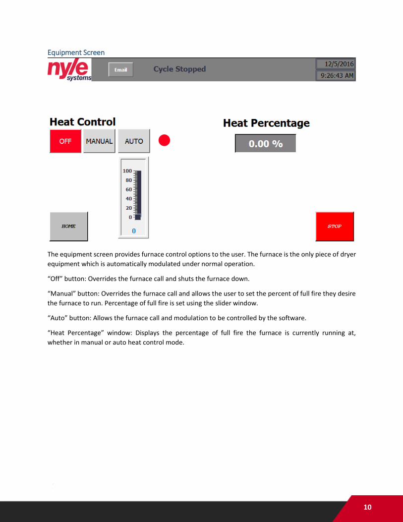
Equipment Screen
The equipment screen provides furnace control options to the user. The furnace is the only piece of dryer
equipment which is automatically modulated under normal operation.
“Off” button: Overrides the furnace call and shuts the furnace down.
“Manual” button: Overrides the furnace call and allows the user to set the percent of full fire they desire
the furnace to run. Percentage of full fire is set using the slider window.
“Auto” button: Allows the furnace call and modulation to be controlled by the software.
“Heat Percentage” window: Displays the percentage of full fire the furnace is currently running at,
whether in manual or auto heat control mode.

11
Diagnostics Screen
The diagnostics screen provides information useful for PLC and equipment troubleshooting purposes.
During troubleshooting, a Nyle technician may request information displayed on this screen.
“Temp and RH” column:
Readings from each of the combination temperature/relative humidity sensors are displayed here.
“Comms Status” column:
This information indicates the communications status of the PLC with the blower variable frequency drive
(VFD).
“Inputs” column:
The various inputs to the PLC are indicated.
“0.0”: EStop: A “False” reading indicates that the emergency stop is pressed. A “True” reading indicates
that the emergency stop is not pressed.
“0.1” through “0.4”: Burner Fault: A “False” reading indicates that the burner stage wired to that input is
in a fault condition. A “True” reading indicates that the burner stage wired to that input is not in a fault
condition.
“Outputs” column:
The various outputs from the PLC to dryer equipment are indicated.

12
“Heat”: A “True” reading indicates that the PLC is calling for the furnace to run. A “False” reading indicates
that the PLC is not calling for the furnace to run.
“Blower”: A “True” reading indicates that the PLC is calling for the blower to run. A “False” reading
indicates that the PLC is not calling for the blower to run.
Schedule Screen
The schedule screen allows the user to manage dryer scheduling. Further details concerning schedule
operation are included in the schedule management portion of the manual.
“Step” column: Identifies the step number.
“Step Mode” column: Indicates the type of step mode selected for the particular step number.
“Time” column: Indicates the run time in minutes selected for a “Time” step mode.
“Temp” column: Indicates the temperature setpoint selected for each step number.
“RH” column: Indicates the relative humidity setpoint selected for an “RH” step mode.
“Exhaust” column: Indicates the percentage of full exhaust (100%) selected for each step number.
“Blower” column: Indicates the percentage of full speed (100%) selected for each step number.
“Schedule: ON/OFF” button: Activates or deactivates the current schedule.

13
Trend Screen
The trend screen allows the user to view the previous 24 hours of dryer operation in a graphical display.
The horizontal axis denotes time and date that a data point was recorded. The left vertical axis serves as
a scale for the logged temperature information. The right vertical axis serves as a scale for the logged
relative humidity information.
Logged parameters include “Air On Temp,” “Air Off Temp,” “Air Off RH,” and “Temp Setpoint.”

14
Alarm Screen
The alarm screen allows the user to view currently active alarm conditions. The alarm number will
correspond with a code produced by the blower VFD and found in the VFD manual.
Schedule Load/Save Screen

15
The schedule load/save screen allows the user to save a currently programmed schedule or load a
previously saved schedule. Further details concerning this screen are included in the schedule
management portion of the manual.
Value Entry Screen
The value entry screen appears when the user taps a set point value window, and allows the user to type
a numerical value into the set point window. Cursor navigation keys are included in the lower right corner
of this screen.
16
Powering Up the Dryer Before providing power to the dryer:
Ensure that blower and furnace service panels are in place;
Ensure that electrical service panels are in place;
Ensure that gas line shutoff valves are open.
Once powered up, the controls screen will go through a boot process prior to the home screen being
displayed.
Starting Dryer Equipment Without entering a schedule, the dryer equipment may be operated in a manual fashion from the home
screen. After the dryer is powered up, conduct the following steps:
1. From the home screen, tap any one of the three windows under the “Setpoints” column.
2. The value entry screen will appear. Enter a value and tap the return or enter button.
3. Repeat step 2 for “Temp,” “Exhaust,” and “Blower” setpoints.
4. Tap the “Start” button.
The blower and damper actuators will immediately begin to operate according to the setpoints entered.
The furnace will enter a startup sequence, including a purge mode, before firing and operating according
to the temperature setpoint entered.
Schedule Management In order to operate a drying schedule, use the schedule management features included with the controls
package. From the home screen, tap the schedule button along the bottom of the screen. Up to 10
schedule steps may be programmed into the schedule by using the “+” and “-“buttons on the bottom of
the schedule screen.
Schedule flexibility is provided primarily by allowing the user to select from 4 “step modes,” including
Time, Temp, RH, and Cool Down. Each of the step modes uses different criteria to determine when to
advance to the following step within the schedule. Each step mode operates as follows:
Time step mode: A time step allows the user to input a set amount of time in minutes that the step should
run for before advancing to the following step. Setpoints available for user input during a time step include
Temp, Exhaust, and Blower. RH is allowed to vary. NOTE: Do not adjust the time setpoint of a currently
active time step. Doing so will cause the current time step to reset or advance to the next step.
Temp step mode: A temperature step allows the user to input a temperature value that the dryer should
warm up to before advancing to the following step. Setpoints available for user input during a temp step
include Temp, Exhaust, and Blower. RH is allowed to vary.
RH step mode: A relative humidity step allows the user to input a relative humidity value that the dryer
should dry down to before advancing to the following step. Setpoints available for user input during an
RH step include Temp, RH, Exhaust, and Blower.
Cool Down step mode: A cool down step allows the user to end a cycle by venting heat from the dryer
with no furnace input, and should not be used as an intermediate step (to prevent furnace cycling). The

17
only setpoint available for user input during a cool down step is the blower speed percentage. During a
cool down step, the exhaust percentage defaults to 100%, and temp and RH are allowed to vary. A cool
down mode ends the cycle when air on temperature is measured to be equal to the setpoint user specified
in the load/save schedule screen.
Note that for all of the step modes except for time, the schedule will advance based upon a selected dryer
parameter other than time. Therefore, experimentation will be necessary to understand the amount of
time a particular schedule will take to run to completion. Factors affecting the run time of a particular
schedule include product type, product load size, and ambient air conditions.
To enter and run a new schedule, conduct the following steps:
1. From the home screen, tap the schedule button along the bottom of the screen.
2. Using the “+” and “-“buttons along the bottom of the screen, adjust the number of steps desired
for the schedule.
3. For the first step, tap the step mode window and select a step mode from the drop down menu.
4. Depending upon the step mode selected, continue to the right across the screen until each
selectable parameter has been entered for the particular step.
5. Repeat steps 3 and 4 for each step.
6. Return to the home screen.
7. Tap the start button. The dryer will start up based upon the values displayed on the home screen.
8. Return to the schedule screen.
9. Tap the “Schedule: OFF” button in the lower right corner of the schedule screen to activate the
schedule. It should then read “Schedule: ON.” The dryer should now begin with step 1 of the
entered schedule.
Schedule Monitoring While a schedule is running, the schedule screen will provide indication of which step is being run, and
whether or not a transition is being considered. While a particular step is active, the step number will be
highlighted green. If a condition has been met and is counting down toward advancing to the following
step, the current step will flash. When the condition has been met for enough time to filter out sensor
flutter, the next step will be highlighted green and dryer equipment will follow the entered conditions for
the highlighted step.
Loading or Saving a Schedule As long as an SD card is inserted into the appropriate slot in the back of the control screen (accessed by
opening the control panel door), schedules may be saved to or loaded from the SD card from the control
schedule load/save screen.
To load or save a schedule, conduct the following steps:
1. From the schedule screen, tap the load/save button to enter the load/save dialog. If a saved
schedule is loaded, the “Current Schedule” window will show a numerical value corresponding to
a previously saved schedule. Otherwise, the “Current Schedule” window will be empty.
2. Tap the load/save value entry window, and enter a number in the value entry screen. Tap the
return or enter button.

18
3. Tap the load or save buttons to either load the entered schedule or save the entered schedule to
the selected number slot.
4. Tap the “Schedule Center” button to return to the schedule screen.
Data Logging As long as an SD card is inserted into the appropriate slot in the back of the control screen (accessed by
opening the control panel door), operational data may be logged. Data logging functionality is active
when:
1. An SD card is present AND
2. A cycle is active.
No further user action is necessary to activate data logging as long as the above conditions are met. Data
is logged at a frequency of 1 measurement per minute.
Data is logged to a folder named “NyleDataLogs” on the inserted SD card. If a new SD card is inserted, the
folder will be automatically created by the software.
In order to retrieve or otherwise manage data, do not remove the SD card from the HMI slot. Data
management may be accomplished from a computer web browser using the following steps:
1. Enter the IP address of your dryer PLC into the web browser address bar. The dryer IP address is:
192.168.1.61
2. Click on the “ENTER” button at the top left of the page.
3. Sign in with the following information:
a. Name: Administrator
b. Password: 100
4. Press Enter on your keyboard or click on the “Log in” button at the bottom right of the log in
context box to enter the PLC management screen.
5. On the left side of the page, locate and select the following: File Browser SD Card Nyle Data
Logs
6. You should see data logs collected during previous cycles and named: “Nyle_[schedulename]”
7. Use the file operations to the right of the file name to download, download and clear, or delete
data logs from the SD card.
Remote Monitoring With a customer provided Ethernet connection to the dryer PLC and installation of a VNC client on a
customer provided device (PC or smart phone), remote monitoring and control are possible. When
prompted by the VNC client, enter the following:
IP Address: 192.168.1.61
Password: 100
The HMI screen should appear as it does at the local control box. Using the mouse pointer, buttons may
be pressed and values adjusted from this display.

19
Safeties Safety Setpoint Action Reset
Dryer Over Temperature
250°F Shut Down Furnace, HMI Alarm, Text Alarm
Auto-reset
Emergency Stop Control panel button pressed
Shut Down Furnace/Blower, HMI
Alarm
Twist Out E-Stop (Schedule
continues to run) Low Air Flow Blower RPM < 400 Shut Down Furnace, HMI
Alarm, Text Alarm Auto-reset
Burner Over Temperature
250°F Shut Down Furnace, HMI Alarm, Text Alarm
Manual Button Press
VFD Fault N/A Furnace Shutdown, HMI Alarm, Text Alarm
Auto-reset Code 28, all other codes manual reset at
HMI Dryer Temperature Setpoint Drift
>+/-5°F for 15 minutes Text Alarm No Reset
Vent/Damper Fault Compare exhaust setpoint with feedback
HMI Alarm Investigate and Repair
Maintenance The following maintenance recommendations are provided based upon an operating schedule including
6 days of operation per week. These items should also be checked regardless of previous inspection after
any lengthy period of inactivity.
Component Interval Action Appendix
FURNACE Each Load Inspect combustion air opening for dirt/debris. Inspect vent stack for deterioration. Inspect
condensate drains to ensure lack of blockages.
A
Annually The duct furnace should be inspected by a qualified service agency. The condition of the burners, heat exchanger, draft inducer, vent system, operating
controls and wiring should be determined. Check for obvious signs of deterioration, accumulation of dirt and debris and any heat or water related damage.
Any damaged or deteriorated parts should be replaced before the unit is put back into service. A
combustion analysis should be completed to be sure that the system is performing normally.
A
BLOWER Annually Inspect fan intake to ensure lack of dirt and debris. B
Ensure that bolts are tight.

20
BLOWER MOTOR
As Necessary Preventative maintenance is not necessary for the blower motor. VFD feedback concerning motor
operation will warn of motor problems.
B, F
DAMPER ACTUATORS
Annually Inspect damper actuator positions at 0% and 100% exhaust to ensure full range of motion.
C
INTAKE AIR FILTERS
Monthly Inspect intake air filters to ensure they are free of debris. Dirty air filter will warn that filters need to be
replaced based upon static pressure drop across filter.
D
TEMP/RH SENSOR FILTERS
Annually Inspect sensor filters for corrosion, discoloration, or clogging, and replace if necessary.
E
DOOR GASKETING
Quarterly Recommend NSF approved gasketing around and between loading and unloading doors to ensure lack
of gaps. Replace as necessary.
N/A
CHAMBER SEALANT
Quarterly Recommend NSF approved sealant between chamber panels and between chamber and floor. Add or
replace as necessary.
N/A

21
APPENDICES/NOTES