user manual ets diagnosis display - ims limited...user manual ets diagnosis display for software...
TRANSCRIPT
User manual ETS diagnosis display
For software version V1
P/N: A07954.0.03.A.EN
Dynamic System Control
Intelligent steering and suspension
www.v-s-e.nl

Electronic Truck/Trailer Steering - Apr, 2009
User Manual ETS diagnosis display
P/N: A07954.0.03.A. EN
Copyright © V.S.E. Vehicle Systems Engineering B.V. – Veenendaal, The Netherlands – www.v-s-e.nlAll rights are reserved. Reproduction in whole or in part is prohibited without the written consent of the copyright owner.
2
Revision
Nr Date Author Approved Modification00 19-09-2007 R. Nijholt R. de Zaaijer First release (only in english)01 21-11-2008 R. Nijholt Dirk Inia Software update display V11002 03-04-2009 R. Nijholt Dirk Inia Software update display V120
References
VSE part number Descriptionxxx xxx
Released by Date
10-04-2009

Electronic Truck/Trailer Steering - Apr, 2009
User manual ETS diagnosis display
P/N: A07954.0.03.A. NL
Copyright © V.S.E. Vehicle Systems Engineering B.V. – Veenendaal, The Netherlands – www.v-s-e.nlAll rights are reserved. Reproduction in whole or in part is prohibited without the written consent of the copyright owner.
3
Contents1. Introduction ...................................................................................................................52. General .........................................................................................................................63. Main Page ....................................................................................................................7
3.1 Main Page ETS - System Check (1) .................................................................................7
3.2 Main page ETS (2) ............................................................................................................8
3.3 Buttons main page ETS .....................................................................................................9
3.4 System Alarm Main Page ...................................................................................................9
4. Alarm pages (DMx) .....................................................................................................104.1 DM1, active trouble codes ................................................................................................10
4.2 DM2, stored trouble codes ............................................................................................... 11
4.3 DM3, clear stored trouble codes ...................................................................................... 11
5. Main Menu .................................................................................................................126. Login ..........................................................................................................................13
6.1 Select authorisation level .................................................................................................13
6.2 Fill in code ........................................................................................................................13
6.3 Change Code ...................................................................................................................14
7. ECU Info .....................................................................................................................157.1 General Info .....................................................................................................................15
7.2 Application Sheet .............................................................................................................15
8. System data ................................................................................................................168.1 General ............................................................................................................................16
8.2 Supply Voltage .................................................................................................................16
8.3 Outputs .............................................................................................................................168.3.1 High Outputs ............................................................................................................................17
8.3.2 Low Outputs .............................................................................................................................17
8.4 Inputs ...............................................................................................................................188.4.1 Analog Inputs ...........................................................................................................................18
8.4.2 Digital Inputs ............................................................................................................................19
8.4.3 CAN Communication ...............................................................................................................19
8.5 Read/Write Memory .........................................................................................................19
9. Diagnostic Routines ....................................................................................................209.1 General ............................................................................................................................20
9.2 Pump Test ........................................................................................................................20
9.3 Px Py Fill/Release ............................................................................................................20
9.4 Centre on PY ....................................................................................................................21
9.5 Gas Prepressure ..............................................................................................................21
9.6 SP071 Test/Airtest ............................................................................................................21
9.7 Manual Steering ...............................................................................................................22
Electronic Truck/Trailer Steering - Apr, 2009
User Manual ETS diagnosis display
P/N: A07954.0.03.A. EN
Copyright © V.S.E. Vehicle Systems Engineering B.V. – Veenendaal, The Netherlands – www.v-s-e.nlAll rights are reserved. Reproduction in whole or in part is prohibited without the written consent of the copyright owner.
4
9.8 Set PRV-x .........................................................................................................................22
9.9 Flow Test ..........................................................................................................................22
9.10 Align ETS Axle ................................................................................................................23
10. System Calibration ...................................................................................................2410.1 General ..........................................................................................................................24
10.2 Calibration Data .............................................................................................................2410.2.1 Sensor parameters (1/4), (2/4), (3/4) .....................................................................................24
10.2.2 Correction Data Pressure Sensors (4/4) ................................................................................24
10.3 Calibration Routines .......................................................................................................2510.3.1 Calibration routines non calibrated vehicle ............................................................................25
10.3.2 Calibration routines calibrated vehicle ...................................................................................25
11. Display Options .........................................................................................................2611.1 General ...........................................................................................................................26
11.2 Language .......................................................................................................................26
11.3 Units ...............................................................................................................................26
11.4 Contrast ..........................................................................................................................27
11.5 Lighting ...........................................................................................................................27
Electronic Truck/Trailer Steering - Apr, 2009
User manual ETS diagnosis display
P/N: A07954.0.03.A. NL
Copyright © V.S.E. Vehicle Systems Engineering B.V. – Veenendaal, The Netherlands – www.v-s-e.nlAll rights are reserved. Reproduction in whole or in part is prohibited without the written consent of the copyright owner.
5
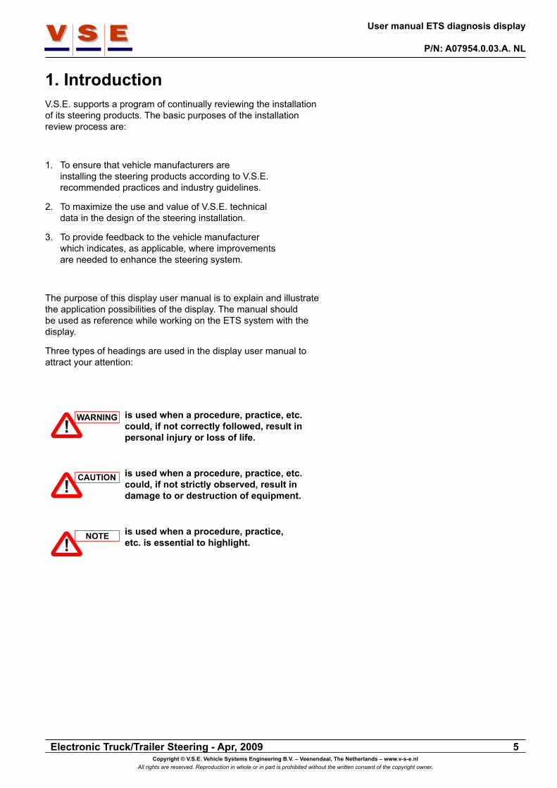
1. IntroductionV.S.E. supports a program of continually reviewing the installation of its steering products. The basic purposes of the installation review process are:
1. To ensure that vehicle manufacturers are installing the steering products according to V.S.E. recommended practices and industry guidelines.
2. To maximize the use and value of V.S.E. technical data in the design of the steering installation.
3. To provide feedback to the vehicle manufacturer which indicates, as applicable, where improvements are needed to enhance the steering system.
The purpose of this display user manual is to explain and illustrate the application possibilities of the display. The manual should be used as reference while working on the ETS system with the display.
Three types of headings are used in the display user manual to attract your attention:
is used when a procedure, practice, etc. could, if not correctly followed, result in personal injury or loss of life.
is used when a procedure, practice, etc. could, if not strictly observed, result in damage to or destruction of equipment.
is used when a procedure, practice, etc. is essential to highlight.
!WARNING
!CAUTION
!NOTE

Electronic Truck/Trailer Steering - Apr, 2009
User Manual ETS diagnosis display
P/N: A07954.0.03.A. EN
Copyright © V.S.E. Vehicle Systems Engineering B.V. – Veenendaal, The Netherlands – www.v-s-e.nlAll rights are reserved. Reproduction in whole or in part is prohibited without the written consent of the copyright owner.
6
2. GeneralThe purpose of this document is to get users become quickly familiar with the VSE/CANtrak display for the ETS system.
In the ETS control software, procedures are present to examine the statuses of all inputs and outputs and to calibrate the ETS system. This display will be easy controllable and the information given to the user shall be simple and clear so a diagnosis can be made easily.
The communication between ECU and display occurs by CAN.If no CAN communication is available, the display shows a big black sign with the text: “No CAN communication available”. In this case check the CAN-connection between ECU and display or the fuses of the ECU. The ECU decides whether a diagnosis routine can be carried out (dependent on speed and other data that is security critical).
The display is actual divided into two sections:
1. User section. This section is accessible for everybody and will show useful information about the system such as Vehicle Data and possible alarms.
2. Specialists section. This section is accessible with an entry code and gives access to the diagnose routines and calibration routines.
Every page has a unique number, it is placed in the right upper corner. (Figure 2). The display buttons in this manual are designated with [Btn x] where x is a number from 1 to 5. The numbering is from left to right, beginning with [Btn 1] till [Btn 5] (Figure 2).
When the [ESC] button is pushed and released the display will go back one page, when the button is pushed for about three seconds the display goes back to its main page (see chapter 3).The [ESC] button is always button 1.
Underneath every display picture is pinpointed in which autho-rization levels the screen is accessible (more details about the authorization levels, see chapter 5).
When the display is used for the first time, a choice must be made in what language the display must function. Select the language with the Up/Down buttons and press “OK”. The selected language is stored in the display memory so every time the display is started the same language is active. See also chapter 11 for display options.
!NOTE
Authorisation level: 0, 1, 2, 3
Dynamic System Control
General Info
ESCESC
1-1-1-1
Prod. Date: 06-10-2006
P/N: A07504.0.01S/N: 322
ECU SW: A07934V120Display SW: ETS CANtrak_V110
ETS2.22E9N-164
Btn 1 Btn 2 Btn 4 Btn 5Btn 3
Page no.
Figure 2
Authorisation level: 0
Dynamic System Control
ETS - System Check 1
ETS Status:Supply Voltages:
Snelheidssignaal:
On Off
Failure
OK
!
No CAN communicationavailable
Figure 1
Authorisation level: 0
Dynamic System Control
1
ESCESC OKOK
EnglishNederlands
Figure 3

Electronic Truck/Trailer Steering - Apr, 2009
User manual ETS diagnosis display
P/N: A07954.0.03.A. NL
Copyright © V.S.E. Vehicle Systems Engineering B.V. – Veenendaal, The Netherlands – www.v-s-e.nlAll rights are reserved. Reproduction in whole or in part is prohibited without the written consent of the copyright owner.
7
3. Main PageThis is the page that is showed when the display is started, the main page is also the default page and will be displayed when no button is pushed for about 30 minutes or when the “ESC” button is pushed for longer than 3 seconds.
There is a possibility to choose between two pages. To switch between the two pages, hold [Btn 5] pressed for about 5 seconds. The settings are stored so the next time the display starts up, the selected page will appear.
3.1 Main Page ETS - System Check (1)
This page simply shows the system status and if the vehicle signals are correct (figure 4). In the table below, the different items of the screen with there possible status are shown.
ETS - System Check (1)Item Possible
statusRemarks
ETS Status:(The mode of the ETS system)
Checking ... Each time when the ignition is switched on, the system is checked before it is operational.
Normal The system is in normal opera-tion mode.
Failure The system has an active alarm.Centring The system is centered.
(Centring Switch).Manual Manual steering mode is
activated.Diagnostic System is in diagnostic mode
(authorisation level 1, 2 of 3).
Supply Voltages:(The vehicle supply voltages)
Checking ... When the E-pump is running, the battery voltage will drop. At this moment “Checking...” is displayed because the system can not determine if the voltage is correct or incorrect.
OK Supply voltages are correct.Failure One of the voltages (KL15 of
KL30) or both voltages are incorrect.
Speed Signal:(Signal from the vehicle)
OK Speed signal is correct.Failure Signal is incorrect, check the
source of the signal
Authorisation level: 0, 1, 2, 3
Dynamic System Control
ETS - System Check 1
ETS Status:Supply Voltages:
Speed Signal:
On Off
NormalOKOK
!
Figure 4

Electronic Truck/Trailer Steering - Apr, 2009
User Manual ETS diagnosis display
P/N: A07954.0.03.A. EN
Copyright © V.S.E. Vehicle Systems Engineering B.V. – Veenendaal, The Netherlands – www.v-s-e.nlAll rights are reserved. Reproduction in whole or in part is prohibited without the written consent of the copyright owner.
8
3.2 Main page ETS (2)
On this page the most important status of the system is displayed (Figure 5). Depending of the configuration of the system, it is possible the page looks a bit different than shown.In the table below, the different items of the page are described.
ETS (2)Item DescriptionMode See next tableAF Angle Front (Kingpin or front axle angle)AE1 Angle of the first ETS axleAE2 Angle of the second ETS axleAT1 Target Angle of the first ETS axleAT2 Target Angle of the second ETS axleSpeed Speed of the vehicle (in Km/h or mph)Px Pressure in the X (steer) circuit of the ETS
system (in Bar or Psi)Py Pressure in the Y (centre) circuit of the ETS
system (in Bar or Psi)Tx Oil temperature in X circuit Ta Ambient temperatureIgnition Whether the ignition is on or off (motor runs)Battery The voltage of the (ETS) battery
ETS (2)Item Possible status RemarksMode:(Mode where the system is in)
Diagnostic Mode
System is in diagnostic mode (authorisation level 1, 2 or 3).
Alarm Mode The system has an active alarm.
Waiting for movement
The system waits for vehicle movement.
Centring The ETS axle(s) are centred (for example: due to a lift axle signal).
Normal Steering ETS system is functioning normal
Manual Centring When manual control is active and the centring switch on the remote is pushed
Manual Steering Manual control is active (remote control)
Authorisation level: 0, 1, 2, 3
Dynamic System Control
ETS 2
Mode:Normal Steering
On Off !
AF: -0.3°AE1: 0.2°AT1: 0.0°
Speed: 3 Km/hPx: 3 BarPy: 110 Bar
Ignition: On
AE2: -0.2°AT2: 0.0°
Tx: 15°CTa: 15°C
Battery: 24.4V
Figure 5
Electronic Truck/Trailer Steering - Apr, 2009
User manual ETS diagnosis display
P/N: A07954.0.03.A. NL
Copyright © V.S.E. Vehicle Systems Engineering B.V. – Veenendaal, The Netherlands – www.v-s-e.nlAll rights are reserved. Reproduction in whole or in part is prohibited without the written consent of the copyright owner.
9
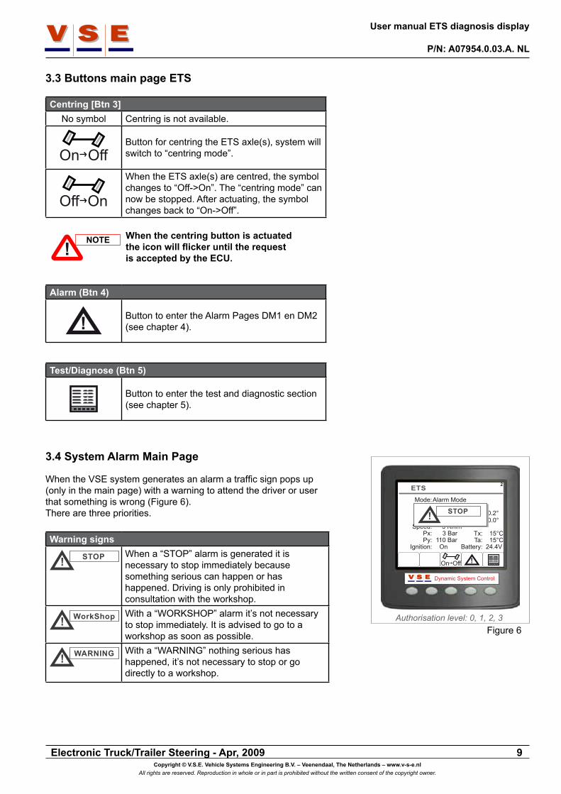
3.3 Buttons main page ETS
Centring [Btn 3]No symbol Centring is not available.
On OffButton for centring the ETS axle(s), system will switch to “centring mode”.
Off On
When the ETS axle(s) are centred, the symbol changes to “Off->On”. The “centring mode” can now be stopped. After actuating, the symbol changes back to “On->Off”.
When the centring button is actuated the icon will flicker until the request is accepted by the ECU.
Alarm (Btn 4)
! Button to enter the Alarm Pages DM1 en DM2 (see chapter 4).
Test/Diagnose (Btn 5)
Button to enter the test and diagnostic section (see chapter 5).
3.4 System Alarm Main Page
When the VSE system generates an alarm a traffic sign pops up (only in the main page) with a warning to attend the driver or user that something is wrong (Figure 6). There are three priorities.
Warning signs
! STOP When a “STOP” alarm is generated it is necessary to stop immediately because something serious can happen or has happened. Driving is only prohibited in consultation with the workshop.
! WorkShop With a “WORKSHOP” alarm it’s not necessary to stop immediately. It is advised to go to a workshop as soon as possible.
! WARNING With a “WARNING” nothing serious has happened, it’s not necessary to stop or go directly to a workshop.
Authorisation level: 0, 1, 2, 3
Dynamic System Control
ETS 2
Mode:Alarm Mode
On Off !
AF: -0.3°AE1: 0.2°AT1: 0.0°
Speed: 3 Km/hPx: 3 BarPy: 110 Bar
Ignition: On
AE2: -0.2°AT2: 0.0°
Tx: 15°CTa: 15°C
Battery: 24.4V
! STOP
Figure 6
!NOTE

Electronic Truck/Trailer Steering - Apr, 2009
User Manual ETS diagnosis display
P/N: A07954.0.03.A. EN
Copyright © V.S.E. Vehicle Systems Engineering B.V. – Veenendaal, The Netherlands – www.v-s-e.nlAll rights are reserved. Reproduction in whole or in part is prohibited without the written consent of the copyright owner.
10
SRC SPN
FMI OC
Figure 7
Authorisation level: 0, 1, 2, 3
Dynamic System Control
3-1
ESCESC DM2i
1234567
0x380x380x380x380x380x380x38
0x7F4230x7F4710x7F4410x56B0x56B0xA2A0x7F402
0x1F0x20xA0xF0x100x10x2
1111111
SRC SPN FMI OCDM1 Total Alarms = 16
Figure 8
Authorisation level: 0, 1, 2, 3
Dynamic System Control
3-1
ESCESC DM2i
1234567
0x380x380x380x380x380x380x38
0x7F4230x7F4710x7F4410x56B0x56B0xA2A0x7F402
0x1F0x20xA0xF0x100x10x2
1111111
SRC SPN FMI OCDM1 Total Alarms = 16
Alarm InformationNo: 3 0x7F441 0xASpeed increases too fast
Figure 9
Who sends the message?
e.g. ETS ECU
What causes the failure?
e.g. sensor PSX
How many times has this failure happened
How did the signal/component fail? e.g. open circuit
4. Alarm pages (DMx)The alarm structure of the ETS system is based on the SAE J1939 diagnostic trouble code handling (DMx).The used DMx messages are:
■ DM1: Active trouble codes
■ DM2: Stored trouble codes
■ DM3: Clear all stored trouble codes
Figure 7 shows the set up of a DMx message.
4.1 DM1, active trouble codes
This page (Figure 8) displays the active trouble codes of the ETS system. On top of the page, the total number of alarms is displayed that are currently active. The trouble codes are displayed in order of occurrence with the last occurred alarm at the top. To scroll through the trouble codes, use the up/down arrow buttons (Btn 2 and Btn 3). With the information button [( i )] extra information about the selected trouble code is displayed (Figure 9). It is also possible to scroll through the trouble codes with the alarm information on.
With the [DM2] button the DM2 (stored trouble codes) page is opened.
For a complete overview of all possible trouble codes, refer to Spec 138.!
NOTE

Electronic Truck/Trailer Steering - Apr, 2009
User manual ETS diagnosis display
P/N: A07954.0.03.A. NL
Copyright © V.S.E. Vehicle Systems Engineering B.V. – Veenendaal, The Netherlands – www.v-s-e.nlAll rights are reserved. Reproduction in whole or in part is prohibited without the written consent of the copyright owner.
11
4.2 DM2, stored trouble codes
When the VSE system generates an alarm, the trouble code is stored in the system memory at the moment that the vehicle ignition is switched off. Just like the DM1 page, the stored trouble codes on the DM2 page are displayed in order of occurrence with the last occurred alarm at the top (Figure 10). To scroll through the trouble codes, use the up and down arrow keys (Btn 2 and Btn 3). With the information button [( i )] extra information about the selected trouble code is displayed (This is the same as the DM1 page, see Figure 9). It is also possible to scroll through the trouble codes with the alarm information on.
With the [DM1] button the DM1 (active trouble codes) page is opened again.
For a complete overview of all possible trouble codes, refer to Spec 138.
4.3 DM3, clear stored trouble codes
When the user is logged on in authorisation level 1, 2 or 3, it is possible to clear all the stored trouble codes from the system memory . In authorisation level 1, 2 and 3, button 5 has an extra function in the DM2 page. To clear messages: push and hold button [DM1/3] (Btn 5) for about three seconds. A pop-up will appear with the question: “Are you sure to clear all the DM2 messages (Yes/No)” (Figure 11). When the question is answered with [No] the display returns to the DM2 page (Figure 10). If the question for clearing is confirmed with [Yes] all codes will be cleared from the memory and a pop-up appears with the message that the display and ECU must be reset by switching the ignition off and on (Figure 12).
Wait at least 5 seconds between switching the ignition off and on. After reset, the authorisation level is set to level 0.
!NOTE
Authorisation level: 0, 1, 2, 3
Dynamic System Control
3-2
ESCESC DM1i
1234567
0x380x380x380x380x380x380x38
0x7F4040x7F4040x7F4040x7F4020x7F4000x56B0x7F402
0x110xD0x40xD0xD0xD0x11
1111111
SRC SPN FMI OCDM2 Total Alarms = 7
Figure 10
Authorisation level: 1, 2, 3
Dynamic System Control
3-2
ESCESC
1234567
0x380x380x380x380x380x380x38
0x7F4040x7F4040x7F4040x7F4020x7F4000x56B0x7F402
0x110xD0x40xD0xD0xD0x11
1111111
SRC SPN FMI OCDM2 Total Alarms = 7
Are you sure to clearall DM2 messages(Yes/No).
YesYes NoNo
Figure 11
Authorisation level: 1, 2, 3
Dynamic System Control
3-2
ESCESC
SRC SPN FMI OCDM2 Total Alarms = 0
Reset Display and ECU by switching contactoff and on.
Figure 12
!NOTE

Electronic Truck/Trailer Steering - Apr, 2009
User Manual ETS diagnosis display
P/N: A07954.0.03.A. EN
Copyright © V.S.E. Vehicle Systems Engineering B.V. – Veenendaal, The Netherlands – www.v-s-e.nlAll rights are reserved. Reproduction in whole or in part is prohibited without the written consent of the copyright owner.
12
5. Main MenuWhen in the main page the “Test\Diagnose” button (Btn 5) is pushed, the main menu page appears (Figure 13). A menu item can be selected with the up/down arrow buttons and confirmed with the [OK] button. Depending of the authorisation level, the menu will be enlarged with more menu items (see Figure 14)
The next table shows which menu item is displayed in which authorisation level:
Main MenuMenu item Authorisation levelLogin (Log on) 0, 1, 2, 3ECU Info 0, 1, 2, 3System Data 0, 1, 2, 3
(in level 0 and 1 read only)Diagnostic Routines 1, 2, 3
(in level 1 only Manual Steering)System Calibration 1, 2, 3
(in level 1 only Calibration Data)Display Options 0, 1, 2, 3
Authorisation level: 0
Dynamic System Control
1-1
ESCESC
Main Menu
LoginECU InfoSystem DataDisplay Options
OKOK
Figure 13
Authorisation level: 1, 2, 3
Dynamic System Control
1-1
ESCESC
Main Menu
LoginECU InfoSystem DataDiagnostic RoutinesSystem CalibrationDisplay Options
OKOK
Figure 14

Electronic Truck/Trailer Steering - Apr, 2009
User manual ETS diagnosis display
P/N: A07954.0.03.A. NL
Copyright © V.S.E. Vehicle Systems Engineering B.V. – Veenendaal, The Netherlands – www.v-s-e.nlAll rights are reserved. Reproduction in whole or in part is prohibited without the written consent of the copyright owner.
13
6. LoginThe display is divided in four authorization levels. Three user levels and one ‘VSE’ level.
Authorisation levelLevel Description
0 For everybody. When the display starts up, it’s in level 0.
1 User level 1 (Driver).2 User level 2 (Workshop).3 Only for experts / developers.
6.1 Select authorisation level
When from the main menu “Login” is chosen, the “Authorization Lvl (x)” screen appears (see Figure 15). The number between the brackets indicates the actual level. Select the authorization level with the [+] button and confirm with the [OK] button.
6.2 Fill in code
When the level is chosen and confirmed, the screen will be enlarged with a fill in field for the “Login Code” (Figuur 16).
The code consists of 5 numbers between 0 and 9. With the [+] and [-] button the numbers can be seperately increased or decreased. With the arrow button (Btn 5) the cursor jumps one position to the right. Use button 2 to erase the complete field when a wrong code is filled in.
After finishing the fifth number of the code, the arrow button (Btn 5) must be pressed one more time. The screen of the display changes and the chosen level must be confirmed (see figure 17). Press the [OK] button and when the code is accepted, the display will confirm that. Press one more time the [OK] button and the display returns to the main menu (figure 14).
Authorisation level: 0, 1, 2, 3
Dynamic System Control
ESCESC
Authorization Lvl (0) 1-1-6
Authorization level 0
OKOK
Figure 15
Authorisation level: 1, 2, 3
Dynamic System Control
ESCESC
Authorization Lvl (0) 1-1-6
Authorization levelLogin Code
28
Figure 16
Authorisation level: 1, 2, 3
Dynamic System Control
ESCESC
Authorization Lvl (0) 1-1-6
Authorization levelLogin Code
2
OKOK
Figure 17

Electronic Truck/Trailer Steering - Apr, 2009
User Manual ETS diagnosis display
P/N: A07954.0.03.A. EN
Copyright © V.S.E. Vehicle Systems Engineering B.V. – Veenendaal, The Netherlands – www.v-s-e.nlAll rights are reserved. Reproduction in whole or in part is prohibited without the written consent of the copyright owner.
14
6.3 Change Code
The login codes for authorization level 1 and 2 can be changed. First select a level (see par 6.1) and press [Btn 2]. The “Change Login Code” screen appears (Figure 18).
Filling in the codes works the same way as described in paragraph 6.2. First fill in the old code and after that the new code. To verify the new code, re-enter it again.
When the codes are entered, “Code changed. Level x” pops up. If a wrong old code is entered then a pop-up will appear with the message: “Wrong code. attempt x/3”. After three wrong attempts the display is reset to the main page.When the first and second new codes are not corresponding, a pop-up appears with the message: “New codes not corresponding”. Authorisation level: 1, 2
Dynamic System Control
0
ESCESC
Change Login Code 1-1-6-1
Authorization level 2Enter Old
Enter NewRe-enter New
Figure 18

Electronic Truck/Trailer Steering - Apr, 2009
User manual ETS diagnosis display
P/N: A07954.0.03.A. NL
Copyright © V.S.E. Vehicle Systems Engineering B.V. – Veenendaal, The Netherlands – www.v-s-e.nlAll rights are reserved. Reproduction in whole or in part is prohibited without the written consent of the copyright owner.
15
7. ECU Info
7.1 General Info
When from the main menu “ECU Info” is chosen, a new menu appears (Figuur 19).
In the “General Info” page, information is available to identify the connected ECU and the version of the software in the ECU and display (Figure 20).In the table below, the different items of the screen are described.
General InfoItem DescriptionProd. Date Production date of the ECU. When the ECU is
tested and the software is downloaded.S/N Serial number, unique number of the ECU.P/N Part number. VSE Article number of the ECU
without software.ECU SW Part number of the software in the ECU.Display SW Part number of the software in the Display.(Bottom line) ETS application code.
7.2 Application Sheet
In the application sheets the configuration of the connected vehicle can be read out (Figure 21).The items on these two pages correspond to the Customer/VSE application sheets on which the ETS software is build. With the up/down arrow buttons it’s possible to scroll through the items. Use [Btn 4] to switch between the customer and VSE sections.
Authorisation level: 0, 1, 2, 3
Dynamic System Control
1-1-1
ESCESC
ECU Info
General InfoApplication Sheet
OKOK
Figure 19
Authorisation level: 0, 1, 2, 3
Dynamic System Control
General Info
ESCESC
1-1-1-1
Prod. date: 22-09-2008
P/N: A07504.0.01S/N: 168
ECU SW: A06836V120Display SW: A07696_V110
ETS1.12E4D-173
Figure 20
Authorisation level: 2, 3
Dynamic System Control
1-1-1-2-1
ESCESC
Application SheetCustomer:
SteeringType Vehicle TrailerType Axle FuseeNmbr steered axle 2Max desired steerangle -95°Ackermann NoDirect Startup NoAxle configurationAxle configuration 3
Figure 21

Electronic Truck/Trailer Steering - Apr, 2009
User Manual ETS diagnosis display
P/N: A07954.0.03.A. EN
Copyright © V.S.E. Vehicle Systems Engineering B.V. – Veenendaal, The Netherlands – www.v-s-e.nlAll rights are reserved. Reproduction in whole or in part is prohibited without the written consent of the copyright owner.
16
8. System data
8.1 General
These pages are only accessible in authorisation level 0, 1, 2 and 3, with exception of the “Read/Write Memory` screen. This screen is not accessible in level 0 and 1. In the “System Data” screen, several data can be watched. For example: inputs , outputs and supply voltages of the ECU. Select with the up/down arrow buttons an item in the list and press the “OK” button to confirm.
8.2 Supply Voltage
The “Supply Voltage” page contains all power supply voltages and sensor power supply voltages, used in the ECU (Figure 23). The next table describes the different items of this page.
Supply VoltageItem DescriptionKL15 Switched power supply voltage (ignition).KL30 Constant power supply voltage.KL15/30 Combined power supply, used as power
supply for the outputs.VCC Internal (PCB board) power supply.U6 Pre-voltage for internal power supply.ASR Angle Sensor signal adoption reference
supply voltage.VPS Pressure sensors power supply.VAS Angle sensors power supply.
In this example, behind KL30 the value is NA V. This doesn’t mean that the KL30 is not connected. It means that the value is Not Available for displaying.
8.3 Outputs
When “Outputs” is chosen from the “System Data” menu, a new menu appears with two items (Figure 24).
■ High Outputs: These outputs can be switched to power supply by the ECU.
■ Low Outputs: These outputs can be connected to ground by the ECU.
On these pages all outputs are displayed and can be switched on or off (switching outputs on and off is only possible in authorisation level 2 and 3).
!NOTE
Authorisation level: 0, 1, 2, 3
Dynamic System Control
1-1-2
ESCESC
System Data
Supply VoltageOutputsInputsRead/Write Memory
OKOK
Figure 22
Authorisation level: 0, 1, 2, 3
Dynamic System Control
1-1-2-1
ESCESC
Supply Voltage
KL15 :KL30 :
KL1530 :Vcc :U6 :
ASR :VPS :VAS :
25.0 VNA V
25.1 V5.0 V6.3 V2.5 V5.0 V5.0 V
Figure 23
Authorisation level: 0, 1, 2, 3
Dynamic System Control
1-1-2-2
ESCESC
Outputs
High OutputsLow Outputs
OKOK
Figure 24

Electronic Truck/Trailer Steering - Apr, 2009
User manual ETS diagnosis display
P/N: A07954.0.03.A. NL
Copyright © V.S.E. Vehicle Systems Engineering B.V. – Veenendaal, The Netherlands – www.v-s-e.nlAll rights are reserved. Reproduction in whole or in part is prohibited without the written consent of the copyright owner.
17
8.3.1 High Outputs
In the “High Output” page the different values and statuses of the used outputs are represented (Figure 25). In the first column, the names of the outputs are displayed. The second column displays the current through the coil and third column the ohmic value of the coil. The pin connection on the ECU is displayed in the last column.
With the down arrow button the desired output can be selected. The outputs can be switched in two different ways. With the [Cont.] button the selected output will constant turned ‘ON’. Is the button pushed again the output is turned “OFF”.When the [1/0] button is pushed the output is turned ‘ON’, when the button is released the output will turn ‘OFF’.
It’s possible the number of outputs and the names are different from Figure 25, these are application dependent.
8.3.2 Low Outputs
In the “Low Outputs” page the statuses of the low outputs are represented (Figure 26). In the first column, the names of the outputs are displayed The pin connection on the ECU is displayed in the last column
With the down arrow button the desired output can be selected. The outputs can be switched in two different ways. With the [Cont.] button the selected output will constant turned ‘ON’. Is the button pushed again the output is turned “OFF”.
When testing the pump, Don’t leave it on too long (max. 30 seconds).
When the [1/0] button is pushed the output is tuned “ON”. When the button is released the output will turn “OFF”.
It’s possible the number of outputs and the names are different from Figure 26, these are application dependent.
Authorisation level: 2, 3
Dynamic System Control
1-1-2-2-1
ESCESC 1/01/0
SP011SP201SP051SP071SP041SP012SP052
16581523
01101
1415- -- -- -- -- -
A-OnA-OnA-OffA-OffA-OffA-OffA-Off
B16/17B13/14B10/11B07/08B04/05A16/17A10/11
Output (mA) (Ohm) Sts Pin
KL30: 24.8V KL1530: 24.4VCont.Cont.
Figure 25
!NOTE
Authorisation level: 2, 3
Dynamic System Control
1-1-2-2-2
ESCESC 1/01/0
FunctionLampPump
A-OnA-Off
C01 C02
Output Str Pin
KL15: 25.1V KL30: 25.0VCont.Cont.
Figure 26
!NOTE
!CAUTION

Electronic Truck/Trailer Steering - Apr, 2009
User Manual ETS diagnosis display
P/N: A07954.0.03.A. EN
Copyright © V.S.E. Vehicle Systems Engineering B.V. – Veenendaal, The Netherlands – www.v-s-e.nlAll rights are reserved. Reproduction in whole or in part is prohibited without the written consent of the copyright owner.
18
8.4 Inputs
When “Inputs” is chosen from the “System Data” menu, a new menu appears with three items (Figure 27).
■ Analog Inputs: These are the inputs from the angle sensors and pressure sensors.
■ Digital Inputs: These are inputs from (on/off) switches.
■ CAN Communication: On this page, the CAN data of the CAN-bus is displayed.
8.4.1 Analog Inputs
On the “Analog Inputs” page (Figure 28), the values of the analog inputs are showed.The Analog Input values are given in volts. The pin connection on the ECU is displayed in the last column. The table below describes all existing analog inputs.
Analoge InputsItem DescriptionASFm Main Front angle signal or king pin sensor
signal.ASFr Redundant Front angle signal or king pin
sensor signal.ASE1m Main Rear angle signal on the first ETS axle.ASE1r Redundant Rear angle signal on the first
ETS axle.PSX Steering pressure sensor signal.PSY Centring pressure sensor signal.ASE2m Main Rear angle signal on the second ETS
axle. ASE2r Redundant Rear angle signal on the second
ETS axle.VAS Angle sensors power supplyVPS Pressure sensors power supply
The page with analog inputs is application dependent, therefore it is possible that the number of inputs and there names can differ from the example of Figure 28.
Authorisation level: 0, 1, 2, 3
Dynamic System Control
1-1-2-3
ESCESC
Inputs
Analog InputsDigital InputsCAN Communication
OKOK
Figure 27
Authorisation level: 0, 1, 2, 3
Dynamic System Control
1-1-2-3-1
ESCESC
ASFmASFrASE1mASE1rPSXPSYASE2mASE2r
4.43V4.55V0.90V1.03V2.26V1.04V0.00V4.21V
C14C13C12C11C10C09C08C07
Input V Pin
VAS: 5.0V VPS: 5.0V
Figure 28
!NOTE

Electronic Truck/Trailer Steering - Apr, 2009
User manual ETS diagnosis display
P/N: A07954.0.03.A. NL
Copyright © V.S.E. Vehicle Systems Engineering B.V. – Veenendaal, The Netherlands – www.v-s-e.nlAll rights are reserved. Reproduction in whole or in part is prohibited without the written consent of the copyright owner.
19
8.4.2 Digital Inputs
On this page (Figure 29) the status of the digital inputs are showed, whether they are “On” or “Off”. For the oil level switch the status will be displayed with “Low” or “Ok”.The type of input is displayed with “L” or “H”, this are Low inputs (switched to ground) or high inputs (switched to power supply)The pin connection on the ECU is displayed in the last column.
The page with digital inputs is application dependent, therefore it is possible that the number of inputs and there names can differ from the example of Figure 29.
8.4.3 CAN Communication
On the CAN communication page the status of the CAN bus is displayed and it shows all the received CAN messages on the CAN-bus (Figure 30).
Column 1 displays the PGN: Parameter Group Number.
Column 2 displays the SA : Source Address.
Column 0-7 displays the CAN data.
With the up/down arrow buttons it is possible to scroll trough the messages.The [SA] button (Btn 4) will sort the data by Source Adres. The symbol of this button will change to [PGN] when the data is sorted by “SA”, Pushing the button again the data will sort by Parameter Group Number.By pushing [Btn 5] for 5 seconds, only the CAN messages send by the ETS system are shown. Pushing [Btn 5] for 5 seconds again, all messages will be displayed. With a short push on [Btn 5], the page will refresh.
8.5 Read/Write Memory
The “Read/Write Memory” page is specially made for advanced servicing purposes and is only needed to access when VSE personnel asks for it. On this page certain data can be read from the “Flash” memory or read from the Eeprom.
To write data, authorisation level 3 is required.
Authorisation level: 0, 1, 2, 3
Dynamic System Control
1-1-2-3-2
ESCESC
Centring switch (RC)Steer right (RC)Steer left (RC)Manual control (RC)Centring switchOil Level switch
OffOnOffOffOffOK
H B09L A12L A09L A03L B15L B12
Input Sts Type Pin
Figure 29
!NOTE
Authorisation level: 0, 1, 2, 3
Dynamic System Control
1-1-2-3-4
ESCESC
EBA4ECA4FF10FF11FF18FF20FF28FF30FF31FF38
SA38383838383838383838
008100101FFF0F1CA79BB
101360000FFF0F0090201
202000400FFF0FFC7FAC7
3F4080000FFF0FF090000
4F1FF0003FFF0FFCAF65A
501380000FFF0FF090100
600CA0707FFF0FFF7F567
7DEFE0000FFF0FF010100
ETSSA
Figure 30
Authorisation level: 2, 3
Dynamic System Control
1-1-2-4
ESCESC
R/W Memory
Flash/EepromRead/WriteStart AddressNmbr of bytes
EepromRead0x000032
Figure 31

Electronic Truck/Trailer Steering - Apr, 2009
User Manual ETS diagnosis display
P/N: A07954.0.03.A. EN
Copyright © V.S.E. Vehicle Systems Engineering B.V. – Veenendaal, The Netherlands – www.v-s-e.nlAll rights are reserved. Reproduction in whole or in part is prohibited without the written consent of the copyright owner.
20
9. Diagnostic Routines
9.1 General
These pages are only accessible in authorisation level 2 and 3. With the diagnostic routines it’s possible to test the basic functions of the ETS system (Figure 32). Select with the up/down arrow buttons an item in the list. With the “OK” button the choice is confirmed and the respective test screen will open.When a test can not be executed, because one of the conditions does not comply with the conditions to execute that test, a pop-up appears after opening the test page: (e.g. ERROR: D2; Speed signal too high).
The test routines must only be executed by persons with knowledge of the ETS system.
During some test routines, it is possible that the rear axle moves. Make sure that the surrounding of ETS axles are clear from any persons and obstacles so the axles can move freely.
The layout of each test page looks more or less similar. In the upper part the values of the angle sensors and pressure sensors are displayed. The part in the middle of the page displays the current supply through the coils of every on-hand valve. Also the vehicle speed and the supply voltage KL15 and KL30 are displayed. The buttons in each test can differ, depending of the functionality required in the test.
9.2 Pump Test
With this test it is possible to check the pump pressure and the functionality of the release valves SP051 and SP052 (Figure 33). The [Start] button activates the E-pump and the maximum pressure is set. For applications with a engine driven pump, only the maximum pressure is set (the maximum pressure is set by the pressure relieve valve SP201, this setting is application dependent). With the [SP051] and [SP052] buttons, the release valves can be switched on or off.
9.3 Px Py Fill/Release
On this page (Figure 34) the following tests can be done:
1. Check and verify the pressure sensors (Px and Py).
2. Fill and release the oil pressure in the centring circuit.
Button [SP041] activates the accumulator fill/release valve. The [Pump] button activates the E-pump (for applications with a engine driven pump, this button is not present). Button [SP201] sets the
!WARNING
!CAUTION
Authorisation level: 2, 3
Dynamic System Control
1-1-3
ESCESC
Diagnostic Routines
Pump TestPx Py Fill/ReleaseCentre on PYGas PrepressureSP011 SP012 MidposSP071 Test/AirtestManual steeringSet PRV-xFlow TestAlign ETS Axle
OKOK
Figure 32
Authorisation level: 2, 3
Dynamic System Control
1-1-3-1
ESCESC
AF:AE1:AE2:
Start
Pump Test0.0°
-0.1°-0.2°
SP011:SP201:SP051:SP071:
Px: 0 barPy: 101 bar
SP041:SP012:
SP052:
1 mA849 mA
1 mA
854 mA3 mA1 mA
625 mA1 Km/h
KL15: 25.1 VSpeed:
KL30: 25.0 V
SP051SP052Off->On Off->On Hold
Figure 33
Authorisation level: 2, 3
Dynamic System Control
1-1-3-2-B
ESCESC
AF:AE1:AE2:
Px Py Fill/Release0.0°
-0.1°-0.2°
Sp011:Sp201:Sp051:Sp071:
Px: 0 barPy: 101 bar
Sp041:Sp012:
Sp052:
1 mA849 mA
1 mA
854 mA3 mA1 mA
625 mA1 Km/h
KL15: 25.1 VSnelh:KL30: 25.0 V
Release
Centreerdruk: 100
StartHold
Figure 34

Electronic Truck/Trailer Steering - Apr, 2009
User manual ETS diagnosis display
P/N: A07954.0.03.A. NL
Copyright © V.S.E. Vehicle Systems Engineering B.V. – Veenendaal, The Netherlands – www.v-s-e.nlAll rights are reserved. Reproduction in whole or in part is prohibited without the written consent of the copyright owner.
21
Authorisation level: 2, 3
Dynamic System Control
1-1-3-3
ESCESC
AF:AE1:AE2:
Start
Centre on Py0.0°
-0.1°-0.2°
Sp011:Sp201:Sp051:Sp071:
Px: 0 barPy: 101 bar
Sp041:Sp012:
Sp052:
1 mA849 mA
1 mA
854 mA3 mA1 mA
625 mA1 Km/h
KL15: 25.1 VSpeed:
KL30: 25.0 V
L 1 R 1Hold
CentrePressure: 100
Figure 35
maximum pump pressure. This pressure is application dependent.
9.4 Centre on PY
With this test (Figure 35) the ETS axle(s) can be centred with the centring pressure Py. With a ETS2 system there can also be checked if both release valves SP051 and SP052 are connected correctly. With the [L1] and [R1] buttons the ETS axle(s) can be steered to the left or right. For an ETS2 system, button 5 can be used to make different settings like which axle must steer and the status of the release valves SP051 and SP052. The symbols of the buttons [L1] and [R1] will change due to the different settings made by button 5. By pushing the [Start] button, the axle(s) will be pushed in there mid-position by the centring pressure.
When a vehicle with a heavy load is stationary, the axles may not be able to steer to the desired position. In this case, allow the vehicle to roll slowly or jack-up the axles.
9.5 Gas Prepressure
By means of this test can be determined how high the initial pressure of the nitrogen is in the accumulator of the centring circuit. (Figure 36). With the [Fill] button, the accumulator is filled with oil. When the accumulator is filled with oil and the [Start] button is pressed, the oil will be released slowly from the accumulator (Py value will decrease). The moment that the oil pressure is equal to the initial pressure of the nitrogen, the value behind Py wil stop decreasing for a second, before it drops to zero.
9.6 SP071 Test/Airtest
This test gives the possibility to check if there’s air in the centring circuit and to check the functionality of SP071. With the arrow button (Btn 2) a choice can be made between steer-ing left, steering right or no steering. With button 3 a choice can be made which cylinder of which axle must be tested. The test starts by pushing the [Start] button. The last line of the page displays the boundary values of the angles of the axles. These values are application dependent. By releasing the [Start] button, the test stops.
!NOTE
Authorisation level: 2, 3
Dynamic System Control
1-1-3-4
ESCESC
AF:AE1:AE2:
Start
Gas Prepressure0.0°
-0.1°-0.2°
Sp011:Sp201:Sp051:Sp071:
Px: 3 barPy: 101 bar
Sp041:Sp012:
Sp052:
1 mA849 mA
1 mA
854 mA3 mA1 mA
625 mA1 Km/h
KL15: 25.1 VSpeed:
KL30: 25.0 VGasPrepressure: 80 EL.Pump
Fill
Figure 36
Authorisation level: 2, 3
Dynamic System Control
1-1-3-6
ESCESC
AF:AE1:AE2:
SP071 Test/Airtest0.0°
-0.1°-0.2°
Sp011:Sp201:Sp051:Sp071:
Px: 0 barPy: 101 bar
Sp041:Sp012:
Sp052:
1 mA1 mA
1 mA
1 mA3 mA1 mA4 mA
1 Km/hKL15: 25.1 V
Speed:KL30: 25.0 V
1None HoldStart
Axle1: 00 0° Axle2: 00 0°
Figure 37

Electronic Truck/Trailer Steering - Apr, 2009
User Manual ETS diagnosis display
P/N: A07954.0.03.A. EN
Copyright © V.S.E. Vehicle Systems Engineering B.V. – Veenendaal, The Netherlands – www.v-s-e.nlAll rights are reserved. Reproduction in whole or in part is prohibited without the written consent of the copyright owner.
22
9.7 Manual Steering
This test makes it possible to steer one or both axles manually (Figure 38). With button 4 a choice can be made to steer the first, the second or both ETS axles. The number above the button indicates the choice. With the buttons [L] and [R] the axle(s) can be steered to the left or to the right.
9.8 Set PRV-x
In some applications pressure relief valves are placed in the steering pipes to the ETS cylinder. These valves should prevent that external steering forces produce high pressure in the ETS cylinder and induce damage ( e.g. collide with a turntable axle against a kerb). On the last line of the “Set PRV-x” page, the set pressure for the pressure relief valves are displayed (Figure 39). These values are application dependent. With the [PRV-x] button a pressure relief valve can be selected. The [Start] button starts the test. The cylinder of which pressure relief valve is selected, will be steered to its maximum. For more information: see the adjustment procedure for PRV-x.
9.9 Flow Test
This test checks if the oil flow of the pump is sufficient to steer the ETS axle(s) fast enough.
For this test it is necessary that the wheels of the ETS axles are lifted from the ground.
The last line on the “Flow Test” page (Figure 40) displays the maximum time to steer the ETS axles completely from left to right or vice-versa. This time is application dependent and is displayed in seconds. With the arrow buttons (Btn 2 and 3), the ETS axles can be steered to the left and to the right. The moment that one of the buttons is pushed, a time counter above the respective button will start to run. When the button is released, the time counter will stop. To execute the test properly, first steer the axles completely to one side. Subsequently steer to the other side and release the button the moment that there is no movement in the ETS axles any more. When the pump delivers enough oil flow, the time above the button is less than the “Max. time” displayed on the last line of the page.
Authorisation level: 2, 3
Dynamic System Control
1-1-3-8
ESCESC
AF:AE1:AE2:
Set RRV-x0.0°
-0.1°-0.2°
Sp011:Sp201:Sp051:Sp071:
Px: 0 barPy: 101 bar
Sp041:Sp012:
Sp052:
1 mA1 mA
1 mA
1 mA3 mA1 mA4 mA
1 Km/hKL15: 25.1 V
Speed:KL30: 25.0 V
PRV1
Start
PRV-x. 1: 0 2: 0 3: 0 4: 0
PRV-x
Figure 39!NOTE
Authorisation level: 2, 3
Dynamic System Control
1-1-3-9
ESCESC
AF:AE1:AE2:
Flow Test0.0°
-0.1°-0.2°
Sp011:Sp201:Sp051:Sp071:
Px: 0 barPy: 101 bar
Sp041:Sp012:
Sp052:
1 mA1 mA
628 mA
1 mA944 mA630 mA626 mA
1 Km/hKL15: 25.1 V
Speed:KL30: 25.0 V
0000.0
Max. time: 25.00000.0
Figure 40
Authorisation level: 2, 3
Dynamic System Control
1-1-3-7
ESCESC
AF:AE1:AE2:
Manual steering0.0°
-0.1°-0.2°
Sp011:Sp201:Sp051:Sp071:
Px: 0 barPy: 101 bar
Sp041:Sp012:
Sp052:
1 mA849 mA
1 mA
854 mA3 mA1 mA
625 mA1 Km/h
KL15: 25.1 VSpeed:
KL30: 25.0 V
L R1
Figure 38
Electronic Truck/Trailer Steering - Apr, 2009
User manual ETS diagnosis display
P/N: A07954.0.03.A. NL
Copyright © V.S.E. Vehicle Systems Engineering B.V. – Veenendaal, The Netherlands – www.v-s-e.nlAll rights are reserved. Reproduction in whole or in part is prohibited without the written consent of the copyright owner.
23
Authorisation level: 2, 3
Dynamic System Control
1-1-3-A
ESCESC
AF:AE1:AE2:
Align ETS Axle0.0°
-0.1°-0.2°
Sp011:Sp201:Sp051:Sp071:
Px: 0 barPy: 101 bar
Sp041:Sp012:
Sp052:
1 mA1 mA
1 mA
1 mA3 mA1 mA4 mA
1 Km/hKL15: 25.1 V
Speed:KL30: 25.0 V
Start
Figure 41
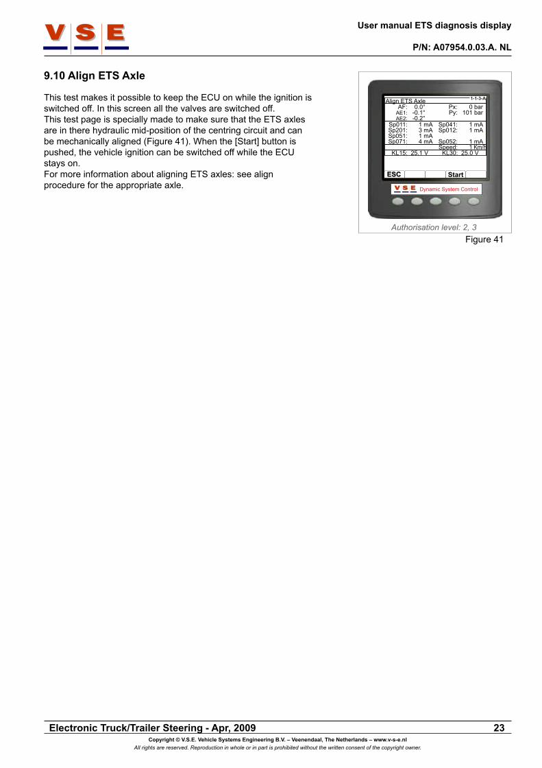
9.10 Align ETS Axle
This test makes it possible to keep the ECU on while the ignition is switched off. In this screen all the valves are switched off. This test page is specially made to make sure that the ETS axles are in there hydraulic mid-position of the centring circuit and can be mechanically aligned (Figure 41). When the [Start] button is pushed, the vehicle ignition can be switched off while the ECU stays on. For more information about aligning ETS axles: see align procedure for the appropriate axle.

Electronic Truck/Trailer Steering - Apr, 2009
User Manual ETS diagnosis display
P/N: A07954.0.03.A. EN
Copyright © V.S.E. Vehicle Systems Engineering B.V. – Veenendaal, The Netherlands – www.v-s-e.nlAll rights are reserved. Reproduction in whole or in part is prohibited without the written consent of the copyright owner.
24
10. System Calibration
10.1 General
The calibration data can be viewed in authorisation level 1, 2 and 3. The calibration routines can only be executed in authorisation level 2 and 3.From this section all system tests and calibration routines can be called and the calibration data can be viewed (Figure 42).For detailed information about the calibration of a vehicle, refer to the calibration instructions for the specific vehicle.
The test routines must only be executed by persons with knowledge of the ETS system.
10.2 Calibration Data
The configuration parameters are parameters that are provided by the ECU after a vehicle is calibrated.The configuration parameters are divided into three (1 ETS axle) or four (2 ETS Axles) pages, to switch between the pages use the buttons [1/4], [2/4], [3/4] and [4/4] (Figure 43).
When in one of the pages a value is shown as ”-- --”, it means: no value available or defined.
10.2.1 Sensor parameters (1/4), (2/4), (3/4)
The data in the pages 1/4, 2/4 and 3/4 look all the same (Figure 43). Page 1 displays the data from the front angle sensor, page 2 the data from the sensor of the first ETS axle and page 3 (if present) the data from the sensor of the second ETS axle.
The “Angle Sensor Parameters” exist of the sensor parameters (Middle, Left and Right) and the correction parameters.The sensor parameters are values (hexadecimal) obtained during maximal left, maximal right steering in the calibration routines and the calculated middle point of the sensor.The correction parameters are calculated values from the ECU that are provided by the three sensor parameters, these parameters are used by the ETS software to calculate the correct position of the axle.The Dynamic Deviation parameter is a deviation of the sensor parameters that is adjusted during operation.
10.2.2 Correction Data Pressure Sensors (4/4)
In this page the pressure sensor values of the steering system and the centring system are showed (Figure 44). These parameters are set during the calibration of the pressure sensors. These parameters are used for correction of the possible offset of
!CAUTION
Authorisation level: 2, 3
Dynamic System Control
1-1-4
ESCESC
Calibration
Calibration DataCalibration Routines
OKOK
Figure 42
!NOTE
Authorisation level: 1, 2, 3
Dynamic System Control
1-1-4-1-1
ESCESC
Calibration Data (1/4)
3/43/4
Min0x1E0-- ---- --0x00x00x600x60
Middle :Left :
Right:Positive :
Negative :Left :
Right :
Dynamic :
0x2040x420x3BF0x40x00x800x80
-- --
Max0x220-- ---- --0x200x200xAA0x60
0x1E
AF
1/41/4 2/42/4 4/44/4
Figure 43
Authorisation level: 1, 2, 3
Dynamic System Control
1-1-4-1-4
ESCESC
Calibration Data (4/4)
3/43/4
Min
0xFB0xFB
Steering System: 0x0Centring System: 0x2
Cal. Flag: 0x77
Max
0xC0xC
Correction DataPressure Sensor
1/41/4 2/42/4 4/44/4
Figure 44

Electronic Truck/Trailer Steering - Apr, 2009
User manual ETS diagnosis display
P/N: A07954.0.03.A. NL
Copyright © V.S.E. Vehicle Systems Engineering B.V. – Veenendaal, The Netherlands – www.v-s-e.nlAll rights are reserved. Reproduction in whole or in part is prohibited without the written consent of the copyright owner.
25
the pressure sensors.
10.3 Calibration Routines
When the calibration routines are selected (Figure 42), it depends on the vehicle status what page will appear.
10.3.1 Calibration routines non calibrated vehicle
This page appears when a vehicle never has been calibrated before or a new ECU is placed in a existing vehicle. Before the actual calibration routines can be selected, a choice must be made between “Driving Calibration” and “Static Calibration” Driving calibration can be used when there is no possibility to jack up the ETS axles for calibration.
10.3.2 Calibration routines calibrated vehicle
On this page a choice can be made on which part or parts changes are made. Select with the up/down arrow buttons a part of the list and push [Btn 4] to mark the choice. It is possible to select more then one part. When the part or parts are marked that indicate on which the changes are made, push the [OK] button to confirm.A popup appears with the question: “Driving Calibration” or “Static Calibration” (see paragraph 10.3.1)). The next screen that appears gives a list with all the calibration routines The arrows in front of the check marks give the recommended tests routines belonging to the changes that are selected in the previous screen.
Authorisation level: 2, 3
Dynamic System Control
1-1-4-2
ESCESC
Calibration Routines
Electrical TestHydraulic TestASF CalibrationASE1 CalibrationASE2 CalibrationAirtestY-Test
Calibration Complete
OKOK
Driving CalibrationStatic Calibration
Figure 45
Authorisation level: 2, 3
Dynamic System Control
1-1-4-3
ESCESC
Changes Made ?
ElectricalHydraulic valvesHydraulic pipesASFASE1ASE2
OKOK
On which of the followingparts are changes made ?
Figure 46
Authorisation level: 2, 3
Dynamic System Control
1-1-4-2
ESCESC
Calibration Routines
Electrical TestHydraulic TestASF CalibrationASE1 CalibrationASE2 CalibrationAirtestY-Test
Calibration Complete
OKOK
Figure 47

Electronic Truck/Trailer Steering - Apr, 2009
User Manual ETS diagnosis display
P/N: A07954.0.03.A. EN
Copyright © V.S.E. Vehicle Systems Engineering B.V. – Veenendaal, The Netherlands – www.v-s-e.nlAll rights are reserved. Reproduction in whole or in part is prohibited without the written consent of the copyright owner.
26
11. Display Options
11.1 General
These pages are accessible in all authorisation levels.
With the “Display Options“ page the Language, Units, Contrast and Lighting can be changed. To change one of the items, select the item with the up/down arrow keys and press the [OK] button to confirm.
11.2 Language
To set all the display texts in the desired language select the language with the up/down arrow keys and press [OK] to confirm (Figure 49).The selected language is stored in the display memory, so every time the display is started the same language is active.
11.3 Units
With this menu the units of some variables can be set in American or European standards (Figure 50). Select with the down arrow key the unit. Change the selected unit by pressing the [+] button. When done, press the [OK] button to store the changes. The next table shows the different items with there options.
UnitsItem OptionPressure 1. Bar
2. psiSpeed 1. Km/h
2. mphTemp 1. ºC
2. ºF
Authorisation level: 0, 1, 2, 3
Dynamic System Control
1-1-5
ESCESC
Display Options
LanguageUnitsContrastLighting
OKOK
Figure 48
Authorisation level: 0, 1, 2, 3
Dynamic System Control
1-1-5
ESCESC
Display Options
LanguageUnitsContrastLighting
OKOK
EnglishNederlandsItaliano
Figure 49
Authorisation level: 0, 1, 2, 3
Dynamic System Control
1-1-5
ESCESC
Display Options
LanguageUnitsContrastLighting
OKOK
Pressure: BarSpeed: Km/hTemp.: °C
Figure 50

Electronic Truck/Trailer Steering - Apr, 2009
User manual ETS diagnosis display
P/N: A07954.0.03.A. NL
Copyright © V.S.E. Vehicle Systems Engineering B.V. – Veenendaal, The Netherlands – www.v-s-e.nlAll rights are reserved. Reproduction in whole or in part is prohibited without the written consent of the copyright owner.
27
Authorisation level: 0, 1, 2, 3
Dynamic System Control
1-1-5
ESCESC
Display Options
LanguageUnitsContrastLighting
OKOK
Figure 51
Authorisation level: 0, 1, 2, 3
Dynamic System Control
1-1-5
ESCESC
Display Options
LanguageUnitsContrastLighting
OKOK
Figure 52
11.4 Contrast
Adjusting the contrast of the LCD to an optimum level ensures that the display is clearly readable and that grey-scales are appropriately displayed (Figire 51). The contrast is reduced by pressing the [-] button, which will tend to lighten the display and increase by pressing the [+] button, which will tend to darken the display. With the [OK] button the contrast level will be stored.
11.5 Lighting
The LCD has ten backlight levels that allow the display to be read in the dark (Figure 52). The appropriate level is selected by the [-] button to decrease the illumination or the [+] button to increase it. With the [OK] button the illumination setting will be stored.

User manualETS diagnosis display
A07954..0.03.A.EN