user manual decemer 20 ethernet relay card … · user manual decemer 20 ethernet relay card vm204....
TRANSCRIPT

W W W. V E L L E M A N P R O J E C T S . E U
USER MANUAL DECEMBER 2016
E T H E R N E T R E L AY C A R DV M 2 0 4

Table of contents
Let’s get started!
CAUTION
u Do not connect external voltage to the inputs because this will destroy the VM204!
Take care not to exceed the relay rated voltage and current!uChanging the credentials will reboot the VM204 and all relays will be deactivated, make sure no machines are connected while doing this!uIf you click the save and reboot button, the VM204 will deactivate all relays. The webserver will restart with the new port and/or IP so the current webpage will not work. Browse to the new page with the correct port and/or IP. u
1. Connecting the VM204 4
1.1UsingtheiOSandAndroidappforthefirsttime 4
1.2UsingthePCapplicationforthefirsttime 8
2. Controlling the VM204 10
2.1 Relay 10
2.2 Input 11
2.3 Analog input 12
2.4 API 13
3. Editing the VM204 14
3.1 Credentials 14
3.2 Network settings 14
3.3 Email settings 15
3.4 I/O settings 15
3.5Notificationsettings 17
3.6API 18
3.7APIreferences 18
3.8About 18
Introduction 3
4. Upgrading the firmware 21
2.5 Factory reset 13
3VM204USER MANUAL
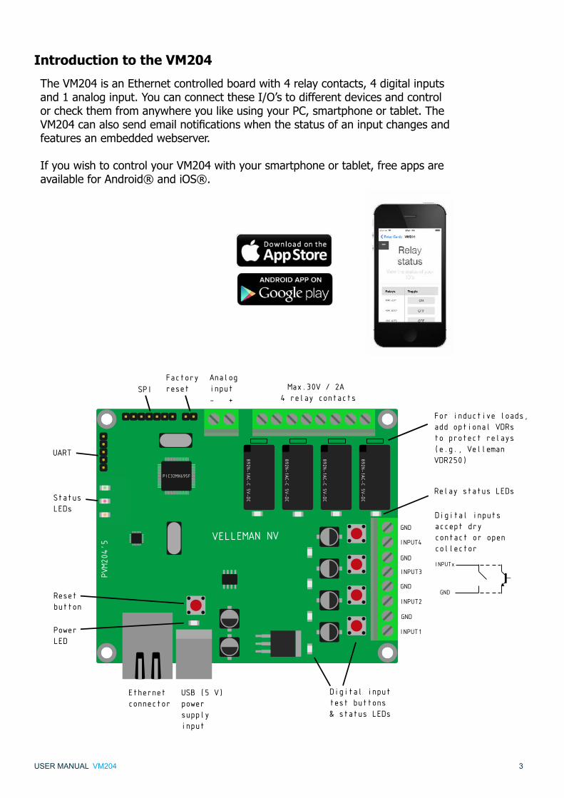
Introduction to the VM204
The VM204 is an Ethernet controlled board with 4 relay contacts, 4 digital inputs and 1 analog input. You can connect these I/O’s to different devices and control or check them from anywhere you like using your PC, smartphone or tablet. The VM204canalsosendemailnotificationswhenthestatusofaninputchangesandfeatures an embedded webserver.
If you wish to control your VM204 with your smartphone or tablet, free apps are available for Android® and iOS®.
Max.30V / 2A 4 relay contacts
Analog input- +
Factory resetSPI
UART
StatusLEDs
Resetbutton
PowerLED
Ethernetconnector
USB (5 V) power supplyinput
PVM204’5
VELLEMAN NV
892N-1AC-C 5V-DC
892N-1AC-C 5V-DC
892N-1AC-C 5V-DC
892N-1AC-C 5V-DC
PIC32MX695F
GND
INPUT4
INPUT3
INPUT2
INPUT1
GND
GND
GND
Relay status LEDs
For inductive loads, add optional VDRs to protect relays (e.g., Velleman VDR250)
Digital inputs accept dry contact or open collector
INPUTx
GND
Digital inputtest buttons & status LEDs
4VM204USER MANUAL
First of all make sure you have a DHCP enabled network. If you don’t know what DHCP is then don’t worry, a regular home network is usually DHCP enabled.
uPleasemakesuretoupgradeyourfirmwaretoversion1.1.Downloadhere:http://www.vellemanprojects.eu/support/downloads/?code=VM204Pleaseseesection4oftheusermanualformoreinformationonupgradingthefirmware.
Connect both the Ethernet cable and the USB cable into the VM204. Afterwards, connect the Ethernet cable to your router and the USB cable to a USB power plug or USB port. The red and yellow LEDs should now be blinking. If the green led is on, you can pro-ceed to the next instruction.
Tocontinue,downloadtheiOS-orAndroidappviathelinksbelow:iOS:www.appstore.com/vm204Android:https://play.google.com/store/apps/details?id=be.velleman.VM204
OrinstallthePCapplicationviathelinkbelow:http://www.velleman.eu/downloads/files/downloads/vm204setup.zip
1. Connecting the Ethernet relay card or VM204
1.1 Using the iOS and Android app for the first time
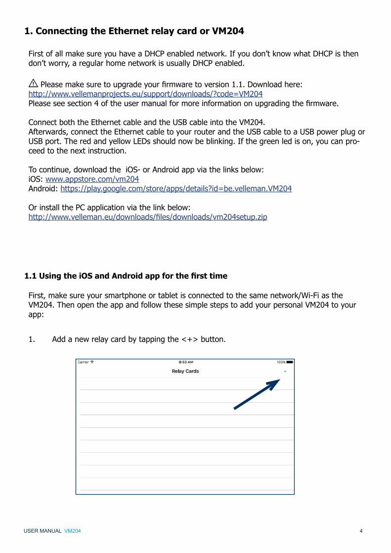
First, make sure your smartphone or tablet is connected to the same network/Wi-Fi as the VM204. Then open the app and follow these simple steps to add your personal VM204 to your app:
1. Add a new relay card by tapping the <+> button.

5VM204USER MANUAL
2. Tap the <scan> button below to search for your VM204.
3. Your VM204 should pop up in the list, be sure to select it.
6VM204USER MANUAL
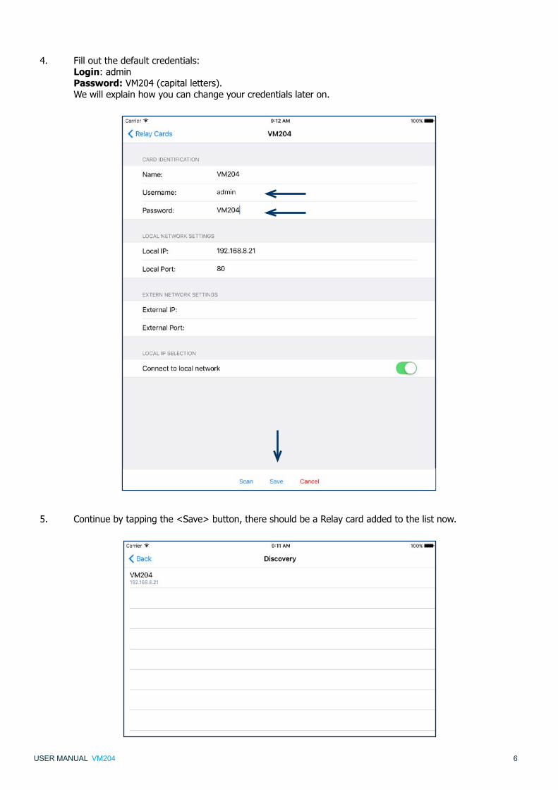
4. Filloutthedefaultcredentials: Login:admin Password: VM204 (capital letters). We will explain how you can change your credentials later on.
5. Continue by tapping the <Save> button, there should be a Relay card added to the list now.
7VM204USER MANUAL
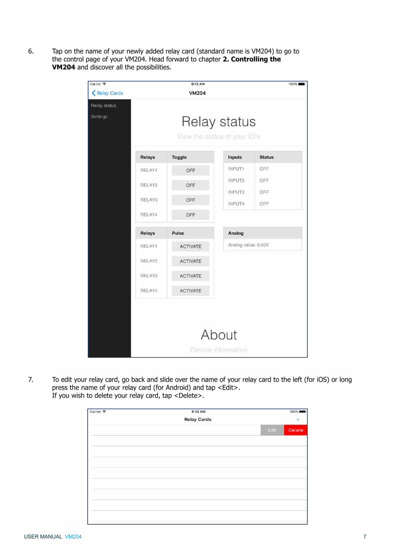
6. Tap on the name of your newly added relay card (standard name is VM204) to go to the control page of your VM204. Head forward to chapter 2. Controlling the VM204 and discover all the possibilities.
7. Toedityourrelaycard,gobackandslideoverthenameofyourrelaycardtotheleft(foriOS)orlong press the name of your relay card (for Android) and tap <Edit>. If you wish to delete your relay card, tap <Delete>.

8VM204USER MANUAL
1.2 Using the PC application for the first time
If you choose to use your PC to control the VM204, make sure your PC is connected to the same network/Wi-Fi as theVM204.ThenopentheVM204discoveryapplicationandfollowthesesimplestepstoconnectyourVM204:
1. Click the <Discover Devices> button.
2. A new row will be added. Click on your device and a webpage should open.
3. Filloutthedefaultcredentials: Login:admin Password: VM204 (capital letters). We will explain how you can change your credentials later on.

9VM204USER MANUAL
4. You now have access to the VM204 and will be able to control it. Head to the next chapter to discover the possibilities.
10VM204USER MANUAL
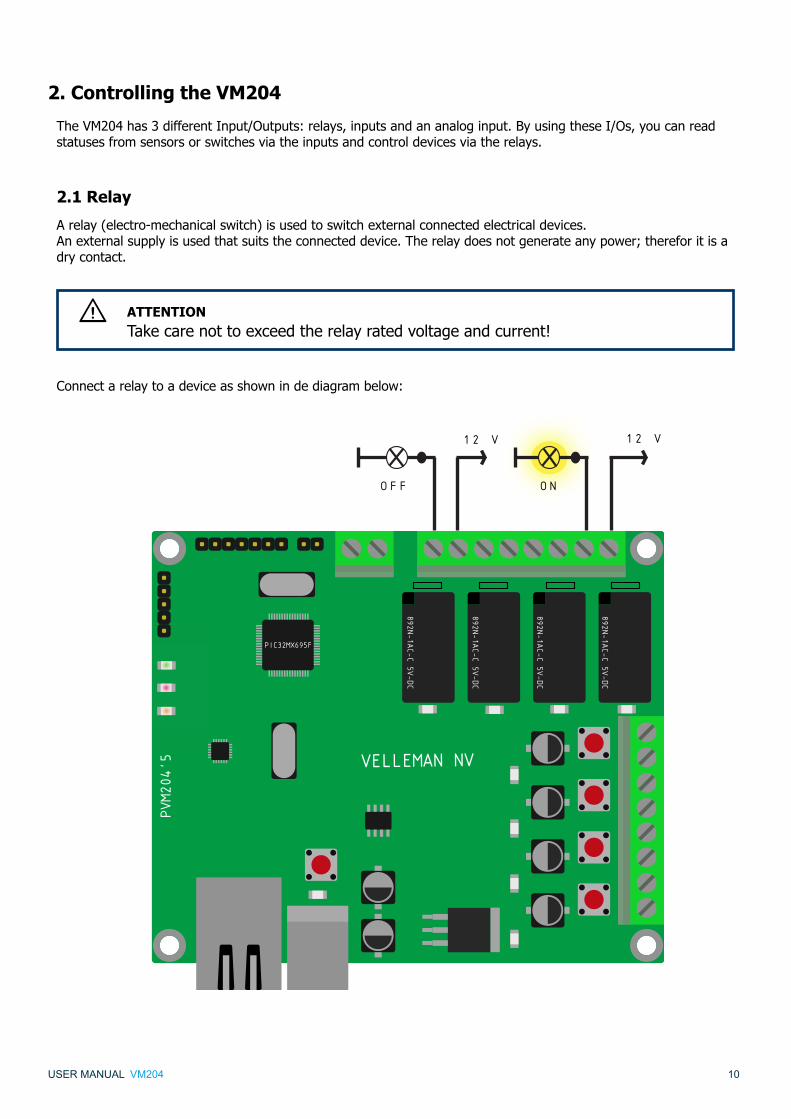
2. Controlling the VM204
TheVM204has3differentInput/Outputs:relays,inputsandananaloginput.ByusingtheseI/Os,youcanreadstatuses from sensors or switches via the inputs and control devices via the relays.
2.1 Relay
A relay (electro-mechanical switch) is used to switch external connected electrical devices.An external supply is used that suits the connected device. The relay does not generate any power; therefor it is a dry contact.
ATTENTION Take care not to exceed the relay rated voltage and current! u
Connectarelaytoadeviceasshownindediagrambelow:
PVM204’5 VELLEMAN NV
892N-1AC-C 5V-DC
892N-1AC-C 5V-DC
892N-1AC-C 5V-DC
892N-1AC-C 5V-DC
PIC32MX695F
12 V12 V
OFF ON

11VM204USER MANUAL
Controlling the relay
You can control the relays you connected via the Main page of your control panel by tapping/clicking on the <OFF> or <ON> button.
The toggle buttons represent the current state of the relay. This means that if you see ON in the button, the relay is closed and is passing through current. If the button says OFF the relay is open and is not passing any current.
2.2 Input
Inputs are used to sense whether 2 terminals are connected to each other or not. These digital inputs accept dry contact or open collector.
PVM204’5 VELLEMAN NV
892N-1AC-C 5V-DC
892N-1AC-C 5V-DC
892N-1AC-C 5V-DC
892N-1AC-C 5V-DC
PIC32MX695F
BUTTON
ATTENTION Do not connect external voltage to the inputs because this will destroy the VM204! u
If the 2 wires are not connected, the status of the input will be OFF, if the 2 wires are connected the status of the input will be ON.
12VM204USER MANUAL
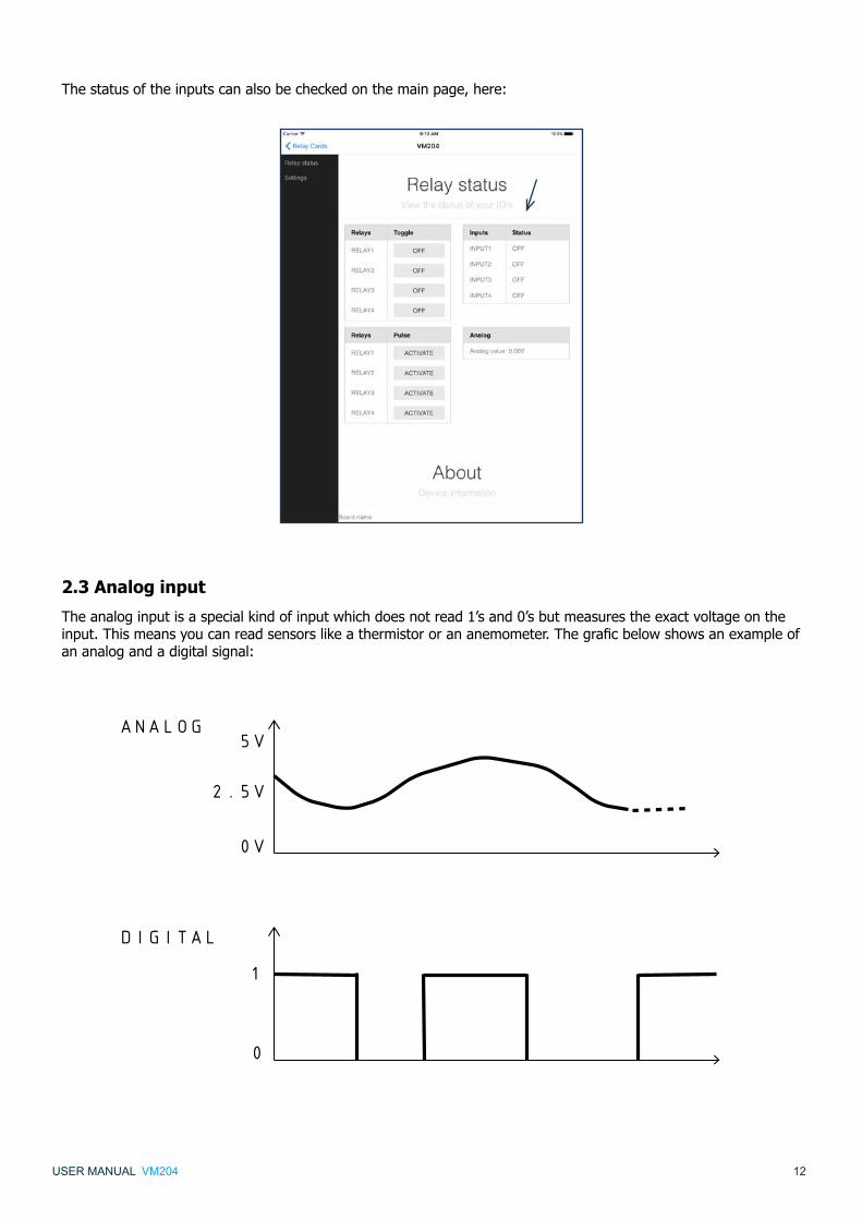
Thestatusoftheinputscanalsobecheckedonthemainpage,here:
2.3 Analog input
The analog input is a special kind of input which does not read 1’s and 0’s but measures the exact voltage on the input.Thismeansyoucanreadsensorslikeathermistororananemometer.Thegraficbelowshowsanexampleofananalogandadigitalsignal:
ANALOG
DIGITAL
0
1
0V
2.5V
5V

13VM204USER MANUAL
Theanalogvaluecanbereadfromthemainpage,here:
2.4 API (Application Programming Interface)
The VM204 has an API which makes it easier for developers to control the relay card from their own application. The complete reference for accessing the API calls can be found in ‘Settings’ and then ‘API Reference’.
2.5 Factory reset
Toreturntothedefaultsettings,followthesesteps:
1. First, make sure the power of the card is on (the yellow and red LEDs should be on).
2. Place a shunt (not incl.) on the factory reset pins (2 pins) next to the analog input. If you do not have a shunt, short the two pins with a conductive piece of metal/wire.
3. Unplug the USB cable (the yellow and red LEDs should now be off).
4. Remove the blue shunt or conductive piece.
5. Plug the USB cable back in.
PVM204’5 VELLEMAN NV
892N-1AC-C 5V-DC
892N-1AC-C 5V-DC
892N-1AC-C 5V-DC
892N-1AC-C 5V-DC
PIC32MX695F
12 V12 V
OFF ON
Make sure you follow the correct order!

14VM204USER MANUAL
3. Editing the VM204
To start editing the VM204, go to ‘Settings’ in the left menu bar.
3.1 Credentials
WARNING changing the credentials will reboot the VM204 and all relays will be deactivated, make sure no machines are connected while doing this!
u
IfyouwanttocontroloredittheVM204,youmustfirstbeauthenticated.ThedefaultLoginandpasswordarestill:Login: adminPassword: VM204 (capitals)
If you want to change the credentials go to ‘Settings’ then ‘Authentication’. Fill out the form and click or tap <save and reboot>.
3.2 Network settings
Ingeneral,thenetworksettingsaresetuptosuityourconvenienceandcanremainunadjusted.Ifhoweveryouareanexperienceduser,wecreatedanopportunityforyoutoadjustthenetworkconfigurationoftheVM204.
If you want to change the port* which the webserver is running on, you can change it by going to ‘Settings’ and then ‘Network’. Now you can enteranewportinthewebinterfacesubsection.Clickortap<Saveandreboot>tofinalise.
WARNING If you click the save and reboot button, the VM204 will deactivate all relays. The webserver will restart with the new port and/or IP so the current webpage will not work. Browse to the new page with the correct port and/or IP.
u

15VM204USER MANUAL
3.3 Email settings
The VM204 is capable of sending emails even with SSL/TLS encryption. This makes the VM204 compatible with Gmail, Outlook, etc... In the email settings, you can enter the email address from which emails will be sent via the VM204.
Go to ‘Settings’ in the left menu bar and scroll down to the Email section. Fill out the credentials of your ISP or any webmailserviceandpress<Save>tofinalise.You can test your credentials by clicking <Test mail settings>. This will send an email to the address that has been savedintotheVM204.Ifeverythingisfilledoutcorrectly,youwillreceiveanemailsaying“Ifyoureceivedthismail, everything is OK”.

16VM204USER MANUAL
3.4 IO settings
ItispossibletocustomizetheIOnames,setthePulsetimeoftheRelays,customizethelookandfeelandeven the functionality of the website.
Changing the IO names
ThenameoftheVM204andalltherelaysandinputscanbechangedbygoingto‘Settings’,‘Customize’andthenfilloutanewnameinthenamefieldofeitherthecardname,relaysorinputs(bluearrows).Don’tforgetto click <Save> when you are done. AspecificcardnamemakesiteasytobrowsetotherelaycardinyourlocalnetworkwithoutrememberingtheIP address. It also makes it easy to distinguish multiple cards in the same network.
If you give each relay and input a different name, it’s easy to remember what the relay is controlling or what the input is reading. For example ‘lights bathroom’ or ‘doorbell’. These names will also be used when sending e-mails from the VM204.
Set the Pulse time
Anothercustomizablefeatureisactivatingtherelaysforacertainamountoftime.Thisisthepulsefeature.Thelength of the pulse can be set in the ‘Pulse’ section using seconds (as shown in the picture above, red arrow).
ACTIVATE PULSE
ACTIVATE PULSE
TIME
TIME
END
END
ON
ON
OFF
OFF
Thepulsecanworkintwoways:
Thefirstway,asshowninthefirstdiagramiswhen you activate the pulse when the relay was in the OFF state. The relay will be in the ON state for the amount of time that you have set.
The second way is when you activate the pulse while the relay is already in the ON state. The relay will remain in the ON state for the amount of time that you have set.

17VM204USER MANUAL
The look, feel and functionality
ThetwonextfieldsintheCustomsectionare‘Customjs’and‘Customcss’.TheyallowyoutoaddaURLtoJavas-criptoraCSSfile,whichcanalterthelooksandfunctionalityofthewebsite.
3.5 Notifications
The‘Notification’settingsallowyoutoenableanddisableemailnotificationsfordifferentactions.When an action is triggered an e-mail will be sent from the account you gave up in your email settings.
Firstmakesureyouenterthecorrectemailaddressestowhichyouwanttosendthenotifications(bluearrow).Ifyouwanttoentermorethenoneemailaddress,typea‘;’inbetweentheaddresseswithnospaces.Forexample:[email protected];[email protected];[email protected],simplyuncheckthe‘Enabled’box(redarrow).Don’tforgettosave!
Actions
Thereare4differentactionstowhichyoucanenableanemailnotification.Youcanchooseoneormoreactionsbyopeningthenotificationlist(asshowninthepicture)andselectingtheactionsyouwanttogetnotifiedof.
We will now explain each action in detail.

18VM204USER MANUAL
A.Inputrising:
An email will be sent if the corresponding Input transfers from a low to a high (or from off to on) state. Forexample:whenthedoorbellgoesoff.Thiscanbedoneforeachindividualinput.
TIME
ON
OFF
OFF = OPEN
ON = CLOSED
OFF = OPEN
B.Inputfalling:
An email will be sent if the corresponding Input transfers from a high to a low (or from on to off) state. Forexample:whentheheatingisturnedoff.Thiscanbedoneforeachindividualinput.
TIME
ON
OFF
OFF = OPEN
ON = CLOSED
OFF = OPEN

19VM204USER MANUAL
C.Boot:
When the VM204 is powered upandhasanIP,thecardwillsendane-mailnotifyingyouitstartedup.Forexample:when the power is rebooted after a power failure.
D.Analogthreshold:
When the analog value reaches a specified value, it will send an email. If the analog value goes below the threshold andthenabove,itwillsendanemailagain.Forexample:ifthetemperatureoutsidedropsbelow0C°.Theanalogtreshold is in this case 0.
TIMEEMAIL
ANALOG TRESHOLD
TEMPERATURE
Analog treshold reached = email
You can set the analog treshold value in the ‘Alarm value’ box after you select this action in the list (see picture below).The alarm value must be between 1 and 1024. This value can be calculated by multiplying your voltage value times155.Forexampleifyourvoltagevalueis3.3Vthenthecalculationis:3.3V*155=511.5=>512.Floating-point numbers are not valid so round your value up or down. The maximum voltage that can be sensed is 6.6 V (=1024).

20VM204USER MANUAL
3.6 API
The API key allows the user to login to the relay card without the credentials but with only a single key. This key is only valid when accessing the API urls that can be found in the API Reference page which will help you to control the relay card from your own programme.
3.7 API reference
The API reference shows you a list of all commands and requests that can be made with your own programme.
This section shows you the device information such as Board name, MAC address, System up-time, Firmware version, Analog max. value and Analog min. value.
3.8 About

21VM204USER MANUAL
4. Upgrading the firmware
IncasethereisnewfirmwareavailableorifthereshouldbeanyproblemswithyourEthernetrelaycard,youcanalwaysreinstall/upgradethefirmwarebyfollowingthesesteps.
1. Beforewestart,itisimportanttocopy/remember/noteyourIPaddressforlateron.Youcanfindthiseither in the ‘settings’ page of the VM204 app or in the IP column in the discovery software. You won’t be able to do this after step 3.
2. GotothedownloadpageoftheVM204ontheVellemanwebsite: http://www.velleman.eu/support/downloads/?code=VM204
Download the ‘VM204 Firmware V1.1’.
3. Mount a shunt onto the factory reset pins (2 pins), located next to the analog input. If you do not have a shunt, short the two pins with a conductive piece of metal/wire.
PVM204’5 VELLEMAN NV
892N-1AC-C 5V-DC
892N-1AC-C 5V-DC
892N-1AC-C 5V-DC
892N-1AC-C 5V-DC
PIC32MX695F
12 V12 V
OFF ON
4. PowercyclethecardbyfirstunpluggingtheUSBcableandtheninsertingitagain.

22VM204USER MANUAL
5. HopefullyyourememberedyourIPaddress!Copyitintothe‘IPAddress’fieldandpress<Connect>. Normally, you should see ‘device connected’.
5. Open the VM204 FW application which is included in the VM204 PC software. You can download this PC softwareontheproductpagehere:
http://www.velleman.eu/support/downloads/?code=VM204
6. Press<LoadHexFile>andopentheHexfileyoudownloadedduringstep2.

23VM204USER MANUAL
7. Press<Erase-Program-Verify>,thiswillfirstreprogramtheVM204andthenrestartit.

VELLEMAN nv - Legen Heirweg 33, Gavere (Belgium)vellemanprojects.com
VellemanProjects @Velleman_RnD
ORDERCODE:VM204
REVISION:HVM204’1