user manual - award-winning pro av manufacturerk.kramerav.com/downloads/manuals/swm-1.pdf · swm-1...
TRANSCRIPT
KRAMER ELECTRONICS LTD.
USER MANUAL
MODEL:
SWM-1 Loudspeaker Wall Mount Device
P/N: 2900-300089 Rev 1
SWM-1 – Contents i
Contents
1 Introduction 1 2 Getting Started 2 3 Overview 3 4 Defining the SWM-1 Loudspeaker Wall Mount Device 4 4.1 Wall Mount Parts 4 4.2 The Loudspeaker Interface Kit 5 4.3 The Wall Fixing Kit 5 5 Installing the SWM-1 6 5.1 Preparing for Installation 6 5.2 Attach the Ball Interface to the Loudspeaker Rear Panel 6 5.3 Attaching the Ball Clamps 8 5.4 Wall Mounting the SWM-1 9 5.5 Mounting the Loudspeaker on the Wall 10 6 Technical Specifications 11
Figures
UFigure 1: SWM-1 Parts per UnitU 4 UFigure 2: Attaching the Ball ClampsU 8 UFigure 3: SWM-1 Assembled KitU 8 UFigure 4: Mounting the Wall Plate on a Concrete WallU 9 UFigure 5: Mounting the Wall Plate on a Wooden WallU 9 UFigure 6: Mounting the LoudspeakerU 10 UFigure 7: Setting the Loudspeaker PositionU 10
SWM-1 - Introduction 1
1 Introduction
Welcome to Kramer Electronics! Since 1981, Kramer Electronics has been
providing a world of unique, creative, and affordable solutions to the vast range of
problems that confront the video, audio, presentation, and broadcasting
professional on a daily basis. In recent years, we have redesigned and upgraded
most of our line, making the best even better!
Our 1,000-plus different models now appear in 11 groups that are clearly defined
by function: GROUP 1: Distribution Amplifiers; GROUP 2: Switchers and Matrix
Switchers; GROUP 3: Control Systems; GROUP 4: Format/Standards Converters;
GROUP 5: Range Extenders and Repeaters; GROUP 6: Specialty AV Products;
GROUP 7: Scan Converters and Scalers; GROUP 8: Cables and Connectors;
GROUP 9: Room Connectivity; GROUP 10: Accessories and Rack Adapters and
GROUP 11: Sierra Products.
Congratulations on purchasing your Kramer SWM-1 Loudspeaker Wall Mount
Device, which is ideal for mounting on-wall loudspeakers.
2 SWM-1 - Getting Started
2 Getting Started
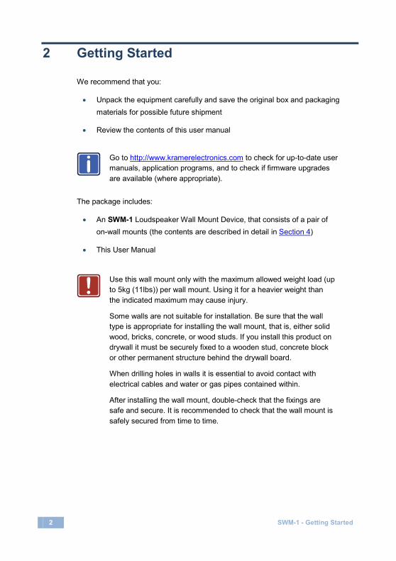
We recommend that you:
• Unpack the equipment carefully and save the original box and packaging materials for possible future shipment
• Review the contents of this user manual
Go to http://www.kramerelectronics.com to check for up-to-date user manuals, application programs, and to check if firmware upgrades are available (where appropriate).
The package includes:
• An SWM-1 Loudspeaker Wall Mount Device, that consists of a pair of on-wall mounts (the contents are described in detail in Section 4
• This User Manual
)
Use this wall mount only with the maximum allowed weight load (up to 5kg (11lbs)) per wall mount. Using it for a heavier weight than the indicated maximum may cause injury.
Some walls are not suitable for installation. Be sure that the wall type is appropriate for installing the wall mount, that is, either solid wood, bricks, concrete, or wood studs. If you install this product on drywall it must be securely fixed to a wooden stud, concrete block or other permanent structure behind the drywall board.
When drilling holes in walls it is essential to avoid contact with electrical cables and water or gas pipes contained within.
After installing the wall mount, double-check that the fixings are safe and secure. It is recommended to check that the wall mount is safely secured from time to time.
i
!
SWM-1 - Overview 3
3 Overview
The Kramer SWM-1 is a versatile device for wall-mounting loudspeakers.
The SWM-1:
• Is designed for cabinet loudspeakers weighing up to 5kg (11lbs)
• Mounts the loudspeaker 72mm (2.8”) from the wall
• Is suitable for single point, dual point and keyhole fixings
• Distance between dual point fixings is 51mm – 67mm (2” – 2.6”)
• Is suitable for loudspeakers using M5, M6, UNC ¼” and wood screws
• Kit includes all the mounting hardware for easy installation
4 SWM-1 - Defining the SWM-1 Loudspeaker Wall Mount Device
4 Defining the SWM-1 Loudspeaker Wall Mount Device Each SWM-1 package includes a pair of loudspeaker wall mounts. The following
sections define the parts of one (of two) wall mount kit.
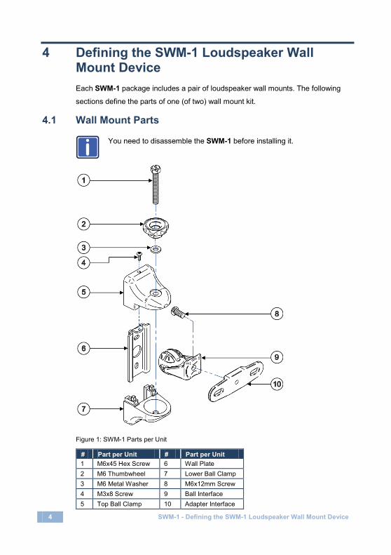
4.1 Wall Mount Parts
You need to disassemble the SWM-1 before installing it.
Figure 1: SWM-1 Parts per Unit
# Part per Unit # Part per Unit 1 M6x45 Hex Screw 6 Wall Plate 2 M6 Thumbwheel 7 Lower Ball Clamp 3 M6 Metal Washer 8 M6x12mm Screw 4 M3x8 Screw 9 Ball Interface 5 Top Ball Clamp 10 Adapter Interface
i

SWM-1 - Defining the SWM-1 Loudspeaker Wall Mount Device 5
4.2 The Loudspeaker Interface Kit
The loudspeaker interface screws are used to attach the wall mount to the
loudspeaker. Use the screws in the kit that fit the hole threading on the
loudspeakers.
# Part per Unit A M5x12mm Screw (2) B M6x12mm Screw (2) C UNC 1/4”x5/8” Screw (2) D M4.2x19mm (No.8x3/4”) Wood Screw (2) E Keyhole insert (1)
4.3 The Wall Fixing Kit
Use the wall fixing screws and wall plugs to fix the wall mount with the
loudspeaker to the wall.
# Parts per Unit A1 M4.8x32mm Wood Screw (2) A2 No6 Wall Plug, for part A1 (2)

6 SWM-1 - Installing the SWM-1
5 Installing the SWM-1
This section describes how to install the SWM-1.
The following instructions refer to the installation of one unit.
5.1 Preparing for Installation
Before installing the loudspeakers, check that you have all the required tools:
• Crosshead/Flathead screwdriver
• Power drill
• 6mm (1/4") masonry bit or 3mm (1/8") wood bit
• Pencil
• Level and stud finder (optional)
5.2 Attach the Ball Interface to the Loudspeaker Rear Panel
This section describes several methods in which you can attach the SWM-1 Ball
Interface to the rear side of the loudspeaker. Choose the method that fits best to
your loudspeaker:
One Insert: Connect the ball interface to the single hole on the loudspeaker rear panel using screw types A, B or C (see Section 4.2
).
i
SWM-1 - Installing the SWM-1 7
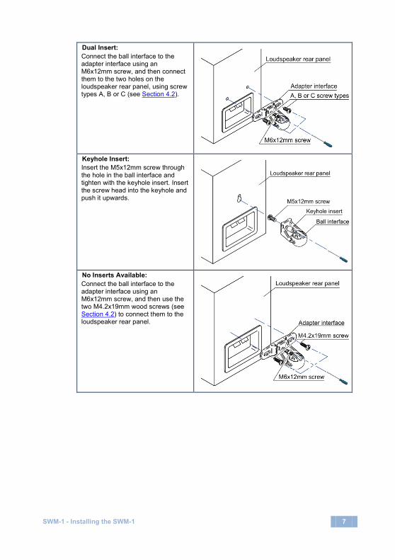
Dual Insert: Connect the ball interface to the adapter interface using an M6x12mm screw, and then connect them to the two holes on the loudspeaker rear panel, using screw types A, B or C (see Section 4.2
).
Keyhole Insert: Insert the M5x12mm screw through the hole in the ball interface and tighten with the keyhole insert. Insert the screw head into the keyhole and push it upwards.
No Inserts Available: Connect the ball interface to the adapter interface using an M6x12mm screw, and then use the two M4.2x19mm wood screws (see Section 4.2
) to connect them to the loudspeaker rear panel.
8 SWM-1 - Installing the SWM-1
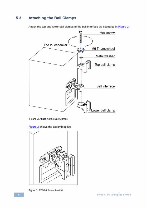
5.3 Attaching the Ball Clamps
Attach the top and lower ball clamps to the ball interface as illustrated in Figure 2:
Figure 2: Attaching the Ball Clamps
Figure 3 shows the assembled kit:
Figure 3: SWM-1 Assembled Kit

SWM-1 - Installing the SWM-1 9
5.4 Wall Mounting the SWM-1
You can mount the SWM-1 either on a brick or concrete wall or wood/wood stud
walls.
To mount on a concrete or brick wall, as shown in Figure 4, use a 6mm (1/4”)
masonry bit with your drill:
Figure 4: Mounting the Wall Plate on a Concrete Wall
To mount on a wooden wall or stud, as shown in Figure 5, use a 3mm (1/8”) wood
bit with your drill (you can use a stud finder to find the wooden stud):
Figure 5: Mounting the Wall Plate on a Wooden Wall

10 SWM-1 - Installing the SWM-1
5.5 Mounting the Loudspeaker on the Wall
To mount the loudspeaker on the wall, slide the assembly onto the wall plate and
secure with the M3x8mm screw, as shown in Figure 6:
Figure 6: Mounting the Loudspeaker
To set the position of the loudspeaker, loosen the thumbwheel (or the top hex
screw), set the loudspeaker at the desired angle and then retighten, as shown in
Figure 7:
Figure 7: Setting the Loudspeaker Position
SWM-1 - Technical Specifications 11
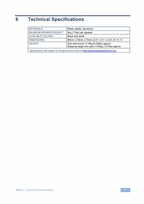
6 Technical Specifications
MATERIALS: Metal, plastic, aluminum MAXIMUM SPEAKER WEIGHT: 5kg (11lbs) per speaker AVAILABLE COLORS: Black and white DIMENSIONS: 88mm x 79mm x 72mm (3.5” x 3.1” x 2.8”), W, D, H WEIGHT: One wall mount: 0.19kg (0.42lbs) approx.
Shipping weight (for pair): 0.55kg (1.21lbs) approx.
Specifications are subject to change without notice at http://www.kramerelectronics.com

12 SWM-1 - Technical Specifications
LIMITED WARRANTY
WHO IS PROTECTED?
WHAT IS COVERED AND WHAT IS NOT COVERED
WHAT WE WILL PAY FOR AND WHAT WE WILL NOT PAY FOR
HOW YOU CAN GET WARRANTY SERVICE
LIMITATION OF IMPLIED WARRANTIES
EXCLUSION OF DAMAGES
CAUTION!
We warrant this product free from defects in material and workmanship under the following terms.HOW LONG IS THE WARRANTYLabor and parts are warranted for one year from the date of the first customer purchase.
Only the first purchase customer may enforce this warranty.
We will pay labor and material expenses for covered items. We will not pay for the following:
The liability of Kramer for any effective products is limited to the repair or replacement of the product at our option. Kramer shall not be liable for:
This warranty gives you specific legal rights, and you may also have other rights, which vary from place to place.: All products returned to Kramer for service must have prior approval. This may be obtained from your dealer.
This equipment has been tested to determine compliance with the requirements of:
EN-50081: "Electromagnetic compatibility (EMC);generic emission standard.
Residential, commercial and light industry"EN-50082: "Electromagnetic compatibility (EMC) generic immunity standard.
Part 1: Residential, commercial and light industry environment".CFR-47: FCC* Rules and Regulations:
Part 15: “Radio frequency devicesSubpart B Unintentional radiators”
Except as below, this warranty covers all defects in material or workmanship in this product. The following are not covered by the warranty:1. Any product which is not distributed by us or which is not purchased from an authorized Kramer dealer. If you are
uncertain as to whether a dealer is authorized, please contact Kramer at one of the agents listed in the Web site www.kramerelectronics.com.
2. Any product, on which the serial number has been defaced, modified or removed, or on which the WARRANTY VOID TAMPERED sticker has been torn,
3. Damage, deterioration or malfunction resulting from:i) Accident, misuse, abuse, neglect, fire, water, lightning or other acts of natureii) Product modification, or failure to follow instructions supplied with the productiii) Repair or attempted repair by anyone not authorized by Krameriv) Any shipment of the product (claims must be presented to the carrier)v) Removal or installation of the productvi) Any other cause, which does not relate to a product defectvii) Cartons, equipment enclosures, cables or accessories used in conjunction with the product
1. Removal or installations charges.2. Costs of initial technical adjustments (set-up), including adjustment of user controls or programming. These costs are
the responsibility of the Kramer dealer from whom the product was purchased.3. Shipping charges.
1. To obtain service on you product, you must take or ship it prepaid to any authorized Kramer service center.2. Whenever warranty service is required, the original dated invoice (or a copy) must be presented as proof of
warranty coverage, and should be included in any shipment of the product. Please also include in any mailing a contact name, company, address, and a description of the problem(s).
3. For the name of the nearest Kramer authorized service center, consult your authorized dealer.
All implied warranties, including warranties of merchantability and fitness for a particular purpose, are limited in duration to the length of this warranty.
1. Damage to other property caused by defects in this product, damages based upon inconvenience, loss of use of the product, loss of time, commercial loss; or:
2. Any other damages, whether incidental, consequential or otherwise. Some countries may not allow limitations on how long an implied warranty lasts and/or do not allow the exclusion or limitation of incidental or consequential damages, so the above limitations and exclusions may not apply to you.
Servicing the machines can only be done by an authorized Kramer technician. Any user who makes changes or modifications to the unit without the expressed approval of the manufacturer will void user authority to operate the equipment.Use the supplied DC power supply to feed power to the machine.Please use recommended interconnection cables to connect the machine to other components.
IF reattached, removed or otherwise interfered with.
* FCC and CE approved using STP cable (for twisted pair products)
NOTE
Part 1:

For the latest information on our products and a list of Kramer distributors, visit our Web site where updates to this user manual may be found.
We welcome your questions, comments, and feedback. Web site: E-mail:
www.kramerelectronics.com
! SAFETY WARNINGDisconnect the unit from the powersupply before opening and servicing