user manual 03/2003 edition - tu · pdf file2.1.1 node address ... 4.2.5 measuring steps per...
TRANSCRIPT

User Manual 03/2003 Edition
Absolute Value Encoder with PROFIBUS-DPSIMODRIVE sensor


General Information 1
Installation 2
Device Configuration 3
Class 1 and Class 2 4
Encoder Classes,Version 2.1 and 2.2
5
Diagnostic Messages 6
Configuration ExampleSTEP 7 7
DPV2 Functionality-General Information
8
Data TransferIsochronous Operation
9
ParameterizingIsochronous Operation
10
Non-Cyclic Utilities 11
Fault Signals/Diagnostics
12
Configuring Examplefor Isochr. Operation
13
Technical Data 14
Appendix 15
Index 16
SIMODRIVE sensor
Absolute Value Encoder withPROFIBUS-DPUser Manual
Valid for
Product VersionSIMODRIVE sensor Firmware version 2.0
03/03 Edition

SINUMERIK® Documentation
Printing history
Brief details of this edition and previous editions are listed below.
The status of each edition is shown by the code in the „Remarks“ column.
Status code in the „Remarks" column:
A .... New documentation.B .... Unrevised reprint with new Order No.C .... Revised edition with new status.
If factual changes have been made on the page within the same software version, this is indicated by anew edition coding in the header on that page.
Edition Order No. Remarks05/9702/99
6SN1197-0AB10-0YP06SN1197-0AB10-0YP1
AC
03/03 6SN1197-0AB10-0YP2 C
This manual is included in the documentation on CD-ROM (DOCONCD)Edition Order No. Remarks09/03 6FC5298-6CA00-0BG4 A
TrademarksSIMATIC® , SIMATIC HMI® , SIMATIC NET® , SINUMERIK® and SIMODRIVE® are trademarks of
Siemens. Other product names used in this documentation may be trademarks which, if used by third parties,could infringe the rights of their owners.
Further information is available on the Internet under:http://www.ad.siemens.de/drives
This publication was produced with WinWord V 8.0 and Designer V 7.0and the DokuTool AutWinDoc
The reproduction, transmission or use of this document or its contents isnot permitted without express written authority. Offenders will be liablefor damages. All rights, including rights created by patent grant orregistration of a utility model or design, are reserved.
© Siemens AG 1997 - 2003. All Rights Reserved.
Other functions not described in this documentation might beexecutable in the control. This does not, however, represent anobligation to supply such functions with a new control or whenservicing.
We have checked that the contents of this publication agree with thehardware and software described herein. Nevertheless, differencesmight exist and therefore we cannot guarantee that they are completelyidentical. The information given in this publication is reviewed at regularintervals and any corrections that might be necessary are made in thesubsequent printings. Suggestions for improvement are welcome at alltimes.
Subject to change without prior notice.
Order No. 6SN1197-0AB10-0YP2Printed in the Federal Republic of Germany
Siemens-Aktiengesellschaft.
03/03 SIMODRIVE sensorContents
© Siemens AG 2003 All Rights ReservedSIMODRIVE sensor (BN) - 03/03 Edition v
Contents
General Information.................................................................................................................................1-9
1.1 Absolute value encoders ............................................................................................1-10
1.2 Profibus technology....................................................................................................1-10
Installation..............................................................................................................................................2-11
2.1 Settings in the connecting cover ................................................................................2-132.1.1 Node address .............................................................................................................2-132.1.2 Bus termination ..........................................................................................................2-13
2.2 Connecting-up the signal and power supply cables ...................................................2-15
2.3 Connecting-up the connecting cover ..........................................................................2-16
2.4 Connecting the shielded cable ...................................................................................2-17
2.5 Information on mechanically installing and electrically connecting-up theabsolute value encoder ..............................................................................................2-17
Device configuration .............................................................................................................................3-19
3.1 Overview, data transfer principle ................................................................................3-20
3.2 Overview, functionality of the encoder classes...........................................................3-21
3.3 Overview, data format of the encoder classes ...........................................................3-22
Class 1 and Class 2 ...............................................................................................................................4-23
4.1 Note ......................................................................................................................4-25
4.2 Parameterization ......................................................................................................4-264.2.1 Direction of rotation ....................................................................................................4-274.2.2 Activating/de-activating Class 2 functionality..............................................................4-274.2.3 Activating/de-activating commissioning diagnostics...................................................4-274.2.4 Activating/de-activating the scaling function...............................................................4-274.2.5 Measuring steps per revolution ..................................................................................4-274.2.6 Total resolution...........................................................................................................4-28
4.3 Data transfer in normal operation...............................................................................4-304.3.1 Transferring the process actual value ........................................................................4-304.3.2 Preset function ...........................................................................................................4-30

SIMODRIVE sensor 03/03Contents
© Siemens AG 2003 All Rights Reservedvi SIMODRIVE sensor (BN) - 03/03 Edition
Encoder Classes, Version 2.1 and 2.2 .................................................................................................5-31
5.1 Parameters .................................................................................................................5-335.1.1 Activating the manufacturer-specific parameters .......................................................5-335.1.2 Required measuring steps .........................................................................................5-335.1.3 Resolution reference ..................................................................................................5-345.1.4 Activating the commissioning mode ...........................................................................5-355.1.5 Reduced diagnostics ..............................................................................................5-355.1.6 Software limit switches ..............................................................................................5-365.1.7 Physical measuring steps...........................................................................................5-375.1.8 Absolute value encoder type ......................................................................................5-385.1.9 Dimension units of the velocity...................................................................................5-38
5.2 Data transfer in the normal mode...............................................................................5-39
5.3 The commissioning mode ..........................................................................................5-405.3.1 Setting the direction of rotation...................................................................................5-415.3.2 Starting teach-in .........................................................................................................5-415.3.3 Stopping teach-in .......................................................................................................5-425.3.4 Preset value................................................................................................................5-42
Diagnostic Messages ............................................................................................................................6-43
6.1 Overview.....................................................................................................................6-44
6.2 Diagnostic messages which are supported................................................................6-456.2.1 Expanded diagnostics header ....................................................................................6-456.2.2 Memory errors ............................................................................................................6-456.2.3 Operating state...........................................................................................................6-456.2.4 Encoder type ..............................................................................................................6-456.2.5 Single-turn resolution .................................................................................................6-456.2.6 Number of revolutions ................................................................................................6-466.2.7 Operating time alarm..................................................................................................6-466.2.8 Profile version.............................................................................................................6-466.2.9 Software version.........................................................................................................6-466.2.10 Operating time............................................................................................................6-466.2.11 Zero offset ..................................................................................................................6-466.2.12 Parameterized resolution per revolution.....................................................................6-466.2.13 Parameterized total resolution....................................................................................6-476.2.14 Serial number .............................................................................................................6-47
6.3 Status signals using LEDs in the connecting cover....................................................6-48
Configuration Example STEP 7 ............................................................................................................7-49
7.1 Reading-in the GSD files ............................................................................................7-50
7.2 Configuring the absolute value encoder....................................................................7-51
7.3 Selecting the device class ..........................................................................................7-52
7.4 Parameterization ........................................................................................................7-53

03/03 SIMODRIVE sensorContents
© Siemens AG 2003 All Rights ReservedSIMODRIVE sensor (BN) - 03/03 Edition vii
DPV2 Functionality - General Information ...........................................................................................8-57
8.1 Isochronous operation................................................................................................8-59
8.2 Slave-to-slave communication....................................................................................8-60
Data Transfer Isochronous Operation .................................................................................................9-61
9.1 Run-up........................................................................................................................9-639.1.1 Slave parameterization, configuration ........................................................................9-639.1.2 Synchronizing to the clock cycle Global Control.........................................................9-639.1.3 Synchronizing the slave application to the master sign-of-life....................................9-639.1.4 Synchronizing the master application to the slave sign-of-life character....................9-649.1.5 Cyclic operation..........................................................................................................9-64
9.2 Telegram type 81........................................................................................................9-65
Parameterizing Isochronous Operation.............................................................................................10-67
10.1 Parameter – overview...............................................................................................10-69
10.2 Device-specific parameters ......................................................................................10-7010.2.1 Direction of rotation ..................................................................................................10-7010.2.2 Scaling/preset/counting direction .............................................................................10-7010.2.3 Measuring steps per revolution ................................................................................10-7110.2.4 Total resolution.........................................................................................................10-7110.2.5 Maximum master sign-of-life character failures........................................................10-71
10.3 Isochronous parameters...........................................................................................10-7210.3.1 TBASE_DP ....................................................................................................................10-7210.3.2 TDP ............................................................................................................................10-7210.3.3 TMAPC.........................................................................................................................10-7210.3.4 TBASE_IO .....................................................................................................................10-7210.3.5 TI...............................................................................................................................10-7210.3.6 TO .............................................................................................................................10-7310.3.7 TDX ............................................................................................................................10-7310.3.8 TPLL_W .......................................................................................................................10-7310.3.9 TPLL_D ........................................................................................................................10-73
10.4 Slave-to-slave communication..................................................................................10-74
Non-Cyclic Utilities ..............................................................................................................................11-75
Fault Signals/Diagnostics in Isochronous Operation ......................................................................12-77
12.1 Profibus diagnostics .................................................................................................12-78
12.2 Status signals using the LEDs in the connecting cover............................................12-79
12.3 Fault codes in G1_XIST2 .........................................................................................12-80
Configuring Example for Isochronous Operation – STEP 7 ............................................................13-81
13.1 Reading-in the GSD file............................................................................................13-82
13.2 Configuring the absolute value encoder...................................................................13-83
13.3 Telegram selection ...................................................................................................13-84

SIMODRIVE sensor 03/03Contents
© Siemens AG 2003 All Rights Reservedviii SIMODRIVE sensor (BN) - 03/03 Edition
13.4 Parameterization ......................................................................................................13-8513.4.1 Device-specific parameters ......................................................................................13-8513.4.2 Isochronous parameters...........................................................................................13-86
Technical Data .....................................................................................................................................14-89
14.1 Electrical data...........................................................................................................14-90
14.2 Mechanical data .......................................................................................................14-91
14.3 Ambient conditions ...................................................................................................14-92
14.4 Dimension drawings .................................................................................................14-93
Appendix ..............................................................................................................................................15-95
15.1 Additional encoder classes.......................................................................................15-9615.1.1 Version 2.0 multi-turn ...............................................................................................15-9615.1.2 Version 1.1 multi-turn ...............................................................................................15-9615.1.3 Version 1.0 multi-turn ...............................................................................................15-96
15.2 FAQ Absolute value encoders, Profibus...................................................................15-97
15.3 Terminology..............................................................................................................15-99
Index ...................................................................................................................................................16-101
© Siemens AG 2003 All Rights ReservedSIMODRIVE sensor (BN) - 03/03 Edition 1-9
General Information
1.1 Absolute value encoders ................................................................................1-10
1.2 Profibus technology........................................................................................1-10
1

1 General Information 03/031.1 Absolute value encoders
© Siemens AG 2003 All Rights Reserved1-10 SIMODRIVE sensor (BN) - 03/03 Edition
1.1 Absolute value encodersThis Manual describes the commissioning and configuring of absolute valueencoders with PROBIFUS-DP interface. The device fulfills the requirementsplaced on a Profibus slave in compliance with the Profibus Standard and iscertified by the Profibus User Organization.
The basic principle of operation of the absolute measured value sensing is theoptical scanning of a transparent coding disk which is coupled to the shaft tobe measured. The position of the shaft can be determined by evaluating thecode with a resolution of up to 8192 steps per revolution (13 bit).
For so-called multi-turn devices, other coding disks are coupled through step-down gearing. These subsequently coupled disks allow the number of shaftrevolutions to be determined in absolute terms (up to 4096 revolutions =12 bits).
For absolute value encoders with PROFIBUS-DP, the position value, opticallydetected, is computed in an integrated microprocessor and the data istransferred via Profibus.
1.2 Profibus technologyPROFIBUS is a non-proprietary, open fieldbus Standard which is defined byinternational Standards EN 50170 and EN 50254. There are 3 versions: DP,FMS and PA. SIEMENS absolute value encoders support the DP version andare designed for the usual data transfer rates of up to 12 Mbaud.
In addition to manufacturer-specific functions, the devices support Classes 1and 2 according to the encoder profile. This device profile can be ordered fromthe Profibus User Organization under Order No. 3.062. Additional informationon PROFIBUS can also be obtained from the Profibus User Organization(functionality, manufacturer, products) as well as Standards and profiles:Profibus User OrganizationHaid-und-Neu-Straße 7D-76131 KarlsruheTel: +49 721 / 96 58 590Fax: +49 721 / 96 58 589

© Siemens AG 2003 All Rights ReservedSIMODRIVE sensor (BN) - 03/03 Edition 2-11
Installation
2.1 Settings in the connecting cover ........................................................................2-132.1.1 Node address.....................................................................................................2-132.1.2 Bus termination..................................................................................................2-13
2.2 Connecting-up the signal and power supply cables...........................................2-15
2.3 Connecting-up the connecting cover .................................................................2-16
2.4 Connecting the shielded cable...........................................................................2-17
2.5 Information on mechanically installing and electrically connecting-up theabsolute value encoder......................................................................................2-17
2

2 Installation 03/032.1 Settings in the connecting cover
© Siemens AG 2003 All Rights Reserved2-12 SIMODRIVE sensor (BN) - 03/03 Edition
The absolute value encoder is connected-up through the so-called connectingcover. This is connected to the rotary encoder through a 15-pin D-Sub plugconnector. It can be removed by releasing 2 screws at the rear of the device.Bus and power supply cables are fed into the connecting cover through cableglands and connected to screw terminals.

03/03 2 Installation2.1 Settings in the connecting cover
© Siemens AG 2003 All Rights ReservedSIMODRIVE sensor (BN) - 03/03 Edition 2-13
2.1 Settings in the connecting cover2.1.1 Node address
A decimal rotary switch in the connecting cover is used to set the Profibusnode address. The weighting (x 10 or x 1) is specified at the switch.Permissible addresses lie between 1 and 99, whereby each one must beunique in the complete system. The device address is read-in from theabsolute value encoder when the power supply voltage is switched-on.Address changes by the master ("Set_Slave_Add") are not supported.
28287 7
x10
456
3
x1
456
3
B A
ON
+
19 0
B A
9 0 1
R
+
2.1.2 Bus terminationIf the encoder is connected at the end or beginning of the bus line, theterminating resistor must be switched on (slide switch in position "ON"):
R RON ON
Node X Last node
Note
When the terminating resistor is switched-in, the bus out is de-coupled!

2 Installation 03/032.1 Settings in the connecting cover
© Siemens AG 2003 All Rights Reserved2-14 SIMODRIVE sensor (BN) - 03/03 Edition
The bus has only been correctly terminated if the encoder is mounted to theconnecting cover. If the encoder must be replaced in operation (hot swap),then we recommend that a separate active bus termination is used.
After the address has been set on the hardware side, and where necessary,the cable terminating-resistor switched-in, then the absolute value encoder canbe commissioned.
03/03 2 Installation2.2 Connecting-up the signal and power supply cables
© Siemens AG 2003 All Rights ReservedSIMODRIVE sensor (BN) - 03/03 Edition 2-15
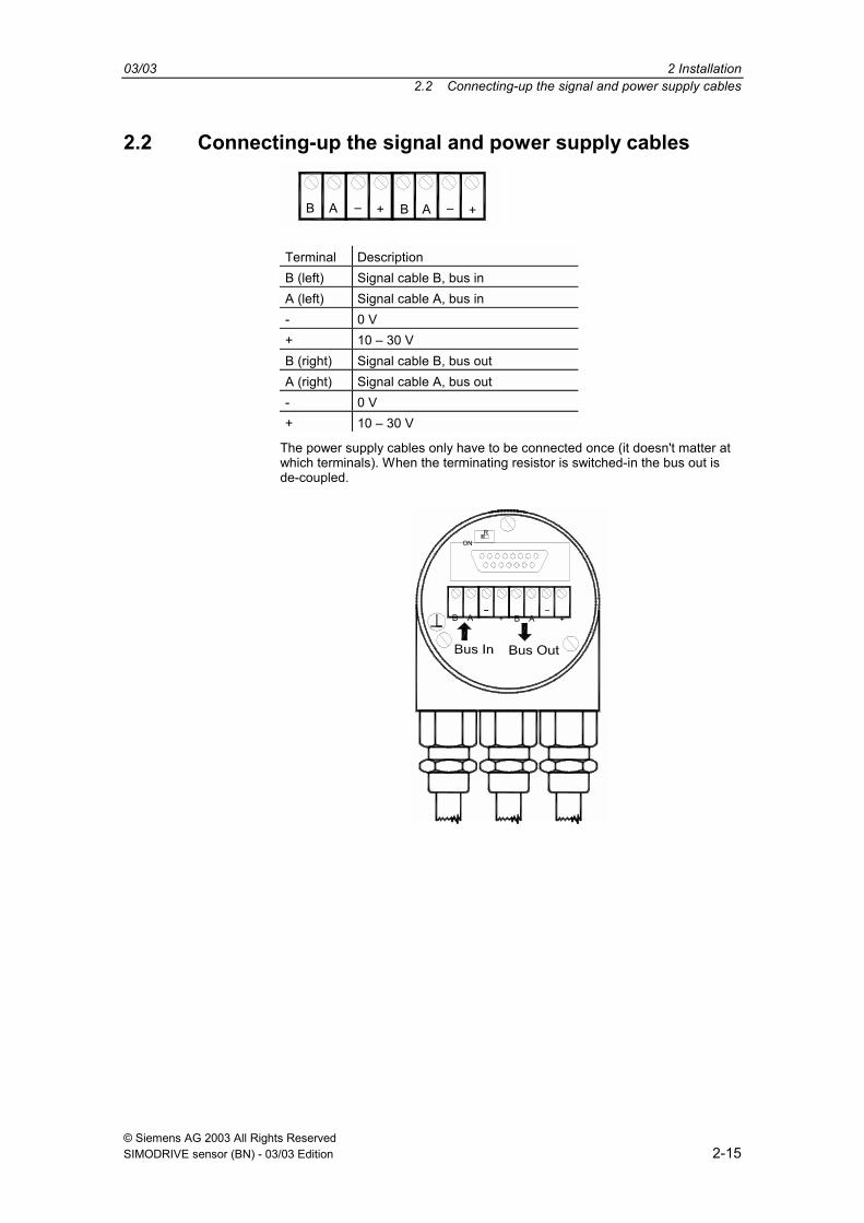
2.2 Connecting-up the signal and power supply cables
AB + B +A
Terminal DescriptionB (left) Signal cable B, bus inA (left) Signal cable A, bus in- 0 V+ 10 30 VB (right) Signal cable B, bus outA (right) Signal cable A, bus out- 0 V+ 10 30 V
The power supply cables only have to be connected once (it doesn't matter atwhich terminals). When the terminating resistor is switched-in the bus out isde-coupled.
ABAB + +
ONR

2 Installation 03/032.3 Connecting-up the connecting cover
© Siemens AG 2003 All Rights Reserved2-16 SIMODRIVE sensor (BN) - 03/03 Edition
2.3 Connecting-up the connecting coverThe pressure screw, insert and taper sleeve must be removed from the cablegland. Approximately 55 mm of the bus cable sheath must be removed andapproximately 50 mm of the braided screen. Approximately 5 mm insulationmust be removed from the individual conductors.
The pressure screw and insert are then threaded onto the cable. The tapersleeve is pushed under the screen as shown in the drawing. The completeassembly is then inserted in the cable gland and the pressure screw tightened.
5 mm 5 mm
55 mm
50 mm
03/03 2 Installation2.4 Connecting the shielded cable
© Siemens AG 2003 All Rights ReservedSIMODRIVE sensor (BN) - 03/03 Edition 2-17
2.4 Connecting the shielded cableIn order to achieve the highest possible noise immunity, shielded cables areused to transfer signals between the system components. The shields of thesecables are connected at both ends. For specific system configurations anequalization current can flow through the cable shield which is connected atboth ends. This is the reason that we recommend a potential bondingconductor.
2.5 Information on mechanically installing and electricallyconnecting-up the absolute value encoder
The following points should be observed:
• Do not drop the absolute value encoder or subject it to excessive vibration.The encoder is a precision device.
• Do not open the absolute value encoder housing (this does not mean thatyou cannot remove the cover). If the device is opened and closed again,then it can be damaged and dirt may enter the unit.
• The absolute encoder shaft must be connected to the shaft to be measuredthrough a suitable coupling. This coupling is used to dampen vibrations andimbalance on the encoder shaft and also avoid inadmissibly high forces.
• Although SIEMENS absolute value encoders are rugged, when used intough ambient conditions, they should be protected against damage usingsuitable protective measures. Care should be taken that they are notinstalled so that they can be used as handles or even steps.
• Only qualified personnel may commission and operate these devices.These are personnel who are authorized to commission, ground and tagdevices, systems and circuits according to the current state of safetytechnology.
• It is not permissible to make any electrical changes to the encoder.
• Route the connecting cable to the absolute value encoder at a considerabledistance away or completely separated from power cables with theirassociated noise. Completely screen cables must be used for reliable datatransfer and good grounding must be provided.
• Cabling, establishing and interrupting electrical connections may only becarried-out when the equipment is in a no-voltage condition. Short-circuits,voltage spikes etc. can result in erroneous functions and uncontrolledstatuses which can even include severe personnel injury and materialdamage.
• Before powering-up the system, check all of the electrical connections.Connections, which are not correct, can cause the system to functionincorrectly and fault connections can result in severe personnel injury andmaterial damage.

2 Installation 03/032.5 Information on mechanically installing and electrically connecting-up the absolute value encoder
© Siemens AG 2003 All Rights Reserved2-18 SIMODRIVE sensor (BN) - 03/03 Edition
Space for your notes
© Siemens AG 2003 All Rights ReservedSIMODRIVE sensor (BN) - 03/03 Edition 3-19
Device Configuration
3.1 Overview, data transfer principle ....................................................................3-20
3.2 Overview, functionality of the encoder classes...............................................3-21
3.3 Overview, data format of the encoder classes ...............................................3-22
3
3 Device Configuration 03/033.1 Overview, data transfer principle
© Siemens AG 2003 All Rights Reserved3-20 SIMODRIVE sensor (BN) - 03/03 Edition
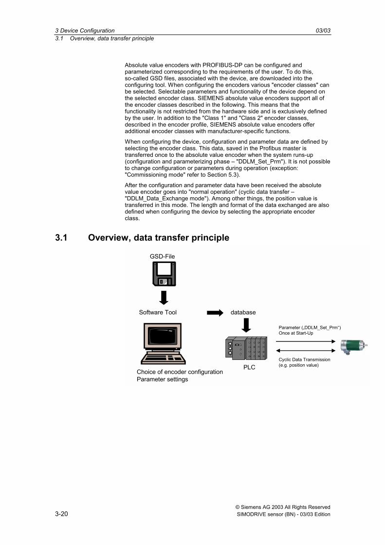
Absolute value encoders with PROFIBUS-DP can be configured andparameterized corresponding to the requirements of the user. To do this,so-called GSD files, associated with the device, are downloaded into theconfiguring tool. When configuring the encoders various "encoder classes" canbe selected. Selectable parameters and functionality of the device depend onthe selected encoder class. SIEMENS absolute value encoders support all ofthe encoder classes described in the following. This means that thefunctionality is not restricted from the hardware side and is exclusively definedby the user. In addition to the "Class 1" and "Class 2" encoder classes,described in the encoder profile, SIEMENS absolute value encoders offeradditional encoder classes with manufacturer-specific functions.
When configuring the device, configuration and parameter data are defined byselecting the encoder class. This data, saved in the Profibus master istransferred once to the absolute value encoder when the system runs-up(configuration and parameterizing phase "DDLM_Set_Prm"). It is not possibleto change configuration or parameters during operation (exception:"Commissioning mode" refer to Section 5.3).
After the configuration and parameter data have been received the absolutevalue encoder goes into "normal operation" (cyclic data transfer "DDLM_Data_Exchange mode"). Among other things, the position value istransferred in this mode. The length and format of the data exchanged are alsodefined when configuring the device by selecting the appropriate encoderclass.
3.1 Overview, data transfer principle
GSD-File
Software Tool database
PLCChoice of encoder configurationParameter settings
Parameter (DDLM_Set_Prm)Once at Start-Up
Cyclic Data Transmission(e.g. position value)
03/03 3 Device Configuration3.2 Overview, functionality of the encoder classes
© Siemens AG 2003 All Rights ReservedSIMODRIVE sensor (BN) - 03/03 Edition 3-21
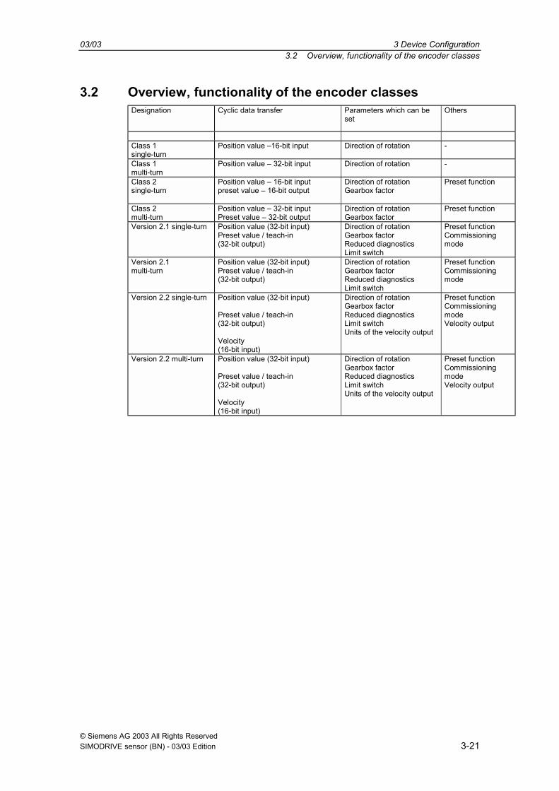
3.2 Overview, functionality of the encoder classesDesignation Cyclic data transfer Parameters which can be
setOthers
Class 1single-turn
Position value 16-bit input Direction of rotation -
Class 1multi-turn
Position value 32-bit input Direction of rotation -
Class 2single-turn
Position value 16-bit inputpreset value 16-bit output
Direction of rotationGearbox factor
Preset function
Class 2multi-turn
Position value 32-bit inputPreset value 32-bit output
Direction of rotationGearbox factor
Preset function
Version 2.1 single-turn Position value (32-bit input)Preset value / teach-in(32-bit output)
Direction of rotationGearbox factorReduced diagnosticsLimit switch
Preset functionCommissioningmode
Version 2.1multi-turn
Position value (32-bit input)Preset value / teach-in(32-bit output)
Direction of rotationGearbox factorReduced diagnosticsLimit switch
Preset functionCommissioningmode
Version 2.2 single-turn Position value (32-bit input)
Preset value / teach-in(32-bit output)
Velocity(16-bit input)
Direction of rotationGearbox factorReduced diagnosticsLimit switchUnits of the velocity output
Preset functionCommissioningmodeVelocity output
Version 2.2 multi-turn Position value (32-bit input)
Preset value / teach-in(32-bit output)
Velocity(16-bit input)
Direction of rotationGearbox factorReduced diagnosticsLimit switchUnits of the velocity output
Preset functionCommissioningmodeVelocity output

3 Device Configuration 03/033.3 Overview, data format of the encoder classes
© Siemens AG 2003 All Rights Reserved3-22 SIMODRIVE sensor (BN) - 03/03 Edition
3.3 Overview, data format of the encoder classesConfiguration(ID)
Description, referto
Designation
Hex Dec.
Input words(AWC-> master)
Output words(master ->AWC) Section Page
Class 1 single-turn(acc. to the encoder profile)
D0 208 1 0
Class 1 multi-turn(acc. to the encoder profile)
D1 209 2 0
Class 2 single-turn(acc. to the encoder profile)
F0 240 1 1
Class 2 multi-turn(acc. to the encoder profile)
F1 241 2 2
4 25
Version 2.1 single-turn F1 241 2 2Version 2.1 multi-turn F1 241 2 2Version 2.2 single-turn F1
D0241208
21
2
Version 2.2 multi-turn F1D0
241208
21
2
5 33
The following encoder classes are still supported due to ensure upwardscompatibility. However, these encoder classes should not be used for newprojects (description: Refer to the Appendix):
Version 1.0 multi-turn D3 211 4 0 15.1.3 96Version 1.1 multi-turn D3
E1211225
40
02
15.1.2 96
Version 2.0 multi-turn F1D0
241208
21
2 15.1.1 96

© Siemens AG 2003 All Rights ReservedSIMODRIVE sensor (BN) - 03/03 Edition 4-23
Class 1 and Class 2
4.1 Note................................................................................................................4-25
4.2 Parameterization ............................................................................................4-264.2.1 Direction of rotation ........................................................................................4-274.2.2 Activating/de-activating Class 2 functionality..................................................4-274.2.3 Activating/de-activating commissioning diagnostics.......................................4-274.2.4 Activating/de-activating the scaling function...................................................4-274.2.5 Measuring steps per revolution ......................................................................4-274.2.6 Total resolution...............................................................................................4-28
4.3 Data transfer in normal operation...................................................................4-304.3.1 Transferring the process actual value ............................................................4-304.3.2 Preset function ...............................................................................................4-30
4

4 Class 1 and Class 2 03/034.1 Note
© Siemens AG 2003 All Rights Reserved4-24 SIMODRIVE sensor (BN) - 03/03 Edition
Encoder classes Class 1 and Class 2 are the versions according to the encoderprofile defined by the Encoder Working Group in the Profibus User Organization(this is available from the PNO under Order No. 3.062).
03/03 4 Class 1 and Class 24.1 Note
© Siemens AG 2003 All Rights ReservedSIMODRIVE sensor (BN) - 03/03 Edition 4-25
4.1 NoteIn order to guarantee compatibility to previously supplied devices with aresolution of 4096 steps per revolution (versions < "A08"), from version "A08" theabsolute value encoders do not operate with the complete resolution of 8192steps (13 bits) per revolution, but instead with 4096 steps per revolution (12 bits)scaled value:
1. Utilizing the device in Class 1
2. Utilizing the device in a higher class (Class 2 or manufacturer-specific) withdisabled scaling function (parameter byte 9, bit 3)
3. Using the device in a higher class (Class 2 or manufacturer-specific) withdisabled Class 2 functionality (parameter byte 9, bit 1)
In all three cases, the absolute value encoder generally operates with a 12-bitresolution (4096 steps) per revolution.In order to use the full (that specified on the rating plate) resolution of 13 bits(8192 steps) per revolution, the device must be operated in Class 2 or in amanufacturer-specific class with the scaling function and with Class 2functionality switched-in.
4 Class 1 and Class 2 03/034.2 Parameterization
© Siemens AG 2003 All Rights Reserved4-26 SIMODRIVE sensor (BN) - 03/03 Edition
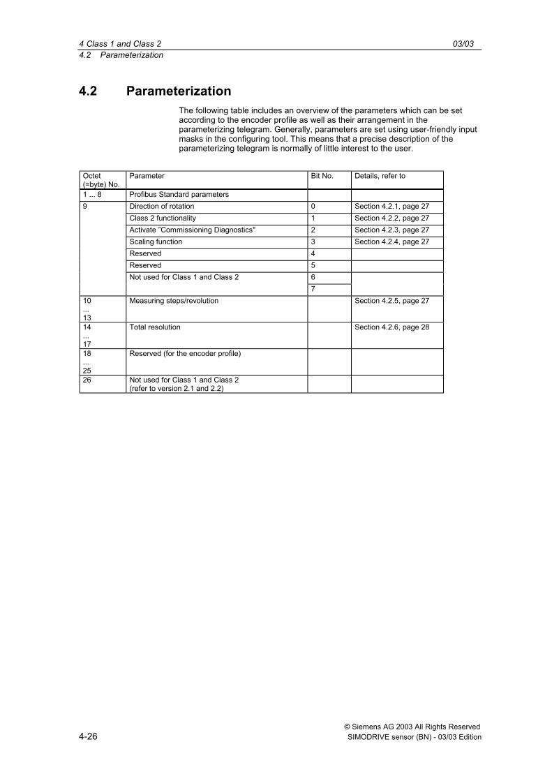
4.2 ParameterizationThe following table includes an overview of the parameters which can be setaccording to the encoder profile as well as their arrangement in theparameterizing telegram. Generally, parameters are set using user-friendly inputmasks in the configuring tool. This means that a precise description of theparameterizing telegram is normally of little interest to the user.
Octet(=byte) No.
Parameter Bit No. Details, refer to
1 ... 8 Profibus Standard parameters9 Direction of rotation 0 Section 4.2.1, page 27
Class 2 functionality 1 Section 4.2.2, page 27Activate Commissioning Diagnostics" 2 Section 4.2.3, page 27Scaling function 3 Section 4.2.4, page 27Reserved 4Reserved 5
6Not used for Class 1 and Class 27
10...13
Measuring steps/revolution Section 4.2.5, page 27
14...17
Total resolution Section 4.2.6, page 28
18...25
Reserved (for the encoder profile)
26 Not used for Class 1 and Class 2(refer to version 2.1 and 2.2)

03/03 4 Class 1 and Class 24.2 Parameterization
© Siemens AG 2003 All Rights ReservedSIMODRIVE sensor (BN) - 03/03 Edition 4-27
4.2.1 Direction of rotation
The direction of rotation defines the counting direction when the process actualvalue is output as the shaft rotates clockwise (CW) or counter-clockwise (CCW)when viewing the shaft. The count direction is defined by bit 0 in octet 9:
Octet 9 bit 0 Direction of rotationwhen viewing the shaft
Output code
0 Clockwise increasing
1 Counter-clockwise increasing
For Class 1, this is the only parameter, which can be set.
4.2.2 Activating/de-activating Class 2 functionality
Using this switch, Class 2 angular encoders can be restricted to the functionalityof Class 1, i.e. the parameterizing capability is disabled. Bit 1 in octet 9 is set inorder to use the functions of a Class 2 encoder.
Octet 9 bit 1 Class 2 functionality
0 Switched-out
1 Switched-in
4.2.3 Activating/de-activating commissioning diagnostics
This function has no significance for the SIMODRIVE sensor absolute valueencoder.
4.2.4 Activating/de-activating the scaling function
The scaling function enables the resolution per revolution and the selected totalresolution to be parameterized. This switch should always be switched-in, if thefunctions of Class 2 (or manufacturer-specific classes) are to be used.
Octet 9 bit 3 Scaling function
0 Switched-out
1 Switched-in
4.2.5 Measuring steps per revolutionThe Measuring steps per revolution parameter is used to program the absolutevalue encoder so that a required number of steps can be realized, referred toone revolution.
If a value greater than the basic resolution of the absolute value encoder isselected as resolution per revolution, the output code is no longer in singlesteps.
For absolute value encoders from version "A06", in this case, a parameter erroris displayed indicating that the device doesn't go into cyclic data transfer.
Octet 10 11 12 13

4 Class 1 and Class 2 03/034.2 Parameterization
© Siemens AG 2003 All Rights Reserved4-28 SIMODRIVE sensor (BN) - 03/03 Edition
Octet 10 11 12 13
Bit 31 - 24 23 - 16 15 - 8 7 - 0
Data 231 to 224 223 to 216 215 to 28 27 to 20
Required number of measuring steps per revolution
4.2.6 Total resolution
Octet 14 15 16 17
Bit 31 - 24 23 - 16 15 - 8 7 - 0
Data 231 to 224 223 to 216 215 to 28 27 to 20
Selected total resolution in measuring steps
The user can adapt the measuring range of the device using the Totalresolution parameter: The absolute value encoder counts up to theparameterized total resolution and then starts again at 0.
Example: 100 steps are selected for each revolution, total resolution 12 800, andthen the absolute value encoder starts again at zero after 128 revolutions andthen counts up to 11 799.
For many configuring tools it is necessary to split-up the value into a high wordand low word; also refer to Page 34.
When entering the parameter "Total resolution" the following must still beobserved:
If n steps per revolution are selected, then the selected total resolution may notresult in the fact that the periods are longer than the maximum available(physical) number of revolutions of the device (refer to the rating plate). Forinstance, for a multi-turn device with 4096 revolutions, the total resolution mustbe less than 4096 times the parameterized number of steps per revolution:
Total resolution < measuring steps per revolution x number of revolutions(physical revolutions)
If this is not observed, then the LEDs in the connecting cover display aparameterizing error and the device does not go into cyclic data transfer.
For older versions, when selecting the total resolution, an additional rule had tobe observed (refer below). If the total resolution was not selected in compliancewith this rule, when using the device on a so-called endless axis/ rotary axis,when the physical zero was exceeded, a step was output. For new devices(version A06), this particular problem has been resolved using an internalsoftware routine. This means that the rule, shown below, can be ignored for newdevices.

03/03 4 Class 1 and Class 24.2 Parameterization
© Siemens AG 2003 All Rights ReservedSIMODRIVE sensor (BN) - 03/03 Edition 4-29
Note
The internal software routine only intervenes if the device is operational. If theencoder shaft is rotated further than 1024 revolutions, and if the device is notconnected to the power supply voltage, problems can occur. If this situationcan occur in the application itself, the following rule should also be observedfor new devices:
The periods, i.e. total resolution/measuring steps per revolution must be aninteger number. This must fit an integer number of times (integer multiple) in4096. Thus, the following equation must apply:
(4096 x measuring steps per revolution) / total resolution = integer number

4 Class 1 and Class 2 03/034.3 Data transfer in normal operation
© Siemens AG 2003 All Rights Reserved4-30 SIMODRIVE sensor (BN) - 03/03 Edition
4.3 Data transfer in normal operationThe so-called DDLM_Data_Exchange mode is the normal status when operatingthe system. When requested to do so, the absolute value encoder sends actual(position) values to the master. On the other hand, the absolute value encoder canalso receive cyclic data (e.g. the preset value for Class 2 encoders).
4.3.1 Transferring the process actual valueFor multi-turn encoders, the actual position value is transferred to the master as32-bit value (double word):
Word Word 1Function Status bitsBit 31 30 29 28 27 26 25
0 0 0 0 0 0 0
Word Word 1Function Status bitsBit 24 23 22 21 20 19 18 17 16
X X X X X X X X X
Word Word 0Function Process actual valueBit 15 14 13 12 11 10 9 8 7 6 5 4 3 2 1 0
X X X X X X X X X X X X X X X X
Analog to this, for single-turn encoders data is transferred as 16-bit value (word).
4.3.2 Preset functionThe encoder zero point can be adapted to the mechanical zero of the systemusing the preset function The rotary encoder actual value is set to the required"preset value" by setting the preset value. The device computes the requiredzero offset and saves this in an EEPROM so that it is non-volatile (this takes lessthan 40 ms).The preset value is activated by setting bit 31 in the (peripheral) output doubleword (this is transferred with a rising signal edge). The preset value isautomatically set after the scaling parameters have been transferred, i.e. thepreset value refers to the scaled actual value.(This procedure is essentially the same for single-turn encoder versions in thiscase, bit 15 is used to activate the preset value.)
Status bitsBit 31 30 29 28 27 26 25
Master → AWC 1 0 0 0 0 0 0AWC → Master 0 0 0 0 0 0 0Master → AWC 0 0 0 0 0 0 0AWC → Master 0 0 0 0 0 0 0
Data bitsBit 24 23 22 21 20 19 18 17 16 15 14 13 12 11 10 9 8 7 6 5 4 3 2 1 0
Master → AWC Required value is transferred (= preset value)AWC → Master New = required process actual value is transferred hereMaster → AWC Reset bit 31 normal modeAWC → Master New = required process actual value is transferred here
If high precision is required, the preset mode should only be executed when theencoder shaft is at a standstill. If the shaft moves quickly during this time, offsetscan occur, as even when the preset value is set, bus propagation times occur(bus delay times).

© Siemens AG 2003 All Rights ReservedSIMODRIVE sensor (BN) - 03/03 Edition 5-31
Encoder Classes, Version 2.1 and 2.2
5.1 Parameters .....................................................................................................5-335.1.1 Activating the manufacturer-specific parameters ...........................................5-335.1.2 Required measuring steps .............................................................................5-335.1.3 Resolution reference ......................................................................................5-345.1.4 Activating the commissioning mode ...............................................................5-355.1.5 Reduced diagnostics ......................................................................................5-355.1.6 Software limit switches ...................................................................................5-365.1.7 Physical measuring steps...............................................................................5-375.1.8 Absolute value encoder type ..........................................................................5-385.1.9 Dimension units of the velocity.......................................................................5-38
5.2 Data transfer in the normal mode...................................................................5-39
5.3 The commissioning mode ..............................................................................5-405.3.1 Setting the direction of rotation.......................................................................5-415.3.2 Starting teach-in .............................................................................................5-415.3.3 Stopping teach-in ...........................................................................................5-425.3.4 Preset value....................................................................................................5-42
5

5 Encoder Classes, Version 2.1 and 2.2 03/035.1 Parameters
© Siemens AG 2003 All Rights Reserved5-32 SIMODRIVE sensor (BN) - 03/03 Edition
Using the manufacturer-specific encoder classes, Version 2.1 and Version 2.2, theabsolute value encoder offers, in addition to the functions in compliance with theencoder profile, features such as commissioning mode (teach-in mode), velocityoutput and limit switch.
The transfer of the individual parameters in the parameterizing telegram is listed inthe following Table. The following also applies in this case: Generally, users applythe user-friendly input masks (input screen forms) in the configuring tool; thestructure of the parameterizing telegram is only of marginal interest in exceptionalcases.
Details ref. toOctet (byte)No.
Parameter BitNo. Sect. Page
1 .. 8 Profibus Standard parametersDirection of rotation 0 4.2.1 27Class 2 functionality 1 4.2.2 27Commissioning diagnostics 2 4.2.3 27Scaling function 3 4.2.4 27Reserved 4Reserved 5Activate manufacturer-specific parameters (octet 26) 6 5.1.1 33
9
Reserved 710 .. 13 Required measuring steps (ref.: Octet 26 bits 0 and 1) 5.1.2 3314 .. 17 Total resolution 4.2.6 2818 .. 25 Reserved
0Reference for required measuring steps1
5.1.3 34
Activate commissioning mode 2 5.1.4 35Reduced diagnostics 3 5.1.5 35Reserved 4Activate lower software limit switch 5 5.1.6 36Activate upper software limit switch 6 5.1.6 36
26
Activate the parameter from octet 27 7 5.1.1 3327 .. 30 Lower limit switch 5.1.6 3631 .. 34 Upper limit switch 5.1.6 3635 .. 38 Physical measuring steps 5.1.7 37
Reserved 0Absolute value encoder type (single/multi-turn) 1 5.1.8 38Reserved 2Reserved 3
4Selecting the dimension units for velocity output5
5.1.9 38
Reserved 6
39
Reserved 7

03/03 5 Encoder Classes, Version 2.1 and 2.25.1 Parameters
© Siemens AG 2003 All Rights ReservedSIMODRIVE sensor (BN) - 03/03 Edition 5-33
5.1 ParametersThe manufacturer-specific parameters are described in more detail in the followingtext. The description of the (also supported) parameters according to the encoderprofile should be taken from Section 4.
5.1.1 Activating the manufacturer-specific parameters
The manufacturer-specific parameter byte 26 is activated using bit 6 in octet 9.
In turn, the manufacturer-specific bytes 27-39 are activated in byte 26.
When selecting the encoder classes, Version 2.1 or Version 2.2, this is realizedautomatically. These bits are only of significance if they are directly and manuallyparameterized in the hexadecimal notation.
Octet 9 bit 6 Octet 260 De-activated1 Activated
Octet 26 bit 7 Octet 27 390 De-activated1 Activated
5.1.2 Required measuring steps
The "required measuring steps" parameter is used to program the device so thatany number of measuring steps, referred to a revolution, the complete measuringrange or any partial measuring range can be covered.
Octet 10 11 12 13Bit 31 - 24 23 - 16 15 - 8 7 0Data 231 to 224 223 to 216 215 to 28 27 to 20
Required measuring steps
The parameter "Resolution reference" (refer to 5.1.3) is used to define thereference for the measuring steps entered here. If "per revolution" is selected hereas reference for the requested measuring steps, then the measuring range can beadapted using the "Total resolution" parameter. In this case, the rules, listed inSection 4.2.6, should be carefully observed.
Note
For many configuring tools it is necessary to split-up the word into a highword and low word; also refer to Page 54.

5 Encoder Classes, Version 2.1 and 2.2 03/035.1 Parameters
© Siemens AG 2003 All Rights Reserved5-34 SIMODRIVE sensor (BN) - 03/03 Edition
5.1.3 Resolution reference
This parameter is used to specify the reference for the "Required measuringsteps" (refer to 5.1.2) which is entered:
− revolution
− maximum total resolution
− physical measuring steps
Requested resolution per revolution
In this case, the position value is scaled so that the position value increases by thenumber of required measuring steps at each revolution. In addition, in thisparticular case, the "Total resolution" parameter is evaluated. This can be used toadapt the measuring range (refer to 4.2.6).
Requested resolution per maximum total resolution
The requested measuring steps which are entered refer to the completemeasuring range of the device, i.e. the device outputs the parameterized numberof measuring steps over the complete (physical) number of revolutions.
Requested resolution per physical measuring steps
In this case, the required number of steps refers to the physical measuring steps,entered using parameter "Physical measuring steps" (also refer to Section 5.1.7).In this particular case physical steps mean the following: The numerical valuewhich is read from the coding disk internally from the absolute value encoder (e.g.4096 steps per revolution for the standard 12-bit version). Gearbox factors can befreely set using this option.
Reference Octet 26 bit 0 Octet 26 bit 1Per revolution 0 0Per maximum total resolution 1 0Per physical measuring steps(= steps specified in octet 35-38)
0 1

03/03 5 Encoder Classes, Version 2.1 and 2.25.1 Parameters
© Siemens AG 2003 All Rights ReservedSIMODRIVE sensor (BN) - 03/03 Edition 5-35
5.1.4 Activating the commissioning mode
Bit 2 in octet 26 represents a switch for the so-called commissioning mode. Thecommissioning mode is a specific status of the device which can be used totransfer additional parameters, extending beyond the preset value, to the absolutevalue encoder. When the commissioning mode has been activated, a so-called"teach-in" can be executed. This means that the gearbox factor can be determinedby directly moving the system. In this particular mode (this can be identified at theunit as a result of the flashing green LED), the direction of rotation and scaling, setwhen configuring the system, are ignored and instead, the values saved in theEEPROM are used.
The device can also be continually operated in the commissioning mode; however,we recommend that the parameters, determined in the commissioning mode, aretransferred to the configuring and the device is then subsequently used in thenormal mode (this means that it is possible to replace the device without having tocarry-out a new teach-in).
A detailed description of the commissioning mode is provided in Section 5.3.
Octet 26 bit 2 Commissioning mode
0 Disabled
1 Enabled
5.1.5 Reduced diagnostics
For some Profibus masters, the full number of diagnostic bytes can result inproblems (standard diagnostics: 57 bytes). Especially older masters often cannotprocess the full number of diagnostic bytes. With SIEMENS absolute valueencoders it is possible to reduce the number of diagnostic bytes output from theabsolute value encoder to 16. Only 16 diagnostic bytes are output if the "Class 1"device class is selected.
Octet 26 bit 3 Diagnostics
0 Standard = 57 bytes
1 Reduced = 16 bytes
5 Encoder Classes, Version 2.1 and 2.2 03/035.1 Parameters
© Siemens AG 2003 All Rights Reserved5-36 SIMODRIVE sensor (BN) - 03/03 Edition
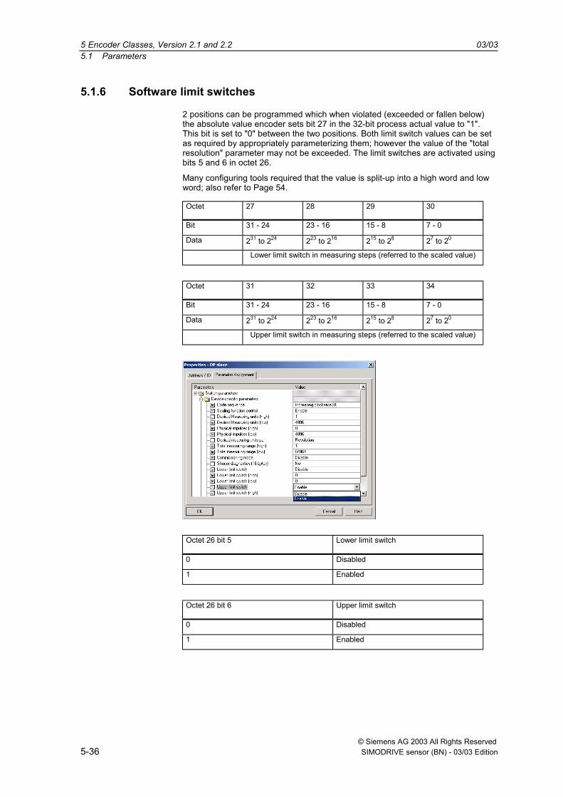
5.1.6 Software limit switches
2 positions can be programmed which when violated (exceeded or fallen below)the absolute value encoder sets bit 27 in the 32-bit process actual value to "1".This bit is set to "0" between the two positions. Both limit switch values can be setas required by appropriately parameterizing them; however the value of the "totalresolution" parameter may not be exceeded. The limit switches are activated usingbits 5 and 6 in octet 26.
Many configuring tools required that the value is split-up into a high word and lowword; also refer to Page 54.
Octet 27 28 29 30
Bit 31 - 24 23 - 16 15 - 8 7 - 0
Data 231 to 224 223 to 216 215 to 28 27 to 20
Lower limit switch in measuring steps (referred to the scaled value)
Octet 31 32 33 34
Bit 31 - 24 23 - 16 15 - 8 7 - 0
Data 231 to 224 223 to 216 215 to 28 27 to 20
Upper limit switch in measuring steps (referred to the scaled value)
Octet 26 bit 5 Lower limit switch
0 Disabled
1 Enabled
Octet 26 bit 6 Upper limit switch
0 Disabled
1 Enabled
03/03 5 Encoder Classes, Version 2.1 and 2.25.1 Parameters
© Siemens AG 2003 All Rights ReservedSIMODRIVE sensor (BN) - 03/03 Edition 5-37
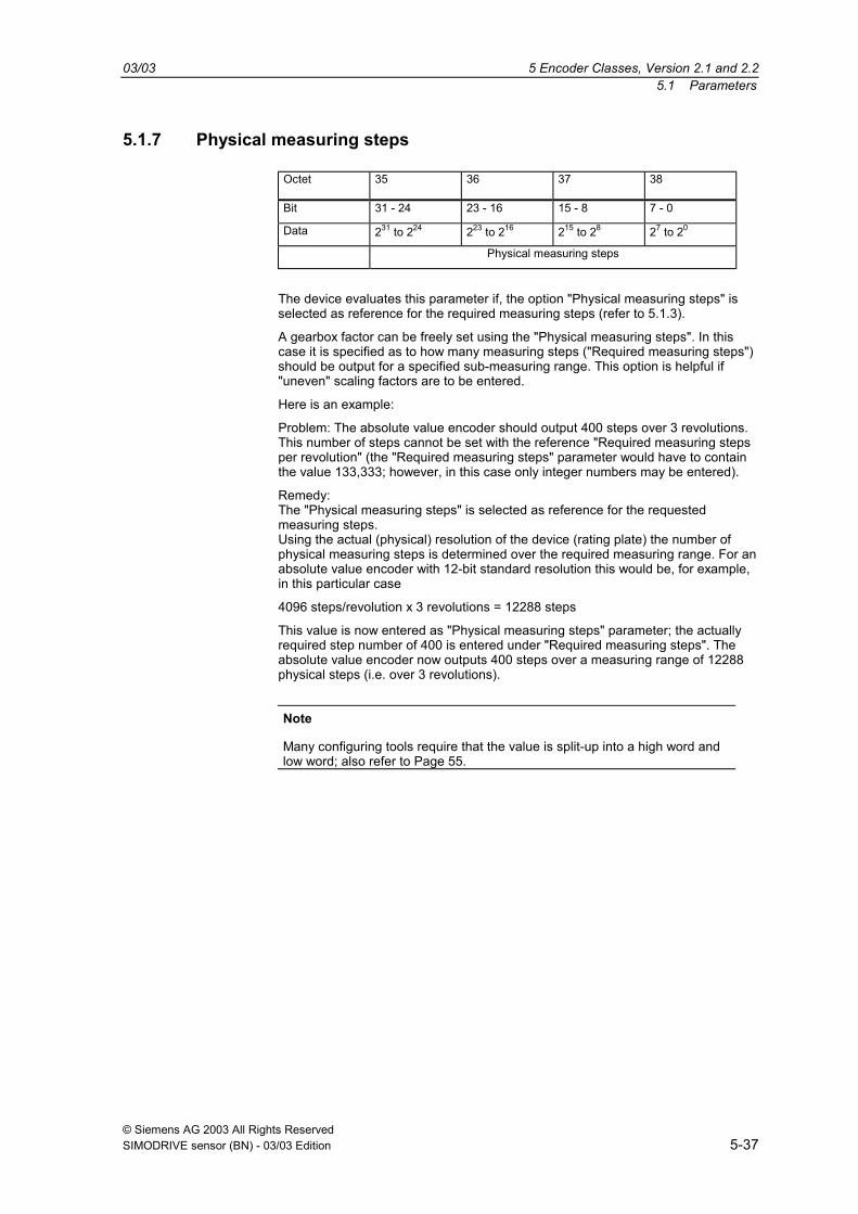
5.1.7 Physical measuring steps
Octet 35 36 37 38
Bit 31 - 24 23 - 16 15 - 8 7 - 0
Data 231 to 224 223 to 216 215 to 28 27 to 20
Physical measuring steps
The device evaluates this parameter if, the option "Physical measuring steps" isselected as reference for the required measuring steps (refer to 5.1.3).
A gearbox factor can be freely set using the "Physical measuring steps". In thiscase it is specified as to how many measuring steps ("Required measuring steps")should be output for a specified sub-measuring range. This option is helpful if"uneven" scaling factors are to be entered.
Here is an example:
Problem: The absolute value encoder should output 400 steps over 3 revolutions.This number of steps cannot be set with the reference "Required measuring stepsper revolution" (the "Required measuring steps" parameter would have to containthe value 133,333; however, in this case only integer numbers may be entered).
Remedy:The "Physical measuring steps" is selected as reference for the requestedmeasuring steps.Using the actual (physical) resolution of the device (rating plate) the number ofphysical measuring steps is determined over the required measuring range. For anabsolute value encoder with 12-bit standard resolution this would be, for example,in this particular case
4096 steps/revolution x 3 revolutions = 12288 steps
This value is now entered as "Physical measuring steps" parameter; the actuallyrequired step number of 400 is entered under "Required measuring steps". Theabsolute value encoder now outputs 400 steps over a measuring range of 12288physical steps (i.e. over 3 revolutions).
Note
Many configuring tools require that the value is split-up into a high word andlow word; also refer to Page 55.

5 Encoder Classes, Version 2.1 and 2.2 03/035.1 Parameters
© Siemens AG 2003 All Rights Reserved5-38 SIMODRIVE sensor (BN) - 03/03 Edition
5.1.8 Absolute value encoder type
The type of the absolute value encoder (single or multi-turn) is defined in bit 1 ofoctet 39. When the encoder class is selected this is realized automatically. Theuser must only observe these parameters if the parameterization is done directly inthe hexadecimal code.
Octet 39 bit 1 Type
0 Single-turn
1 Multi-turn
5.1.9 Dimension units of the velocity
The units in which the velocity is output (Version 2.2) is set using this parameter.This basis is saved in bit 4 and 5 of the octet 39.
Units Bit 4 Bit 5
Steps/second 0 0
Steps/100 ms 1 0
Steps/10 ms 0 1
Revolutions/minute 1 1
03/03 5 Encoder Classes, Version 2.1 and 2.25.2 Data transfer in the normal mode
© Siemens AG 2003 All Rights ReservedSIMODRIVE sensor (BN) - 03/03 Edition 5-39
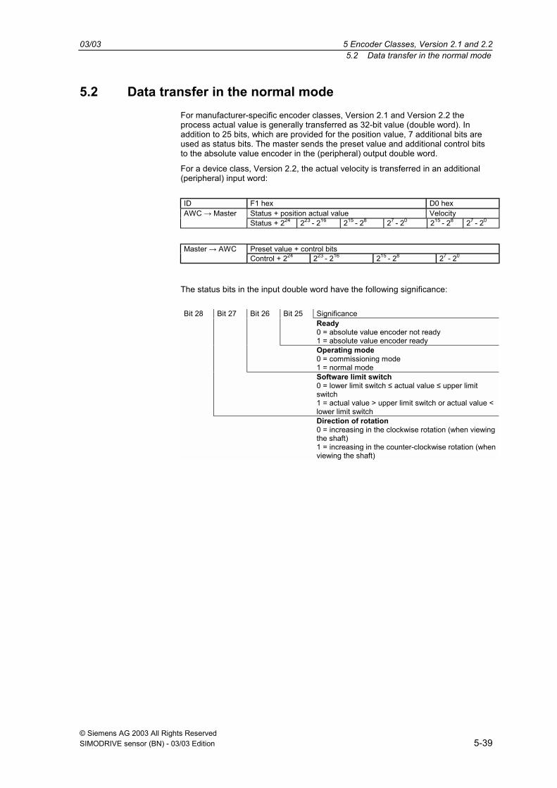
5.2 Data transfer in the normal modeFor manufacturer-specific encoder classes, Version 2.1 and Version 2.2 theprocess actual value is generally transferred as 32-bit value (double word). Inaddition to 25 bits, which are provided for the position value, 7 additional bits areused as status bits. The master sends the preset value and additional control bitsto the absolute value encoder in the (peripheral) output double word.
For a device class, Version 2.2, the actual velocity is transferred in an additional(peripheral) input word:
ID F1 hex D0 hexStatus + position actual value VelocityAWC → MasterStatus + 224 223 - 216 215 - 28 27 - 20 215 - 28 27 - 20
Preset value + control bitsMaster → AWCControl + 224 223 - 216 215 - 28 27 - 20
The status bits in the input double word have the following significance:
Bit 28 Bit 27 Bit 26 Bit 25 SignificanceReady0 = absolute value encoder not ready1 = absolute value encoder readyOperating mode0 = commissioning mode1 = normal modeSoftware limit switch0 = lower limit switch ≤ actual value ≤ upper limitswitch1 = actual value > upper limit switch or actual value <lower limit switchDirection of rotation0 = increasing in the clockwise rotation (when viewingthe shaft)1 = increasing in the counter-clockwise rotation (whenviewing the shaft)
5 Encoder Classes, Version 2.1 and 2.2 03/035.3 The commissioning mode
© Siemens AG 2003 All Rights Reserved5-40 SIMODRIVE sensor (BN) - 03/03 Edition
5.3 The commissioning modeIf the absolute value encoder is switched into the commissioning mode using theappropriate parameterization, then gearbox factors can be directly determined inthe system using a so-called "teach-in".
The absolute value encoder signals when it is in the commissioning mode by theflashing green LED in the connecting cover and using bit 26 in the input doubleword (this is set to 0).
In the commissioning mode, the parameters, set in the configuring (direction ofrotation, scaling) are ignored and instead the values, saved in the internalEEPROM, are used. If the direction of rotation and gearbox factor are changed inthe commissioning mode, then the new values are saved in the EEPROM and thedevice operates with these values.
The principle mode of operation in the commissioning mode is as follows:
− The device is installed in the system.
− The commissioning mode is switched-in using the appropriateparameterization (refer to 5.14).
− If required, the direction of rotation is modified.
− The system is moved into the initial position.
− The start command for the teach-in is transferred to the absolute valueencoder.
− The system is moved to the end position.
− The required step number is transferred to the absolute value encoder withthe teach-in stop command.
− The preset value is set.
− The values, determined in the teach-in phase are transferred into theconfiguring (parameter).
− The commissioning mode is switched-out in the parameterization.
03/03 5 Encoder Classes, Version 2.1 and 2.25.3 The commissioning mode
© Siemens AG 2003 All Rights ReservedSIMODRIVE sensor (BN) - 03/03 Edition 5-41
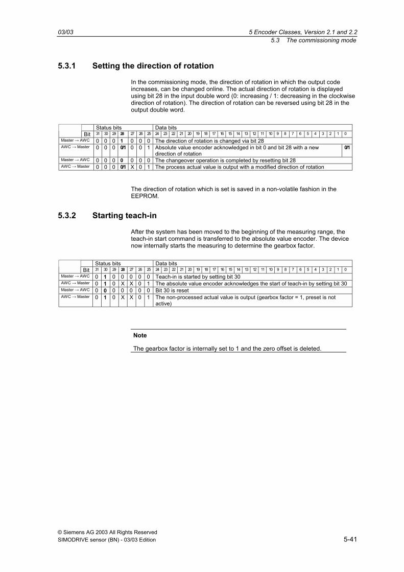
5.3.1 Setting the direction of rotation
In the commissioning mode, the direction of rotation in which the output codeincreases, can be changed online. The actual direction of rotation is displayedusing bit 28 in the input double word (0: increasing / 1: decreasing in the clockwisedirection of rotation). The direction of rotation can be reversed using bit 28 in theoutput double word.
Status bits Data bitsBit 31 30 29 28 27 26 25 24 23 22 21 20 19 18 17 16 15 14 13 12 11 10 9 8 7 6 5 4 3 2 1 0
Master → AWC 0 0 0 1 0 0 0 The direction of rotation is changed via bit 28AWC → Master 0 0 0 0/1 0 0 1 Absolute value encoder acknowledged in bit 0 and bit 28 with a new
direction of rotation0/1
Master → AWC 0 0 0 0 0 0 0 The changeover operation is completed by resetting bit 28AWC → Master 0 0 0 0/1 X 0 1 The process actual value is output with a modified direction of rotation
The direction of rotation which is set is saved in a non-volatile fashion in theEEPROM.
5.3.2 Starting teach-in
After the system has been moved to the beginning of the measuring range, theteach-in start command is transferred to the absolute value encoder. The devicenow internally starts the measuring to determine the gearbox factor.
Status bits Data bitsBit 31 30 29 28 27 26 25 24 23 22 21 20 19 18 17 16 15 14 13 12 11 10 9 8 7 6 5 4 3 2 1 0
Master → AWC 0 1 0 0 0 0 0 Teach-in is started by setting bit 30AWC → Master 0 1 0 X X 0 1 The absolute value encoder acknowledges the start of teach-in by setting bit 30Master → AWC 0 0 0 0 0 0 0 Bit 30 is resetAWC → Master 0 1 0 X X 0 1 The non-processed actual value is output (gearbox factor = 1, preset is not
active)
Note
The gearbox factor is internally set to 1 and the zero offset is deleted.
5 Encoder Classes, Version 2.1 and 2.2 03/035.3 The commissioning mode
© Siemens AG 2003 All Rights Reserved5-42 SIMODRIVE sensor (BN) - 03/03 Edition
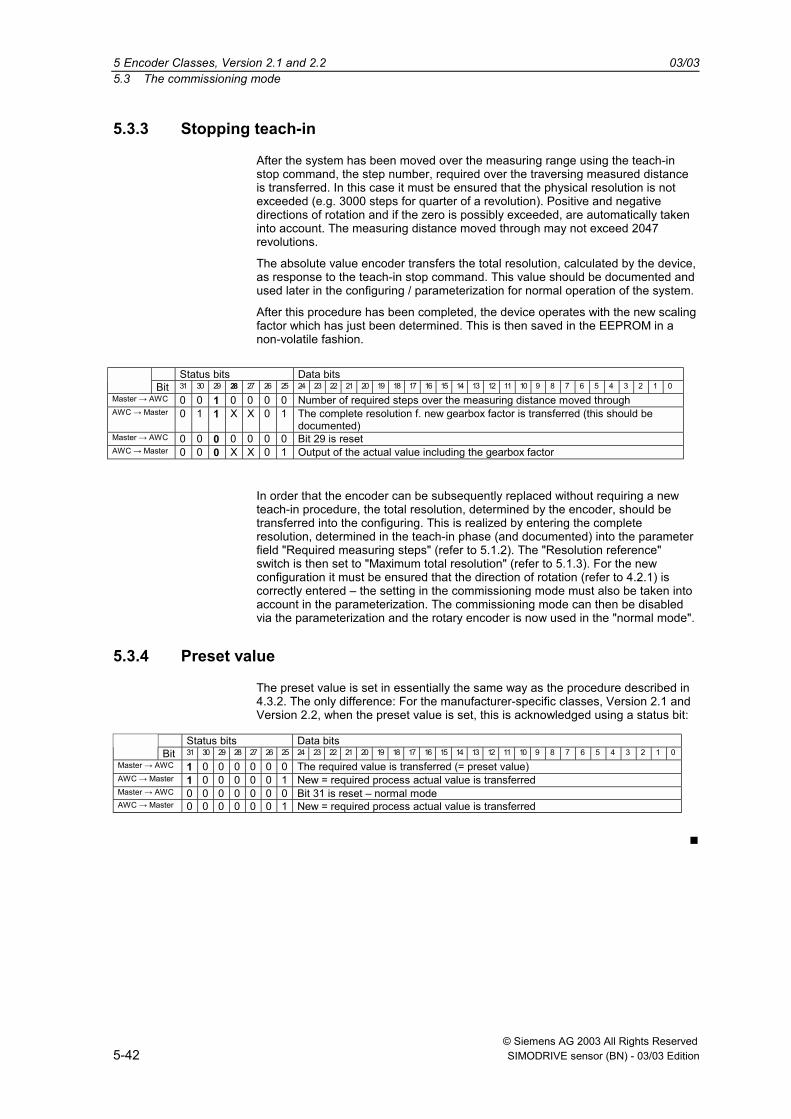
5.3.3 Stopping teach-in
After the system has been moved over the measuring range using the teach-instop command, the step number, required over the traversing measured distanceis transferred. In this case it must be ensured that the physical resolution is notexceeded (e.g. 3000 steps for quarter of a revolution). Positive and negativedirections of rotation and if the zero is possibly exceeded, are automatically takeninto account. The measuring distance moved through may not exceed 2047revolutions.
The absolute value encoder transfers the total resolution, calculated by the device,as response to the teach-in stop command. This value should be documented andused later in the configuring / parameterization for normal operation of the system.
After this procedure has been completed, the device operates with the new scalingfactor which has just been determined. This is then saved in the EEPROM in anon-volatile fashion.
Status bits Data bitsBit 31 30 29 28 27 26 25 24 23 22 21 20 19 18 17 16 15 14 13 12 11 10 9 8 7 6 5 4 3 2 1 0
Master → AWC 0 0 1 0 0 0 0 Number of required steps over the measuring distance moved throughAWC → Master 0 1 1 X X 0 1 The complete resolution f. new gearbox factor is transferred (this should be
documented)Master → AWC 0 0 0 0 0 0 0 Bit 29 is resetAWC → Master 0 0 0 X X 0 1 Output of the actual value including the gearbox factor
In order that the encoder can be subsequently replaced without requiring a newteach-in procedure, the total resolution, determined by the encoder, should betransferred into the configuring. This is realized by entering the completeresolution, determined in the teach-in phase (and documented) into the parameterfield "Required measuring steps" (refer to 5.1.2). The "Resolution reference"switch is then set to "Maximum total resolution" (refer to 5.1.3). For the newconfiguration it must be ensured that the direction of rotation (refer to 4.2.1) iscorrectly entered the setting in the commissioning mode must also be taken intoaccount in the parameterization. The commissioning mode can then be disabledvia the parameterization and the rotary encoder is now used in the "normal mode".
5.3.4 Preset value
The preset value is set in essentially the same way as the procedure described in4.3.2. The only difference: For the manufacturer-specific classes, Version 2.1 andVersion 2.2, when the preset value is set, this is acknowledged using a status bit:
Status bits Data bitsBit 31 30 29 28 27 26 25 24 23 22 21 20 19 18 17 16 15 14 13 12 11 10 9 8 7 6 5 4 3 2 1 0
Master → AWC 1 0 0 0 0 0 0 The required value is transferred (= preset value)AWC → Master 1 0 0 0 0 0 1 New = required process actual value is transferredMaster → AWC 0 0 0 0 0 0 0 Bit 31 is reset normal modeAWC → Master 0 0 0 0 0 0 1 New = required process actual value is transferred
© Siemens AG 2003 All Rights ReservedSIMODRIVE sensor (BN) - 03/03 Edition 6-43
Diagnostic Messages
6.1 Overview.........................................................................................................6-44
6.2 Diagnostic messages which are supported....................................................6-456.2.1 Expanded diagnostics header ........................................................................6-456.2.2 Memory errors ................................................................................................6-456.2.3 Operating state...............................................................................................6-456.2.4 Encoder type ..................................................................................................6-456.2.5 Single-turn resolution .....................................................................................6-456.2.6 Number of revolutions ....................................................................................6-456.2.7 Operating time alarm......................................................................................6-466.2.8 Profile version.................................................................................................6-466.2.9 Software version.............................................................................................6-466.2.10 Operating time................................................................................................6-466.2.11 Zero offset ......................................................................................................6-466.2.12 Parameterized resolution per revolution.........................................................6-466.2.13 Parameterized total resolution........................................................................6-476.2.14 Serial number .................................................................................................6-47
6.3 Status signals using LEDs in the connecting cover........................................6-48
6

6 Diagnostic Messages 03/036.1 Overview
© Siemens AG 2003 All Rights Reserved6-44 SIMODRIVE sensor (BN) - 03/03 Edition
6.1 OverviewWhen requested by the master, in the DDLM_Slave_Diag mode, a series ofdata is transferred. There are 57 pieces of diagnostics data. Exception:Reduced diagnostics (refer to 5.1.5). The diagnostics data are outputaccording to the Profibus Standard (octet 1-6) and the encoder profile rules(from octet 7).
Diagnostics function Data type Diagnosticsoctet no.
Encoder class
Station status 1 (ref. to: ProfibusStandard)
Octet 1 1
Station status 2 (ref. to: ProfibusStandard)
Octet 2 1
Station status 3 (ref. to: ProfibusStandard)
Octet 3 1
Diagnostics Master Add Octet 4 1
PNO identification number Octet 5,6 1
Extended diagnostics header Octet String 7 1
Alarm messages Octet String 8 1
Operating status Octet String 9 1
Encoder type Octet String 10 1
Resolution per revolution (hardware) unsigned 32 11 - 14 1
Number of revolutions (hardware) unsigned 32 15, 16 1
Additional alarm messages Octet String 17 2
Supported alarm messages Octet String 18, 19 2
Alarm messages Octet String 20, 21 2
Supported alarms Octet String 22, 23 2
Profile version Octet String 24, 25 2
Software version Octet String 26, 27 2
Operating time Unsigned 32 28 - 31 2
Zero offset Unsigned 32 32 - 35 2
Manufacturer-specific: Offset value Unsigned 32 36 - 39 2
Parameterized resolution per revolution Unsigned 32 40 - 43 2
Parameterized total resolution Unsigned 32 44 - 47 2
Serial number ASCII String 48 - 57 2

03/03 6 Diagnostic Messages6.2 Diagnostic messages which are supported
© Siemens AG 2003 All Rights ReservedSIMODRIVE sensor (BN) - 03/03 Edition 6-45
6.2 Diagnostic messages which are supportedThe implemented diagnostics messages are described in more detail below.
6.2.1 Expanded diagnostics header
The length of the extended diagnostic bytes, including diagnostics header, iscontained in diagnostics byte 7.
6.2.2 Memory errors
Bit 4 in diagnostics byte 8 is used to display whether a memory error hasoccurred. Memory errors means in this case, that the angular encoderEEPROM no longer functions correctly and the preset value is no longer savedso that it is kept during power outages (non-volatile data save).
Bit Definition 0 1
4 Memory error (defect in theEEPROM)
No Yes
6.2.3 Operating state
The operating parameters which are set can be interrogated using diagnosticsbyte 9.
Bit Definition 0 1
0 Direction of rotation CW CCW
1 Class 2 functionality Off On
2 Diagnostic routine Off On
3 Scaling function Off On
6.2.4 Encoder type
The angular encoder version can be interrogated using diagnostics byte 10.
Byte 10 Definition
0 Single-turn angular encoder
1 Multi-turn angular encoder
6.2.5 Single-turn resolution
The hardware resolution per revolution of the angular encoder can beinterrogated via diagnostic bytes 11-14.
6.2.6 Number of revolutions
The number of revolutions of the angular encoder which can be differentiatedbetween on the hardware side, can be interrogated using diagnostic bytes 15

6 Diagnostic Messages 03/036.2 Diagnostic messages which are supported
© Siemens AG 2003 All Rights Reserved6-46 SIMODRIVE sensor (BN) - 03/03 Edition
and 16. The two standard values are 1 for single-turn and/or 4096 for multi-turn.
6.2.7 Operating time alarm
The alarm signal when the operating time is exceeded, is output in bit 4 ofdiagnostic byte 20. This bit is set after 105 hours.
6.2.8 Profile version
The profile version of the angular encoder is saved in diagnostic bytes 24 and25:
Byte 24 25
Bit 15 - 8 7 - 0
Data 27 to 20 27 to 20
Service No. Index
6.2.9 Software version
The software version of the angular encoder is saved in diagnostic bytes 26and 27.
Octet 26 27
Bit 15 - 8 7 - 0
Data 27 to 20 27 to 20
Service No. Index
6.2.10 Operating time
The angular encoder operating time is kept in diagnostic bytes 28 to 31. Whenthe power supply voltage is connected, the operating time is saved every sixminutes in 0.1h steps in the angular encoder.
6.2.11 Zero offset
The zero offset is output in diagnostic bytes 32 to 35.
6.2.12 Parameterized resolution per revolution
The parameterized resolution per revolution is saved in diagnostic bytes 40 to43. This value is only valid, if the gearbox factor was calculated in theparameter mask using the setting Resolution per revolution (refer to 5.1.3).

03/03 6 Diagnostic Messages6.2 Diagnostic messages which are supported
© Siemens AG 2003 All Rights ReservedSIMODRIVE sensor (BN) - 03/03 Edition 6-47
6.2.13 Parameterized total resolution
The parameterized and calculated total resolution can be read-out ofdiagnostic bytes 44-47.
6.2.14 Serial number
Diagnostic bytes 48 - 57 are provided for a serial number. This signal haspresently not been implemented. The bytes are pre-assigned hex 2A (defaultvalue).
6 Diagnostic Messages 03/036.3 Status signals using LEDs in the connecting cover
© Siemens AG 2003 All Rights Reserved6-48 SIMODRIVE sensor (BN) - 03/03 Edition
6.3 Status signals using LEDs in the connecting cover
LED rot/red
LED grün/green
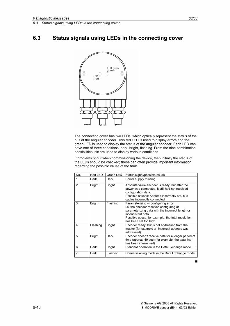
The connecting cover has two LEDs, which optically represent the status of thebus at the angular encoder. This red LED is used to display errors and thegreen LED is used to display the status of the angular encoder. Each LED canhave one of three conditions: dark, bright, flashing. From the nine combinationpossibilities, six are used to display various conditions.
If problems occur when commissioning the device, then initially the status ofthe LEDs should be checked; these can often provide important informationregarding the possible cause of the fault.
No. Red LED Green LED Status signal/possible cause1 Dark Dark Power supply missing
2 Bright Bright Absolute value encoder is ready, but after thepower was connected, it still had not receivedconfiguration data.Possible causes: Address incorrectly set, buscables incorrectly connected
3 Bright Flashing Parameterizing or configuring errori.e. the encoder receives configuring orparameterizing data with the incorrect length orinconsistent data.Possible cause: for example, the total resolutionhas been set too high
4 Flashing Bright Encoder ready, but is not addressed from themaster (for example an incorrect address wasaddressed)
5 Bright Dark Encoder doesnt receive data for a longer period oftime (approx. 40 sec) (for example, the data linehas been interrupted)
6 Dark Bright Standard operation in the Data Exchange mode
7 Dark Flashing Commissioning mode in the Data Exchange mode

© Siemens AG 2003 All Rights ReservedSIMODRIVE sensor (BN) - 03/03 Edition 7-49
Configuration Example STEP 7
7.1 Reading-in the GSD files ................................................................................7-50
7.2 Configuring the absolute value encoder.........................................................7-51
7.3 Selecting the device class ..............................................................................7-52
7.4 Parameterization ............................................................................................7-53
7

7 Configuration Example STEP 7 03/037.1 Reading-in the GSD files
© Siemens AG 2003 All Rights Reserved7-50 SIMODRIVE sensor (BN) - 03/03 Edition
7.1 Reading-in the GSD filesWhen used for the first time, the GSD file ("SIEM0024.gsd") must be installedin order to include the absolute value encoder in the hardware Catalog. To dothis, the "Install new GSD .." item should be selected in the "HW Config"window of the SIMATIC Manager under the menu item "Options". Theappropriate GSD file ("SIEM0024.gsd" or the German Version"SIEM0024.gsg") should be selected.The GSD file can be obtained from SIEMENS.
After the GSD file has been read-in, the absolute value encoder appears in thehardware Catalog under "PROFIBUS-DP" - "Other field devices" - "Encoder" -"SIMODRIVE sensor".
For more recent versions of the "SIMATIC Manager" the sensor is alreadyincluded in the hardware Catalog.

03/03 7 Configuration Example STEP 77.2 Configuring the absolute value encoder
© Siemens AG 2003 All Rights ReservedSIMODRIVE sensor (BN) - 03/03 Edition 7-51
7.2 Configuring the absolute value encoder
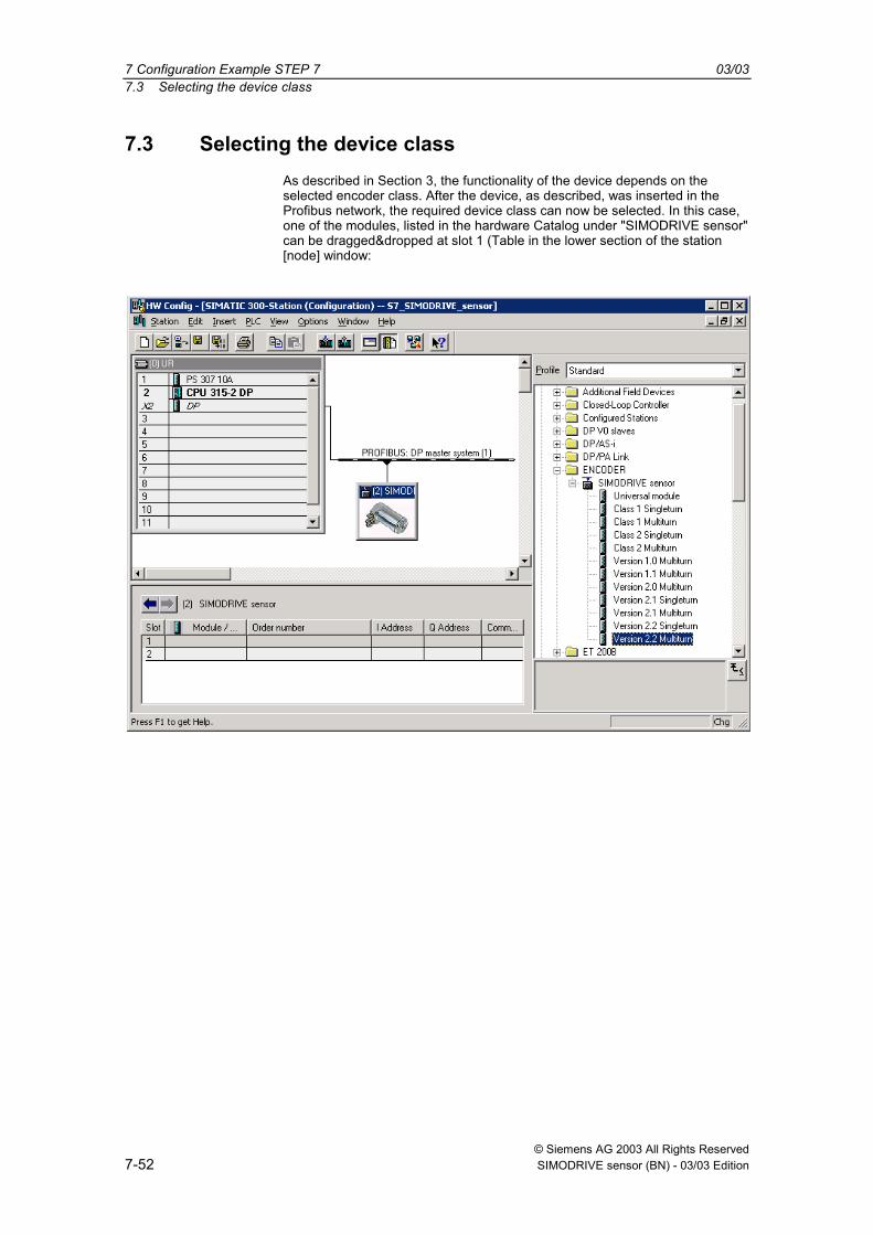
After the Profibus network has been configured in the hardware configuratorunder the menu item "Insert" "Master system" the absolute value encodercan be selected from the hardware Catalog and inserted in the network. To dothis, the "SIMODRIVE sensor" device is coupled to the bus by dragging &dropping it (or by double clicking on the module with the bus selected).
After the device has been inserted, the node address of the slave device isentered. This must match the address set in the connecting cover.
7 Configuration Example STEP 7 03/037.3 Selecting the device class
© Siemens AG 2003 All Rights Reserved7-52 SIMODRIVE sensor (BN) - 03/03 Edition
7.3 Selecting the device classAs described in Section 3, the functionality of the device depends on theselected encoder class. After the device, as described, was inserted in theProfibus network, the required device class can now be selected. In this case,one of the modules, listed in the hardware Catalog under "SIMODRIVE sensor"can be dragged&dropped at slot 1 (Table in the lower section of the station[node] window:

03/03 7 Configuration Example STEP 77.4 Parameterization
© Siemens AG 2003 All Rights ReservedSIMODRIVE sensor (BN) - 03/03 Edition 7-53
7.4 ParameterizationSelect the absolute value encoder to be parameterized in the configuring andthen double click on slot 1 (Table in the lower area of the station [node]window). The dialog box "Properties DP slave" is displayed. The defaultaddresses (if required) of the device can be changed here.
The "Parameterizing" tab should be selected to enter parameters.
The parameters of the device are now entered here. After the "Device-specificparameter" folder has been selected, then, depending on the encoder classwhich has been selected, different parameters can be entered. If there areseveral possibilities in the fields located to the right, then an additionalselection window opens with a double click. On the other hand, numericalvalues are directly entered. The example indicates the parameter selection forVersion 2.2 the device class with the highest functionality.
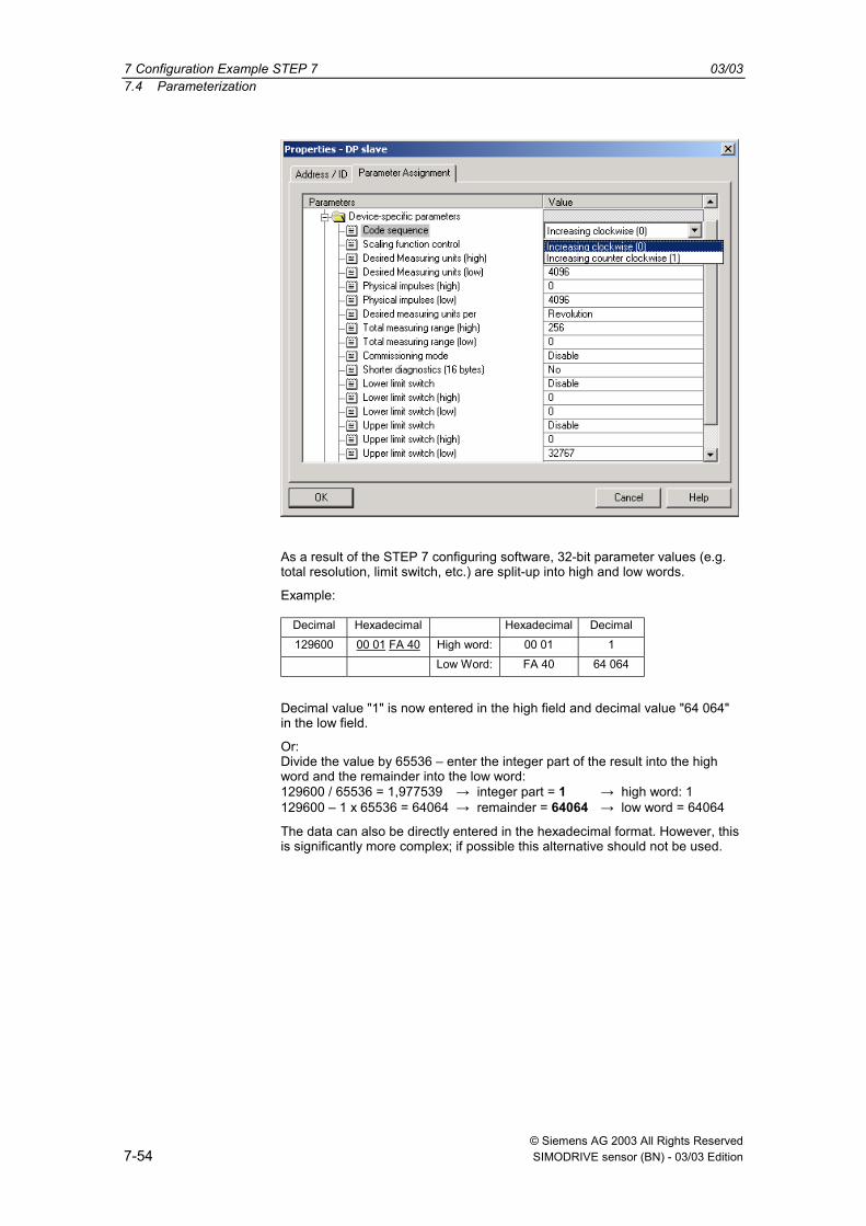
7 Configuration Example STEP 7 03/037.4 Parameterization
© Siemens AG 2003 All Rights Reserved7-54 SIMODRIVE sensor (BN) - 03/03 Edition
As a result of the STEP 7 configuring software, 32-bit parameter values (e.g.total resolution, limit switch, etc.) are split-up into high and low words.
Example:
Decimal Hexadecimal Hexadecimal Decimal129600 00 01 FA 40 High word: 00 01 1
Low Word: FA 40 64 064
Decimal value "1" is now entered in the high field and decimal value "64 064"in the low field.
Or:Divide the value by 65536 enter the integer part of the result into the highword and the remainder into the low word:129600 / 65536 = 1,977539 → integer part = 1 → high word: 1129600 1 x 65536 = 64064 → remainder = 64064 → low word = 64064
The data can also be directly entered in the hexadecimal format. However, thisis significantly more complex; if possible this alternative should not be used.
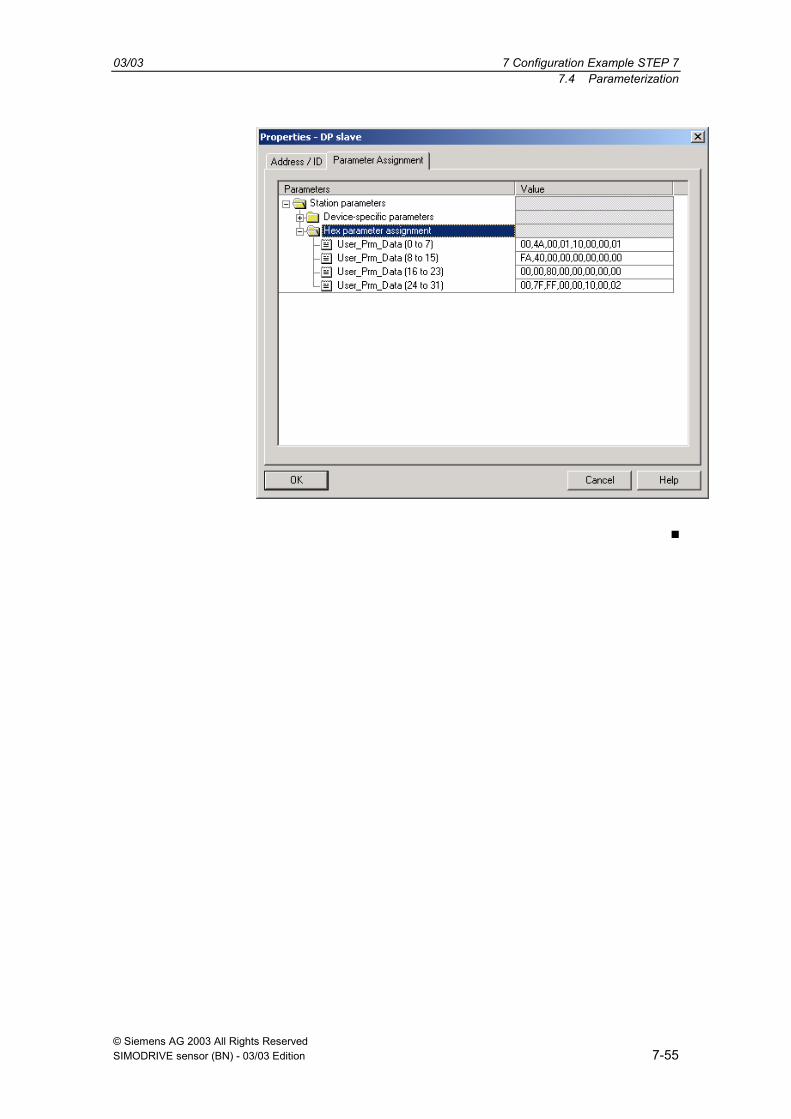
03/03 7 Configuration Example STEP 77.4 Parameterization
© Siemens AG 2003 All Rights ReservedSIMODRIVE sensor (BN) - 03/03 Edition 7-55

7 Configuration Example STEP 7 03/037.4 Parameterization
© Siemens AG 2003 All Rights Reserved7-56 SIMODRIVE sensor (BN) - 03/03 Edition
Space for your notes

© Siemens AG 2003 All Rights ReservedSIMODRIVE sensor (BN) - 03/03 Edition 8-57
DPV2 Functionality – General Information
8.1 Isochronous operation....................................................................................8-59
8.2 Slave-to-slave communication........................................................................8-60
8

8 DPV2 Functionality General Information 03/038.1 Isochronous operation
© Siemens AG 2003 All Rights Reserved8-58 SIMODRIVE sensor (BN) - 03/03 Edition
The latest generation of SIEMENS Profibus absolute value encoders supportsthe new Profibus functionality isochronous operation and slave-to-slavecommunications.

03/03 8 DPV2 Functionality General Information8.1 Isochronous operation
© Siemens AG 2003 All Rights ReservedSIMODRIVE sensor (BN) - 03/03 Edition 8-59
8.1 Isochronous operationIsochronous communication (equidistance) forms the basis for synchronizingseveral drives. In this case, Profibus slaves are synchronized to a cyclic clockcycle signal (GC) sent by the master as "Global-Control-Command". Theinstants in time where the actual value is sensed (TI) and the setpoint transfer(TO) within the bus cycle (TDP) can be selected in the configured software. Thismeans that the position values of several axes can be simultaneously sensedto a precision of just microseconds.
TDP TDP
GC GC GC
TI TO
S1 S2 S4S3 MSG Res./ GC S1 S2 S4S3 MSG Res./ GC
TDX TDX
TOmin

8 DPV2 Functionality General Information 03/038.2 Slave-to-slave communication
© Siemens AG 2003 All Rights Reserved8-60 SIMODRIVE sensor (BN) - 03/03 Edition
8.2 Slave-to-slave communicationThe slave-to-slave communication function allows Profibus slave devices to"listen to" the actual values of other slaves and use these as setpoints. A slavedevice, which provides its actual values to other slaves is called a "Publisher".Devices which listen to the actual values of other slaves are called"Subscribers". A master must initiate slave-to-slave communications and thiscan be realized within one DP cycle.

© Siemens AG 2003 All Rights ReservedSIMODRIVE sensor (BN) - 03/03 Edition 9-61
Data Transfer Isochronous Operation
9.1 Run-up ............................................................................................................9-639.1.1 Slave parameterization, configuration.............................................................9-639.1.2 Synchronizing to the clock cycle Global Control .............................................9-639.1.3 Synchronizing the slave application to the master sign-of-life ........................9-639.1.4 Synchronizing the master application to the slave sign-of-life character ........9-649.1.5 Cyclic operation ..............................................................................................9-64
9.2 Telegram type 81 ............................................................................................9-65
9

9 Data Transfer Isochronous Operation 03/039.1 Run-up
© Siemens AG 2003 All Rights Reserved9-62 SIMODRIVE sensor (BN) - 03/03 Edition
The absolute value encoder must be operated with the GSD file"SIEM80F9.GSD" in order to be able to use the new functionality. If the devicewas previously used with another GSD file, then the operating voltage mustinitially be withdrawn and then it must be switched-in again. An example inSection 13 explains how the device should be configured.

03/03 9 Data Transfer Isochronous Operation9.1 Run-up
© Siemens AG 2003 All Rights ReservedSIMODRIVE sensor (BN) - 03/03 Edition 9-63
9.1 Run-upThe device runs-up to cyclic operation in several phases:
9.1.1 Slave parameterization, configuration
Parameter and configuration data are transferred from the master to the slave.The parameter structure and possibilities of assigning parameters(parameterization) are described in more detail in Section 10.
Telegram type 81 (according to the PROFIdrive profile) is the onlyconfiguration possible. Telegram 81 is described in detail in Section 9.2.
Telegram type Output data Input data ID (specific ID format)81 2 words 6 words 0xC3,0xC1,0xC5,0xFD,0x00,0x51
9.1.2 Synchronizing to the clock cycle Global Control
As soon as the slave application detects the Operate state and receives validData_Exchange telegrams, synchronization to the clock cycle Global Control isstarted. Initially, a bus cycle time of TDP (from the parameterization, refer to10.3.2) is assumed and the tolerance window width is a multiple of theparameterized time TPLL_W (refer to 10.3.8). During the synchronization phase,the bus cycle TDP is adapted to the real bus cycle and the tolerance window isdecreased down to the parameterized window width TPLL_W (refer to 10.3.8).
The slave application starts with the clock cycle monitoring aftersynchronization has been completed. More detailed information on this can betaken from the PROFIdrive profile.
If the maximum permissible number of clock cycle failures is exceeded, theerror bit is set in the status word, the appropriate error code (refer to 12.3) isoutput and the slave application re-attempts to synchronize itself.
9.1.3 Synchronizing the slave application to the master sign-of-life
After having successfully synchronized to the clock cycle Global Control, theslave application attempts to synchronize itself to the master sign-of-life. Itexpects that the master sign-of-life character counter increments itself at eachcycle of the master application. The cycle time of the master application mustbe transferred via the parameter TMAPC (refer to 10.3.3). Synchronization canstart at any value of the master sign-of-life. If the value range of the mastersign-of-life character was run-through once error-free, then the synchronizationphase is considered to have been completed and the monitoring of the mastersign-of-life character starts. More detailed information on this subject can betaken from the PROFIdrive profile.
If a Sign-of-life error occurs, the error bit is set in the status word, theappropriate fault code is output and the slave application re-attempts to re-synchronize itself.

9 Data Transfer Isochronous Operation 03/039.1 Run-up
© Siemens AG 2003 All Rights Reserved9-64 SIMODRIVE sensor (BN) - 03/03 Edition
9.1.4 Synchronizing the master application to the slave sign-of-lifecharacter
After the slave application has been successfully synchronized to the mastersign-of-life character, the slave sign-of-life character is set to a value not equalto 0 and incremented with each bus cycle. This means that the masterapplication can now synchronize to the slave sign-of-life character.
9.1.5 Cyclic operation
In the cyclic mode, the slave application monitors the sign-of-life character ofthe master application. When the sign-of-life character fails, the slaveapplication automatically tries to re-synchronize itself. As long as the mastersign-of-life character is available error-free, the slave sign-of-life character isincremented in each bus cycle and can be monitored by the masterapplication.

03/03 9 Data Transfer Isochronous Operation9.2 Telegram type 81
© Siemens AG 2003 All Rights ReservedSIMODRIVE sensor (BN) - 03/03 Edition 9-65
9.2 Telegram type 81Telegram type 81 (based on the Profidrive profile) is transferred in cyclic datatransfer:
Output data (master to the absolute value encoder)
2 x 16 bits (consistent)
STW2 G1_STW1
Input data (absolute value encoder to the master)
2 x 16 bits + 2 x 32 bits (consistent)
ZSW2 G1_ZSW1 G1_XIST1 G1_XIST2
STW2 (16 bits): Master sign-of-life character
4-bit counter, left justified. The master application starts the master sign-of-lifecharacter at any value between 1 and 15. The master increments the counterin each master application cycle. The value range extends from 1 to 15; avalue of "0" indicates a fault and is skipped in fault/error-free operation.
X X X X 0 0 0 0 0 0 0 0 0 0 0 0Counter Unused
ZSW2 (16 bits): Slave sign-of-life character
4-bit counter, left justified. The slave application starts the slave sign-of-lifecharacter at any value between 1 and 15 after it has been successfullysynchronized to the clock cycle. The slave increments the counter in each DPcycle. The value range extends between 1 15, a value of "0" indicates a faultand is skipped in fault/error-free operation.
X X X X 0 0 0 0 0 0 0 0 0 0 0 0Counter Unused

9 Data Transfer Isochronous Operation 03/039.2 Telegram type 81
© Siemens AG 2003 All Rights Reserved9-66 SIMODRIVE sensor (BN) - 03/03 Edition
G1_STW1 (16 bits): Encoder control word
Bit Value Significance Description0..10
Reserved, presently it is not used
11 0/1 "Home position mode" Specifies whether the actual value is set to anabsolute value or is to be shifted by a specificvalue.0: set home position (absolute)1: shift home position
12 1 Set preset / request shift The preset value is set (or the value shifted)with the rising edge. Default (preset value,shift): 0
13 1 Request transfer, actualvalue 2
Requests that the actual value is additionallytransferred in G1_XIST2. The additional actualvalue is generally transferred in the currentversion.
14 1 "Park encoder" If this bit is set, then the encoder does notoutput any error messages.
15 1 Acknowledge encodererror
Acknowledges / resets an encoder error.
G1_ZSW1 (16 bits): Encoder status word
Bit Value Significance Description0..10
Reserved, presently it is not used
11 Acknowledges encodererror being processed
This bit is set if it takes longer than one buscycle to reset an error afteracknowledgement.
12 1 Acknowledgement, setpreset / shift value
13 1 Acknowledgement, transferactual value 2
The actual value is additionally transferred inG1_XIST2
14 1 Acknowledgement "Parkencoder"
Acknowledgement "Park encoder": Theencoder does not output any error messages.
15 1 Encoder fault This indicates an encoder fault. The faultcode is output in G1_XIST2.
G1_XIST1 (32 bits): Actual value (position)
The absolute position value is output in G1_XIST1. The output is realized leftjustified. The "Shift factor" (number of bits through which the position value isshifted) can be read-out using parameter P979 (non-cyclic).
G1_XIST2 (32 bits): Actual value 2/error codes
An additional actual value (right justified) is transferred in G2_XIST2. Apossible shift can be read-out using the non-cyclic parameter P979. When afault situation occurs, fault codes are output depending on the encoder controlword.

© Siemens AG 2003 All Rights ReservedSIMODRIVE sensor (BN) - 03/03 Edition 10-67
Parameterizing Isochronous Operation
10.1 Parameter overview .....................................................................................10-69
10.2 Device-specific parameters.............................................................................10-7010.2.1 Direction of rotation.........................................................................................10-7010.2.2 Scaling/preset/counting direction ....................................................................10-7010.2.3 Measuring steps per revolution .......................................................................10-7110.2.4 Total resolution ...............................................................................................10-7110.2.5 Maximum master sign-of-life character failures ..............................................10-71
10.3 Isochronous parameters .................................................................................10-7210.3.1 TBASE_DP ...........................................................................................................10-7210.3.2 TDP...................................................................................................................10-7210.3.3 TMAPC ...............................................................................................................10-7210.3.4 TBASE_IO............................................................................................................10-7210.3.5 TI .....................................................................................................................10-7210.3.6 TO ....................................................................................................................10-7310.3.7 TDX...................................................................................................................10-7310.3.8 TPLL_W ..............................................................................................................10-7310.3.9 TPLL_D...............................................................................................................10-73
10.4 Slave-to-slave communication ........................................................................10-74
10

10 Parameterizing Isochronous Operation 03/0310.1 Parameter overview
© Siemens AG 2003 All Rights Reserved10-68 SIMODRIVE sensor (BN) - 03/03 Edition
The parameters which can be set and the various engineering/configuringpossibilities are now described in the following.

03/03 10 Parameterizing Isochronous Operation10.1 Parameter overview
© Siemens AG 2003 All Rights ReservedSIMODRIVE sensor (BN) - 03/03 Edition 10-69
10.1 Parameter overviewThe parameter data are transferred in the parameterizing telegram as so-called"Structured_Prm_Data" blocks:
Byte No. Parameter Data type Details1-7 Profibus Standard
parametersRefer to the ProfibusStandard
8-10 DPV1 bytes11-14 Block header, user
parameters4 x unsigned8
15 Bit 0 Direction of rotation Bit 10.2.115 Bit 1 Scaling / preset / activate
direction of rotationBit 10.2.2
15 Bit 3 Scaling function Bit 10.2.2
15 Bit 2, 4- 7 Reserved Presently not used
16 - 19 Measuring steps /revolution
Unsigned32 10.2.3
20 - 23 Total resolution Unsigned32 10.2.4
24 Maximum failures, mastersign-of-life character
Unsigned8 10.2.5
25 - 31 Reserved Presently unused
32 - 35 Block header, isochronousparameters
4 x Unsigned8
36 Version Unsigned837 40 TBASE_DP Unsigned32 10.3.141 - 42 TDP Unsigned16 10.3.143 TMAPC Unsigned8 10.3.344 - 47 TBASE_IO Unsigned32 10.3.448 49 TI Unsigned16 10.3.550 51 TO Unsigned16 10.3.652 - 55 TDX Unsigned32 10.3.756 - 57 TPLL_W Unsigned16 10.3.858 - 59 TPLL_D Unsigned16 10.3.9

10 Parameterizing Isochronous Operation 03/0310.2 Device-specific parameters
© Siemens AG 2003 All Rights Reserved10-70 SIMODRIVE sensor (BN) - 03/03 Edition
10.2 Device-specific parametersThe following device-specific parameters can be set to adapt the absolutevalue encoder to the particular application:
10.2.1 Direction of rotation
The direction of rotation defines the direction in which the counter of the outputof the process actual value counts when the shaft rotates clockwise (CW) orcounter-clockwise (CCW) when viewing the shaft. The count direction isdefined by bit 0 in byte 15:
Octet 15 bit 0 Direction of rotation when viewing theshaft
Output code
0 Clockwise (CW) Increasing1 Counter-clockwise (CCW) Increasing
10.2.2 Scaling/preset/counting direction
Using this switch, for the absolute value encoder, the scaling, preset anddirection of rotation change functions can be either enabled or disabled.
This switch is important if the device is to be operated with the minimum time TIof 125 µs. This is only possible if scaling, preset and direction of rotationselection are disabled. If this functionality is enabled, then the following mustbe carefully observed:
TI must be a minimum of 375 µs.
The time which elapses between the setpoint being accepted (TO) up to theactual value latch (TI) must be a minimum of 375 µs.
Octet 15 bit 3 Scaling function
0 Disabled
1 Enabled
In order that scaling can be executed, bit 3 must be additionally set in octet 15(default setting):
Octet 15 bit 1 Scaling/preset/direction of rotation change
0 Disabled
1 Enabled

03/03 10 Parameterizing Isochronous Operation10.2 Device-specific parameters
© Siemens AG 2003 All Rights ReservedSIMODRIVE sensor (BN) - 03/03 Edition 10-71
10.2.3 Measuring steps per revolution
The Measuring steps per revolution parameter is used to assign the absolutevalue encoder the required number of steps referred to 1 revolution.
If the parameter value exceeds the actual (physical) basic resolution of theencoder, then the output value is no longer in single steps. In this particularcase, a parameter error indicates that the device does not go into the cyclicdata transfer mode.
Octet 16 17 18 19
Bit 31 - 24 23 - 16 15 - 8 7 - 0
Data 231 to 224 223 to 216 215 to 28 27 to 20
Required measuring steps per revolution
10.2.4 Total resolution
Octet 20 21 22 23
Bit 31 - 24 23 - 16 15 - 8 7 - 0
Data 231 to 224 223 to 216 215 to 28 27 to 20
Selected total resolution in measuring steps
The user can adapt the measuring range of the device using the Totalresolution parameter: The absolute value encoder counts up to theparameterized total resolution and then re-starts at 0.
Example: 100 steps are selected for each revolution, the total resolution is12800 and then the absolute value encoder restarts after 128 revolutions andthen counts again up to 11799.
For many configuring tools it is necessary to split-up the value into a high wordand low word (refer to the User Manual). The following should be carefullyobserved when entering the parameter "Total resolution":
If n steps per revolution were selected then the selected total resolution mayno longer result in the fact that the periods are longer than the maximumnumber of revolution of the device which are available (physically) (refer to therating plate). This means, for a multi-turn device with 4096 revolutions, the totalresolution must be less than 4096 x the parameterized number of steps perrevolution:
Total resolution < measuring steps per revolution x number ofrevolutions (physical)
If this is not observed, the device outputs a parameter error and does not gointo the cyclic data transfer mode.
10.2.5 Maximum master sign-of-life character failures
The maximum permissible number of master sign-of-life character failures canbe parameterized in parameter byte 24. Default: 1.
10 Parameterizing Isochronous Operation 03/0310.3 Isochronous parameters
© Siemens AG 2003 All Rights Reserved10-72 SIMODRIVE sensor (BN) - 03/03 Edition
10.3 Isochronous parametersSome of the isochronous parameters are set by the user and others by theconfiguring tool. The individual parameters are briefly described below:
10.3.1 TBASE_DP
Timebase of the DP cycle time TDP.
Units: 1/12 µs
Set to 125 µs using the GSD file.
10.3.2 TDP
DP cycle time
Units: TBASE_DP
Comprises the following:
− duration of the cyclic utility [service]: This depends on the number ofslaves, telegram length
− duration of the non-cyclic utility [service]: This depends on the maximumlength of the DPV1 telegrams
− duration up to the new DP clock cycle: GAP, token transfer, reserve,Global Control
The minimum DP cycle time, resulting from the secondary conditions, shouldbe listed as recommendation when configuring the system; however it is stillpossible to enter higher values. The maximum value for TDP is, for absolutevalue encoders, 32 ms the (theoretical) minimum value is 500 µs.
10.3.3 TMAPC
Cycle time of the master application. This is specified as a multiple of TDP andis used to evaluate the master sign-of-life character.
10.3.4 TBASE_IO
Timebase of TI and TO (instants in time of the actual value sensing/setpointtransfer)
Units: 1/12 µs
This is set to125 µs using the GSD file.
10.3.5 TI
Instant in time of the actual value sensing referred to the end of the cycle.
Units: TBASE_IO

03/03 10 Parameterizing Isochronous Operation10.3 Isochronous parameters
© Siemens AG 2003 All Rights ReservedSIMODRIVE sensor (BN) - 03/03 Edition 10-73
The following rules apply:
The minimum time for TI (this is also specified in the GSD file) is only 125 µs ifthe scaling is disabled using the device-specific parameter.
TI must be at least 375 µs if the scaling function is used.
Further, a minimum time must be maintained between the instants that thesetpoint is transferred (this is defined using TO) and the actual value sensing(this is defined using TI). This minimum time is 125 µs when the scalingfunction is disabled and 375 µs when the scaling function is enabled.
10.3.6 TO
Instant in time that the setpoint is accepted referred to the start of the cycle.
Units: TBASE_IO
For an absolute value encoder, the setpoint is a preset value and variouscalculations must be carried-out internally before the actual value sensing. Thismeans that a minimum time must be maintained between the instant that thesetpoint is accepted (this is defined by TO) and the actual value sensing(defined by TI). When the scaling function is disabled, this minimum time is 125µs, and when enabled, 375 µs.
Further, the following must apply: TO > TDX + TO_MIN
10.3.7 TDX
Data_Exchange_time
Units: 1/12 µs
This is the time which is required for the cyclic data transfer. This depends onthe number of slaves and telegram lengths.
10.3.8 TPLL_W
Half the tolerance window width.
Units: 1/12 µs
Clock cycles within the tolerance window, defined here, which the encoderidentifies as being valid. When synchronizing, initially the encoder starts with amultiple of the tolerance window width and then reduces the window down tothe parameterized window width.
10.3.9 TPLL_D
Delay time of the clock cycle signal.
Units: 1/12 µs
This is internally added to the configured cycle time TDP .

10 Parameterizing Isochronous Operation 03/0310.4 Slave-to-slave communication
© Siemens AG 2003 All Rights Reserved10-74 SIMODRIVE sensor (BN) - 03/03 Edition
10.4 Slave-to-slave communicationIn order to use the slave-to-slave communication function, the slave-to-slavecommunication links must be defined in the configured software. The absolutevalue encoder operates as Publisher. This means that so-called Subscriberscan directly "listen to" the encoder data. The procedure whengenerating/creating slave-to-slave communication links can be taken from thedocumentation of the respective configuring tool.

© Siemens AG 2003 All Rights ReservedSIMODRIVE sensor (BN) - 03/03 Edition 11-75
Non-Cyclic Utilities
The following parameters are supported (only reading):
Parameter No. Significance Data type R/W918 Profibus address Unsigned16 R922 Telegram type Unsigned16 R964 Device identification Array[n] Unsigned16 R965 Profile number Octet String 2 R979 Sensor format Array[n] Unsigned32 R
More detailed information on the individual parameters can be taken from thePROFIdrive profile.
11

11 Non-Cyclic Utilities 03/03
© Siemens AG 2003 All Rights Reserved11-76 SIMODRIVE sensor (BN) - 03/03 Edition
Space for your notes

© Siemens AG 2003 All Rights ReservedSIMODRIVE sensor (BN) - 03/03 Edition 12-77
Fault Signals/Diagnostics in IsochronousOperation
12.1 Profibus diagnostics...........................................................................................12-78
12.2 Status signals using the LEDs in the connecting cover .....................................12-79
12.3 Fault codes in G1_XIST2...................................................................................12-80
12
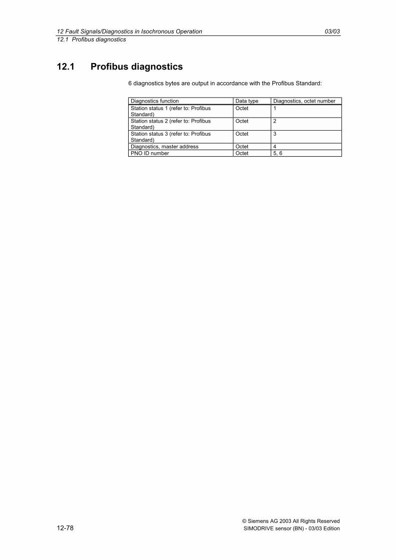
12 Fault Signals/Diagnostics in Isochronous Operation 03/0312.1 Profibus diagnostics
© Siemens AG 2003 All Rights Reserved12-78 SIMODRIVE sensor (BN) - 03/03 Edition
12.1 Profibus diagnostics6 diagnostics bytes are output in accordance with the Profibus Standard:
Diagnostics function Data type Diagnostics, octet numberStation status 1 (refer to: ProfibusStandard)
Octet 1
Station status 2 (refer to: ProfibusStandard)
Octet 2
Station status 3 (refer to: ProfibusStandard)
Octet 3
Diagnostics, master address Octet 4PNO ID number Octet 5, 6

03/03 12 Fault Signals/Diagnostics in Isochronous Operation12.2 Status signals using the LEDs in the connecting cover
© Siemens AG 2003 All Rights ReservedSIMODRIVE sensor (BN) - 03/03 Edition 12-79
12.2 Status signals using the LEDs in the connecting coverVarious (fault) states of the devices are displayed using the two LEDs in theconnecting cover:
No. Red LED GreenLED
Status signal / possible cause
1 Dark Dark Power supply missing2 Bright Bright The absolute value encoder is ready, but has still not
received configuration data after the power wasconnected.Possible causes: Incorrectly set address, bus cablesincorrectly connected
3 Bright Flashing Parameterizing or configuration errorThe absolute value encoder receives configuration orparameter data with the incorrect length orinconsistent data.Possible cause: e.g. the total resolution was set toohigh
4 Flashing Bright Absolute value encoder is ready, but has still notbeen addressed from the master.(e.g. the incorrect address is being used)
5 Bright Dark Absolute value encoder does not receive any data fora long period of time (approx. 40 seconds) (e.g. thedata line is interrupted)
6 Dark Bright Normal operation in the data exchange modus
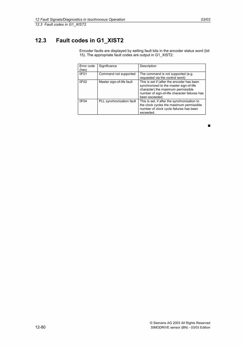
12 Fault Signals/Diagnostics in Isochronous Operation 03/0312.3 Fault codes in G1_XIST2
© Siemens AG 2003 All Rights Reserved12-80 SIMODRIVE sensor (BN) - 03/03 Edition
12.3 Fault codes in G1_XIST2Encoder faults are displayed by setting fault bits in the encoder status word (bit15). The appropriate fault codes are output in G1_XIST2:
Error code(hex)
Significance Description
0F01 Command not supported The command is not supported (e.g.requested via the control word)
0F02 Master sign-of-life fault This is set if (after the encoder has beensynchronized to the master sign-of-lifecharacter) the maximum permissiblenumber of sign-of-life character failures hasbeen exceeded.
0F04 PLL synchronization fault This is set, if after the synchronization tothe clock cycles the maximum permissiblenumber of clock cycle failures has beenexceeded.

© Siemens AG 2003 All Rights ReservedSIMODRIVE sensor (BN) - 03/03 Edition 13-81
Configuring Example for IsochronousOperation STEP 7
13.1 Reading-in the GSD file .....................................................................................13-82
13.2 Configuring the absolute value encoder ............................................................13-83
13.3 Telegram selection.............................................................................................13-84
13.4 Parameterization................................................................................................13-8513.4.1 Device-specific parameters................................................................................13-8513.4.2 Isochronous parameters ....................................................................................13-86
13

13 Configuring Example for Isochronous Operation STEP 7 03/0313.1 Downloading the GSD file
© Siemens AG 2003 All Rights Reserved13-82 SIMODRIVE sensor (BN) - 03/03 Edition
13.1 Downloading the GSD fileWhen used for the first time, the GSD file ("SIEM80F9.GSD") must be installedin order to include the absolute value encoder in the hardware catalog. In thiscase, the "Install new GSD.." item must be selected in the window "HW Config"of the SIMATIC Manager under the menu item "Options". The appropriate GSDfile ("SIEM80F9.GSD") should then be selected.The GSD file can be obtained from SIEMENS.
After the GSD file has been downloaded, the absolute value encoder appearsin the hardware Catalog under "PROFIBUS-DP" - "Other field devices" -"Encoder" - "SIMODRIVE sensor isochronous".

03/03 13 Configuring Example for Isochronous Operation STEP 713.2 Configuring the absolute value encoder
© Siemens AG 2003 All Rights ReservedSIMODRIVE sensor (BN) - 03/03 Edition 13-83
13.2 Configuring the absolute value encoder
After the Profibus network has been configured in the hardware configuratorunder the menu item "Insert" "Master system" the absolute value encodercan be selected from the hardware Catalog and inserted in the network. To dothis, the "SIMODRIVE sensor isochronous" device is coupled to the bus bydragging & dropping it (or by double clicking on the module with the busselected).
After the device has been inserted, the node address of the slave device isentered. This must match the address set in the connecting cover.

13 Configuring Example for Isochronous Operation STEP 7 03/0313.3 Telegram selection
© Siemens AG 2003 All Rights Reserved13-84 SIMODRIVE sensor (BN) - 03/03 Edition
13.3 Telegram selection
After the device was inserted, as described, in the Profibus network, thetelegram can now be selected. Currently, only telegram type 81 is supported.The module is dragged and dropped at slot 1 (table in the lower section of thestation [node] window).

03/03 13 Configuring Example for Isochronous Operation STEP 713.4 Parameterization
© Siemens AG 2003 All Rights ReservedSIMODRIVE sensor (BN) - 03/03 Edition 13-85
13.4 Parameterization
13.4.1 Device-specific parameters
The dialog box "DP slave properties" is displayed by double clicking on theencoder to be parameterized. The "parameterizing" table should be selected toenter parameters.
Various parameters of the device can be defined under (Device-specificparameter) (refer to 10.2).

13 Configuring Example for Isochronous Operation STEP 7 03/0313.4 Parameterization
© Siemens AG 2003 All Rights Reserved13-86 SIMODRIVE sensor (BN) - 03/03 Edition
13.4.2 Isochronous parameters
Initially, the "Equidistance" function should be configured in the Profibusnetwork (an appropriate master must be selected supports this functionality):
In the network view double click on the PROFIBUS sub-network.
After selecting the "Properties" button in the properties dialog box select the"Network settings" tab.
Select the "DP" profile and click on the "Options" button.
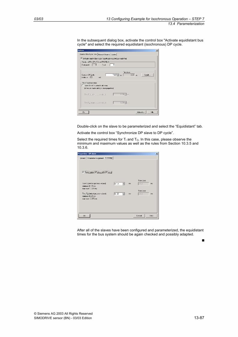
03/03 13 Configuring Example for Isochronous Operation STEP 713.4 Parameterization
© Siemens AG 2003 All Rights ReservedSIMODRIVE sensor (BN) - 03/03 Edition 13-87
In the subsequent dialog box, activate the control box "Activate equidistant buscycle" and select the required equidistant (isochronous) DP cycle.
Double-click on the slave to be parameterized and select the Equidistant tab.
Activate the control box Synchronize DP slave to DP cycle.
Select the required times for TI and TO. In this case, please observe theminimum and maximum values as well as the rules from Section 10.3.5 and10.3.6.
After all of the slaves have been configured and parameterized, the equidistanttimes for the bus system should be again checked and possibly adapted.

13 Configuring Example for Isochronous Operation STEP 7 03/0313.4 Parameterization
© Siemens AG 2003 All Rights Reserved13-88 SIMODRIVE sensor (BN) - 03/03 Edition
Space for your notes

© Siemens AG 2003 All Rights ReservedSIMODRIVE sensor (BN) - 03/03 Edition 14-89
Technical Data
14.1 Electrical data .......................................................................................................14-90
14.2 Mechanical data....................................................................................................14-91
14.3 Ambient conditions ...............................................................................................14-92
14.4 Dimension drawings .............................................................................................14-93
14
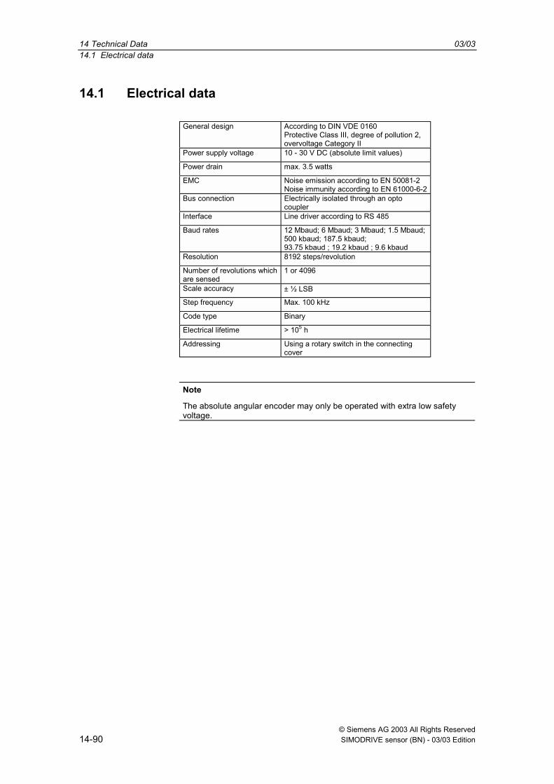
14 Technical Data 03/0314.1 Electrical data
© Siemens AG 2003 All Rights Reserved14-90 SIMODRIVE sensor (BN) - 03/03 Edition
14.1 Electrical data
General design According to DIN VDE 0160Protective Class III, degree of pollution 2,overvoltage Category II
Power supply voltage 10 - 30 V DC (absolute limit values)
Power drain max. 3.5 watts
EMC Noise emission according to EN 50081-2Noise immunity according to EN 61000-6-2
Bus connection Electrically isolated through an optocoupler
Interface Line driver according to RS 485
Baud rates 12 Mbaud; 6 Mbaud; 3 Mbaud; 1.5 Mbaud;500 kbaud; 187.5 kbaud;93.75 kbaud ; 19.2 kbaud ; 9.6 kbaud
Resolution 8192 steps/revolution
Number of revolutions whichare sensed
1 or 4096
Scale accuracy ± ½ LSB
Step frequency Max. 100 kHz
Code type Binary
Electrical lifetime > 105 h
Addressing Using a rotary switch in the connectingcover
Note
The absolute angular encoder may only be operated with extra low safetyvoltage.

03/03 14 Technical Data14.2 Mechanical data
© Siemens AG 2003 All Rights ReservedSIMODRIVE sensor (BN) - 03/03 Edition 14-91
14.2 Mechanical data
Housing Aluminum
Flange Synchronous flange Clamping flange
Shaft diameter 6 mm 10 mm
Shaft length 10 mm 20 mm
Shaft loading Axial 20 N, radial 110 N
Friction torque ≤ 5 Ncm
Rotor moment of inertia ≈ 50 gcm2
Lifetime > 105 h at 1000 RPM
Speed 6000 RPM (continuous operation)
Shock immunity (EN 60068-2-27) ≤ 100 g (half sine, 6 ms)
Continuous shock immunity(EN 60028-2-29)
≤ 10 g (half sine, 16 ms)
Vibration immunity (EN 60068-2-6) ≤ 10 g (10 Hz ... 1000 Hz)
Connection Connecting cover with terminal strip as Tdistributor
Weight (incl. connecting cover) Single-turnMulti-turn
Approx. 500 gApprox. 700 g
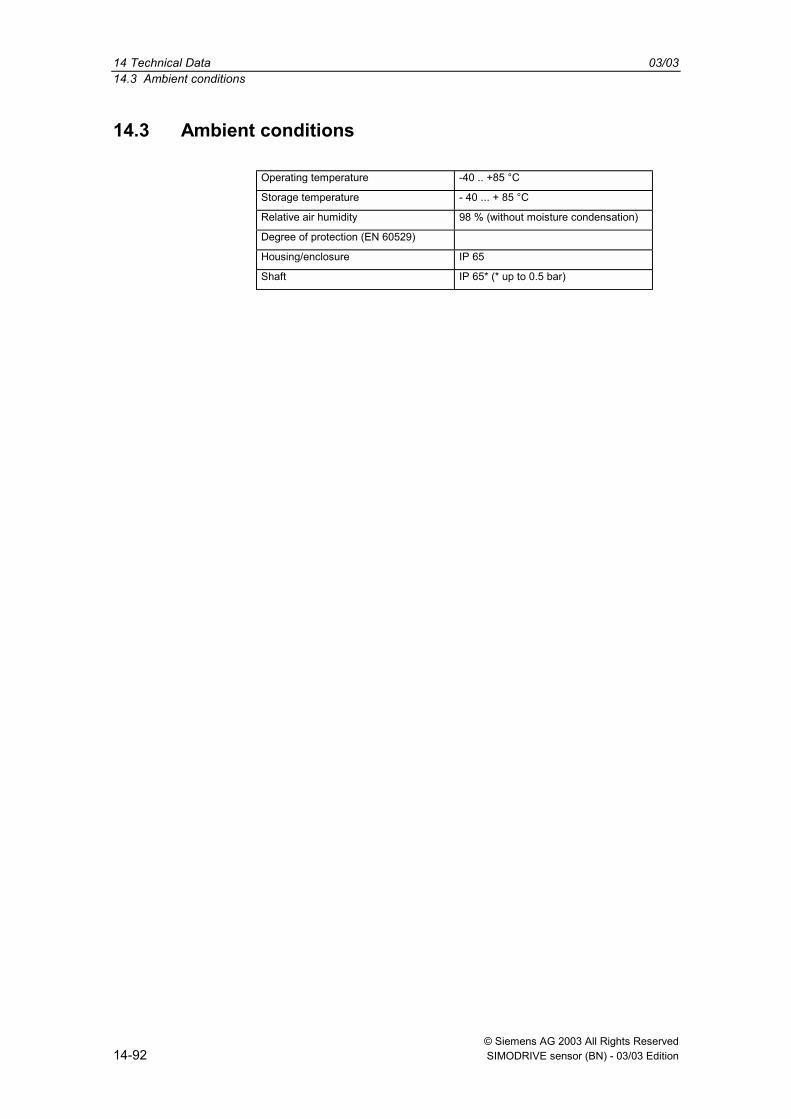
14 Technical Data 03/0314.3 Ambient conditions
© Siemens AG 2003 All Rights Reserved14-92 SIMODRIVE sensor (BN) - 03/03 Edition
14.3 Ambient conditions
Operating temperature -40 .. +85 °C
Storage temperature - 40 ... + 85 °C
Relative air humidity 98 % (without moisture condensation)
Degree of protection (EN 60529)
Housing/enclosure IP 65
Shaft IP 65* (* up to 0.5 bar)
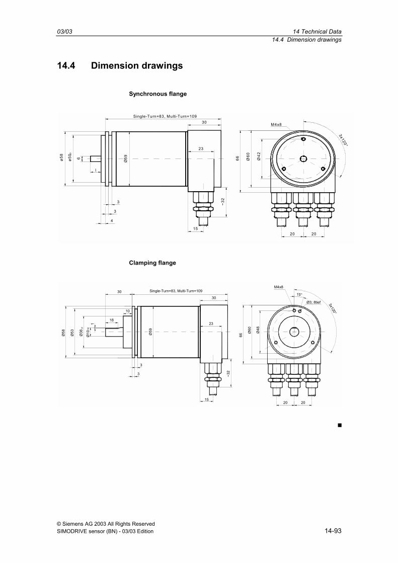
03/03 14 Technical Data14.4 Dimension drawings
© Siemens AG 2003 All Rights ReservedSIMODRIVE sensor (BN) - 03/03 Edition 14-93
14.4 Dimension drawings
Synchronous flange
Single-Turn=83, Multi-Turn=109
~32
Ø60
Ø42
M4x8
3x120°
ø50ø58
f7
Ø59
23
30
15
66
4
3
3
l
20 20
6
Clamping flange
1
30
Ø10
h8f7
3
Ø60
Ø48
M4x8Single-Turn=83, Multi-Turn=109
~32
Ø59
23
30
Ø58
Ø53
Ø36
66
15
3
10
18
Ø3; 8tief 3x120°
15°
20 20

14 Technical Data 03/0314.4 Dimension drawings
© Siemens AG 2003 All Rights Reserved14-94 SIMODRIVE sensor (BN) - 03/03 Edition
Space for your notes
© Siemens AG 2003 All Rights ReservedSIMODRIVE sensor (BN) - 03/03 Edition 15-95
Appendix
15.1 Additional encoder classes ................................................................................15-9615.1.1 Version 2.0 multi-turn.........................................................................................15-9615.1.2 Version 1.1 multi-turn.........................................................................................15-9615.1.3 Version 1.0 multi-turn.........................................................................................15-96
15.2 FAQ Absolute value encoders, Profibus ............................................................15-97
15.3 Terminology .......................................................................................................15-99
15
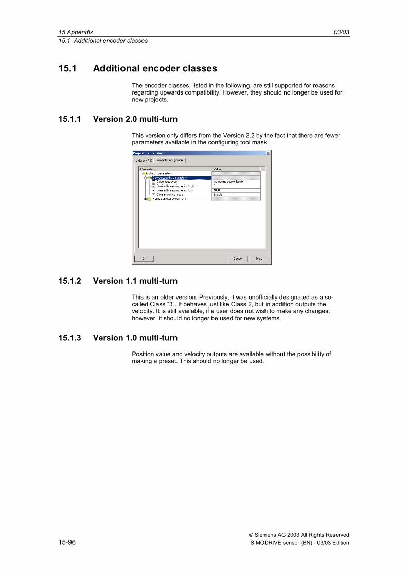
15 Appendix 03/0315.1 Additional encoder classes
© Siemens AG 2003 All Rights Reserved15-96 SIMODRIVE sensor (BN) - 03/03 Edition
15.1 Additional encoder classesThe encoder classes, listed in the following, are still supported for reasonsregarding upwards compatibility. However, they should no longer be used fornew projects.
15.1.1 Version 2.0 multi-turn
This version only differs from the Version 2.2 by the fact that there are fewerparameters available in the configuring tool mask.
15.1.2 Version 1.1 multi-turn
This is an older version. Previously, it was unofficially designated as a so-called Class 3. It behaves just like Class 2, but in addition outputs thevelocity. It is still available, if a user does not wish to make any changes;however, it should no longer be used for new systems.
15.1.3 Version 1.0 multi-turn
Position value and velocity outputs are available without the possibility ofmaking a preset. This should no longer be used.

03/03 15 Appendix15.2 FAQ Absolute value encoders, Profibus
© Siemens AG 2003 All Rights ReservedSIMODRIVE sensor (BN) - 03/03 Edition 15-97
15.2 FAQ Absolute value encoders, Profibus
Problem
When using one of the following Profibus masters and for encoder classeshigher than Class 1, problems occur when running-up the system (bus fault,encoder does not log-on):
− SIEMENS S5-95U
− Master interface SIEMENS IM 308-B
− Softing PROFIboard
− Allen Bradley 1785 PFB/B
− Mitsubishi A1SJ 71PB92D
Possible cause
Under certain circumstances, the master does not support the full number ofdiagnostic bytes (57 bytes) provided by the absolute value encoder.
Remedy
If possible, the maximum number of diagnostics data per slave should beincreased in the master.
If this is not possible, then the absolute value encoder can either be used asClass1 device (16 diagnostic bytes) or one of the manufacturer-specificClasses is selected (Version 2.1 or 2.2) and "Reduced diagnostics" is enabledin the parameterization (refer to Section 5.1.5).
Problem
For COM PROFIBUS Version 5.0, the absolute value encoder cannot beconfigured together with the S5-95U.
Cause
The S5-95U does not support the full complement of diagnostics data (57bytes).
For COM Profibus V5.0, the GSD entry "Max_Diag_Data_Len=57" is checkedand it is prevented from configuring together with the S5-95U.
Remedy
Use COM Profibus Version 3.3, select one of the manufacturer-specificClasses (Version 2.1 or 2.2) and activate the shortened diagnostics(parameter).
It is only possible to use the device with COM Profibus V5.0 using a modifiedGSD file (the slave key "Max_Diag_Data_Len" must be modified).

15 Appendix 03/0315.2 FAQ Absolute value encoders, Profibus
© Siemens AG 2003 All Rights Reserved15-98 SIMODRIVE sensor (BN) - 03/03 Edition
Problem
PLC and master interface are switched-in, the bus is active, but the absolutevalue encoder does not log-on.
Remedy
To start, check the state of the LEDs in the connecting cover (refer to Section6.3); under certain circumstances, information can be obtained about thepossible fault causes.
Both LEDs dark: Check the power supply!
Both LEDs bright:The device is not receiving parameters and configuration data. Check theaddress setting in the connecting cover. Check that the bus lines (cables) arecorrectly connected (BUS IN/BUS OUT). Check the configuring.
Red LED bright, green LED flashing:Parameter error! Check the parameterization: e.g. total resolution (refer to4.2.6)
Problem
Bus faults sporadically occur.
Possible cause
The terminating resistors are not correct
Remedy
Check the terminating resistors!
The 220 Ω terminating resistor must be switched-in at the beginning and at theend of the bus segment. Measure the resistance between the two data lines!To do this, the power supply must be powered-down and a measurementmade between connections "A" and "B" in the connecting cover. The measuredresistance value must be approx. 110 Ω (220 Ω parallel 220 Ω).
Possible causes
EMC problems
Remedy
Check as to whether the selected baud rate is permissible for the cable length;if required, use a lower baud rate. Check the connecting cover that it iscorrectly located and ensure that the cables have been correctly routedregarding EMC.

03/03 15 Appendix15.3 Terminology
© Siemens AG 2003 All Rights ReservedSIMODRIVE sensor (BN) - 03/03 Edition 15-99
15.3 Terminology
Terminating resistor Resistor to adapt bus cables; terminating resistors are alwaysrequired at the end of a cable or segment.
Address A number, which is assigned to each node, no matterwhether it is a master or slave. The setting is realized in theconnecting cover using rotary switches so that it is non-volatile.
Baud rate Data transfer rate specified as the number of bits transferredper second (baud rate = bit rate).
Bus node Device, which can send, receive or amplify data via the bus.
Configuring When configuring, the master signals the angular encoderhow it is to behave, e.g. the number of input and outputwords.(also refer to DDLM_Set_Prm).
DDLM Direct Data Link Mapper. Interface between Profibus-DPfunctions and the encoder software.
DDLM_Data_Exchange Operating status of the bus, for standard data transfer.
DDLM_Set_Prm Operating status of the bus, in which configuration data issent.
DDLM_Slave_Diag Operating status of the bus, in which diagnostics data arerequested from the slave (e.g. absolute value encoder).
DP Distributed peripherals
Diagnostics Identification, localization, classification, display, additionalevaluation of faults, errors and messages.
Encoder Alternative designation for (angular) encoders or absolutevalue encoders
Freeze This is a master command to the slave. This allows themaster to freeze the statuses of the inputs to theirinstantaneous value. The input data are only updated again,when the master sends the UNFREEZE command.
GSD file Master device data file, in which the slave-specific propertiesand characteristics are defined. The GSD is a file, which ismade available for most Profibus nodes (stations) by themanufacturer. The GSD formats are unified, so that thecorresponding control software can access it. (also refer to Type file).
Master Bus nodes, which can send data on their own initiative, anddefine which slave should send data. Slave
Octet Data unit of 8 bits = 1 byte
Parameterization Transfers specific values (such as resolution per revolution,direction of rotation, etc.) from the master to the slave (in thiscase: absolute value encoder).This is realized when the system runs-up.
Profibus Process Fieldbus, European fieldbus standard, which isdefined in the PROFIBUS Standard. This specifies functional,electrical and mechanical characteristics for a bit-serialfieldbus system.
Slave Bus node, which essentially only sends data when instructedto do so by the Master. Absolute value encoders arealways slaves.
Type file Similar to a GSD file is used by olderengineering/configuring tools.
Word Is frequently used, but not in a unified fashion, for a data unitof 2 bytes.

15 Appendix 03/0315.3 Terminology
© Siemens AG 2003 All Rights Reserved15-100 SIMODRIVE sensor (BN) - 03/03 Edition
Space for your notes

© Siemens AG 2003 All Rights ReservedSIMODRIVE sensor (BN) - 03/03 Edition 16-101
Index
Class 1 23Class 2 23Commissioning mode 40Configuration 51Connecting cover
LEDs 48Settings 13
Connecting-up the signal andpower supply cables 15
Connection coverWiring 16
Data format 22Device class
Selecting 52Dimension drawings 93Direction of rotation 27Encoder classes 21
Additional 96Encoder profile 10Endless axis 28FAQ 97GSD file 99
Reading in 50
Installation 11Memory error 45Node 13Node address 13Operating time alarm 46Parameterization 53physical measuring steps 34Physical measuring steps 32, 37Preset function 30Profibus User Organization 10Reduced diagnostics 35Required measuring steps 33Rotary axis 28Software limit switch 36Status bits 39STEP 7 49Stopping teach-in 42Teach-in start 41Terminating resistors 13Total resolution 28Type file 99Velocity
Dimension units 38
16

16 Index 03/03
© Siemens AG 2003 All Rights Reserved16-2 SIMODRIVE sensor (BN) - 03/03 Edition
Space for your notes
Siemens AGSuggestions
Corrections
A&D MC BMSPostfach 3180
For Publication/Manual:
SIMODRIVE sensor
D-91050 ErlangenTel.: +49 (0)180 / 5050-222 [Hotline]Fax: +49 (0)9131 / 98-2176 [Documentation]eMail: [email protected]
Absolute Value Encoder with PROFIBUS-DP
Manufacturer Documentation
From
Name:
User Manual
Order No.: 6SN 1197-0AB10-0YP2Edition: 03/03
Company/Department
Address:
Telephone: __________ /
Telefax: ________ /
Should you come across any printing errorswhen reading this publication, please notifyus on this sheet.Suggestions for improvement are alsowelcome.
Suggestions and/or corrections

Siemens AGAutomatisierungs- und AntriebstechnikMotion Control SystemsPostfach 3180, D – 91050 ErlangenBundesrepublik Deutschland
www.ad.siemens.de
© Siemens AG 2003Subject to change without prior notice
Order No.: 6SN1197-0AB10-0YP2
Printed in the Federal Republic of Germany