user interface for intel® sata motherboard signal quality ... · pdf filemotherboard...
TRANSCRIPT
323096
User Interface for
Intel® SATA
Motherboard
Signal Quality Test
(MSQT) Setup December, 2009
White Paper
Soo Jin Tan
Technical Marketing Engineer
Intel Corporation

User Interface for SATA MSQT Setup
2
Executive Summary This paper introduces an alternative way o f how to modify and setup the
AHCI registers for the SATA MSQT to decrease setup time and increase
accuracy in setting bits and registers.
Different from the conventional way, this method uses a user interface
which performs the registers setup without any register mapping tools
such as ITP, PCIe.exe, etc.
The benefits of this method include: Fast and easy setup,
automatic setup, greater accuracy in setting bits and registers,
no mapping tool is required no Datasheet or PDG is needed, and
it can save up to 50% of the test time.
With codes running on the background, user’s selection or instruction will
be executed by the codes and perform the setups automatically. There
are no more manual configurations and settings that need to be done.
The only action the user needs to complete is to launch the executable file
(.EXE) and select the desired test.
The Intel® Embedded Design Center provides qualified developers with
web-based access to technical resources. Access Intel Confidential design
materials, step-by step guidance, application reference solutions, training,
Intel’s tool loaner program, and connect with an e-help desk and the
embedded community. Design Fast. Design Smart. Get started today.
www.intel.com/embedded/edc. §
User Interface for Intel® SATA MSQT Setup
3
Contents
Background ............................................................................................................. 4
Solution .................................................................................................................. 4
Procedures for SATA MSQT Execution ........................................................................ 5
Conventional Way of SATA Controller Configuration and Test Mode Setup ...................... 8
User Interface of SATA Controller Configuration and Test Mode Setup ......................... 10
Step A – Enable the SATA Controller ...................................................... 10
Step B – Select Ports to Run at Gen 1/Gen 2 Speed ................................ 11
Step C – Select Port to Run and Begin the Test ....................................... 11
Conclusion ............................................................................................................ 13

323096
Background
SATA MSQT has been a very crucial validation methodology to measure the signal quality of the SATA differential pairs. It has been widely adopted for
SATA port testing ever since the existence of ICH5. The SATA motherboard signal quality is gauged by measuring transmissions as close as possible to the SATA connector on the motherboard. The data is captured into an eye diagram for analysis and compared against an eye diagram template that reflects the expected SATA interface characteristics for the given speed. By performing analysis in this way, worst case device and cable effects are built into the eye diagram template, thus removing characteristics of the actual
cable and device which may not be worst case per the SATA Specification. Total jitter can also be used to analyze the characteristics of the SATA interface. The tests performed are transmit only and measured using a SATA Test Fixture.
Intel strongly recommends running the MSQT procedure since the SATA
interface is a high-speed interface with Gen 1 and Gen 2 running at 1.5Gb/s and 3.0Gb/s respectively.
However, before running the test, there are many procedures that need to go through especially modifying all the registers to setup the test environment. These have been very troublesome and always become the
show stopper. Customer will usually require an ITP or other register mapping tools to be able to access and modify the relevant registers one by one before the test can be fully executed.
Solution
In this whitepaper, we are going to introduce an user interface which provides the step-by-step registers setup AUTOMATICALLY without using any registers mapping tools. With only few clicks, the ICHx or PCH SATA
Controller can be configured and easily put into Test Mode in the background. With this automatic setup, the user is not required to figure out what the base addresses are, how to add the offset, and make changes to the bits again and again. Without this program, all these tasks have to be done manually.
Using a platform featuring the Intel® EP80579 Integrated Processor as the reference, this paper will show how the program modifies the registers under your instructions in the user interface format. The source code of the
User Interface for Intel® SATA MSQT Setup
5
program can be proliferated further for different platforms for the SATA
MSQT.
Procedures for SATA MSQT Execution
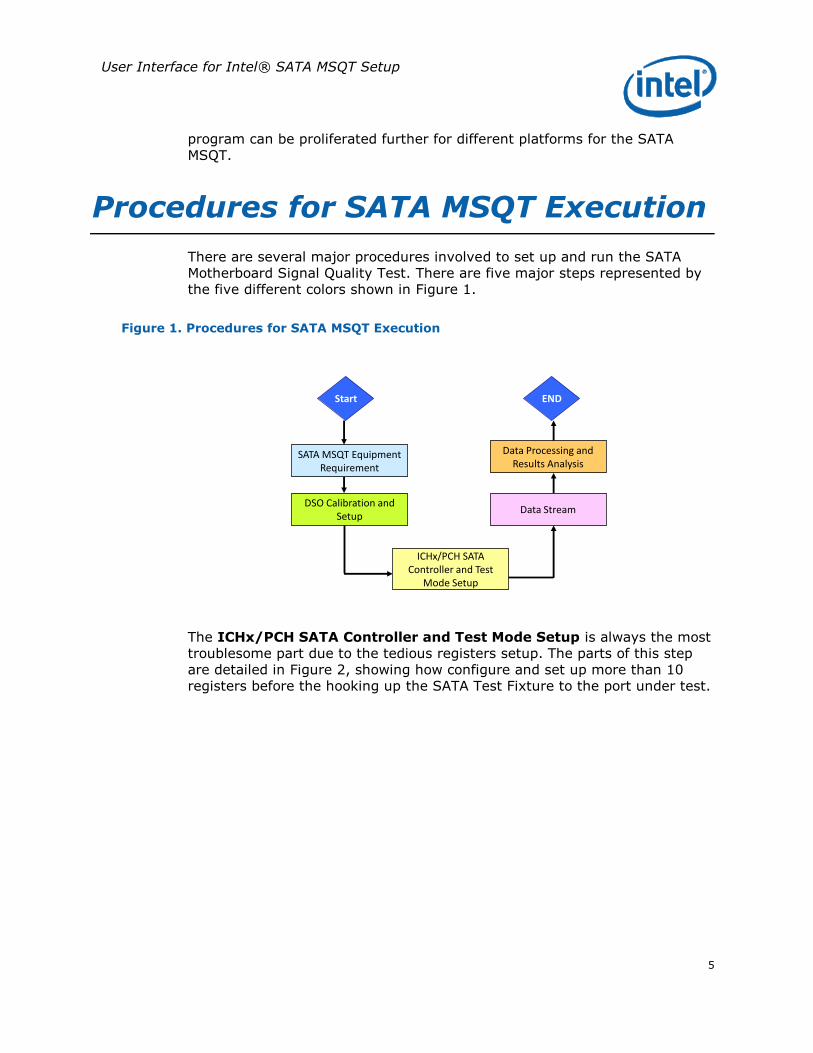
There are several major procedures involved to set up and run the SATA Motherboard Signal Quality Test. There are five major steps represented by the five different colors shown in Figure 1.
Figure 1. Procedures for SATA MSQT Execution
SATA MSQT Equipment Requirement
Start
DSO Calibration and Setup
ICHx/PCH SATA Controller and Test
Mode Setup
Data Stream
Data Processing and Results Analysis
END
The ICHx/PCH SATA Controller and Test Mode Setup is always the most troublesome part due to the tedious registers setup. The parts of this step
are detailed in Figure 2, showing how configure and set up more than 10 registers before the hooking up the SATA Test Fixture to the port under test.

User Interface for SATA MSQT Setup
6
Figure 2. Steps in ICHx/PCH SATA Controller and Test Mode Setup
Enable the SATA Controller
Disable All Ports
Enable Each Port Separately for Speed Selection
Set Each Port to Run at Gen 1/Gen 2
Put the SATA Controller into Test Mode
Enable Each Port One-by-one to Run the Test
1
2
3
4
5
6
Step 1, Enable the SATA Controller, requires several substeps to complete. These substeps are detailed in Figure 3.

User Interface for Intel® SATA MSQT Setup
7
Figure 3. Enable the SATA Controller
Bits [11:0] are don’t care and 000h should
be used
Check Base Address from PCI Dev 31, Func
0, Offset F0h
Base Address:FED1 Cxxx -> FED1 C000h
Ex.
Add Offset 3418h to Base Address
Base Address:FED1 C000h + 3418h =
FED1 F418h
Ex.
Bit 2 of the value should be 0
FED1 F418h = xxxx x0xxb
Ex.
YES. SATA controller is enabled

User Interface for SATA MSQT Setup
8
Conventional Way of SATA Controller
Configuration and Test Mode Setup
Conventionally, these steps are done manually using some legacy tools:
PCITool
ITP-XDP
PCI.exe
WinMem.exe
EFI Shell and etc
Figure 4, Figure 5 and Figure 6 show screenshots of these tools. In addition to the manual steps needed to complete the test using these tools, mathematical additions shown in Figure 3 still need to be done separately as
these tools do not complete the calculations automatically.
Figure 4. PCITool in ITP-XDP

User Interface for Intel® SATA MSQT Setup
9
Figure 5. WinMem
Figure 6. PCI.exe
Figure 7. EFI Shell Command

User Interface for SATA MSQT Setup
10
User Interface of SATA Controller
Configuration and Test Mode Setup
Now, with the newly introduced user interface with simplified steps, all these configurations can be done faster more and more efficiently. Compared to the conventional method of more than 10 steps, the new methodology has now simplified them to only three by using a user interface.
Figure 8. Conventional versus New
Enable the SATA Controller
Disable All Ports
Enable Each Port Separately for Speed Selection
Set Each Port to Run at Gen 1/Gen 2
Put the SATA Controller into Test Mode
Enable Each Port One-by-one to Run the Test
1
6
Conventional New
Enable SATA Controller
Select Ports to Run at Gen 1/Gen 2
Select Port to Run and Begin the Test
A
B
C
2
3
4
5
Step A – Enable the SATA Controller
Instead of going through all the conventional steps mentioned on Figure 3 to
enable the SATA Controller, now the steps can easily be done with just few clicks with this user interface!
As shown Figure 9, users will just need to enter “1” to enable the SATA Controller within Intel® EP80579 Integrated Processor or the Intel® 82801GX I/O Controller Hub.

User Interface for Intel® SATA MSQT Setup
11
Figure 9. User Interface - Enable the SATA Controller
Enable SATA Controller
Select Ports to Run at Gen 1/Gen 2
Select Port to Run and Begin the Test
A
B
C
Step B – Select Ports to Run at Gen 1/Gen 2
Speed
After this step, the program will automatically complete steps 2, 3 and 4 from the manual process as shown in Figure 8.
In this screen, users can either enter “1” or “2” to select the speed to test.
Figure 10. User Interface - Select Ports to Run at Gen 1/Gen 2
Enable SATA Controller
Select Ports to Run at Gen 1/Gen 2
Select Port to Run and Begin the Test
A
B
C
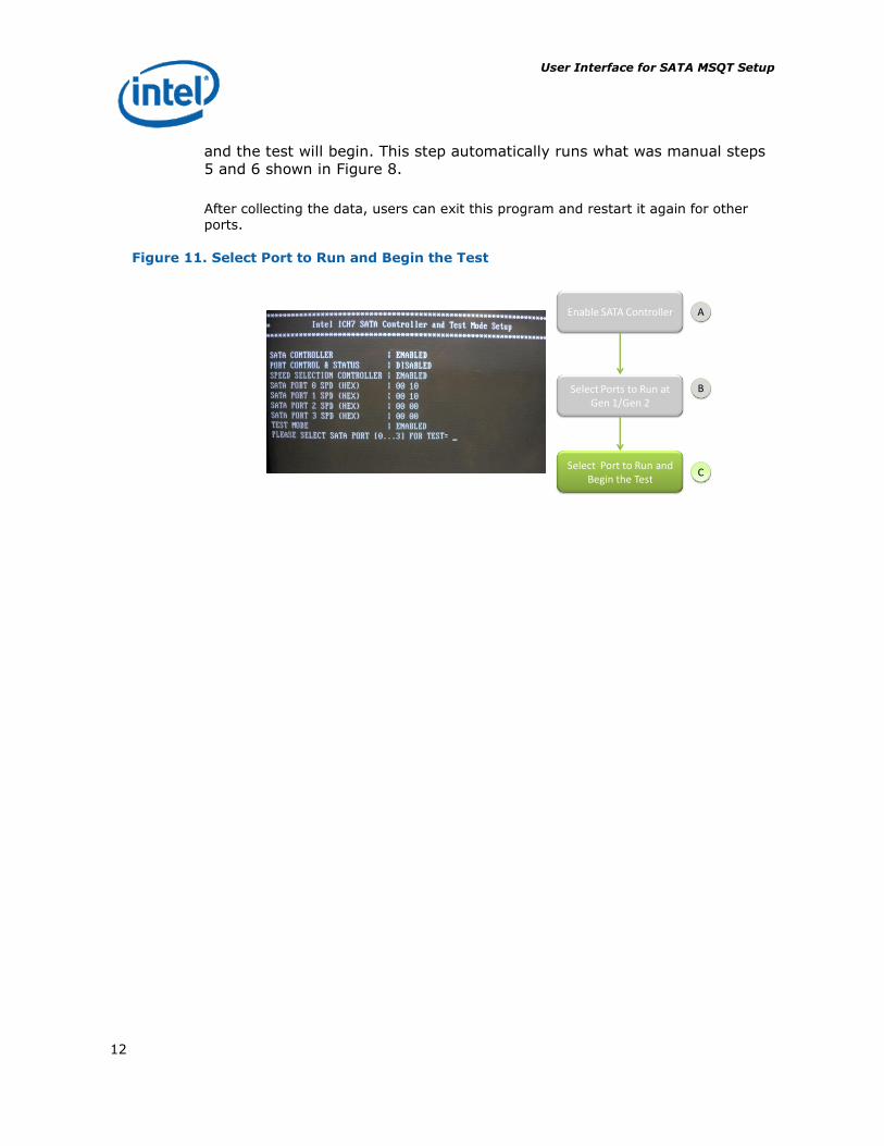
Step C – Select Port to Run and Begin the Test
Next, the screen which allows users to select which port to run will pop up. For the 82801GX I/O CONTROLLER HUB, there are four SATA ports available and for the Intel® EP80579 Integrated Processor, there are two SATA ports available. Users can select which port to run by entering the port number
User Interface for SATA MSQT Setup
12
and the test will begin. This step automatically runs what was manual steps
5 and 6 shown in Figure 8.
After collecting the data, users can exit this program and restart it again for other ports.
Figure 11. Select Port to Run and Begin the Test
Enable SATA Controller
Select Ports to Run at Gen 1/Gen 2
Select Port to Run and Begin the Test
A
B
C

User Interface for Intel® SATA MSQT Setup
13
Conclusion
With SATA 2.0 running at the speed of 3 Gbps, the SATA MSQT plays a vital role to ensure the signal integrity of the high speed signals. With SATA 3.0
targeted to run at 6 Gbps, this test is getting more and more significant to ensure the robustness and the validity of data. Thus, a more simplified and efficient methodology must be introduced to decrease the complexity of running the test.
As explained in the earlier chapters, the new methodology has done all that
is required to effectively test the signal. By simplifying steps of configuration and creating a user friendly interface, this test is more efficient and more effective by using the user interface method.

User Interface for SATA MSQT Setup
14
The Intel® Embedded Design Center provides qualified developers with web-based access to technical resources. Access Intel Confidential design materials, step-by step guidance, application reference solutions, training, Intel’s tool loaner program, and connect with an e-help desk and the embedded community. Design Fast. Design Smart. Get started today. http://intel.com/embedded/edc.
Authors
Soo Jin Tan is a Technical Marketing Engineer with Embedded Communication Group at Intel Corporation.
INFORMATION IN THIS DOCUMENT IS PROVIDED IN CONNECTION WITH INTEL® PRODUCTS. NO LICENSE, EXPRESS OR IMPLIED, BY ESTOPPEL OR OTHERWISE, TO ANY INTELLECTUAL PROPERTY RIGHTS IS GRANTED BY THIS DOCUMENT. EXCEPT AS PROVIDED IN INTEL’S TERMS AND CONDITIONS OF SALE FOR SUCH PRODUCTS, INTEL ASSUMES NO LIABILITY WHATSOEVER, AND INTEL DISCLAIMS ANY EXPRESS OR IMPLIED WARRANTY, RELATING TO SALE AND/OR USE OF INTEL PRODUCTS INCLUDING LIABILITY OR WARRANTIES RELATING TO FITNESS FOR A PARTICULAR PURPOSE, MERCHANTABILITY, OR INFRINGEMENT OF ANY PATENT, COPYRIGHT OR OTHER INTELLECTUAL PROPERTY RIGHT. Intel products are not intended for use in medical, life saving, or life sustaining applications.
Intel may make changes to specifications and product descriptions at any time, without notice.
This paper is for informational purposes only. THIS DOCUMENT IS PROVIDED "AS IS" WITH NO
WARRANTIES WHATSOEVER, INCLUDING ANY WARRANTY OF MERCHANTABILITY,
NONINFRINGEMENT, FITNESS FOR ANY PARTICULAR PURPOSE, OR ANY WARRANTY OTHERWISE
ARISING OUT OF ANY PROPOSAL, SPECIFICATION OR SAMPLE. Intel disclaims all liability, including
liability for infringement of any proprietary rights, relating to use of information in this specification.
No license, express or implied, by estoppel or otherwise, to any intellectual property rights is granted
herein.
BunnyPeople, Celeron, Celeron Inside, Centrino, Centrino logo, Core Inside, Dialogic, FlashFile, i960,
InstantIP, Intel, Intel logo, Intel386, Intel486, Intel740, IntelDX2, IntelDX4, IntelSX2, Intel Core, Intel
Inside, Intel Inside logo, Intel. Leap ahead., Intel. Leap ahead. logo, Intel NetBurst, Intel NetMerge,
Intel NetStructure, Intel SingleDriver, Intel SpeedStep, Intel EP80579 Integrated Processor, Intel
StrataFlash, Intel Viiv, Intel vPro, Intel XScale, IPLink, Itanium, Itanium Inside, MCS, MMX, Oplus,
OverDrive, PDCharm, Pentium, Pentium Inside, skoool, Sound Mark, The Journey Inside, VTune,
Xeon, and Xeon Inside are trademarks or registered trademarks of Intel Corporation or its
subsidiaries in the U.S. and other countries.
*Other names and brands may be claimed as the property of others.
Copyright © 2008 Intel Corporation. All rights reserved.