user instructions for toptronic rs-10ersatzteilkatalog.hoval.com/dvsfiles/0308020232drw... · if...
TRANSCRIPT

User Instructions For TopTronic® RS-10 430293ENG-Dec01
Hoval Ltd Northgate Newark Nottinghamshire NG24 1JN Phone 01636 672711 Fax 01636 673532
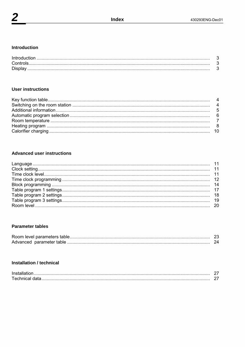
2 Index 430293ENG-Dec01 Introduction Introduction ....................................................................................................................................... 3 Controls............................................................................................................................................. 3 Display .............................................................................................................................................. 3 User instructions Key function table.............................................................................................................................. 4 Switching on the room station ........................................................................................................... 4 Additional information........................................................................................................................ 5 Automatic program selection ............................................................................................................. 6 Room temperature ............................................................................................................................ 7 Heating program ............................................................................................................................... 8 Calorifier charging ............................................................................................................................. 10 Advanced user instructions Language .......................................................................................................................................... 11 Clock setting...................................................................................................................................... 11 Time clock level................................................................................................................................. 11 Time clock programming ................................................................................................................... 12 Block programming ........................................................................................................................... 14 Table program 1 settings................................................................................................................... 17 Table program 2 settings................................................................................................................... 18 Table program 3 settings................................................................................................................... 19 Room level ........................................................................................................................................ 20 Parameter tables Room level parameters table............................................................................................................. 23 Advanced parameter table ............................................................................................................... 24 Installation / technical Installation......................................................................................................................................... 27 Technical data................................................................................................................................... 27

430293ENG-Dec01 Introduction 3 The TopTronic RS-10 room station serves as a decentralized information center with remote interrogation and remote operating functions and can be used with all equipment versions of the TopTronic system. With the most up to date micro electronics exclusive functions can be activated which guarantee the highest level of comfort with the minimum energy usage. This is achieved with adaption and optimization functions which match heating energy to the exact building requirements. As well as these room temperature related functions a variety of equipment specific information is available which can be read within the living room and when necessary adapted to individual circumstances. This encompasses dates, on/off switching of the heating cycle with differently regulated room temperatures, actual values and diagnostic fault messages of the boiler. Operation of the unit is easy to understand and is limited to a minimum of operating elements which are separated for user and advanced user levels. The instructions are separated into two parts. Part 1 (user instructions) delivers all immediately important operating stages which are necessary for use and are selected with directly accessible operating keys. Part 2 (advanced instructions) these should only be used by the advanced user or service engineer and relate to specific settings / heating parameters and are accessible by the covered operating keys. Controls 1 4 2 5 3 6 7 10 12 11 13 8 9 1 � LCD Display 2 � Key (increase value) 3 � Key (decrease value) 4 � Key for heating program 5 � Key for reduced (night time) program 6 � Information 7 � Program key (time/date) 8 � Program key (automatic programs) 9 � Program key (house level) 10 � Program key (service level) 11 � Forward key 12 � Backward key 13 � Cover
Symbol Display Heating Night setback Clock signal Room temperature

4 User Instructions 430293ENG-Dec01
Key Function table (User Level)
Function Enter with keys Adjust with keys / range Page No.
Room temperature correction
or
or
5�30oC 7
Heating (day) room temperature
or with
or
5�30oC 7
Reduced (night) room temperature
or with
or
5�30oC 7
Information 5
Party function
press and hold or
0.5�10h 8
Continuous heating
press and hold
or
5�30oC 8
Absent function
press and hold or
0.5�10h 9
Continuous reduced
press and hold or
5�30oC 9
Automatic
or 8-9
Calorifier charging
and
simultaneously
ON or
OFF 10
Automatic programs 1-3 and
simultaneously
or
1, 2, 3 6
Switching on the Room station When the room station is first switched on the following display will show for 5 seconds: Room Station Software version Central unit s Software version The default display will then appear. The symbol indicates that the room station is in heating operation and the symbol indicates the room station is in reduced (night time) operation.
Information: Monday 10th March 1997 Time 20.15 Room temperature 20.5oC Clock synchronisation
Attention:
• During summer switch off the following symbols are not shown and .
• Blinking symbols or indicate that the unit is not operating under a normal program eg. party.
• The symbol indicates that a radio clock synchronisation has been connected.
i

430293ENG-Dec01 User Instructions 5
Additional Information The following additional information on the central TopTronic can be obtained by pressing the button (only if the relevant sensors are fitted):
Default display.
External sensor 1 temperature.
External sensor 2 temperature.
Boiler temperature.
Mixed circuit 1 temperature.
Mixed circuit 2 temperature.
Domestic hot water temperature.
If the calorifier is fitted with a thermostat instead of a sensor the following will be displayed:
Calorifier on/off.
Boiler flue gas temperature.
Boiler return temperature.
External heat source temperature.
Default display.
Additional information with TopTronic 1B or 133B connected
Switch off operation: switch off at outside sensor (short circuit) or no signal for
outside temp. When the unit is switched off the information below shows instead of the default display.
System off � system switched off completely with no frost protection.
Further automatic information also appears:
Indication of forced standby operation by telephone modem. Indication of common fault (when outside sensor 2 is in short circuit in central unit)
Fault Indications The RS-10 room station has a comprehensive fault indication system which has priority over all other indications and remain active until the fault is rectified.
i
i
i
i
i
i
i
i
i
i
i
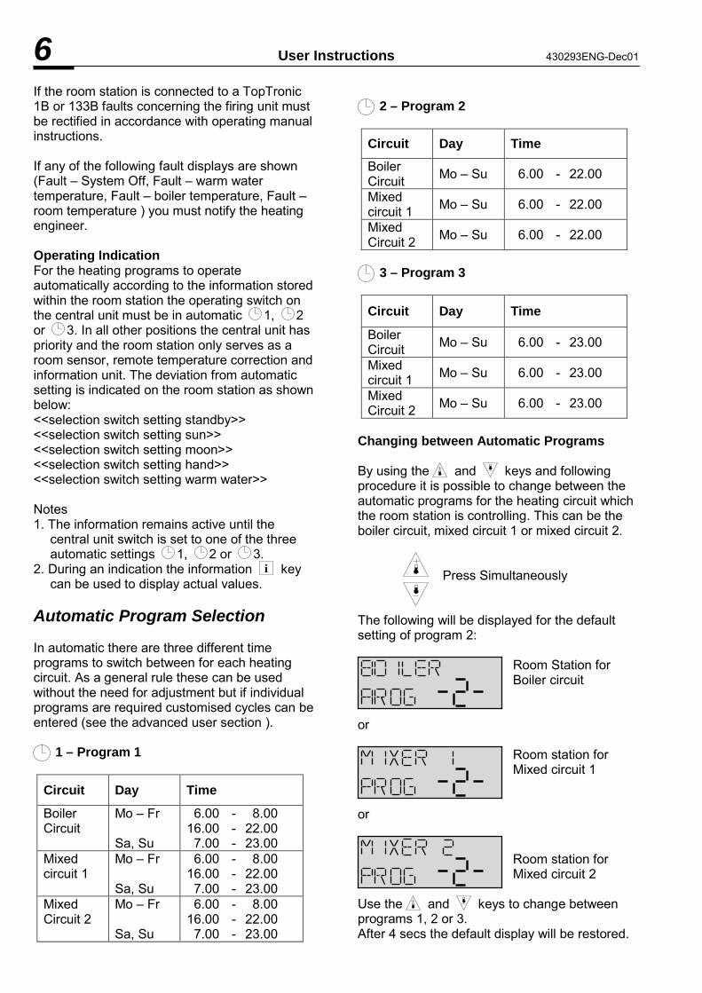
6 User Instructions 430293ENG-Dec01 If the room station is connected to a TopTronic 1B or 133B faults concerning the firing unit must be rectified in accordance with operating manual instructions. If any of the following fault displays are shown (Fault � System Off, Fault � warm water temperature, Fault � boiler temperature, Fault � room temperature ) you must notify the heating engineer. Operating Indication For the heating programs to operate automatically according to the information stored within the room station the operating switch on the central unit must be in automatic 1, 2 or 3. In all other positions the central unit has priority and the room station only serves as a room sensor, remote temperature correction and information unit. The deviation from automatic setting is indicated on the room station as shown below: <<selection switch setting standby>> <<selection switch setting sun>> <<selection switch setting moon>> <<selection switch setting hand>> <<selection switch setting warm water>> Notes 1. The information remains active until the
central unit switch is set to one of the three automatic settings 1, 2 or 3.
2. During an indication the information key can be used to display actual values.
Automatic Program Selection In automatic there are three different time programs to switch between for each heating circuit. As a general rule these can be used without the need for adjustment but if individual programs are required customised cycles can be entered (see the advanced user section ). 1 – Program 1
Circuit Day Time
Boiler Circuit
Mo � Fr Sa, Su
6.00 - 8.00 16.00 - 22.00 7.00 - 23.00
Mixed circuit 1
Mo � Fr Sa, Su
6.00 - 8.00 16.00 - 22.00 7.00 - 23.00
Mixed Circuit 2
Mo � Fr Sa, Su
6.00 - 8.00 16.00 - 22.00 7.00 - 23.00
2 – Program 2
Circuit Day Time Boiler Circuit Mo � Su 6.00 - 22.00 Mixed circuit 1 Mo � Su 6.00 - 22.00 Mixed Circuit 2 Mo � Su 6.00 - 22.00
3 – Program 3
Circuit Day Time
Boiler Circuit Mo � Su 6.00 - 23.00 Mixed circuit 1 Mo � Su 6.00 - 23.00 Mixed Circuit 2 Mo � Su 6.00 - 23.00
Changing between Automatic Programs By using the and keys and following procedure it is possible to change between the automatic programs for the heating circuit which the room station is controlling. This can be the boiler circuit, mixed circuit 1 or mixed circuit 2.
Press Simultaneously The following will be displayed for the default setting of program 2:
Room Station for Boiler circuit
or Room station for Mixed circuit 1
or
Room station for Mixed circuit 2
Use the and keys to change between programs 1, 2 or 3. After 4 secs the default display will be restored.
i

430293ENG-Dec01 User Instructions 7
Room Temperature By using the program keys and the increase / decrease value keys the room temperature can be changed for heating and reduced (night time). A – Heating (day room temperature) If in heating operation as indicated by on the display follow the procedure below: press or
Display for heating operation.
Works setting: 20oC Adjustment range: 5oC�30oC press to increase to decrease
Default screen automatically returns after 4 seconds.
If in reduced operation as indicated by on the display follow the procedure below: press or
Display for reduced operation.
press
Display for heating temperature.
Works setting: 20oC Adjustment range: 5oC�30oC press to increase to decrease
Default screen automatically returns after 4 seconds.
B – Reduced (night room temperature) If in reduced operation as indicated by on the display follow the procedure below: press or
Display for reduced operation.
Works setting: 16oC Adjustment range: 5oC�30 oC press to increase to decrease
Default screen automatically returns after 4 seconds.
If in heating operation as indicated by on the display follow the procedure below: press or
Display for heating operation.
press
Display for reduced operation.
Works setting: 16oC Adjustment range: 5oC�30oC press to increase to decrease
Default screen automatically returns after 4 seconds.
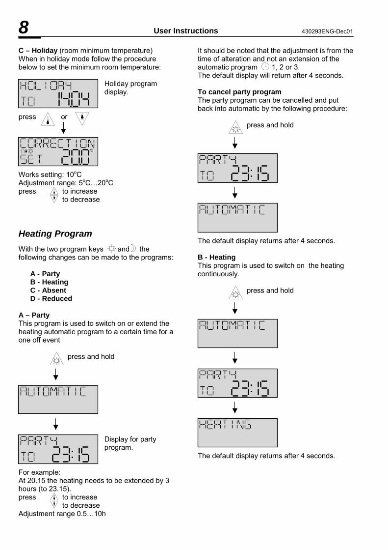
8 User Instructions 430293ENG-Dec01 C – Holiday (room minimum temperature) When in holiday mode follow the procedure below to set the minimum room temperature:
Holiday program display.
press or Works setting: 10oC Adjustment range: 5oC�20oC press to increase to decrease Heating Program With the two program keys and the following changes can be made to the programs:
A - Party B - Heating C - Absent D - Reduced
A – Party This program is used to switch on or extend the heating automatic program to a certain time for a one off event press and hold
Display for party program.
For example: At 20.15 the heating needs to be extended by 3 hours (to 23.15). press to increase to decrease Adjustment range 0.5�10h
It should be noted that the adjustment is from the time of alteration and not an extension of the automatic program 1, 2 or 3. The default display will return after 4 seconds. To cancel party program The party program can be cancelled and put back into automatic by the following procedure: press and hold
The default display returns after 4 seconds. B - Heating This program is used to switch on the heating continuously. press and hold
The default display returns after 4 seconds.

430293ENG-Dec01 User Instructions 9 To cancel heating program The continuous heating program can be cancelled using the following procedure: press and hold
The default display will return after 4 seconds. C – Absent This program is used to switch to reduced or extend the reduced automatic program to a certain time for a one off event press and hold
Display for absent program.
For example: At 13.00 the heating is switched to reduced for the next 6 hours (to 19.00). press to increase to decrease Adjustment range 0.5�10h It should be noted that the adjustment is from the time of alteration and not an extension of the automatic program 1, 2 or 3. The default display will return after 4 seconds. To cancel absent program The absent program can be cancelled and put back into automatic by the following procedure: press and hold
The default display will return after 4 seconds. D - Reduced This program is used to switch to reduced continuously. press and hold
The default display returns after 4 seconds. To cancel reduced program The continuous reduced program can be cancelled using the following procedure: press and hold
The default display will return after 4 seconds.

10 User Instructions 430293ENG-Dec01 Calorifier Charging With this program it is possible to switch the calorifier on for a fixed three hour period. press simultaneously
The default display will return after 4 seconds. To Cancel program: press simultaneously
The default display will return after 4 seconds. Attention: The calorifier will be heated up to its
maximum permissible temperature.

430293ENG-Dec01 Advanced User Instructions 11
Language The room station is programmed in three languages English, German and French. To change the language press or key for 5 seconds. Once the language appears the keys can be used to change languages. or Works setting: ENGLISH The previous display will return in a few seconds. 1 - Clock setting The following functions can be set:
- Time (minutes, hours) - Day - Month - Year
The clock can be set to automatically change over from summer to winter time by a parameter in the service level of the central unit. Changing clock settings The clock can be changed by using key and then the and keys to increase or decrease the values. - Time
Change with: to increase to decrease Setting Range:
00:00 � 23:59 - Date
Change with: to increase to decrease Setting Range:
1 � 31
- Month
Change with: to increase to decrease Setting Range:
1 � 12 - Year
Change with: to increase to decrease Setting Range:
1995 � 2030 - Return to default display If the key is not pressed the default display will return after 2 minutes. It is possible to return to the default display at any time using the information key. 2 - Time clock level In the time clock level the individual program times can be customized. Standard heating programs 1, 2 and 3 can be called up as desired and overwritten with different switch times and temperatures. Each standard program can thus be configured individually and stored under the same program number so that three different programs are available on demand. These can then simply be called up in the user operating level see page 6 for setting of the automatic program. Note: Programming of room temperatures is only
possible if the relevant parameter has been enabled in the service level by an engineer.
If this has not been done it is only possible to change the on / off times. In this case the room temperature will be the works setting of 20ºC or the corrected value which has been set in the user level. The standard programs are lost when overwritten by customized programs. These are cancelled after a reset and replaced by the standard programs and therefore have to be recreated if needed.

12 Advanced User Instructions 430293ENG-Dec01 Room temperature correction for PARTY and HEATING with variable temperature parameter enabled. For operating types:
- PARTY - HEATING
The room temperature is set to automatic works setting of 20ºC or the corrected value which has been set in the user level. The actual room temperature values for each of these two operating types can be set independently to the automatic program if the relevant parameter has been enabled in the service level by an engineer. The value is set separately when calling up the operating type PARTY or HEATING by using the and keys. These values remain stored for each further call of this operating type. Room temperature correction during automatic with variable temperature parameter enabled. During automatic operation the room temperature can be corrected using the and keys. The value can also be corrected for PARTY or HEATING operation by pressing the key and for REDUCED operation by pressing the key. Entering the time clock level Entering this level is achieved by simply pressing the key. Initially the heating cycle which the room station has been set to is shown. The three programs 1, 2 or 3 can be selected using the and keys. Press key
Boiler circuit Works setting: 2 Change with and keys
or (if present)
Mixer circuit 1 Works setting: 2 Change with and keys
or (if present)
Mixer circuit 2 Works setting: 2 Change with and keys
With the and keys all of the heating circuits together with the hot water circuit can be called up and are available for programming. Time Clock Programming It is possible to program up to three cycles periods for each desired weekday. Each of these cycles has an on / off as well as a temperature indication for this time span. The temperature can only be adjusted if the relevant parameter is enabled in the service level. The temperature indication refers to the heating cycle. The temperature between heating cycles is controlled according to the setting at the central unit. For the hot water programs the temperature indication refers to the hot water temperature. Calling up of heating cycles With a further pressing of the key the first heating cycle of the selected program shows complete with indication of weekday, cycle number, on time, off time and temperature. Each value is called up with the key in series
- On time - Off time - Temperature
The key can be used to step backwards. The current value which can be changed with the and keys is shown blinking. Switch times can be altered in 5 minute intervals and temperatures in 0.5K increments in the range of 5-30ºC. The next heating cycle can be called up by pressing the key and the process repeated. Note: The on/off times of not used heating cycles
should be set to 00:00 by simultaneously pressing the and keys. The 00:00 value does not refer to a clock time but only shows an undefined switch time.

430293ENG-Dec01 Advanced User Instructions 13 After programming the last heating cycle (Sunday � cycle 3) the first heating cycle (Monday � cycle 1) will follow. By pressing the key in quick succession the programmed cycles can be called up in series the values noted and corrected if necessary. Time clock level can be exited by pressing the key. Press to enter Cycle program Cycle 1 Monday
ON
Change with Next setting
OFF
Change with Next setting
TEMP (only when set in service level parameters)
Change with Next cycle Cycle 2 Monday
ON
Change with Next setting
OFF
Change with Next setting
TEMP (only when set in service level parameters)
Change with Next cycle Cycle 3 Monday
ON
Change with Next setting
OFF
Change with Next setting
TEMP (only when set in service level parameters)
Change with Next cycle Remaining days in week Program as Monday
Tuesday ON cycle 1
Sunday OFF cycle 3
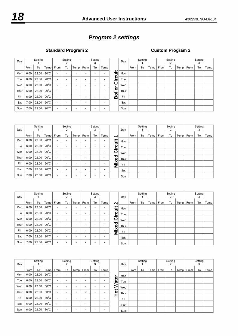
Time clock program The tables shown on pages 17-19 give an overview of the works programmed standard programs together with temperature settings which cannot be lost. When creating customized programs note the appropriate values in the tables.

14 Advanced User Instructions 430293ENG-Dec01 Canceling of individual heating cycles If necessary individually created cycles can be cancelled. After selecting the required cycle by pressing the key several times the cycle can be cancelled by pressing the and keys simultaneously. Enter the time program
or mixer circuit 1 or mixer circuit 2 or hot water
Press several times until the desired cycle appears
Press Simultaneously
Cycle cancelled
Block programming In order to simplify the programming of the time clocks it is possible to copy the time clock settings in various ways. A – Complete automatic programs It is possible to copy complete programs to other programs for example boiler circuit program 1 to mixed circuit 2 program 2. This can be achieved by using the key to enter the time clock and then the keys to select the program to use as the source. The key is used to select the target program to which it is to be copied. The key is used to complete the copy. The procedure is shown in further detail by the illustration on page 15. Note: It is not possible to copy heating circuit
programs to hot water programs or vice versa.
Restore standard program To restore a customized program to a works standard program select the program as described on page 12 (entering time clock level). Enter the time program
or mixer circuit 1 or mixer circuit 2 or hot water
Press Simultaneously
standard program restored
or mixer circuit 1 or mixer circuit 2 or hot water
Time clock level can be exited by pressing the key. The default display will then be restored.
B – Day to day or week Time programs can also be copied from day to the whole week or from day to day for example Tuesday to Wednesday. Day to week While in the time clock see page 13 the key followed by the key can be used to copy the current day to the whole week. The procedure is shown in further detail by the illustration on page 16. Day to day While in the time clock see page 13 the current day can be copied to another day by using the key two or more times to select the target day. The key is used to complete the copy of the current day to the target day. The procedure is shown in further detail by the illustration on page 16.
i

430293ENG-Dec01 Advanced User Instructions 15
Program 1
Program 2
Hot Water
Program 1
Program 2
Program 3
Mixed Circuit 2
Program 1
Program 2
Program 3
Mixed Circuit 1
Program 1
Program 2
Program 3
Boiler Circuit
Use or to change program no.
use to enter program to be copied to
Copy will appear
Press key to confirm copy
OK appears to confirm program copied
New source program for further copying
Program will blink
* * *
* only if present
Source program Source program Boiler circuit program 1 Target program mixer circuit 2 program 2 Program copied Target program = Source program
Copy Mixer 2 prog. 2 from boiler circuit prog. 1
Copy hot water prog. 3 from hot water prog. 2
Press to enter clock program
Program will blink
Heating circuit

16 Advanced User Instructions 430293ENG-Dec01 Room temperature corrections with individual temperature cycle programs (heating cycle only) When individual temperatures have been entered for each heating cycle, the desired room temperature can be altered via the correction keys or for one of the cycles. This change will then effect all other heating cycles as shown in the below example: Original cycle temperatures New cycle temperatures As the temperature was increased by 2K during cycle 2 the desired value has been increased by 2K in the other cycles.
Enter from heating cycle program Day copying
Day to copy (source day) Week Copying
Press
Target day to Copy to Press to copy Source day copied To target day Target day = Source for next copy
Press again to select target day
Copy again
Day copied to whole week Beginning of week now displayed
Press to copy
Cycle 2 20ºC + 2K = 22ºC
Cycle 1 18ºC + 2K = 20ºC
Cycle 3 22ºC + 2K = 24ºC Etc.
Cycle 2 20ºC
Cycle 1 18ºC
Cycle 3 22ºC
New Cycle 2 22ºC
Room temp + 2K

430293ENG-Dec01 Advanced User Instructions 17
Program 1 settings
Standard Program 1 Custom Program 1
Day Setting 1 Setting
2 Setting 3 Day Setting
1 Setting 2 Setting
3
From To Temp From To Temp From To Temp From To Temp From To Temp From To Temp
Mon 6.00 8.00 20oC 16.00 22.00 20oC - - - Mon
Tue 6.00 8.00 20oC 16.00 22.00 20oC - - - Tue
Wed 6.00 8.00 20oC 16.00 22.00 20oC - - - Wed
Thur 6.00 8.00 20oC 16.00 22.00 20oC - - - Thur
Fri 6.00 8.00 20oC 16.00 22.00 20oC - - - Fri
Sat 7.00 23.00 20oC - - - - - - Sat
Sun 7.00 23.00 20oC - - - - - -
Boi
ler C
ircui
t
Sun
Day Setting
1 Setting
2 Setting
3 Day Setting
1 Setting
2 Setting
3
From To Temp From To Temp From To Temp From To Temp From To Temp From To Temp
Mon 6.00 8.00 20oC 16.00 22.00 20oC - - - Mon
Tue 6.00 8.00 20oC 16.00 22.00 20oC - - - Tue
Wed 6.00 8.00 20oC 16.00 22.00 20oC - - - Wed
Thur 6.00 8.00 20oC 16.00 22.00 20oC - - - Thur
Fri 6.00 8.00 20oC 16.00 22.00 20oC - - - Fri
Sat 7.00 23.00 20oC - - - - - - Sat
Sun 7.00 23.00 20oC - - - - - -
Mix
ed C
ircui
t 1
Sun
Day Setting
1 Setting
2 Setting
3 Day Setting
1 Setting
2 Setting
3
From To Temp From To Temp From To Temp From To Temp From To Temp From To Temp
Mon 6.00 8.00 20oC 16.00 22.00 20oC - - - Mon
Tue 6.00 8.00 20oC 16.00 22.00 20oC - - - Tue
Wed 6.00 8.00 20oC 16.00 22.00 20oC - - - Wed
Thur 6.00 8.00 20oC 16.00 22.00 20oC - - - Thur
Fri 6.00 8.00 20oC 16.00 22.00 20oC - - - Fri
Sat 7.00 23.00 20oC - - - - - - Sat
Sun 7.00 23.00 20oC - - - - - -
Mix
ed C
ircui
t 2
Sun
Day Setting
1 Setting
2 Setting
3 Day Setting
1 Setting
2 Setting
3
From To Temp From To Temp From To Temp From To Temp From To Temp From To Temp
Mon 6.00 8.00 60oC 16.00 22.00 60oC - - - Mon
Tue 6.00 8.00 60oC 16.00 22.00 60oC - - - Tue
Wed 6.00 8.00 60oC 16.00 22.00 60oC - - - Wed
Thur 6.00 8.00 60oC 16.00 22.00 60oC - - - Thur
Fri 6.00 8.00 60oC 16.00 22.00 60oC - - - Fri
Sat 6.00 22.00 60oC - - - - - - Sat
Sun 6.00 22.00 60oC - - - - - -
Hot
Wat
er
Sun
18 Advanced User Instructions 430293ENG-Dec01
Program 2 settings
Standard Program 2 Custom Program 2
Day Setting 1 Setting
2 Setting 3 Day Setting
1 Setting 2 Setting
3
From To Temp From To Temp From To Temp From To Temp From To Temp From To Temp
Mon 6.00 22.00 20oC - - - - - - Mon
Tue 6.00 22.00 20oC - - - - - - Tue
Wed 6.00 22.00 20oC - - - - - - Wed
Thur 6.00 22.00 20oC - - - - - - Thur
Fri 6.00 22.00 20oC - - - - - - Fri
Sat 7.00 22.00 20oC - - - - - - Sat
Sun 7.00 22.00 20oC - - - - - -
Boi
ler C
ircui
t Sun
Day Setting
1 Setting
2 Setting
3 Day Setting
1 Setting
2 Setting
3
From To Temp From To Temp From To Temp From To Temp From To Temp From To TempMon 6.00 22.00 20oC - - - - - - Mon Tue 6.00 22.00 20oC - - - - - - Tue Wed 6.00 22.00 20oC - - - - - - Wed Thur 6.00 22.00 20oC - - - - - - Thur Fri 6.00 22.00 20oC - - - - - - Fri Sat 7.00 22.00 20oC - - - - - - Sat Sun 7.00 22.00 20oC - - - - - -
Mix
ed C
ircui
t 1
Sun
Day Setting
1 Setting
2 Setting
3 Day Setting
1 Setting
2 Setting
3
From To Temp From To Temp From To Temp From To Temp From To Temp From To TempMon 6.00 22.00 20oC - - - - - - Mon Tue 6.00 22.00 20oC - - - - - - Tue Wed 6.00 22.00 20oC - - - - - - Wed Thur 6.00 22.00 20oC - - - - - - Thur Fri 6.00 22.00 20oC - - - - - - Fri Sat 7.00 22.00 20oC - - - - - - Sat Sun 7.00 22.00 20oC - - - - - -
Mix
ed C
ircui
t 2
Sun
Day Setting
1 Setting
2 Setting
3 Day Setting
1 Setting
2 Setting
3
From To Temp From To Temp From To Temp From To Temp From To Temp From To TempMon 6.00 22.00 60oC - - - - - - Mon Tue 6.00 22.00 60oC - - - - - - Tue Wed 6.00 22.00 60oC - - - - - - Wed Thur 6.00 22.00 60oC - - - - - - Thur Fri 6.00 22.00 60oC - - - - - - Fri Sat 6.00 22.00 60oC - - - - - - Sat Sun 6.00 22.00 60oC - - - - - -
Hot
Wat
er
Sun

430293ENG-Dec01 Advanced User Instructions 19
Program 3 settings
Standard Program 3 Custom Program 3
Day Setting 1 Setting
2 Setting 3 Day Setting
1 Setting 2 Setting
3
From To Temp From To Temp From To Temp From To Temp From To Temp From To Temp
Mon 6.00 23.00 20oC - - - - - - Mon
Tue 6.00 23.00 20oC - - - - - - Tue
Wed 6.00 23.00 20oC - - - - - - Wed
Thur 6.00 23.00 20oC - - - - - - Thur
Fri 6.00 23.00 20oC - - - - - - Fri
Sat 7.00 23.00 20oC - - - - - - Sat
Sun 7.00 22.00 20oC - - - - - -
Boi
ler C
ircui
t
Sun
Day Setting
1 Setting
2 Setting
3 Day Setting
1 Setting
2 Setting
3
From To Temp From To Temp From To Temp From To Temp From To Temp From To TempMon 6.00 23.00 20oC - - - - - - Mon Tue 6.00 23.00 20oC - - - - - - Tue Wed 6.00 23.00 20oC - - - - - - Wed Thur 6.00 23.00 20oC - - - - - - Thur Fri 6.00 23.00 20oC - - - - - - Fri Sat 7.00 23.00 20oC - - - - - - Sat Sun 7.00 22.00 20oC - - - - - -
Mix
ed C
ircui
t 1
Sun
Day Setting
1 Setting
2 Setting
3 Day Setting
1 Setting
2 Setting
3
From To Temp From To Temp From To Temp From To Temp From To Temp From To TempMon 6.00 23.00 20oC - - - - - - Mon Tue 6.00 23.00 20oC - - - - - - Tue Wed 6.00 23.00 20oC - - - - - - Wed Thur 6.00 23.00 20oC - - - - - - Thur Fri 6.00 23.00 20oC - - - - - - Fri Sat 7.00 23.00 20oC - - - - - - Sat Sun 7.00 22.00 20oC - - - - - -
Mix
ed C
ircui
t 2
Sun
Day Setting
1 Setting
2 Setting
3 Day Setting
1 Setting
2 Setting
3
From To Temp From To Temp From To Temp From To Temp From To Temp From To TempMon 6.00 23.00 60oC - - - - - - Mon Tue 6.00 23.00 60oC - - - - - - Tue Wed 6.00 23.00 60oC - - - - - - Wed Thur 6.00 23.00 60oC - - - - - - Thur Fri 6.00 23.00 60oC - - - - - - Fri Sat 6.00 23.00 60oC - - - - - - Sat Sun 6.00 22.00 60oC - - - - - -
Hot
Wat
er
Sun

20 Advanced User Instructions 430293ENG-Dec01 3 - Room Level At this level, the parameters relevant to the heating requirements of the building and its characteristics can be displayed and changed.
- Hot water temperature - Burner hours run - Burner starts - Holiday program - Clock programs - Heating curves - Room temperature correction - Reset function
Entering the Room Level Room level can be entered by using the key. Changes can be made using the , and keys. To exit the room level press the key at any time. Press and hold for 3 secs
Hot water temperature
Works setting: TopTronic 1B and 133B → 55ºC Other TopTronics → 60ºC Adjustment range 10ºC � Hot water maximum temperature press to increase to decrease The maximum temperature is set in the technical parameter level.
Burner hours run on 1ST stage
Works setting: 000000.00h Range: 0 � 99999999
Number of burner starts on 1st stage
Works setting: 00000000 Range: 0 � 99999999
Burner hours run on 2nd stage
Works setting: 000000.00h Range: 0 � 99999999
Number of burner starts on 2nd stage
Works setting: 00000000 Range: 0 � 99999999
Holiday program start
Adjust with to increase and to decrease Change between day and month with and This function is used to switch the heating to frost protection only while the building is unoccupied for example a holiday. The default display will be today�s date.
Holiday program finish
Adjust with to increase and to decrease Change between day and month with and This function is used to switch the heating back on when the building becomes occupied. Example of holiday program
The heating will be switched to frost protection only on the 29.3 at 24.00 hrs
i

430293ENG-Dec01 Advanced User Instructions 21
The heating will remain off from 30.3 00.00 hrs to 14.4 00.00 hrs. This will be
the default display until the heating is started again on 14.4.
Hot water clock program
Works setting: Program 2 Options: Program 1 Program 2 Program 3 Change with or With this parameter it is possible to change between the three clock programs for hot water, see pages 17 to 19 for settings.
Boiler circuit clock program
Works setting: Program 2 Options: Program 1 Program 2 Program 3 Change with or With this parameter it is possible to change between the three clock programs for the boiler circuit, see pages 17 to 19 for settings.
Mixed circuit 1 clock program
Works setting: Program 2 Options: Program 1 Program 2 Program 3 Change with or With this parameter it is possible to change between the three clock programs for mixed circuit 1, see pages 17 to 19 for settings.
Mixed circuit 2 clock program Works setting: Program 2
Options: Program 1 Program 2 Program 3 Change with or With this parameter it is possible to change between the three clock programs for mixed circuit 2, see pages 17 to 19 for settings.
Heating curve for boiler circuit
Works setting: 1.4 Range: 0.20 � 3.5 Change with or With this parameter it is possible to change the slope of the heating curve for the boiler circuit (see graph).
Heating curve for mixed circuit 1
Works setting: 1.4 Range: 0.20 � 3.5 Change with or With this parameter it is possible to change the slope of the heating curve for mixed circuit 1 (see graph).
Heating curve for mixed circuit 2
Blinks if auto adaption is set in service level parameters (do not change)
Blinks if auto adaption is set in service level parameters (do not change)
Blinks if auto adaption is set in service level parameters (do not change)

22 Advanced User Instructions 430293ENG-Dec01 Works setting: 1.4 Range: 0.20 � 3.5 Change with or With this parameter it is possible to change the slope of the heating curve for the boiler circuit (see graph). The heating curve gives the (boiler and / or mixed circuit) flow temperature / outdoor temperature ratio. The curve should only be reset with minimum changes spread out over a certain period of time to enable the regulator to react (by nature a heating installation is very slow to react). Corrections of 0.1 increments every 1 or 2 days is recommended. Note: The room station should be placed in the
room that most accurately represents the temperature of the building. Thermostatic radiator valves when fitted properly should only serve to deregulate foreign heat sources and therefore should be fully open. During the regulation phase all foreign heat source should be switch off and ventilation should be kept to a minimum so as not to disturb the regulation process.
When the heating curve is correctly set the room temperature should remain constant regardless of outside temperature. If automatic adaption is set in the service level the value will blink and is constantly corrected. In this case it must not be manually altered. Recommended values: Floor heating: 0.3 �.. 1.0 Radiator heating: 1.2 �.. 2.0 Convection heating: 1.5 �.. 2.0 Heating curve graph
Room temperature compensation
1 2 Works setting: 0.0K Range: -2.5K � +2.5K Change with or 1 � Room temperature 2 � Correction With this parameter it is possible to calibration the room temperature by ± 2.5K.
Reset function
With this function it is possible to reset all the room level parameters back to their factory settings with the exception of burner hours run and burner starts. To reset room level parameters hold and Simultaneously until the following display appears
Parameters reset
Default display
Max temp
Min temp
Outside temperature ºC
Boiler Flow Temp ºC

430293ENG-Dec01 Room Level Parameters 23
Parameter Function With TopTronic Range Factory Setting
Current Setting
1. Burner hours run 1B, 133B 2B, 23B, 233B 223B, 2233B 203B
000000.00 � 999999.59
000000.00
2. Burner starts 1B, 133B 2B, 23B, 233B 223B, 2233B 203B
00000000 � 99999999
00000000
3. Burner hours run on 2nd stage
223B, 2233B 000000.00 � 999999.59
000000.00
4. Burner starts on 2nd stage 223B, 2233B 00000000 � 99999999
00000000
5. Holiday program start 1B, 133B 2B, 23B, 233B 223B, 2233B 203B 3
01/01 � 31/12 Not set
6. Holiday program finish 1B, 133B 2B, 23B, 233B 223B, 2233B 203B 3
01/01 � 31/12 Not set
7. Clock program for HWS 1B, 133B 2B, 23B, 233B 223B, 2233B 203B
1 � 2 � 3
2
8. Clock program for boiler circuit
1B, 133B 2B, 23B, 233B 223B, 2233B 203B
1 � 2 � 3
2
9. Clock program for mixed circuit 1
1B, 133B 2B, 23B, 233B 223B, 2233B 203B
1 � 2 � 3
2
10. Clock program for mixed circuit 2
1B, 133B 2B, 23B, 233B 223B, 2233B 203B
1 � 2 � 3
2
1B, 133B 55oC 11. HWS temp (only with greater access program) 2B, 23B, 233B
223B, 2233B 203B
10oC
60oC
12. Heating curve � boiler circuit 1B, 133B 2B, 23B, 233B 223B, 2233B 203B
0.20�3.50 1.4
13. Heating curve � mixed circuit 1
1B, 133B 2B, 23B, 233B 223B, 2233B 203B
0.20�3.50 1.4
14. Heating circuit � mixed circuit 2
133B 233B 2233B
0.20�3.50 1.4
15. Room temperature compensation
1B, 133B 2B, 23B, 233B 223B, 2233B 203B 3
16. Reset to factory settings

24 Advanced Parameter Table 430293ENG-Dec01
Factory settings No. Parameter Function Adj. Range 133B 1B 2B 23B 233B 2233B 223B 3 203B Current Setting
1 Frost Protection -20°C...10°C 0 0 0 0 0 0 0 0 0 2 Summer switch-off Aus, 10°C...30°C 17°C 17°C 17°C 17°C 17°C 17°C 17°C 17°C 17°C 3 Minimum outdoor temperature -20...0 -10 -10 -10 -10 -10 -10 -10 -10 -10 4 Maximum flue gas temperature 70°C...250°C 250°C 250°C 250°C 250°C 250°C 250°C 250°C 5 Maximum boiler temperature 10°C...95°C (90°C Gas) 80°C 80°C 85°C 85°C 85°C 85°C 85°C 85°C 6 Boiler return temperature 0...70°C 0 38°C 38°C 38°C 38°C 38°C 7 Blr circ Temp rise (Above mix circ) 0(-5K 133B,3)...20K) 0K 8 K 8 K 12 K 12 K 8K 8 K 8 Pump overrun 0...15 min 5 min 5 min 5 min 5 min 5 min 5 min 5 min 5 min 5 min 9 Boiler minimum temperature 10°C(0°C 203B)...95°C 48°C 48°C 48°C 48°C 48°C 0 °C
Type of hot water priority 1,2,3 3 2 2 3 3 3 3 3 1: None X X X X X X X X 2: Priority X X X X X X X X
10
3: Priority with reservation X X X X X X 11 Maximum hot water temperature 40°C...80°C 60°C 60°C 60°C 60°C 60°C 60°C 60°C 60°C
Type of calorifier sensor 1,2 2 2 2 2 2 2 2 2 1: Thermostat X X X X X X X X 12
2: Sensor X X X X X X X X 13 Protection against Legionella 0...8 8 8 0 0 0 0 0 0 14 Night water load 0.1...1.0 0.3 0.3 15 Dom H/water installation load temp 0...50K 20 K 20 K 25 K 25 K 25 K 25 K 25 K 25 K 20 Influence room temp on blr circ KK 0...2.5 0.5 0.5 1.0 1.0 1.0 1.0 1.0 1.0
Blr circ automatic adaption KK 0,1 0 1 1 0 0 0 0 0 0: Off X X X X X X X X 21
1: On X X X X X X X X Boiler circuit user index KK 1,2,3 2 2 2 2 2 2 2 2 1: 1.00 X X X X X X X X 2: 1.31 X X X X X X X X
22
3: 2.00 X X X X X X X X 23 Blr circ derivative action time KK 0...6h 2h 2h 1h 1h 1h 1h 1h 1h
Blr circ ext sensor detection KK 0,1,2 0 0 0 0 0 0 0 0 0: Average value X X X X X X X X 1: External sensor 1 X X X X X X X X
24
2: External sensor 2 X X X X X X X X 27 Boiler circ constant temp reg KK 0..95 (90°C Gas) °C 0 0 0 0 0 0 30 Influence room temp blr circ MK1 0...2.5 0.5 1.0 1.0 1.0 1.0 1.0 1.0
Mixed circ 1 auto adaption MK1 0,1 1 1 1 1 1 1 1 0: Off X X X X X X X 31
1: On X X X X X X X 32 Mixed circuit minimum temp MK1 0...95°C (90°C Gas) 0 0 0 0 0 0 0 33 Mixed circuit maximum temp MK1 10°C...95°C (90°C Gas) 80°C 80°C 80°C 80°C 80°C 80°C 80°C
Mixed circuit 1 user index MK1 1,2,3 2 2 2 2 2 2 2 1: 1.00 X X X X X X X 2: 1.31 X X X X X X X
34
3: 2.00 X X X X X X X 35 Mix circ1 derivative action time MK1 0...6h 2h 1h 1h 1h 1h 1h 1h
Mix circ 1 ext sens. detection MK1 0,1,2 0 0 0 0 0 0 0 0: Average value X X X X X X X 1: External sensor 1 X X X X X X X
36
2: External sensor 2 X X X X X X X 40 Influence room temp mix circ 2MK2 0...2.5 0.5 1.0 1.0
X = Possible settings

430293ENG-Dec01 Advanced Parameter Table 25
Factory settings No. Parameter Function Adj. Range 133B 1B 2B 23B 233B 2233B 223B 3 203B Current Setting
Mixed circ 2 auto adaption 2MK2 0,1 1 1 1 0: Off X X X 41
1: On X X X 42 Mixed circ 2 minimum temp MK2 0...95°C (90°C Gas) 0 0 0 43 Mixed circ 2 maximum temp MK2 10°C...95°C (90°C Gas) 80°C 80°C 80°C
Mixed circuit 2 user index MK2 1,2,3 2 2 2 1: 1.00 X X X 2: 1.31 X X X
44
3: 2.00 X X X 45 Mix circ2 derivative actiontimeMK2 0...6h 2h 1h 1h
Mix circ2 ext sensor detect MK2 0,1,2 0 0 0 0: Average value X X X 1: External sensor 1 X X X
46
2: External sensor 2 X X X 47 Mix circ 2 const. reg operat'n MK2 0...95°C (90°C Gas) 0 0 0 48 Mixed circ2 fixed point regulation 0...95°C (90°C Gas) 0 0 0
Summer/winter switchover 0,1 1 1 1 1 1 1 1 1 1 0: Off X X X X X X X X X 60
1: On X X X X X X X X X Control output programming X3-3 1 ... 7 4 1 1 4 4 5 5 5 1: Boiler circuit pump X X X X X X X X 2: Casc. Boil. Interm. Valve X X X X X X X X 3: Fault signal output X X X X X X 4: Boiler circuit lock X X X X X X 5: Primary pump X X X X X X 6: Low return temp protection pump X X X X X
61
7: Switch-on with external sensor X Control output programming X4-10 1,2,3,4 1 4 4 3 3 1: Heat pump/solar/wood X X X X X 2: Fault signal output X X X X X 3: Boiler circ. Clock X X X X X
62
4: Electrical battery X X X X Control output programming X4-11 1,2,3,4 1 1 1 1 1 1 1: Fault signal output X X X X X X 2: Pump minimum speed X X X X X X 3: Clock channel X X X X X
63
4: Heat pump/solar/wood X X X X X X 64 Bus address 1...5 1 1 1 1 1 1 1 1 1
Boiler cascade 0,1 0 0 0 0 0 0 0: Single boiler X X X X X X 65
1: Cascade X X X X X X Level lock up 0,1,2,3 0 0 0 0 0 0 0 0 0 0: No lock up X X X X X X X X X 1: Room level lock up X X X X X X X X X 2: Clock lock up X X X X X X X X X
66
3: Room level and clock lock up X X X X X X X X X Reduced operation 0,1 1 1 1 1 1 1 1 1 1 0: ECO - (Switch-off) X X X X X X X X X 67
1: Abs (Reduction) X X X X X X X X X 68 Minimum Room Temperature 5°C...20°C 5 °C 5 °C 5 °C 5 °C 5 °C 5 °C 5 °C 5 °C 5 °C
X = Possible settings

26 Advanced Parameter Table 430293ENG-Dec01
Factory settings No. Parameter Function Adj. Range 133B 1B 2B 23B 233B 2233B 223B 3 203B Current Setting
Pump seizure protection 0,1 1 1 1 1 1 1 1 1 1 0: Off X X X X X X X X X 69
1: On X X X X X X X X X C/return protect during Blr turnon 0,1 1 1 1 1 1 1 0: Off X X X X X X 70
1: On X X X X X X 71 Extended burner operation time 0...20 min 10 min 10 min 10 min 10 min 10 min 20 min 72 1st stage differential 2...30K 6 K 6 K 6 K 6 K 6 K 10 K 73 2nd stage differential 2...30K 12 K 12 K 74 2nd stage delay 0...60min 10 min 10 min 10 min 75 Lock 2stage with Outdoor temp Aus, -15°C...30°C 10°C 10°C 10°C
Hot water power select for 2stage 1...3 3 3 3 1: With outdoor temp and delay X X X 2: With outdoor temp without delay X X X
76
3: Without limitations X X X Control input programming X1-33 0,1,2 0 0 2 2 2 0: Dom water heat (auto/Blr/Elec) X X X X 1: Priority inversion X X X
80
2: Burner operation X X X X X Alarm logic signals 0,1 1 1 1 1 1 1 1 1 1 0: Off X X X X X X X X X 81
1: On X X X X X X X X X 82 RESET RESET X X X X X X X X X 83 Relay Test alle Relais / all relays X X X X X X X X X
X = Possible settings

430293ENG-Dec01 Installation / Technical Data 27
Installation
Positioning – without room sensor If there is no room sensor or the room sensor has not been activated the unit can be placed as desired.
Positioning – with room sensor When used with the unit sensor activated the unit must be placed at a height of approximately 1.20 to 1.50 m in a place representing the temperature of all rooms. It is advisable to choose an internal wall in the coolest room which is used in the day.
The unit may not be positioned: • In direct sunlight (take note of the position of the sun in winter) • Near any equipment which produces heat like televisions, wall lights, radiators etc. • On walls where hot water pipes or chimneys run. • On outside walls which are not insulated. • In corners, recesses, shelves or behind curtains (insufficient air circulation). • Near doors which lead to unheated rooms. • In rooms which are regulated with thermostatic valves.
Mounting Open the cover and loosen the screw inside. Lift the unit off the back plate. Secure the back plate with the screws provided. The data bus cable must be threaded through the lower part of the back plate. With a data bus cable of over 50m cable of types JY-(ST) 2x2x0.6 or LI YC T (TP) 2x2x0.75 must be used. The screening must be connected to the earth terminal of the boiler. Note: on new installations use a box behind the room station.
Electrical Connection Before connecting / wiring the power at the boiler must be off. The 4 core bus cable is connected to the 4 pole terminal on the back plate. After the wiring is complete the room station is slotted in from above and screwed to the back plate. Note: by incorrect wiring the remains in VERSION indication for approximately 1 minute and then goes to fault indication. Technical Data
Wiring: 4 pole screwed terminals on back plate for 1mm2 max wire cross section.
Bus Interface: RS485
Power supply: From central unit
Color: White RAL 9016
Fixing distance: 60mm (2 hole fixing) Wall Fixing: 2 x 3mm dia x 18 long
Weight: 170g
Operating Temperature: -10oC�.+50oC
Storage Temperature: -25oC�.+60oC
Indication: Alpha numeric text indication as well as symbols