user instructions - flowservepreview.flowserve.com/files/files/literature/productliterature/... ·...
TRANSCRIPT

Experience In Motion
USER INSTRUCTIONS
InstallationOperation
Maintenance
MX/QX FOUNdaTION Fieldbus Field UnitFCD LMENIM2330-01 – 08/11

MX/QX FOUNdaTION Fieldbus Field Unit FCd LMENIM2330-01 – 08/11
2
Contents1 Introduction 4
1.1 Purpose 41.2 How to Use this Manual 41.3 User Safety 51.4 User Knowledge 51.5 MX/QX FF System Capabilities and Features 6
1.5.1 General Network Specification 82 SystemComponentsandInstallation 9
2.1 Introduction 92.2 Hardware 9
2.2.1 MX/QX Electric Actuators 102.2.2 MX/QX FF Interface Board 112.2.3 Network Host 12
2.2.3.1 LAS Tasks 122.2.4 Network Cable 13
2.3 Other Network Components 142.4 Cable Shielding and Grounding 152.5 Fieldbus Power Supply 152.6 Site and Network Cable Preparation 16
2.6.1 Site Preparation 162.6.2 Network Cable Preparation 17
2.6.2.1 Network Cable Connection to the MX/QX FF Unit 172.6.2.2 Network Cable Connections to Other Network Components 212.6.2.3 Cable Length and Number of Devices Requirements 212.6.2.4 Network Cable Connection to the Host System (DCS) 22
2.6.3 MX/QX FF Device Installation 222.6.4 MX/QX FF Device Setup 22
2.6.4.1 Proportional Band 242.6.4.2 Deadband 24
2.6.5 Valve Data 242.7 MX/QX FF Device Description and Capabilities Files Installation 24
2.7.1 MX/QX FF Device Description 242.8 Installation Verification 25
2.8.1 Network Cabling Installation Verification 252.8.2 MX/QX FF Device Installation Verification 25
2.9 Configuration Confirmation 252.9.1 Checking Connections 252.9.2 View Settings 262.9.3 Checking the Normal Display 26
3 Software 273.1 Fieldbus Protocol 273.2 Fieldbus Function Blocks 273.3 Analog Input Function Block 283.4 Analog Output Function Block 303.5 Discrete Input Function Block 313.6 Discrete Output (DO) Function Block 333.7 Proportional Integral Derivative (PID) Function Block 343.8 Transducer Block 383.9 Device Description and Capabilities Files, and Device Type Manager (DTM) 383.10 Device Type Manager (DTM) 39
3
MX/QX FOUNdaTION Fieldbus Field Unit FCd LMENIM2330-01 – 08/11
flowserve.com
Contents4 AssociatedDocuments 405 HowtoOrderParts 41A AppendixA–WiringDiagrams 42B Appendix–FeatureDefinitions 45C Appendix–FieldbusParameterDescriptions 70Glossary 80
FiguresFigure 1.1 – Typical FOUNDATION Fieldbus System with a DCS Host 7Figure 2.1 – MX-05 Actuator 9Figure 2.2 – QX-05 Actuator 10Figure 2.3 – MX/QX Interface Board 12Figure 2.4 – Cable Topologies 14Figure 2.5 – Use of Shielded Cable 15Figure 2.6 – Fieldbus Power Supply with External Termination 16Figure 2.7 – Fieldbus Power Supply with MX/QX FF Termination 16Figure 2.8 – Network Cable Connections to Terminal Blocks 17Figure 2.9 – Removing Outer Plastic Jacket 18Figure 2.10 – Seperating Cable Parts 18Figure 2.11 – Stripping Conductors 19Figure 2.12 – Applying Heat Shrink Tubing 19Figure 2.13 – Ring tongue connectors 19Figure 2.14 – Connecting Network Cable to MX/QX Terminal Block 20Figure 2.15 – Network with Spurs 21Figure 2.16 – MX FF/QX Setup Sequence 23Figure 2.17 – Normal Display 26Figure 3.1 – Fieldbus Function Blocks 28Figure 3.2 – Analog Input Block 29Figure 3.3 – Analog Output Block 30Figure 3.4 – Discrete Input Function Block 32Figure 3.5 – Discrete Output Function Block 33Figure 3.6 - PID Function Block 35Figure A.1 (1 of 3) – Typical MX/QX FF_H1 Wiring Diagram 42Figure A.2 (2 of 3) – Typical MX/QX FF_H1 Wiring Diagram (continued) 43Figure A.3 (3 of 3) – Typical MX/QX FF_H1 Wiring Diagrams Notes 44
TablesTable 2.1 – MX Actuator Components 9Table 2.2 – QX Actuator Components 10Table 2.3 – Recommended Cable Types 13Table 2.4 – Loop Topology Connection 20Table 2.5 – Recommended Maximum Spur Length, m (ft) 22Table 3.1 – Description of the Function Blocks 28Table 3.2 – Summary of Device Descriptions and Capabilities Files 39
MX/QX FOUNdaTION Fieldbus Field Unit FCd LMENIM2330-01 – 08/11
4
1Introduction
1.1 Purpose This manual explains how to install and operate the MX/QX FOUNDATION™ fieldbus field unit (MX/QX FF). Actuators containing the FF field unit may be connected by a single twisted-pair cable to form a FOUNDATION fieldbus communication system network. The FOUNDATION fieldbus communication system is a digital, serial, two-way bus system running at 31.25 kbits/s. This system allows a host system such as a distributed control system (DCS) to control and monitor the actuators, including the acquisition of status and alarm data from each MX/QX.
1.2 How to Use this Manual Each section provides the MX/QX FF user with information on installing and operating the MX/QX FF field unit.
Section1.IntroductionDetails user safety and knowledge requirements, system capabilities, and features.
Section2.SystemComponentsFocuses on the description of the FOUNDATION fieldbus system hardware and software components.
Section3.InstallationandConfigurationProvides details for installing and configuring a field unit.
Section4.AssociatedDocumentsProvides a list of documents on related subjects for additional MX/QX and FOUNDATION fieldbus system information.
Section5.HowtoOrderParts
AppendixA–WiringDiagramDetail wiring connections to the MX/QX field unit.
AppendixB–FeatureDefinitionsLimitorque actuator Transducer Block I/O channels and parameters.
AppendixC–FieldbusParameterDescriptionsFOUNDATION Fieldbus Function Block parameters and descriptions.
Glossary
Index

5
MX/QX FOUNdaTION Fieldbus Field Unit FCd LMENIM2330-01 – 08/11
flowserve.com
1.3 User Safety Safety notices in this manual detail precautions the user must take to reduce the risk of personal injury and damage to the equipment. The user must read and be familiar with these instructions before attempting installation, operation, or maintenance. Failure to observe these precautions could result in serious bodily injury, damage to the equipment, warranty void, or operational difficulty. User must follow local and state safety regulations.
Safety notices are presented in this manual in three forms:
c WARNING: Refers to personal safety. Alerts the user to potential danger. Failure to follow warning notices could result in personal injury or death.
a CAUTION: Directs the user’s attention to general precautions that, if not followed, could result in personal injury and/or equipment damage.
NOTE: Highlights information critical to the user’s understanding of the actuator’s installation and operation.
1.4 User Knowledge It is recommended that the user read this manual in its entirety before the MX/QX FF equipped actuator is installed and operated.
The user needs to have a fundamental knowledge of electronics and microprocessor concepts. An understanding of valve actuators and digital control systems is beneficial to the field unit user. Refer to the Glossary for terms used throughout this manual.
The following web sites have documents on Foundation Fieldbus and electric actuators: www.fieldbus.org and www.flowserve.com
For fieldbus technology and cabling information, refer to the following documents:
• FOUNDATION Fieldbus Wiring and Installation 31.25 kbits/s, Voltage Mode, Wire Medium AG-140
• FOUNDATION Fieldbus Technical Overview, FD-043
• Relcom Inc. Fieldbus Wiring Design and Installation Guide
• ANSI/ISA-S50.02, Part 2-1992, Fieldbus Standard for Use in Industrial Control Systems Part 2: Physical Layer Specification and Service Definition
• FOUNDATION Fieldbus FF-890 and FF-891, FOUNDATION Specification, Function Block Application Process, Part 1 and 2.
Reference can also be made to the following book:
• Fieldbuses for Process Control: Engineering, Operation, and Maintenance. ISBN 1-55617-760-7.

MX/QX FOUNdaTION Fieldbus Field Unit FCd LMENIM2330-01 – 08/11
6
1.5 MX/QX FF System Capabilities and Features Limitorque’s FOUNDATION fieldbus field unit conforms to the open fieldbus standard IEC 61158. It is suitable for use on the Fieldbus H1 highway and uses a twisted-pair cable for connection to the highway. The communication system theoretically supports up to 240 actuators with the use of repeaters.
The MX/QX FF field unit fits in the actuator in the sealed electrical housing. Adjustments to the MX/QX FF settings may be made over the FOUNDATION fieldbus data highway using a network configuration tool.
The MX/QX FF unit may command its actuator and others to:
• Open
• Stop
• Close
• Move to a set position
• Perform an emergency shutdown operation
• Read and control relays
• Perform partial stroke test
• Monitor analog inputs and position
• Monitor modes and alarms
Commands to the unit come over the network from the host system, which may be:
• Personal Computer (PC)
• Distributed Control System (DCS)
• Programmable Logic Controller (PLC)
• Field Device Tool (FDT) w/ Device Type Manager (DTM)
• Some other microprocessor-based device
Commands may also be generated in another network actuator or device and transmitted over fieldbus using peer-to-peer, consumer/producer communication.
The MX/QX FF also has the capacity of being a Link Active Scheduler (LAS) on a FOUNDATION Fieldbus network. It can be configured either for Basic or LAS mode. In BASIC mode, the MX/QX will display COMM LOSS if power is removed from the FF field unit. In LAS mode, the MX/QX will display HARDWARE FAILURE if power is removed from the FF field unit.
A fieldbus device is an intelligent device within the actuator that can send multiple variables to the control system over a high-resolution and distortion-free digital communication network. The device provides control and self-test capabilties, which allows abnormal conditions to be easily and immediately identified before an unplanned shutdown.
Additional features and capabilities are:
• The system reduces the cost of wiring and installation – existing wiring and multi-drop connections can be used
• The devices are interoperable – devices from different suppliers can communicate with one another on the same network.
A typical MX/QX FF system is shown in Figure 1.1.

7
MX/QX FOUNdaTION Fieldbus Field Unit FCd LMENIM2330-01 – 08/11
flowserve.com
Figure 1.1 – Typical FOUNDATION Fieldbus System with a DCS Host
Power for the fieldbus devices and cable shield grounding are discussed in Sections 2.4 and 2.5.
Fieldbus Network, wire pair
MX/QX FF
Actuator
MX/QX FF
Actuator
MX/QX FF
Actuator
MX/QX FF
Actuator
Fieldbus Interface
Control Highway
Distributed Control System (Host)
T Terminator
T
Terminator Wire pair with shield

MX/QX FOUNdaTION Fieldbus Field Unit FCd LMENIM2330-01 – 08/11
8
1.5.1 General Network Specification SystemSpecifications:• Communicates using the FOUNDATION fieldbus protocol
• Employs high-speed communication
• Complies with the IEC61158 fieldbus standard.
NetworkSpecificationSeveral topologies are available, point-to-point, bus with spurs, daisy chain, tree, or a combination of these. Network features include:
• Link Active Scheduler controls the system
• High-speed communications up to 31.25 kbits/s
• Peer-to Peer communication.
MX/QXFFFieldUnitSpecificationThe field unit mounts in the actuator and is software controlled in order to allow functionality of:
• Input and Output Function Blocks
• Proportional Integral Derivative (PID) Function Block
• Device descriptions
• Network communication
• Parameter configuration by user.
LinkActiveSchedulerSpecificationFieldbus segments have one, and only one, active Link Active Scheduler (LAS) at a given time. The LAS acts as the bus arbiter, and does the following:
• Recognizes and adds new devices to the link
• Removes non-responsive devices from the link
• Schedules control activity in, and communication activity between, devices
• Regularly polls devices for process data
• Distributes a priority-driven token to devices for unscheduled transmissions.
SystemHostSpecificationThe system host is usually a distributed control system (DCS), or some other intelligent device. The host does the following:
• Acts as the system LAS
• Issues requests for process data from the field devices
• Issues commands to the field devices
• Interfaces with any process control going on between network devices.

9
MX/QX FOUNdaTION Fieldbus Field Unit FCd LMENIM2330-01 – 08/11
flowserve.com
2 System Components and Installation
2.1 Introduction This section is an overview of the components used in the FOUNDATION fieldbus system and their installation. The MX/QX FF unit is installed in the MX or QX actuator as shown in Figures 2.1 and 2.2. The network cable connects to the fieldbus unit at the actuator terminal block. The network cable connects all the fieldbus actuators to the distributed control system, which usually acts as the host and LAS.
2.2 HardwareFigure 2.1 – MX-05 Actuator
1
3
4
14
9 10 13 8
7
6
5
2
11
Table 2.1 – MX Actuator ComponentsNo. Description
1 Top-mounted handwheel2 Drive sleeve3 Worm shaft4 Motor5 Declutch lever6 Encoder7 Control panel (CP)8 Control module9 Optional bases
Thrust base type
• A1 = Standard thrust base
• A1E = Extended-reach thrust base10 Baseplate-type B4 with stem nut options type:
• B4 = stem nut with variable bore and key
• B4E = extended-reach stem nut with variable bore and key
• BL = splined stem nut (SAE or Involute) 11 Handwheel adapter/handwheel worm gear12 Side-mounted handwheel (not shown, but available for the
MX-10, -20,-85, -140, and -150)13 Encoder drive cartridge14 Terminal block

MX/QX FOUNdaTION Fieldbus Field Unit FCd LMENIM2330-01 – 08/11
10
Figure 2.2 - QX-05 Actuator
2.2.1 MX/QX Electric Actuators The MX/QX actuators control the opening and closing of valves. The MX is a multi-turn valve while the QX is a quarter-turn valve actuator. Both actuators are actuator designed for operation of ON-OFF and modulating valve applications.
The MX/QX features include the following:
• Non-intrusive setup
• Separately sealed terminal compartment
• Unique absolute encoder for valve position sensing (no battery required)
• 32-character LCD for indication and calibration
• Sophisticated electronic control, monitoring, and diagnostic capabilities with LimiGard™ technology.
NOTE: Recommended storage procedures for the MX are detailed in Bulletin LMENIM2306, MX Maintenance and Spare Parts Manual. QX procedures are detailed in Bulletin LMENIM3306, QX Maintenance and Spare Parts Manual. Failure to comply with recommended procedures will void the warranty. For longer-term storage, contact Limitorque for procedure and recommendations.
13
12
3
1
4 6
10
2
7
5
9
9
8
15
9OPTIONAL
3
14
11
3
Piece Description
1 Handwheel
2 Declutch Lever (QX-05)
3 Oil Fill
4 Controls Cover
5 LCD
6 Control Knob
7 Ground Lug
8 Baseplate
9 Conduit Entry
10 Terminal Compartment
11 Motor
12 Certification Nameplate
13 Tag Nameplate
14 Oil Plug
15 Stem Nut Stops
Table 2.2 – QX Actuator Components

11
MX/QX FOUNdaTION Fieldbus Field Unit FCd LMENIM2330-01 – 08/11
flowserve.com
2.2.2 MX/QX FF Interface Board The MX/QX FF field unit interface board is installed in the actuator controls compartment (Figure 2.3). This unit permits the actuator to be controlled by a DCS or master station over the fieldbus network. The following commands and feedback information are transmitted through this unit:
• OPEN, CLOSE, and STOP commands
• ESD (Emergency Shutdown) commands
• Partial Stroke Test commands
• Unit output torque (0-100% rating)
• Go-to-position commands
• Actuator status, alarm, and diagnostic messages
• User analog input feedback
MX/QX FOUNdaTION Fieldbus Field Unit FCd LMENIM2330-01 – 08/11
12
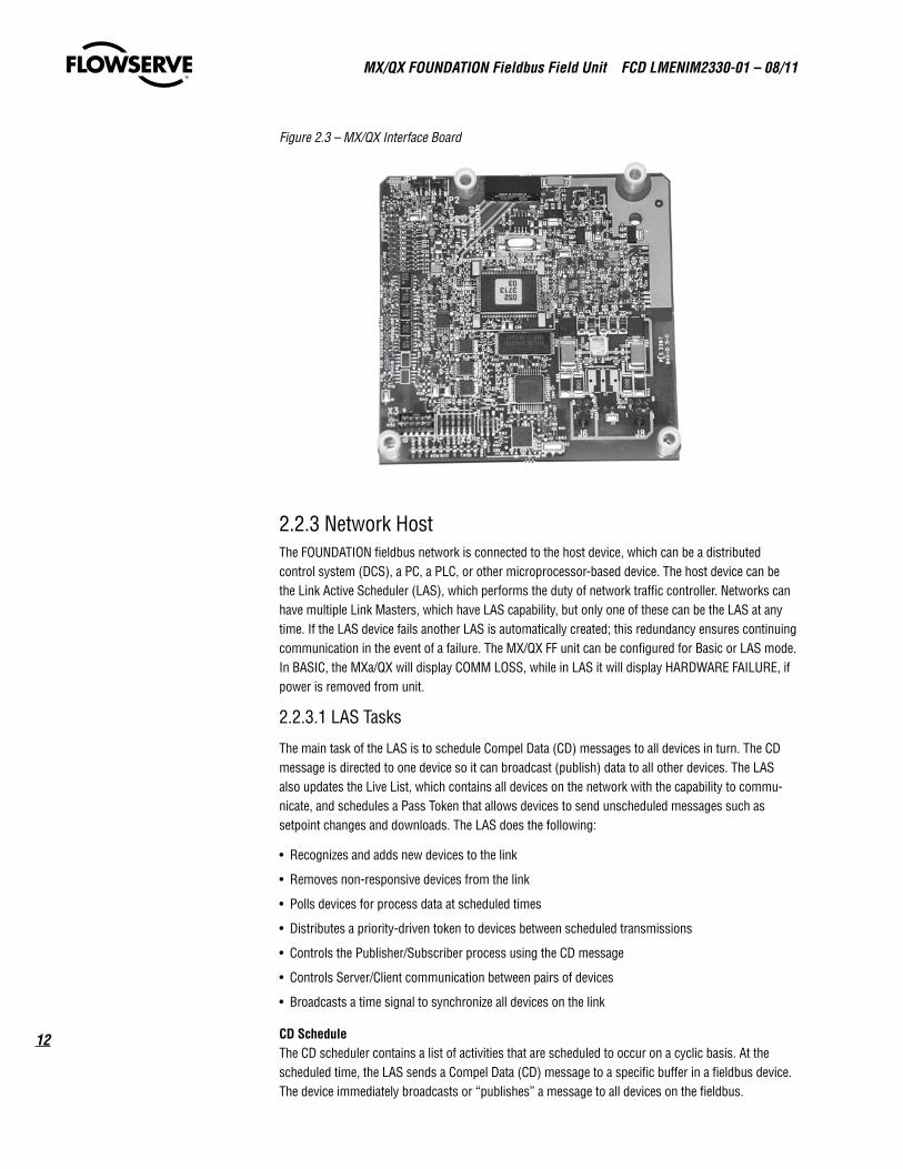
Figure 2.3 – MX/QX Interface Board
2.2.3 Network Host The FOUNDATION fieldbus network is connected to the host device, which can be a distributed control system (DCS), a PC, a PLC, or other microprocessor-based device. The host device can be the Link Active Scheduler (LAS), which performs the duty of network traffic controller. Networks can have multiple Link Masters, which have LAS capability, but only one of these can be the LAS at any time. If the LAS device fails another LAS is automatically created; this redundancy ensures continuing communication in the event of a failure. The MX/QX FF unit can be configured for Basic or LAS mode. In BASIC, the MXa/QX will display COMM LOSS, while in LAS it will display HARDWARE FAILURE, if power is removed from unit.
2.2.3.1 LAS Tasks
The main task of the LAS is to schedule Compel Data (CD) messages to all devices in turn. The CD message is directed to one device so it can broadcast (publish) data to all other devices. The LAS also updates the Live List, which contains all devices on the network with the capability to commu-nicate, and schedules a Pass Token that allows devices to send unscheduled messages such as setpoint changes and downloads. The LAS does the following:
• Recognizes and adds new devices to the link
• Removes non-responsive devices from the link
• Polls devices for process data at scheduled times
• Distributes a priority-driven token to devices between scheduled transmissions
• Controls the Publisher/Subscriber process using the CD message
• Controls Server/Client communication between pairs of devices
• Broadcasts a time signal to synchronize all devices on the link
CDScheduleThe CD scheduler contains a list of activities that are scheduled to occur on a cyclic basis. At the scheduled time, the LAS sends a Compel Data (CD) message to a specific buffer in a fieldbus device. The device immediately broadcasts or “publishes” a message to all devices on the fieldbus.
13
MX/QX FOUNdaTION Fieldbus Field Unit FCd LMENIM2330-01 – 08/11
flowserve.com
UnscheduledCommunicationAll devices on the fieldbus are given a chance to send “unscheduled” messages between transmis-sions of scheduled messages. The LAS grants permission to a device to use fieldbus by sending a pass token (PT) message to the device. Upon receipt of the PT, the device is allowed to send messages until the token hold time has expired.
LiveListMaintenanceThe list of all devices that are properly responding to the pass token is called the “Live List.” New devices may be added to the fieldbus at any time. The LAS periodically sends Probe Node (PN) messages to the addresses not in the Live List. If a device is present at the address and receives the PN, it immediately returns a Probe Response (PR) message, and the LAS adds the device to the Live List.
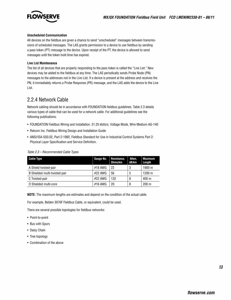
2.2.4 Network Cable Network cabling should be in accordance with FOUNDATION fieldbus guidelines. Table 2.3 details various types of cable that can be used for a network cable. For additional guidelines see the following publications:
• FOUNDATION Fieldbus Wiring and Installation. 31.25 kbits/s, Voltage Mode, Wire Medium AG-140
• Relcom Inc. Fieldbus Wiring Design and Installation Guide
• ANSI/ISA-S50.02, Part 2-1992, Fieldbus Standard for Use in Industrial Control Systems Part 2: Physical Layer Specification and Service Definition.
Table 2.3 – Recommended Cable Types
CableType GaugeNo. Resistance,Ohms/km
Atten,dB/km
MaximumLength
A Shield twisted-pair #18 AWG 22 3 1900 m
B Shielded multi-twisted pair #22 AWG 56 5 1200 m
C Twisted-pair #22 AWG 132 8 400 m
D Shielded multi-core #16 AWG 20 8 200 m
NOTE: The maximum lengths are estimates and depend on the condition of the actual cable.
For example, Belden 3076F Fieldbus Cable, or equivalent, could be used.
There are several possible topologies for fieldbus networks:
• Point-to-point
• Bus with Spurs
• Daisy Chain
• Tree topology
• Combination of the above
MX/QX FOUNdaTION Fieldbus Field Unit FCd LMENIM2330-01 – 08/11
14
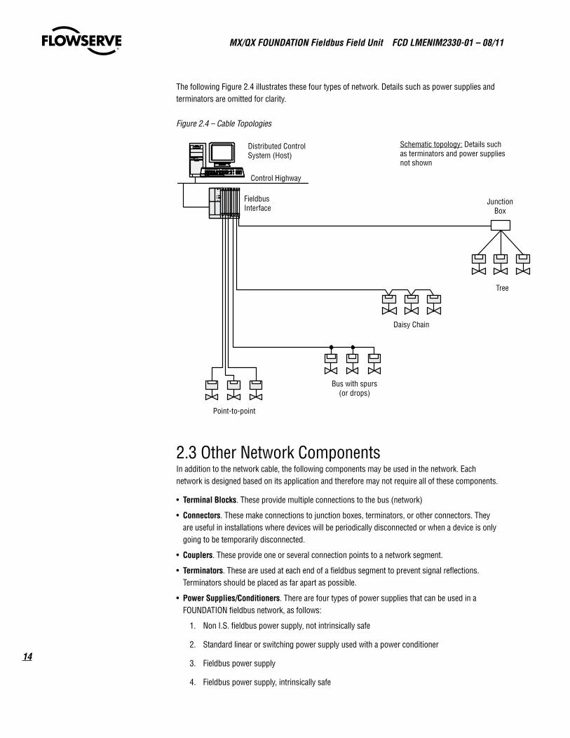
The following Figure 2.4 illustrates these four types of network. Details such as power supplies and terminators are omitted for clarity.
Figure 2.4 – Cable Topologies
2.3 Other Network Components In addition to the network cable, the following components may be used in the network. Each network is designed based on its application and therefore may not require all of these components.
• TerminalBlocks. These provide multiple connections to the bus (network)
• Connectors. These make connections to junction boxes, terminators, or other connectors. They are useful in installations where devices will be periodically disconnected or when a device is only going to be temporarily disconnected.
• Couplers. These provide one or several connection points to a network segment.
• Terminators. These are used at each end of a fieldbus segment to prevent signal reflections. Terminators should be placed as far apart as possible.
• PowerSupplies/Conditioners. There are four types of power supplies that can be used in a FOUNDATION fieldbus network, as follows:
1. Non I.S. fieldbus power supply, not intrinsically safe
2. Standard linear or switching power supply used with a power conditioner
3. Fieldbus power supply
4. Fieldbus power supply, intrinsically safe
FieldbusInterface
Control Highway
Distributed ControlSystem (Host)
JunctionBox
Tree
Daisy Chain
Bus with spurs(or drops)
Point-to-point
Schematic topology: Details suchas terminators and power suppliesnot shown
15
MX/QX FOUNdaTION Fieldbus Field Unit FCd LMENIM2330-01 – 08/11
flowserve.com
Power Conditioners are power supply impedance matching networks and are required. For additional details see FOUNDATION Fieldbus Wiring and Installation 31.25 kbits/s, Voltage Mode, Wire Medium AG-140, available on the web at www.fieldbus.org.
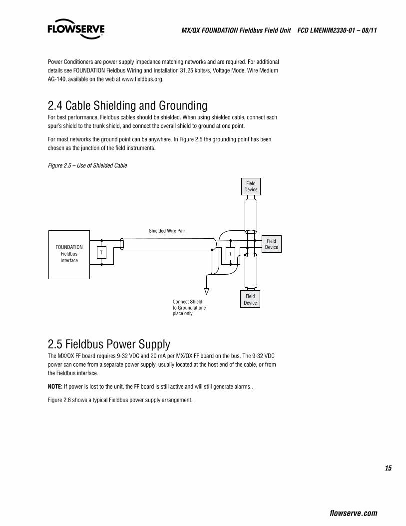
2.4 Cable Shielding and Grounding For best performance, Fieldbus cables should be shielded. When using shielded cable, connect each spur’s shield to the trunk shield, and connect the overall shield to ground at one point.
For most networks the ground point can be anywhere. In Figure 2.5 the grounding point has been chosen as the junction of the field instruments.
Figure 2.5 – Use of Shielded Cable
2.5 Fieldbus Power Supply The MX/QX FF board requires 9-32 VDC and 20 mA per MX/QX FF board on the bus. The 9-32 VDC power can come from a separate power supply, usually located at the host end of the cable, or from the Fieldbus interface.
NOTE: If power is lost to the unit, the FF board is still active and will still generate alarms..
Figure 2.6 shows a typical Fieldbus power supply arrangement.
FOUNDATIONFieldbusInterface
Shielded Wire Pair
Connect Shieldto Ground at oneplace only
TT
FieldDevice
FieldDevice
FieldDevice

MX/QX FOUNdaTION Fieldbus Field Unit FCd LMENIM2330-01 – 08/11
16
Figure 2.6 – Fieldbus Power Supply with External Termination
Figure 2.7 – Fieldbus Power Supply with MX/QX FF Termination
2.6 Site and Network Cable Preparation 2.6.1 Site PreparationPrepare the site and associated equipment for operation of the MX/QX FF controlled MX/QX actuators as follows:
1. Prepare a detailed site plan consisting of the following:
• Actuator locations and tag numbers
• Junction boxes and terminal strip locations and tag numbers
• Terminators and power supplies/conditioners, and repeaters
• Provide free access to the MX/QX control panel and terminal block for setup, configuration, and troubleshooting.
TFOUNDATION
FieldbusInterface
+
-
FieldbusPowerSupply
Shielded Wire Pair
T
FieldDevice
FieldDevice
FieldDevice
TFOUNDATION
FieldbusInterface
+
-
FieldbusPowerSupply
Shielded Wire Pair Field Device
FieldDevice
FieldDevice
T

17
MX/QX FOUNdaTION Fieldbus Field Unit FCd LMENIM2330-01 – 08/11
flowserve.com
2. Prepare the cable and label all wires. See Section 2.6.2.
3. Install power and control wires in separate conduits.
4. Install and verify earth grounds. The cable shields should be tied together. Ground the fieldbus shield only at one point. The MX/QX FF unit should not connect either conductor of the cable to ground at any point in the network. Refer to Section 2.4 - Cable Grounding.
NOTE: Limitorque defines an effective local earth ground as a low impedance (less than 5 ohms) path to either:
• A ground electrode placed in the close vicinity of the actuator, which is free of ground loop currents. OR
• A safety ground that is free of ground loop currents running from the actuator back to the system ground electrode. If the signal wiring is run on aerial cable where it may be exposed to high energy electrostatic discharge (such as lightning), a low impedance path to ground which is capable of high current must be provided a short distance from the actuator as described above. OR
• A power distribution grid identifying the impact of power isolation to a particular actuator or group of actuators should be provided.
2.6.2 Network Cable Preparation Care must be taken during cable preparation:
• When stripping the insulation, use wire strippers that do not nick the wire.
• Use crimp ferrules to prevent stranded wires from getting loose and shorting to other wires.
• Use vibration resistant wiring terminals that hold the ferrule securely.
2.6.2.1 Network Cable Connection to the MX/QX FF Unit The field device is connected to the network through the MX/QX terminal block. The network cable is connected to terminal block as shown in Figure 2.8.
NOTE: The MX/QX FF device is sensitive to polarity. The cables should indicate polarity and polarity should be maintained through all connection points.
Figure 2.8 – Network Cable Connections to Terminal Blocks
Network data-FF1(-)Network data-FF1(+)
Network data-FF1(-)Network data-FF1(+)
Terminal block345
1413
A
B
MX/QX FOUNdaTION Fieldbus Field Unit FCd LMENIM2330-01 – 08/11
18
NOTE:
• Shielded twisted-pair cables are used.
• Shields are connected to earth ground at only one point in the segment to avoid ground loops.
• Clean earth-ground connection (less than 5 ohms) provides noise protection and a clear, safe path for surge currents.
Prepare the network cable for connection to the MX/QX terminals a follows:
a CAUTION: Strip stranded conductors carefully; do not damage the strands. This will weaken the conductor. Do not nick conductors when stripping away the insulation. Nicking stresses the conductor and can cause the conductor to break. This type of damage may not be apparent and failure can occur later without warning.
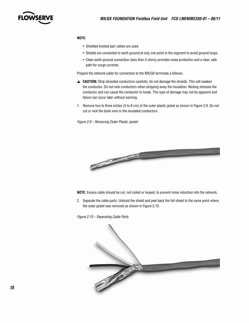
1. Remove two to three inches (5 to 8 cm) of the outer plastic jacket as shown in Figure 2.9. Do not cut or nick the drain wire or the insulated conductors.
Figure 2.9 – Removing Outer Plastic Jacket
NOTE: Excess cable should be cut, not coiled or looped, to prevent noise induction into the network.
2. Separate the cable parts. Unbraid the shield and peel back the foil shield to the same point where the outer jacket was removed as shown in Figure 2.10.
Figure 2.10 – Seperating Cable Parts

19
MX/QX FOUNdaTION Fieldbus Field Unit FCd LMENIM2330-01 – 08/11
flowserve.com
3. Cut away the foil shield. Strip the insulation from the conductors approximately 0.4 inch (1 cm) as shown in Figure 2.11.
Figure 2.11 – Stripping Conductors
Figure 2.12 – Applying Heat Shrink Tubing
4. Apply heat shrink tubing to insulate the braided shield and to provide stress relief to the cable as shown in Figure 2.12.
a CAUTION: Do not melt the insulation.
5. Install ring tongue connectors as shown in Figure 2.13.
NOTE: Flowserve recommends the use of Thomas and Betts #RZ22-6 for optimum results.
Figure 2.13 – Ring tongue connectors

MX/QX FOUNdaTION Fieldbus Field Unit FCd LMENIM2330-01 – 08/11
20
6. Connect the network cables to the MX/QX terminal block as shown in Figure 2.14.
Table 2.4 details a connection for the daisy chain topology. If the actuator is to be connected on a spur (as a drop), use only terminals 15 and 16.
Table 2.4 – Loop Topology Connection TerminalBlockNumber Function
4 FF1 (-)
5 FF1 (+)
14 FF1 (-)
13 FF1 (+)
3 Surge Protection
NOTE: Ground each segment of the cabling at only one point to prevent ground loops that can affect system performance, see Section 2.4. Verify the actuator is properly grounded.
7. Connect the cable shields toeach other inside the unit. Do not connect then to the unit in any way. The network shield should be grounded at only one place in the network. If it is desired to ground the entire network shield at the actuator, then install a jumper cable from terminal 3 to earth ground or ground lug.
Figure 2.14 – Connecting Network Cable to MX/QX Terminal Block

21
MX/QX FOUNdaTION Fieldbus Field Unit FCd LMENIM2330-01 – 08/11
flowserve.com
2.6.2.2 Network Cable Connections to Other Network Components Each FOUNDATION fieldbus network may require some or all of the following components depending on the application:
• Junction Box/Terminal Blocks
• Connectors
• Power Supplies
• Power Conditioners
• Terminators
• Intrinsic Safety Barriers
• Bridge and Repeaters
For cable connecting information on these components, see the following:
• FOUNDATION Fieldbus Wiring and Installation 31.25 kbits/s, Voltage Mode, Wire Medium AG-140
• Relcom Inc. Fieldbus Wiring Design and Installation Guide
• ANSI/ISA-S50.02, Part 2-1992, Fieldbus Standard for Use in Industrial Control Systems Part 2: Physical Layer Specification and Service Definition
2.6.2.3 Cable Length and Number of Devices Requirements The network cable consists of a trunk, segments, and spurs. The trunk is the main connection between all the devices. A segment is a section of the cable that contains the terminators. A spur connects to the trunk through a junction box. The following topologies are possible:
• Point-to-point
• Bus with Spurs
• Daisy Chain
• Tree topology
• Combination of the above
Figure 2.15 – Network with Spurs
T
FieldbusI/O
Control Highway
DCS(Host)
Terminator JunctionBoxFieldbus Trunk
Spur
Spur
T
Terminator
MX/QX FF
Actuator
MX/QX FF
Actuator
MX/QX FF
ActuatorMX/QX FF
Actuator

MX/QX FOUNdaTION Fieldbus Field Unit FCd LMENIM2330-01 – 08/11
22
The maximum length of the fieldbus cable is determined by the following:
• Communication rate
• Cable type
• Wire size
• Bus power option
• Intrinsic safety option
The maximum number of devices on the MX/QX FF fieldbus segment is based on the following:
• The communication rates of the devices
• The maximum number of addresses on a segment.
• The available power
Table 2.5 – Recommended Maximum Spur Length, m (ft) Spur Length m (ft)
TotalDevicesperNetwork
1DeviceperSpur
2DevicesperSpur
3DevicesperSpur
4DevicesperSpur
25-32 1 (3) 1 (3) 1 (3) 1 (3)
19-24 30 (98) 1 (3) 1 (3) 1 (3)
15-18 60 (197) 30 (98) 1 (3) 1 (3)
13-14 90 (295) 60 (197) 30 (98) 1 (3)
1-12 120 (394) 90 (295) 60 (197) 30 (98)
For further details on maximum cable length and number of devices, see the fieldbus references listed in Section 2.6.2.2.
2.6.2.4 Network Cable Connection to the Host System (DCS) For instructions on connecting to the DCS, see the applicable DCS instruction manual. There are several possible topologies for the network as detailed in FOUNDATION Fieldbus Application Guide AG-140, 31.25 kbits/s, Wiring and Installation.
2.6.3 MX/QX FF Device Installation The MX/QX FF board is located in the electrical housing. The board has four standoffs and mounts on top of the main processor board. If the I/O board option is present, the I/O board will be on top of the MX/QX FF board. For installation instructions, refer to the MX Maintenance and Spare Parts Manual, LMENIM2314 or the QX Maintenance and Spare Parts Manual LMENIM3314.
2.6.4 MX/QX FF Device Setup The MX/QX FF option enables the actuator to be controlled by a Foundation fieldbus communications signal. If the option has been purchased, it is automatically enabled.
NOTE: If the FF option has not been purchased, the screens for changing FF will not be available. To add the FF option, please consult Limitorque service at (434) 528-4400.
Figure 2.16 illustrates the setup sequence. For proper operation either Position Mode or Open/Close Mode must be selected.

23
MX/QX FOUNdaTION Fieldbus Field Unit FCd LMENIM2330-01 – 08/11
flowserve.com
Figure 2.16 – MX/QX FF Setup Sequence
NOTE: This menu is displayed after the actuator and FF board have been powered up together at least one time.
To setup the MX or QX FF device, enter the Setup mode as detailed in Installation and Operation Manual Bulletins LMENIM2306 for the MX and LMENIM3306 for the QX:
1. Proceed through Setup to the CHANGE FF? display. Select YES to get to the STATUS display.
2. STATUS enables the user to change from the default condition to turn on and off the digital control capability of the actuator. Select NO to change the setting or YES to get to the next display. (Default = ON)
3. ESD ACTION allows a network ESD function to be enabled after the ESD configuration has been established for the unit. This network ESD can be selected to do one of the following: ignore the command (NONE), CLOSE, OPEN, STOP, or POSITION the actuator. To change from the default setting, select NO until the required option is displayed. Select YES if the setting is correct to go to the next display.
NOTE: if POSITION is chosen as the action, a MOVE TO display will be shown where the user can select the desired position between 0 and 100% open, in one percent increments, by selecting NO until the desired position is selected. Select YES once the setting is correct to go to the next display.
4. COMM LOSS ACTION allows the user to select the action to be taken after a communica-tion loss to the actuator. The action can be one of the following: no action (NONE), CLOSE, OPEN, STOP, or POSITION the actuator. To change from the default setting, select NO until the required option is displayed. Select YES if the setting is correct to go to the next display. (Default = NONE)
NOTE: if POSITION is chosen as the action, a MOVE TO display will be shown where the user can select the desired position between 0 and 100% open, in one percent increments, by selecting NO until the desired position is selected. Select YES once the setting is correct to go to the next display.
5. COMM LOSS DELAY sets the time before which the COMM LOSS ACTION is taken after a communication loss. The setting can be between 0 - 120 seconds (2 min) seconds in one-second increments. To change from the default, select NO until the required value is displayed. Select YES if the setting is correct to go to the next display.
NO (OFF)
YES
NO NO
NO
YES
YESYES YES
(1%-100%)1% Increments
(1%-50%)1% Increments
CHANGE FF?
STATUS (ON)-OK?
YES
CHANGE PROP/DEADBAND?
NO
YES
DEADBAND(2%)-OK?
PROP BAND(15%)-OK?
NO
OPEN/CLOSEMODE-OK?
POSITIONMODE-OK?
(CLOSE)(OPEN)(STOP)
(POSITION)
YES
NO
ESD ACTION(IGNORE)-OK?
(CLOSE)(OPEN)(STOP)
(POSITION)
YES YES
NO
COMM LOSS ACTION(NONE)-OK?
(0-4095)NO
COMM LOSS DELAY(60 SEC)-OK?
(0-100%)
** YES
NO
MOVE TOXXX% OPEN
(0-100%)
YES
NO
MOVE TOXXX% OPEN
* If POSITION is chosen, as action, this menu will appear.

MX/QX FOUNdaTION Fieldbus Field Unit FCd LMENIM2330-01 – 08/11
24
6. OPEN/CLOSE or POSITION display allows selection of the mode of operation of the actuator. To select operation as typically OPEN or CLOSE, select YES with OPEN/CLOSE MODE-OK? on the display (this is the default), this will return the actuator to the CHANGE FF? display.
In position mode the host device can set the valve position to any desired value; in open/close mode the host can only fully open or fully close the valve. The user must locally configure one of these two modes. To select operation in POSITION mode, select NO to change the display to POSITION MODE-OK? and then select YES. This will allow the user to configure the proportional band and deadband as discussed below. (Default = OPEN/CLOSE)
2.6.4.1 Proportional Band Proportional band is the range of errors between the position and demand signal that will produce reduced speed (pulsing). The default value is 15%.
To change from default, select NO until the required value is displayed. The value is adjustable between 1% and 100%, in 1% increments.
2.6.4.2 Deadband The default deadband value is 2%. For error signals less than this, no motion occurs.
The deadband should be wide enough to prevent “hunting” of the actuator but as low as possible to give adequate response to changes in the error signal. To change from the default, select NO to adjust the value between 1% and 50%, in 1% increments to suit the application.
2.6.5 Valve Data Valve data may be stored in the MX/QX FF transducer block for use by the host system. Refer to Bulletin LMENIM2306 for the MX and LMENIM3306 for the QX for instructions to edit data for the valve serial number, model and type.
2.7 MX/QX FF Device Description, Capabilities, and Device Type Manager Files Installation
2.7.1 MX/QX FF Device Description and Capabilities FilesA Capabilities File (CF) describes the communication objects in a fieldbus device. In the Host system, the configuration device can use DD files or CF files to configure a fieldbus system without having the fieldbus devices online. Some host systems need both DD and CF files. Refer to your host system documentation for the files that are needed.
The DTM file provides an interface between the actuator’s specific application software and a Network Host Station’s Field Device Tool (FDT) frame. The DTM can be integrated into FDT frame applications to allow users to perform offline and online parameterization, configuration, and status and diag-nostic retrieval.
The DD files are downloaded from the Fieldbus web site (www.fieldbus.org) into the DCS workstation or host device.
In addition, the DD and DTM files can be downloaded from the Flowserve Limitorque web site: www.flowserve.com

25
MX/QX FOUNdaTION Fieldbus Field Unit FCd LMENIM2330-01 – 08/11
flowserve.com
2.8 Installation Verification
2.8.1 Network Cabling Installation Verification After installation is complete and prior to operation, inspect the network cable and its connection to each field device.
NOTE: Units should be disconnected from power. The network should be disconnected from the host device.
Check for the following:
1. There should not be:
• Nicks in the insulation - this can cause a short to the grounded shield.
• Cut strands in a stranded conductor - this can cause a poor connection and eventually an open circuit.
2. Cable armor shorted to the cable shield/drain wire this may not be at ground potential and could be subject to lightning surges.
3. The Shield/drain wire should only be grounded at one point in the segment to avoid ground loop problems.
4. The ground/earth connection should be at true ground potential and effective at all times. See No. 5 in Section 2.6.1, Site Preparation.
2.8.2 MX/QX FF Device Installation Verification Verify the field device is installed as follows:
1. Enter the Setup mode as detailed in Installation and Operation Manual Bulletins LMENIM2306 for the MX or LMENIM3306 for the QX
2. In the Setup mode, use the black control knob to select YES to the main menu selection VIEW DIAGNOSTICS?
3. Select YES to the display VIEW HARDWARE STATUS?
4. Select YES to scroll through the menu selections. The LCD will read FF (OK) - NEXT? if installed.
NOTE: If the FF (OK) - NEXT? does not appear, contact Limitorque for assistance.
5. To return to the normal display, use the black knob to select either LOCAL or REMOTE.
2.9 Configuration Confirmation Field device operation cannot be verified until the complete Fieldbus system is operational. However, routine checks can be performed to verify many functions.
2.9.1 Checking Connections Verify that all connections, including data wires, shield ground, digital inputs (optional), digital outputs (optional), and analog inputs (optional) are in accordance with MX/QX wiring diagrams and MX/QX FF device diagrams in Section 2.6.

MX/QX FOUNdaTION Fieldbus Field Unit FCd LMENIM2330-01 – 08/11
26
2.9.2 View Settings Refer to Installation and Operation Manual Bulletins LMENIM2306, for the MX and LMENIM3306 for the QX to access the view settings menu. Verify the settings as follows:
1. From the VIEW SETTINGS display, scan to the VIEW FF? display
2. From VIEW FF? display, select YES and check that the FF status is ON. This confirms that FF is enabled.
3. If the MX/QX contacts are to be controlled via the network to control external equipment, from the VIEW FF? display, select NO and obtain the VIEW STATUS AND ALARM CONTROL? display. Verify that the digital outputs, S1a, S1b, S2a, S2b are set for “Network” controlled.
2.9.3 Checking the Normal Display Place the selector switch in LOCAL or REMOTE position. The valve position will be indicated at the top of the LCD. STATUS OK or FF COMM LOSS should be indicated at the bottom of the LCD display.
• If STATUS OK is displayed, then the field device is communicating with the LAS.
• If FF COMM LOSS is displayed, no communication is occurring. This could be due to a number of factors, including problems with the Host/Master station and/or the network. Check all local connections and configurations. If these are correct and the FF COMM LOSS is still displayed, then the solution to this problem must await full system commissioning.
Figure 2.17 – Normal Display
Remote
Local
or
Remote
Field unit is communicating with host/master station
Bus power and no communication
No bus power
Local
or
Remote
Local
or100% OPENSTATUS OK
100% OPEN 100% OPENFF COMM LOSS HARDWARE FAILURE
27
MX/QX FOUNdaTION Fieldbus Field Unit FCd LMENIM2330-01 – 08/11
flowserve.com
3Software
3.1 Fieldbus Protocol The fieldbus system uses the FOUNDATION fieldbus protocol to communicate over the H1 Fieldbus network with other Fieldbus devices. The signals are encoded using the Manchester Biphase-L technique. The signal is called synchronous serial because the clock information is embedded in the serial stream. The protocol uses built-in error checking rules when processing data.
3.2 Fieldbus Function Blocks The user application layer is programmed using software function blocks located in the device. The function blocks provide the interface with the actuator and process, and the interface with the network and control system.
The user layer in each device contains the following:
• One resource block
• One Transducer block for the inputs and outputs
• Function blocks for analog I/O and digital I/O
• Function Block for Proportional Integral Derivative (PID) Control
The Resource Block describes the hardware specific characteristics associated with the actuator and its associated blocks; it has no inputs or outputs. Data in the Resource Block includes the following:
• Manufacturer’s name
• Device name
• Serial number
The Transducer Block represents local connection for the physical I/O. It connects function blocks to the local inputs and outputs. It reads sensor hardware and writes to actuator hardware. The Transducer Block executes as frequently as necessary to obtain good data from sensors and ensures proper writes to the actuator without burdening the function blocks that use the data.

MX/QX FOUNdaTION Fieldbus Field Unit FCd LMENIM2330-01 – 08/11
28
Figure 3.1 – Fieldbus Function Blocks
A Virtual Field Device (VFD) is used to remotely view local device data described in the object dictionary. The VFD in each device is used for network management and system management, and contains configuration information such as function block schedules.
The Function Blocks provide the control and I/O behavior of the device. They perform analog to digital conversion, linearization; and transmit information to and from other function blocks. Function Blocks are connected together during the configuration to perform the specific control functions of the process, and communicate with the host device, which supervises the entire control system.
Table 3.1 – Description of the Function Blocks
FunctionBlock Name No.ofBlocks Description
Analog Input AI 1 Processes field device measurements and makes them available to other function blocks; supports alarming, filtering, signal status, mode control, and simulation.
Analog Output AO 1 Assigns an analog setpoint value to a field device through a transducer block I/O channel; supports mode control, signal status calculation, and simulation.
Discrete Input DI 4 Processes a single discrete input from a field device and makes it available to other function blocks; supports alarming, signal status propagation, mode control, and simulation.
Discrete Output DO 2 Processes a discrete setpoint and outputs it to a specified I/O channel to produce an output signal; supports mode control, output tracking, and simulation.
Transducer Block 1 A custom block to monitor and control the actuator; connects function blocks to local input/output functions.
PID Block PID 1 Combines all necessary logic algorithms to perform process control; supports mode control, signal scaling and limiting, feed forward control, override tracking, alarm limit detection and signal status propagation.
Resource Block 1 A standard block to provide general management of the device.
Standard Fieldbus parameters used in these blocks are listed in Appendix C.
3.3 Analog Input Function Block The Analog Input (AI) function block (Figure 3.2) is a standard block over all fieldbus systems. The AI block processes field measurements and makes them available to other function blocks. The output value from the AI block is in engineering units and contains a status indicating the quality of the
Communication
Resource Block
AI Blocks
DO Blocks
AO Blocks
DI Blocks
Actuator
FieldbusNetwork
ActuatorI/O
TransducerBlock
FunctionBlocks
PID Blocks

29
MX/QX FOUNdaTION Fieldbus Field Unit FCd LMENIM2330-01 – 08/11
flowserve.com
measurement. The measuring device may have several measurements or derived values available in different channels. Use the Channel number to define the desired variable from the transducer block.
There is one AI block in the Limitorque actuator control system, and two channels:
Channel No.12 — AI_POSITION_CHAN — Current valve position
Channel No.13 — AI_ANALOG_INPUT_1_CHAN — Value of analog input 1
Figure 3.2 – Analog Input Block
The AI block supports alarming, signal scaling, signal filtering, signal status calculation, mode control, and simulation. In Automatic mode, the block’s output reflects the Process Variable (PV) Value and Status. In Manual Mode, Output may be set manually by the operator. Manual Mode is reflected on the Output Status. Alarms can be generated based on the value of the block output.
OutputOUT is the block output value and status.
ScalingTransducer scaling (XD_SCALE) is applied to the value from the channel to produce the FIELD_VAL in percent. The XD_SCALE units code must match the channel units code (if one exists), or the block will remain in O/S mode after being configured. A block alarm for units mismatch will be generated.
The OUT_SCALE is normally the same as the transducer, but if L_TYPE is set to Indirect or Indirect Square Root, OUT_SCALE determines the conversion from FIELD_VAL to the output. PV and OUT always have identical scaling.
OUT_SCALE provides scaling for PV. The PV is always the value that the block will place in OUT if the mode is Auto.
ManualModeIf Man is allowed, someone may write a value to the output. The status will prevent any attempt at closed loop control using the Man value, by setting the Limit value to Constant.
LowCutoffThe LOW_CUT parameter has a corresponding “Low cutoff” option in the IO_OPTS bit string. If the option bit is true, any calculated output below the low cutoff value will be changed to zero. This is only useful for zero based measurement devices, such as flow.
Output
AlarmsHI/LO
OUT(to network)
SimulateSIMULATE
Analogmeasurement
AnaIog Input Block
FilterPV_FTIME
PV
ConvertL_TYPE
XD_SCALEOUT_SCALE
CutoffLOW_CUT
Mode
FIELD_VAL
(from actuator)

MX/QX FOUNdaTION Fieldbus Field Unit FCd LMENIM2330-01 – 08/11
30
FilterThe PV filter, whose time constant is PV_FTIME, is applied to the PV, and not the FIELD_VAL.
SimulationSimulation is used to support testing. Simulation can be enabled through the configuration tool and allows the manual entry of a value for a measurement and its status.
This feature requires the installation of a hardware jumper on the MX/QX FF unit, located on header X5 Pins 7 and 8.
3.4 Analog Output Function Block The Analog Output (AO) block assigns an output value to a field device through a specified transducer block I/O channel. The block supports mode control, signal limiting, rate limiting, signal status calculation, and simulation. There are provisions to ensure bumpless mode transfer when this block is part of a control loop.
There is one AO block in the Limitorque actuator control system:
Channel No.1 — AO_CTRL_VALVE_FLOW_CHAN — Desired valve position %
Figure 3.3 – Analog Output Block
The output can be set in four ways. In Manual Mode, the output can be set by the user, and this value is independent of the Setpoint. In Automatic Mode, the output is set by the Setpoint value in engineering units and the I/O options parameter. In Cascade Mode, the Cascade Input value from another block is used to update the Setpoint. In Remote Cascade Mode, the setpoint comes from a remote computer or DCS. The Setpoint value can be limited, and also the rate at which the setpoint output changes can be limited.
To provide bumpless transfer on mode changes and windup protection if there is an upstream PID block, the Back Calculation Out parameter is used, and various block I/O options.
InputsCAS_IN is the remote setpoint from another function block.
OUT (toTransducerblock)
Analog Output BlockCAS_IN
RCAS_IN
SetpointSP_RATE_DNSP_RATE_UPSP_HI_LIMSP_LO_LIM
Out Convert
PV_SCALEXD_SCALE
Output
MODE
SHED_OPT
SP
PV Convert
XD_SCALEPV_SCALE
PV
Fault State
FSTATE_TIMEFSTATE_VAL
Simulate
SIMULATE
CHANNELDATA (fromtransducer)
READBACK
BKCAL_OUT
RCAS_OUT

31
MX/QX FOUNdaTION Fieldbus Field Unit FCd LMENIM2330-01 – 08/11
flowserve.com
RCAS_IN is a target setpoint and status provided by a supervisory host to an analog control or output block.
OutputsOUT is the block output and status.
RCAS_OUT is a block setpoint and status after ramping, provided to a supervisory host for back calculation and to allow action to be taken under limiting conditions or mode change.
BKCAL_OUT is the value and status required by the BKCAL_IN of another block to prevent windup and to provide bumpless transfer to closed loop control.
ScalingThe PV_SCALE range is used to convert the SP to percent of span. The XD_SCALE range is used to convert percent of span to the number used by the hardware. This allows portions of the SP span to cause full span movement of the output. The Increase to close option in IO_OPTS can be used to invert the span.
CascadeOperationThe SP supports the full cascade sub-function. In fact, Cas mode must be used to transfer the output of another block to the SP of the AO. The SP has standard ramp rate and absolute limits. There are additional I/O options which will cause the SP value to track the PV value when the block is in an actual mode of LO or Man. If the Output Readback feature is turned on, such as valve position, that value should be run backwards through the XD scaling to act as the PV for this block. If not supported, READBACK is generated from OUT. The OUT and READBACK parameters both use XD_SCALE. The PV and SP use PV_SCALE.
Since the Analog Output block interfaces to the transducer block, there is no BKCAL_IN parameter. ROut mode is not supported.
For the BKCAL_OUT value, there is an option to use either the SP value after limiting, or the PV value.
SupportedModesO/S, LO, IMan, Man, Auto, Cas, and Rcas modes are supported. The Man mode can be used in maintenance or troubleshooting where the OUT value may need to be adjusted directly. This requires that the manufacturer put operational limits in the transducer block, where they are not accessible to an operator.
SimulationSimulation is used to support testing. Simulation can be enabled through the configuration tool and allows the manual setting of the channel feedback.
This feature requires the installation of a hardware jumper on the MX/QX FF unit, located on header X5 Pins 7 and 8.
3.5 Discrete Input Function Block The Discrete Input (DI) function block processes a single discrete input from a field device and makes it available to other function blocks. The user can configure alarm detection and inversion on the input signal. The DI block supports mode control, signal status propagation, and simulation.
There are four DI blocks in the Limitorque actuator control system, and seven channels:
Chan. No.2 — DI_POSITION_AND_BUS_MODE_CHAN — Valve status and control mode
Chan. No.3 — DI_POSITION_CHAN — Valve status, moving/stopped

MX/QX FOUNdaTION Fieldbus Field Unit FCd LMENIM2330-01 – 08/11
32
Chan. No.4 — DI_ACTUATOR_FAULTS_1_CHAN — Mechanical and electrical faults 1
Chan. No.5 — DI_ACTUATOR_FAULTS_2_CHAN — Mechanical and electrical faults 2
Chan. No.6 — DI_ACTUATOR_ALARMS_CHAN — Emergency shutdown and inhibits
Chan. No.7 — DI_DISC_USER_INPUT_CHAN — Discrete input from user
Chan. No.8 — DI_READ_DISC_OUTPUT_CHAN — Read discrete output
Figure 3.4 – Discrete Input Function Block
Normally the block is used in Automatic Mode so that the Process Variable is copied to the Output. If necessary, the operator can change the mode to Manual, which disconnects the field signal and substitutes a manually entered value for the Output.
InputsThe discrete input comes from a transducer, as selected by the CHANNEL.
OutputsOUT_D is the block discrete output.
The FIELD_VAL_D shows the true on/off state of the hardware, using XD_STATE. The Invert I/O option can be used to do a Boolean NOT function between the field value and the output. A discrete value of zero(0) will be considered to be a logical zero(0) and an non-zero discrete value will be considered to be a logical (1) e.g. if invert is selected, the logical NOT of a non-zero field value would result in a zero(0) discrete output, the logical NOT of a zero field value would result in a discrete output value of one(1).
FilteringandScalingPV_FTIME may be used to set the time that the hardware must be in one state before it gets passed to the PV_D. The PV_D is always the value that the block will place in OUT_D if the mode is Auto. The PV_D and the OUT_D always have identical scaling. OUT_STATE provides scaling for PV_D.
SupportedModesO/S, Manual, and Auto modes are supported. If Manual is allowed, someone may write a value to OUT_D.
AlarmTypesStandard block alarm plus standard discrete alarm applied to OUT_D.
SimulationSimulation is used to support testing. Simulation can be enabled through the configuration tool and allows the manual setting of the measurement value through the Simulate parameter (SIMULATE_D). Alternatively the operator can change the block Mode to Manual and adjust the Output Value.
OUT_D
(Discrete Signalfrom Transducer)
Discrete Input Block
FIELD_VAL_D
THE CHANNELDATA
SimulateSIMULATE_D
OptionalInvert
FilterPV_FTIME
PV_D
AlarmsDISCMODE
Output

33
MX/QX FOUNdaTION Fieldbus Field Unit FCd LMENIM2330-01 – 08/11
flowserve.com
This feature requires the installation of a hardware jumper on the MX/QX FF unit, located on header X5 Pins 7 and 8.
3.6 Discrete Output (DO) Function Block The Discrete Output (DO) function block processes a single discrete setpoint and outputs it to a specified I/O channel to produce an output signal. The DO block supports mode control, output tracking, and simulation. There is no process alarm detection in the block. In operation, the DO func-tion block determines its setpoint, sets the output, and, as an option, checks a readback signal from the field device to confirm the physical output operation.
There are two DO blocks in the Limitorque actuator control system, and three channels:
Chan. No.9 — DO_POSITION_CHAN — Command Stop/Open/Close
Chan. No.10 — DO_ESD_CHAN — Command Emergency Shutdown
Chan. No.11 — DO_RELAY_CHAN — Command energize relays
Figure 3.5 – Discrete Output Function Block
To set the DO block output, the operator first sets the mode to define how the block obtains its output. In Cascade Mode, the setpoint equals the input value from another block. In Auto Mode, the setpoint is written to the block. In Manual Mode, the setpoint is written to the Output. In Remote Cascade Mode, the setpoint is determined by a host computer or DCS that writes to the RCAS input.
InputsCAS_IN_D is the remote (cascade) setpoint value from another function block.
RCAS_IN_D is a target setpoint and status provided by a supervisory host to a discrete control or output block.
OutputsOUT_D is the discrete output value and status.
BKCAL_OUT_D is the back calculation output value and status required by the BKCAL_IN_D input of another block for output tracking.
OUT_D
Discrete Output BlockCAS_IN_D
RCAS_IN_D
Setpoint Optional
Invert
Output
MODE
SHED_OPT
SP_D
Optional
Invert
PV_D
Fault State
FSTATE_TIMEFSTATE_VAL_D
Simulate
SIMULATE_D
CHANNELDATA
READBACK_D
BKCAL_OUT_D
RCAS_OUT_D
(Transducer)
MX/QX FOUNdaTION Fieldbus Field Unit FCd LMENIM2330-01 – 08/11
34
RCAS_OUT_D is a block setpoint and status provided to a supervisory host for back calculation and to allow action to be taken under limiting conditions or mode change.
SP_D is the discrete target block output value (setpoint).
The Invert I/O option can be used to do a Boolean NOT function between the SP_D and the hardware.
The SP_D supports the full cascade sub-function. Cas mode must be used to transfer the output of another block to the SP_D of the DO. There are additional I/O options which will cause the SP_D value to track the PV_D value when the block is in an actual mode of LO or Manual.
ReadbackIf the hardware supports a readback value, it is used for READBACK_D, which, after accounting for the Invert I/O option, acts as the PV_D for this block. If not supported, READBACK_D is generated from OUT_D. The OUT_D and READBACK_D parameters both use XD_STATE. The PV_D and SP_D use PV_STATE.
SupportedModesO/S, LO, Iman, Man, Auto, Cas, and RCas. The Man mode can be used to force the output, in a PLC sense.
AlarmTypesStandard block alarm.
SimulationSimulation is used to support testing. Simulation can be enabled through the configuration tool and allows the manual entry of the Readback Value and its Status. Alternatively the operator can change the block Mode to Manual and adjust the Output Value.
This feature requires the installation of a hardware jumper on the MX/QX FF unit, located on header X5 Pins 7 and 8.
3.7 Proportional Integral Derivative (PID) Function BlockThe Proportional Integral Derivative (PID) function block combines all necessary logic algorithms to perform process control. The block supports mode control, signal scaling and limiting, feed forward control, override tracking, alarm limit detection and signal status propagation.

35
MX/QX FOUNdaTION Fieldbus Field Unit FCd LMENIM2330-01 – 08/11
flowserve.com
Figure 3.6 – Proportional Integral Derivative Function Block
SetpointselectionandlimitingThe setpoint of the PID block is determined by the mode. One can configure the SP_HI_LIM and SP_LO_LIM parameters to limit the setpoint. In Cascade or Remote Cascade mode, the setpoint is adjusted by another function block or by a host computer, and the output is computed based on the setpoint.
In Automatic mode, the setpoint is entered manually by the operator, and the output is computed based on the setpoint. In Auto mode, one can also adjust the setpoint limit and the setpoint rate of change using the SP_RATE_UP and SP_RATE_DN parameters.
In Manual mode the output is entered manually by the operator, and is independent of the setpoint. In Remote output mode, the output is entered by a host computer, and is independent of the setpoint.
FilteringThe filtering feature changes the response time of the device to smooth variations in output readings caused by rapid changes in input. One can configure the filtering feature with the FILTER_TYPE parameter, and one can adjust the filter time constant (in seconds) using the PV_FTIME or SP_FTIME parameters. Set the filter time constant to zero to disable the filter feature.
FeedforwardcalculationThe feedforward value (FF_VAL) is scaled (FF_SCALE) to a common range for compatibility with the output scale (OUT_SCALE). A gain value (FF_GAIN) is applied to achieve the total feedforward contribution.
TrackingOne can enable the use of output tracking through the control options. One can set control options in Manual or Out of service mode only.
The track enable control option must be set to true for the track function to operate. When the track in Manual control option is set to true, tracking can be activated and maintained only when the block is in Manual mode. When track in Manual is false, the operator can override the tracking function when the block is in Manual mode. Activating the track function causes the block’s actual mode to revert to local override.

MX/QX FOUNdaTION Fieldbus Field Unit FCd LMENIM2330-01 – 08/11
36
The TRK_VAL parameter specifies the value to be converted and tracked into the output when the track function is operating. The TRK_SCALE parameter specifies the range of TRK_VAL.
When the TRK_IN_D parameter is true and the track enable control option is true, the TRK_VAL input is converted to the appropriate value and output in units of OUT_SCALE.
OutputselectionandlimitingOutput selection is determined by the mode and the setpoint. In Automatic, Cascade, or Remote cascade mode, the output is computed by the PID control equation. In Manual and Remote output mode, the output may be entered manually. One can limit the output by configuring the OUT_HI_LIM and OUT_LO_LIM parameters.
BumplesstransferandsetpointtrackingOne can configure the method for tracking the setpoint by configuring the following control options (CONTROL_OPTS):
SP-PV Track in Man — Permits the SP to track the PV when the target mode of the block is Man.
SP-PV Track in LO or IMan — Permits the SP to track the PV when the actual mode of the block is Local Override (LO) or Initialization Manual (IMan).
When one of these options is set, the SP value is set to the PV value while in the specified mode. One can select the value that a master controller uses for tracking by configuring the use PV for BKCAL_OUT control option. The BKCAL_OUT value tracks the PV value. BKCAL_IN on a master controller connected to BKCAL_OUT on the PID block in an open cascade strategy forces its OUT to match BKCAL_IN, thus tracking the PV from the slave PID block into its cascade input connection (CAS_IN). One can set control options in Manual or Out of service mode only. When the mode is set to Auto, the SP will remain at the last value (it will no longer follow the PV).
ResetLimitingThe PID function block provides a modified version of feedback reset limiting that prevents windup when output or input limits are encountered, and provides the proper behavior in selector applications.
ModesThe PID function block supports the following modes:
MANUAL (MAN)—The block output (OUT) may be set manually.
AUTOMATIC (AUTO)—The SP may be set manually and the block algorithm calculates OUT.
CASCADE (CAS)—The SP is calculated in another block and is provided to the PID block through the CAS_IN connection.
REMOTE CASCADE (RCAS)—The SP is provided by a host computer that writes to the RCAS_IN parameter.
REMOTE OUTPUT (ROUT)—The OUT IS provided by a host computer that writes to the ROUT_IN parameter.
LOCAL OVERRIDE (LO)—The track function is active. OUT is set by TRK_VAL. The BLOCK_ERR parameter shows Local override.
INITIALIZATION MANUAL (IMAN)—The output path is not complete (for example, the cascade-to-slave path might not be open). In IMan mode, OUT tracks BKCAL_IN.
OUT OF SERVICE (O/S)—The block is not processed. The OUT status is set to Bad: Out of Service. The BLOCK_ERR parameter shows Out of service.

37
MX/QX FOUNdaTION Fieldbus Field Unit FCd LMENIM2330-01 – 08/11
flowserve.com
AlarmDetectionA block alarm will be generated whenever the BLOCK_ERR has an error bit set. The types of block error for the AI block are defined above. Process alarm detection is based on the PV value. One can configure the alarm limits of the following standard alarms:
• High (HI_LIM)
• High high (HI_HI_LIM)
• Low (LO_LIM)
• Low low (LO_LO_LIM)
Additional process alarm detection is based on the difference between SP and PV values and can be configured via the following parameters:
• Deviation high (DV_HI_LIM)
• Deviation low (DV_LO_LIM)
In order to avoid alarm chattering when the variable is oscillating around the alarm limit, an alarm hysteresis in percent of the PV span can be set using the ALARM_HYS parameter. The priority of each alarm is set in the following parameters:
• HI_PRI
• HI_HI_PRI
• LO_PRI
• LO_LO_PRI
• DV_HI_PRI
• DV_LO_PR
PriorityNumber PriorityDescription
0 The priority of an alarm condition changes to 0 after the condi-tion that caused the alarm is corrected.
1 An alarm condition with a priority of 1 is recognized by the system, but is not reported to the operator.
2 An alarm condition with a priority of 2 is reported to the operator, but does not require operator attention (such as diagnostics and system alerts).
3 - 7 Alarm conditions of priority 3 to 7 are advisory alarms of increasing priority.
8 - 15 Alarm conditions of priority 8 to 15 are critical alarms of increasing priority.
StatushandlingIf the input status on the PID block is bad, the mode of the block reverts to Manual. In addition, one can select the target to Manual if bad IN status option to direct the target mode to revert to manual. Status option can be set in Manual or Out of service mode only.

MX/QX FOUNdaTION Fieldbus Field Unit FCd LMENIM2330-01 – 08/11
38
3.8 Transducer Block The custom transducer block is the interface between the function blocks and the rest of the MX/QX FF field unit. It provides all the connections to the actuator itself and contains within its parameters all the information about the Foundation device, commands, and data feedback. This block is custom-ized, and the links between the hardware and block are already made to allow the user to access defined settings for the device.
Many of the links between the Transducer block and the Input/Output blocks are also defined and may not be altered. Data may be read from the parameters but not all parameters permit write commands. Writes are limited to the parameters used to set up the actuator control functions.
Some of the Transducer block parameters represent multiple conditions for the state of the actuator. The tables in Appendix B give a full list of the available parameters.
3.9 Device Description and Capabilities Files Device Descriptions (DDs) provide an extended description of the data in a device. DDs and Capabilities Files are obtained from the Fieldbus Foundation: www.fieldbus.org.
The DDs are written in a standard Device Description Language (DDL) to provide an extended descripton of the field device capabilities and names. A DD can be thought of as a driver for the device. The Link Active Scheduler (LAS) interprets these DDs to see and use the field devices.
For each device, the device description defines the format of its data:
• Tag name
• Parameter labels
• Parameter relationships
• Coding and how many decimal points to display
• Engineering units
• Calibration and diagnostic menus
• Help text
The host interprets these descriptions and provides views to allow efficient communication of common group parameters. There is easy access to parameters for:
• Face plate HMI
• Loop tuning
• Configuration changes A Capabilities File describes the communication objects in a fieldbus device. A configuration device can use Device Description (DD) files and Capabilities files to configure a fieldbus system without having the fieldbus devices online. The files provide the following:
• Profile information
• Actual number of Function Blocks inside the device
• Function Block timing
• Example communication and function block data
• Host system needs for offline configuration

39
MX/QX FOUNdaTION Fieldbus Field Unit FCd LMENIM2330-01 – 08/11
flowserve.com
Table 3.2 – Summary of Device Descriptions and Capabilities Files
DeviceDescription CapabilitiesFile
Describes objects in the VFD Profile information
Parameter relationships Actual number of Function Blocks inside the device
Parameter labels Function Block timing
Provides example communication and function block data
Details the host system needs for offline configuration
Section 3.10: Device Type Manager (DTM)The (DTM) provides an interface between its specific application software and a Network Host Station’s Field Device Tool (FDT) frame. The DTM can be integrated into FDT frame applications to allow users to perform offline and online parameterization, configuration, and status and diagnostic retrieval. An enhanced graphical user interface allows the user access to the following:
Dashboard - The Dashboard is the default view of the DTM. It shows the online health status of the actuator, valve, and overall control response. It shows real time measured values of setpoint, posi-tion, position deviation, motor temperature, compartment temperature, supply voltage and frequency. The setpoint mode can be selected and modified from the Dashboard. The Dashboard uses intuitive, user-friendly graphics to display vital data.
Alarms- The DTM annunciates the real time alarm information received from the device.
Diagnostics - multiple views are included to provide diagnostics through - Limigard, Travel Histogram, Partial Stroke Test, Built In Self Test, Data Logger, and Operation Log.
Configuration - All the configurable parameters of the device are read and written in the configura-tion views. These variables are presented in groups such as Actuator, Tuning, ESD Settings, Relay Configuration, Units, Analog Transmitters, FF Information, FF Block Information, and Valve.
The DTM file can be downloaded from the Flowserve website: www.flowserve.com.

MX/QX FOUNdaTION Fieldbus Field Unit FCd LMENIM2330-01 – 08/11
40
4 Associated Documents
Additional information can be found in the following documents:
MXActuator
Quick Start-Up Instructions (MX Actuators) Limitorque Bulletin LMENIM2310
MX Installation and Operation Manual Limitorque Bulletin LMENIM2306
Protection, Control and Monitoring Features of MX Electric Actuators
Limitorque Bulletin LMENTB2300
MX Maintenance and Spare Parts Manual Limitorque Bulletin LMENIM2314
QXActuator
Quick Start-Up Instructions (QX Actuators) Limitorque Bulletin LMENIM3313
QX Installation and Operation Manual Limitorque Bulletin LMENIM3306
Protection, Control and Monitoring Features of QX Electric Actuator
Limitorque Bulletin LMENIM2300
QX Maintenance and Spare Parts Manual Limitorque Bulletin LMENIM3314
Fieldbus
Foundation fieldbus Technical Overview Foundation fieldbus FD-043
Foundation fieldbus Wiring and Installation 31.25 kbits/s, Voltage Mode, Wire Medium, Application Guide
Foundation fieldbus AG-140
Foundation Specification. Function Block Application Process (Part 1)
Foundation fieldbus FF-890
Foundation Specification. Function Block Application Process (Part 2)
Foundation fieldbus FF-891
Foundation Specification. Transducer Block Application Process (Part 2) Revision PS 3.0, Date: 12 April, 1998
Foundation fieldbus FF-903
FOUNDATION fieldbus documentation is available at http://www.fieldbus.org
41
MX/QX FOUNdaTION Fieldbus Field Unit FCd LMENIM2330-01 – 08/11
flowserve.com
5How to Order Parts
To order parts or obtain further information about your Limitorque MX/QX FF field unit, contact your local Limitorque distributor sales office, or:
FLOWSERVECORPORATIONFLOWCONTROLDIVISION,
Limitorque Actuation Systems 5114 Woodall Road P.O.Box 11318 Lynchburg, VA 24506-1318
Phone (434) 528-4400 Fax (434) 845-9736
To find the Limitorque distributor or sales office near you, go to http://www.limitorque.com
All inquiries or orders must be accompanied by the following information supplied on the actuator nameplate:
1. Unit size
2. Order number
3. Serial number

MX/QX FOUNdaTION Fieldbus Field Unit FCd LMENIM2330-01 – 08/11
42
A Appendix A – Wiring Diagrams
Figure A.1 (1 of 3) – Typical MX/QX FF_H1 Wiring Diagram

43
MX/QX FOUNdaTION Fieldbus Field Unit FCd LMENIM2330-01 – 08/11
flowserve.com
Figure A.2 (2 of 3) – Typical MX/QX FF_H1 Wiring Diagrams (continued)

MX/QX FOUNdaTION Fieldbus Field Unit FCd LMENIM2330-01 – 08/11
44
Figure A.3 (3 of 3) – Typical MX/QX FF_H1 Wiring Diagram Notes

45
MX/QX FOUNdaTION Fieldbus Field Unit FCd LMENIM2330-01 – 08/11
flowserve.com
B Appendix – Feature Definitions
TransducerBlockI/OChannelsThe following section defines the Transducer Block I/O channels available for use by the function blocks.
Channel ChannelName Description
0 NOT_INITIALIZED_CHAN
1 AO_CTRL_VALVE_FLOW_CHAN Desired valve position %
2 DI_POSITION_AND_BUS_MODE_CHAN Valve status and control mode
3 DI_POSITION_CHAN Valve status, moving/stopped
4 DI_ACTUATOR_FAULTS_1_CHAN Mechanical and electrical faults 1
5 DI_ACTUATOR_FAULTS_2_CHAN Mechanical and electrical faults 2
6 DI_ACTUATOR_ALARMS_CHAN Emergency shutdown and inhibits
7 DI_DISC_USER_INPUT_CHAN Discrete input from user
8 DI_READ_DISC_OUTPUT_CHAN Read discrete output
9 DO_POSITION_CHAN Command Stop/Open/Close
10 DO_ESD_CHAN Command Emergency Shutdown
11 DO_RELAY_CHAN Command energize relays
12 AI_POSITION_CHAN Current valve position (0-100%)
13 AI_ANALOG_INPUT_1_CHAN Value of analog input 1 (0-100%)
14 AI_ANALOG_INPUT_2_CHAN Value of analog input 2 (0-100%)
The actuator fieldbus control contains four discrete input (DI) bocks. However, as described below, there are seven DI channels to choose from, so three channels are inactive.
Details of the channels are shown in the following tables.
Channel1–SetActuatorPositionThe Channel 1 name is AO_CTRL_VALVE_FLOW_CHAN. Data on this channel is used to set the position of the actuator when it is locally configured to run in the Position mode.
Control valve is in units of 0-100%.
AO_CTRL_VALVE_FLOW_CHAN will only function when the actuator is in Position mode. Position mode is selected using the setup menus, refer to Installation and Operation Manuals LMENIM2306 for the MX and LMENIM3306 for the QX.

MX/QX FOUNdaTION Fieldbus Field Unit FCd LMENIM2330-01 – 08/11
46
Channel2–PositionandBusModeThe channel 2 Discrete Input function block, DI_POSITION_AND_BUS_MODE_CHAN, makes actuator status information available to other function blocks. The status information describes the position of the actuator, that is open or closed, the direction of motion of the actuator, that is opening or closing, and the operating mode, that is either Local, Remote, or Stop (off).
Channel2 DI_POSITION_AND_BUS_MODE_CHAN Value
Opened + Remote 0x21
Closed + Remote 0x22
Opening + Remote 0x24
Closing + Remote 0x28
Stop + Remote 0x30
Opened + Local 0x41
Closed + Local 0x42
Opening + Local 0x44
Closing + Local 0x48
Stop + Local 0x50
Opened + Stop 0x81
Closed + Stop 0x82
Opening + Stop 0x84
Closing + Stop 0x88
Stop + Stop 0x90
Channel3–PositionChannelThe Channel 3 Discrete Input function block, DI_POSITION_CHAN, makes actuator status informa-tion available to other function blocks. The status information describes the position or direction of motion of the actuator, that is either Opened, Closed, Opening, Closing, or Stop.
Channel3 DI_POSITION_CHAN Value
Opened 0x01
Closed 0x02
Opening 0x04
Closing 0x08
Stop 0x10
Channel4–ActuatorFaults1The Channel 4 Discrete Input function block, DI_ACTUATOR_FAULTS_1_CHAN, makes actuator faults available to other function blocks. The reported faults include:
• Valve jammed in motion due to a tripped torque switch
• Valve was manually moved with the actuator handwheel
• An over torque condition while traveling
• Loss of electrical phase
• Thermal overload indicating the motor has overheated and the thermistor has opened.

47
MX/QX FOUNdaTION Fieldbus Field Unit FCd LMENIM2330-01 – 08/11
flowserve.com
Channel4 DI_ACTUATOR_FAULTS_1_CHAN Value
Monitor Relay 0x01
Valve Jammed 0x02
Manual Moved 0x04
Over Torque 0x08
Phase Error 0x10
Over Temp 0x20
Monitor Relay + Valve Jammed 0x03
Monitor Relay + Manual Move 0x05
Monitor Relay + Over Torque 0x09
Monitor Relay + Phase Error 0x11
Monitor Relay + Over Temp 0x21
Monitor Relay + Valve Jammed + Manual Move 0x07
Monitor Relay + Valve Jammed + Phase Error 0x13
Monitor Relay + Valve Jammed + Over Temp 0x23
Channel5–ActuatorFaults2The Channel 5 Discrete Input function block, DI_ACTUATOR_FAULTS_2_CHAN, makes actuator faults available to other function blocks. The reported faults include:
• Valve jammed in motion due to a tripped torque switch
• Valve was manually moved with the actuator handwheel
• An over torque condition occurred while traveling in the open direction
• An over torque condition occurred while traveling in the close direction
• Loss of electrical phase at the motor
• Thermal overload indicating the motor has overheated and the thermistor has opened; time is required for the motor to cool and reset the thermistor.
Channel5 DI_ACTUATOR_FAULTS_2_CHAN Value
Thermal Overload 0x01
Phase Error 0x02
Valve Jammed 0x04
Manual Moved 0x08
Open Torque Switch Fault 0x10
Close Torque Switch Fault 0x20
Thermal Overload + Manual Moved 0x09
Thermal Overload + Phase Error 0x03
Thermal Overload + Valve Jammed 0x05
Open Torque Switch Fault + Manual Moved 0x18
Close Torque Switch Fault + Manual Moved 0x28

MX/QX FOUNdaTION Fieldbus Field Unit FCd LMENIM2330-01 – 08/11
48
Channel6–ActuatorAlarmsThe Channel 6 Discrete Input function block, DI_ACTUATOR_ALARMS_CHAN, makes actuator alarms available to other function blocks. The alarms include:
• Local emergency shut down has occurred; the field unit will command the actuator to go to a preconfigured position, or stop, or ignore the ESD.
• Remote emergency shut down has been received from the network host; the field unit will command the actuator to go to a preconfigured position, or stop, or ignore the ESD.
• Open inhibit is active.
• Close inhibit is active.
Channel6 DI_ACTUATOR_ALARMS_CHAN Value
Local ESD Active 0x01
Remote ESD Active 0x02
Open Inhibit Active 0x04
Close Inhibit Active 0x08
Local ESD Active + Open Inhibit 0x05
Local ESD Active + Close Inhibit 0x09
Remote ESD Active + Open Inhibit 0x06
Remote ESD Active + Close Inhibit 0x0A
Open Inhibit Active + Close Inhibit Active 0x0C
Channel7-DiscreteUserInputThe Channel 7 Discrete Input function block, DI_DISC_USER_INPUT_CHAN, makes general-purpose contact inputs available to other function blocks. The functions in the table, such as ESD, must be configured to the OFF state locally in the MX/QX FF setup menus in order to use the inputs as general-purpose inputs. Functions, such as ESD, when configured to OFF, are not enabled. Refer to the following sections in Installation and Operation Manual Bulletins LMENIM2306 for the MX and LMENIM3306 for the QX:
• Section 4.17 – ESD - Emergency Shutdown
• Section 4.17.2 – Inhibits - Open/Close Inhibit
• Section 4.13 – Remote Control - Open/Close/Stop Pushbutton Inputs This channel places each discrete input to 0 if the discrete input is not enabled.
Channel7 DI_DISC_USER_INPUT_CHAN
Terminal# Function Value
User input number 0 30 ESD Input (default) Bit 0
User input number 1 34 Open Inhibit (default) Bit 1
User input number 2 35 Close Inhibit (default) Bit 2
Remote Stop Input 26 Stop Pushbutton Input Bit 3
Remote Open Input 25 Open Pushbutton Input Bit 4
Remote Close Input 27 Close Pushbutton Input Bit 5

49
MX/QX FOUNdaTION Fieldbus Field Unit FCd LMENIM2330-01 – 08/11
flowserve.com
Channel8–ReadDiscreteOutputThe Channel 8 Discrete Input function block, DI_READ_DISC_OUTPUT_CHAN allows the fieldbus user to monitor the state of up to eight latching relays, S1a, S1b, S2a, S2b (standard) & R1-R8 (optional). These relays control external equipment, and the feedback inputs are available to other function blocks. The four latching relays are configurable to be set when certain events happen, as discussed in Section 4.12, Status and Alarm Contacts in Installation and Operation Manual Bulletins LMENIM2306 for the MX and LMENIM3306 for the QX. The relays can be configured to trip, for example, when the valve reaches the OPEN and CLOSED positions. This channel is formatted in bit string format such that each bit represents the readback of a single discrete output.
The configuration may be changed to DDC CONTROLLED, in which case the fieldbus user can change the state of the contacts over the network using Channel 11.
Channel8 DI_READ_DISC_OUTPUT_CHAN Terminal# DigitalOuput Value
Discrete output number 1 44,45 State of S1 or R1 (opt) Bit 0
Discrete output number 2 46,47 State of S2 or R2 (opt) Bit 1
Discrete output number 3 48,49 R3 (opt) Bit 2
Discrete output number 4 50,51 R4 (opt) Bit 3
Discrete output number 5 36,37 R5 (opt) Bit 4
Discrete output number 6 38,39 R6 (opt) Bit 5
Discrete output number 7 40,41 R7 (opt) Bit 6
Discrete output number 8 42,43 R8 (opt) Bit 7
Channel9-PositionThe Channel 9 Discrete Output function block, DO_POSITION_CHAN provides three outputs to the actuator to either Stop, Open, or Close. It also provides three status values, read back from the actuator, indicating:
• The actuator has stopped
• The actuator is opening or opened
• The actuator is closing or closed
Discrete Output function block, DO_POSITION_CHAN, will only function when the actuator has been locally configured to be in Open/Close mode, as can be selected in the setup menus documented in Installation and Operation Manual Bulletins LMENIM2306 for the MX and LMENIM3306 for the QX.
Channel9 DO_POSITION_CHAN Value
Validvaluestowritetothisblock
Stop 0x00
Open 0x01
Close 0x02
ReadbackontheDO_POSITION_CHAN
Stop 0x00
Opening / Opened 0x01
Closing / Closed 0x02

MX/QX FOUNdaTION Fieldbus Field Unit FCd LMENIM2330-01 – 08/11
50
Channel10–EmergencyShutdownThe Channel 10 Discrete Output, DO_ESD_CHAN, accepts values requesting that the network ESD be disabled or enabled. It also provides two status values, read back from the network ESD, indicating:
• The network ESD is not active
• The network ESD is active
Channel10 DO_ESD_CHAN Value
Validvaluestowritetothisblock
Disable Network ESD 0x00
Enable Network ESD 0x01
ReadbackontheDO_ESD_CHAN
Network ESD NOT active 0x00
Network ESD active 0x01
Channel11–RelayOutputsThe Channel 11 Discrete Output, DO_RELAY_CHAN, provides seven outputs to control seven actuator relays, four of them latching and three non-latching. It also accepts seven status values and read back of host-initiated values.
Channel11 DO_RELAY_CHAN Value
Validvaluestowritetothisblock
User Output S2 or R2 & R3 (optional) and R4 (optional) Bits 0 - 3
User Output R5, R6, R7, R8 (Located on optional I/O board) Bits 4 - 6
ReadbackontheDO_RELAY_CHAN
User Output S2 or R2 & R3 (optional) and R4 (optional) Relay Energized Bits 0 - 3
User Output R5, R6, R7, R8 Relay Energized (Located on optional I/O board) Bits 4 - 6
NOTE: Relays must be configured for network control or data will be invalid.
Channel12–ActuatorPositionChannelThe valve position is in units of 0-100% of open.
Channel13–AnalogInput1The 4-20 mA user input is reported in units of 0-100%.
CustomTransducerBlock(LTB)The Custom Transducer Block item name is _lmtrq_tranducer_block (LTB). The table for the Transducer Block is shown below. The Block Tag is defined to be unique throughout the control system at one plant site. The tag may be changed using the FB_Tag service.

51
MX/QX FOUNdaTION Fieldbus Field Unit FCd LMENIM2330-01 – 08/11
flowserve.com
TransducerBlockParameters Description
ST_REV The revision level of the static data associated with the function block. The revision value is incremented each time a static parameter value in the block is changed.
TAG_DESC The user description of the intended application of the block.
STRATEGY The strategy field can be used to identify grouping of blocks. This data is not checked or processed by the block.
ALERT_KEY The identification number of the plant unit. This information may be used in the host for sorting alarms, for example.
MODE_BLK The actual, target, permitted, and normal modes of the block.
Target This is the mode requested by the operator. Only one mode from those allowed by the permitted mode parameter may be requested.
Actual This is the current mode of the block, which may differ from the target based on operating conditions. Its value is calculated as part of block execution.
Permitted Defines the modes, which are allowed for an instance of the block. The permitted mode is configured based on the application requirement.
Normal This is the mode, which the block should be set to during normal operating conditions.
BLOCK_ERR This parameter reflects the error status associated with the hardware or software components associated with a block. It is a bit string, so that multiple errors may be shown.
UPDATE_EVT This alert is generated by any change to the static data.
Unacknowledged A discrete enumeration which is set to Unacknowledged when an update occurs, and set to Acknowledged by a write from a human interface device or other entity which can acknowledge that the alarm has been noticed.
Update State A discrete enumeration, which gives an indication of whether the alert has been reported.
Time Stamp The time when evaluation of the block was started and a change in alarm/event state was detected that is unreported. The time stamp value is maintained constant until alert confirmation has been received — even if another change of state occurs.
Static Rev The static revision of the block whose static parameter was changed and is being reported. It is possible for the present value of static revi-sion to be greater than this because static can be changed at any time.
Relative Index The OD index of the static parameter whose change caused this alert, minus the FB starting index. If the update event was caused by a write to multiple parameters at the same time, then this attribute will be zero.
BLOCK_ALM The block alarm is used for all configuration, hardware, connection failure or system problems in the block. The cause of the alert is entered in the subcode field. The first alert to become active will set the Active status in the Status attribute. As soon as the unreported status is cleared by the alert reporting task, another block alert may be reported without clearing the Active status, if the subcode has changed.
TRANSDUCER_DIRECTORY A directory that specifies the number and starting indices of the transducers in the transducer block. For further information, please refer to the Transducer Block Application Process – Part 1 (FF-902) specification.
TRANSDUCER_TYPE Identifies the transducer that follows.

MX/QX FOUNdaTION Fieldbus Field Unit FCd LMENIM2330-01 – 08/11
52
TransducerBlockParameters Description
XD_ERROR One of the transducer error codes defined in the FF Transducer Specifications. Refer to Section 4.8 of FF-903.
COLLECTION_DIRECTORY A directory that specifies the number, starting indices, and DD Item IDs of the data collections in each transducer within a transducer block. For further information, please refer to the Transducer Block Application Process – Part 1 (FF-902) specification.
FINAL_VALUE The proposed valve position and status written by an analog Function Block.
Status Digital transducers, unlike their analog versions, can detect faults that make the measurement bad or prevent the actuator from responding. This additional, valuable information is passed along in the form of a status attribute with each transmission of a data value.
Value A numerical quantity received by the block parameter from another block parameter to which this block is linked. Or a default or user entered value if the parameter has not been linked.
FINAL_VALUE_RANGE The High and Low range limit values, the engineering unit’s code, and the number of digits to the right of the decimal point to be used to display the Final Value.
EU at 100% The engineering unit value that represents the upper end of range of the associated block parameter.
EU at 0% The engineering unit value that represents the lower end of range of the associated block parameter.
Units Index Device Description units code index for the engineering unit descriptor for the associated block value.
Decimal The number of digits to the right of the decimal point that should be used by an interface device in displaying the specified parameter.
FINAL_VALUE_CUTTOFF_HI If the FINAL_VALUE is more positive than this value, the value is forced to its maximum high value (fully opened).
FINAL_VALUE_CUTTOFF_LO If the FINAL_VALUE is more negative than this value, the value is forced to its maximum low value (fully closed).
FINAL_POSITION_VALUE The actual valve position and status, could be used at the READBACK in an AO block.
Status Digital transducers, unlike their analog versions, can detect faults that make the measurement bad or prevent the actuator from responding. This additional, valuable information is passed along with each transmission of a data value in the form of a status attribute.
Value A numerical quantity received by the block parameter from another block parameter to which this block is linked. Or a default or user entered value if the parameter has not been linked.
ACT_FAIL_ACTION Specifies the action the actuator takes in case of failure.
ACT_MAN_ID The actuator manufacturer’s identification number as defined by the Fieldbus Foundation.
ACT_MODEL_NUM The actuator model number.
ACT_SN The actuator serial number.
VALVE_MAN_ID The valve manufacturer’s identification number as defined by the Fieldbus Foundation.
VALVE_MODEL_NUM The valve model number. Reference Bulletin LMENIM2306 for the MX or LMENIM3306 for the QX.
VALVE_SN The valve serial number. Reference Bulletin LMENIM2306 for the MX or LMENIM3306 for the QX.

53
MX/QX FOUNdaTION Fieldbus Field Unit FCd LMENIM2330-01 – 08/11
flowserve.com
TransducerBlockParameters Description
VALVE_TYPE The type of the valve as defined in Fieldbus Transducer Specifications (FF-903) in Section 4.7 Valve Type. Reference Bulletin LMENIM2306 (MX); LMENIM3306 (QX).
SCALED_VALUES Scaled Information.
Subparameter 0 uint16_var Indicates if APT and ATT configuration are selected. Refer to Bulletin LMENIM2306 (MX); LMENIM3306 (QX), Installation and Operation Manual for definitions of APT and ATT.
Subparameter 1 uint16_var APT Output Value. APT is an Analog Position Transmitter representing valve position (40-20 mA or 0-10 VDC). A Read-only, 16-bit unsigned value. APT option MUST be enabled for a value to be displayed in this register. Reports the APT output signal value as configured in 0-100 increments of span. Referenced as terminal points 18 and 17 (common) for mA output.
Subparameter 2 uint16_var ATT Value. ATT is an Analog Torque Transmitter representing actuator output torque (40-20 mA or 0-10 VDC). A read only 16•bit unsigned value. ATT option MUST be enabled for a value to be displayed in this register. Reports the ATT output signal value as configured in 0-100 increments of span. Referenced as terminal points 16 and 1 (common) for mA output.
DIAGNOSTIC_VALUES Diagnostic Information.
Subparameter 0 uint16_var Unused.
Subparameter 1 uint16_var Measured Voltage on the 3-Phase Power. Diagnostic use only.
Subparameter 2 uint16_var Continuous Position Feedback. read only 16-bit unsigned integer. Scale is 0-100 increments of open.
VALVE_STATUS Valve Status Information.
Subparameter 0 uint16_var DO_ReadbackDataChannel– Displays last value request by host.
Bit00– S1 or R1 (optional)
Bit01– S2 or R2 (optional)
Bit02– R3 (optional)
Bit03– R4 (optional)
Bit04– R5 (optional)
Bit05– R6 (optional)
Bit06– R7 (optional)
Bit07– R8 (optional)
Subparameter 1 uint16_var ValveStatus. Read only. Contains most desired indications of field unit status.
Bit00Open – Valve is fully opened. This bit is ORd with bits 01, 02, 03, 04. Value of 1=True, Value of 0=False.
Bit01Close – Valve is fully closed. This bit is ORd with bits 00, 02, 03, 04. Value of 1=True, Value of 0=False.
Bit02StoppedinMid-Travel – Valve stopped in mid-travel, and neither the Open or Closed limit switch is engaged. This bit is ORd with bits 00, 01, 03, 04. Value of 1=True, Value of 0=False.
Bit03Opening– Valve is traveling in the Open direction. This bit is ORd with bits 00, 01, 02, 04. Value of 1=True, Value of 0=False.
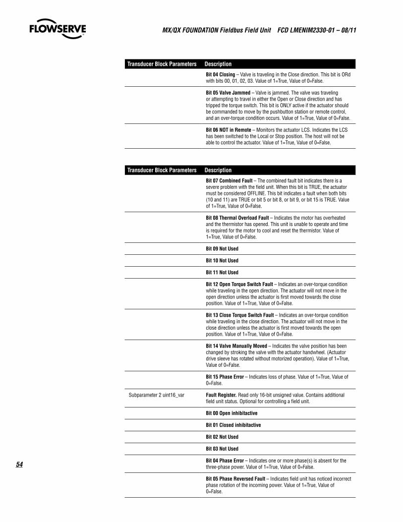
MX/QX FOUNdaTION Fieldbus Field Unit FCd LMENIM2330-01 – 08/11
54
TransducerBlockParameters Description
Bit04Closing – Valve is traveling in the Close direction. This bit is ORd with bits 00, 01, 02, 03. Value of 1=True, Value of 0=False.
Bit05ValveJammed – Valve is jammed. The valve was traveling or attempting to travel in either the Open or Close direction and has tripped the torque switch. This bit is ONLY active if the actuator should be commanded to move by the pushbutton station or remote control, and an over-torque condition occurs. Value of 1=True, Value of 0=False.
Bit06NOTinRemote – Monitors the actuator LCS. Indicates the LCS has been switched to the Local or Stop position. The host will not be able to control the actuator. Value of 1=True, Value of 0=False.
TransducerBlockParameters Description
Bit07CombinedFault – The combined fault bit indicates there is a severe problem with the field unit. When this bit is TRUE, the actuator must be considered OFFLINE. This bit indicates a fault when both bits (10 and 11) are TRUE or bit 5 or bit 8, or bit 9, or bit 15 is TRUE. Value of 1=True, Value of 0=False.
Bit08ThermalOverloadFault – Indicates the motor has overheated and the thermistor has opened. This unit is unable to operate and time is required for the motor to cool and reset the thermistor. Value of 1=True, Value of 0=False.
Bit09NotUsed
Bit10NotUsed
Bit11NotUsed
Bit12OpenTorqueSwitchFault – Indicates an over-torque condition while traveling in the open direction. The actuator will not move in the open direction unless the actuator is first moved towards the close position. Value of 1=True, Value of 0=False.
Bit13CloseTorqueSwitchFault – Indicates an over-torque condition while traveling in the close direction. The actuator will not move in the close direction unless the actuator is first moved towards the open position. Value of 1=True, Value of 0=False.
Bit14ValveManuallyMoved – Indicates the valve position has been changed by stroking the valve with the actuator handwheel. (Actuator drive sleeve has rotated without motorized operation). Value of 1=True, Value of 0=False.
Bit15PhaseError– Indicates loss of phase. Value of 1=True, Value of 0=False.
Subparameter 2 uint16_var FaultRegister. Read only 16-bit unsigned value. Contains additional field unit status. Optional for controlling a field unit.
Bit00Openinhibitactive
Bit01Closedinhibitactive
Bit02NotUsed
Bit03NotUsed
Bit04PhaseError – Indicates one or more phase(s) is absent for the three-phase power. Value of 1=True, Value of 0=False.
Bit05PhaseReversedFault – Indicates field unit has noticed incorrect phase rotation of the incoming power. Value of 1=True, Value of 0=False.

55
MX/QX FOUNdaTION Fieldbus Field Unit FCd LMENIM2330-01 – 08/11
flowserve.com
TransducerBlockParameters Description
Bit04Closing – Valve is traveling in the Close direction. This bit is ORd with bits 00, 01, 02, 03. Value of 1=True, Value of 0=False.
Bit05ValveJammed – Valve is jammed. The valve was traveling or attempting to travel in either the Open or Close direction and has tripped the torque switch. This bit is ONLY active if the actuator should be commanded to move by the pushbutton station or remote control, and an over-torque condition occurs. Value of 1=True, Value of 0=False.
Bit06NOTinRemote – Monitors the actuator LCS. Indicates the LCS has been switched to the Local or Stop position. The host will not be able to control the actuator. Value of 1=True, Value of 0=False.
TransducerBlockParameters Description
Bit06ESDConflict
Bit07InhibitConflict
Bit08CSEinlocal/stop.InputmustbesetforCSEandenabled.
Bit09StopSelected – Monitors the actual Local Control Station (LSC). Indicates the LCS has been switched to the Stop position. The Host and local control station do not have control of the actuator. Value of 1=True, Value of 0= False
Bit10NetworkESDisON – Indicates field unit has been issued a network ESD command. The field unit will command the actuator to operate to the preconfigured position (Open, Close, Stop, Ignore). The network ESD command must be terminated to reset this bit. Value of 1=True, Value of 0=False.
Bit11LocalESDisON– Indicates field unit has been issued a local ESD command. The field unit will command the actuator to operate to the preconfigured position (Open, Close, Stop, Ignore). The local ESD command must be terminated to reset this bit. Value of 1=True, Value of 0=False.
Bit12UnitResetSinceLastPoll– Indicates field unit has reset since the last network poll. This bit is latched until read by the host controller. Value of 1=True, Value of 0=False.
Bit13LocalorStopSelected– Monitors the actual Local Control Station (LSC). Indicates the LCS has been switched to the Local or Stop position. The Host and local control station do not have control of the actuator. Value of 1=True, Value of 0=False.
Bit14OpeninginLocalMode– Monitors the actuator LCS Open switch. Indicates the actuator LCS has been switched to the Local position AND the actuator is being opened from the LCS. The host does not have control of the actuator. Value of 1=True, Value of 0=False.
Bit15ClosinginLocalMode– Monitors the actuator LCS Close switch. Indicates the actuator LCS has been switched to the Local position AND the actuator is being closed from the LCS. The host does not have control of the actuator. Value of 1=True, Value of 0=False.
Subparameter 3 uint16_var AdditionalStatus. Digital Outputs register. read only 16-bit unsigned value. Contains additional field unit status. Optional for controlling a field unit.
Bit00Close– Indicates the field unit close contactor is engaged and the valve is moving in the close direction. This bit is ORd with Bit 01 in this register. Value of 1=True, Value of 0=False.
Bit01Open– Indicates the field unit open contactor is engaged and the valve is moving in the open direction. This bit is ORd with Bit 00 in this register. Value of 1=True, Value of 0=False.
Bit02UserOutputS1orR1(optional)– Indicates the field unit AS-1 Relay has been energized. This relay is configurable to operate under many conditions including FF control. Verify current configuration using the LCS. This is a latched digital output, referenced as terminal points 1 and 2.
Bit03UserOutputS2orR2(optional)– Indicates the field unit AS-2 Relay has been energized. This relay is configurable to operate under many conditions including FF control. Verify current configuration using the LCS. This is a latched digital output, referenced as terminal points 3 and 4.

MX/QX FOUNdaTION Fieldbus Field Unit FCd LMENIM2330-01 – 08/11
56
TransducerBlockParameters Description
Bit04UserOutputR3(optional)– Indicates the field unit AS-3 Relay has been energized. This relay is configurable to operate under many conditions including FF control. Verify current configuration using the LCS. This is a latched digital output, referenced as terminal points 31 and 32.
Bit05UserOutputR4(optional)– Indicates the field unit AS-4 Relay has been energized. This relay is configurable to operate under many conditions including FF control. Verify current configuration using the LCS. This is a latched digital output, referenced as terminal points 42 and 43.
Bit06UserOutputR5(optional)– Optional I/O board required. Indicates the optional field unit AR-1 Relay has been energized. This relay is configurable to operate under many conditions including FF control. Verify current configuration using the LCS. This is a non-latching digital output, referenced as terminal points 35 and 36.
Bit07UserOutputR6(optional)– Optional I/O board required. Indicates the optional field unit AR-2 Relay has been energized. This relay is configurable to operate under many conditions including FF control. Verify current configuration using the LCS. This is a non-latching digital output, referenced as terminal points 44 and 34.
Bit08UserOutputR7(optional)– Optional I/O board required. Indicates the optional field unit AR-3 Relay has been energized. This relay is configurable to operate under many conditions including FF control. Verify current configuration using the LCS. This is a non-latching digital output, referenced as terminal points 33 and 20.
Bit09NetworkBypassRelay– Indicates the network bypass relay is energized. Should this relay be de-energized, the actuator will fail to communicate with the host. Value of 1=True, Value of 0=False.
Bit10R8
Bit11NotUsed
Bits12-15MOVSeries(MX=1,MXa=9,QX=6,QXm=B)
Subparameter 4 uint16_var DigitalInput_1– Read only 16-bit unsigned value. Contains field unit status and digital input status.
Bit00RemoteSelected– Monitors the actual LCS. Indicates the LCS has been switched to the Remote position. The host is in control of the actuator. Value of 1=True, Value of 0=False.
Bit01ThermalOverloadfault– Indicates the motor has overheated and the thermistor has opened. This unit is unable to operate and time is required for the motor to cool and reset the thermistor. Value of 1=True, Value of 0=False.
Bit02OpenTorqueSwitch– Indicates an overtorque condition while traveling in the open direction. This condition will also be true if the actuator is 100% open and torque seated. Value of 1=True, Value of 0=False.
Bit03OpenLimitSwitch– Open limit switch is engaged. Valve is fully opened. Value of 1=True, Value of 0=False.
Bit04CloseTorqueSwitch– Indicates an overtorque condition while traveling in the close direction. This condition will also be true if the actuator is 0% open and torque seated. Value of 1=True, Value of 0=False.
Bit05CloseLimitSwitch– Close limit switch is engaged. Valve is fully closed. Value of 1=True, Value of 0=False.
Bit06NotUsed

57
MX/QX FOUNdaTION Fieldbus Field Unit FCd LMENIM2330-01 – 08/11
flowserve.com
TransducerBlockParameters Description
Bit07NotUsed
Bit08UserInputO/default=ESDInput– User Input 0. Referenced as Terminal 30. Connect with 120 VAC or 24 VDC. Minimum ON voltage 19.2 VAC/DC; maximum OFF voltage 5 VAC/DC. Value of 1=True/ON, Value of 0=False/OFF. Emergency shutdown input. ESD must be configured for OFF to use as a basic user input.
Bit09UserInput1/default=OpenInhibitInput– User Input 1. Referenced as Terminal 34. Connect with 120 VAC or 24 VDC. Minimum ON voltage 19.2 VAC/DC; maximum OFF voltage 5 VAC/DC. Value of 1=True/ON, Value of 0=False/OFF. Open inhibit input. Open inhibit must be configured for OFF to use as a basic user input.
Bit10UserInput2/default=CloseInhibitInput – User Input 2. Referenced as Terminal 35. Connect with 120 VAC or 24 VDC. Minimum ON voltage 19.2 VAC/DC; maximum OFF voltage 5 VAC/DC. Value of 1=True/ON, Value of 0=False/OFF. Close inhibit input. Close inhibit must be configured for OFF to use as a basic user input.
Bit113/RemoteStopInput– User Input 3. Referenced as Terminal 26. Connect with 120 VAC or 24 VDC. Minimum ON voltage 19.2 VAC/DC; maximum OFF voltage 5 VAC/DC. Value of 1=True/ON, Value of 0=False/OFF. Remote stop input. Remote Control must be configured for OFF to use as a basic user input.
Bit124/RemoteOpenInput– User Input 4. Referenced as Terminal 25. Connect with 120 VAC or 24 VDC. Minimum ON voltage 19.2 VAC/DC; maximum OFF voltage 5 V AC/DC. Value of 1=True/ON, Value of 0=False/OFF. Remote open input. Remote Control must be configured for OFF to use as a basic user input.
Bit13UserInput5/RemoteCloseInput– User Input 5. Referenced as Terminal 27. Connect with 120 VAC or 24 VDC. Minimum ON voltage 19.2 VAC/DC; maximum OFF voltage 5 VAC/DC. Value of 1=True/ON, Value of 0=False/OFF. Remote close input. Remote Control must be configured for OFF to use as a basic user input.
Subparameter 5 uint16_var DigitalInput_2. read only 16-bit unsigned value. Contains field unit status and digital input status.
Bit00AnalogBoard1Present
Bit01AnalogBoard2Present
Bit02AnalogInput1Lost– Indicates analog Input 1 is not receiving a 4-20 mA signal. Referenced as terminals 39 and 28 (common). Value of 1=True, Value of 0=False.
Bit03AnalogInput2Lost– Indicates analog Input 2 is not receiving a 4-20 mA signal. Referenced as terminals 40 and 28 (common). Value of 1=True, Value of 0=False.
Bit04Undefined
Bit05NotUsed
Bit06DDCBoardPresent – Indicates presence of optional MX/QX DDC board. This board allows the actuator to be configured for use on the Fieldbus network. Value of 1=True, Value of 0=False.
Bit07I/OOptionalBoardPresent– Indicates presence of optional I/O board. This board provides AR-1 to AR-3 Relays and User Inputs 6-8. This board also contains the 4-20 mA outputs for analog position transmitter (APT) and analog torque transmitter (ATT). Value of 1=True, Value of 0=False.
Bit08FFBoardPresent

MX/QX FOUNdaTION Fieldbus Field Unit FCd LMENIM2330-01 – 08/11
58
TransducerBlockParameters Description
Bit09PBPABoardPresent
Bit10CSEChosenforInput
Bit11DeviceNetBoardPresent
Bit12PhaseLost – Indicates field unit has noticed a phase(s) is absent for the three-phase power. Value of 1=True, Value of 0=False.
Bit13PhaseReverse – Indicates field unit has noticed a 3-phase rotation is incorrect. The field unit will operate the actuator in the proper direction to prevent damage to the valve. Value of 1=True, Value of 0=False.
Bit14NotUsed
BitPBDPBoardPresent
TQ_STATUS Torque Information. Details are given for the Reference and the Last torque, expressed as reference percentages of the rated torque (stated on the nameplate) that occurred at Breakout, Ending, and Peak Running for both the opening and closing directions. Torque will be expressed proportionally as a reference only from 40-100% inclusive. Initial indication may read 0% until torque exceeds 40% minimum.
Subparameter 0 uint16_var
Unused.
Subparameter 1 uint16_var
Average Last Close torque.
Subparameter 2 uint16_var
Average Last Open torque.
Subparameter 3 uint16_var
Last Peak Opening torque.
Subparameter 4 uint16_var
Last Breakout Open torque - the last starting value.to open torque
Subparameter 5 uint16_var
Last Breakout Close torque - the last starting to close torque value.
Subparameter 6 uint16_var
Last Ending Open torque - the last torque value during opening.
Subparameter 7 uint16_var
Peak Ref. Open torque - the peak reference opening torque value, a saved value.
Subparameter 8 uint16_var
Peak Open torque - the peak torque when opening.
Subparameter 9 uint16_var
Last Ending Close - the last torque value when going closed.
Subparameter 10 uint16_var
Breakout Ref. Open torque - the reference starting to open torque value, a saved value.
Subparameter 11 uint16_var
Breakout Ref. Close torque - the reference starting to close torque value, a saved value
Subparameter 12 uint16_var
Ending Ref. Open torque - the reference last torque value during opening, a saved value
Subparameter 13 uint16_var
Update Ending Ref. Close torque - update the reference ending torque value when going closed, a saved value
Subparameter 14 uint16_var
Update Peak Ref. Close torque - update the peak reference closing torque value, a saved value
TP_STATUS Torque Profile Information

59
MX/QX FOUNdaTION Fieldbus Field Unit FCd LMENIM2330-01 – 08/11
flowserve.com
TransducerBlockParameters Description
Subparameter 0 uint16_var
Unused
Subparameter 1 uint16_var
TP_START_POSITION – The position of the actuator when this sampling period began (0 to 100% OPEN)
Subparameter 2 uint16_var
TP_STOP_POSITION – The position of the actuator when this sampling period ended (0 to 100% OPEN)
Subparameter 3 uint16_var
TP_SAMPLE – The number of times that the torque value was sampled for this TP sample. This value is also relative indicator of cycle time and may be trended to identify when actuator performance is changing. Cycle time is approximately equal to “TP Samples” times 50 milliseconds.
Subparameter 4 uint16_var
TP_MID_T_HIGH – The highest relative torque observed in midtravel during this TP sample.
Subparameter 5 uint16_var
TP_MID_T_POS – The position of the actuator (0 to 100% OPEN) when the highest mid-travel torque was observed.
Subparameter 6 uint16_var
TP_MID_T_AV_VAL – The average relative torque observed during this TP sample.
Subparameter 7 uint16_var
TP_STOP_VAL – The relative torque observed at the moment when the valve motion ended, completing this TP sample.
Subparameter 8 uint16_var
TP_BEFORE_MID_T_HIGH – The highest relative torque observed while the actuator is in motion but before the limit switch was cleared indicating that the actuator is in mid-travel. For example, if moving from the CLOSED position, in the OPEN direction, this value represents the highest relative torque value observed before the CLOSED limit switch became inactive.
Subparameter 9 uint16_var
TP_AFTER_MID_T_HIGH – The highest relative torque observed while the actuator is in motion after the limit switch became active indicating that the actuator is no longer in mid-travel. For example, if torque seated and moving from mid-travel, in the CLOSE direction, this value represents the highest relative torque value observed after the closed limit switch became active but before the torque switch stopped movement.
SOFTWARE_VERSION Device software version
FACTORY_DIAGNOSTIC Internal use only
DOWNLOAD_PARAMETER Internal use only
TARGET_ERROR Internal use only
DTM_ARGUMENT DTM specific parameter used in conjunction with DTM_COMMAND_ID parameter for device manufacturer custom operations.
DTM_COMMAND_ID DTM specific parameter used in conjunction with DTM_ARGUMENT parameter for device manufacturer custom operations.
BULK_DATA DTM specific parameter used for device manufacturer custom opera-tions of uploading bulk data to DTM.
HARDWARE_FAULTS The bit enumerated parameter provides hardware fault information such as alarms and warnings. Bit value 1 indicates presence of alarm/warning condition in the actuator.
Bit 00 SPI bus communication
Bit 01 to Bit 09 Not used
Bit 10 Valve jammed

MX/QX FOUNdaTION Fieldbus Field Unit FCd LMENIM2330-01 – 08/11
60
TransducerBlockParameters Description
Bit 11 Over torque
Bit 12 Phase sequence warning
Bit 13 Phase lost
Bit 14 Motor temperature warning
Bit 15 Motor temperature alarm
Bit 14 Motor temperature warning
Bit 15 Motor temperature alarm
Bit 16 Encoder warning
Bit 17 Encoder fault
Bit 18 RAM fault
Bit 19 Flash memory fault
Bit 20 EEPROM fault
Bit 21 Torque sensor fault
Bit 22 Knob fault
Bit 23 LimiGard™ alarm
Bit 24 Contactors fault
Bit 25 Power board fault
Bit 26 Digital output board-2 fault
Bit 27 Digital output board-1 fault
Bit 28 Analog output board-2 fault
Bit 29 Analog output board-1 fault
Bit 30 Fieldbus board-A fault
Bit 31 Not used
NO_OF_ACTIVE_ALARMS Active alarms in the the actuator.
LATEST_ALARM Latest alarm generated in the actuator.
ENCODER_HEALTH The bit enumerated parameter provides the encoder health information. Bit value 1 indicates fault condition
Subparameter0 Provides primary pairs health status of the encoder.
Bit 00 Pair # 102 (D102/Q102) of wheel 0 fault
Bit 01 and Bit 02 Not used
Bit 03 Pair # 103 (D103/Q103) of wheel 1 fault
Bit 04 Pair # 104 (D104/Q104) of wheel 1 fault
Bit 05 Pair # 105 (D105/Q105) of wheel 1 fault
Bit 06 Pair # 106 (D106/Q106) of wheel 2 fault
Bit 07 Pair # 107 (D107/Q107) of wheel 2 fault
Bit 08 Pair # 108 (D108/Q108) of wheel 2 fault

61
MX/QX FOUNdaTION Fieldbus Field Unit FCd LMENIM2330-01 – 08/11
flowserve.com
TransducerBlockParameters Description
Bit 09 Pair # 109 (D109/Q109) of wheel 3 fault
Bit 10 Pair # 110 (D110/Q110) of wheel 3 fault
Bit 11 Pair # 111 (D111/Q111) of wheel 3 fault
Bit 12 Pair # 112 (D112/Q112) of wheel 4 fault
Bit 13 Pair # 113 (D113/Q113) of wheel 4 fault
Bit 14 Pair # 114 (D114/Q114) of wheel 4 fault
Bit 15 Pair # 115 (D115/Q115) of wheel 5 fault
Bit 16 Pair # 116 (D116/Q116) of wheel 5 fault
Bit 17 Pair # 117 (D117/Q117) of wheel 5 fault
Bit 18 Pair # 118 (D118/Q118) of wheel 6 fault
Bit 19 Pair # 119 (D119/Q119) of wheel 6 fault
Bit 20 Pair # 120 (D120/Q120) of wheel 6 fault
Bit 21 Pair # 121 (D121/Q121) of wheel 7 fault
Bit 22 Pair # 122 (D122/Q122) of wheel 7 fault
Bit 23 Pair # 123 (D123/Q123) of wheel 7 fault
Bit 24 Pair # 124 (D124/Q124) of wheel 8 fault
Bit 25 Pair # 125 (D125/Q125) of wheel 8 fault
Bit 26 Pair # 126 (D126/Q126) of wheel 8 fault
Bit 27 Pair # 127 (D127/Q127) of wheel 9 fault
Bit 28 Pair # 128 (D128/Q128) of wheel 9 fault
Bit 29 Pair # 129 (D129/Q129) of wheel 9 fault
Bit 30 and Bit 31 Not used
Subparameter1 Provides redundant pairs health status of the encoder.
Bit 00 Pair # 2 (D2/Q2) of wheel 0 fault
Bit 01 and Bit 02 Not used
Bit 03 Pair # 3 (D3/Q3) of wheel 1 fault
Bit 04 Pair # 4 (D4/Q4) of wheel 1 fault
Bit 05 Pair # 5 (D5/Q5) of wheel 1 fault
Bit 06 Pair # 6 (D6/Q6) of wheel 2 fault
Bit 07 Pair # 7 (D7/Q7) of wheel 2 fault
Bit 08 Pair # 8 (D8/Q8) of wheel 2 fault
Bit 09 Pair # 9 (D9/Q9) of wheel 3 fault
Bit 10 Pair # 10 (D10/Q10) of wheel 3 fault
Bit 11 Pair # 11 (D11/Q11) of wheel 3 fault
Bit 12 Pair # 12 (D12/Q12) of wheel 4 fault
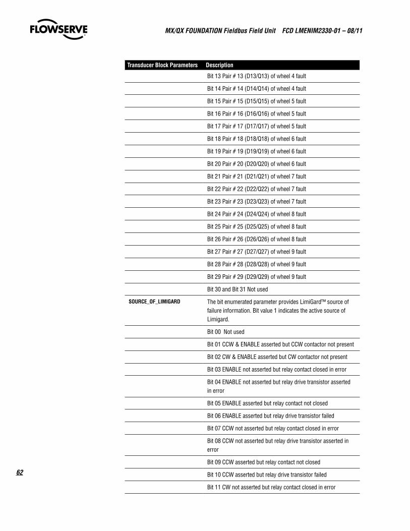
MX/QX FOUNdaTION Fieldbus Field Unit FCd LMENIM2330-01 – 08/11
62
TransducerBlockParameters Description
Bit 13 Pair # 13 (D13/Q13) of wheel 4 fault
Bit 14 Pair # 14 (D14/Q14) of wheel 4 fault
Bit 15 Pair # 15 (D15/Q15) of wheel 5 fault
Bit 16 Pair # 16 (D16/Q16) of wheel 5 fault
Bit 17 Pair # 17 (D17/Q17) of wheel 5 fault
Bit 18 Pair # 18 (D18/Q18) of wheel 6 fault
Bit 19 Pair # 19 (D19/Q19) of wheel 6 fault
Bit 20 Pair # 20 (D20/Q20) of wheel 6 fault
Bit 21 Pair # 21 (D21/Q21) of wheel 7 fault
Bit 22 Pair # 22 (D22/Q22) of wheel 7 fault
Bit 23 Pair # 23 (D23/Q23) of wheel 7 fault
Bit 24 Pair # 24 (D24/Q24) of wheel 8 fault
Bit 25 Pair # 25 (D25/Q25) of wheel 8 fault
Bit 26 Pair # 26 (D26/Q26) of wheel 8 fault
Bit 27 Pair # 27 (D27/Q27) of wheel 9 fault
Bit 28 Pair # 28 (D28/Q28) of wheel 9 fault
Bit 29 Pair # 29 (D29/Q29) of wheel 9 fault
Bit 30 and Bit 31 Not used
SOURCE_OF_LIMIGARD The bit enumerated parameter provides LimiGard™ source of failure information. Bit value 1 indicates the active source of Limigard.
Bit 00 Not used
Bit 01 CCW & ENABLE asserted but CCW contactor not present
Bit 02 CW & ENABLE asserted but CW contactor not present
Bit 03 ENABLE not asserted but relay contact closed in error
Bit 04 ENABLE not asserted but relay drive transistor asserted in error
Bit 05 ENABLE asserted but relay contact not closed
Bit 06 ENABLE asserted but relay drive transistor failed
Bit 07 CCW not asserted but relay contact closed in error
Bit 08 CCW not asserted but relay drive transistor asserted in error
Bit 09 CCW asserted but relay contact not closed
Bit 10 CCW asserted but relay drive transistor failed
Bit 11 CW not asserted but relay contact closed in error

63
MX/QX FOUNdaTION Fieldbus Field Unit FCd LMENIM2330-01 – 08/11
flowserve.com
TransducerBlockParameters Description
Bit 12 CW not asserted but relay drive transistor asserted in error
Bit 13 CW asserted but relay contact not closed
Bit 14 CW asserted but relay drive transistor failed
Bit 15 Stuck relay contacts
COMM_LOSS The User configurable action of the actuator when network communication is interrupted
SubparameterACTION The user configurable action that actuator should take when network communication is interrupted. Value 1=None, 2=Stop, 4=Close, 8=Open and 16=Position.
SubparameterTARGET_POSITION
User configurable target position to which the actuator should move the valve when network communication is interrupted.
SubparameterDELAY User configurable amount of time delay (0-60 seconds) before communication loss is flagged.
ESD Emergency shutdown signal may be applied to the actuator to move the valve to a predetermined user-configured shutdown position, overriding existing control signals.
SubparameterOVERRIDE_SETTINGS
Override settings for ESD.
Bit 00 to Bit 06 Not used
Bit 07 Network ESD - Value 1=ESD overrides network ESD, 0=Network ESD overrides ESD
Bit 08 Two speed - Value 1=ESD overrides two speed, 0=Two speed overrides ESD
Bit 09 Thermostat - Value 1=ESD overrides thermostat, 0=Thermostat overrides ESD
Bit 10 Over torque - Value 1=ESD overrides over torque, 0=Over torque overrides ESD
Bit 11 Lost phase - Value 1=ESD overrides lost phase, 0=Lost phase overrides ESD
Bit 12 Jam - Value 1=ESD overrides jam, 0=Jam overrides ESD
Bit 13 Stop - Value 1=ESD overrides stop, 0=stop overrides ESD
Bit 14 Local command - value 1=ESD overrides local command, 0=Local command overrides ESD
Bit 15 Inhibit - Value 1=ESD overrides inhibit, 0=Inhibit over-rides ESD
SubparameterACTION Predetermined user-configured emergency shutdown action. Value 1=Ignore, 2=Stop, 4=Close, 8=Open and 16=Position.

MX/QX FOUNdaTION Fieldbus Field Unit FCd LMENIM2330-01 – 08/11
64
TransducerBlockParameters Description
SubparameterPOSITION Predetermined user-configured emergency shutdown target position. Range 0 to 100%.
SubparameterACTIVE_SIGNAL Active emergency shutdown signal. Value 1=Network ESD, 2=Local ESD and 3=Both ESD.
PST Record supports implementation of partial stroke test for the device.
SubparameterCOMMAND This parameter is used to pass the PST commands to the device. Value 1=Start PST and 2=Stop PST.
SubparameterTARGET_POSITION
PST target position value scaled to 100. Range 0 to 1000.
SubparameterSTATUS PST staus, value 0=Not started, 1=In progress, 2=Completed, 4=Stopped.
SubparameterRESULT PST result, value 0=Not started, 1=Awaited, 2=Passed, 4=Failed.
SubparameterMAXIMUM_TORQUE
Maximum torque recorded during PST execution, value range 0 to 100%.
TORQUE Record provides support for actuator torque configuration.
SubparameterCLOSE_SETTING The torque limits in the close direction are configured from 40 to 100% of the rated torque in the increments of 1%.
SubparameterOPEN_SETTING The torque limits in the open direction are configured from 40 to 100% of the rated torque in the increments of 1%.
SubparameterBOOST Torque boost is to prevent torque trip during initial valve unseating and in cold climates. Value 1=On, 2=Off and 4=Auto.
SubparameterOUTPUT Torque sensor derives output from motor speed, temperature and voltage. Range: 0 to 100%.
ACT_TYPE Actuator type. Value 16=MX, 96=QX, 144=MXa, 160=UEX and 176=QXM.
ACT_SERIAL_NUMBER Actuator serial number.
QA_STAMP QA stamp.
CONTROL_MODE The actuator can be configured for continuous position control or Open/Close operations.
SubparameterTARGET In Position control mode, the actuator moves the valve to the setpoint value. In Open/Close control mode, the actuator moves the valve to 100% position if setpoint is greater than or equal to 50% and moves to 0% if setpoint is less than 50%. Value 1=Close/open and 2=Position.
SubparameterACTUAL Actual control mode in which actuator is functioning. Value 1=Close/open and 2=Position.
DTM_HEART_BEAT DTM writes hear beat every 30 seconds. The actuator moves the DTM_OPERATION to DTM_READ_ONLY if it does not receive hear beat for 120 second.

65
MX/QX FOUNdaTION Fieldbus Field Unit FCd LMENIM2330-01 – 08/11
flowserve.com
TransducerBlockParameters Description
DTM_OPERATION DTM operation can be set from the DCS/ Configurators to DTM_READ_ONLY or DTM_READ_WRITE. In DTM_READ_WRITE mode the actuator does not respond to commands from DCS/Configurators.
REMOTE_INPUT_MODE The actuator can be placed in various modes. Multi Control mode: This mode allows analog, digital and network control modes of operation to the actuator. Digital Control: The unit will operate only upon the last digital input command received. Network Control: The unit will operate only upon the last network command received. Analog Control: The unit will operate only upon the last analog input command received.
NETWORK_SETPOINT_MODE User selectable network setpoint mode from DCS/DTM/Configurators. REMOTE_DTM mode is effective only when DTM_OPERATION is in DTM_READ_WRITE.
PROPORTIONAL_BAND Proportional band is the range of errors between position and demand signal that will produce reduced speed. Range: 10 to 1000. Increment: 10. Scaled to 100.
DEADBAND The deadband should be wide enough to prevent hunting of the actuator but as low as possible to give adequate response to changes in the error signal. Range: 10 to 500. Increment: 10. Scaled to 100.
ANALOG_SCALING Analog scaling allows the user to change the signal range from the default range.
ACT_OPT_HARDWARES Optional electronics connected to the actuator.
Bit 00 and Bit 01 Not used
Bit 02 Digital output board-2
Bit 03 Digital output board-1
Bit 04 Analog output board-2
Bit 05 Analog output board-1
Bit 06 Fieldbus network board-B
Bit 07 Fieldbus network board-A
ANALOG_1_OUTPUT Record provides support for configuration of analog-1 output board.
SubparameterSTATUS On/off status of the analog-1 output board. Value 1=On and 2=Off.
SubparameterFUNCTION Analog-1 output function configuration. Value 1=APT and 2=ATT.
SubparameterOFFSET Analog-1 output type, value and range configuration. Value 1=4-20mA, 2=0-20mA, 4=1-5V, 8=0-5V, 16=2-10V and 32=0-10V.

MX/QX FOUNdaTION Fieldbus Field Unit FCd LMENIM2330-01 – 08/11
66
TransducerBlockParameters Description
SubparameterPOLARITY Analog-1 output polarity configuration. Value 1=High value at open/max and 2=High value at close/min.
SubparameterATT_SCALE ATT scaling when analog-1 output function configured as ATT.
SubparameterVALUE Analog-1 output value. Range: 0 to 100%.
ANALOG_2_OUTPUT Record provides support for configuration of analog-2 output board.
SubparameterSTATUS On/off status of the analog-2 output board. Value 1=On and 2=Off.
SubparameterFUNCTION Analog-2 output function configuration. Value 1=APT and 2=ATT.
SubparameterOFFSET Analog-2 output type, value and range configuration. Value 1=4-20mA, 2=0-20mA, 4=1-5V, 8=0-5V, 16=2-10V and 32=0-10V.
SubparameterPOLARITY Analog-2 output polarity configuration. Value 1=High value at open/max and 2=High value at close/min.
SubparameterATT_SCALE ATT scaling when analog-2 output function configured as ATT.
SubparameterVALUE Analog-2 output value. Range: 0 to 100%.
STD_DIGITAL_OUTPUT_RELAYS Configuration for R1, R2, R3 and R4 relays on standard digital output relay board.
SubparameterENABLED Digital output relays enabled status. Value 0=Disabled and 1=Enabled.
SubparameterSTATUS Contact operation status.
Bit 00 to Bit 02 Not used
Bit 03 RM contact status
Bit 04 R4 contacts status
Bit 05 R3 contacts status
Bit 06 R2 contacts status
Bit 07 R1 contacts status
SubparameterR1_FUNCTION Function assigned to the relay.
SubparameterR1_CONTACT_TYPE
User configurable realy contact type. Value 1=Close, 2=Open and 4=Blinker.
SubparameterR1_POSITION The relay gets energized when the actuator moves the valve to this user configurable position.
SubparameterR2_FUNCTION Function assigned to the relay.
SubparameterR2_CONTACT_TYPE
User configurable realy contact type. Value 1=Close, 2=Open and 4=Blinker.
SubparameterR2_POSITION The relay gets energized when the actuator moves the valve to this user configurable position.
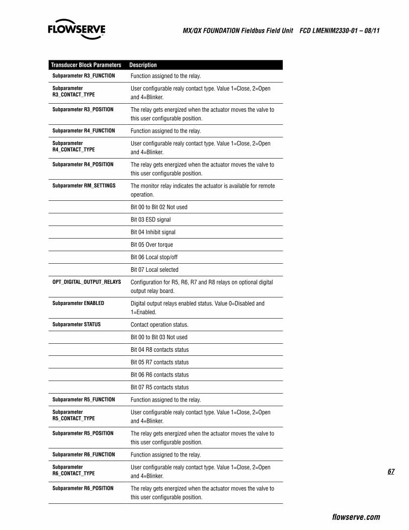
67
MX/QX FOUNdaTION Fieldbus Field Unit FCd LMENIM2330-01 – 08/11
flowserve.com
TransducerBlockParameters Description
SubparameterR3_FUNCTION Function assigned to the relay.
SubparameterR3_CONTACT_TYPE
User configurable realy contact type. Value 1=Close, 2=Open and 4=Blinker.
SubparameterR3_POSITION The relay gets energized when the actuator moves the valve to this user configurable position.
SubparameterR4_FUNCTION Function assigned to the relay.
SubparameterR4_CONTACT_TYPE
User configurable realy contact type. Value 1=Close, 2=Open and 4=Blinker.
SubparameterR4_POSITION The relay gets energized when the actuator moves the valve to this user configurable position.
SubparameterRM_SETTINGS The monitor relay indicates the actuator is available for remote operation.
Bit 00 to Bit 02 Not used
Bit 03 ESD signal
Bit 04 Inhibit signal
Bit 05 Over torque
Bit 06 Local stop/off
Bit 07 Local selected
OPT_DIGITAL_OUTPUT_RELAYS Configuration for R5, R6, R7 and R8 relays on optional digital output relay board.
SubparameterENABLED Digital output relays enabled status. Value 0=Disabled and 1=Enabled.
SubparameterSTATUS Contact operation status.
Bit 00 to Bit 03 Not used
Bit 04 R8 contacts status
Bit 05 R7 contacts status
Bit 06 R6 contacts status
Bit 07 R5 contacts status
SubparameterR5_FUNCTION Function assigned to the relay.
SubparameterR5_CONTACT_TYPE
User configurable realy contact type. Value 1=Close, 2=Open and 4=Blinker.
SubparameterR5_POSITION The relay gets energized when the actuator moves the valve to this user configurable position.
SubparameterR6_FUNCTION Function assigned to the relay.
SubparameterR6_CONTACT_TYPE
User configurable realy contact type. Value 1=Close, 2=Open and 4=Blinker.
SubparameterR6_POSITION The relay gets energized when the actuator moves the valve to this user configurable position.

MX/QX FOUNdaTION Fieldbus Field Unit FCd LMENIM2330-01 – 08/11
68
TransducerBlockParameters Description
SubparameterR7_FUNCTION Function assigned to the relay.
SubparameterR7_CONTACT_TYPE
User configurable realy contact type. Value 1=Close, 2=Open and 4=Blinker.
SubparameterR7_POSITION The relay gets energized when the actuator moves the valve to this user configurable position.
SubparameterR8_FUNCTION Function assigned to the relay.
SubparameterR8_CONTACT_TYPE
User configurable realy contact type. Value 1=Close, 2=Open and 4=Blinker.
SubparameterR8_POSITION The relay gets energized when the actuator moves the valve to this user configurable position.
ACT_OPT_FEATURES Software features that are enabled.
Bit 00 to Bit 05 Not used
Bit 06 Arctic
Bit 07 Two speed timer
TST_CLOSE Record provides support for configuration of close two speed timer.
SubparameterSTATUS On/off status of close two speed timer. Value 1=On and 2=Off.
SubparameterSTART_POSITION Close two speed timer start position. Range 1 to 1000.
SubparameterSTOP_POSITION Close two speed timer stop position. Range 0 to 999.
SubparameterON_TIME Close two speed timer on time. Range: 1 to 20sec. Increment: 0.5sec.
SubparameterOFF_TIME Close two speed timer off time. Range: 1 to 200sec. Increment: 1sec.
TST_OPEN Record provides support for configuration of open two speed timer.
SubparameterSTATUS On/off status of open two speed timer. Value 1=On and 2=Off.
SubparameterSTART_POSITION Open two speed timer start position. Range 0 to 999.
SubparameterSTOP_POSITION Open two speed timer stop position. Range 1 to 1000.
SubparameterON_TIME Open two speed timer on time. Range: 1 to 20sec. Increment: 0.5sec.
SubparameterOFF_TIME Open two speed timer off time. 1 to 200sec. Increment: 1sec.
DIAG_DATA Cumulative device diagnostic data.
ACT_SERVICE_TIME The cumulative service time of the actuator.
COUNTERS Record provides support for monitoring all the operation log counters.
SubparameterMOTOR_RUN_TIME
Total motor operation time in seconds.

69
MX/QX FOUNdaTION Fieldbus Field Unit FCd LMENIM2330-01 – 08/11
flowserve.com
TransducerBlockParameters Description
SubparameterMANUAL_OPERATIONS
Total number of times unit has been manually operated.
SubparameterCLOSE_CONTACTOR_OPERATIONS
Total number of close contactor operations.
SubparameterOPEN_CONTACTOR_OPERATIONS
Total number of open contactor operations.
SubparameterCLOSE_CYCLES Total number of close cycles count.
SubparameterOPEN_CYCLES Total number of open cycles count.
SubparameterDRIVE_SLEEVE_TURNS
Total number of drive sleeve revolutions.
SubparameterSTROKE_TIME Length of time of last actuator operation.
DEVIATION Float value to display the deviation between setpoint and present value. Range: 0 to 100%.
POWER_SUPPLY Record provides support for monitoring the supply voltage and frequency.
SubparameterVOLTAGE Supply voltage.
SubparameterFREQUENCY Supply frequency.
COMPARTMENT_TEMPERATURE Record provides support for monitoring the device compart-ment temperature.
SubparameterVALUE Device compartment temperature value, unit as specified by the UNIT subparameter.
SubparameterUNIT Unit for the device compartment temperature value, 1=Centigrade, 2=Fahrenheit and 4=Kelvin.
MOTOR_TEMPERATURE Record provides support for monitoring the motor temperature.
SubparameterVALUE Motor temperature value, unit as specified by the UNIT subparameter.
SubparameterUNIT Unit for the motor temperature value, 1=Centigrade, 2=Fahrenheit and 4=Kelvin.
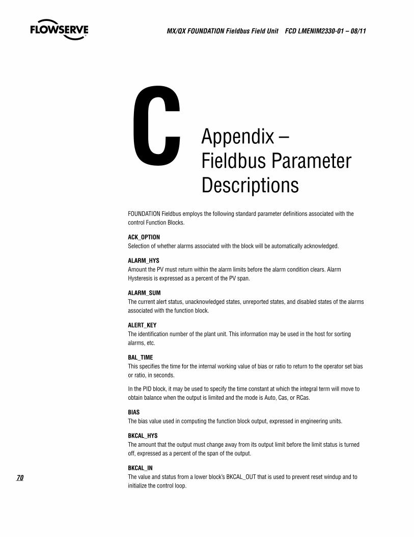
MX/QX FOUNdaTION Fieldbus Field Unit FCd LMENIM2330-01 – 08/11
70
C Appendix – Fieldbus Parameter Descriptions
FOUNDATION Fieldbus employs the following standard parameter definitions associated with the control Function Blocks.
ACK_OPTIONSelection of whether alarms associated with the block will be automatically acknowledged.
ALARM_HYSAmount the PV must return within the alarm limits before the alarm condition clears. Alarm Hysteresis is expressed as a percent of the PV span.
ALARM_SUMThe current alert status, unacknowledged states, unreported states, and disabled states of the alarms associated with the function block.
ALERT_KEYThe identification number of the plant unit. This information may be used in the host for sorting alarms, etc.
BAL_TIMEThis specifies the time for the internal working value of bias or ratio to return to the operator set bias or ratio, in seconds.
In the PID block, it may be used to specify the time constant at which the integral term will move to obtain balance when the output is limited and the mode is Auto, Cas, or RCas.
BIASThe bias value used in computing the function block output, expressed in engineering units.
BKCAL_HYSThe amount that the output must change away from its output limit before the limit status is turned off, expressed as a percent of the span of the output.
BKCAL_INThe value and status from a lower block’s BKCAL_OUT that is used to prevent reset windup and to initialize the control loop.

71
MX/QX FOUNdaTION Fieldbus Field Unit FCd LMENIM2330-01 – 08/11
flowserve.com
BKCAL_OUTThe value and status required by an upper block’s BKCAL_IN so that the upper block may prevent reset windup and provide bumpless transfer to closed loop control.
BKCAL_OUT_DThe output value and status provided to an upstream discrete block. This information is used to provide bumpless transfer to closed loop control.
BKCAL_SEL_1Control elector output value and status associated with SEL_1 input, which is provided to BKCAL_IN of the block connected to SEL_1 in order to prevent reset windup.
BKCAL_SEL_2Control selector output value and status associated with SEL_2 input, which is provided to BKCAL_IN of the block connected to SEL_2 in order to prevent reset windup.
BKCAL_SEL_3Control selector output value and status associated with SEL_3 input, which is provided to BKCAL_IN of the block connected to SEL_3 in order to prevent reset windup.
BLOCK_ALMThe block alarm is used for all configuration, hardware, connection failure or system problems in the block. The cause of the alert is entered in the subcode field. The first alert to become active will set the Active status in the Status attribute. As soon as the unreported status is cleared by the alert reporting task, another block alert may be reported without clearing the Active status, if the subcode has changed.
BLOCK_ERRThis parameter reflects the error status associated with the hardware or software components associated with a block. It is a bit string, so that multiple errors may be shown.
BYPASSThe normal control algorithm may be bypassed through this parameter. When bypass is set, the setpoint value (in percent) will be directly transferred to the output. To prevent a bump on transfer to/from bypass, the setpoint will automatically be initialized to the output value or process variable, respectively, and the path broken flag will be set for one execution.
CAS_INThis parameter is the remote setpoint value, which must come from another Fieldbus block, or a DCS block through a defined link.
CAS_IN_DThis parameter is the remote setpoint value of a discrete block, which must come from another Fieldbus block, or a DCS block through a defined link.
CHANNELThe number of the logical hardware channel that is connected to this I/O block. This information defines the transducer to be used going to or from the physical world.
CLR_FSTATEWriting a Clear to this parameter will clear the device fault state if the field condition, if any, has cleared.

MX/QX FOUNdaTION Fieldbus Field Unit FCd LMENIM2330-01 – 08/11
72
COLLECTION_DIRECTORYA directory that specifies the number, starting indices, and DD Item IDs of the data collections in each transducer within a transducer block. For further information, please refer to the Transducer Block Application Process – Part 1 (FF-902) specification.
CONFIRM_TIMEThe time the resource will wait for confirmation of receipt of a report before trying again. Retry shall not happen when CONFIRM_TIME = 0.
CONTROL_OPTSOptions, which the user may select to alter the calculations done in a control block.
CYCLE_SELUsed to select the block execution method for this resource.
CYCLE_TYPEIdentifies the block execution methods available for this resource.
DD_RESOURCEString identifying the tag of the resource, which contains the Device Description for this resource.
DD_REVRevision of the DD associated with the resource — used by an interface device to locate the DD file for the resource.
DEV_REVManufacturer revision number associated with the resource — used by an interface device to locate the DD file for the resource.
DEV_TYPEManufacturer’s model number associated with the resource — used by interface devices to locate the DD file for the resource.
DISC_ALMThe status and time stamp associated with the discrete alarm.
DISC_LIMState of discrete input, which will generate an alarm.
DISC_PRIPriority of the discrete alarm.
DV_HI_ALMThe status and time stamp associated with the high deviation alarm.
DV_HI_LIMThe setting of the high deviation alarm limit in engineering units.
DV_HI_PRIPriority of the high deviation alarm.
DV_LO_ALMThe status and time stamp associated with the low deviation alarm.
DV_LO_LIMThe setting of the low deviation alarm limit in engineering units.
73
MX/QX FOUNdaTION Fieldbus Field Unit FCd LMENIM2330-01 – 08/11
flowserve.com
DV_LO_PRIPriority of the low deviation alarm.
FAULT_STATECondition set by loss of communication to an output block, fault promoted to an output block or a physical contact. When Fault State condition is set, then output function blocks will perform their FSTATE actions.
FEATURE_SELUsed to select resource block options.
FEATURESUsed to show supported resource block options.
FF_GAINThe gain that the feed forward input is multiplied by before it is added to the calculated control output.
FF_SCALEThe feedforward input high and low scale values, engineering units code, and number of digits to the right of the decimal point.
FF_VALThe feed forward value and status.
FIELD_VALRaw value of the field device in percent of the PV range, with a status reflecting the Transducer condi-tion, before signal characterization (L_TYPE) or filtering (PV_FTIME).
FIELD_VAL_DRaw value of the field device discrete input, with a status reflecting the Transducer condition.
FREE_SPACEPercent of memory available for further configuration. Zero in a preconfigured resource.
FREE_TIMEPercent of the block processing time that is free to process additional blocks.
FSTATE_TIMEThe time in seconds from detection of fault of the output block remote setpoint to the output action of the block output if the condition still exists.
FSTATE_VALThe preset analog SP value to use when fault occurs. This value will be used if the I/O option Fault State to value is selected.
FSTATE_VAL_DThe preset discrete SP_D value to use when fault occurs. This value will be used if the I/O option Fault State to value is selected.
GAINDimensionless value used by the block algorithm in calculating the block output.
GRANT_DENYOptions for controlling access of host computer and local control panels to operating, tuning and alarm parameters of the block.

MX/QX FOUNdaTION Fieldbus Field Unit FCd LMENIM2330-01 – 08/11
74
HARD_TYPESThe types of hardware available as channel numbers.
HI_ALMThe status for high alarm and its associated time stamp.
HI_HI_ALMThe status for high high alarm and its associated time stamp.
HI_HI_LIMThe setting for high high alarm in engineering units.
HI_HI_PRIPriority of the high high alarm.
HI_LIMThe setting for high alarm in engineering units.
HI_PRIPriority of the high alarm.
IO_OPTSOptions, which the user may select to alter input and output block processing.
INThe primary input value of the block, required for blocks that filter the input to get the PV.
IN_1Auxiliary input value to the block, used for other values than the PV.
ITK_VERMajor revision number of the interoperability test case used in certifying this device as interoperable. The format and range of the version number is defined and controlled by the Fieldbus Foundation.
NOTE: The value of this parameter will be zero (o) if the device has not been registered as interoperable by the FF.
LIM_NOTIFYMaximum number of unconfirmed alert notify messages allowed.
L_TYPEDetermines if the values passed by the transducer block to the AI block may be used directly (Direct) or if the value is in different units and must be converted linearly (Indirect), or with square root (Ind Sqr Root), using the input range defined by the transducer and the associated output range.
LO_ALMThe status of the low alarm and its associated time stamp.
LO_LIMThe setting for the low alarm in engineering units.
LO_LO_ALMThe status of the low low alarm and its associated time stamp.
LO_LO_LIMThe setting of the low low alarm in engineering units.
75
MX/QX FOUNdaTION Fieldbus Field Unit FCd LMENIM2330-01 – 08/11
flowserve.com
LO_LO_PRIPriority of the low low alarm.
LO_PRIPriority of the low alarm.
LOW_CUTLimit used in square root processing. A value of zero percent of scale is used in block processing if the transducer value falls below this limit, in % of scale. This feature may be used to eliminate noise near zero for a flow sensor.
MANUFAC_IDManufacturer identification number — used by an interface device to locate the DD file for the resource.
MAX_NOTIFYMaximum number of unconfirmed notify messages possible.
MEMORY_SIZEAvailable configuration memory in the empty resource. To be checked before attempting a download.
MIN_CYCLE_TTime duration of the shortest cycle interval of which the resource is capable.
MODE_BLKThe actual, target, permitted, and normal modes of the block.
NV_CYCLE_TMinimum time interval specified by the manufacturer for writing copies of NV parameters to non-volatile memory. Zero means it will never be automatically copied. At the end of NV_CYCLE_TIME, only those parameters which have changed (as defined by the manufacturer) need to be updated in NVRAM.
OUTThe primary analog value calculated as a result of executing the function.
OUT_DThe primary discrete value calculated as a result of executing the function.
OUT_HI_LIMLimits the maximum output value.
OUT_LO_LIMLimits the minimum output value.
OUT_SCALEThe high and low scale values, engineering units code, and number of digits to the right of the decimal point to be used in displaying the OUT parameter and parameters which have the same scaling as OUT.
OUT_STATEIndex to the text describing the states of a discrete output.
PVEither the primary analog value for use in executing the function, or a process value associated with it. May also be calculated from the READBACK value of an AO block.

MX/QX FOUNdaTION Fieldbus Field Unit FCd LMENIM2330-01 – 08/11
76
PV_DEither the primary discrete value for use in executing the function, or a process value associated with it. May also be calculated from the READBACK_D value of a DO block.
PV_FTIMETime constant of a single exponential filter for the PV, in seconds.
PV_SCALEThe high and low scale values, engineering units code, and number of digits to the right of the decimal point to be used in displaying the PV parameter and parameters which have the same scaling as PV.
PV_STATEIndex to the text describing the states of a discrete PV.
RA_FTIMETime constant of a single exponential filter for the value to be ratioed, in seconds.
RATEDefines the derivative time constant, in seconds.
RCAS_INTarget setpoint and status provided by a supervisory Host to a analog control or output block.
RCAS_IN_DTarget setpoint and status provided by a supervisory Host to a discrete control or output block.
RCAS_OUTBlock setpoint and status after ramping - provided to a supervisory Host for back calculation and to allow action to be taken under limiting conditions or mode change.
RCAS_OUT_DBlock setpoint and status provided to a supervisory Host for back calculation and to allow action to be taken under limiting conditions or mode change.
READBACKThis indicates the readback of the actual continuous valve or other actuator position, in transducer units.
READBACK_DThis indicates the readback of the actual discrete valve or other actuator position, in the transducer state.
RESETThe integral time constant, in seconds per repeat.
RESTARTAllows a manual restart to be initiated. Several degrees of restart are possible. They are 1: Run, 2: Restart resource, 3: Restart with defaults, and 4: Restart processor.
ROUT_INTarget output and status provided by a Host to the control block for use as the output (ROut mode).
ROUT_OUTBlock output and status — provided to a Host for back calculation in ROut mode and to allow action to be taken under limited conditions or mode change.

77
MX/QX FOUNdaTION Fieldbus Field Unit FCd LMENIM2330-01 – 08/11
flowserve.com
RS_STATEState of the function block application state machine.
SEL_1First input value to the selector.
SEL_2Second input value to the selector.
SEL_3Third input value to the selector.
SEL_TYPEThis parameter specifies the type of selector action, from choices of High, Medium, and Low.
SET_FSTATEAllows the Fault State condition to be manually initiated by selecting Set.
SHED_OPTDefines action to be taken on remote control device timeout.
SHED_RCASTime duration at which to give up on computer writes to function block RCas locations. Shed from RCas shall never happen when SHED_RCAS = 0.
SHED_ROUTTime duration at which to give up on computer writes to function block ROut locations. Shed from Rout shall never happen when SHED_ROUT = 0.
SIMULATEAllows the transducer analog input or output to the block to be manually supplied when simulate is enabled. When simulation is disabled, the simulate value and status track the actual value and status.
SIMULATE_DAllows the transducer discrete input or output to the block to be manually supplied when simulate is enabled. When simulation is disabled, the simulate value and status track the actual value and status.
SPThe analog setpoint of this block.
SP_DThe discrete setpoint of this block.
SP_HI_LIMThe setpoint high limit is the highest setpoint operator entry that can be used for the block.
SP_LO_LIMThe setpoint low limit is the lowest setpoint operator entry that can be used for the block.
SP_RATE_DNRamp rate at which downward setpoint changes are acted on in Auto mode, in PV units per second. If the ramp rate is set to zero, then the setpoint will be used immediately. For control blocks, rate limiting will apply only in Auto. For output blocks, rate limiting will apply in Auto, Cas, and RCas modes.

MX/QX FOUNdaTION Fieldbus Field Unit FCd LMENIM2330-01 – 08/11
78
SP_RATE_UPRamp rate at which upward setpoint changes are acted on in Auto mode, in PV units per second. If the ramp rate is set to zero, then the setpoint will be used immediately. For control blocks, rate limiting will apply only in Auto. For output blocks, rate limiting will apply in Auto, Cas, and RCas modes.
ST_REVThe revision level of the static data associated with the function block. To support tracking changes in static parameter attributes, the associated block’s static revision parameter will be incremented each time a static parameter attribute value is changed. Also, the associated block’s static revision parameter may be incremented if a static parameter attribute is written but the value is not changed.
STATUS_OPTSOptions, which the user may select in the block processing of status.
STRATEGYThe strategy field can be used to identify grouping of blocks. This data is not checked or processed by the block.
TAG_DESCThe user description of the intended application of the block.
TEST_RWRead/write test parameter - used only for conformance testing.
TRANSDUCER_DIRECTORYA directory that specifies the number and starting indices of the transducers in the transducer block. For further information, please refer to the Transducer Block Application Process – Part 1 (FF-902) specification.
TRK_IN_DThis discrete input is used to initiate external tracking of the block output to the value specified by TRK_VAL.
TRK_SCALEThe high and low scale values, engineering units code, and number of digits to the right of the decimal point, associated with TRK_VAL.
TRK_VALThis input is used as the track value when external tracking is enabled by TRK_IN_D.
UPDATE_EVTThis alert is generated by any change to the static data.
WRITE_ALMThis alert is generated if the write lock parameter is cleared.
WRITE_LOCKIf set, no writes from anywhere are allowed, except to clear WRITE_LOCK. Block inputs will continue to be updated.
WRITE_PRIPriority of the alarm generated by clearing the write lock.

79
MX/QX FOUNdaTION Fieldbus Field Unit FCd LMENIM2330-01 – 08/11
flowserve.com
XD_SCALEThe high and low scale values, engineering units code, and number of digits to the right of the decimal point used with the value obtained from the transducer for a specified channel.
XD_STATEIndex to the text describing the states of a discrete for the value obtained from the transducer. Writing a Clear to this parameter will clear the device fault state if the field condition, if any, has cleared.

MX/QX FOUNdaTION Fieldbus Field Unit FCd LMENIM2330-01 – 08/11
80
GlossaryCommunicationsProtocol A standard for transferring data between intelligent devices, such as a Master Station, distributed control system, programmable controller, or a computer.
DCS Distributed Control System. Geographically distributed intelligent control devices communi-cating over a digital network (bus).
DeviceDescription Software loaded into the master station that describes the characteristics and parameters of the fieldbus-mounted device.
DeviceTypeManager(DTM) The DTM is a device driver that provides a unified structure for accessing device parameters, configuring and operating the devices, and diagnosing problems. A Device DTM is provided by the device manufacturer and represents the specific logic and parameters of the device. This standardized interface can be used in any FDT Frame Application.
EIA Electronic Industries Association, an organized body of manufacturers that sets interface standards for the electrical and electronic industry, see RS-232C and RS-485.
FieldDeviceToolFrameApplication A software program that implements DeviceDTMs and CommDTMs. The Frame Application provides:1) Common environment 2) User Management 3) DTM Management 4) Data Management 5) Network Configuration 6) Navigation
Foundationfieldbus A standard allowing intelligent field-mounted devices such as valves and transmitters to communicate with each other and with a master station such as a DCS.
FunctionBlocks A standard graphical representation of the control and measurement tasks that take place in the field devices, used for easy system configuration.
Gateway A device in a DDC-100 serial communication system to translate one set of commands to another set of commands that can be understood by other user-supplied devices in the system, for example a Master Station.
LED Light Emitting Diode, a semiconductor diode that emits light when current passes through it, used for various displays in industrial systems and consumer products.
LinkActiveScheduler The fieldbus device responsible for scheduling communication with, and operation of each of the devices on the fieldbus network.
Modem Modulator/demodulator, hardware that converts serial digital bit streams into audio frequency signals when transmitting or modulating data, then changes the audio frequencies back into digital streams when receiving or demodulating data.
MX/QXFF The intelligent Foundation fieldbus board residing in the Limitorque actuator that communicates with the master station and controls actuator.
ParallelDataTransmission The transmission of digital data bits in parallel over several wire Compare to serial data transmission

81
MX/QX FOUNdaTION Fieldbus Field Unit FCd LMENIM2330-01 – 08/11
flowserve.com
ProportionalIntegralDerivativeControlMethodology Control loop feedback algorithm that calculates an “error” value as the difference between a measured “process variable” and a desired “setpoint”. The weighted sum of the three P-I-D actions is used to adjust the process via a control element such as the position of a valve.
PLC Programmable Logic Controller, an intelligent microprocessor-based replacement for relay logic systems, used for process and machinery control applications.
RS-232C An EIA standard for serial data transmission found in almost all personal computers and other serial communication systems not exceeding 30 feet. Recently the EIA has renamed the standard EIA-232.
RS-485 An EIA standard for half duplex, serial data transmission used in multipoint, or parallel, communication systems. This is an excellent choice for long distance serial data read only 16-bit unsigned value. Contains field unit status and digital input status transfer because it includes data rates up to 10 megabytes/second, excellent noise rejection, and the ability to withstand up to +/•7 volts of instantaneous common mode voltage without loss of signal.
RTU Remote Terminal Device, a generic name for an intelligent device remotely located, used for control or data collection purposes.
SerialDataTransmission The transmission of digital data bits sequentially over a transmission medium. Compare to parallel data transmission
TwistedPair A serial digital data communications medium incorporating two wires twisted together to minimize interference from near-by noise sources. Limitorque recommends Belden’s 3076F, or equivalent cable.

MX/QX FOUNdaTION Fieldbus Field Unit FCd LMENIM2330-01 – 08/11
82
This page intentionally left blank.

83
MX/QX FOUNdaTION Fieldbus Field Unit FCd LMENIM2330-01 – 08/11
flowserve.com
This page intentionally left blank.

flowserve.com
To find your local Flowserve representative, visit www.flowserve.com, www.limitorque.com or call USa 1 800 225 6989
Flowserve Corporation has established industry leadership in the design and manufacture of its products. When properly selected, this Flowserve product is designed to perform its intended function safely during its useful life. However, the purchaser or user of Flowserve products should be aware that Flowserve products might be used in numerous applications under a wide variety of industrial service conditions. Although Flowserve can (and often does) provide general guidelines, it cannot provide specific data and warnings for all possible applications. The purchaser/user must therefore assume the ultimate responsibility for the proper sizing and selection, installation, operation, and maintenance of Flowserve products. The purchaser/user should read and understand the Installation Operation Maintenance (IOM) instructions included with the product, and train its employees and contractors in the safe use of Flowserve products in connection with the specific application.
While the information and specifications contained in this literature are believed to be accurate, they are supplied for informative purposes only and should not be considered certified or as a guarantee of satisfactory results by reliance thereon. Nothing contained herein is to be construed as a warranty or guarantee, express or implied, regarding any matter with respect to this product. Because Flowserve is continually improving and upgrading its product design, the specifications, dimensions and information contained herein are subject to change without notice. Should any question arise concerning these provisions, the purchaser/user should contact Flowserve Corporation at any one of its worldwide operations or offices.
© 2011 Flowserve Corporation, Irving, Texas, USA. Flowserve is a registered trademark of Flowserve Corporation.
FCD LMENIM2330-01 – 08/11 Printed in USA.
FlowserveCorporationFlowControl
UnitedStatesFlowserve Limitorque5114 Woodall Road P.O. Box 11318Lynchburg, VA 24506-1318Phone: 434-528-4400Facsimile: 434-845-9736
EnglandFlowserve LimitorqueEuro HouseAbex RoadNewburyBerkshire, RG14 5EYUnited KingdomPhone: 44-1-635-46999Facsimile: 44-1-635-36034
JapanLimitorque – Nippon Gear Co., Ltd.NOF Bldg. 9th Floor1-11-11, Kita-Saiwai, Nishi-KuYokohama (220-0004)JapanPhone: 81-45-326-2065Facsimile: 81-45-320-5962
SingaporeFlowserve Limitorque12, Tuas Avenue 20Singapore 638824Phone: 65-6868-4628Facsimile: 65-6862-4940
ChinaLimitorque Beijing, Pte., Ltd.RM A1/A222/F, East Area, Hanwei PlazaNo. 7 Guanghua Road, Chaoyang DistrictBeijing 100004, Peoples Republic of ChinaPhone: 86-10-5921-0606Facsimile: 86-10-6561-2702
IndiaFlowserve Limitorque, Ltd. Plot No 4 Export Promotional Industrial ParkWhitefield, Bangalore 560066 IndiaPhone: 91-80-40146200Facsimile: 91-80-28410286