user guide small display evaluation kit pldek … revision 4.0 page 3 of 21 contents 1 about plastic...
TRANSCRIPT
PL-CUS-Manual-001944 Revision 4.0
Page 1 of 21
USER GUIDE
Small Display Evaluation Kit
PLDEK_BNE-HBZ6
Part-No. 700912
PL-CUS-Manual-001944 Revision 4.0
Page 2 of 21
Revision
Status Date Editor Reason of Modification
1.0 27/09/13 Initial Version
1.1 04/11/13 Fixed resolution for small displays
2.0 10/04/14 Software update (BN-L6)
3.0 17/04/14 Review
4.0 17/12/14
public release
PL-CUS-Manual-001944 Revision 4.0
Page 3 of 21
Contents
1 About Plastic Logic’s Display Evaluation Kit ............................................................. 5
2 About this document ................................................................................................... 6
3 Glossary of terms / abbreviations ............................................................................... 7
4 Safety Instructions ....................................................................................................... 8
5 Getting Started ............................................................................................................. 9
5.1 Supported Operating Systems ................................................................................ 9
5.2 Unpacking the Kit .................................................................................................... 9
5.3 Connecting the Display with the Kit ........................................................................10
5.4 System Boot and Image Display ............................................................................10
6 Controlling the Kit from a PC .....................................................................................11
6.1 Connecting the Kit to a PC via USB .......................................................................11
6.2 Stopping and Starting the Slideshow ......................................................................12
6.3 Setting the Display Type ........................................................................................13
6.4 Setting Waveform and VCOM ................................................................................12
7 Transferring Files ........................................................................................................14
7.1 Ethernet via USB ....................................................................................................14
7.2 FTP Connection .....................................................................................................15
7.3 Waveform and VCOM Upload ................................................................................15
7.4 Image Upload .........................................................................................................15
7.5 Selecting Slideshows .............................................................................................15
8 Software Overview ......................................................................................................17
8.1 Software Development Kit ......................................................................................17
8.1.1 eptest: e-paper test application .......................................................................17
8.1.2 epview: e-paper document viewer application .................................................17
8.2 Shell Scripts ...........................................................................................................17
8.2.1 slideshow-enable.sh ........................................................................................17
8.2.2 slideshow-disable.sh .......................................................................................18
8.2.3 slideshow-start.sh ...........................................................................................18
8.2.4 slideshow-stop.sh ............................................................................................18
8.2.5 slideshow-run.sh .............................................................................................18
8.2.6 slideshow-select.sh .........................................................................................18
8.2.7 list-override-files.sh .........................................................................................18
8.2.8 set-override.sh ................................................................................................18
8.3 Services .................................................................................................................19
PL-CUS-Manual-001944 Revision 4.0
Page 4 of 21
8.3.1 EPDC: Display driver service ..........................................................................19
8.3.2 EPUI: Slideshow service .................................................................................19
9 Troubleshooting ..........................................................................................................20
10 References ...............................................................................................................21
PL-CUS-Manual-001944 Revision 4.0
Page 5 of 21
1 About Plastic Logic’s Display Evaluation Kit
Plastic Logic’s Display Evaluation Kit (PLDEK, referred to as the “kit”) has been designed to
be used for a range of activities including:
1. Evaluating Plastic Logic’s display technology.
2. Evaluating the appearance of customer and 3rd party content on Plastic Logic
displays.
3. Building expertise with Plastic Logic Display systems prior to designing products or
systems that incorporate our displays.
4. Application development.
PL-CUS-Manual-001944 Revision 4.0
Page 6 of 21
2 About this document
This document is a user guide for the Small Display Evaluation Kit. It is only to be used for
kits containing a BeagleBone [1] and a Hummingbird Z6 board. It is intended to give
sufficient information to:
1. Safely unpack and power up the kit.
2. Start displaying images in png format.
3. Understand how to start using the Plastic Logic Software Development Kit (SDK).
This document refers to the software version BN-L6.

PL-CUS-Manual-001944 Revision 4.0
Page 7 of 21
3 Glossary of terms / abbreviations
COF Chip On Flex. A packaging technology used by Plastic Logic for
packaging source and gate driver chips.
Electrophoretic Display An electrophoretic display typically consists of a layer of small
capsules of fluid which also contains electrically charged dye particles.
When an electric field is applied to the capsules, the dye particles will
tend to move in a direction determined by the sign of the charge.
Display Controller This part of the display system converts a target image which is due to
be displayed into a sequence of sub-frames.
EPDC Electrophoretic Display Controller
MPWB Module Printed Wire Board.
PLDEK Plastic Logic Display Evaluation Kit
SDK Software Development Kit
HVPMIC High Voltage Power Management Integrated Circuit
CPLD Complex Programmable Logic Device
PL-CUS-Manual-001944 Revision 4.0
Page 8 of 21
4 Safety Instructions
Warning:
To avoid risk of electric shock or damage to the display, disconnect the
display module from its power source before handling it.
Do not touch the connections or circuits whilst the display is in operation.
Caution:
Follow ESD handling procedures to avoid circuit damage. Use a grounded wrist
strap.
Consult the document “Handling Instruction Plastic Logic Display Modules” [3]
to prevent electrical or mechanical damage of the display.
Important Notice
The Plastic Logic Display Evaluation Kit (“the kit”) is intended for use for
ENGINEERING DEVELOPMENT, DEMONSTRATION OR EVALUATION PURPOSES
ONLY and is not considered by Plastic Logic to be a finished end-product fit for
general consumer use. Persons handling the kit must have electronics training and
observe good engineering practice standards. As such, the kit being provided is not
intended to be complete in terms of required design-, marketing-, and/or
manufacturing-related protective considerations, including product safety and
environmental measures typically found in end products that incorporate such
semiconductor components or circuit boards. The kit does not fall within the scope of
the European directives regarding electromagnetic compatibility, restricted
substances (RoHS), recycling (WEEE), FCC, CE or UL, and therefore may not meet the
technical requirements of these directives or other related directives.

PL-CUS-Manual-001944 Revision 4.0
Page 9 of 21
5 Getting Started
Prior to unpacking the kit the user is required to take appropriate ESD and safety
precautions!
5.1 Supported Operating Systems
Windows 7 and Windows XP are the supported operating systems to control the kit remotely
via SSH, FTP or a serial connection. All described procedures are based on a Windows 7
system.
5.2 Unpacking the Kit
The kit is shipped with the items listed in the table below. Ensure that the items listed have
been included in your kit. Remove the kit from the anti-static bags and perform a visual
inspection.
No.
No.
Item Description
1 Board 1 BeagleBone Evaluation board
2 Board 2 Hummingbird Z6 board
3 Board 3 Ruddock 2.0 board
4 Flat Cable Cable to connect board 2 and 3
5 Micro - SD Card Contains operating system, slideshow images, display specific
waveforms. The Micro-SD card is mounted in the socket of board 1.
1. 6 Power supply 5.0V/2A power supply with regional adapters
7 USB cable To connect the kit via the mini USB port with a PC
Mini USB Port
Ethernet
Connector
Flat Cable BeagleBone
Board 1
Hummingbird Z6
Board 2
5V Power
Supply
Ruddock 2.0
Board 3
Micro
SD Card
Socket
Display
Connector
PL-CUS-Manual-001944 Revision 4.0
Page 10 of 21
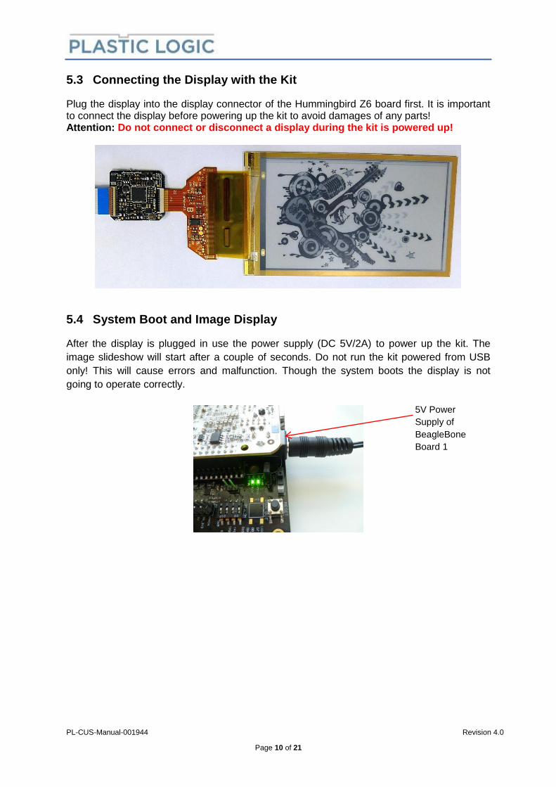
5.3 Connecting the Display with the Kit
Plug the display into the display connector of the Hummingbird Z6 board first. It is important to connect the display before powering up the kit to avoid damages of any parts! Attention: Do not connect or disconnect a display during the kit is powered up!
5.4 System Boot and Image Display
After the display is plugged in use the power supply (DC 5V/2A) to power up the kit. The
image slideshow will start after a couple of seconds. Do not run the kit powered from USB
only! This will cause errors and malfunction. Though the system boots the display is not
going to operate correctly.
5V Power
Supply of
BeagleBone
Board 1

PL-CUS-Manual-001944 Revision 4.0
Page 11 of 21
6 Controlling the Kit from a PC
6.1 Connecting the Kit to a PC via USB
To control the kit remotely it is required to set up a connection. It is recommended to use a
serial connection over USB. Plug in the included USB cable into the PC first. Plug in the
cable into the kit afterwards.
If the connection fails by some reason it is important to remove the mini USB cable from the
kit and reconnect it. Removing the cable from the PC only might not fix the problem.
Execute the following steps to establish the connection:
Click on the Windows “Start” button and select “Devices and Printers”.
Double-Click “BeagleBone…”.
Click the “Hardware” tab.
Find out the COM port of the USB Serial Port.
Use PuTTY [2] to connect the PC to the kit. PuTTY is an open source SSH and telnet
client and can be downloaded from:
www.chiark.greenend.org.uk/~sgtatham/putty/download.html.
Choose connection type “Serial” and configure the COM port and the speed (115200).

PL-CUS-Manual-001944 Revision 4.0
Page 12 of 21
Click “Open” and a terminal window will appear.
Press “ENTER” and the Ångström [3] login screen appears.
Log in using the following credentials: login “root”, password “”.
Now you are successfully logged-in and can use the shell.
6.2 Stopping and Starting the Slideshow
To stop the slideshow use the command slideshow-stop.sh.To start the slideshow use the
command slideshow-start.sh.
6.3 Setting Waveform and VCOM
Displays of some types have an EEPROM fitted that has the waveform and vcom stored.
The kit will use that information to configure itself automatically. If the display EEPROM is not
fitted or not programmed the waveform and vcom has to be set manually.
Nevertheless it is always possible to set the waveform and vcom manually. Stop the
slideshow before updating the waveform and vcom! Each display has a specific waveform
and a vcom which have to be stored as files in the directory /mnt/data/wfl on the kit. The files
are named by the display ID. The command list-override-files.sh lists all these files.
PL-CUS-Manual-001944 Revision 4.0
Page 13 of 21
The command set-override.sh 1 <display-id> will apply the waveform file and the vcom file
including a restart of the epdc driver to enable the new settings. For example:
set-override.sh 1 00076451805800
6.4 Setting the VCOM
If you want to override the vcom only use the following commands.
echo 4000 > /mnt/data/override/voltage/VCOM
/etc/init.d/epdc restart
This example will set the vcom to 4V (4000mV). The epdc driver needs to be restarted to
apply the new settings.
6.5 Setting the Display Type
The kit supports multiple display types. Displays of some types have an EEPROM fitted that
has the display type stored. The kit will use that information to configure itself automatically.
If the display EEPROM is not fitted or not programmed the display type should already be set
according to the displays delivered with the kit. If displays of different types are available it
might be required to set the display type depending on which display is actually connected.
Nevertheless it is always possible to set the display type manually. Stop the slideshow before
setting the display type! Use the command set-override.sh type <Type> to do so. This
includes a restart of the epdc driver to apply the new setting. For example:
set-override.sh type Type18
Consult the Plastic Logic Software Manual [4] to get an overview of the various display
types.

PL-CUS-Manual-001944 Revision 4.0
Page 14 of 21
7 Transferring Files
7.1 Ethernet via USB
If the system is powered up and the slideshow is running connect the kit with the provided
mini USB cable to your PC. Ethernet over USB will be enabled automatically on the kit after
plugging in the USB cable. A USB Ethernet/RNDIS gadget will be installed on the PC
automatically. This device can be found in the “Devices and Printers” dialog.
Now your Ethernet connection is enabled. The kit runs a DHCP server so that it is not required to change the network settings of the RNDIS/Ethernet Gadget on the PC. The kit uses the IP address 192.168.7.2 and the PC uses the IP address 192.168.7.1. Check the “Network and Sharing Center” to verify the network settings on the PC. Use “Change adapter settings” to list all available network connections. Open the local area connection which belongs to the USB Ethernet/RNDIS Gadget. Open “Details” to check the IP address which is actually used. Close the dialog and open “Properties” and then open the “Internet Protocol Version 4” properties. This should have “Obtain an IP address automatically” selected.

PL-CUS-Manual-001944 Revision 4.0
Page 15 of 21
With the Ethernet connection enabled the kit can be accessed via FTP and SSH. The FTP connection does not require a user or a password. The SSH connection uses the same credentials as the serial connection (login “root”, password “”).
7.2 FTP Connection
If your PC is successfully connected to the kit via USB open your Windows Explorer on the
PC (do not use the Internet Explorer) and use the address ftp://192.168.7.2 to open an FTP
connection to the kit. The user data partition should be accessible now. The user data
partition is a FAT partition that is mounted in the root file system of the kit under /mnt/data.
7.3 Waveform and VCOM Upload
Waveform files and vcom files have to be located in the directory /mnt/data/wfl in order to be
applied by the set-override.sh shell script. If the files are not present on the kit they have to
be transferred via FTP to this directory.
7.4 Image Upload
The user data partition can be used to store customer specific images. All default images are
stored in subdirectories of the img directory. The img directory also contains a directory
named customer which is recommended to be used for customer content.
The images have to be of png format. Depending on the type of the display the size of the
images can vary. Typical resolutions for small displays are 400x240 or 320x240. Transfer the
images to the user data partition in preparation for displaying them.
7.5 Selecting Slideshows
If the slideshow is running stop it first and restart it after the selection is done. Use the
following command to select the img/customer directory to be used for the slideshow.
slideshow-select.sh customer
Use the following command to go back to the default slideshow.
slideshow-select.sh default monochrome
PL-CUS-Manual-001944 Revision 4.0
Page 16 of 21
The command to select the slideshow always uses /mnt/data/img as the base directory. A
subdirectory containing the images to be displayed can be specified explicitly by its relative
path (e.g. customer). Alternatively the parameter default can be used. This will cause an
automatic detection of the display resolution based on the currently defined display type. The
relative path to the directory containing the images to be displayed is concatenated as
follows: default_<resolution>, e.g. default_400x320. The second parameter is used to define
a relative path which is appended to the resolution based path, e.g.
default_400x320/monochrome.

PL-CUS-Manual-001944 Revision 4.0
Page 17 of 21
8 Software Overview
8.1 Software Development Kit
The SDK contains several libraries and applications to control an e-paper display and
demonstrate its operation. Check the Plastic Logic Software Manual [4] and the PLSDK
documentation [5], [6] for more detailed information.
8.1.1 eptest: e-paper test application
The eptest application draws test patterns and shows the use of various e-paper features. To
clear the screen and run a basic test pattern use the following command.
eptest -c
Use the help option to get detailed usage information.
eptest --help
8.1.2 epview: e-paper document viewer application
Images can be shown on an e-paper display using epview. Only png format is supported.
The image resolution should match the display resolution, e.g. 400x240 or 320x240.
There are a number of example images on the kit. For small displays use either the images
in the directory /mnt/data/img/default_400x240/monochrome or in the directory
/mnt/data/img/default_320x240/monochrome. These images can be displayed as shown in
the following example:
epview /mnt/data/img/default_400x240/monochrome/01.png
Use the help option to get detailed usage information.
epview --help
8.2 Shell Scripts
The shell scripts are located in the directory /mnt/data/bin. This directory is included in the
“PATH” environment variable. Therefore the scripts can be executed from any location in the
file system without specifying the path they are located in.
8.2.1 slideshow-enable.sh
This script enables the slideshow. That is the slideshow can be started manually respectively
it is started automatically during the boot process.

PL-CUS-Manual-001944 Revision 4.0
Page 18 of 21
8.2.2 slideshow-disable.sh
This script disables the slideshow. That is the slideshow cannot be started manually
respectively it is not started automatically during the boot process.
8.2.3 slideshow-start.sh
This script starts the slideshow so that it runs in the background. It uses the epui service.
8.2.4 slideshow-stop.sh
This script stops the slideshow if it is running in the background. It uses the epui service.
8.2.5 slideshow-run.sh
This script actually runs the slideshow. The slideshow will not be started if it is disabled. The
script runs in the foreground if it is called directly. If it is called using the epui service it runs in
the background.
8.2.6 slideshow-select.sh
This script sets the directory which contains the images to be displayed by the slideshow.
8.2.7 list-override-files.sh
This script lists all available override files for waveform and vcom which are located in the
directory /mnt/data/wfl. These files can be used by the script set-override.sh.
8.2.8 set-override.sh
This script sets vcom, waveform, and display type.

PL-CUS-Manual-001944 Revision 4.0
Page 19 of 21
8.3 Services
8.3.1 EPDC: Display driver service
The epdc service controls the epdc driver. It is started automatically during the boot process.
To apply new settings like waveform, vcom, display type the display driver needs to be
restarted.
/etc/init.d/epdc restart
The service also supports the start and stop option. Shell scripts and applications that use
the epdc driver should be stopped before stopping or restarting the epdc driver!
8.3.2 EPUI: Slideshow service
The epui service controls the slideshow. The slideshow can be started and stopped with the
service using the start and stop option. For example:
/etc/init.d/epui start

PL-CUS-Manual-001944 Revision 4.0
Page 20 of 21
9 Troubleshooting
In case of any problems please email [email protected].
PL-CUS-Manual-001944 Revision 4.0
Page 21 of 21
10 References
[1] BeagleBone, http://beagleboard.org/Products/BeagleBone
[2] PyTTY, http://www.chiark.greenend.org.uk/~sgtatham/putty/download.html
[3] Ångström, http://beagleboard.org/angstrom
[4] Plastic Logic Software Manual, plswmanual-009.pdf
[5] Plastic Logic E-Paper SDK, plsdk-020.pdf
[6] Python PLSDK Manual, pyplsdk-020.pdf