user guide - rethink...
TRANSCRIPT

user guidefor intera 3.0 software
Welcome!
Thank you for purchasing Baxter, the world's first collaborative robot for manufacturing.
This user guide is designed to provide you with an overview of the robot's features, help support
you through the setup process, instruct you on training Baxter for tasks, and outline some basic
troubleshooting measures should you need them.
More detailed information is available on the customer portal at:
http://www.rethinkrobotics.com/index.php/support/
Safety Statement
Complying with ISO 10218-2 requires performing a risk assessment of each application to
determine the needed safety performance and safeguarding. ANSI RIA R15.06-2012 is a U.S.-
national adoption of ISO 10218-1 & 2.
Users should exercise caution while training Baxter and practicing its motions. The risk of injury
is increased when using custom end-effectors, off-vertical motions, and potentially hazardous
work pieces.
Rethink Robotics recommends the use of safety glasses when interacting with Baxter, as with
other equipment used in industrial environments.
For additional information, reference Baxter’s Safety Documentation: http://www.rethinkrobot-
ics.com/resources/safety/
Baxter’s maximum transit speed is now controlled to 2 meters per second. (2 m/s).
Disclaimer
Every effort is made to ensure that the information in this manual is accurate. This publication
could include technical or typographical errors or other inaccuracies. Rethink Robotics, Inc®
may make changes to the product described in this publication or to this publication at any
time, without notice.
A newer version of this document may be available at the Rethink Robotics support website
listed above.
Typographical conventions and notes used in this guide
IMPORTANTCalls out essential information that must be followed to prevent
injury to the operator or damage to the robot.
Note Calls out key conceptual information.
TipProvides hints or other helpful information when training or
operating Baxter.
Bold When used in-line, bold text indicates a specific named element,
like a physical button or button on the screen. For example,
“Rotate the knob to scroll through the saved tasks.”
<Italics> Used to indicate: a new term, or name of another document.
Quick Start 5
Go From Zero to Performing a Pick and Place in Just a Few Minutes 5
Prerequisites/Power On Baxter 5
1. Move the Arm 6
2. Create a New Task 7
3. Grasp an Object 9
Getting to Know Baxter 11
Setting Up Baxter 11
Accessories 11
Anatomy 12
Front View 12
Back View 13
Grippers 13
How to Communicate with Baxter 16
Using the Training Cuffs 16
Navigating the Screens 17
Moving the Arms 18
Grasping Objects 19
How Baxter Communicates 20
Eye Expressions 20
Attention Ring 21
Condition Ring 22
Thought Bubbles 23
“Light Bulb” Tips 23
Main Screen 24
Turning On Baxter 25
Training and Managing Tasks 26
What Are Tasks and Sub-tasks? 26
The Difference Between Vertical and Non-vertical Tasks 27
The Task Map 28
Task Gallery 31
Training a Blind Pick 33
Training a Pick Using Vision 34
Camera Settings 43
Training a Group of Pick or Place Actions 47
Managing Tasks and Sub-tasks 49
Task Button Bar 50
1Intera 3.0Contents

Sub-task Button Bar 50
Coordinating Sub-tasks Across Arms 51
Combining Sub-tasks 53
Applying Custom Gripper Settings 53
Start at Current Arm Pose 57
Modifying Actions 59
Modifying a Pick Action 59
Customizing the Size of a Visual Search Area 61
Modifying a Place Action 62
Modifying Count 65
How to Modify/Practice an Action 65
How to Make Detailed Modifications to an Action (Advanced Settings Screen) 68
Running Tasks 71
Create a Path for Baxter 72
Paths, Waypoints, Poses 72
How to Create a Custom Path for Baxter 73
Best Practices: Creating Waypoints 75
How to Practice a Path 75
How to Modify a Waypoint 77
How to Modify a Path (includes Practice and Retrain) 79
Motion Presets 86
How to Change Motion Presets at the Task/Arm Level 86
How to Change the Motion Preset at the Action Level 87
Hold 89
How to Train Baxter to Perform a Hold 89
How to Modify a Hold 90
Nudge 93
How to Nudge a Pose 93
Lock/Unlock 101
How to Lock or Unlock Baxter 101
Signals 103
Working with Signals 103
2Intera 3.0Contents
Creating Signals 107
Invert Signals 108
Attaching Signals 109
Maintaining and Supporting Baxter 111
Powering Down Baxter 111
Maintaining Baxter 111
Cleaning Baxter 111
Replacing the Air Filters 111
Upgrading Software 112
Supporting Baxter 112
Managing Baxter Messages 113
Helping Baxter When It Is Confused 113
Calibrating the Arms 114
Troubleshooting Baxter 116
Exporting Log Files 117
Enjoy! 117
Appendix A: Configuring Grippers 118
Configuring an Electric Parallel Gripper 118
Custom Finger Tips 119
Configuring a Vacuum Cup Gripper 121
Custom Extensions 122
Appendix B: Specify Object and Custom Gripper Weights 124
How to Specify Object Weight 124
How to Specify Gripper Weight for Custom Grippers 126
Appendix C: Configuring External Devices 129
Connecting a Modbus Remote Terminal Unit (RTU) to Baxter 131
Additional Information About the Modbus RTU 133
Appendix D: Transfer Tasks from One Baxter to Another 134
How to Export Tasks from a Robot 134
How to Import Tasks to a Robot 136
3Intera 3.0Contents
Appendix E: Tips & Best Practices 138
Training Actions 138
Vertical and Non-Vertical Tasks 138
Workspace and Robot Joint Limits 138
Waypoint Wisdom: Tips for Creating Custom Paths 139
Grasping Objects 139
Object Training and Visual Search 141
Conveyors 141
Stacks 142
Multiple Locations 142
Appendix F: Safety Mats 143
Appendix G: Support & Warranty 145
4Intera 3.0Contents

Quick Start
Go From Zero to Performing a Pick and Place in Just a Few Minutes
Follow the steps in this section to get up and running with Baxter quickly.
The bulk of this User Guide explains Baxter in more detail: its parts, terminology, how to perform
various tasks, create paths, and so on, but to get a very basic idea of how to operate Baxter--to go
from a dead start to performing a simple but legitimate pick and place task--start here.
Prerequisites/Power On Baxter
We assume you’ve already read the “Baxter Pre-Delivery Guide” and prepared the workspace, set
up Baxter, installed the software, and attached the grippers.
Note: If Baxter does not have any grippers attached, read those instructions and install
them now. Baxter must have at least one arm with a gripper installed for you to train the
pick and place.
To turn Baxter on, press the white power button on the lower left back of the robot (See “Back
View” on page 11 for the location.) The lights on the head turn on, and the display shows a neutral
face:
5Intera 3.0Quick Start
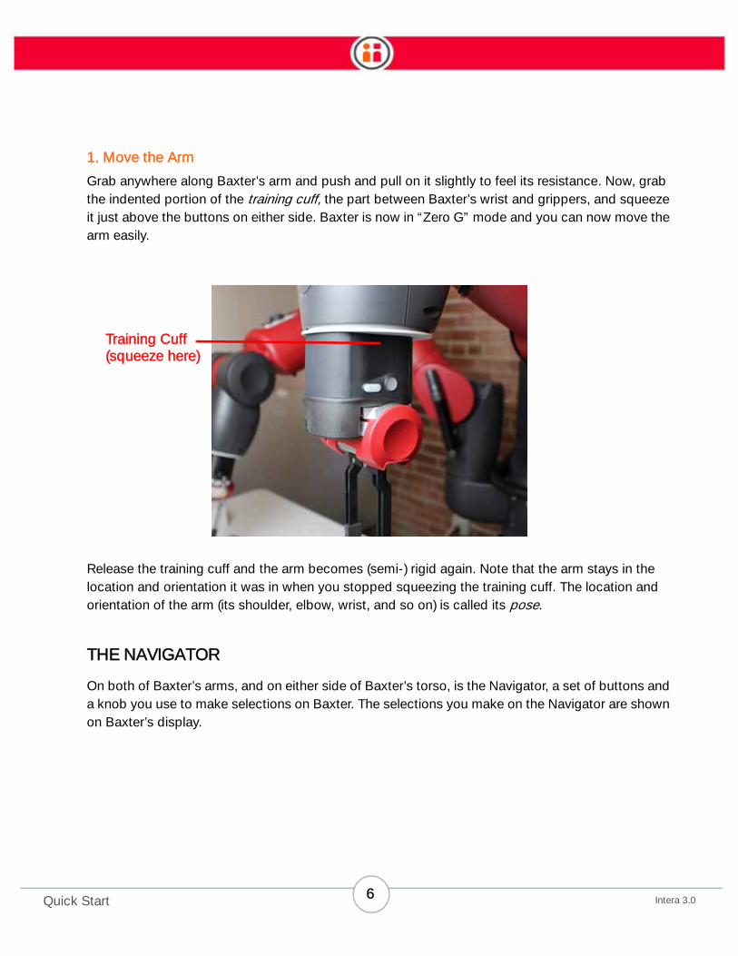
1. Move the Arm
Grab anywhere along Baxter’s arm and push and pull on it slightly to feel its resistance. Now, grab
the indented portion of the training cuff, the part between Baxter’s wrist and grippers, and squeeze
it just above the buttons on either side. Baxter is now in “Zero G” mode and you can now move the
arm easily.
Release the training cuff and the arm becomes (semi-) rigid again. Note that the arm stays in the
location and orientation it was in when you stopped squeezing the training cuff. The location and
orientation of the arm (its shoulder, elbow, wrist, and so on) is called its pose.
THE NAVIGATOR
On both of Baxter’s arms, and on either side of Baxter’s torso, is the Navigator, a set of buttons and
a knob you use to make selections on Baxter. The selections you make on the Navigator are shown
on Baxter’s display.
Training Cuff
(squeeze here)
6Intera 3.0Quick Start

2. Create a New Task
The work you train Baxter to perform is called a task. A task can be very simple, like the pick and
place you’re about to create, or much more complicated, involving both of Baxter’s arms moving in
a coordinated fashion to and from multiple pick and place locations, holding a variety of poses, and
sending and receiving signals from other machines and devices.
NOTE: A task is always made up of at least one pick followed by a place.
Back Button
Scroll Knob/
OK Button
Baxter Button
7Intera 3.0Quick Start

You can both scroll the knob to move through options on Baxter’s display, or press it to make a
selection. We refer to pressing the scroll knob to make a selection as “pressing the OK button” or
sometimes, “press OK on the Navigator.”
Generally you press the Back button on the Navigator when you want to return to the previous
screen or cancel your last action.
Scroll the knob to reveal the main button bar and stop scrolling when you reach the New Task icon
(as shown here).
Press OK on the Navigator. Baxter displays the Task Map, which is a kind of map of the work area
and Baxter’s location in it.
8Intera 3.0Quick Start

For now you just need to know that the blue icon on the display represents Baxter’s right arm, the
green icon represents the left arm, and the shaded area is where the arms can reach.
Squeeze the training cuff and move one of Baxter’s arms. Watch as the appropriate icon moves on
screen in response to the movement of the arm.
3. Grasp an Object
Place an object on the work surface for Baxter to grasp.
Remember: For you to train a pick and place, Baxter must have at least one arm with a properly
working gripper attached. If not, follow the gripper kit instructions and install a gripper now.
If your Baxter has parallel electric grippers installed, make sure the grippers are open, then position
the fingers on either side of the object. If you’re using the vacuum grippers, position the object just
touching the vacuum cup.
Press the Grasp button on the training cuff.
9Intera 3.0Quick Start

Baxter grabs the object and nods its head acknowledging your instruction. If you look at Baxter’s
display, you’ll see an icon for a Pick, plus a sub-task number and letter. (For details, see “What Are
Tasks and Sub-tasks?” on page 26.)
Still squeezing the training cuff, move the arm to the location where you want Baxter to place the
object, then press the Grasp button again to release the object. Baxter nods and releases the
object.
The Task Map displays the icon for a Place (along with sub-task number and letter).
Reset the object to its original position, select Run or Reset, and watch Baxter perform the task.
You just trained your first task using Baxter.
Grasp button
10Intera 3.0Quick Start
Getting to Know Baxter
Setting Up Baxter
To prepare for the arrival and setup of Baxter, read the Baxter Pre-Delivery Guide. The document
arrives in an email prior to the delivery of your order.
To set up Baxter:
• Locate the installation card that ships with the robot. Follow the instructions to
assemble the pedestal (if ordered), and attach Baxter to the pedestal or alternate
work surface.
• Follow the instructions included with the gripper kit to install a gripper.
If you misplace these documents, just send us an email at [email protected]. We’ll send
you PDF versions of the documents.
Accessories
Included accessories:
• Power cord
• E-stop button and 10-foot cable
Required accessories (Baxter requires at least one of the following per arm):
• Rethink Robotics Electric Parallel Gripper Kit
• Rethink Robotics Vacuum Cup Gripper Kit
Optional accessory: Baxter pedestal
11Intera 3.0Getting to Know Baxter

Anatomy
Front View
1. Condition ring
2. Attention ring
3. Display
4. Torso
5. Navigator (one on each forearm)
6. Lower front panel
7. Training cuff (shown with parallel
gripper)
8. Training cuff (shown with vacuum
gripper
9. Pedestal (optional)
1
3
2
6
87
9
5 5
4
12Intera 3.0Getting to Know Baxter

Back View
Grippers
Grippers (a required accessory) are the robot’s hands—they enable Baxter to grasp and release
objects. The grippers attach to the wrist plate at the base of the robot’s training cuff. Currently,
Baxter supports two standard Rethink Robotics grippers: electric parallel and vacuum cup.
After installing or altering a gripper, see “Appendix A: Configuring Grippers” on page 118 to
configure it. (Note that installation and alteration instructions ship with the gripper kit.)
Note: Custom finger lengths are supported and can be entered into the software, but
custom widths are not currently supported by the software.
1
2
3
5
1. Navigator (one on each side)
2. Non-active (button for future use)
3. Air filter (one on each side)
4. Power button
5. Power and I/O panel (with DB15, USB,
and Ethernet Ports)
6. Pedestal (optional)
6
4
13Intera 3.0Getting to Know Baxter

ELECTRIC PARALLEL GRIPPER
1. Training cuff
2. Gripper body
3. Fingers
4. Finger positions (four-position
gripper shown)
2
1
3
4
14Intera 3.0Getting to Know Baxter

VACUUM CUP GRIPPER
1. Training cuff
2. Gripper body
3. Pneumatic tube fitting
4. Vacuum cup
4
1
2
3
15Intera 3.0Getting to Know Baxter

How to Communicate with Baxter
Using the Training Cuffs
Use the training cuffs to move the arms, to manipulate the state of the grippers, and secondarily, to
select on-screen options.
Training cuff switch: Squeeze this switch at the indentation in the cuff to move the robot’s arm. When this
switch is squeezed, the blue indicator on the arm’s navigator button lights up.
Grasp button: Press to toggle a parallel gripper open or closed, or a vacuum gripper on or off.
Action button: Press to select items on the display screen. Create waypoints, Hold actions; select, copy,
or move actions on the task map, as well as outline a visual search area.
1
32
1. Training cuff switch
2. Grasp button
3. Action button
16Intera 3.0Getting to Know Baxter

Navigating the Screens
Use the navigator on either of the arms to scroll to and interact with options on the screen. When
you press the OK button (2), the blue indicators on the navigator light up.
Back button: Press to exit the current screen and return to the previous screen. Will also cancel the last
action.
Knob: Scroll the knob to move between on-screen options. Press the knob (OK) to select an option.
OK indicator light: When an OK button on either the cuff or navigator is pressed, the white indicator
around the knob lights up.
Baxter button: Press to display options for the current screen.
Training cuff indicator: When the switch on the cuff is squeezed, the blue indicators along the top and
bottom edge of the navigator light up.
1
4
3
5
2
1. Back button
2. Knob (turn to scroll) and OK button
(press)
3. OK indicator light
4. Baxter button
5. Training cuff indicator lights
17Intera 3.0Getting to Know Baxter

Moving the Arms
To move an arm, squeeze the cuff at the indentation just above the other buttons, and push or pull
the arm to the location you want.
Squeezing the cuff releases the tension and resistance in the arm, making it easier to manipulate.
With its seven degrees of freedom—an incredible amount of flexibility—Baxter enhances arm
stability by attempting to fix its elbow in position whenever the lower arm is moved.
Note: When the switch is pressed, the blue indicator lights illuminate on the
corresponding navigators on the arm and torso.
Training cuff switch
18Intera 3.0Getting to Know Baxter

When grasping the training cuff, you can move the arms by either repositioning the lower arm or
changing the height of the elbow.
Grasping Objects
Training involves showing Baxter how to pick up and place objects.
To move the lower arm: While squeezing the cuff (1), move the robot’s arm to the desired location.
To move the elbow: By design, the elbow (2) will try to maintain its current height and will spring back if
you do not actively reset it. While squeezing the cuff, move the elbow to the desired position. Continue to
hold the elbow at the new location, and release the cuff. This will reset the elbow at the new position.
To grasp an object: Position the gripper over the object, press Grasp.
To release an object: With an object in the robot's hand, press Grasp.
To toggle the state of the gripper: Without an object in hand, press Grasp twice quickly.
1
2
19Intera 3.0Getting to Know Baxter

How Baxter Communicates
Baxter communicates through a combination of eye expressions, light rings, and thought bubbles.
Baxter also responds to touch on a navigator or a training cuff—it stops moving and turns its head
in the direction of contact on any of its primary touch points.
Eye Expressions
Baxter displays one of six eye expressions in response to what it is doing or what it senses
happening in its environment.
Neutral Concentrating Confused
Surprised Sad Sleeping
20Intera 3.0Getting to Know Baxter

The surprised expression is emphasized with an orange background when Baxter is working and
unexpectedly detects someone has entered its space (currently, this only happens when a safety
mat is connected and stepped on); Baxter also automatically slows its movement.
Attention Ring
The attention ring lights appear in clusters of two or three when Baxter detects movement.When
Baxter is confused, the yellow lights in the ring appear and flash simultaneously.
Attention ring
21Intera 3.0Getting to Know Baxter

Condition Ring
The condition ring communicates the condition of the robot.
Light Color and Pattern What it Means
Solid green Baxter is working
Slow pulsing green User is interacting with Baxter
Solid yellowBaxter is confused and needs
user assistance
Slow blinking yellow Baxter is sleeping
Fast blinking red Baxter reports an error
Condition ring
22Intera 3.0Getting to Know Baxter

Thought Bubbles
Baxter displays a thought bubble when it needs assistance. For example, in the illustration below,
the thought bubble indicates that the E-stop button is engaged or disconnected. Baxter cannot
continue until the E-stop is disengaged, or reconnected and reset.
When you see a thought bubble, touch the training cuff for more information (if available).
“Light Bulb” Tips
When you see a "light bulb" symbol on a screen, that means there is a tip (or tips) on how to use that
functionality. Select the light bulb to display the tip. (These tips are available on the Modify Waypoints Screen,
the Advanced Screen, and the Action Practice screens. )
Example of a “light bulb” tip
23Intera 3.0Getting to Know Baxter

Main Screen
The main screen has two elements: the button bar, and eye expressions.
1. Current task name – in this image, “Assemble Kit 2.”
2. Current task options
• Run – run the task.
• Reset – reset the count, and restart the task from the first action.
• Modify – open the task map for the task.
3. Main options
• New – create a task.
• Tasks – open the task gallery, a visual list of existing saved tasks.
• Settings – open Baxter administration and advanced options.
• Sleep – open Baxter power options: Sleep, Restart, Shutdown, Logoff
(unused).
4. Baxter eyes – Baxter uses eye expressions to communicate its current state.
To navigate a button bar: Rotate the knob to scroll (referred to as “scrolling”) through options. When the
option is highlighted, press the knob (OK) to select it.
To exit a button bar option: Press Back .
1
2 3
4
24Intera 3.0Getting to Know Baxter

Turning On Baxter
Press the white power button on the lower left back of the robot (see “Back View” on page 13 for
the location). The lights on the head turn on, and the main screen appears on the Baxter display.
25Intera 3.0Getting to Know Baxter

Training and Managing Tasks
What Are Tasks and Sub-tasks?
Baxter is designed to pick up objects from locations you define and place them in locations you
define. When Baxter picks up an object, it then needs to put the object down before it can pick up
another one. Thus each Pick action you train Baxter to perform also requires at least one Place
action. And that Place must come after the Pick.
• A task is a series of one or more Pick and Place action combinations trained on
an arm.
• Each Pick and Place action combination is called a sub-task.
• Hold actions can be added to any sub-task. (See “Hold” on page 89.)
• To make it easier to distinguish one action from another, actions are labeled on
the Task Map (see page 28) with the subtask number and appended with a letter.
For example, if subtask 1 includes a Pick>Hold>Hold>Place, the actions on the
Task Map will be labeled:
-- Pick 1A
-- Hold 1B
-- Hold 1C
-- Place 1D
Example of a subtask Place action with identifying labels
Each arm functions independently by default and is able to learn its own unique sub-tasks. You can
also train Baxter to coordinate sub-tasks and share locations across arms.
26Intera 3.0Training and Managing Tasks

Baxter can pick up objects blind or by using its cameras.
• Blind – Baxter picks an object from a fixed location.
• Visual – Baxter learns the shape of an object, and uses vision to identify it and
pick it up. Objects may or may not be in the same location. See “Training a Pick
Using Vision” on page 34
Note: Vision is only available for vertical Pick actions.
Each action has a location associated with it. You can customize actions by:
• Adding count – Baxter picks or places a fixed number of objects. (For Hold
actions, you can change time instead of count.)
• Adding signals – Baxter sends or waits for a signal before or after performing the
action.
• Changing paths - You can change the way Baxter's arm moves between two
actions.
• Changing the approach and retract distance – Baxter begins and ends the
actions from a specified distance.
• Changing the speed - As Baxter approaches or retracts from an action, you can
specify when Baxter slows down.
• Changing the drop height – For vertical actions, Baxter drops the object into the
Place location from a specified height.
• Add object weight – For Pick actions.
• - Baxter can be instructed to Pick (or Place) an object when it arrives at a
location, when it senses contact, or whichever comes first. (See “How to Make
Detailed Modifications to an Action (Advanced Settings Screen)” on page 68.)
If you train multiple sub-tasks per arm, you can order them in the sequence you want Baxter to
perform them.
The Difference Between Vertical and Non-vertical Tasks
The only difference between vertical and non-vertical tasks (as of Intera software 3) is that vision
search is available only for vertical Picks. The camera does not operate for non-vertical tasks. There
are no performance differences between the two types of tasks.
Non-vertical actions are identified by a "dot" symbol. These symbols show up on the Task Map
when an action is highlighted or on the action's modify panel.
27Intera 3.0Training and Managing Tasks

Examples of non-vertical (left) and vertical (right) place action icons
The Task Map
The task map is a graphical representation of the Baxter workspace. When you train Baxter to
perform a task, the map displays icons that represent each of the actions included in the task. The
icons are color-coded to match the arm on which the action was trained; blue (on the left of the
screen) is the robot’s right arm, green (on the right of the screen) is the left.
There are several ways to access the Task Map, including:
• Creating a new task
• Modifying an existing task
• Selecting a task from the Task Gallery
The gray, overlapping shapes—called the workspace—represent the maximum mechanical reach of
each of the Baxter arms if the arms are fully extended and parallel to the shoulder joint. Baxter can
execute actions within this area.
The overlapping darker area towards the center of the workspace indicates the area shared
between both arms, enabling the arms to operate within the same workspace.
Note: The robot's arms move within a sphere defined by the center point of the shoulder
axis and the full reach of the arm. The actual reach of the arm at any given location is
affected by the height of the robot's arm and angles of the joints. Actions are therefore
limited at different heights and joint angles. The approach and retract distances for an
Action may also limit where the Action can be performed.
Tip: Baxter performs tasks more efficiently when the objects are located close to the
center of the workspace.Tasks trained at the extremes of the workspace approach joint
limits and are sometimes more difficult to execute consistently.
28Intera 3.0Training and Managing Tasks

THE TASK MAP LABELS
1. Baxter workspace
2. Right arm Place action
3. Right hand location
4. Right arm Pick action
5. Left arm Place action
6. Task name
7. Left hand location
8. Left arm Pick action
1
62
3
84
5
7
29Intera 3.0Training and Managing Tasks
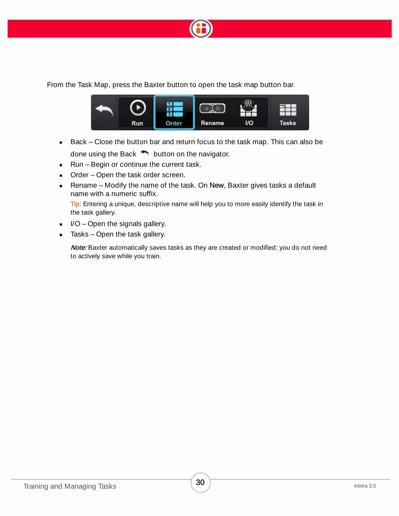
From the Task Map, press the Baxter button to open the task map button bar.
• Back – Close the button bar and return focus to the task map. This can also be
done using the Back button on the navigator.
• Run – Begin or continue the current task.
• Order – Open the task order screen.
• Rename – Modify the name of the task. On New, Baxter gives tasks a default
name with a numeric suffix.
Tip: Entering a unique, descriptive name will help you to more easily identify the task in
the task gallery.
• I/O – Open the signals gallery.
• Tasks – Open the task gallery.
Note: Baxter automatically saves tasks as they are created or modified; you do not need
to actively save while you train.
30Intera 3.0Training and Managing Tasks
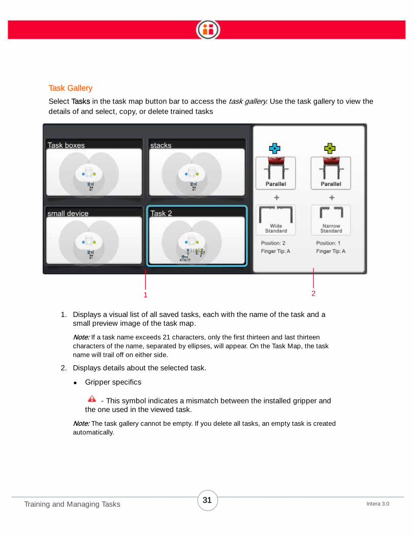
Task Gallery
Select Tasks in the task map button bar to access the task gallery. Use the task gallery to view the
details of and select, copy, or delete trained tasks
1. Displays a visual list of all saved tasks, each with the name of the task and a
small preview image of the task map.
Note: If a task name exceeds 21 characters, only the first thirteen and last thirteen
characters of the name, separated by ellipses, will appear. On the Task Map, the task
name will trail off on either side.
2. Displays details about the selected task.
• Gripper specifics
- This symbol indicates a mismatch between the installed gripper and
the one used in the viewed task.
Note: The task gallery cannot be empty. If you delete all tasks, an empty task is created
automatically.
1 2
31Intera 3.0Training and Managing Tasks

From the task gallery, press the Baxter button to open the task gallery button bar.
• Back – Close the button bar and return focus to the task gallery. This can also be
done with the Back button on the navigator.
• Open – Open the task map for the highlighted task.
• Rename – Modify the name of the task. On New, Baxter gives tasks a default
numeric name.
Tip: Rename a task with a descriptive name when you first create it so that you can easily
identify it later in the task gallery.
• Delete – Delete the task.
Note: Baxter must always have at least one task stored. If only one task exists, and it is
deleted, Baxter will create a new “empty” task.
IMPORTANT Once the deletion is confirmed, the deleted task cannot be restored.
• Copy – Create a new task based on the current one.
• New – Create a new, empty task and open the task map.
To navigate to a task: Rotate the knob to scroll through the tasks.
To select and open a task: Scroll to the task until it is highlighted, and press OK. A larger preview of the
task map opens in the left panel, and the task gallery button bar opens at the bottom of the screen.
32Intera 3.0Training and Managing Tasks
Training a Blind Pick
To train a basic blind Pick and Place task:
1. In the main button bar, click New.
2. Place the object you would like Baxter to grasp in the fixed location of the Pick.
3. Move the arm to the location, with the gripper’s fingers poised to grasp the
object. (If using a vacuum gripper, place the suction cup on top of the object.)
4. Press the Grasp button on the training cuff. Baxter grasps the object.
5. Move the arm to the location where you want to place the object.
6. Press the Grasp button. Baxter releases the object.
7. Press Back to open the Main Button Bar, then select Reset or Run to perform the
task.
Use the navigator buttons and display screens to customize the type of Pick/Place actions you
want each arm to perform.
Tip: If Baxter’s wrist is not pointing straight down when performing an action, meaning
the action is not vertical, a red circle is displayed next to the blue (for Baxter’s right arm)
or green (for Baxter’s left arm) pointer. Non-vertical Picks can only be blind Picks; they
cannot use vision. If the pointer is not blue or green but gray, Baxter cannot create an
action in that location/pose.
33Intera 3.0Training and Managing Tasks

Training a Pick Using Vision
In some situations you will need Baxter to visually search for and recognize an object before picking
it. Train a Pick using vision when:
• You want Baxter to locate an object that varies in location and/or orientation by
more than 0.2 inches (0.5 cm) each time.
• You want Baxter to pick from a continuously moving conveyor. (Note: A conveyor
that has been indexed would not require vision.)
Important Note:
Vision only works for vertical Picks. With the Intera 3.0 software, Picks are set to
non-vertical by default. So, to make a Pick Action vertical:
1. Highlight the Pick on the Task Map and press OK on the Navi-
gator.
Baxter displays the Pick's Modify panel.
2. Scroll to the icon and press OK.
3. Select the Settings icon on the Screen.
Baxter displays the Advanced Settings Screen.
4. Check the Snap to Vertical check box, the select Done.
5. Press the Back button on the Navigator to return to the Task
Map and select the Pick.
It will now be a vertical Pick.
34Intera 3.0Training and Managing Tasks
• You want Baxter to automatically detect when materials are replenished. (You
can also use signals for this purpose). If nothing changes in the search field,
Baxter will eventually time out.
• Baxter needs to identify a particular object from other, different nearby objects.
Consider the following when training Baxter to look for an object:
• Baxter works best when its workspace is lit with bright, diffused lighting with
minimal shadows.
• Shadows in the work area, including those created by the object, degrade
Baxter’s ability to see an object. So does glare, from the object or the work
surface.
• In general, the higher the contrast between the object and the work surface, the
better. Although when trying to see texture on a white or light-colored object, you
may need to lower contrast/video gain.
• A clutter-free work surface works best.
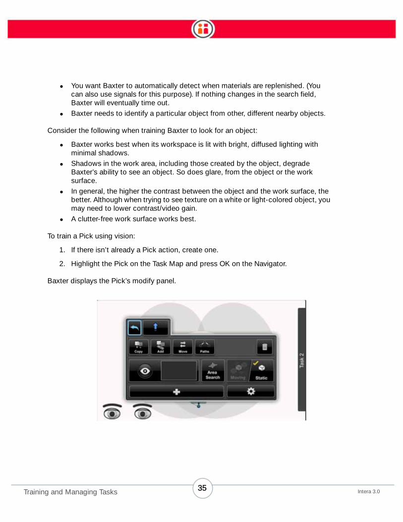
To train a Pick using vision:
1. If there isn’t already a Pick action, create one.
2. Highlight the Pick on the Task Map and press OK on the Navigator.
Baxter displays the Pick’s modify panel.
35Intera 3.0Training and Managing Tasks
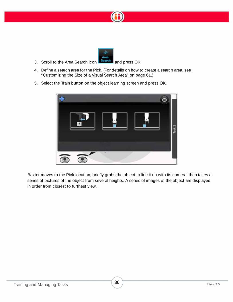
3. Scroll to the Area Search icon and press OK.
4. Define a search area for the Pick. (For details on how to create a search area, see
“Customizing the Size of a Visual Search Area” on page 61.)
5. Select the Train button on the object learning screen and press OK.
Baxter moves to the Pick location, briefly grabs the object to line it up with its camera, then takes a
series of pictures of the object from several heights. A series of images of the object are displayed
in order from closest to furthest view.
36Intera 3.0Training and Managing Tasks

Generally, Baxter will be able to recognize the object if the yellow overlay completely outlines the
object.
6. If Baxter cannot recognize the object, first try again, keeping in mind the
troubleshooting tips (See “Troubleshooting tips:” on page 42) You can also adjust
the camera settings (See “Camera Settings” on page 43.)
7. If that doesn’t work, retrain the grippers. (Go to Settings -> Hardware -->
Configure End Effectors (image below). Retraining the grippers is a process in
which Baxter learns what the grippers look like so they can be ignored while
looking for objects. When retraining, ensure all blue or yellow pixels are removed
from the screen except for the gripper fingers or vacuum cup.
37Intera 3.0Training and Managing Tasks

8. From the vision screen, press OK to select the picture that best represents the
shape of the object, then press the Next button.
Baxter takes more pictures of the object from various locations to gather more data and refine its
perception of the object.
When done, Baxter displays a live view of the object on the Test and Select Model screen.
38Intera 3.0Training and Managing Tasks

• The blue outline identifies Baxter’s understanding of where the object is.
• The yellow circle represents Baxter’s view of the center point of the axes of the
object.
• The red arrow illustrates how Baxter perceives the orientation of the object for
gripping.
When the arrow points straight up (in twelve o’clock position) and the circle is fully yellow as in the
figure above, that is a valid alignment for gripping: Baxter can pick up the object.
39Intera 3.0Training and Managing Tasks

If the arrow is not straight up and/or the circle is not completely yellow, as in the above figure, Bax-
ter may not be able to grip the object, or it will have to turn its wrist during the Pick in order to grip
the object.
You may play with the placement and orientation of the object at this stage – in live view – to see
how Baxter’s ability to recognize the object is affected. A flickering outline and/or fading yellow cir-
cle and arrow indicate weaker detection. In that case, try another detector for improved reliability.
40Intera 3.0Training and Managing Tasks

On the left side of the screen, Baxter flags the recommended model of the object with a star
symbol. Other possible models are also displayed. In general you will want to use Baxter’s recom-
mended model, but advanced users, or users looking for a particular type of model by which to rec-
ognize the object in question, may want to select from the list.
41Intera 3.0Training and Managing Tasks

You can get further information about each of the models by pressing the Baxter button on the Nav-
igator. That displays which “detector” Baxter used to identify the part along with other information,
for example, the diameter of the part, what information (texture, contrast, background, boundary) it
considered when building the model, etc.
9. Select the best model. The object is now trained.
TROUBLESHOOTING TIPS:
If Baxter did not locate the object, or if the object is not correctly covered by the overlay, try the fol-
lowing:
• Adjust the lighting in the work area to improve the contrast and remove
shadows around the object.
• Change the contrast between the object and the work surface by placing
the object on a piece of paper.
• Remove any clutter near the object.
• Change the camera settings. See “Camera Settings” on page 43.
42Intera 3.0Training and Managing Tasks
Camera Settings
You can change the settings for Baxter’s cameras to adjust for the amount and quality of light Bax-
ter perceives in the work area. (Technical note: the adjustments apply primarily to the lighting vari-
ables of gain, white balance, and exposure.) You can make adjustments using a simple slider or you
can let Baxter adjust its own camera lighting settings automatically by selecting the Auto checkbox.
This capability is available per task, per arm.
Note: When you create a new task, the current camera settings are inherited based on the previous
open task.
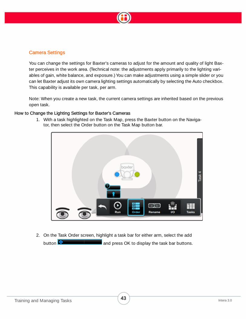
How to Change the Lighting Settings for Baxter’s Cameras
1. With a task highlighted on the Task Map, press the Baxter button on the Naviga-
tor, then select the Order button on the Task Map button bar.
2. On the Task Order screen, highlight a task bar for either arm, select the add
button and press OK to display the task bar buttons.
43Intera 3.0Training and Managing Tasks

1. Select the advanced settings icon .
2. Select the camera settings button.
Baxter displays a live camera view.
44Intera 3.0Training and Managing Tasks
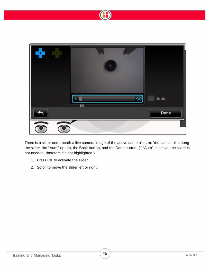
There is a slider underneath a live camera image of the active camera’s arm. You can scroll among
the slider, the “Auto” option, the Back button, and the Done button. (If “Auto” is active, the slider is
not needed, therefore it’s not highlighted.)
1. Press OK to activate the slider.
2. Scroll to move the slider left or right.
45Intera 3.0Training and Managing Tasks
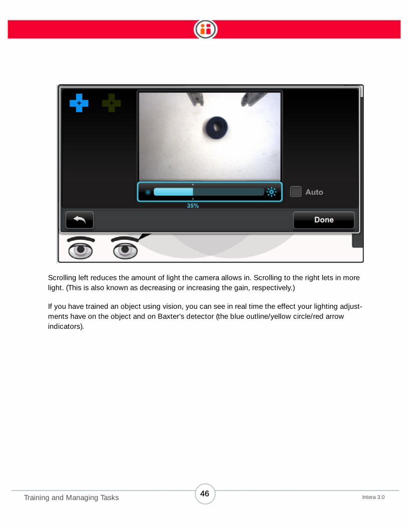
Scrolling left reduces the amount of light the camera allows in. Scrolling to the right lets in more
light. (This is also known as decreasing or increasing the gain, respectively.)
If you have trained an object using vision, you can see in real time the effect your lighting adjust-
ments have on the object and on Baxter’s detector (the blue outline/yellow circle/red arrow
indicators).
46Intera 3.0Training and Managing Tasks

3. When you’re satisfied with the appearance of the live image, press Done.
Note: You can also change the camera settings from the Object Training screen.
Training a Group of Pick or Place Actions
When you need Baxter to pick a group of objects from a number of individual locations, or place
them in a number of individual locations (e.g., when moving items from or into a segregated box or
tray), create an action group. Note that just as Baxter remembers the order of individual actions that
you train it to perform, it will also remember the order of actions within an action group. Also, when
you make changes to an action group, it affects all actions within the group.
47Intera 3.0Training and Managing Tasks

NOTE: If, when training Baxter, you need to put an object in the gripper and you don’t want to copy
or add a new action, double-click the grasp button.
To create an action group:
1. Highlight the action you want to use to start a group. Press OK.
2. Scroll to and click Add on the Modify window.
3. On the Task Map, you'll see an icon labeled "Add." Move the robot's hand to the
second desired location, and press the action button. (You can also press OK, but
the action button is usually more convenient.) The added action is placed in the
location.
4. Repeat as many times as needed.
5. When finished, press the Back button. (Don’t press OK to finish. That will continue
to add locations to the action group.)
48Intera 3.0Training and Managing Tasks
Managing Tasks and Sub-tasks
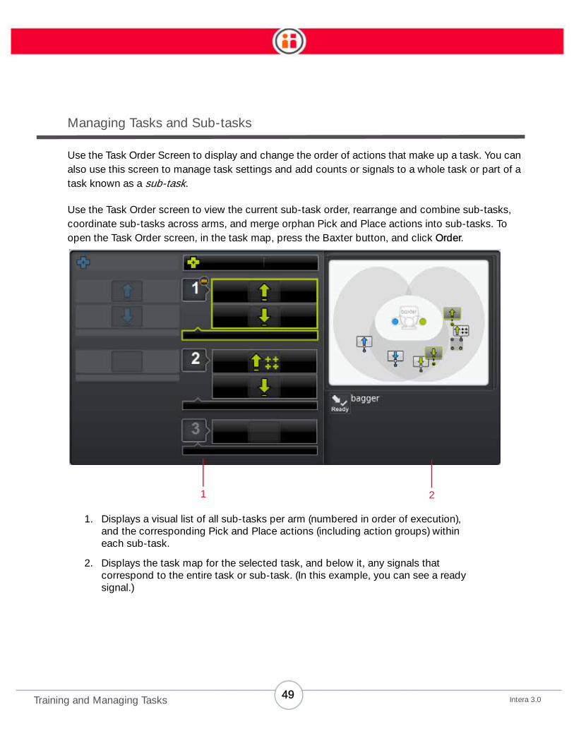
Use the Task Order Screen to display and change the order of actions that make up a task. You can
also use this screen to manage task settings and add counts or signals to a whole task or part of a
task known as a sub-task.
Use the Task Order screen to view the current sub-task order, rearrange and combine sub-tasks,
coordinate sub-tasks across arms, and merge orphan Pick and Place actions into sub-tasks. To
open the Task Order screen, in the task map, press the Baxter button, and click Order.
1. Displays a visual list of all sub-tasks per arm (numbered in order of execution),
and the corresponding Pick and Place actions (including action groups) within
each sub-task.
2. Displays the task map for the selected task, and below it, any signals that
correspond to the entire task or sub-task. (In this example, you can see a ready
signal.)
1 2
49Intera 3.0Training and Managing Tasks

To make changes to the task for that arm, select the corresponding bar, at the top. To make
changes to any sub-task, select the task and press OK. The button bar for the task or sub-task
appears.
Task Button Bar
• Back – Close the button bar and return focus to the task order screen.
• Count – Change count to a task for one or both arms.
• Signals – Add a signal to a sub-task, or remove one. (See “Signals” on page 89.)
• Motion Presets - Define how Baxter's arm follows a path's waypoints. These
presets will help Baxter complete a wider variety of tasks. (See “Motion Presets”
on page 86.)
• More Options – Insert a time delay after each performance of a task (Auto Task
Delay); access camera settings (see “Camera Settings” on page 43); the option
to make the arms move to the same place before starting a task (see “Start at
Current Arm Pose” on page 57); and custom gripper settings (see “Applying
Custom Gripper Settings” on page 53).
Sub-task Button Bar
Top row, left to right:
• Back – Close the button bar and return focus to the task order screen.
• Count – Add count to a sub-task.
50Intera 3.0Training and Managing Tasks

• Copy – Copy a sub-task and all its details to the same location on the Task Map.
The copied sub-task will appear on the Task Map just below the original.
• Signals – Add a signal to a sub-task, or remove one. (See “Signals” on page 89.)
Second row, left to right:
• Rename - Create or change the name of the selected sub-task.
• Reorder – Reorder sub-tasks for the selected arm. You can also merge
incomplete sub-tasks.
• Coordinate Order (Across Arms) – Shift when a sub-task begins on one arm in
relation to a sub-task on the other arm. If the sub-task is already coordinated,
this button becomes “uncoordinate.”
• Combine – Combine two sub-tasks on one arm into one sub-task. The
highlighted sub-task moves into the sub-task below it.
• Delete – Delete the current sub-task on an arm.
Coordinating Sub-tasks Across Arms
Coordinating arms allows Baxter to conduct a sub-task on one arm before conducting a sub-task
on the other arm.
1. Pick the sub-task you want to move relative to the other arm. Press OK.
To reorder or merge sub-tasks:
1. In the sub-task order button bar, click the reorder icon.
2. Scroll up or down. A yellow line appears to indicate the new location.
3. Press OK to move or merge the sub-task.
To name a sub-task:
1. From the Order screen, highlight the sub-task you want to name and press OK.
2. Select “Rename” from the Sub-task menu.
3. Use the text wheel to create a name for the selected sub-task.
4. Select OK.
You can also modify or delete sub-task names.
51Intera 3.0Training and Managing Tasks

2. Click the coordinate icon in the sub-task order button bar. A yellow line appears
in the list of sub-tasks on the other arm (In this example, the user wants to move
the second sub-task on the left [green] arm.).
3. Scroll to the right or left to move the yellow line until it appears after the sub-task
that the selected sub-task should follow.
4. Press OK.
52Intera 3.0Training and Managing Tasks

After the sub-tasks are coordinated, a gray line appears between them to
indicate the order.
To uncoordinate sub-tasks across arms, highlight the sub-task used to coordinate arms and scroll
to the coordinate option. It will now read "uncoordinate". Select it and that coordination will be
removed.
Combining Sub-tasks
Combining sub-tasks within an arm lets the robot decide when to complete part of a task. For
example, if three parts need to go onto a tray, but the order does not matter, you can combine each
sub-task into one large sub-task, and Baxter will determine in which order to complete the sub-
tasks. Baxter will combine two sub-tasks next to each other on the same arm.
1. Select the first sub-task of the two.
2. In the sub-task order button bar, click the combine icon. The selected sub-task
merges with the one below it.
Note: It is not possible to split combined sub-tasks.
Applying Custom Gripper Settings
Apply custom gripper settings to optimize Baxter gripper performance with a wide variety of
objects.
53Intera 3.0Training and Managing Tasks
Note: These settings apply to both Rethink Robotics grippers and custom grippers, and are applied
for all actions on an arm for that task.
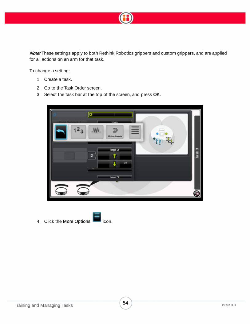
To change a setting:
1. Create a task.
2. Go to the Task Order screen.
3. Select the task bar at the top of the screen, and press OK.
4. Click the More Options icon.
54Intera 3.0Training and Managing Tasks

5. Click the Gripper Settings icon.
6. Change the setting.
ELECTRIC PARALLEL GRIPPER SETTINGS:
• Gripper Speed (%): Gripper closing speed as a percentage of maximum.
• Release Speed (%): Gripper opening speed as a percentage of maximum.
• Holding Force (%): Force required to hold a part once it’s grasped.
Note: Do not set the Holding Force %value to less than the Grip Detection Force (%).
• Grip Detection Force (%): Threshold for grip detection—the amount of force
required to detect when an object is grasped before the robot moves to the next
action.
Note: If the force is set too high, a soft object in the gripper may not be detected. Set high
initially, and back it off if the gripper is crushing things.
55Intera 3.0Training and Managing Tasks

VACUUM CUP GRIPPER SETTINGS:
• Blow off time (sec): Amount of time the vacuum gripper will blow air when releas-
ing an object. (Note that this feature requires additional “plumbing.”)
• Grip Detection Threshold (%): Threshold in which the vacuum sensor detects a
successful pick. This setting is intended for custom vacuum cup grippers and/or
3rd party vacuum cups, and is dependent on the mechanical properties of the
vacuum cup mechanism.
Examples:
• For a single piece of paper, which is likely porous, set a lower threshold.
That tells Baxter the material is porous and the gripper sensor will trigger
at a lower threshold.
• For a rigid non-porous object, less of a vacuum is required, so set a
higher threshold. Setting a higher threshold ensures the object in the
gripper does not trigger prematurely.
• When using a custom vacuum gripper, it is a best practice to start with a
higher percentage, and reduce the value as needed.
• Grip Attempt Timeout (sec): Duration in which a vacuum end effector attempts to
grip an object before stopping the attempt.
56Intera 3.0Training and Managing Tasks
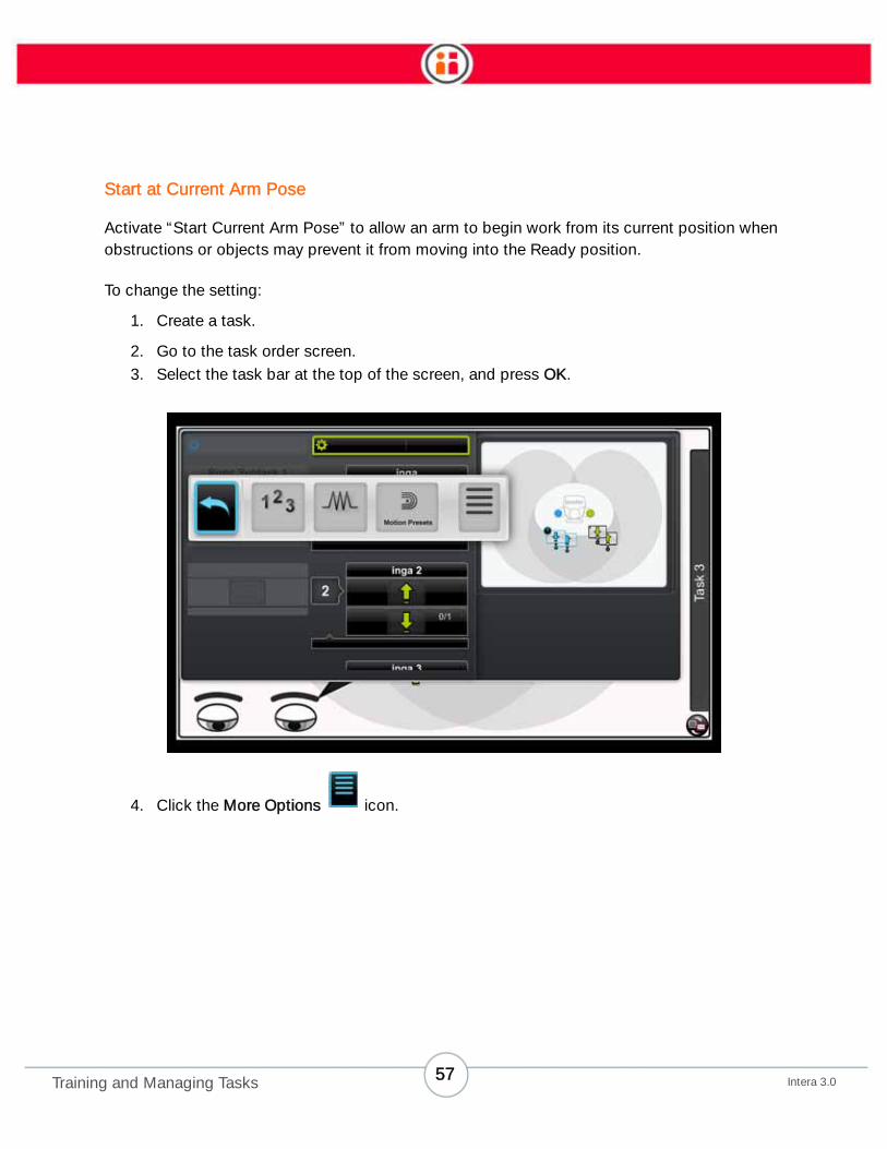
Start at Current Arm Pose
Activate “Start Current Arm Pose” to allow an arm to begin work from its current position when
obstructions or objects may prevent it from moving into the Ready position.
To change the setting:
1. Create a task.
2. Go to the task order screen.
3. Select the task bar at the top of the screen, and press OK.
4. Click the More Options icon.
57Intera 3.0Training and Managing Tasks

5. Click the Start at Current Arm Pose setting icon.
6. Check the box for “On Run or Reset, start at current arm pose.” (The box is
checked by default.)
58Intera 3.0Training and Managing Tasks
Modifying Actions
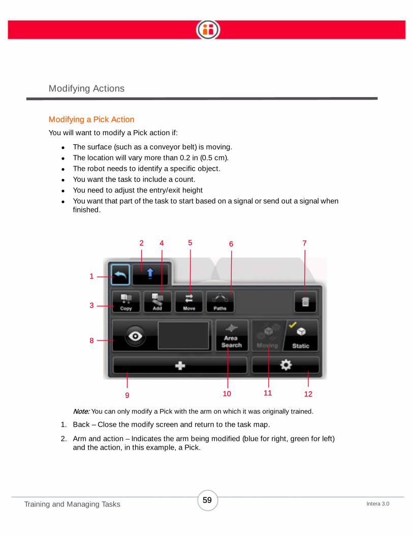
Modifying a Pick Action
You will want to modify a Pick action if:
• The surface (such as a conveyor belt) is moving.
• The location will vary more than 0.2 in (0.5 cm).
• The robot needs to identify a specific object.
• You want the task to include a count.
• You need to adjust the entry/exit height
• You want that part of the task to start based on a signal or send out a signal when
finished.
Note: You can only modify a Pick with the arm on which it was originally trained.
1. Back – Close the modify screen and return to the task map.
2. Arm and action – Indicates the arm being modified (blue for right, green for left)
and the action, in this example, a Pick.
1
3
8
2 4 65
109 11 12
7
59Intera 3.0Training and Managing Tasks

3. Copy – Copy the current action (and all its modified details). Creates an action
group.
4. Add - Similar to Copy, but this icon enables you to add additional locations to the
original, making an action group. (See “Training a Group of Pick or Place Actions”
on page 47.) To add to an existing action group, choose any single action in the
group, then select Add.
5. Move – Move the location where the action takes place. (Note that this will delete
the path to the Action, so you may want to use and Modify to preserve the path.)
6. Paths - Select from the Task Map a path you want to modify.
7. Delete – Delete the action. You’ll be prompted to confirm the deletion:
Note: Once deleted, an action cannot be restored.
8. Visual pick training – Preview only. If a Pick on the arm includes a trained object,
a small preview image of the object is displayed. Teach Baxter to recognize an
object (see “Training a Pick Using Vision” on page 34).
9. Add Features – Adjust more details:
• Add Count – Specify the number of times an action should be completed.
• Add Signal – Specify which defined signal(s) you want to attach.
• Add Weight - Specify a weight for the object Baxter will hold for a task.
10. Area Search - Define the area to search for the Pick.
11. Work surface type (vision only) – Toggle between a moving surface (conveyor)
and a static one (table).
12. – Practice or modify the approach, retract, or action poses. You can also change
the distance Baxter’s arm travels as it approaches or retracts, and determine how
slowly the arm should move when approaching or retracting. See “How to
Modify/Practice an Action” on page 65.
60Intera 3.0Training and Managing Tasks

Customizing the Size of a Visual Search Area
By default, when vision is turned on, Baxter looks for objects within a small, limited area. To resize
the area (such as to expand it to the width of a conveyor or to the size of a box), you can train a
visual search area.
1. With the Pick action already created, go to the task map.
2. Highlight the Pick and press OK.
3. From the Modify panel for the Pick, Choose Area Search, and press OK.
4. Place the arm at one of the "corners" of the search area and press the Action
Button on the cuff. The first point of the search area appears.
5. Trace the outline of the search area by moving the arm, pressing the Action
Button at each corner of the search area. Add as many points as necessary to
complete the desired search area.
Note: A visual search area must be defined by placing a minimum of three points. Also, make sure that the search area surrounds/circumscribes the Pick keypoint.
Note: If you draw around more than one pick for that arm (e.g., an action group), Baxter
will create a new search area with just one keypoint, removing all existing pick actions.
6. To complete your definition of the search area, return to the first point you taught and double-click the action button. The revised search area is now attached to
the Pick.
61Intera 3.0Training and Managing Tasks

Note: If you fail to return to the original point you taught, the area will be drawn as a
triangle, which is probably not what you want.
The smaller the search area you define, the faster Baxter is likely to perform the task.
Modifying a Place Action
You will want to modify a Place:
• To change a Place location.
• To place a specific number of objects (count).
• To adjust the drop height.
• To switch from a drop to a place, or to change the drop height.
1. Back – Close the modify screen and return to the task map.
2. Arm and action – Indicates the arm being modified (color-coded blue or green)
and the action. In this example, it’s a place being performed by the right arm.
3. Copy – Copy the current action (and all its modified details).
4. Add - Similar to Copy, but this icon enables you to add additional locations to the
original, making an action group. To add to an existing action group, choose any
single action in the group, then select Add.
1
2 4
8
10
3
5 6 7
9
62Intera 3.0Training and Managing Tasks
5. Move – Move the current action to another location. (Note that this will delete the
path to the Action, so you may want to use and Modify to preserve the path.)
6. Paths - Select a path from the Task Map to modify.
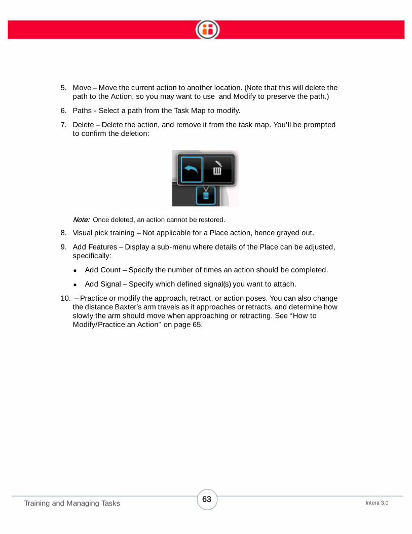
7. Delete – Delete the action, and remove it from the task map. You’ll be prompted
to confirm the deletion:
Note: Once deleted, an action cannot be restored.
8. Visual pick training – Not applicable for a Place action, hence grayed out.
9. Add Features – Display a sub-menu where details of the Place can be adjusted,
specifically:
• Add Count – Specify the number of times an action should be completed.
• Add Signal – Specify which defined signal(s) you want to attach.
10. – Practice or modify the approach, retract, or action poses. You can also change
the distance Baxter’s arm travels as it approaches or retracts, and determine how
slowly the arm should move when approaching or retracting. See “How to
Modify/Practice an Action” on page 65.
63Intera 3.0Training and Managing Tasks
To move a Place location:
1. On the modify screen, click Move. The task map opens with a temporary “ghost”
copy of the location displayed with the move icon over it.
2. Move the arm to drag the ghost to the desired new location.
Tip: Remember to maintain arm pose alignment.
3. Press the action button or OK on the Navigator.
To copy a Place location:
1. On the Modify screen, click Copy. The task map opens with a “temporary ghost”
copy of the location displayed with the copy icon over it.
2. Reposition the arm to drag the copy to the desired location.
Tip: Remember to maintain correct arm pose alignment.
3. Press OK on the cuff to make the copy.
4. Repeat Steps 3 and 4 as many times as needed.
5. When you reach the final Place location, press OK twice. (Alternatively, press Back
.)
64Intera 3.0Training and Managing Tasks

Modifying Count
Actions/action groups and tasks have the following counts by default:
• Pick action – unlimited count
• Place action – count of 1
• Action group (for both Pick and Place) – count of 1 for each location within the
group.
• Task – unlimited count (it resets automatically)
• Sub-task – no count (acts like 1)
You can modify any of these counts, as well as add count to a sub-task.
To modify count to an action:
1. In the Modify screen, click the Add Features icon.
2. Click 123.
3. Select the highlighted box, Max Count.
• If the count is currently unlimited, click the box to un-check it.
• To make the current count unlimited, click the box.
4. On the count wheel, scroll to the first number, and press OK. Repeat for each
number, up to a maximum of 9999.
5. When all numbers are entered, on the screen, press OK.
6. Click Done in the count screen. The new count shows up in the Modify window
next to the Add Features button, as well as for the action on the task map.
How to Modify/Practice an Action
After you have trained an action, you can modify its settings in the Panel.
65Intera 3.0Training and Managing Tasks

1. Select the action on the Task Map.
2. Scroll to the icon and press OK.
66Intera 3.0Training and Managing Tasks

Baxter displays the modify screen.
3. Scroll to the Modify button and press it. Baxter displays the modify action
screen.
67Intera 3.0Training and Managing Tasks

4. Scroll to the approach, action (in this example it’s a Place), or retract point.
Baxter’s arm and hand move to the point as you scroll to it.
5. Grab Baxter’s cuff, adjust the pose and/or location, and press the action button
on the cuff. A check mark is briefly displayed on the screen to register the new
pose/location.
Note: Instead of manually adjusting the pose, you can also choose to more precisely
nudge the pose after selecting the approach, action, or retract point. See “Nudge” on
page 93 for details.
6. Press the back button when done.
You can have Baxter practice the new action by pressing the Practice button.
How to Make Detailed Modifications to an Action (Advanced Settings Screen)
1. From the modify screen (such as in the figure above), press the Advanced button
.
Baxter displays the Advanced Settings Screen.
68Intera 3.0Training and Managing Tasks
2. Make the desired adjustments to the action, described below, and press Done
when complete.
Approach Distance – The distance Baxter’s arm will travel when it approaches its action, for exam-
ple, a Pick. (More technically, this is the point along a vector perpendicular to the position on the
cuff joint from the action’s location that will move into position before moving along the vector to the
action.)
Retract Distance – The distance Baxter’s arm will travel when it retracts from an action, for example,
a Place. (More technically, this is the point along a vector perpendicular to the position on the cuff
joint from the action’s location that will move into position before moving along the vector to the
action.)
Tip: To align an Approach, Action and Retract, change the Approach and Retract values
to 0 and click Done. This aligns the three poses. Now go back to the Advanced Settings
and adjust your Approach and Retract to your desired values.
There may be times when you want the Approach and Retract to move in different
directions. For example, when picking up an object horizontally from a shelf, the
Approach might be parallel to the table while the Retract is perpendicular to the table. In
cases such as this, use modify to adjust the magnitude and direction of Approach and
Retract after setting them to 0.
Go Slow Approach – You can define here a point between the approach pose and the action pose
where the arm slows down so the action will be more precise. (This is also the point where Baxter
turns on contact sensing.) For contact actions (described below), if Baxter feels contact, the arm
will attempt the action.
Go Slow Retract – You can define here a point between the action pose and retract pose where the
arm finishes going slow because it is safely away from performing the action.
Snap to Vertical – Check this box if you want Actions, Approaches, and Retracts that are performed
within 5 degrees of vertical to become truly vertical. (Note that the robot’s Approach, Action, and
Retract poses must be aligned and within 5 degrees of vertical for this function to be enabled.) If
you want to preserve a slightly off-vertical action, make sure this box is unchecked. You can toggle
the checkbox, as long as your pose (Action, Approach or Retract) is within 10 degrees of vertical.
Note: If you’re training a vision-guided Pick, Snap to Vertical must be enabled before you
use the vision system.
69Intera 3.0Training and Managing Tasks

Note: See the tip above, under Retract Distance, to learn how to use the Advanced
Settings Screen to align the Approach, Action and Retract poses.
Action Control Settings – Select here to control when Baxter will perform an action. The options are:
• At Location – The robot will grip or release a part when it arrives at the trained
position -- not when it feels force from an object or achieves a vacuum seal.
• First – The robot will grip or release a part when it either feels contact (if it's using
an Electric Parallel Gripper), when it senses a vacuum seal has been achieved
(Vacuum Cup Gripper), or when it arrives at the trained position, whichever
happens first.
• The robot will only travel 2cm beyond the end point if it doesn’t sense contact
or reach the trained position. This is intentional and is meant to ensure the
robot doesn’t inadvertently collide with other parts of the workspace.
• Contact (Electric Parallel Gripper only) – The robot will grip or release the part
when it feels force from the part or work surface.
• The robot will continue on its approach vector until it comes in contact with a
part and then grasp. This setting is helpful when creating stacks.
• Sensed (Vacuum Gripper, Pick Action only) – The robot will grip the part when it
senses a vacuum seal.
• The robot will continue on its approach vector until it senses a vacuum seal
on the part, and then grasp. This setting is helpful when creating stacks.
• Mixed – When modifying an Action Group, if the Action Group?s individual
locations have a mix of other settings -- for example the first place is Contact and
the second place is At Location -- you will see Mixed as the setting.
Note: You can change Mixed to another setting, but you cannot change another setting to
Mixed. In other words, if you change Mixed to another setting, for example At Location,
all of the actions in that group will Pick At Location, but you cannot change from another
setting to Mixed since you cannot specify which settings will be assigned to which
actions in the group.
70Intera 3.0Training and Managing Tasks

Default Action Control Settings - Pick:
• Electric Parallel Gripper - At Location
• Vacuum Gripper - First
Default Action Control Settings - Place:
• Electric Parallel Gripper - At Location
• Vacuum Gripper - At Location
Drop Height – Define here the height above zero at which Baxter will perform a Place. For vertical
Place actions only. (The zero point on Baxter is where the gray lower front panel meets the black
metal that connects to Baxter’s pedestal.)
Motion Presets - Motion presets define how Baxter’s arm follows a path’s waypoints. “Inherited”
means the preset is inherited from the task level. See “Motion Presets” on page 86.
Note: When you see a "light bulb" symbol on the Advanced screen, that means there is a tip
(or tips) on how to use that functionality. Select the light bulb to display the tip.
Running Tasks
To run a task:
• Click Run in the main button bar.
• Press the Baxter button on the navigator. Click Run.
• Press the Reset button in the main button bar. Reset will reset all counts
everywhere.
Note: If the robot has an object in hand, it will first look to place that object.
Note: When setting a signal, always reset the task before running it.
To stop a task: Touch any navigator or training cuff.
71Intera 3.0Training and Managing Tasks

Create a Path for Baxter
Paths, Waypoints, Poses
There are times when you may want to define the path Baxter’s arm takes when it moves from one
action to another. This is useful for basic machine tending, for example, or to ensure the arm avoids
hitting items in the immediate work area. To accomplish this, you create a path for Baxter. A path is
a series of waypoints or poses of Baxter’s arm.
This illustration shows waypoints along a defined path. In the middle a transit waypoint is highlighted.
Waypoints are poses you create along the arm’s path where Baxter’s arm changes in some way
from its previous or next location. Changes in position and/or orientation of the arm are opportuni-
ties to create waypoints.
72Intera 3.0Create a Path for Baxter

A pose is a position and orientation of Baxter’s arm (shoulder, elbow, hand, wrist, etc.) at a way-
point.
There are also two kinds of paths: default and custom.
A default path is one in which you allow Baxter to create waypoints along the path automatically.
You move the arm from one action to another and Baxter records the waypoints and poses. This is
also called a system-generated path.
You create a custom path when you define the specific waypoints and associated poses along Bax-
ter’s path.
To reduce clutter, only custom paths are displayed on the Task Map, unless you are in Path Mode
(accessed when you select the Paths button on an action’s modify panel).
How to Create a Custom Path for Baxter
To illustrate this feature, we will create a Pick and a Place with a user-defined, or custom path.
1. Create a Pick for an object.
2. With the object in hand, press the Action Button (the round button on the cuff).
Baxter displays the action bar.
3. Scroll to the Path icon to highlight it, then press OK on the Navigator.
4. Elevate the arm above the location of the Pick, pose the arm and hand as
desired, and press the Action Button to train the first waypoint/retract point.
Because you’re creating a custom path, this first waypoint will become the Pick’s
Retract point. A Retract point is the location and pose to which Baxter will return
after an Action. (This is also the location where the “Go Slow” command ends
and normal speed resumes. See “How to Make Detailed Modifications to an
Action (Advanced)” on page 60.)
A “path mode” crosshair indicates on the Task Map the location of the Retract point.
73Intera 3.0Create a Path for Baxter

5. Move Baxter’s arm to the next waypoint, keeping in mind the position of the arm
and hand as you move it along the path. Press the action button to establish
another waypoint.
6. Continue creating the desired path by moving Baxter’s arm and hand and
pressing the action button on the cuff to create a series of waypoints.
The last waypoint you create before the Place action (in this example) will be automatically set as
the Approach point. The Approach point is the location and pose of the hand in anticipation of an
action--in this example, the point at which Baxter’s arm will begin moving toward the Place location.
On the Task Map, Approach and Retract points are orange.
Transit points are points along the path not associated with an action. They are locations that guide
Baxter’s arm along a path. Transit points on the Task Map are displayed in yellow.
The waypoint closest to the Pick or Place automatically becomes the Approach or Retract point.
Keep in mind that Baxter moves in curved Joint Coordinates along transit waypoints, but in straight
Cartesian Coordinates between the Pick or Place and the Approach and Retract points. This is
important when Baxter needs to move along a straight line in the direction of the gripper, such as
when placing an object into a box or assembling two components. However, while the transit way-
point poses are approximated as Baxter moves along the path, Pick, Place, and Hold poses are
precise.
74Intera 3.0Create a Path for Baxter
7. Create the Place by pressing the Grasp button.
8. You can now select Run from the Task Map button bar to run the Pick and Place
task.
USAGE NOTES FOR CREATING A PATH:
• When you create a path, Baxter remembers the orientation and angle of each
joint in its arm and the coordinates of its wrist for all the waypoints except for the
Approach and Retract points.
• If, when training Baxter, you need to put an object in the gripper and you don’t
want to create a new action, double-click the grasp button. Baxter will grab the
object without creating a new action.
• If you press the Back button while creating a path, all waypoints in that path are
deleted.
• When you run a task, notice that the arm rewinds along the path you created
when it returns to the Pick location.
• You can add a custom (user-defined) path between poses by modifying and
retraining a path. That path will show up on the Task Map. To do this, modify a
pose, select the Paths icon in the Modify Path panel, then select the action where
the path leads.
Best Practices: Creating Waypoints
• It is not necessary -- or even desirable -- to define a large number of waypoints
when training a path. The more transit points you add, the longer the path and
therefore, the more time the task will take to run.
• If you train a number of waypoints relatively close together along a path, Baxter's
arm movement will become jerky.
• Train just those points needed to avoid obstacles that may be in Baxter's path.
How to Practice a Path
1. Select an action on the Task Map and press OK on the Navigator.
Baxter displays the Modify Panel for the action.
75Intera 3.0Create a Path for Baxter

2. Select the Path icon in the Modify widow and press OK on the Navigator.
Baxter displays the Task Map with the action and its path.
76Intera 3.0Create a Path for Baxter

3. On the task map, select the path your want to practice.
Baxter displays the Panel for the selected path.
In the illustration, the orange waypoints represent retract and approach points. Yellow points are
transit points, the points between the Pick and the Place. The approach pose for the Pick is high-
lighted.
4. Press the Practice button.
5. Select to practice the path at either slow or full speed. (Slow speed is equal to
approximately one-half full speed.)
Baxter practices the path.
Note: You can grab the cuff while Baxter is in practice mode to stop the arm from moving. That
does not alter the waypoints in the path or any of the poses associated with the path.
How to Modify a Waypoint
Note: See “Nudge” on page 93 for details on making precise changes to Baxter’s arm
and gripper location and orientation.
77Intera 3.0Create a Path for Baxter
1. Select the path you want to modify on the Task Map and press OK on the Navi-
gator.
2. Baxter displays the Modify Transit Panel for that path.
3. Press the Modify button.
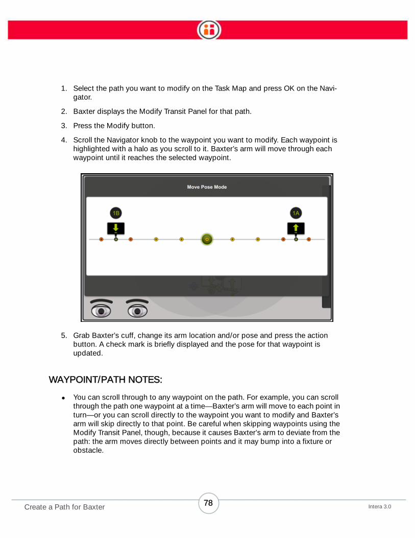
4. Scroll the Navigator knob to the waypoint you want to modify. Each waypoint is
highlighted with a halo as you scroll to it. Baxter’s arm will move through each
waypoint until it reaches the selected waypoint.
5. Grab Baxter’s cuff, change its arm location and/or pose and press the action
button. A check mark is briefly displayed and the pose for that waypoint is
updated.
WAYPOINT/PATH NOTES:
• You can scroll through to any waypoint on the path. For example, you can scroll
through the path one waypoint at a time—Baxter’s arm will move to each point in
turn—or you can scroll directly to the waypoint you want to modify and Baxter’s
arm will skip directly to that point. Be careful when skipping waypoints using the
Modify Transit Panel, though, because it causes Baxter’s arm to deviate from the
path: the arm moves directly between points and it may bump into a fixture or
obstacle.
78Intera 3.0Create a Path for Baxter

• You cannot nudge (See “Nudge” on page 93) a transit waypoint.
• When you see a "light bulb" symbol on a Modify Waypoint screen, that means there is a
tip (or tips) on how to use that functionality. Select the light bulb to display the tip.
How to Modify a Path (includes Practice and Retrain)
1. With a task already created, select the action where the path originates. For
example, if the path is from a Pick to a Place, scroll to the Pick.
79Intera 3.0Create a Path for Baxter

2. Press OK and select the Paths icon from the Modify screen.
Baxter displays the Task Map.
80Intera 3.0Create a Path for Baxter

3. From the Task Map, scroll through the possible paths, and press OK on the one
you want to change.
Baxter displays the screen. From there you can choose to practice, modify, or retrain the path.
PRACTICE
Practice gives you a run-through of the path as it exists now. You can practice at two different
speeds: slow and full.
RETRAIN
Retrain enables you to quickly modify an existing path. Pressing Retrain deletes the transit way-
points on the current path, while keeping the pick and place actions and their associated approach
81Intera 3.0Create a Path for Baxter
and retract points. (You can then add new waypoints to the path.) Retrain is also an option in the
Modify Panel submenu for selected waypoints.
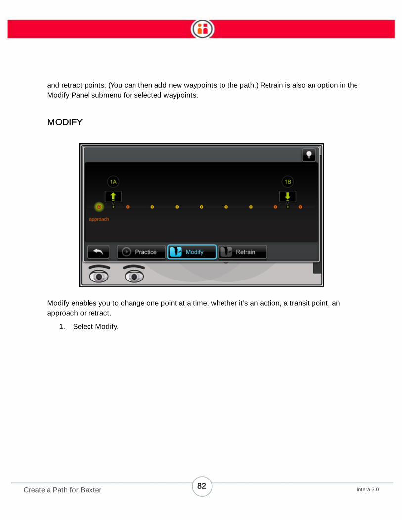
MODIFY
Modify enables you to change one point at a time, whether it’s an action, a transit point, an
approach or retract.
1. Select Modify.
82Intera 3.0Create a Path for Baxter

Baxter displays the modify path panel, in Move Pose Mode.
Selecting a waypoint displays different submenus depending on the kind of waypoint selected and
the kind of action upon which the path is based.
83Intera 3.0Create a Path for Baxter
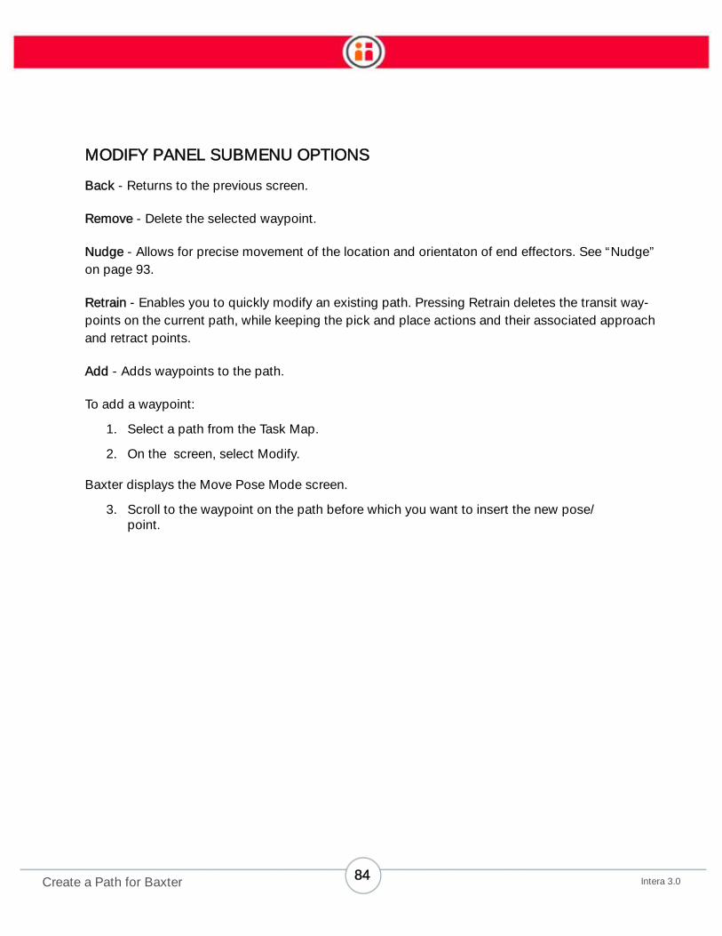
MODIFY PANEL SUBMENU OPTIONS
Back - Returns to the previous screen.
Remove - Delete the selected waypoint.
Nudge - Allows for precise movement of the location and orientaton of end effectors. See “Nudge”
on page 93.
Retrain - Enables you to quickly modify an existing path. Pressing Retrain deletes the transit way-
points on the current path, while keeping the pick and place actions and their associated approach
and retract points.
Add - Adds waypoints to the path.
To add a waypoint:
1. Select a path from the Task Map.
2. On the screen, select Modify.
Baxter displays the Move Pose Mode screen.
3. Scroll to the waypoint on the path before which you want to insert the new pose/
point.
84Intera 3.0Create a Path for Baxter
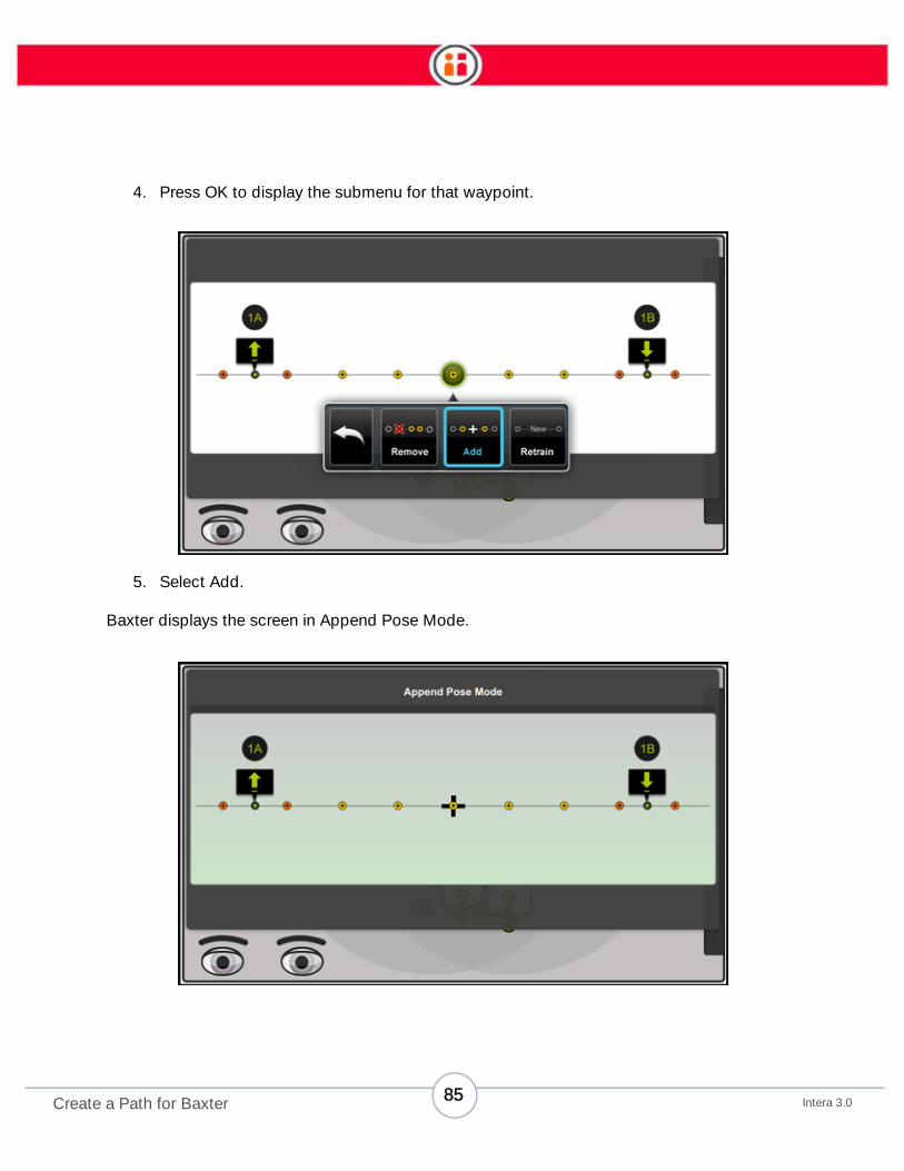
4. Press OK to display the submenu for that waypoint.
5. Select Add.
Baxter displays the screen in Append Pose Mode.
85Intera 3.0Create a Path for Baxter
6. Manually position Baxter’s arm and end effectors in the pose you want to add.
7. Press the round action button on the training cuff to set the new pose.
8. Repeat for each new waypoint. Changes are saved automatically.
9. When done, press the Back button.
Suggestion: Use Practice to run through the path to check the new pose.
NOTE: You may find that some locations or poses will be invalid. That means the location or pose
cannot be performed by Baxter because it’s near a joint limit. On the Task Map this would show up
as a grayed out icon. On the screen, Baxter displays the message, “Add pose failed.”
Motion Presets
Motion presets define how Baxter's arm follows a path's waypoints. These presets will help Baxter
complete a wider variety of tasks.
There are three types of presets:
• Balanced - The default preset. This is the way Baxter has followed waypoints
along its path in the past. (If you upgrade a task from a previous version of the
software, this is the preset that will be selected.)
• Explicit - Baxter will follow the waypoints closely, and in a controlled manner (that
is, more closely and controlled than either the Balanced or Express presets.) This
preset would be a good choice for machine tending tasks.
• Express - Baxter will use the path's waypoints more as a guide to follow rather
than as a specific target to hit. With this preset, Baxter is optimized to complete
its actions faster than the other presets. Use this preset when cycle time is
paramount and repeatability or precision is not critical.
You set presets at the task level, as you do for signals, counts, and advanced settings, but you also
have the option of overriding the preset at the action level (i.e., pick, place, or hold).
How to Change Motion Presets at the Task/Arm Level
1. From the Task Order screen, highlight the task for either arm.
2. Select the add button and press OK to display the task bar
buttons.
86Intera 3.0Create a Path for Baxter

3. Select the Motion presets icon .
4. Scroll through the motion presets options and select a preset.
5. Press OK.
How to Change the Motion Preset at the Action Level
1. Highlight the pick, place, or hold action on the Task Map and press OK.
2. On the modify action screen, select the icon.
3. Select the Advanced icon on the modify screen to display the advanced
action modification screen.
The default setting for the action is "Inherited." That means the setting is the same as, or inherited,
from the task level.
87Intera 3.0Create a Path for Baxter

4. Change the motion preset for the individual action by selecting the Motion
Presets icon.
5. Scroll through the options.
6. Press OK to select one of the presets, then press Done to save it.
IMPORTANT NOTE ABOUT MOTION PRESETS
The destination action -- the action to which the arm is moving along the path -- is where you apply
the motion preset. For example, if you need Baxter's arm to move in a controlled, deliberate fashion
from a hold to a pick, you would choose Explicit as the motion preset and assign it to the pick
action.
88Intera 3.0Create a Path for Baxter

Hold
Baxter can hold an arm in position for a period of time or until a signal is triggered. This feature is
useful for such jobs as holding an object in Place for inspection, scanning, labeling, painting, etc. It
can also be used when you want to move an arm to a neutral location to wait for machine cycling,
or for a process to be finished.
If you want to add a signal so Baxter will move after a hold, specify as long a time as possible for
the hold or Baxter will move when the time is up and not wait for the signal.
Hold works with or without a part being grasped, and in any pose or orientation. However, Hold
does need to be part of a task that has a Pick and Place action.
Note: Hold is not a waypoint and Baxter does not treat it as such. Rather, Hold is an
action that takes Place in a specific location.
How to Train Baxter to Perform a Hold
To illustrate this feature, we’ll create a new task in which Baxter will hold up a part to be scanned.
1. Create a new task.
2. Create a Pick by grasping an object.
3. Position Baxter’s arm and hand in the location and orientation you want it to hold,
e.g., in front of a scanner.
4. Press the action button (the round button on the training cuff) to display the
action bar.
89Intera 3.0Hold
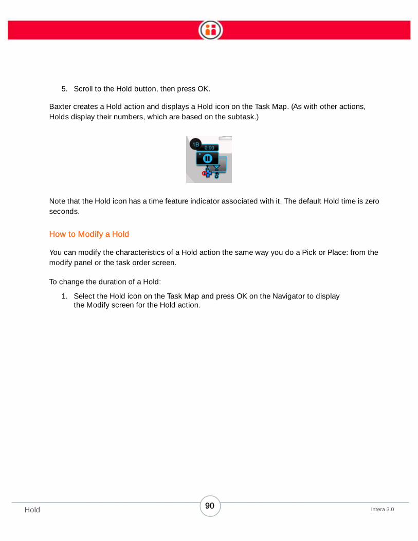
5. Scroll to the Hold button, then press OK.
Baxter creates a Hold action and displays a Hold icon on the Task Map. (As with other actions,
Holds display their numbers, which are based on the subtask.)
Note that the Hold icon has a time feature indicator associated with it. The default Hold time is zero
seconds.
How to Modify a Hold
You can modify the characteristics of a Hold action the same way you do a Pick or Place: from the
modify panel or the task order screen.
To change the duration of a Hold:
1. Select the Hold icon on the Task Map and press OK on the Navigator to display
the Modify screen for the Hold action.
90Intera 3.0Hold
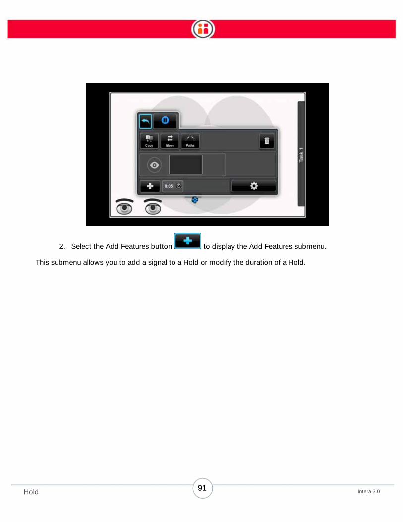
2. Select the Add Features button to display the Add Features submenu.
This submenu allows you to add a signal to a Hold or modify the duration of a Hold.
91Intera 3.0Hold

3. Select the Time icon to display the Time panel.
4. Select the spin box then scroll through to change time for the Hold.
The maximum amount of time is 30 minutes.
You can also attach signals to a hold. If a signal and timer are attached, whichever comes first will
prompt Baxter to continue movement.
92Intera 3.0Hold
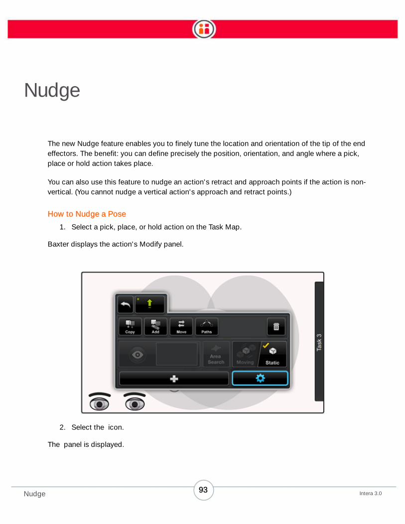
Nudge
The new Nudge feature enables you to finely tune the location and orientation of the tip of the end
effectors. The benefit: you can define precisely the position, orientation, and angle where a pick,
place or hold action takes place.
You can also use this feature to nudge an action's retract and approach points if the action is non-
vertical. (You cannot nudge a vertical action's approach and retract points.)
How to Nudge a Pose
1. Select a pick, place, or hold action on the Task Map.
Baxter displays the action's Modify panel.
2. Select the icon.
The panel is displayed.
93Intera 3.0Nudge
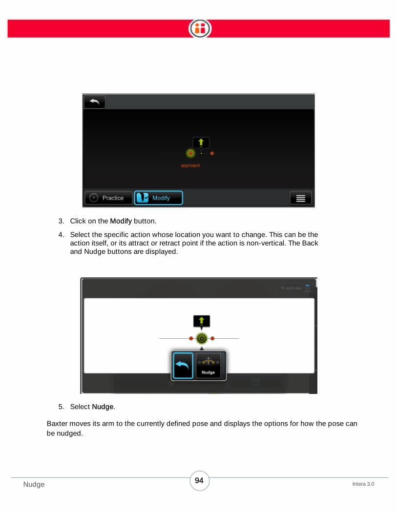
3. Click on the Modify button.
4. Select the specific action whose location you want to change. This can be the
action itself, or its attract or retract point if the action is non-vertical. The Back
and Nudge buttons are displayed.
5. Select Nudge.
Baxter moves its arm to the currently defined pose and displays the options for how the pose can
be nudged.
94Intera 3.0Nudge

NOTE: Pay close attention to the icons on the Nudge screen, specifically the cuff’s profile in the dis-
play images compared to that of the cuff on your robot. Use the location and orientation of the
cuff’s camera as a reference point.
Training cuff profile: camera on right
Training cuff profile: camera in back
In short, when you nudge Baxter's cuff, make sure the profile of the robot matches the image
shown in the display.
YAW, PITCH, AND ROLL
Yaw, pitch, and roll are terms used to describe the way in which an airplane moves about its three
axes.
• Yaw - twist or oscillate (nose left or right) about the vertical axis running up and
down the plane.
• Pitch - move nose up or down about the axis running from wing to wing.
95Intera 3.0Nudge

• Roll - rotate about the axis running from nose to tail.
It is helpful to keep these terms in mind when using the bottom row options (on the next page) in
Nudge. Just picture the orientaton of Baxter’s wrist as below and equate this orientation with the
nose of an airplane. In other words, picture the front view of wrist, with the gripper fingers pointed at
you and the camera on the bottom, as being the nose of the airplane. Then yaw, pitch or roll
accordingly.
Side view Front view
96Intera 3.0Nudge

(Top row) You can nudge the arm in millimeter increments along the X, Y, Z axes of the cuff (called
a translation change) specifically:
• along the x axis: in a line from the gripper connector to cuff camera
• along the y axis: left and right, perpendicular to the cuff camera
• along the z axis: up and down
(Bottom row) You can nudge the angle of the wrist around the X, Y, and Z axes in fractions of
degrees (0.25), specifically:
• yaw the wrist
• pitch the wrist
• roll (rotate) the training cuff
97Intera 3.0Nudge
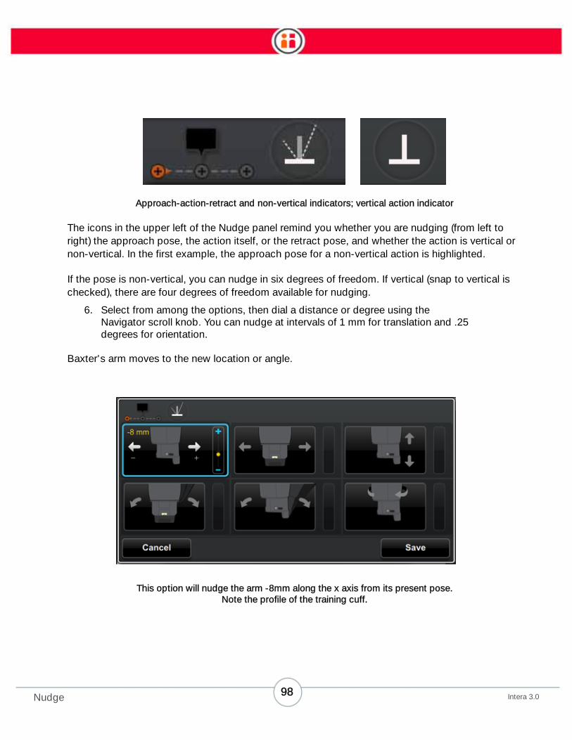
Approach-action-retract and non-vertical indicators; vertical action indicator
The icons in the upper left of the Nudge panel remind you whether you are nudging (from left to
right) the approach pose, the action itself, or the retract pose, and whether the action is vertical or
non-vertical. In the first example, the approach pose for a non-vertical action is highlighted.
If the pose is non-vertical, you can nudge in six degrees of freedom. If vertical (snap to vertical is
checked), there are four degrees of freedom available for nudging.
6. Select from among the options, then dial a distance or degree using the
Navigator scroll knob. You can nudge at intervals of 1 mm for translation and .25
degrees for orientation.
Baxter's arm moves to the new location or angle.
This option will nudge the arm -8mm along the x axis from its present pose.
Note the profile of the training cuff.
98Intera 3.0Nudge

This option will nudge the lower portion of the arm 3.75 degrees
away (along the z axis) from Baxter.
7. To save the new pose, press OK.
Note: You can make multiple nudges to Baxter's arm, both along and around the XYZ axes, by
pressing OK after each Nudge.
8. When done, press the Save button.
NOTES ON NUDGE
• If you are nudging a vertical pose, you cannot nudge the angle of the training
cuff. The first two options in the bottom row are grayed out. This helps ensure the
vertical pose does not change to a non-vertical pose.
• You should move the arm before you enter Nudge mode. While in Nudge mode,
you can move the arm by squeezing the training cuff and moving the arm as you
normally would in zero gravity. If you press the Save button after moving the arm,
this becomes the updated pose from which nudges are made.
• Keep in mind that, if you nudge an Action, its Retract and Approach are not nudged proportionally. This is true for any Nudge, including Holds with a zero
Approach/Retract distance. So, in the case of the Hold, if you nudge, make sure
you go to the advanced menu and make the Approaches/Retracts zero distance.
• Pressing the Action button after manually moving the arm to a new pose does
NOT save the pose.
99Intera 3.0Nudge

• You cannot nudge transit points.
You can use the Navigator on either arm when in Nudge mode.
100Intera 3.0Nudge

Lock/Unlock
You can lock and unlock Baxter using a password stored on a USB stick.
This feature helps prevent unauthorized personnel from tampering with the tasks stored on the
robot. If the robot is locked, users can only run, reset, clear errors/confusion, or power cycle (acti-
vate/deactivate Sleep) on the robot. When Baxter is locked, tasks cannot be created, modified or
changed.
If the robot is unlocked, users have access to all of the robot's features, tasks, etc.
This feature requires a USB device, formatted FAT32, with a text file with the name, RethinkPass-
word.txt. Baxter will recognize this .txt file only if it resides on the USB device's root directory.
You can create your own text file with this character string or download it directly from the Rethink
Robotics FTP site.
Note: The password file will then be provided by the Rethink Robotics Support team via Rethink's
FTP site.
How to Lock or Unlock Baxter
1. Insert the USB device containing the RethinkPassword.txt into the USB port on
the back of Baxter. If not inserted, the lock/unlock option will look like this:
101Intera 3.0Lock/Unlock

2. Once the stick is inserted, from Baxter's button bar, select Sleep.
3. Select Lock or Unlock, depending on what state you want Baxter to be in.
102Intera 3.0Lock/Unlock

Signals
Working with Signals
Baxter can send (out) or receive (in) digital (on/off, true/false, yes/no) signals from other machines. It
has two built-in signal ports on its DB15 connector, one In and one Out. You can attach and
configure additional devices via the robot’s Ethernet port.
To set up signals, first attach and configure the device (see “Appendix C: Configuring External
Devices” on page 129); then, add a signal to a task, create the signal, and attach it.
To make it easier for you to track, Baxter sends and recognizes the following signals.
Note: Unless otherwise noted, level signals are active when true; edge signals look for
false-to-true transitions.
• In Ready (level and edge) – Signals to Baxter that the external world is ready for it
to perform an action. In some cases, the In Ready signal also tells Baxter to reset
counts.
• In Error (level) – Signals to Baxter that an external machine or device has an error.
Baxter stops and waits until In Error becomes false before resuming where it left
off.
103Intera 3.0Signals

• In Continue (level) - For sub-tasks, signals that the task should continue to the
next sub-task. This signal is only considered when a sub-task is between action
sequences. For Hold actions, causes the hold action to terminate immediately
instead of waiting until the time interval has elapsed.
• Reset In - Baxter can receive a Reset In Signal if a PLC triggers Baxter to reset its
task to start at the first action. This is essentially the same as stopping Baxter
and pressing the reset button. Returns all counts to 0.
• Out Done (level) - This signals that Baxter is done with an action, sub-task or
task, i.e., that the count is complete. This signal may stay true for an arbitrary
length of time, but never less than 0.5 seconds.
• Out Count (edge) - Signals that Baxter has executed an action that has changed
a count.
• Out Error (level) - Signals that Baxter has a problem and has stopped executing
the task.
• Out Confusion (level) - Signals that Baxter may need materials or help. User
intervention is likely required.
• Out Action Ended (edge) - Signals that Baxter has finished an action, i.e., that the
arm has reached the action's retract point.
• Out Action Started (edge) - Signals that Baxter is starting on an action, i.e., that
the arm has reached the action's approach point.
• Reset Out - Baxter can send a Reset Out Signal to reset a PLC when the user
presses “Reset” in Baxter’s UI. Returns all counts to 0.
104Intera 3.0Signals

From the Task Map, press the Baxter button, and click I/O to access the signals gallery. Use this
screen to view available signals, or add new ones.
When you first access the signals gallery, it will be blank, as in the illustration above, if no signals
have been created yet.
If signals do exist in the gallery, the display will be similar to the one below.
105Intera 3.0Signals

1. Create signal – Add a signal to the gallery.
2. Displays a list of all signals defined for the current task.
3. Displays the details of the selected signal.
• Name of the signal
• Device name and line number
• Number of places the signal is added to the task
• Number of the type (e.g., In Ready) of signals created
1
2 3
106Intera 3.0Signals

Creating Signals
To create a signal and store it in the signal gallery:
1. In the task gallery, click the create signal icon.
2. In the add signal screen click the type of signal. “In” signal icons feature a right-
and-down pointing arrow (first row, below); “out” signals all have a left-and-up
pointing arrow (second and third rows).
In the configure signal screen, change the name if it is not clear to your team;
then reference the correct device, and the line number.
3. When complete, click Done. You can later return to modify any of these details.
107Intera 3.0Signals

Invert Signals
You can easily invert the signals Baxter sends or receives by clicking on the invert icon:
108Intera 3.0Signals

Attaching Signals
You can attach signals to actions, action groups, sub-tasks, or to entire tasks.
• For an action or action group, click Add Features in the Modify screen.
• For a task or sub-task, select the task or sub-task in the task order screen, and in
the task order button bar, click the signals icon.
To attach a signal:
1. Select the checkbox to the left of the signal type.
2. Select the signal name (if more than one of this type); scroll to the signal name,
and press OK to scroll through the available signal names. Press OK to attach the
signal.
3. Optionally, if selecting an In Ready signal, select whether you want it to reset
count every time the signal occurs.
Tip: By default, the robot does not reset count for Pick actions. This means that Baxter
can continue picking items even if a Place action count is reset. Choose this option if you
want the count to reset every time, whether or not there are Picks still available.
4. When finished, click the Back icon on the screen.
109Intera 3.0Signals

SIGNALS: NOTE
• As of Intera 3.0, you can now assign any valid signal to Baxter’s Torso’s Input or
Output port. You are no longer limited to using only Ready or Done for these two
ports.
110Intera 3.0Signals

Maintaining and Supporting Baxter
Powering Down Baxter
1. Clear the area around the robot.
2. If performing maintenance, grab the training cuff or turn the knob to cause the
head to move to the side. (Pressing the Navigator button may run or reset a task,
so it’s safer and simpler to grab the cuff or turn the knob.) Moving the head to the
side makes it easier to remove the front cover. If the robot does not have power,
carefully move the head manually.
3. Press the white power button on the robot pedestal.
The shutdown process is complete when the green and yellow lights around the
head shut off.
Unplug the power cord from the wall outlet/power source.
Maintaining Baxter
Cleaning Baxter
To clean Baxter, periodically wipe it down with a clean, damp cloth.
Replacing the Air Filters
Check the Baxter air filters at least every six months, and replace them as necessary. Baxter has
two air filters, one on each side of the torso.
• To remove a filter, use a 2 mm hex key to remove the two screws from the air
filter; remove the filter.
• To install a filter, use a 2 mm hex key to install the two screws and attach the filter
to the side of the torso.
111Intera 3.0Maintaining and Supporting Baxter

Upgrading Software
IMPORTANT Upgrading software for some releases overwrites all programs in system memory,
including all previously trained tasks. (This is true for some releases. It is not true when upgrading
from 2.1 or 2.1.1 to 3.0.)
1. On Baxter, go to Main Screen > Settings > Advanced > Update Software.
2. Insert the USB device that includes the software upgrade, and wait for Baxter to
recognize the device.
3. Select the version of software you want to install.
4. Select Yes Continue in the confirmation dialog.
A status screen appears as the software loads.
5. When the software finishes installing, restart Baxter.
Supporting Baxter
Occasionally, Baxter encounters problems that can inhibit its ability to perform tasks. This section
describes the types of problems that may occur, and the actions you can take to resolve them.
Typically you will be able to solve the problem yourself. In some cases, however, you may need to
contact your technical support representative for assistance.
112Intera 3.0Maintaining and Supporting Baxter
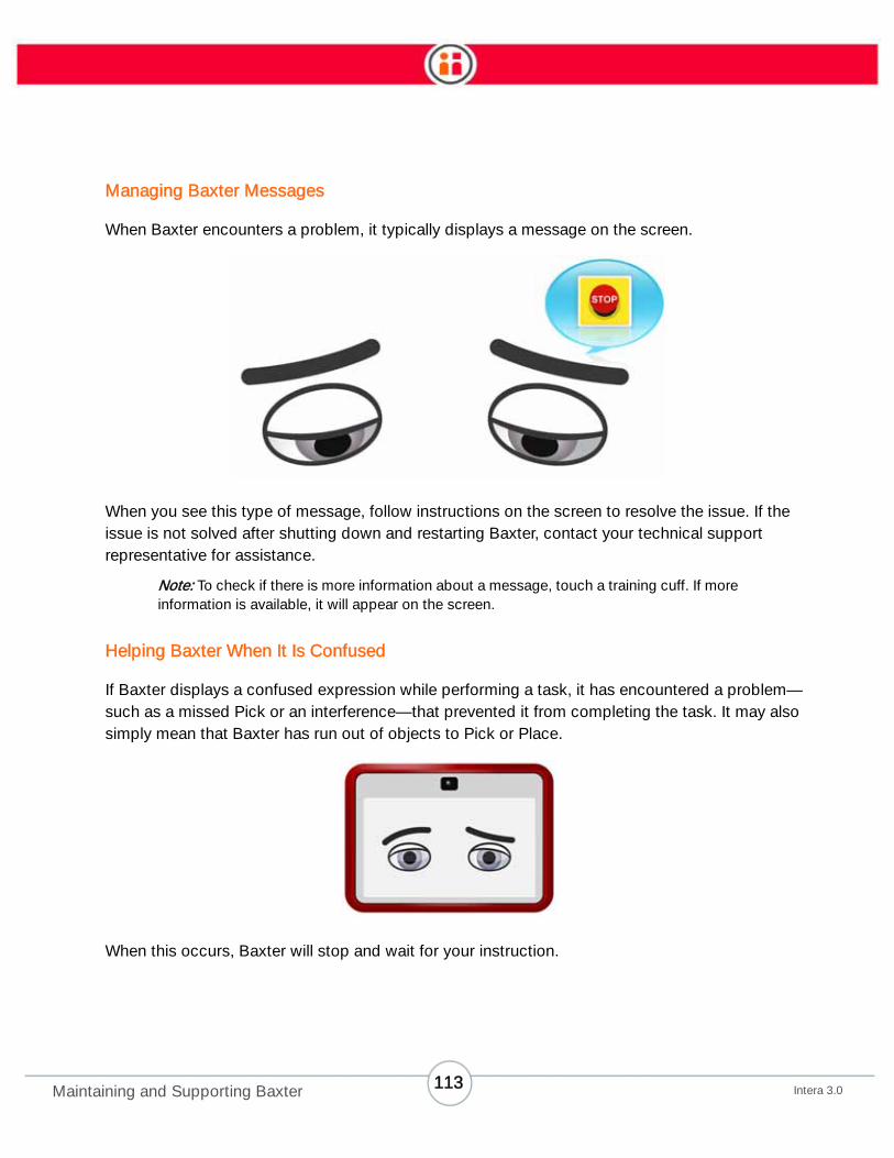
Managing Baxter Messages
When Baxter encounters a problem, it typically displays a message on the screen.
When you see this type of message, follow instructions on the screen to resolve the issue. If the
issue is not solved after shutting down and restarting Baxter, contact your technical support
representative for assistance.
Note: To check if there is more information about a message, touch a training cuff. If more
information is available, it will appear on the screen.
Helping Baxter When It Is Confused
If Baxter displays a confused expression while performing a task, it has encountered a problem—
such as a missed Pick or an interference—that prevented it from completing the task. It may also
simply mean that Baxter has run out of objects to Pick or Place.
When this occurs, Baxter will stop and wait for your instruction.
113Intera 3.0Maintaining and Supporting Baxter

Calibrating the Arms
Calibrate the arms to troubleshoot common error messages, and to help Baxter maintain its peak
performance. It is also recommended that calibration is performed according to the following
schedule:
• Weekly – perform a Basic calibration on both arms.
• Monthly and whenever the robot is shipped – perform a Factory and Spring
calibration on both arms.
IMPORTANT During calibration, Baxter arms must be able to move freely in all directions, starting
from the base of the robot on up.
IMPORTANT During calibration, Baxter force sensing is turned off. Before calibrating the arms,
remove the grippers, and make sure the workspace is clear above the base of the robot. (Baxter's
arms calibrate above the work surface.) If it is not possible to clear the workspace, move Baxter
away from the workspace, and clear a 5-foot radius around the robot. While calibration is active, it
is important to maintain a distance outside of this 5-foot radius.
If one (or both) of the Baxter arms begins to lose pick and place accuracy while performing trained
tasks, try calibrating the arm(s) to fix the problem. Baxter offers three types of arm calibration:
• Basic – performs a basic calibration on the arm or arms selected; use as a first
step in fixing the problem. The process takes approximately 15 seconds per arm.
• Factory – performs a thorough calibration of all joints on the arm or arms
selected; use if spring calibration does not fix the problem. This process takes
approximately 7 minutes 20 seconds per arm.
Note: Always follow up a Factory calibration with a Spring calibration.
• Spring – performs a shoulder calibration on the arm or arms selected; use if basic
calibration does not correct the problem. The process takes approximately 3
minutes 20 seconds per arm.
114Intera 3.0Maintaining and Supporting Baxter

To calibrate an arm:
1. Make sure there is a clear, 5-foot radius around and above the base of the robot.
If Baxter is attached to a pedestal, and it is not possible to clear the workspace
around the robot:
• Mark the current location of Baxter by drawing on or affixing tape to the floor
near the edges or corners of the pedestal. (This action will help to re-position
Baxter after moving it for calibration.)
• Roll Baxter on its pedestal, away from the workspace and into an area large
enough for the arms to move freely.
2. Make sure Baxter is level.
3. Scroll to Main Screen > Settings > Hardware Settings > Calibrate Arms; then
select a form of calibration (Basic, Factory, or Spring).
4. Select one or both arms; then press OK to begin the calibration.
5. Move away from the robot, and make sure all persons are clear of Baxter.
The selected arm moves as follows for each type of calibration:
• Basic – the arm drops to the side of the robot, then rises up and extends
outward.
• Factory – the arm moves to the side of the robot, then rises up and extends
outward in a few different directions.
• Spring – the arm moves to the side of the robot with the elbow at the lowest
point, then rises up and extends outward.
115Intera 3.0Maintaining and Supporting Baxter

6. When the robot finishes calibrating, if a Factory calibration was performed:
a. Reboot the robot.
b. Scroll to Main Screen > Settings > Hardware Settings > Calibrate Arms, and
select Spring Calibration.
Wait for the robot to complete the Spring calibration.
7. Return Baxter to its workspace (if moved).
8. If the grippers were removed, reinstall them.
9. Restart the robot.
10. If the grippers were removed and reinstalled, configure and train each gripper.
If after calibration, Baxter still does not function correctly, try retraining and running the task. If the
problem is not solved, contact your technical support representative.
Troubleshooting Baxter
To troubleshoot Baxter:
• If Baxter isn’t behaving as expected, restart the robot, then try running the task
again.
• If Baxter is having trouble accurately picking and placing objects, try calibrating
the arms (see “Calibrating the Arms” on page 114 for instructions).
If this does not solve the problem, please consult the knowledge base in the Rethink Robotics
customer support portal. If the problem persists, contact your authorized Rethink Robotics service
provider for technical support.
116Intera 3.0Maintaining and Supporting Baxter

Exporting Log Files
Baxter logs its daily activity and saves it into files. When an unidentified problem occurs with the
robot, your technical support representative may ask you to export log files to a FAT 32 USB device,
download them to a PC, and upload the files to Rethink Robotics support. The files may help them
to troubleshoot and fix the problem.
To export a log file:
1. Touch one of the four navigator buttons on the robot to open the button bar.
2. Select Setting > Advanced > Diagnostics.
3. Insert a formatted FAT 32 USB device into Baxter. Make sure there is at least 2
GB of available space on the device.
4. Select Export Logs to USB > Export.
The log files copy to the USB device.
To retrieve the files from the USB device and email them to Rethink Robotics, insert the USB device
into a PC, copy the files from the device to the PC, then attach the files to an email message, and
send the message to the requester.
Enjoy!
This concludes the core content of the Baxter User Guide. Please refer regularly to our customer
support portal, located here:
http://www.rethinkrobotics.com/index.php/support/
The portal includes the latest product information, technical documentation, and additional support
guides.
On behalf of the entire team at Rethink Robotics, we wish you great success with your Baxter robot,
and hope you find it to be a valuable solution for your business.
Several appendices follow, with more detailed examples of information contained in this document.
117Intera 3.0Maintaining and Supporting Baxter

Appendix A: Configuring Grippers
When you attach a gripper, Baxter automatically detects the gripper type, and prompts you to
configure it. Configuration teaches Baxter:
• Finger type, finger tips, and finger position of a parallel gripper
• Extension(s) and vacuum cup size of a vacuum gripper
If you change any component of a gripper (such as adding extensions to a vacuum cup) without
detaching it, go to Settings > Hardware Settings > Configure End Effectors to reconfigure it. If you
do not do this, Baxter may have trouble picking up or holding on to objects.
Configuring an Electric Parallel Gripper
Using the navigator on the arm with the gripper you want to configure:
1. If not already open, scroll to Main Screen > Settings > Hardware Settings >
Configure End Effectors.
2. If you need to install or adjust the gripper, depending on where you are standing,
click Behind or Front. Baxter automatically presents its hand to you, either in
front, or off to the side in back.
Note: You can also manually move the arm to access the gripper.
3. Select the correct Fingers type. (For custom fingers, see “Appendix C: Set
Length, Weight of Custom Vacuum Gripper***” on page 122.)
4. Optionally, select the Finger Tip type.
Tip: The Baxter Finger Tips are imprinted with their type.
118Intera 3.0

5. Select the appropriate finger Position.
6. Optionally, click Calibrate before final training. Baxter automatically opens/closes
the gripper to test its grasp dimension.
7. Click Train. The gripper rotates as Baxter learns it.
Custom Finger Tips
If you are using custom finger tips, select Custom as the Finger tip type.
119Intera 3.0
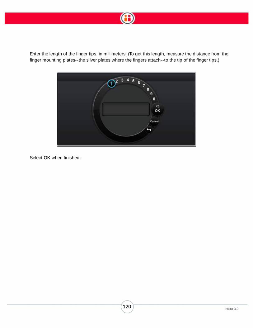
Enter the length of the finger tips, in millimeters. (To get this length, measure the distance from the
finger mounting plates--the silver plates where the fingers attach--to the tip of the finger tips.)
Select OK when finished.
120Intera 3.0
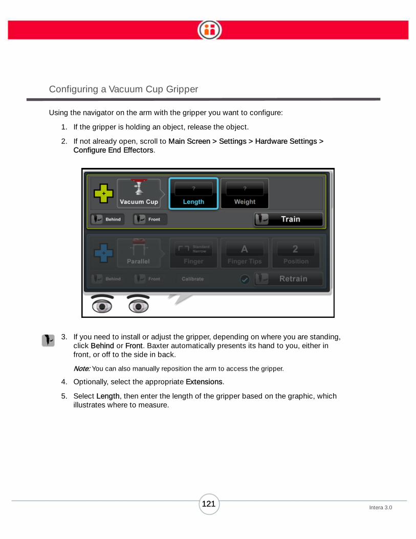
Configuring a Vacuum Cup Gripper
Using the navigator on the arm with the gripper you want to configure:
1. If the gripper is holding an object, release the object.
2. If not already open, scroll to Main Screen > Settings > Hardware Settings >
Configure End Effectors.
3. If you need to install or adjust the gripper, depending on where you are standing,
click Behind or Front. Baxter automatically presents its hand to you, either in
front, or off to the side in back.
Note: You can also manually reposition the arm to access the gripper.
4. Optionally, select the appropriate Extensions.
5. Select Length, then enter the length of the gripper based on the graphic, which
illustrates where to measure.
121Intera 3.0

6. Click Done, then select the vacuum cup’s Weight icon.
7. Enter the weight of the gripper and click Done.
8. Click Train. The gripper rotates as Baxter learns it.
Custom Extensions
If the gripper has custom extensions, select Extensions > Custom.
122Intera 3.0

Enter the length of the extensions in millimeters and the weight in kilograms. Press Done when fin-
ished.
123Intera 3.0
Appendix B: Specify Object and
Custom Gripper Weights
To achieve optimized arm performance, you can specify the weight of the object Baxter will handle
as well as the weight of custom grippers you may use. This feature makes Baxter capable of recog-
nizing weight – and adjusting to it – so arm movements will be smoother and more efficient. For
instance, if you input a payload of three pounds (1.4 kg) for the gripper weight, Baxter will recognize
that weight, so when you squeeze the training cuff to move Baxter’s arm, it will feel essentially
weightless and performance may also improve. (Note, however, that if you adjust the weight of a
custom gripper and do not specify that change, Baxter’s arm performance will likely suffer.)
Baxter can support up to five pounds (2.2 kg) on each of its s. An is made up of the plate and its
attachments (electronic gripper or vacuum, fingers).
NOTE: The five-pound limit includes both the weight of the objects Baxter will be handling and the
weight of the itself, so keep that in mind when specifying total gripper weight.
How to Specify Object Weight
1. Select a Pick action or Pick action group on the Task Map and press OK on the
Navigator to display the Modify Task Window.
124Intera 3.0

2. Scroll to the Add Features button and press OK to display the task button bar.
3. Highlight the Weight icon and press OK to display the weight entry screen.
125Intera 3.0

4. Select the spin box, enter the desired weight and press OK.
5. Press Done to confirm the weight.
6. Press the Back button on the Navigator once to return to the Task Modify screen.
The weight appears in the Modify window with its own Added Features button.
7. Press the Back button again to return to the Task Map.
How to Specify Gripper Weight for Custom Grippers
Users can specify the weight for a custom . Below is an example for a parallel gripper:
1. From the main screen, go to Settings > Hardware Settings > Configure End
Effectors.
2. Select Finger, then Custom from the list of finger types. (For vacuum grippers,
weight is under Extensions.)
126Intera 3.0

3. Use the spin box to enter the weight of the grippers. The weight does not have to
be a precise match.
4. Press OK, then select Done to save your changes.
5. Press Retrain.
127Intera 3.0
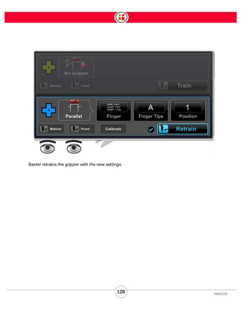
Baxter retrains the gripper with the new settings.
128Intera 3.0

Appendix C: Configuring External
Devices
Baxter communicates to external machines via its open logic ports in one integrated DB15
connector or by adding an external Ethernet-connected Modbus Remote Terminal Unit (RTU).
Attach a terminal block to the DB15 connector to accommodate two signal lines—one in and one
out—and provide lines for the e-stop and a safety mat.
TABLE 1. DB15 Pinouts
DB15 Pin1 E‐Stop E Stop Switch
9 E‐Stop E Stop Switch2 Safety Mat To +5 (6) via safety mat cable
10 Safety Mat To GND (8) for safety mat3 Safety Mat To +5 (5) for safety mat
11 Safety Mat To GND (13) via safety mat cable4 Torso 0 In Torso 0 In (Ready In)
12 Torso 0 In Return Torso 0 In Return (Ready In Return)5 1K to +5 To (3) for safety mat
13 GND To (11) via safety mat cable6 1K to +5 To (2) via safety mat cable
14 GND7 Torso 0 Out Torso 0 Out (Done Out), +5v ‐ +24v, MUST BE LIMITED TO 10ma MAX
15Torso 0 Out
ReturnTorso 0 Out Return (Done Out Return), GND
8 GND To (10) for safety mat
129Intera 3.0

Note:
• Torso 0 In is FALSE when current is flowing, and TRUE otherwise. A
disconnected input will appear as TRUE.
• Torso 0 Out is open when FALSE, and closed (current flowing) when TRUE.
Pin 4: Torso 0 In (Ready In), 5v – 24v
Pin 12: Torso 0 In Return (Ready In Return)
Pin 7: Torso 0 Out (Done Out), +5v – +24vMUST BE EXTERNALLY CURRENT LIMITED,
Pin 15: Torso 0 Out Return (Done Out Return),GND
10ma MAX
130Intera 3.0

Connecting a Modbus Remote Terminal Unit (RTU) to Baxter
1. Set the IP address of the Modbus device to:
169.254.#.#
where # is any number between and including 1 to 254, and the subnet mask is
255.255.0.0. (Please refer to the RTU manufacturer’s instructions for assigning
the IP address.)
Note: With Baxter 1.1 software, Rethink Robotics qualified the Moxa ioLogik E1212
Remote Terminal Unit.
2. With Baxter shut down and powered off, attach the device to the Ethernet port.
3. Turn on the device.
4. Power Baxter on.
5. Go to Settings > Hardware Settings > Configure I/O Device > Configure Modbus.
131Intera 3.0

6. In the device list screen, select the + icon to add a device.
7. In the configure new device screen, enter the following:
• Device Name – Keep the default, or enter a descriptive name for the device
(maximum 16 characters).
Tip: Create an easily recognizable name. This makes it easier to identify when creating
and adding signals to a task.
• Number of Lines In and Lines Out
• IP Address
To change the default Input and Output Base of 0, and parameters, select the
Advanced icon.
8. Click Done to save the new device.
132Intera 3.0
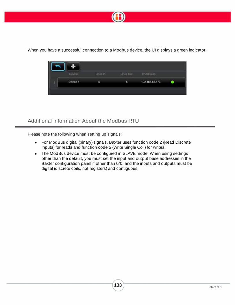
When you have a successful connection to a Modbus device, the UI displays a green indicator:
Additional Information About the Modbus RTU
Please note the following when setting up signals:
• For ModBus digital (binary) signals, Baxter uses function code 2 (Read Discrete
Inputs) for reads and function code 5 (Write Single Coil) for writes.
• The ModBus device must be configured in SLAVE mode. When using settings
other than the default, you must set the input and output base addresses in the
Baxter configuration panel if other than 0/0, and the inputs and outputs must be
digital (discrete coils, not registers) and contiguous.
133Intera 3.0

Appendix D: Transfer Tasks from
One Baxter to Another
You can copy tasks from one robot and transfer them to another using a USB memory stick. Details
of the task are included in the transfer. You only need to update the device referenced. This capabil-
ity is useful when a factory is using multiple Baxters to perform the same task.
When transferring tasks to a different robot, variability across robots and fiducials are not taken into
account.
Note: If you have multiple exports of tasks on the same USB stick, only the most recent set of
exported tasks will be imported.
How to Export Tasks from a Robot
1. Insert a USB device, formatted as FAT32, into the USB port on Baxter.
2. On Baxter, go to
3. Main Screen > Settings > Advanced > Export/Import Tasks.
4. Scroll to Export.
134Intera 3.0

5. Press OK. Baxter displays its tasks. All tasks are selected by default.
6. To select just some of the tasks, scroll to each particular task and select it or
deselect it by pressing OK when it is highlighted.
135Intera 3.0

7. When the tasks you want to export are highlighted, press the Baxter button on
the Navigator, then select Export.
A bar displays the progress of the export to the USB.
Note: If you press the Back button during the export process, the export will be cancelled.
How to Import Tasks to a Robot
1. Insert a USB device that contains exported tasks into the USB port on Baxter.
2. On the Baxter that will receive the copied tasks, go to
3. Main Screen > Settings > Advanced > Export/Import.
4. Scroll to Import.
5. Press the OK button on the Navigator.
A bar displays the progress of the import.
Note: If you press the Back button during the import process, the import will be cancelled.
COPIED TASKS
If Baxter already had a task named “Task1” in its Task Gallery, the newly created name would be
incremented by .1, e.g., “Task1.1.”
A TROUBLESHOOTING CHECKLIST FOR IMPORTED AND EXPORTED TASKS
Because the physical world of the two Baxters – the Baxter from which the task was imported and
the Baxter to which the copied task was exported – are not identical, you may need to refine these
tasks. Here is a checklist of troubleshooting situations you may encounter:
• The grippers may not match.
• Different Baxter heights – The task runs but the robot is missing picks and places
because the height of the pedestal is different (the wheels have been adjusted;
the original Baxter is mounted to a table) etc.
• The task runs but Baxter’s position from the work surface is different from the
original, in distance and/or angle.
136Intera 3.0

• The task runs but the workspace is different from the original in some way. In this
case, the operator has to tweak the layout of the workspace or the paths of
Baxter’s arms.
• The lighting is different. That could affect Baxter’s vision. See “How to Change
the Lighting Settings for Baxter’s Cameras.”
137Intera 3.0

Appendix E: Tips & Best Practices
Training Actions
• Before starting to train a Pick action with the parallel gripper, set the fingers in the
correct position for the grasp type (inside/outside).
• When training multiple Pick or Place actions in a row, it helps increase
performance accuracy to have an object in hand.
• Train locations within the workspace limits.
• To create a valid task, train both a Pick and a Place location for the arm
performing the task. Remember: a task must be made up of a pick followed by a
place.
Vertical and Non-Vertical Tasks
As of Intera 3 software, it is no longer necessary to train a non-vertical task to take advantage of
faster speeds, location-based picks, force sensing, etc. There are no performance differences
between vertical and non-vertical tasks. However, vision search is available only for vertical Picks.
The camera does not operate for non-vertical tasks.
Workspace and Robot Joint Limits
The ability of Baxter to perform actions at any given location is affected by the physical limits of the
arms. When training an action, consider:
• Each of the robot’s joints has limits. The closer you are to the edge of these
limits, the greater the chance the robot will be unable to train an action.
• If the orientation of the training cuff on demonstration is twisted near a limit, the
robot may have trouble when you run the task. If you notice Baxter cannot reach
a location, try moving the location closer to the robot, or re-train the location.
• The possible vertical range of an action is reduced as you move closer to the
edges of the maximum available workspace of the robot.
138Intera 3.0

Waypoint Wisdom: Tips for Creating Custom Paths
Note: Click here for a Baxter University video tutorial about waypoints and paths.
• The first and last point you create for an action, which becomes the approach
and retract point, is important. When creating these points, think about their rela-
tion to the picks and places, and make sure their pose makes sense. For exam-
ple, is there a clear path between the approach point and the pick? It will be a
straight line along the gripper. Keep this in mind when planning your approach
and retract points.
• As of Baxter software 2.1, it is no longer necessary -- or even desirable -- to
define a large number of waypoints when training a path. The more transit points
you add, the longer the path and therefore, the more time the task will take. Also,
if you train a number of waypoints relatively close together along a path, Baxter's
arm movement will become jerky. Therefore, the best practice is to train just
those points needed to avoid obstacles that may be in Baxter's path.
• Think Baxter’s arm path through before you create it. Do a dry run by manually
moving the arm before creating the waypoints. Move the arm through your
planned path and don’t focus just on the wrist. Instead, take into account the
entire length of the arm as you move through the path. Do the joints – including
the shoulder and elbow – ever approach their limits? Does Baxter’s arm as a
whole ever get twisted or distorted? Does the Navigator start on one side of the
arm and end up on the other? Baxter will work better when its arm remains rela-
tively untwisted as it moves along its path.
• When you reach the end of your path, it’s a good idea to make sure the wrist is
still able to rotate easily when it performs the place. Try to make sure the wrist
rotation is in the mid-range of its limits.
Grasping Objects
The ability for Baxter to successfully grasp and pick up objects depends on several factors,
including:
• Gripper selected and associated components (such as, fingers, finger tips,
vacuum cup size)
• Proper gripper configuration
• Grasp position relative to the object’s center of gravity
• Grip detection threshold setting
• Consistency of the pickup location on the work surface
139Intera 3.0

The illustration below (not to scale) shows the Finger Selection and Position Guide included in the
inside cover of the Parallel Gripper Kit. Key concepts to remember when choosing fingers and
position are:
1. Place the object in the center of the chart in the same orientation as the robot will
grasp it.
2. Use the object’s edges to determine the best fingers and position.
• Consider finger tip thickness, as it will alter grasp range.
• There should be at least 1 cm of clearance between the part and the finger
tips when the gripper is open (outside grasp).
• If object edges are on the lines of a zone, choose the next position, or next
size fingers.
3. Try different finger tips based on the shape and size of the object.
4. Consider adding a limiter to give additional stability.
Also, Consider cutting and adhering the silicon material included in the gripper kit
to the flat finger tips to provide a better grip when grasping objects with the flat
finger tips.
140Intera 3.0

You may also want to try different locations on the object for grasping. Consider which would be
better—an “outside grasp” shown in the left illustration below, or an “inside grasp” shown on the
right.
Object Training and Visual Search
• Visual search works only for vertical tasks.
• Generally, using a visual search area will take more time to complete a task.
• Keep the work surface clear of clutter.
• Choose solid-color work surfaces.
• Glare from the object or surface can affect object training.
• Aim to have high contrast between an object and the surface.
• Baxter cannot learn an object if it is moving during training.
• See “Training a Pick Using Vision” on page 34 and “Camera Settings” on page 43
for more details about how to effectively train Baxter using vision.
Conveyors
• Pick actions from conveyors require object training and a visual search area;
Baxter cannot learn a blind, moving, Pick action.
• Trace the smallest possible visual search area necessary for the robot to be able
to find the object and complete the Pick action along the conveyor.
o If the object is located in the center of the conveyor widthwise, trace a
narrower area that runs lengthwise along the conveyor.
Outside grasp Inside grasp
141Intera 3.0

o If the location of the object is randomly located anywhere on the conveyor
belt, trace an area that is the full width of the conveyor.
Stacks
• When training a stack above the waist, train the bottommost object in the stack
and use Contact or First as the Action Control. See “How to Make Detailed
Modifications to an Action (Advanced Settings Screen)” on page 68.
Multiple Locations
When training multiple Pick or Place actions in a row, always have an object in hand to increase
accuracy in performance.
142Intera 3.0

Appendix F: Safety Mats
Baxter supports the optional use of a safety mat—a 4-wire Normally Open (N.O) configured mat of
any size or shape (user-supplied, not included. To connect a safety mat to Baxter, use a terminal
block that can connect to the DB15 connector on the I/O panel on the back of the robot’s waist, and
support a male-configured DB15 connector for the e-stop button.
IMPORTANT If e-stop wiring is not properly configured, the Baxter arms will not operate.
To configure the terminal block:
1. Power Baxter down and remove the e-stop assembly.
2. Connect the terminal block connector to the DB15 connector where the e-stop
button was originally connected.
3. Run the bare wires from the safety mat into the terminal block, and wire them
with appropriate jumpers, as shown in the diagram on the following page. To
ensure full e-stop support, pass the e-stop wiring through to the illustrated pins
on the extended DB15 connector.
4. Once configured, with the terminal block and e-stop properly connected, power
Baxter on per normal operation.
Note: When Baxter is working, if a user steps on the safety mat, Baxter will slow down
and express surprise.
A wiring diagram is included on the following page.
143Intera 3.0
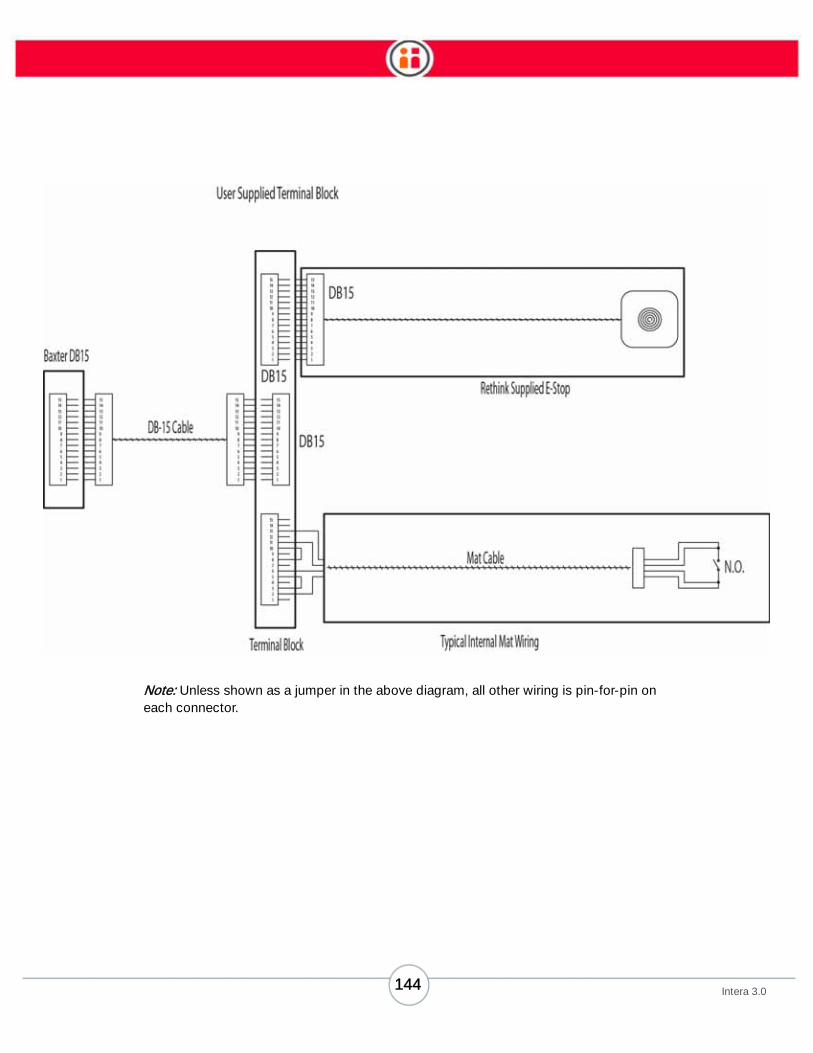
Note: Unless shown as a jumper in the above diagram, all other wiring is pin-for-pin on
each connector.
144Intera 3.0

145Intera 3.0
Appendix G: Support & Warranty
The Baxter robot comes with a one (1) year or 2,100 hours of operation (whichever occurs first)
limited warranty.
If there is a problem with your robot and you are unable to resolve it, try shutting down and
restarting the robot. If the problem persists, contact your authorized Rethink Robotics service
provider for technical support. You will need to provide the model and serial number of the robot
experiencing the problem. These can be found on the back of the robot near the power button.
If the product is no longer within the warranty period, the authorized Rethink Robotics service
provider will provide an estimate of the technical support or repair costs.


Last updated August 1, 2014 P/N 26004 – Rev C