user guide oi/genie–en genie ii – sizing & selection ... · *abb genie software has been...
TRANSCRIPT

User guide OI/Genie–EN
Genie II – Sizing & Selection Software Wedge and Integral Orifice Flow Meters

The CompanyWe are an established world force in the design and manufacture of instrumentation for industrial process control, flow measurement, gas and liquid analysis and environmental applications.
As a part of ABB, a world leader in process automation technology, we offer customers application expertise, service and support worldwide.
We are committed to teamwork, high quality manufacturing, advanced technology and unrivalled service and support.
The quality, accuracy and performance of the Company’s products result from over 100 years experience, combined with a continuous program of innovative design and development to incorporate the latest technology.
L
Electrical Safety
EN ISO 9001:2000
Cert. No. Q 05907
EN 29001 (ISO 9001)
enno, Italy – Cert. No. 9/90A
Stonehouse, U.K.
This equipment complies with the requirements of CEI/IEC 61010-1:2001-2 'Safety Requirements for Electrical Equipment for Measurement, Control and Laboratory Use'. If the equipment is used in a manner NOT specified by the Company, the protection provided by the equipment may be impaired.
SymbolsOne or more of the following symbols may appear on the equipment labelling:
Warning – Refer to the manual for instructions
Direct current supply only
Caution – Risk of electric shock Alternating current supply only
Protective earth (ground) terminal Both direct and alternating current supply
Earth (ground) terminalThe equipment is protected through double insulation
Information in this manual is intended only to assist our customers in the efficient operation of our equipment. Use of this manual for any other purpose is specifically prohibited and its contents are not to be reproduced in full or part without prior approval of the Technical Publications Department.
Health and Safety
To ensure that our products are safe and without risk to health, the following points must be noted:
1. The relevant sections of these instructions must be read carefully before proceeding.
2. Warning labels on containers and packages must be observed.
3. Installation, operation, maintenance and servicing must only be carried out by suitably trained personnel and in accordance with the information given.
4. Normal safety precautions must be taken to avoid the possibility of an accident occurring when operating in conditions of high pressure and/or temperature.
5. Chemicals must be stored away from heat, protected from temperature extremes and powders kept dry. Normal safe handling procedures must be used.
6. When disposing of chemicals ensure that no two chemicals are mixed.
Safety advice concerning the use of the equipment described in this manual or any relevant hazard data sheets (where applicable) may be obtained from the Company address on the back cover, together with servicing and spares information.

Genie II – Sizing & Selection Software Wedge and Integral Orifice Flow Meters Contents
OI/Genie–EN 1
Contents
1 Installation ........................................................................................................................................ 21.1 Setup ...................................................................................................................................... 2
2 Introduction ...................................................................................................................................... 32.1 Features .................................................................................................................................. 32.2 Data Inputs & Units Screen ...................................................................................................... 62.3 Sizing Integral Orifice meters (1330L, FPD510 IOMaster) ....................................................... 142.4 Error Messages ..................................................................................................................... 17
Appendix A Fluid Properties Screen .................................................................................................. 18

Genie II – Sizing & Selection Software Wedge and Integral Orifice Flow Meters 1 Installation
1 InstallationIt is always best to close any open Window applications or virus utilities before installing any WindowsProgram application. Additionally, system privileges must be provided for loading components intoc:/windows/system directories.
Any previous version of the ABB GENIE II Program should be removed. This is done in the WindowsControl Panel, Add/Remove Programs.
1. Download the ABB GENIE II Program.
2. In the Windows Start Button on the Microsoft Task Bar, go to Settings>Control Panel>, thendouble-click on Add/Remove Programs and follow the on screen instructions for “Add NewPrograms”. (For versions downloaded to your PC, go to the directory into which the Program wasdownloaded).
3. Click on the button for “Add a Program from Floppy Disk or CD-ROM ’ and follow the on-screeninstructions
The Setup Program should start by ‘Copying initialization files.’ If you are a first time user, the Setup mayrequest to shutdown and restart your computer. This is a standard Microsoft setup and allows for properregistration. Click OK and allow the system to reboot. Any error during the install process should bereported to your IS administrator.
The Setup Program will check for sufficient disk space. If there is insufficient space, Setup will stop theinstallation process and advise you to clear space before proceeding.
1.1 SetupTo start the ABB GENIE II Program, click the Start button on the Microsoft Task Bar, then Programs>ABBProgram Suite.
To have easy access to the ABB GENIE II Program, create a desktop icon. Once the desktop icon iscreated, all you need to do is double-click the icon.
System Requirements
Computer: Pentium or better
Memory: 12 MB RAM
Minimum Disk Space: 25 MB
Operating System: MS Windows *
Networking: Capabilities Available
Other Software: MS Office
Display resolution 800 x 600 pixels
Display color 256 color required, 32 bit preferred
*ABB Genie software has been demonstrated to execute successfully on Windows 7 operating systemshowever certain system configurations, firewall setups or other IT limiting applications may cause theprogram to crash, freeze or not run at all. If this is encountered is it recommended to run the software in theWindows XP mode.
2 OI/Genie–EN

Genie II – Sizing & Selection Software Wedge and Integral Orifice Flow Meters 2 Introduction
2 IntroductionThis software is an essential tool to assist in the selection and application of ABB flow meters and tosupport troubleshooting issues. Many features have been incorporated to provide access to standardphysical properties, generic and intricate process engineering conversions and “what if” decision makingwith point and click simplicity.
Design specification changes are easily entered and instantly calculated. Entries that do not meet specificmeter design criteria are color-coded, with results blocked in yellow - indicating caution – or blocked in red– indicating that a specification has been violated.
Advanced users may take advantage of entering specific data relating to tap elevation, pipe roughness andprocess variables to further define the sizing criteria.
Project information and other comments may be entered directly from the main sizing screen for futureretrieval and printing.
The Results show meter calculations, design details, pressure drop factors, power consumption and flowelement hourly and yearly operating costs, and more. References for the calculation basis can be extractedfrom the physical property and other standard data tables.
Results can be saved directly to Word and Excel formats, and e-mailed to end users, purchasing contacts,or co-workers.
2.1 FeaturesText Toolbar: File, Edit, View, Start, Results, Window, Help
Icon Toolbar: Open, Save, Print, Print Preview, Cut, Copy, Paste, Start, Pause, Stop, Word Results, ExcelResults, Quick View, Graph Results, and Windows Toolbar.
The Toolbar for the Initial Default Screen includes the following buttons:
Data Inputs & Units Enter all required data and appropriate units.
Fluid Properties Sets all fluid properties based on selected fluid.
Standard Conditions Enter both standard and flowing conditions.
Comments & Info Enter any information and comments to be saved.
Calculated Results Calculate all results and displays in text format.
Graphical Results Calculate all results and displays graphically.
Calculate Calculate all sizing results.
Note. This program is intended to be used as a tool for the selection and sizing of ABB flow meters based on application conditions. All results are estimates using either empirical data or industry accepted equations and may not reflect exact results when in actual use. ABB Automation Inc. provides this program “as is” with no warranty of any kind. The user assumes full responsibility for its application and use of data and results.
OI/Genie–EN 3
Genie II – Sizing & Selection Software Wedge and Integral Orifice Flow Meters 2 Introduction
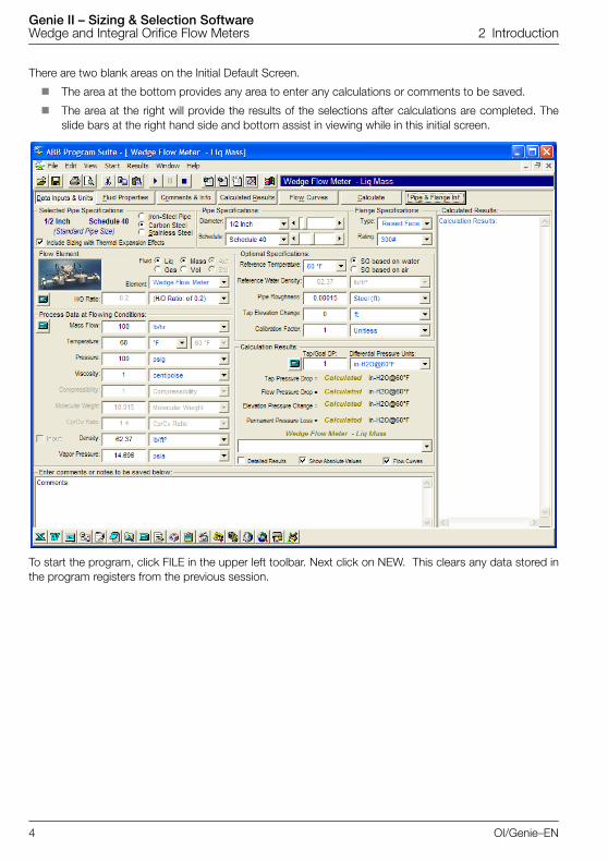
There are two blank areas on the Initial Default Screen.
The area at the bottom provides any area to enter any calculations or comments to be saved.
The area at the right will provide the results of the selections after calculations are completed. Theslide bars at the right hand side and bottom assist in viewing while in this initial screen.
To start the program, click FILE in the upper left toolbar. Next click on NEW. This clears any data stored inthe program registers from the previous session.
4 OI/Genie–EN
Genie II – Sizing & Selection Software Wedge and Integral Orifice Flow Meters 2 Introduction
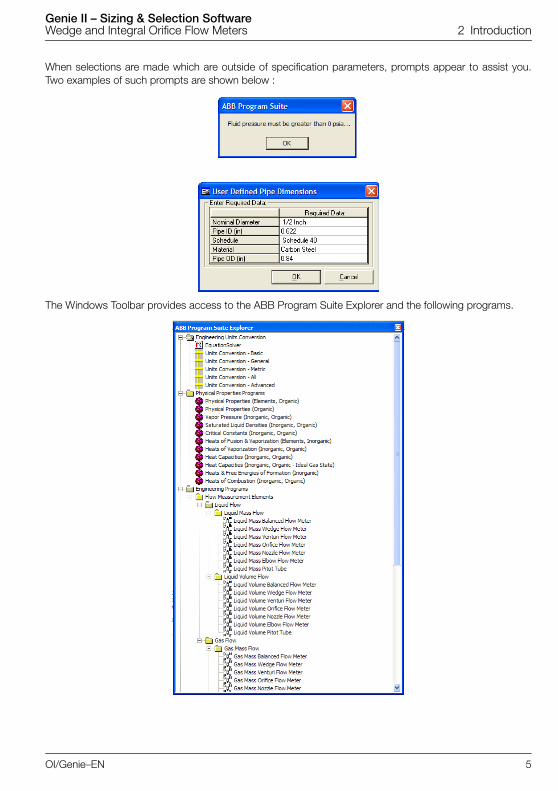
When selections are made which are outside of specification parameters, prompts appear to assist you.Two examples of such prompts are shown below :
The Windows Toolbar provides access to the ABB Program Suite Explorer and the following programs.
OI/Genie–EN 5

Genie II – Sizing & Selection Software Wedge and Integral Orifice Flow Meters 2 Introduction
2.2 Data Inputs & Units ScreenThe Data Inputs & Units screen is the default opening screen and sizing calculations may be performed withno further window selections, providing the process data is in actual conditions. Described below are thevarious sections of the opening screen.
Selected Pipe Specifications
Select Nominal Diameter between ½ inch and 36 inch by utilizing the drop down menu, or the slidebar to the right of the drop down menu.
Select Pipe Schedule by utilizing the drop down menu or the slide bar.
Select the material from Iron-Steel, Carbon or Stainless Steel.
Flow Element
Fluid – select the fluid phase (Liquid or Gas) and flow type (Mass or Volume units).
Element – Select the type of element to be sized, using the drop down box. This selection changes thedescription and content of the meter characteristic selection below.
The meter types available (and the corresponding characteristic) are:
Wedge Flow Meter (H/D ratio or input Kd2)
Venturi Flow Meter (Beta ratio or input bore diameter)
Orifice Flow Meter (Beta ratio or input bore diameter)
Nozzle Flow Meter (Beta ratio or input bore diameter)
Elbow Flow Meter (Radius of curvature)
Pitot Tube. (Velocity Head factor)
Example: If the selection is changed from a Wedge to a Nozzle, the box below changes from a H/D Ratioselection to a Radius of Curvature data entry. Select and highlight the default number of 1 and enter thecorrect radius value. In the drop down box to the right, select the unit of measurement appropriate to theradius value.
Note. Once selected, the chosen Pipe Specifications are highlighted at the left. If the text in this area is blue, the pipe sizing exists. If the text is red, it is a non-standard pipe size. For Wedge products, not all pipe sizes/schedules may be offered within the standard product line and may require a factory quotation.
Note. Changes made in this section are reflected in the area below - “Process Data at Flowing Conditions”.
Note.
1. The Pitot Tube option is historical and does not allow correct sizing of either a Torbar or a PitoMaster.
2. The sizing of Venturi Tubes, Nozzles, etc is for guidance only and should only be used to establish that a particular DP value is viable for the entered flow data, not for establishing meter geometry or for calculating an accurate meter bore.
Note. based on the selection of, for example, Liquid or Gas, certain selections will be disabled and cannot be changed, selected or highlighted.
6 OI/Genie–EN

Genie II – Sizing & Selection Software Wedge and Integral Orifice Flow Meters 2 Introduction
Process Data input
Process data may be entered in one of the following ways:
Actual Conditions
1. Process data for actual conditions may be entered directly on the opening default input screen.Items highlighted in blue are the required inputs.
2. If required, select the Fluid Properties button, enter pressure, temperature and density, then selectone of the fluid properties sections at the bottom of the window bottom and find the fluid beingmeasured. Calculations for MW, vapor pressure etc are calculated and brought forward to thecalculation screen.
The Process Data at Flowing Conditions can be selected, highlighted and new inputs entered. Drop downboxes contain additional options.
Parameters in the area “Process Data at Flowing conditions” :
Volumetric Flow Rate
Temperature
Pressure
Viscosity
Compressibility
Molecular Weight
Cp/Cv Ratio
Density
Vapor Pressure
Parameters in the area “Optional Specifications” are as follows. If the conditions can be selected andhighlighted, new inputs can be entered. Drop down boxes contain additional options.
Reference Temperature (used for SG calculation)
Reference Density
Pipe Roughness
Tap Elevation Change – used when considering a vertical installation
Calibration Factor – changing the calibration factor (to any value other than 1) changes the defaultmeter factor. Such changes should only be made by factory personnel.
Parameters in the area Calculation Results are as follows:
Select Differential Pressure Units – the default is “in-H20 @60F”All the following parameters will then be calculated in the selected units
Tap Pressure Drop
Flow Pressure Drop
Elevation Pressure Drop
Permanent Pressure Loss
Note. If selection areas are disabled, they are not required for the current selection.
Note. If selection areas are disabled, they are not required for the current selection.
OI/Genie–EN 7
Genie II – Sizing & Selection Software Wedge and Integral Orifice Flow Meters 2 Introduction
Below these results, a drop box is available to select a program variable or constant and monitor the valuebased on program input or changes.
Calculated Results – this area to the right defaults to a short form version of the results of the calculation,updated as appropriate whenever the Start button (an icon on the menu bar) or the Calculate button areclicked. This displays the minimum level of data results for sizing. A long form report can be generated byclicking the box next to Detailed Results and clicking once more on Start or Calculate . This option can bedeselected by clicking again.
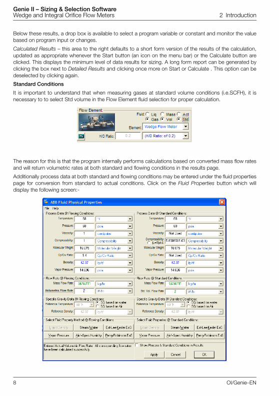
Standard Conditions
It is important to understand that when measuring gases at standard volume conditions (i.e.SCFH), it isnecessary to to select Std volume in the Flow Element fluid selection for proper calculation.
The reason for this is that the program internally performs calculations based on converted mass flow ratesand will return volumetric rates at both standard and flowing conditions in the results page.
Additionally process data at both standard and flowing conditions may be entered under the fluid propertiespage for conversion from standard to actual conditions. Click on the Fluid Properties button which willdisplay the following screen:-
8 OI/Genie–EN
Genie II – Sizing & Selection Software Wedge and Integral Orifice Flow Meters 2 Introduction
Follow steps similar to those described above for actual conditions, but initially enter data for the fluid atboth standard (eg STP, NTP, etc) and flowing (Actual) conditions. The pressure, temperature and density atstandard conditions should be entered on the right half of the screen. Enter the flowing (Actual) pressure,temperature and density on the left side of the screen.
Data may be imported from the Fluid Properties buttons as before, but on this occasion for both standardand flowing conditions. Enter the flow rate at standard conditions and click Apply. The program willcalculate mass and actual volumetric rate under the flowing conditions. As before clicking on Apply and OKwill import the data to the main screen for final calculations.
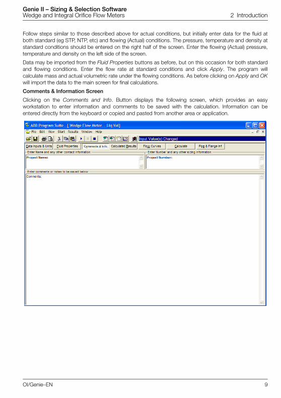
Comments & Information Screen
Clicking on the Comments and Info. Button displays the following screen, which provides an easyworkstation to enter information and comments to be saved with the calculation. Information can beentered directly from the keyboard or copied and pasted from another area or application.
OI/Genie–EN 9

Genie II – Sizing & Selection Software Wedge and Integral Orifice Flow Meters 2 Introduction
Calculated Results
Clicking on the Calculated Results button displays this screen which provides all the calculated results,displaying them in text format.
10 OI/Genie–EN
Genie II – Sizing & Selection Software Wedge and Integral Orifice Flow Meters 2 Introduction
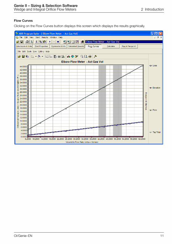
Flow Curves
Clicking on the Flow Curves button displays this screen which displays the results graphically.
OI/Genie–EN 11

Genie II – Sizing & Selection Software Wedge and Integral Orifice Flow Meters 2 Introduction
Results
The ABB GENIE II program can display results within certain Microsoft products, including Word & Excel.From the menu bar select Results, followed by the format required.
12 OI/Genie–EN

Genie II – Sizing & Selection Software Wedge and Integral Orifice Flow Meters 2 Introduction
The Microsoft application will then open and be populated with the results. Samples of the text andgraphical sheets for Word are shown below. These can be generated into a final report, logged for futurereference, or e-mailed to project personnel. Results may be generated in a short or long form.
OI/Genie–EN 13

Genie II – Sizing & Selection Software Wedge and Integral Orifice Flow Meters 2 Introduction
2.3 Sizing Integral Orifice meters (1330L, FPD510 IOMaster)The following procedure describes the best way to select the most appropriate plate for an integral orificemeter such as the 130L or FPD510 IOMaster, and calculate the resultant DP generated.
1. Start the Genie program. The following screen will then display.
2. In the Element pulldown, select Orifice Flow Meter.
3. In the Flow Element section, use the Fluid radio buttons to select either Liquid or Gas and to selecteither Mass or Volume units.
4. Select the Pipe Diameter (½, 1 or 1.5 in.) and Schedule (40S or 80S). Ignore the Flange Type andRating.
14 OI/Genie–EN
Genie II – Sizing & Selection Software Wedge and Integral Orifice Flow Meters 2 Introduction
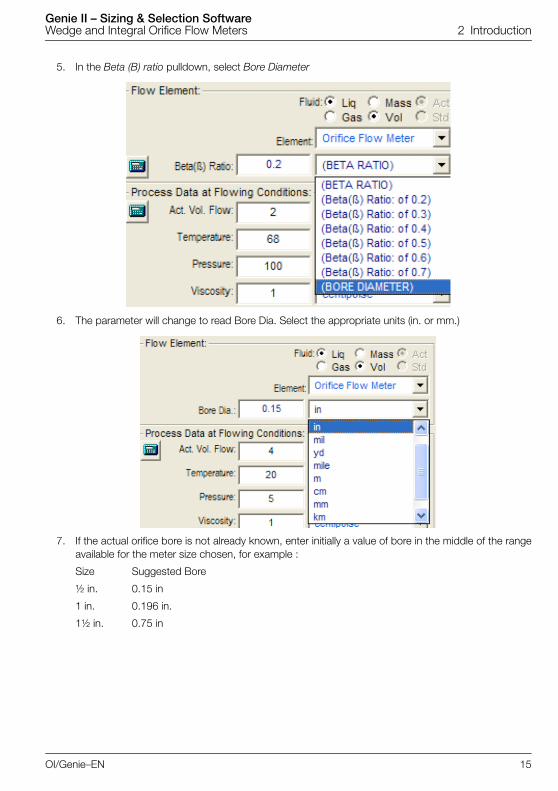
5. In the Beta (B) ratio pulldown, select Bore Diameter
6. The parameter will change to read Bore Dia. Select the appropriate units (in. or mm.)
7. If the actual orifice bore is not already known, enter initially a value of bore in the middle of the rangeavailable for the meter size chosen, for example :
Size Suggested Bore
½ in. 0.15 in
1 in. 0.196 in.
1½ in. 0.75 in
OI/Genie–EN 15

Genie II – Sizing & Selection Software Wedge and Integral Orifice Flow Meters 2 Introduction
8. Enter the process data, selecting the appropriate units for each parameter.
9. Press the Calculate button. Read off the calculated DP. If the units need to be amended, select the appropriate units and press the Calculate button again torecalculate the DP in the new units
10. In this example the DP and overall pressure loss values are quite high.To reduce the DP, select the next higher bore size and enter the new value into the Orifice Bore box.To increase the DP, select the next lower bore size and enter the new value into the Orifice Bore box.
11. Hit Calculate button and read off the new DP and pressure loss.
Repeat steps 10 and 11 until an acceptable DP is found.
Record the values of the chosen orifice bore and the resultant DP value. They will be needed when theproduct is coded in ConfigurX to select the appropriate orifice bore and Transmitter element (DP Span ).
For the latter, for optimum accuracy always choose the element with the lowest DP span that willaccommodate the calculated DP.
16 OI/Genie–EN

Genie II – Sizing & Selection Software Wedge and Integral Orifice Flow Meters 2 Introduction
2.4 Error MessagesDepending on the process condition entered the program may indicate errors associated withnon-standard pipe size, high pressure drop, high velocities, cavitation or other potential problems.
If this occurs it may be necessary to revise the process data or change the pipe size.
OI/Genie–EN 17

Genie II – Sizing & Selection Software Wedge and Integral Orifice Flow Meters Appendix A Fluid Properties Screen
Appendix A Fluid Properties ScreenThe Fluid Properties Screen sets all fluid properties based on the fluid selected. Options available areProcess Data @ Flowing Conditions, Flow Rate @ Flowing conditions and Specific Gravity @ FlowingConditions. If you have opted to enter or change information, click on Apply once all changes are complete.
Fluid Properties @ Flowing Conditions
This provides 4 options. Click on the relevant button.
1. Liquid Density
Simply select the fluid, enter the correct temperature and click OK to continue.
18 OI/Genie–EN

Genie II – Sizing & Selection Software Wedge and Integral Orifice Flow Meters Appendix A Fluid Properties Screen
2. Vapor Pressure
Simply select the fluid, enter the correct temperature and click OK to continue.
3. Steam/Water Density
OI/Genie–EN 19

Genie II – Sizing & Selection Software Wedge and Integral Orifice Flow Meters Appendix A Fluid Properties Screen
4. Peng-Robinson (Fluid Property Evaluation)
Peng Robinson allows the user to enter a gas mixture and will then calculate density and otherparameters for the pressure and temperature entered on the main sizing screen.
a Ensure that the working pressure and temperature for the gas mixture (whether standard orflowing conditions) has been entered on the previous screen.
b To set up a gas mixture, click on the 1st component required with the left mouse key. Forsubsequent components hold down the CTRL key and click on required components with leftmouse key.
c Once components are selected, click on the enter button to confirm entry, the next screen willappear.
d Click on each compound in turn and enter the fraction of the mix for that component. Thefraction is entered in a format such that 90%=0.9; 50% = 0.5; 10% = 0.1 etc. Thecomposition sum must equal 1 or an error message will appear.
20 OI/Genie–EN
Genie II – Sizing & Selection Software Wedge and Integral Orifice Flow Meters Appendix A Fluid Properties Screen
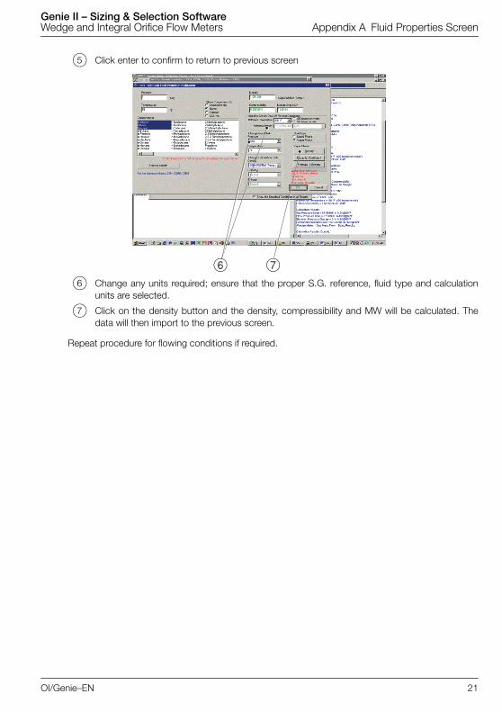
e Click enter to confirm to return to previous screen
f Change any units required; ensure that the proper S.G. reference, fluid type and calculationunits are selected.
g Click on the density button and the density, compressibility and MW will be calculated. Thedata will then import to the previous screen.
Repeat procedure for flowing conditions if required.
6 7
OI/Genie–EN 21

Genie II – Sizing & Selection Software Wedge and Integral Orifice Flow Meters Notes
Notes
22 OI/Genie–EN

Genie II – Sizing & Selection Software Wedge and Integral Orifice Flow Meters Notes
OI/Genie–EN 23

Genie II – Sizing & Selection Software Wedge and Integral Orifice Flow Meters Notes
24 OI/Genie–EN

Products and customer support
Automation SystemsFor the following industries:— Chemical & Pharmaceutical— Food & Beverage— Manufacturing— Metals and Minerals— Oil, Gas & Petrochemical— Pulp and Paper
Drives and Motors— AC and 6 Drives, AC and DC Machines, AC Motors to
1kV— Drive Systems— Force Measurement— Servo Drives
Controllers & Recorders— Single and Multi-loop Controllers— Circular Chart and Strip Chart Recorders— Paperless Recorders— Process Indicators
Flexible Automation— Industrial Robots and Robot Systems
Flow Measurement— Electromagnetic Flowmeters— Mass Flowmeters— Turbine Flowmeters— Wedge Flow Elements
Marine Systems & Turbochargers— Electrical Systems— Marine Equipment— Offshore Retrofit and Refurbishment
Process Analytics— Process Gas Analysis— Systems Integration
Transmitters— Pressure— Temperature— Level— Interface Modules
Valves, Actuators and Positioners— Control Valves— Actuators— Positioners
Water, Gas & Industrial Analytics Instrumentation— pH, Conductivity and Dissolved Oxygen Transmitters
and Sensors— Ammonia, Nitrate, Phosphate, Silica, Sodium,
Chloride, Fluoride, Dissolved Oxygen and Hydrazine Analyzers
— Zirconia Oxygen Analyzers, Katharometers, Hydrogen Purity and Purge-gas Monitors, Thermal Conductivity
Customer supportWe provide a comprehensive after sales service via a Worldwide Service Organization. Contact one of the following offices for details on your nearest Service and Repair Centre.
UKABB LimitedTel: +44 (0)1453 826661Fax: +44 (0)1453 829671
USAABB Inc.Tel: +1 215 674 6000Fax: +1 215 674 7183
Client WarrantyPrior to installation, the equipment referred to in this manual must be stored in a clean, dry environment, in accordance with the Company's published specification.Periodic checks must be made on the equipment's condition. In the event of a failure under warranty, the following documentation must be provided as substantiation:— A listing evidencing process operation and alarm
logs at time of failure.— Copies of all storage, installation, operating and
maintenance records relating to the alleged faulty unit.

Contact us
OI/G
enie
–EN
09.2
011
ABB LimitedProcess AutomationOldends LaneStonehouseGloucestershire GL10 3TAUKTel: +44 1453 826 661Fax: +44 1453 829 671
ABB Inc.Process Automation125 E. County Line RoadWarminsterPA 18974USATel: +1 215 674 6000Fax: +1 215 674 7183
www.abb.com
NoteWe reserve the right to make technical changes or modify the contents of this document without prior notice. With regard to purchase orders, the agreed particulars shall prevail. ABB does not accept any responsibility whatsoever for potential errors or possible lack of information in this document.
We reserve all rights in this document and in the subject matter and illustrations contained therein. Any reproduction, disclosure to third parties or utilization of its contents in whole or in parts – is forbidden without prior written consent of ABB.
Copyright© 2011 ABBAll rights reserved