user guide - coldesi
TRANSCRIPT

COMPRESS IUV600S SERIES PRINTER
ALL INFORMATION CONTAINED IN THIS DOCUMENT IS PROVIDED AS IS WITHOUT WARRANTY OF ANY KIND.
THE CREATOR OF THIS DOCUMENT , HEREINAFTER REFERRED TO AS THE 'WRITER' HEREBY DISCLAIMS ALL
WARRANTIES, EXPRESSED, IMPLIED OR OTHERWISE, INCLUDING WARRANTIES OF MERCHANTABILITY,
FITNESS FOR A PARTICULAR PURPOSE, AND NON-INFRINGEMENT OF INTELLECTUAL PROPERTY RIGHTS. THE
WRITER DOES NOT ASSUME OR AUTHORIZE ANY OTHER PERSON TO ASSUME FOR IT ANY OTHER LIABILITY IN
CONNECTION WITH THIS CONTENT. IN NO EVENT SHALL THE WRITER BE LIABLE TO THE READER OF THE
CONTENT OF THIS DOCUMENT, OR ANY SUBSEQUENT USER, INCLUDING THE ULTIMATE END-USER, IN
CONTRACT, TORT, WARRANTY, STRICT LIABILITY, OR OTHERWISE FOR ANY SPECIAL, INDIRECT, INCIDENTAL
OR CONSEQUENTIAL DAMAGES, INCLUDING BUT NOT LIMITED TO, THE COST OF LABOR, REQUALIFICATION,
DELAY, LOSS OF PROFITS OR GOODWILL, EVEN IF THE WRITER IS ADVISED OF THE POSSIBILITY OF SUCH
DAMAGES. BY LOOKING AT THE CONTENT OF THIS DOCUMENT THE READER AGREES THAT THEY HAVE READ
AND AGREE TO THE ABOVE CONDITIONS ENTIRELY.
USER GUIDE
REV. 1.00 COMPRESS-IUV600S--1.00
06/05/2015

Compress iUV600s Series User Guide
2
This page has been intentionally left blank

Compress iUV600s Series User Guide
i
Important Notice
For Users in Europe
IMPORTANT:
This is a Class A product approved for industrial environments. In some
environments this product may cause radio interference in which case you may
be required to take measures to re-locate this product.
For Users in the United States
This equipment has been tested and found to comply with the limits for a Class A digital device,
pursuant to Part 15 of the FCC Rules. These limits are designed to provide reasonable protection
against harmful interference when the equipment is operated in a commercial environment.
This equipment generates, uses, and can radiate radio frequency energy and, if not installed and
used in accordance with the instruction manual, may cause harmful interference to radio
communications. Operation of this equipment in a residential area is likely to cause harmful
interference in which case the user will be required to correct the interference at his own expense.
Trademarks Mentioned in this Manual • COMPRESS, iUV600s, WIMS, AOD, ACCULOK AND BMS are registered trademarks or product
names of IMPRESSION TECHNOLOGY. • Centronics and BiCentronics are registered trademarks or product names of Centronics Data
Computer Corporation. • Windows XP, Windows Vista, Windows 7 or greater and MS- DOS are registered trademarks or
product names of Microsoft Corporation. • Intel and Pentium are trademarks or registered trademarks of Intel Corporation. • Other company and product names may be registered trademarks or product names.
•
No part of this product or publication may be stored, reproduced, copied, or transmitted in any form or
by any means without the express permission of IMPRESSION TECHNOLOGY.
The product and the contents of this publication may be changed at any time without prior notification.
IMPRESSION TECHNOLOGY has made the best efforts to keep this publication free from error, but if you
find any uncertainties or misprints, please call us or the dealer from where you bought this equipment.
IMPRESSION TECHNOLOGY shall not be liable for any damages or troubles resulting from the use or mis-
use of this equipment or this manual either directly or indirectly.

Compress iUV600s Series User Guide
ii
Warranty Limitations
IMPRESSION TECHNOLOGY warrants part repair or replacement as a sole measure only if a failure
is found in the system or in the materials and workmanship of the product the seller produced.
However, if the cause of failure is uncertain or cannot be conclusively proved to be directly related
to defect in workmanship any part repair or replacement shall be solely at the discretion of
Impression Technology.
The warranty shall not apply to any direct or indirect loss, or compensation for the loss due to the
product that has been subject to misuse, neglect, or improper alternation whether directly or
indirectly.
ALL INFORMATION CONTAINED IN THIS DOCUMENT IS PROVIDED AS IS WITHOUT WARRANTY OF
ANY KIND. THE CREATOR OF THIS DOCUMENT , HEREINAFTER REFERRED TO AS THE 'WRITER'
HEREBY DISCLAIMS ALL WARRANTIES, EXPRESSED, IMPLIED OR OTHERWISE, INCLUDING
WARRANTIES OF MERCHANTABILITY, FITNESS FOR A PARTICULAR PURPOSE, AND NON-
INFRINGEMENT OF INTELLECTUAL PROPERTY RIGHTS. THE WRITER DOES NOT ASSUME OR
AUTHORIZE ANY OTHER PERSON TO ASSUME FOR IT ANY OTHER LIABILITY IN CONNECTION
WITH THIS DOCUMENT CONTENT. IN NO EVENT SHALL THE WRITER BE LIABLE TO THE READER
OF THE CONTENT OF THIS DOCUMENT, OR ANY SUBSEQUENT USER, INCLUDING THE ULTIMATE
END-USER, IN CONTRACT, TORT, WARRANTY, STRICT LIABILITY, OR OTHERWISE FOR ANY
SPECIAL, INDIRECT, INCIDENTAL OR CONSEQUENTIAL DAMAGES, INCLUDING BUT NOT LIMITED
TO, THE COST OF LABOR, REQUALIFICATION, DELAY, LOSS OF PROFITS OR GOODWILL, EVEN IF
THE WRITER IS ADVISED OF THE POSSIBILITY OF SUCH DAMAGES. BY LOOKING AT THE CONTENT
OF THIS DOCUMENT THE READER AGREES THAT THEY HAVE READ AND AGREE TO THE ABOVE
CONDITIONS ENTIRELY.

Compress iUV600s Series User Guide
iii
About this Manual
A. Purpose and Target Readers
This manual explains the preparations and procedures for operating the Compress iUV600s series
printer.
This is a common User Guide for the Compress series of printers. Unless specifically mentioned to
the contrary, the descriptions in this manual are common for all Compress series models.
This manual is designed to assist the end user in the use, maintenance and general troubleshooting
of the Compress series printers. Before using the Compress series printer you are required to read
and fully understand the contents and directions in this manual.
B. Manual Configuration
Section Contents
1 Safety Instructions Explains types of warnings, cautions and warnings labeled on the
printer
for both the operators of the printer and maintenance personnel. 2 Product Overview Explains the features, part names, and functions of the printer.
3 Initial Setup and Basic
Operations Explains the procedures for the initial setup & basic operations
of the printer.
4 Printing on substrates Explains the procedures of preparation for & printing to
substrates with the printer.
5 Maintenance Explains daily and other periodical maintenance of the printer.
9 Troubleshooting Explains troubles that may occur when using the printer and
how to solve them.
10 Appendix Printer specifications

Compress iUV600s Series User Guide
iv
C. Document Change History
This version of the document replaces and obsoletes all previous versions. The following table
describes the most recent changes:
Revision Date Summary of Changes
15th October 2015 Initial release

Compress iUV600s Series User Guide
v
D. Manual Notation
The following symbols are used in this manual for easier understanding of the information.
Symbol
Meaning
Meaning
Must be followed carefully to avoid death or serious bodily
injury or catastrophic damage to your equipment.
Must be observed to avoid slight or moderate bodily injury or
damage to your equipment.
Contains important information and useful tips on the operation
of the product
Indicates useful tips for operating or understanding the
equipment or getting the best performance from your
equipment.
Indicates reference pages in this manual
WARNING
CAUTION
NOTE
TIP


Compress iUV600s Series User Guide
1
GENERAL TABLE OF CONTENTS
1. Safety Instructions .................................... 7
1.1 Introduction .......................................................................... 7
1.2 Warnings, Cautions and Notes .............................................. 7
1.3 Important Safety Instructions ............................................... 8
1.4 Warning Label types and meanings .................................... 11
1.4.1 Handling the Warning Labels .............................................. 11
1.4.2 Locations of Warning Labels ............................................... 12
2. Product Overview ................................... 13
2.1 Introduction ........................... Error! Bookmark not defined.
2.2 Features .............................................................................. 13
2.2.1 High Resolution Image Quality ........................................... 13
2.2.2 Ink Supply System .............................................................. 13
2.2.3 Operation Efficiency Improvement ..................................... 13
2.2.4 Operability Improvement ................................................... 13
2.3 Part Names and Functions .................................................. 14
2.3.1 Front Section ..................................................................... 15
2.3.2 Rear Section ....................................................................... 17
2.3.3 WIMS ................................................................................. 18
2.3.4 Operation Panel ................................................................. 20
2.4 Printer Status ...................................................................... 23
2.4.1 Normal .............................................................................. 23

Compress iUV600s Series User Guide
2
2.4.2 Setup Menu ....................................................................... 23
2.4.3 Changing Printer status ...................................................... 23
3. Initial Setup & Basic Operations .............. 24
3.1 Introduction ........................................................................ 25
3.2 Before you Get Started ....................................................... 25
3.2.1 Commit to Maintenance .................................................... 25
3.2.2 Get to Know your iUV600s ................................................. 25
3.3 Choosing a Place for the Printer .......................................... 28
3.3.1 Installation Environment Requirements ............................. 28
3.3.2 Required Space .................................................................. 29
3.4 Minimum Computer Requirements .................................... 31
3.5 Basic Operations ................................................................. 32
3.5.1 Switching the Printer ON .................................................... 32
3.5.2 Switching the Printer OFF. .................................................. 34
3.5.3 Connecting the Printer to the PC ........................................ 35
3.5.4 Confirming Default Settings ............................................... 37
3.5.5 Performing a Head Clean from the Operation Panel ........... 42
3.6 Initial Setup ......................................................................... 44
3.6.1 Removal of Shipping Tape .................................................. 44
3.6.2 Remove Carriage Lock Bracket ........................................... 45
3.6.3 Initial Ink Fill Process - Colours ........................................... 46
3.6.4 Initial Ink Fill Process – White ............................................. 50
3.6.5 Loading Media for Printing ................................................. 52
3.6.6 Checking media height ....................................................... 53
3.6.7 Performing a Nozzle Check Test Print ................................. 55
3.6.8 Examining a Nozzle Check Test Print .................................. 57

Compress iUV600s Series User Guide
3
3.6.9 Bi-Directional (Bi-D) Adjustment ........................................ 58
3.6.10 Installing & Using Printer Drivers........................................ 68
4. Printing to Substrates ............................. 85
4.1 Introduction ........................................................................ 86
4.2 Prepare Your Image ............................................................. 86
4.3 Substrate Preparation ......................................................... 89
4.4 Load substrate/template to the printer .............................. 90
4.4.1 Put the template onto the Platen ....................................... 90
4.4.2 Adjust Printing Bed Height / Move Platen to the Top of Page
position 91
4.5 Print Your Image .................................................................. 91
4.6 Post-Printing ........................................................................ 92
4.7 Cancelling a Print Job .......................................................... 93
4.7.1 Introduction ....................................................................... 93
4.7.2 Cancelling the Print Job ...................................................... 93
4.7.3 Re-starting the Printer after Cancelling a Print Job ............. 93
5. General Care & Maintenance .................. 94
5.1 Introduction ........................................................................ 95
5.2 Execute a Print Head Clean at the end of production ......... 95
5.3 Run the Nozzle Check test print each day before starting
production ................................................................................... 95
5.4 Maintaining the Ink System ................................................. 95
5.4.1 Accessing the Capping Station ............................................ 95

Compress iUV600s Series User Guide
4
5.4.2 Cleaning the Flushing Tray ................................................. 97
5.4.3 Cleaning the Wiper and Head Cap ...................................... 98
5.4.4 Manual Print Head Guards Clean ........................................ 99
5.4.5 Parking the Print Head ..................................................... 100
5.4.6 Emptying the waste ink container ....................................... 101
5.5 Other Maintenance Items ................................................. 102
5.5.1 Powerful Head Cleaning ................................................... 102
5.5.2 Ink Charge ....................................................................... 104
5.5.3 Clean the CR Encoder Strip ............................................... 110
5.5.4 Clean the CR Guide (X Rail) ............................................... 113
5.5.5 Clean the CR Drive Belt, Roller and Pulley ........................ 114
5.6 General Care ..................................................................... 114
5.6.1 Environment .................................................................... 114
5.6.2 Clean your Compress iUV600s™ ....................................... 115
5.6.3 Avoid White Ink Separation .............................................. 115
5.6.4 Replace WIMS filter ......................................................... 115
5.6.5 Empty & Wash White Ink Container ................................. 116
5.6.6 Ink Levels ......................................................................... 116
5.6.8 Flushing the printer ......................................................... 116
5.7 Transportation of Printer .................................................. 118
6. Troubleshooting .................................... 119
6.1 Introduction ...................................................................... 120
6.2 Troubleshooting with Error Messages .............................. 120
6.2.1 Operation Status .............................................................. 121
6.2.2 Errors with Message ......................................................... 122
6.2.3 Data Errors ....................................................................... 124

Compress iUV600s Series User Guide
5
6.2.4 Command Errors .............................................................. 125
6.2.5 Errors Requiring Reboot ................................................... 126
6.3 Troubleshooting Without Error Messages ........................ 134
6.3.1 Initial Operation Problems ................................................ 134
6.3.2 Printing Problems ............................................................ 137
6.3.3 Noise Problems ................................................................ 152
6.3.4 Problems with Curing / Washing ........... Error! Bookmark not
defined.
6.3.5 Other Problems................................................................ 153
7. Appendix .............................................. 154
7.1 Product Specifications ....................................................... 155
7.1.1 Main Unit Specifications .................................................. 155
7.1.2 Print Operation Specifications .......................................... 155
7.1.3 Printer physical specifications .......................................... 156
7.2 Interface Specifications ..................................................... 158
7.2.1 USB Interface Specifications ............................................. 158
7.2.2 Network Interface Specifications ...................................... 159
7.3 Options/Supplies List ......................................................... 159
7.3.1 Options ............................................................................ 159
7.3.2 Supplies ........................................................................... 160

Compress iUV600s Series User Guide
6

Safety Instructions Compress iUV600s Series User Guide
7
Safety Instructions
1.0 Introduction This chapter explains the meaning of safety terms for personnel who install, operate, or maintain this
equipment, important safety instructions, and the warning labels attached to the equipment.
Make sure to follow all instructions and warnings on this manual when installing, operating, or maintaining
the equipment.
1.1 Warnings, Cautions and Notes
Safety terms in this manual and the contents of warning labels attached to the printer are categorized into
the following three types depending on the degree of risk (or the scale of accident).
Read the following explanations carefully, and follow the instructions in this manual.
Safety Terms Details
Must be followed carefully to avoid death or serious bodily injury
Must be observed to avoid slight or moderate bodily injury or damage
to whole or part of the product
Contains important information and useful tips on the operation of the
product
TABLE 0-1 SAFETY TERMS
WARNING
CAUTION
WARNING
NOTE

Compress iUV600s Series User Guide Safety Instructions
8
1.2 Important Safety Instructions
General safety instructions that must be observed to use the equipment safely are explained below.
ALWAYS CONSULT YOUR PRODUCT REPRESENTATIVE PRIOR TO SWITCHING ON YOUR MACHINE
Do not place the printer in the following areas. Doing so may result in the printer tipping or falling
over and causing serious injury.
Unstable or loose surfaces
Angled surfaces
Areas subject to vibration by other equipment
Do not stand on or place heavy objects on your printer. Doing so may result in the printer tipping or
falling over and causing injury.
Do not look directly at the LED UV lamp whilst the machine is in operation, this can be damaging to
human eyes. The use of UV proof sunglasses is strongly recommended
Do not cover the ventilation hole of your printer with cloth, such as a blanket or table cloth. Doing so
could obstruct ventilation and cause fire.
Do not place the printer in humid and dusty areas. Doing so may result in electrical shock or fire.
Make sure to use the power cable packed with the printer you purchased. Not doing so may result in
electrical shock or fire.
Do not use the power cable if it is damaged in any way. Doing so may result in electrical shock or fire.
Do not insert or drop metal or objects which are easily combustible through the openings such as the
ventilation hole of your printer. Doing so may result in electrical shock or fire.
Do not operate the printer if it has been contaminated by foreign substances or liquid spills as doing
so may result in electrical shock or fire. Immediately turn off the power switch, disconnect the power
plug from the electric socket, and contact your authorized DTG Dealer.
Make sure to use only the specified power supply (AC 100 V - 120 V or AC 220 V - 240 V). If the power
supply other than the specified voltage is used, it could cause an electric shock and fire.
Make sure to double check LED curing lamp voltages are set for your specific countries voltage rating.
Take power for the printer directly from the power socket (AC 100 V - 120 V or AC 220 V - 240 V). Do
not use complex multiple plugs on the same socket. This could generate heat and might cause fire.
Make sure that the following is performed before parts replacement.
Turn off the power to the printer.
Remove the power cable from the power outlet. Not doing so may cause electric shock or
damage to the electric circuit.
Unplug the cables connected to the printer. Failure to do so could result in damage to the
printer.
WARNING

Safety Instructions Compress iUV600s Series User Guide
9
Pay attention to the following when handling the power cable:
Do not do anything forcefully (e.g. pull, bend, twist) to the power cable
Do not place heavy objects on the power cable
Do not route the power cable near heat sources
Pay attention to the following points while handling the power supply plug. Not going so may result
in electrical shock or fire:
Make sure that the power cable / plug is not contaminated by any foreign substances such as
dust etc.
Make sure that the power plug is correctly connected to the power socket.
Pay attention when handling inks so that ink does not get into the eyes or spill on your skin. If the ink
does get into eyes or onto skin, immediately wash the affected area with water. The inks may cause
mild skin irritation and/or inflammation of the eyes. Consult with medical personnel in the case of
any adverse reaction.
Be careful to ensure that fingers are not caught in the opening when lifting and closing the top cover
of the printer.
Do not use strong solvents such as thinners, benzene or alcohol on the printer. These products may
damage the paint on the printer.
Take care that moisture does not enter the printer. There is a risk of a short circuit of the electrical
circuit(s) within the printer if this occurs.
Ensure that the printer is always kept in a horizontal position, even whilst it is being lifted or moved.
Do not leave the printer on a slanted surface. Do not leave the printer upside down. Doing so may
cause ink leakage and / or trouble that cannot be restored, as the printer is originally assembled in the
factory with a high accuracy of 1/100 mm.
Ensure all packing materials are removed from the printer before lifting from it’s crate. If the printer is lifted with materials attached, it may slip from the hands and be damaged.
Assembling and disassembling of the printer are possible only for the parts that disassembling
procedures are shown in this manual, and should be undertaken only by DTG authorized and trained
professionals. Do not disassemble any frame parts or parts that disassembling procedures are not
shown in this manual. Doing so may cause trouble that cannot be restored, as the printer is originally
assembled in the factory with a high accuracy of 1/100 mm.
Do not touch the elements on the circuit board with bare hands. Doing so may cause static
electricity and cause catastrophic invisible damage.
Do not press the transparent film on the damper assembly with your hands. Doing so may discharge the
ink filled inside the damper assembly or damage the pressure valve.
Be careful not to damage the transparent film on the damper assembly.
Do not touch the nozzle plate of the print head, keep free from dust.
There is ink in the tubes throughout the printer. Be careful that the ink is not spilled from any tube
outlet onto the printer or items close to the printer.
CAUTION

Compress iUV600s Series User Guide Safety Instructions
10
If you need to operate the printer with the cover removed for maintenance or repair, be careful not to
get injured by any moving parts.
Never lubricate the printer mechanism with anything other than that designated by Impression
Technology. Doing so may damage the parts or shorten the lifetime of the parts and / or printer.
If the power board assembly needs to be removed, remove the power cable and wait for 5 minutes or
more before taking it out; this will discharge the residual electrical charge of the electrolytic capacitor.
Touching the board before the capacitor discharges may cause electric shock or death.
When connecting or removing an FFC type cable on a main board assembly connector, make sure to
connect or remove the cable perpendicular to the connector. Connecting or removing at a slant may
damage, break or short-circuit the inner terminal of the connector and may damage the components
on the board.
When connecting or removing an FFC type cable on the CR board assembly connector, make sure to
connect or remove the cable perpendicular to the connector. Connecting or removing at a slant
angle may damage, break or short-circuit the inner terminal of the connector. That may damage the
components on the board.
Make sure there is sufficient space around the printer when performing maintenance work.
Maintenance must be done by more than two person for the following work.
When disassembling or reassembling the product
When packing the printer for transportation

Safety Instructions Compress iUV600s Series User Guide
11
1.3 Warning Label types and meanings
The handling, attachment locations, and types of warning labels are explained below.
Warning labels are attached to areas where care should be taken. Read and understand the positions and
contents thoroughly before maintenance operation.
1.3.1 Handling the Warning Labels Make sure to note the following when handling the warning labels.
Make sure that all warning labels can be recognized. If text or illustrations cannot be seen clearly,
clean or replace the label.
When cleaning warning labels, use a cloth with water or neutral detergent. Do not use any solvent or
gasoline products.
If a warning label is damaged, lost, or cannot be recognized, replace the label.
Ref Warning Label Type
A Using this area as a lift point will cause damage to the printer.
B Do not touch anything in this area unless instructed.
C Dangerous voltages present in this area.
D Fingers may be trapped and ripped off in this area.
TABLE 0-2 WARNING LABEL TYPE
A
B
C
D
NOTE

Compress iUV600s Series User Guide Safety Instructions
12
1.3.2 Locations of Warning Labels
The locations of warning labels are shown below.
Ref Warning Label Type
A Using this area as a lift point will cause damage to the printer.
B Do not touch anything in this area unless instructed.
C Dangerous voltages present in this area.
D Fingers may be trapped and ripped off in this area.
B
C D
B
A
D
A

Product Overview Compress iUV600s Series User Guide
13
Product Overview
1.4 Features
The features of the printer are explained below.
1.4.1 High Resolution Image Quality
This model uses the drop on-demand piezo head with a high performance coated nozzle plate.
The ability to eject >40pl droplet size enables excellent white ink delivery.
1.4.2 Ink Supply System
This model uses a microprocessor controlled pressurised color ink supply system and a patented White
Ink Management System (WIMS) utilising high performance brushless motors designed to provide trouble
free, accurate white ink delivery at all times.
1.4.3 Operation Efficiency Improvement
Loading media onto the media platens is done away from the printer and then slipped into the ACCULOK
platen locating and holding system.
1.4.4 Operability Improvement
The simple and intuitive GO/NO GO system uses two high brightness LED’s to indicate to the user whether or not the printer is ready to receive a print job.
Sending a print when either LED is not green will result in a failed print job.

Compress iUV600s Series User Guide Product Overview
14
1.5 Part Names and Functions
Part names and functions are explained in this section.
For the directions described in this document, refer to the following orientation figure:
Left
Upper
Rear
Front Right
Lower
FIGURE 0-1 PRINTER ORIENTATION

Product Overview Compress iUV600s Series User Guide
15
1.5.1 Front Section
FIGURE 0-2 PRINTER FRONT
SECTION PARTS
Emergency stop
LCD and keypad
Bed up/down
buttons &
status light
Bed Load/eject
buttons &
status light
Waste ink
access and
cooling system
access
Pressure reset
and status light
WIMS &
Bulk ink
system
Media
tray

Compress iUV600s Series User Guide Product Overview
16
Name Function
Emergency stop This button removes mains power from the printer in an emergency.
Bed UP button This button causes the motorised bed to move upwards and decrease the gap
between the print head and media.
Bed DOWN button This button causes the motorised bed to move downwards and increase the gap
between the print head and media.
Bed STATUS light This solid state lamp indicates the status of the bed height and it’s relation to the head safety beam.
GREEN indicates that the media is at, or lower than, the optimum print height.
RED indicates that the media is at, or higher than, the recommended safe print
height.
AMBER indicates that the media height/head protection system has been
disabled and only the bed down button can be used. This mode is accessed by
depressing the bed UP button and the bed DOWN button at the same time
Bed LOAD button This button causes the printer to move the bed into the start of print position in
which the top most area of the bed will be aligned with the top of the selected
print position.
Bed EJECT button This button causes the printer to move the bed into the end of print position in
which the bottom most area of the bed will be situated in the entry point of the
printer.
Bed STATUS light GREEN indicates that the bed is loaded in to the printer and the printer is ready
to print.
RED indicates that the bed is NOT loaded in to the printer and the printer will
not be able to print correctly, an error will occur if a print is sent to the printer
when the bed status light is red.
RED FLASH – the Bed STATUS light will flash red 1 times immediately when the
printer is powered on. This is an indicator that the printer is an X series printer.
Pressure Reset
Button & Status
Light
The CMYK pressure system comprises a pressure control board, DC motor driven
diaphragm pump and pressure limit switch. There is also a reset switch, warning
beeper and a status indicator light. The system will pump for a limited time to
build the correct CMYK ink pressure level, if this is not achieved the indicator
lamp will flash red, the beeper will sound and the pump will stop. This is to alert
the user to a pressure loss. This can be reset by pressing & holding the reset
switch for 1-2 seconds which will cause the pump to start again and the light will
go yellow. When the correct pressure is reached and all is well the indicator
lamp will pulse green.
TABLE 0-1 PRINTER FRONT SECTION PART FUNCTION

Product Overview Compress iUV600s Series User Guide
17
1.5.2 Rear Section
Name Function
AC mains power inlet For inserting the mains power cable plug.
Network interface connector Connector to connect a network interface cable.
USB cable connector Connector to connect a USB cable.
TABLE 0-2 PRINTER REAR SECTION PARTS FUNCTION
FIGURE 0-3 PRINTER REAR
SECTION PARTS
Media tray
Mains
inlet
Ethernet and
USB
WIMS unit
WIMSPump
and stirrer
Colour ink
bottles Optical
sensor
Waste ink
access and
cooling system
access Pressure reset
and status light

Compress iUV600s Series User Guide Product Overview
18
1.5.3 WIMS
FIGURE 0-4 WIMS PARTS
Magnetic
Stirrer
Motor
WIMS Pump
WIMS mode
button
WIMS
Status Light
WIMS Rest
Setting
WIMS Stir
Setting
WIMS Filter
Provision for clear
Ink bottle
WIMS Pump
WIMS power
connector/status light

Product Overview Compress iUV600s Series User Guide
19
Name Function
WIMS stirrer power This indicator is BLUE during standby and RED when the printer is active. This
indicator is an integral part of the WIMS power plug.
WIMS stirrer This assembly stirs the white ink by rotating the stirrer paddle clockwise for
approximately 10 seconds and then anti-clockwise for approximately 10
seconds. This is repeated while the unit is active
WIMS pump This assembly circulates the white ink by peristaltic action to prevent the heavy
white pigment from settling in the pipes and bulk container.
WIMS Mode button This button has two functions. In normal operating mode it will over-ride all
settings and force the pump and stirrer to operate continuously.
This mode is entered into, and cancelled, by pressing and holding the button for
more than three seconds. Diagnostic mode is entered by pressing the button
whilst power is being applied to the WIMS.
WIMS status light GREEN indicates that WIMS has operated for a total of less than 1500
hours.
AMBER indicates that WIMS has operated for more than 1500 but less than
1700 hours
RED indicates that WIMS has operated for more than 1900 hours and that the
peristaltic pump tube should be replaced as soon as possible.
WIMS rest setting This selects the length of time in segments of one hour for which the WIMS will
be at rest between stirring and circulating the ink.
WIMS stir setting This selects the length of time in two minute segments for which the WIMS will
be actively stirring and circulating the ink.
WIMS Filter The WIMS filter is a 20µm in-line filter capsule and is used as a protection
measure for the print head and dampers. Particles or other contaminants
which may be present in or ingress into the white ink should be trapped by the
WIMS filter and therefore not progress through to the dampers and print head.
The WIMS filter should be replaced at least monthly, and more frequently
during high volume consumption of white ink.
TABLE 0-3 WIMS PARTS FUNCTION

Compress iUV600s Series User Guide Product Overview
20
1.5.4 Operation Panel
The operation panel (LCD & Keypad) is used to set operational conditions, display the status of the
printer, and set other functions. The names and functions of the operation keys and status lamps are
explained below.
1.5.4.1 Operation Keys
Some keys have multiple functions and names depending on the printer status (normal or setup menu
display). See 1.6 "Printer Status" p.23 for more details.
NOTE
1
2 3
4 5
6
7
8 9
10
11
FIGURE 0-5 OPERATION PANEL

Product Overview Compress iUV600s Series User Guide
21
No. Name Normal Operation Function Setup Menu Display Function
1 [Menu] key Changes the LCD monitor display to
setup menu status.
Changes the setup menu display
status to normal status.
2 [Enter] key - Selects the menu to be set and
shifts to the next hierarchy.
- Determines and saves the
parameter value.
[Cleaning] key If held down for 2 seconds or more,
starts cleaning the printer
head.(note: platen should be loaded
and hood should be lifted to switch
of the UV lamps)
-
3 [Cancel] key - During printing: Terminates printing
forcibly and deletes 1 file of
remaining data.
- During reception/analysis: Deletes
the data that has been already
received/analysed and ignores 1 file
of data received after that.
- Returns to the previous menu
hierarchy. Changed parameter
values are disabled.
- Changes the setup menu display
status to normal status.
[Cut] key DO NOT USE -
4 [Back] key DO NOT USE except to toggle Roll
Lamp (below) to Green
Changes the menu in reverse order.
5 [Next] key DO NOT USE Changes the menu in forward order.
6 [Reverse feed] key DO NOT USE -
[ ˄ ] key DO NOT USE - Changes the setting value in the
forward direction.
- Increases the value when inputting
values.
7 [Forward feed] key DO NOT USE -
[ ˅ ] key - - Changes the setting value in the
reverse direction.
- Decreases the value when
inputting values.
8 [Power] key Turns the printer on and off. Turns the printer on and off.
TABLE 0-4 OPERATION KEYS FUNCTIONS

Compress iUV600s Series User Guide Product Overview
22
1.5.4.2 LCD Monitor and Status Lamps
No. Name Color Status Function
1 Power lamp Green On The printer is switched on.
Blinking An error has occurred. Error content will be displayed on
the LCD monitor.
Off The printer is switched off.
2 Data lamp Red On - The printer is analyzing received data.
- The printer is printing data.
Blinking The printer is receiving data.
Off The printer is not receiving, analyzing or printing data.
3 Roll lamp Green On The printer is set to roll media.
Off The printer is set to cut media. INCORRECT SETTING
Off The printer is set to roll sheet. INCORRECT SETTING
Off The plot mode is set to High speed. INCORRECT SETTING
4 LCD monitor - - This monitor displays the operation status and error
messages of the printer.
TABLE 0-5 LCD MONITOR & STATUS LAMPS

Product Overview Compress iUV600s Series User Guide
23
1.6 Printer Status
The status of the printer is explained below.
1.6.1 Normal
Indicates that the printer can print when the platen is loaded.
Both indicator LED’s (Power lamp & Roll Lamp) are green.
1.6.2 Setup Menu
The settings required for normal printing are usually made via the printer driver or RIP, but can also be
made using the operation panel.
1.6.3 Changing Printer status
(1) Normal → Setup Menu Display
When the printer is in “normal” mode, press the [Menu] key
The operation panel will shift to the setup menu display and show "*Menu * Te s tP l o t >".
(2) Setup Menu Display → Normal
While the printer is in setup menu display, if either of the following operation is done, the operation
panel shifts to Normal display.
[Menu] key on operation panel is pressed.
In the Setup menu, leave the keys untouched for three minutes.
For details on Status message, refer to 5.2.1 "Operation Status" p.121
NOTE

Compress iUV600s Series User Guide Initial Setup & Basic Operations
24
2. Initial Setup & Basic Operations

Initial Setup & Basic Operations Compress iUV600s Series User Guide
25
2.1 Introduction
This chapter provides information on the initial setup and basic operation of the iUV600s Printer.
It is highly recommended that the initial setup of the printer be performed by a Compress trained &
authorized technician. Damage caused by incorrect setup will not be warrantied.
Initial setup should be undertaken in the following order:
1. Position the printer 2.3 "Choosing a Place for the Printer" p.28 2. Remove packaging materials 2.6.1 "Removal of Shipping Tape" p.44
3. Load colour inks (before power is applied to the printer) 2.6.3 “Priming the cooling
system.
4. Before the LED UV lamps can be operational you must first prime the entire lamp cooling
system. The reservoir for the pump is located in the waste tank bay via the small grey door.
The Pump unit and reservoir are located to the right as shown below
Reach in and lift the reservoir bottle from its location, you may need to angle the bottle to aid in the
removal. Bring bottle out as shown below.

Compress iUV600s Series User Guide Initial Setup & Basic Operations
26
You will notice a green solution in the bottle, this is anti freeze, simply fill the bottle ¾ full with
distilled water, reattach the lid and then return bottle to the original location.
To Prime the LED lamp cooling system;
1- Release the E stop only, do not power up printer.
2- Raise the machine lid. You should see 2x blue LED’s illuminated. 3- Release and move carriage away from the capping station as per picture below. At this point
you will hear the pump running, this means that the system will be starting to prime, look at
the cooling tubes connecting to the lamps, once the air has been flushed from the tubing,
the system is primed, at the same time checking for leaks, allow the pump to continue
running for the entire 4 minutes (cooling down period) after which the pump will
automatically stop. Tubes should be solid and NO air visible.
4- Check the reservoir bottle and ensure that fluid is visible

Initial Setup & Basic Operations Compress iUV600s Series User Guide
27
5. Initial Ink Fill Process - Colours" p.45
6. Load white ink 0 "3 .6. 5 Initial Ink Fill Process – White" p.50
7. Load media for printing 5.6.6 "Loading Media for Printing" p.52
2.2 Before you Get Started
2.2.1 Commit to Maintenance
Your Compress iUV600s™ represents a significant investment, not only of your money but also of your commitment to your new business opportunity with the Compress iUV600s™.
Whilst the mechanics of the printing unit of the iUV600s are similar to that of a normal inkjet printer,
printing on rigid substrates is not the same as printing on paper. Various substrates can generate
more dust, it may require a much greater volume of ink, and the application of primers can become
airborne if applied by spraying and can ingress into the iUV600s. Each of these factors individually can
cause problems with your Compress iUV600s™, and in combination can be critical to the ongoing

Compress iUV600s Series User Guide Initial Setup & Basic Operations
28
operation of the printer. All is not lost, however! A few minutes of your time each day spent
undertaking some basic maintenance tasks on the printer will ensure it’s continued optimal performance. Please refer to the sections within this User’s Guide on Preventative Maintenance for
further information.
2.2.2 Get to Know your iUV600s
Starting a new business or adding to your existing product line with the Compress iUV600s™ is a very exciting, and potentially very profitable time. Don’t get too carried away though and start accepting
orders before you even have your printer. Allow plenty of time to become familiar with your printer
and to learn not only the basics, but also the variables that can impact on your finished product.
These variables include image types, substrate types, your operating environment, and substrate
preparation. Thoroughly read this manual, ask questions of your Compress Technician or Distributor,
talk to other users. Be prepared for a learning curve. Be realistic about deadlines when accepting
orders and allow yourself sufficient time (and perhaps a couple of extra blank products) to complete
the order.
Left
Upper
Rear
Front Right
Lower FIGURE 2-1 PRINTER ORIENTATION
Top Cover (Lid)
Emergency stop
LCD and keypad Bulk ink
system

Initial Setup & Basic Operations Compress iUV600s Series User Guide
29
Media tray
Mains
inlet
Ethernet
and USB
WIMS unit
Pump and
stirrer
Colour ink
bottles
Optical
sensor Waste ink
access and
cooling system
access
Pressure reset
and status light
FIGURE 2-3 PRINTER REAR
SECTION PARTS
FIGURE 2-2 PRINTER FRONT SECTION
PARTS

Compress iUV600s Series User Guide Initial Setup & Basic Operations
30

Initial Setup & Basic Operations Compress iUV600s Series User Guide
31
2.3 Choosing a Place for the Printer
Do not place the printer in a location under the following conditions. Doing so may cause the
product to fall over, become damaged, or cause serious injury:
o Unstable or shaky surfaces.
o Slippery, slanted or angled surfaces.
o Locations that are subject to vibration from other products.
Do not stand, or lean, on the printer or place any objects on it. Doing so may cause it to fall
over, become damaged, or cause injury.
Do not cover any ventilation holes or slots of the printer with anything at all. Doing so could
prevent the printer from ventilating and cause fire.
Keep the printer away from damp, humid or dusty areas. Failure to do so may result in electrical
shock or fire.
2.3.1 Installation Environment Requirements
Choose a place for printer installation following the requirements of the table below.
Installation space 5m2 or more, 2.6m or more is required for the width
Floor loading capability Up to 3000Pa (450kgf/m2) or more
Electrical
specifications
Voltage AC 100 V - 120 V ± 10% or AC 200 V - 240 V ± 10% (LED lamps not
auto switching and must be configured prior to switching on the
machine, contact your product representative for more details)
Frequency 50/60Hz ± 1Hz
Capacity Up to 4A or more
Environmental conditions Temperature Humidity
Operation environment 18º C (64F) to 30ºC (86F) 20% to 80%, with no
condensation
Printing accuracy warranty range 18ºC (64F) to 28ºC
(82.4F)
40% to 60%, with no
condensation
Rate of change 2ºC per hour or less 5% per hour or less
TABLE 2-1 INSTALLATION ENVIRONMENT REQUIREMENTS
WARNING

Compress iUV600s Series User Guide Initial Setup & Basic Operations
32
Avoid the following temperature and humidity conditions. Otherwise, printed images may appear
differently from what you expect and machine operation may be erratic or incorrect.
Places where sudden changes in temperature or humidity are expected, even if the condition is
within the range specified within this document.
Places where direct sunlight or excessive lighting conditions are expected
Places where air conditioners blow directly.
Impression Technology strongly recommends that the printer should be installed where air
conditioning airflow, humidity and temperature can be adjusted easily.
2.3.2 Required Space
Install the printer on a flat surface that meets the following conditions:
The load bearing surface will fully support the full weight of the printer (and/or stand) plus
100%.
The load bearing surface has an angular difference from level by no more than 2 degrees.
The load bearing surface is textured and firm enough to be considered a non-slip, hard
surface.
The load bearing surface will fully support lateral forces in all directions in excess of 100kg.
For printer options Section 6.3 Options/Supplies List p.159
Do not use the Compress iUV600s series on unstable surfaces.
NOTE
NOTE

Initial Setup & Basic Operations Compress iUV600s Series User Guide
33
Compress iUV600s Printer dimensions are illustrated below
Machine weight +/- 148kg uncrated.
FIGURE 2-4 IUV600S DIMENSIONS

Compress iUV600s Series User Guide Initial Setup & Basic Operations
34
2.4 Minimum Computer Requirements
Ensure that your computer has the minimum specifications as recommended here to ensure
optimum performance of your printer and the RIP:
Processor Requires a PC based on Quad Core (2.2 GHz) technology or higher
processor.
Operating System Microsoft® Windows® XP or later.
Hard Disk Hard Drive with SATA interface and 100 GB free disk space.
RAM 2GB DDR2 or more.
Monitor SVGA or better with resolution of 800 x 600 or better. 16 Bits or more
color support recommended.
CAUTION

Initial Setup & Basic Operations Compress iUV600s Series User Guide
35
2.5 Basic Operations
Some basic printer operations are described here as they are referred to in the Initial Setup
instructions.
2.5.1 Switching the Printer ON
Be sure to use the power cable supplied with the printer. If incorrect power cables are used,
electric shock or fire may result
Do not use a power cable that is damaged. To do so could result in electric shock or fire.
1. Ensure that the emergency stop is engaged by pressing hard on the red cap.
2. Plug the supplied mains cord into the socket at the rear of the printer.
Pay attention to the following when handling the power cable:
Do not do anything forcefully (e.g. pull, bend, twist) on the power cable
Do not place heavy objects on the power cable
Do not route the power cable near heat sources
3. Failure to remove the shipping tape before powering up the printer may result in catastrophic
damage to the printer drive mechanism.
4. Plug the other end of the power cord into the wall socket and turn ON.
5. Rotate the red cap of the emergency stop to allow the printer to receive power.
WARNING
CAUTION

Compress iUV600s Series User Guide Initial Setup & Basic Operations
36
6. Press the Power button on the operation panel.
7. After a short delay the screen will display Initializing
The printer is likely to perform a short head cleaning operation shortly after turning on.
Do not attempt to operate the printer during this period.
8. After a short delay the screen will display No Waste Tank for approximately 15 seconds, after
which Cover Open will be displayed, indicating that the printer is ready to begin normal
operations.
9.
To bring printer to a “print ready” state, the platen must be loaded. After Platen is loaded, the
screen display will change from Cover Open to (briefly) Print Ready and then to MediaWidth 610mm.
Press the [Menu], [Enter], [Back] or [Cancel] buttons from the Control Panel to change display to
Print Ready.
5 seconds
Initializing
NOTE
CAUTION
NOTE

Initial Setup & Basic Operations Compress iUV600s Series User Guide
37
2.5.2 Switching the Printer OFF.
1. Press the Power button on the operation panel. After about 15 seconds or so the Operation
panel display will be blank.
2. Ensure that the emergency stop is engaged by pressing hard on the red cap.
3. Unplug the power cord from the rear of the printer.
During normal non-operational periods such as overnight and during weekends it is recommended
that the printer is NOT switched off.
Do not attempt to operate the printer during this period.
NOTE
CAUTION
Cover Open
15+seconds

Compress iUV600s Series User Guide Initial Setup & Basic Operations
38
2.5.3 Connecting the Printer to the PC
The Compress iUV600s has both Ethernet and USB interface ports for connection to the PC. You will
require either a USB or Ethernet interface cable for connecting to the PC, depending upon your
objectives.
2.5.3.1 Connecting Ethernet (network) interface cable
Turn off both your PC and the printer 2.5.2 "Switching the Printer OFF." p.34
Insert the network interface cable connector into the network interface connector port located at
the rear of the printer:
Connect the other network interface connector to your PC.
Refer to the Operation Manual of your PC for connection to your PC
2.5.3.2 Connecting USB interface cable
Install the printer driver Section 2.6.9 "Installing & Using Printer Drivers" p.68 before connecting
the USB cable
Insert the USB cable into the USB connector on the back of the printer.
Connect the other USB cable connector to your PC.
No. Part name
1 USB interface connector port
2 Network interface connector port
TIP
NOTE

Initial Setup & Basic Operations Compress iUV600s Series User Guide
39
Refer to the Operation Manual of your PC for the connection to your PC
USB connection supports Windows 98 and higher
This printer supports USB 2.0. If the connection is made under the following conditions,
the speed may decrease to the level measure ins USB1.1
o When the USB connection is used in Windows 98
o When your PC does not support USB 2.0
o When a USB hub of not USB 2.0 type is used
When using the printer with USB connection, install the printer driver into your PC using
the printer driver provided with the plotter
TIP

Compress iUV600s Series User Guide Initial Setup & Basic Operations
40
2.5.4 Confirming Default Settings
This section gives an overview of the Setup Menu and the iUV600s series default settings.
There are some critical iUV600s series default settings that ensure that the printer operates in
accordance with the iUV600s series specifications. If these settings are not set at the correct value,
the printer will not behave correctly. Table 2-2 Setup Menu Structure page 41
Take care not to alter the default settings of the printer. If it is necessary to enter the Setup Menu for
any reason, follow the instructions below carefully and ensure that settings are maintained as
described in 2.5.4.4 "Setup Menu Structure" p.41
2.5.4.1 Enter the Setup Menu
When the printer is in “normal” mode, press the [Menu] key
The operation panel will shift to the setup menu display and show "*Menu * Te s tP r i n t>".
2.5.4.2 Return to Normal Display
While the plotter is in setup menu display, if either of the following operation is done, the operation
panel shifts to Normal display.
[Menu] key on operation panel is pressed.
In the Setup menu, leave the keys untouched for three minutes.
CAUTION

Initial Setup & Basic Operations Compress iUV600s Series User Guide
41
2.5.4.3 Menu Setup Procedure
Follow the following procedure to configure various setup menus.
1. Check that the operation panel is Normal, and is in ready to print status (Display will read
Ready to Pr int).
2. Press the [Menu] key on the operation panel.
"*Menu* Tes tPr int>" will be displayed on the operation panel.
The setup menu display will be displayed.
3. Press the [Back] key or [Next] key on the operation panel to select a setup item and press the
[Enter] key.
The settings will be confirmed.
When setup item has a submenu, the submenu will be displayed.

Compress iUV600s Series User Guide Initial Setup & Basic Operations
42
When a setup item has a submenu, [>] is displayed on the right end of the LCD monitor of the
operation panel.
If a submenu item displayed on the LCD monitor of the operation panel is blinking, it’s setting can be changed.
Press the [Forward] key or [Reverse] key to change the setting.
5. To save the changed setting, press the [Enter] key on the operation panel.
1. The setting will be saved and the next setup item will be displayed.
If the [Cancel] key, [Forward] or [Reverse] key is pressed after changing a setting, without pressing
[Enter] key, that setting will not be saved.
NOTE
NOTE

Initial Setup & Basic Operations Compress iUV600s Series User Guide
43
6. Press the [Menu] key or [Cancel] key on the operation panel to exit from the setup.
The previous setup menu will be displayed.
3. When the main menu is displayed, the screen turns to Normal.

Compress iUV600s Series User Guide Initial Setup & Basic Operations
44
2.5.4.4 Setup Menu Structure
The setup menu has the following items.
< > parts in each list are initial settings
[ ] parts in each list are iUV600s series default settings (if different from initial settings).
TABLE 2-2 SETUP MENU STRUCTURE
Setup Menu Item Setup Menu Sub Menu Item Setup Menu Sub Menu Item / Setting Value
Test Print Menu Setup
NozzleCheck
MediaSet Menu Media [Plain] Effect [None]
Fine&Fog
Fine&Fuzz
Fog
Wave
PF ConfirmPrint
InitialChange
<InitialPrint>
MicroChange
MicroPrint
Network Menu IPaddress
000.000.000.000 to <192.168.001.253> to
255.255.255.225
SubnetMask 000.000.000.000 to <255.255.255.225> to
255.255.255.225
Gateway 000.000.000.000 to <192.168.001.254> to
255.255.255.225
BiDir Port 10610
MACAddress xx:xx:xx:xx:xx:xx
Utility Menu Menu Mask <Normal>
OFF
AlwaysOFF
Cleaning Menu Time Short
Longer
Long
Normal

Initial Setup & Basic Operations Compress iUV600s Series User Guide
45
2.5.5 Performing a Head Clean from the Operation Panel
1. Ensure the printer is in Print Ready mode
2. Press the load button and ensure platen is loaded, this will allow the WIMS motor to operate
during the cleaning cycle
3. Open the top hood of the machine in order to deactivate the LED lamps, cleaning cycles with
LED lamps active are strongly discouraged.
4. Press and hold the ‘ENTER’ key.
5. The operation panel will display *** Press 2sec. *** . After about 2 seconds the printer
will begin head cleaning.
6. The operation panel will display the remaining time until the clean is finished. After about
two minutes or so the clean operation will complete.
*** Press 2sec. ***
2 seconds
Cleaning 2min
Cleaning 1min
2 minutes
Print Ready

Compress iUV600s Series User Guide Initial Setup & Basic Operations
46
Head cleaning will consume some ink during operation, this is normal with all printers.
Executing a 2nd Head Cleaning from the operation panel within one print of the 1st Head Cleaning will
trigger a longer than Normal clean.
Ensure that the waste ink tank is placed in the correct position and that it will not overflow during the
head clean cycle.
TIP
TIP

Initial Setup & Basic Operations Compress iUV600s Series User Guide
47
2.6 Initial Setup
Once your printer has been removed from the crate and positioned as per Section 2.3 “ Choosing a
Place for the Printer” p.28 , use the following directions to prepare the printer for printing.
2.6.1 Removal of Shipping Tape
No tools are required for this procedure.
1. Remove any tape from the printer top cover (lid) then open the top cover (lid).
2. Locate the shipping tape near the centre part of the carriage belt as shown.
3. Carefully remove this tape, do not use any form of cutting instrument.
4. Locate the shipping tape on the media tray drive belt.
5. Carefully remove this tape, do not use any form of cutting instrument.
Failure to remove the shipping tape before powering up the printer may result in catastrophic
damage to the printer drive mechanism.
NOTE
CAUTION

Compress iUV600s Series User Guide Initial Setup & Basic Operations
48
2.6.2 Remove Carriage Lock Bracket
1 x Philips Head screwdriver required for this procedure.
1. Remove the two screws securing the red carriage lock bracket (located at rear of print head
carriage), remove the carriage lock bracket.
Failure to remove the carriage lock bracket before powering up the printer may result in catastrophic
damage to the print head drive mechanism.
Be sure to put aside the carriage lock clamp and screws – these will be required should you need to
transport or store your printer in future.
CAUTION
NOTE
TIP

Initial Setup & Basic Operations Compress iUV600s Series User Guide
49
2.6.3 Priming the cooling system.
Before the LED UV lamps can be operational you must first prime the entire lamp
cooling system. The reservoir for the pump is located in the waste tank bay via the small
grey door.
The Pump unit and reservoir are located to the right as shown below
Reach in and lift the reservoir bottle from its location, you may need to angle the bottle to aid in the
removal. Bring bottle out as shown below.

Compress iUV600s Series User Guide Initial Setup & Basic Operations
50
You will notice a green solution in the bottle, this is anti freeze, simply fill the bottle ¾ full with
distilled water, reattach the lid and then return bottle to the original location.
To Prime the LED lamp cooling system;
5- Release the E stop only, do not power up printer.
6- Raise the machine lid. You should see 2x blue LED’s illuminated. 7- Release and move carriage away from the capping station as per picture below. At this point
you will hear the pump running, this means that the system will be starting to prime, look at
the cooling tubes connecting to the lamps, once the air has been flushed from the tubing,
the system is primed, at the same time checking for leaks, allow the pump to continue
running for the entire 4 minutes (cooling down period) after which the pump will
automatically stop. Tubes should be solid and NO air visible.
8- Check the reservoir bottle and ensure that fluid is visible
Press down carriage lock
mechanism and slide entire
head carriage towards the left
to release

Initial Setup & Basic Operations Compress iUV600s Series User Guide
51
2.6.4 Initial Ink Fill Process - Colours
Observe all recommended ink handling procedures as prescribed in the relevant MSDS for inks.
Use protective gloves to avoid stained fingers.
The below instructions assume a generic machine configuration of CMYK+WWWW, if however your
printer is configured with clear ink please consult your technical advisor for any updated ink charge
procedures.
1. Unscrew the lids on each of the four colour ink containers and ensure they are empty. There
may be a small quantity of shipping fluid inside which will need to be poured out.
2. Fill each container with UV ink to just below the curve at the top of each container as shown.
The UV ink containers are of a dark colour to enhance UV ink stability, each bottle is clearly
marked as C-Y-M-K, be sure to fill the right colour in the right bottle. The below pictures
showing clear bottles are for illustrative purposes only
3- Take note of the coloured band on each of the colour ink lines, and match this to the ink in
each of the containers when screwing the containers back in to the lids. To screw the
containers to the lids, simply hold the lid firmly and screw the container up into the lid.
NOTE
CAUTION

Compress iUV600s Series User Guide Initial Setup & Basic Operations
52
3. Open the top cover of the printer to ensure LED lamp limit switch is switched off
4.
No. Part name
1 LED lamps indicator lights
2 Coolant pipes
3 CR board assembly cover
LED lamp limit switch located
behind machine control
panel, visible only with the
machine hood in the up
position

Initial Setup & Basic Operations Compress iUV600s Series User Guide
53
3 .6. 5 Initial Ink Fill Process – White
No tools are required for this procedure. Use protective gloves to avoid stained fingers.
1. Ensure that the printer is switched off on both the control panel and the red emergency off
switch and very gently insert the metal glass coated stirrer bar inside the white ink bottle. The
stirrer bar will be found inside the white ink bottle when first unpacking the machine.
2. Unscrew the white ink container lid by holding the lid and rotating the container. There will
be a small quantity of shipping fluid inside which will need to be poured out. Ensure the
container is empty & clean.
3. Fill the container with P70i UV white ink to just below the curve at the top of the container as
shown.
4. Now screw the container back up to the lid. To do this simply hold the lid firmly and screw the
container up into the lid. Double check that all tube clamps are in the open position and all
connectors are firmly joined.
5.
NOTE

Compress iUV600s Series User Guide Initial Setup & Basic Operations
54
5. Switch the printer on in accordance with the instructions in Section 2.5.1 "Switching the Printer
ON" p.32
Please note, for illustrative purposes clear white ink containers and ink lines are used. The actual
iUV600s production printer will have UV proof bottles and ink lines fitted. These will be black and dark
brown coloured.
M2 – IUV600s ink charge or little ink charge procedure
1- with machine off, press load/eject button and hold them down
2- press forward/reverse/next button and hold them down also
3- switch on machine and keep holding down the above mentioned buttons
4- After a short time the blue power light on control panel will flash and the screen will display
CHECK TEST, you can now let go of load/eject/for/rev/next
5- Screen will show RAM CAPACITY, press cancel
6- Screen will show CHECK TEST
7- Push the media tray all the way to the back of the machine
8- Press the load button and load LED will illuminate green
9- Screen will display RAM CAPACITY, press cancel
10- Screen will display CHECK TEST
11- Press NEXT 2 times until screen displays CLEANING
12- Press ENTER and machine will do a short 5 second clean
13- Screen will display NORMAL
14- Press the NEXT button several times until you see either LITTLE CHARGE or keep pressing
NEXT until you see INK CHARGE, then press ENTER
15- Once the ink charge has completed power down the machine, wait 20 seconds and power up
the machine in normal operation mode. You are now ready to print a nozzle test pattern
When the machine is new and you are doing a first time ink purge, we suggest you use INK Charge as
it will move more volume of ink and should fill the ink delivery system with ink with a single ink
charge.
WARNING, doing too many ink charges can aerate the print head, this may take several hours to
settle down.
WARNING, make sure the waste tank is empty and that it is situated properly underneath the waste
ink tube

Initial Setup & Basic Operations Compress iUV600s Series User Guide
55
5.6.6 Loading Media for Printing
1. Pull the platen tray forwards to allow easy access to the platen as shown. Warning, do not
pull the platen abruptly, optimal movement should be no more than 6cm per second
If you are using paper for test printing purposes, uses paper masking tape to hold the edges of the
paper down. The use of a silicone sticky mat or vacuum bed is highly recommended, contact your
product representative for more information on these optional components.
As you are now ready to print your first test print or nozzle print, please review the steps undertaken
to get to this point, if you have doubts, consult with your product representative.
2. Place your print media onto the bed of the machine. This can either be flat sign media in
sheet form or a precut template populated with object that require to be decorated.
3. Pay close attention to the highest point of the media placed in the machine. Ideally, the
media should lay as flat and as even as possible.
CAUTION
TIP
Please Note:
Bed/media 0/0 point is front/right
edge of the moving bed.

Compress iUV600s Series User Guide Initial Setup & Basic Operations
56
2.6.5 Checking media height
The Printer has an interactive protection system that monitors the height of the media on the media
tray by means of a safety beam that continually watches the gap between the print head and the
media. This is to help prevent damage to the print head caused by collision with the media or platen.
The safety system can be disabled by pressing and holding both the UP and DOWN keys until the
media status light turns yellow. In this condition the automatic safety system will be disabled and only
the DOWN button will be operational.
DO NOT pull or push the media tray manually unnecessarily as this can cause damage to drive
motors and internal electronics. Where possible use the load & eject buttons for movement of
the media tray.
If it is necessary to move the media tray manually, it must be done at a speed of no greater than
60mm/second (2 ¼ inches / second).
1. Push the platen tray forwards so that about half of the platen is inside the printer. If the
platen is too high the platen LED will turn red and the platen will lower its self. If the platen
LED is yellow the printer is in platen gap lock mode, press both the UP and DOWN buttons
together to turn the lock mode off. The platen LED should go green to indicate all is well and
the optimum print head gap is now set.
2. To set the correct height press and hold the UP button, the platen will begin to rise until the
internal safety beam detects that the platen height is correct. The platen LED will go red and
the platen will stop moving, release the UP button and the LED will turn green indicating that
the platen height is now set.
NOTE
CAUTION
Safety beam
Up/down
buttons
Slide media bed in by hand so
that the highest point of the
media sits perfectly underneath
the media safety beam

Initial Setup & Basic Operations Compress iUV600s Series User Guide
57
The platen LED has three different colours during operation. GREEN which indicates that the platen
should not be high enough to a collision between print head and media.. YELLOW indicates that the
automatic head protection system is OFF and there is a possibility of catastrophic collision damage to
the print head. When the indicator is RED the platen bed will begin lowering itself to try and protect
the print head from possible collision damage.
3. Press the LOAD button and the printer will emit a series of beeps and after a short delay the
platen will move into the printer. Do not impede the platen tray during operation as this may
damage the printer
4. When the printer has loaded the media the media LED will turn green indicating that the
printer is now ready to accept data from the computer to perform a print.
It is advisable to leave the head safety system operational at all times to assist in protecting the print
head. Print heads DO NOT CARRY ANY WARRANTY what so ever.
NOTE
CAUTION
Red LED illuminated indicates print
bed/media is not loaded, ensuring
correct beam protection is set press
the load button to load the
bed/media
Green LED illuminated indicates
bed/media has loaded properly
and print data can now be sent to
the printer

Compress iUV600s Series User Guide Initial Setup & Basic Operations
58
2.6.6 Performing a Nozzle Check Test Print
The Printer has the ability to print a nozzle test print which will indicate the integrity of the nozzle
orifices. Blocked nozzles will cause the printer to produce poor quality output.
1. Load a sheet of clean paper for printing in accordance with Section 5.6.6 "Loading Media for
Printing" p.52 Follow the menu selection shown below to access the nozzle test print utility. In
order to visually see the white ink clearly in the nozzle pattern consider using a clear
transparency film
The summary of the key presses above to execute the Nozzle Check test print is: [Menu] [Enter]
[Forward] [Enter].
The printer will print a pattern which should resemble the picture below. Each horizontal line
represents the output from each of the nozzles. There will be an identical pattern printed directly
below this in white ink which will not be visible unless you print onto a clear sheet of film or thin
metal plate. As you can see from the picture each nozzle line is clear and horizontal with no gaps in
the staggered pattern and no two nozzle lines of the same colour being on the same horizontal line:
It is possible to perform nozzle test prints directly on to the platen surface as long as it is cleaned off
immediately afterwards. Nozzle prints done like this will allow the white output to be observed. It is
highly recommended to have the machine hood in the up position so that the LED lamps are
TIP
FIGURE 2-5 GOOD NOZZLE TEST PRINT
TIP

Initial Setup & Basic Operations Compress iUV600s Series User Guide
59
deactivated. The nozzle check print will not cure in this case and can be cleaned using Isopropyl or
denatured alcohol.

Compress iUV600s Series User Guide Initial Setup & Basic Operations
60
2.6.7 Examining a Nozzle Check Test Print
Compare the results of the nozzle Check Test Print to the pictures below. White ink is NOT shown
here.
This print shows missing nozzle line which indicates that there is either a blockage or an air pocket
preventing the individual nozzle(s) from ejecting any ink:
This print shows a misplaced (deflected) nozzle line which indicates that there is either a partial nozzle
blockage or debris on the print head face preventing the nozzle from ejecting ink in a straight line:
This print shows a line of missing nozzle prints which indicates that there is likely to be physical
damage to the print head face, possibly by the print head face striking the platen surface or the media
which is preventing the affected nozzles from ejecting any ink:
If any of the above patterns are observed after printing a nozzle test pattern, Perform a head clean in
accordance with the instructions in Section 2.5.5 "Performing a Head Clean from the Operation Panel"
p.42 . This will pull ink through the print head and hopefully clear any blockages or air pockets.
Repeat the Nozzle Test Pattern to see if the printed pattern has improved. Cycle through the Head
Clean / print Nozzle Test Pattern no more than 3 consecutive times in order to avoid introducing
bubbling to the ink in the print head.
FIGURE 2-6 NOZZLE TEST PRINT - MISSING NOZZLES
FIGURE 2-7 NOZZLE TEST PRINT - MISPLACED NOZZLES
FIGURE 2-8 NOZZLE TEST PRINT - MISSING NOZZLE LINES
TIP

Initial Setup & Basic Operations Compress iUV600s Series User Guide
61
2.6.8 Bi-Directional (Bi-D) Adjustment
The Bi-D (Bi-directional) adjustment procedure allows for alignment of printed output position in both
the left and right (CW and CCW) print head print direction. The Bi-D adjustment may be necessary
where prints appear blurry or misaligned in the X direction – and where all other possible factors such
as uneven platens and / or incorrect platen to head gap have been eliminated.
Blurry prints or double lines may also result if the media height has not been set correctly. Ensure
that the media height is correctly set 2.6.5 "Checking media height" p.53
2.6.8.1 Overview of Bi-D Adjustment
To align the head for Bi-Directional printing, there are two basic (repeatable) steps: 1. The adjustment
process will first print out a Bi-D test print pattern, from which it will be necessary to identify the
difference between the position of the dots printed in the CW direction, and those printed in the
CCW direction. That is, the test pattern is attempting to print a vertical line in segments where part of
the line is printed as the print head moves to the left, and part is printed as the print head moves to
the right. If the partial prints of left and right do not align to a straight vertical line, a compensating
adjustment needs to be set into the printer so that it will better align the left and right head passes.
This is done in step 2.: Enter the revised (compensated) parameter to move the CW and CCW printed
positions.
The Bi-D test print pattern will print again, and the parameter can be further revised if necessary.
Due to the print head characteristics , only one adjustment value can be entered for all nozzle rows.
Therefore adjust the parameter value so that the position of all the nozzle rows are aligned on
average.
NOTE
FIGURE 2-9 BI-D SAMPLE PRINT

Compress iUV600s Series User Guide Initial Setup & Basic Operations
62
2.6.8.2 Accessing the Bi-D Adjustment Menu
The Bi-D adjustment options can only be accessed through a “hidden” menu called the Self-Diagnosis
menu. Additionally, the printer bed must also be put into “Diagnosis” mode.
Note that the Self-Diagnosis menu contains several menu options which are intended for use ONLY by
a trained & authorized DTG technician. It is very important that you do not execute any other of the
menu options available in the Self-Diagnosis menu – incorrect settings or the execution of some menu
items may result in damage to your printer.
2.6.8.3 Accessing the Self-Diagnosis Menu
To access the Adjustment menu , select the self-diagnosis menu on the operation panel, and
simultaneously put the bed operation into diagnostic mode.
The self-diagnosis menu is completely independent of the normal operation mode and self-diagnosis
display mode. To call up the self-diagnosis menu, follow the steps below.
1. If the system is in the operation mode or the self-
diagnosis menu mode, press [Power] key to turn the
printer off.
2. While holding down [Reverse] key,
[Forward] key and [Next >] key in
the operation panel AND the
[LOAD] and [EJECT] buttons
simultaneously, press [POWER]
key.
The system will enter the self-
diagnosis mode and display the
self-diagnosis menu.
Be sure to continue to depress the [Reverse] key, [Forward] key and [Next >] key in the operation
panel until the printer emits a series of “beeps”.
CAUTION
NOTE

Initial Setup & Basic Operations Compress iUV600s Series User Guide
63
The system will enter the self-diagnosis mode and display the self-diagnosis menu:
1. After a short delay the screen will display Initializing
Shortly thereafter, the printer will emit a series of “beeps”
After another short delay, the screen will display Check : Test – this is the first menu item in the
Self-Diagnosis Menu.
Shortly thereafter, the screen will display Test:RamCapacity.
If one of the bed buttons (load, eject etc.) is pressed at this stage, it is likely that the screen
display will progress to RAM Capacity 256Mb. Use the following operation flow shown here to return
the display to Check:Test
2.6.8.4 Navigating to the Adjustment Menu
Follow the operation flow shown below to operate the self-diagnosis Menu and access the
Adjustment Menu.
1. Press [Forward] key or [Reverse] key in the operation panel to
scroll through the menu. Then, press [Enter] key to confirm the
menu option displayed.
The button presses required to enter the Adjustment Menu
from the start of the self-diagnosis menu are as per this flow
chart:
NOTE

Compress iUV600s Series User Guide Initial Setup & Basic Operations
64
2. When the [Enter] key is pressed to confirm / select the Check:Adjustment menu option, the Print
Head will release from the Capping Station and make small movements & some noise for 15-20
seconds or so before settling back into the Capping Station. This is normal. Then the first item of
the Adjustment Menu will display – Adj:Rear/Edge.
FIGURE 2-10 DIAGNOSTIC MENU FLOW

Initial Setup & Basic Operations Compress iUV600s Series User Guide
65
2.6.8.5 Navigating to the Bi-D Adjustment options
Follow the operation flow shown below to operate the Adjustment Menu and access the Bi-
Directional Adjustment options.
1. Press [Next] key or [Back] key in the operation panel to scroll
through the menu. Then, press [Enter] key to confirm the menu
option displayed.
The button presses required to select the first Bi-Directional
option (Bi-D Hi VSD4d) from the start of the Adjustment menu
are as follows:
If the [Cancel] key, [Forward] or [Reverse] key is pressed after changing a setting, without pressing
[Enter] key, that setting will not be saved.
NOTE
FIGURE 2-11 ADJUSTMENT MENU FLOW

Compress iUV600s Series User Guide Initial Setup & Basic Operations
66
2.6.8.6 Making a Bi-Directional adjustment
The actual procedure is as follows.
1. Load a sheet of clean paper for printing in accordance with Section 5.6.6 "Loading Media for
Printing" p.52
2. Push the platen tray forwards so that about half of the platen is inside the printer. If the
platen is too high the platen LED will turn red and the platen will lower its self. If the platen
LED is yellow the printer is in platen gap lock mode, press both the UP and DOWN buttons
together to turn the lock mode off.
DO NOT pull or push the media tray manually unnecessarily as this can cause damage to drive
motors and internal electronics. Where possible use the load & eject buttons for movement of
the media tray.
If it is necessary to move the media tray manually, it must be done at a speed of no greater than
60mm/second (2 ¼ inches / second).
3. To set the correct height press and hold the UP button, the platen will begin to rise until the
internal safety beam detects that the platen height is correct. The platen LED will go red and
the platen will stop moving, release the UP button and the LED will turn green indicating that
the platen height is now set. Refer to Section 2.6.5 "Checking media height" p.53 for further
information.
4. Press both the UP and DOWN buttons together to turn the lock mode on.
5. Press the EJECT button to ensure that the printer is not in “load mode”
When the printer bed is put into diagnostic mode as is done in preparation for the Bi-Directional
adjustment (by pressing & holding LOAD and EJECT buttons during power up in printer diagnostic
mode), the normal operation of the LOAD and EJECT buttons are suspended. That is, these buttons
will not control the movement of the Media Tray.
They do, however, set the status of the printer bed / media tray: If the LOAD button is pressed, the
Load/Eject status light will change to green, and the printer will “think” that media has been loaded. If the EJECT button is pressed, the light will display red, and the printer will “think” that media is not
loaded.
CAUTION
NOTE

Initial Setup & Basic Operations Compress iUV600s Series User Guide
67
6. From the rear of the printer, slowly pull the Media Tray towards the rear of the printer, until
the Media Sensor is triggered by the interrupter located on the base of the Media Tray as
shown here:
The iUV600XL series of printer requires a different loading procedure, as it does not have a
rearMedia Sensor as depicted above for the iUV600s series of printer:
From the rear of the printer, slowly pull the Media Tray towards the rear of the printer, until the front
of the Media Tray clears the Media Switch (which is located on the left hand side of the printer bed,
beneath the printer carriage area). Then, from the front of the printer, pull the Media Tray back over
the Media Switch, by approximately 50mm (2 inches).
7. Press the LOAD button to set the printer to “load mode”. The Load/Eject status light should
turn green.
8. Follow the menu selection described above in Section 2.6.8.2"Accessing the Bi-D Adjustment
Menu" p.59 to access the Bi-D Hi VSD4d utility.
No. Part name
2 Media Tray
3 Interrupter
4 Media Sensor
2
3
3
2
4
4
NOTE
The interrupter is
repositionable in order to
set bed/media 0/0 point
Consult your
representative for further
instructions

Compress iUV600s Series User Guide Initial Setup & Basic Operations
68
9. When Adj:B iD Hi VSD4d is displayed, press the [Enter] key.
10. Setup/Pr in t1/Pr int2 will be displayed.
11. Use the following menu flow chart to navigate to Pr in t1 , press the [Enter] key.
12. Adjustment Pr in t ing will display on the LCD screen, and the test pattern will be printed.
13. The platen will not eject after the test print has completed, so manually pull the platen out
to the front of the printer far enough that you can examine the test print pattern.
The objective is to have the centre vertical bar of the pattern marked “A” to align with the top and bottom shorter vertical bars. This is accomplished by
applying an offset value (via the screen / keypad) to compensate for the
difference between the printed position and the desired position:
FIGURE 3 – DESIRED
ALIGNMENT

Initial Setup & Basic Operations Compress iUV600s Series User Guide
69
14. After the test pattern has printed, BiD Hi VSDxx:Setup should display on screen – if it does not,
navigate the control panel / screen until it does (refer toFigure 3-11 Adjustment Menu Flow
page 62). Press the [Enter] key to display the current offset position, and to be able to adjust
it. The figures shown here are examples only, the offset values shown for each printer will
differ:
15. Press ENTER to set the new offset value.
To shift the centre vertical bar in a left direction (as per Figure 3 –
Desired Alignment, above), decrease the offset value. In the example
above, the value of -22 might be decreased to -30 initially. To shift
the centre vertical bar to the right, increase the offset value.
16. Repeat the process of Printing the Bi-D Adjustment Pattern and Effecting the Bi-D Adjustment
until the desired alignment is achieved. This can take many, many iterations.
The printer will
automatically align the
successive prints
correctly progressively
down the page.
NOTE

Compress iUV600s Series User Guide Initial Setup & Basic Operations
70
When the page is filled with adjustment patterns, it will be necessary to load a new sheet of paper.
To indicate to the printer that new media is loaded, firstly press the EJECT button (the Load / Eject
LED should show red). Manually pull the platen to the rear of the printer so that the rear media
sensor interrupter is in line with the rear media sensor, press the LOAD button (the LED should show
green).
17. Repeat the entire process for each of the adjustment options for Adj: BiD Hi VSD4d, Adj: BiD
Hi VSD4, and Adj: BiD Hi VSD6
NOTE

Initial Setup & Basic Operations Compress iUV600s Series User Guide
71
2.6.9 Installing & Using Printer Drivers
A printer driver is a piece of software that converts the data to be printed to the form specific to a
printer, and it is usually supplied with a new printing device.
In the case of the Compress iUV600s, you will have been supplied with a RIP software which also
converts the data from an image that you wish to print into a form that the printer will understand. In
most cases you will not have need to use the native driver for the printer as the RIP will handle the
printing process.
There may, however, be occasions where you have need to by-pass the RIP software for test printing
purposes. The Driver installation instructions are provided here for that purpose.
2.6.9.1 Setting the IP address in the Printer
If you are installing the printer driver for network connection, then it is necessary that you set the
network (IP) address in the printer before you install the printer driver.
Be sure to set the IP address after consulting the network administrator.
Allocate the IP addresses that do not overlap the computers or routers within LAN (Local Area
Network).
Allocate the same network address (usually the 3rd segment of IP address) as the computer
that is connected to the printer.
If you are using the printer in the network environment where IP addresses are automatically
acquired, prepare an IP address for the printer outside of the address range for DHCP.
1. Check that the printer is turned ON, and is in a Print Ready state Section 2.5.1 "Switching
the Printer ON" p.32
2. Press the [Menu] key on the Operation panel to change the display to the Setting menu.
*Menu* Tes t Pr in t> is displayed on the Operation panel
3. Press the [Back] or [Next] keys on the Operation panel to display the Network menu
*Menu* Network> is displayed on the Operation panel
NOTE

Compress iUV600s Series User Guide Initial Setup & Basic Operations
72
4. Press the [Enter] key on the Operation panel to display the IP address menu.
Network: IP Address> is displayed on the Operation panel
5. Press the [Enter] key on the Operation panel to display the IP address setting menu
192.168.1.253 (default) is displayed on the Operation panel
6. Press the following keys on the Operation panel to set the value
\[Forward] key: decreases the setting value
[Reverse] key: increases the setting value
[Enter] key: changes the setting value for the next segment (the IP Address comprises
4 segments, use the [Enter] key to move between segments)
2.6.9.2 Installing the Printer Driver (for network connection)
1. The printer should be connected to the network before installing the printer driver
2.5.3.1 "Connecting Ethernet (network) interface cable" p.35
2. Ensure that the IP address has already been set to the printer 2.6.9.1 “Setting the IP
address in the Printer” p. 68
3. Switch the printer on in accordance with the instructions in Section 2.5.1 "Switching the
Printer ON" p.32
4. Turn on your PC.
Ensure that the PC user account being used to install the printer driver has administrator authority.
5. Ensure that your PC boots up correctly, then insert the printer driver CD into the CD drive on
your PC.
The installer should start.
NOTE

Initial Setup & Basic Operations Compress iUV600s Series User Guide
73
Depending you’re your PC settings, the installer may not automatically start. If the installation does not automatically start, browse the CD to the driver folder, and then to the appropriate language
folder, and execute “Setup.exe” from the CD.
6. If necessary, allow the necessary actions from any User Account Control dialog box:
7. Select the model (RJ-901X), and click “Install”
If you click “Cancel”, the printer driver installation will be cancelled
The display will move to the next screen
NOTE
NOTE

Compress iUV600s Series User Guide Initial Setup & Basic Operations
74
8. Click the “installation of a driver” check box and click “Next”.
The display will move to the next screen
9. The license agreement for the driver software will display.
a. If you agree to the written contents, click “Agree”
The display will move to the next screen
b. If you do not agree to the written contents, click “Cancel”
The installation of the driver will be cancelled
The display will move to the next screen

Initial Setup & Basic Operations Compress iUV600s Series User Guide
75
10. Click “Network”
a. If this is the first installation of the printer driver on your PC, proceed to step 11
b. If the printer driver has previously been installed, proceed to step 10
11. Make settings in the dialog box for the following items, and then click “OK”
a. Port name: Enter an arbitrary name
b. IP Address: Enter the IP address set for the printer – for example: 192.168.1.1
For the IP address that is set for the printer, refer to Section 2.6.9.1 Setting the IP address in the Printer” p. 68
Proceed to step 13
NOTE
DTG M2X

Compress iUV600s Series User Guide Initial Setup & Basic Operations
76
12. The output ports that were installed in the past are displayed on the output port list.
a. To use an output port that was installed in the past, select it from the output port list, and
then click “OK”.
Proceed to step 13
b. To add a new port
Click “Add Port”.
DTG-M2X M2X Network Port
DTG-M2X M2X Network Port

Initial Setup & Basic Operations Compress iUV600s Series User Guide
77
Select “MUTOH Network Port”, and then click “New Port”.
Proceed to step 11.
13. Set the printer name, and then click “Next”
If you do not need to change the printer name, use the default name.
The display will move to the next screen
DTG M2X

Compress iUV600s Series User Guide Initial Setup & Basic Operations
78
14. Check the details displayed on screen, and click Next
The driver installation will begin.
15. During the driver installation, a Windows security warning may be displayed. If necessary, click
“Install”.
16. Once the printer driver has been installed, the following screen is displayed.Click “Finish”.
This completes the installation of the printer driver.
DTG M2X
DTG M2X

Initial Setup & Basic Operations Compress iUV600s Series User Guide
79
If you click “Menu”, the first screen of the installer is displayed.
2.6.9.3 Installing the Printer Driver (for USB connection)
1. Turn the printer OFF 2.5.2 “Switching the Printer OFF.p.34
Do not connect the USB Cable yet.
If you have connected the USB cable (with the printer turned on) before installing the
printer driver, refer to Section 2.6.9.4 “If you have connected using the USB cable before
installing the driver” p.82
2. Turn on your PC.
3. Ensure that your PC boots up correctly, then insert the printer driver CD into the CD drive on
your PC.
The installer should start.
Depending you’re your PC settings, the installer may not automatically start. If the installation does not automatically start, browse the CD to the driver folder, and then to the appropriate language
folder, and execute “Setup.exe” from the CD.
4. If necessary, allow the necessary actions from any User Account Control dialog box:
NOTE
NOTE
NOTE

Compress iUV600s Series User Guide Initial Setup & Basic Operations
80
5. Select the model (RJ-901X), and click “Install”
If you click “Cancel”, the printer driver installation will be cancelled
The display will move to the next screen
Click the “installation of a driver” check box and click “Next”.
The display will move to the next screen
6. The license agreement for the driver software will display.
c. If you agree to the written contents, click “Agree”
The display will move to the next screen
NOTE

Initial Setup & Basic Operations Compress iUV600s Series User Guide
81
d. If you do not agree to the written contents, click “Cancel”
The installation of the driver will be cancelled
The display will move to the next screen
7. Click “USB”
The display will move to the next screen

Compress iUV600s Series User Guide Initial Setup & Basic Operations
82
8. Driver and port to be installed will be displayed on screen – Check the displayed content, and if
there is no problem, click “Next”
9. If the Windows security warning is displayed during the installation, click “Install”.
10. At this stage, the installer is waiting for the printer to be connected to the computer by USB
cable.
a. Wait until the standby dialog is displayed.
b. Turn the printer ON
c. Connect the printer and computer with a USB cable.

Initial Setup & Basic Operations Compress iUV600s Series User Guide
83
If you have connected the USB cable before installing the printer driver, refer to Section
2.6.9.4 “If you have connected using the USB cable before installing the driver” p.82
If the printer has not been fully prepared, click “Connect later”
The driver installation will begin.
Once the driver has been installed to Windows, the USB connection dialog will
automatically close.
11. If you are using Windows XP, Found New Hardware Wizard may be displayed.
a. Select “No, not this time” and then click “Next”.
b. Select “install the software automatically”, and then click “Next”.
Once the printer driver has been installed, the following screen is displayed.
NOTE

Compress iUV600s Series User Guide Initial Setup & Basic Operations
84
12. Click “End”.
This completes the printer driver installation.
If you click “menu” the first screen of the installer is displayed.
If the printer was not connected during the installation, connect it after this.
NOTE

Initial Setup & Basic Operations Compress iUV600s Series User Guide
85
2.6.9.4 If you have connected using the USB cable before installing the driver
1. For Windows 7
1. Complete steps 3 to 10 of Section 2.6.9.3 Installing the Printer Driver (for USB connection) p.
76.
Select “Connect it later” in step 10 of Section 2.6.9.3 Installing the Printer Driver (for USB
connection) p. 76.
2. Connect the USB cable
3. Turn the printer ON.
4. Devices and Printers (from Control Panel) should display (if it does not, start it manually).
5. Right-click “RJ-901X” which is displayed as an unspecified device and select “Trouble shooting”.
The computer should attempt to detect the problem, and then will display a solution.
NOTE

Compress iUV600s Series User Guide Initial Setup & Basic Operations
86
6. Select “Apply this correction”.
7. Check that the problem is solved, and then finish troubleshooting.

Initial Setup & Basic Operations Compress iUV600s Series User Guide
87
2. For Windows 7
1. Open “Devices and Printers” from Control Panel on your PC.
2. Select “RJ-901X” which is displayed as an unspecified device and click “Remove device”.
3. Turn the printer OFF
4. Remove the USB cable.
5. Follow the procedure from step 3 of Section 2.6.9.3 Installing the Printer Driver (for USB
connection) p. 76 to start installation.

Compress iUV600s Series User Guide Printing to substrates
88
3. Printing to Rigid Substrates

Printing to Substrates Compress iUV600s Series User Guide
89
3.1 Introduction
Printing on various items with the Compress iUV600s™ is a very simple process involving five easy
steps:
1. Create an image in any of your graphics programs
2. Prepare a substrate or item for printing
3. Prepare the substrate and load the substrate or item onto the printer
4. Set-up your image for printing with the RIP program
5. Press the Print button.
Once you are comfortable with the basic operations of your Compress iUV600s™, you are ready to proceed!
3.2 Prepare Your Image
Your product will only ever be as good as the artwork from which it is printed, regardless of the RIP
that is used to send the printing information to the printer. It is essential that you have a basic
understanding of image or graphic types in order to understand your artwork:
(1) Vectors
Vector graphics are made up of mathematical outlines and curves
that make the shapes in the image. They are commonly referred to
as Vectors. Adobe Illustrator and Corel Draw are two programs that
create Vector images. These programs have tools that allow the
artist to create outlines of any shape they wish. Once an outline is
connected or closed the shape can be filled with any color or
texture generated by the software. Since these shapes are
created by computer generated outlines the resolution is
infinite. That is, you can enlarge the image as much as you
want and because the image is made up of
mathematical shapes & curves, these shapes
and curves will enlarge infinitely without
losing resolution, as will any “fill” to those shapes or curves.
The file format for Adobe Illustrator is
(.ai) and for Corel Draw is (.cdr).

Compress iUV600s Series User Guide Printing to substrates
90
(2) Bitmaps
Bitmaps are images made up of pixels. This is a grid of small
squares of appropriate colours that when viewed at a distance
make a graphic image such as a digital photograph or digital art.
Bitmaps are technically known as Raster Images. Since these
images are made up of a finite number of bits generated at the
time of the creation of the image, there are limits as to how
much you can enlarge the image. Imagine a small solid red
square, say 1 inch x 1 inch.
This square was digitally created at 300dpi, meaning (in the
simplest terms) there are actually 300 red dots making up
the red square. If you now want to enlarge
that red square to 2 inches x 2 inches, it is
possible, however you still only have 300
red dots to fill that square.
The most common file formats for Raster
Images are Bitmaps (.bmp), Jpegs (.jpg),
Tiffs (.tif), and Gifs (.gif).
(3) Resolution
Because a Raster or bitmap is made up of little square dots of colour, the images can often have a
jagged look. The greater the number of pixel dots per inch the less jagged the image will look. It will
also increase the data size of the file considerably. Dots per inch or DPI is the measurement of the
pixel density. One example of low DPI images are web graphics. Web graphics are low to minimize
the amount of data bites it takes to load a web page. Web graphics are usually 72dpi or 96dpi. In
printing on fabric, it is best to use a DPI of at least 200dpi, preferably 300dpi or greater – at the
printing size.
Programs such as Photoshop can be used to “upsample” a small, low resolution image to an image of suitable size & resolution, however you must be aware that these programs will make assumptions &
calculations as to where to place the extra pixels & what colour to make them. Images that have
been upsampled in this way will often have softer edges, but will be less pixilated. Unless you are
proficient in graphics programs, it is always best to ask your client for a higher resolution file in the
first place.
Also ensure that there is not excessive “blank” space around the edges of the image – even blank
space counts towards image size and may cause the actual “picture” to print small in order to fit the en tire image on to the platen. Trim unnecessary blank space from the top, bottom & sides of the
image.

Printing to Substrates Compress iUV600s Series User Guide
91
(4) Image Sharpness & Saturation
Images printed to fabric often tend to be softer & darker than what the image appears on screen.
You may need to adjust images to give them a colour boost using a saturation adjustment in the
graphics program, and/or sharpen the image using suitable sharpening tools within the graphics
program.
(5) Transparent Backgrounds
As we have already discussed, regular bitmap images are made up of coloured pixels; this includes the
background (even a plain white background!). In a digital photograph, the rectangle is filled entirely
with colour. Graphic images are not usually just a rectangle. They are shapes and text. The
background area is usually filled with white pixels. To print on a media other than white, it is almost
impossible to match the digital colour with the colour of the media.
In programs such as Photoshop, the file data includes transparent pixels as a background colour of
choice. If the file is set to have a transparent background, then a removed or erased pixel will be
virtually removed. Transparent backgrounds are often represented by a grey and white checker
board pattern.
WHITE PIXELS IN BACKGROUND TRANSPARENT PIXELS IN BACKGROUND
The standard printer driver was designed to print on a white surface using colour ink. Inherently, it
ignores white pixels in an image when printing, and only prints the colour pixels.
The RIP supplied by your authorized DTG Distributor, however, is designed to print all non-
transparent pixels, and particularly, to print white pixels with white ink.
It will separate the image into a white ink “underbase” layer (made up of all pixels in the image) and a colour layer with very little additional effort on your part.

Compress iUV600s Series User Guide Printing to substrates
92
3.3 Substrate Preparation
LED curable UV ink allows you to print onto the greatest variety of substrates, ink adhesion is
promoted on some substrates by way of applying a primer. Consult your product representative for
available primers, their application and use as well as what alternatives are available. It is assumed
that proper substrate sampling/trialing has been committed to prior to the purchase of your machine
The following information is supplied specifically in relation to Pigmentinc P70i UV –LED inks and
primers Please refer to instructions supplied with alternative primers / inks as the processes and
results will vary.
Glass, most metals, and some plastics require a pre primer process. The primer / underbase forms a
special receptive surface for the UV ink to adhere to. POOR PRIMER = POOR PRINT QUALITY.
Many substrates will not require any form of preparation and can be printed and packed without
additional steps and man handling.
It should be noted that as a manufacturer we have no control over the immense variety of substrates
that end may wish to print onto. Therefore, we suggest that you test all media/substrates and ensure
suitability for UV printing. Ink adhesion should be the main consideration and should be confirmed
prior to accepting commercial print orders.
It should also be noted that for printing onto irregular shaped object, for example promotional items,
that an accurate template should be made to ensure that the placement of the object in relationship
to the graphic file match perfectly.
Safety
Please refer to the supplied MSDS sheet prior to the safe use of any ink chemical products.
TIP
Example of template file
suitable for printing golf
balls

Printing to Substrates Compress iUV600s Series User Guide
93
Suggested equipment and consumables for substrate preparations.
IPA/ Isopropyl, this is effective for a variety of substrates
1. Glass, for cleaning oily finger marks and dust of glass product
2. Plastics, cleans down mold residue or oily films of certain plastics
3. General cleaning and maintenance on machine
Polyester lint free cloths for applying primers and using IPA to wipe down surfaces
Latex gloves to protect ink stains on fingers and hands
Recommended procedure:
The following procedure will help ensure consistent quality and perfrormance
Agitate or shake the primer solution prior to use.
Use of primer should be done in a well ventilated area.
Apply the primer using a polyester lint free cloth or sprayer application tool as recommended
by the primer supplier.
Using the spraying system, spray the primer evenly on the area that is to be printed.
Prime the sprayer for a few seconds by spraying into a large cup, but not on to the substrate
area. This helps prevent larger drops that occur when the sprayer is starting up.
Keep the sprayer about 12 inches (0.3 meters) from the substrate and begin spraying from
the top to the bottom in a left to right (and then reverse, right to left) motion without ever
turning off the sprayer
It is good practice to allow the sprayer to go beyond the edges of the substrate before
beginning or reversing direction. This prevents more pretreatment from being deposited on
the substrate during the direction change.
Follow primer manufacturers recommendations as to curing time of primer prior to printing,
some will cure under the LED UV lamps and can be used immediately after application.
If you are printing only a small image on a substrate, you can make a mask or stencil to place over the
substrate before spraying, so that only the required print area of the substrate receives the primer
3.4 Load Platen to Printer
3.4.1 Put platen into the correct position using 0/0 point.
The front right hand corner of the machine is considered to be the 0/0 point or home
position of the machine. It is best practice to accurately place your substrate or template
to this position. You will need to create template files in your graphic software that
match the substrate and/or templates.
TIP

Compress iUV600s Series User Guide Printing to substrates
94
This process may take some time especially if you are printing onto a variety of different
objects. Once accurate templates and graphic files are generated the process of loading
product and printing becomes fast and simple.
3.4.2 Adjust Printing Bed Height / Move Platen to the Top of Page position
5.6.6 "Loading Media for Printing" p.52
3.5 Print Your Image
Refer to the manual for your RIP for detailed information on sending print information to the
CompressmiUV600s
Checking PRINT QUALITY
Print quality is an extremely important component of the printing process. You can check the print
quality by printing a Nozzle Check 2.6.6 "Performing a Nozzle Check Test Print" p.55. Be aware
that you will need to do a Head Cleaning:
if any streaking appears in the print
if small drops of ink get on the garment during a printing cycle
if the unit has been sitting for a few days
if the printing head brushes the garment
2.5.5 "Performing a Head Clean from the Operation Panel" p.42. Severe head clogging may require
you to do several head cleanings one after the other. Best practice is to contact your product
representative for detailed instructions
TIP

Printing to Substrates Compress iUV600s Series User Guide
95
3.6 Post-Printing/Curing
Your iUV600s comes equipped with a UV lamp intensity controller. This simple device easily adjusts
the LED UV lamp power output using the 2 potentiometer knobs as shown in figure below.
As part of your substrate print trials consider running the UV lamps at the lowest possible intensity so
that the inks still cure.
As a general rule, product that may be sensitive to heat such as films and styrene should be run at the
lowest possible settings whereas stainless steel and glass should be run at highest settings.
To adjust the intensity, turn the knobs right or left, the blue LED indicators are a visual guide only.
After the Compress iUV600s™ has finished printing, the Printing Bed will automatically eject the
platen to the front of the printer (or to the rear of the printer on the iUV600XL if your RIP allows this
feature).
Remove the substrate or template
Carefully remove the substrates from the Platen, Inks will be cured but may on some substrates
require some additional post curing time through exposure to natural daylight.
The UV lamp intensity controller can be seen
here.
The right hand knob controls the right hand
UV lamp and the left hand knob controls the
left hand lamp
WARNING!!
Do not look directly into the UV lamp with the
naked eye to confirm change in lamp intensity.
UV rays can be very damaging to the human eye

Compress iUV600s Series User Guide Printing to substrates
96
The conditions listed above are general guidelines for curing of the P701 range of UV curable inks .
Due to potential differences in substrates, and operating environments, these general guidelines may
not be sufficient or applicable in all cases. Each customer should carry out on-site tests to identify the
optimal print parameters for their preferred substrates and equipment set-up.
3.7 Cancelling a Print Job
3.7.1 Introduction
On rare occasions you may find you cannot get your printer to print. Check the following to rectify
the problem:
Is the printer in the ready state when you send the print command?
Is there a message on the Control Panel LCD Display or an indicator light on the Control Panel
Is there a problem with the file you are printing from?
3.7.2 Cancelling the Print Job
It may be best to cancel the print job and start again. As with any inkjet printer, it is sometimes
difficult to stop a print job with the Compress iUV600s once you have set it in motion.
Firstly, press the Emergency Stop button on the front of the printer – this will immediately cut
power to the printer & stop the print job.
Press the [Power] key to return the Control Panel to an “off” state.
Open the Top Cover of the printer and gently slide the Carriage Assembly to the right until it
“clicks” into it’s home position on the Capping Station.
Cancel / clear the print job from the RIP and / or the Windows Print Queue.
Do not allow the Carriage assembly to remain out of the capping station for longer than two or three
minutes. Failure to do so will result in possible blockage of print nozzles due to ink exposure on the
nozzle plate to natural UV light. This may result in irreversible damage to the print head requiring
print head replacement.
3.7.3 Re-starting the Printer after Cancelling a Print Job
Re-start the printer by following the steps shown at 2.5.1 "Switching the Printer ON" p.32
NOTE
CAUTION

Care & Maintenance Compress iUV600s Series User Guide
97
4. General Care & Maintenance

Compress iUV600s Series User Guide Care & Maintenance
98
4.1 Introduction
Whilst your Compress iUV600s™ is built with many standard components and shares the ease of use
of a standard professional printer, that’s where the similarities end. Your iUV600s will be operating
under what could be considered extreme conditions for an inkjet printer – exposure to primers and
potentially dirty/dusty work environments can be harmful to your printer. As such, it is important that
you take a few minutes each day to properly maintain your Compress iUV600s™ – this will ensure that
it runs in optimal condition.
4.2 Execute a Print Head Clean at the end of
production
Execute a Print Head Clean at the end of your daily production. 2.5.5 "Performing a Head Clean
from the Operation Panel" p.42
4.3 Run the Nozzle Check test print each day before
starting production
You’ll discover any missing nozzles BEFORE you run your first production job! Refer Section 2.6.6
"Performing a Nozzle Check Test Print" p.55 for further information.
4.4 Maintaining the Ink System
4.4.1 Accessing the Capping Station
No tools are required for this procedure.
1. Open the top cover (lid) and locate the carriage lock unit near the colour dampers.
2. Locate the carriage lock screw and gently depress.
The carriage assembly will make a clicking sound and may move softly to the left.
No. Part name
1 Carriage lock
2 Carriage lock screw
NOTE

Care & Maintenance Compress iUV600s Series User Guide
99
3. Push the carriage assembly gently to the direction of the arrow, away from the capping
station.
Do not allow the Carriage assembly to remain out of the capping station for longer than two or three
minutes. Failure to do so will result in possible blockage of print nozzles due to ink drying. This may
result in irreversible damage to the print head requiring print head replacement.
CAUTION

Compress iUV600s Series User Guide Care & Maintenance
100
4.4.2 Cleaning the Flushing Tray
No tools are required for this procedure. The flushing tray must be cleaned on a daily basis. Use
protective gloves to avoid stained fingers. Use recommended cleaning fluid ONLY.
Stubborn or dried ink can be removed carefully with tweezers or a toothpick.
1. Access the capping station.
2. Remove the honeycomb flush pad by using a small hook and lifting the pad upwards being
careful not to spill liquid ink from the underneath side.
3. Take not of the angle of the honeycomb, ensure when re-inserting that the cells drain
towards the capping station
4. Clean inside the Flushing Box and around the edge thoroughly with a swab and cleaning fluid.
5. Flush the honeycomb flush pad thoroughly using cleaning fluid
No. Part name
1 Flushing Tray
2 Honeycomb flush pad
4
NOTE
CAUTION
Photograph on the left depicts
typical ink deposits and build-up
after a single week of machine
operation

Care & Maintenance Compress iUV600s Series User Guide
101
Do not allow the Carriage assembly to remain out of the capping station for longer than two or three
minutes. Failure to do so will result in possible blockage of print nozzles due to ink drying. This may
result in irreversible damage to the print head requiring print head replacement.
4.4.3 Cleaning the Wiper and Head Cap
No tools are required for this procedure. The wiper, gutter, slider and head cap must be cleaned on a
daily basis. Use protective gloves to avoid stained fingers. Use recommended cleaning fluid ONLY.
Stubborn or dried ink can be removed carefully with tweezers or a toothpick.
1. Access the capping station.
2. Clean the wiper and slider carefully with a swab and cleaning fluid.
3. Clean the gutter with a swab and cleaning fluid.
4. Clean the head cap lip with a swab and cleaning fluid.
5. Pour a few drops of cleaning fluid into the cap.
6. Execute a normal head clean
7. Execute a nozzle check and confirm that the head is printing well
8. Slide the carriage (right) back into home position so that it locks into the capping station.
Do not allow the Carriage assembly to remain out of the capping station for longer than two or three
minutes. Failure to do so will result in possible blockage of print nozzles due to ink drying. This may
result in irreversible damage to the print head requiring print head replacement.
No. Part name
1 Wiper
2 Head cap lip
3 Slider
4 Gutter
1
2
4
3
NOTE
CAUTION
Photograph on left depicts
typical buildup of ink residue
after a single day printing. This
must be cleaned thoroughly on a
daily basis. Training on proper
maintenance and cleaning is
very strongly recommended

Compress iUV600s Series User Guide Care & Maintenance
102
4.4.4 Manual Print Head Guards Clean
No tools are required for this procedure. The head surrounds must be cleaned on a daily basis. Use
protective gloves to avoid stained fingers. Use recommended cleaning fluid ONLY.
Stubborn or dried ink can be removed carefully with plastic tweezers or a toothpick.
1. Remove any templates from the printer.
2. Lower the print bed to allow hands to access underneath the head
3. Release the carriage assembly (see accessing the capping station).
4. Move the carriage to the centre of the printer.
5. Clean the leading and trailing edges of the carriage with a swab and cleaning solution.
1. Carefully clean the metal edges of the print head with a swab and cleaning solution. 2. Execute a normal head clean 3. Execute a nozzle check and confirm that the head is printing well
Do not touch the print head face.
Do not allow the Carriage assembly to remain out of the capping station for longer than two or three
minutes. Failure to do so will result in possible blockage of print nozzles due to ink drying. This may
result in irreversible damage to the print head requiring print head replacement.
No. Part name
1 Leading edge
2 Trailing edge
3 Print head edge
1
2
3
NOTE
CAUTION

Care & Maintenance Compress iUV600s Series User Guide
103
4.4.5 Parking the Print Head
This process allows the operator to park the print head in such a way that remedial work may be
carried out in the capping station or upper carriage assembly without damaging the print head due to
ink drying in the nozzles. No tools are required for this procedure. Use protective gloves to avoid
stained fingers. Use recommended cleaning fluid ONLY.
Absorbent paper towels and the sponge & microfiber cloth (from maintenance kit) will be required for
this process. Prior to execution of this procedure it is highly recommended to discuss with your
product representative
1. Place a sponge from the cleaning kit onto the machine bed
2. Pour enough cleaning fluid onto the sponge until it becomes saturated.
3. Place a piece of the white microfiber cloth (from the cleaning kit) over the top of the sponge.
4. Unlock the carriage and slide it towards the left.
5. Align the print head face to the cloth covered sponge.
6. Carefully raise the platen bed by pressing the bed UP button until the print head face is
pressed lightly against the saturated sponge. The sponge must be compressed to NO LESS
than two thirds of its original height.
No. Part name
1 Print head face
2 Cloth covered Sponge
3 Platen
NOTE

Compress iUV600s Series User Guide Care & Maintenance
104
CAUTION
Do not allow the sponge to press too hard against the print head as this will cause catastrophic
damage to the print head, carriage assembly and platen drive system. The sponge must be
compressed to NO LESS than two thirds of its original height.
4.4.6 Emptying the waste ink container
During the Head Cleaning process your Compress iUV600s™ forces ink through the print head. This
excess ink goes into a holding bottle called the Waste Ink Container. Check this bottle regularly, and
empty it when it is getting full or before an ink flush or power clean procedure. Remember you must
comply with local regulations in disposing of its contents.
No tools are required for this procedure. Waste ink should be checked on a daily basis and disposed
of in strict accordance with local ordinances and regulations.
1. Open the waste container door to allow access to the container.
2. Carefully tip the container so that the base comes towards you.
3. Ensure that the container opening clears the waste pipe.
4. Remove the container through the waste container door
5. Ensure container is placed underneath the waste pipe properly when reinserting
No. Part name
1 Waste pipe
2 Waste container
3 Waste container door
Do not allow the waste container to become too full as this will result in waste spillage. Take care not
to tip the container too far when removing.
Be sure to dispose of waste ink in strict accordance with local ordinances and regulations.
NOTE
CAUTION

Care & Maintenance Compress iUV600s Series User Guide
105
4.5 Other Maintenance Items
4.5.1 Powerful Head Cleaning
In some instances, the Head Cleaning mentioned above in Section 2.5.5 "Performing a Head Clean
from the Operation Panel" p.42 is not strong enough to clear stubbornly blocked nozzles. In these
cases, it may be necessary to execute a stronger cleaning on the printer via the Control Panel menu.
The same menu can be used to execute an ink charge in instances where it is necessary to move a
larger volume of ink through the printer (such as refilling of inks, flushing the system etc.).
It must be noted that this process consumes a considerable amount of ink and should only be used in
extreme situations:
Ensure that the Waste Ink Container has been emptied in accordance with Section 4.4.6 "Emptying
the waste ink container" p.101
4.5.1.1 Accessing the Cleaning Menu
To access the Cleaning menu , ensure that the printer is in a Print Ready state (see Section 2.5 “Basic
Operations” p.32).
Press the [Menu] key to shift the operation panel to Menu display (see Product Overview chapter
reference
Follow the operation flow shown below to operate the normal
operation Menu display and access the Cleaning Menu.
2. Press [Next] key or [Back] key in the operation panel to scroll
through the menu. Then, press [Enter] key to confirm the menu
option displayed.
The button presses required to enter the Cleaning Menu from
the start of the Menu display are:
[Back] [Enter] or [Next] [Next] [Next] [Next][Enter]
CAUTION

Compress iUV600s Series User Guide Care & Maintenance
106
3. When the [Enter] key is pressed to confirm / select the*Menu*:Cleaning menu option, the first item
of the Cleaning Menu will display –Time:Short.
4.5.1.2 Select the Cleaning Option Required.
1. Press [Next] key or [Back] key in the operation panel to scroll through the menu. Then, press the
[Enter] key to confirm the menu option displayed.
2. The Cleaning Menu options are:
Cleaning Menu Option Contents
Short Discharges a smaller amount of ink when compared to normal
cleaning.
Longer Use this option when a very strong head cleaning is required. This
option is more effective than a “Long” Head Cleaning, and it also consumes considerably more ink.
Long Use this option when a “normal” head cleaning operation is not
sufficient.
Normal Performs standard Head Cleaning.
TABLE 4-1 ITEMS IN CLEANING MENU
Executing several consecutive Longer Cleanings may trigger the printer’s internal waste ink counter. This is a self-protection mechanism to help remind the user to monitor & empty the waste ink
container. If the waste ink counter is triggered during a Cleaning, it will be evidenced by the printer
appearing to “freeze” during the Cleaning process – there will be no apparent activity for 30 seconds
or more.
To reset the internal waste counter, it will be necessary to power the printer off ( 2.5.2 "Switching
the Printer OFF." p.34) and then restart it in Normal mode ( 2.5.1 "Switching the Printer ON" p.32 ).
If it is necessary to continue the ink charge process, again turn the printer off, and restart it in the Self
Diagnosis mode 4.5.1.1 "Accessing the Cleaning Menu" p.102
NOTE

Care & Maintenance Compress iUV600s Series User Guide
107
4.5.2 Ink Charge
It may be necessary to execute an ink charge in instances where it is necessary to move a larger
volume of ink through the printer (such as refilling of inks, flushing the system etc.).
It must be noted that this process consumes a considerable amount of ink and should only be used in
extreme situations:
Ensure that the Waste Ink Container has been emptied in accordance with Section 4.4.6 "Emptying
the waste ink container" p.101
The powerful clean / ink charge options can only be accessed through a “hidden” menu called the Self-Diagnosis menu.
Note that the Self-Diagnosis menu contains several menu options which are intended for use ONLY by
a trained & authorized Compress technician. It is very important that you do not execute any other of
the menu options available in the Self-Diagnosis menu – incorrect settings or the execution of some
menu items may result in damage to your printer.
4.5.2.1 Accessing the (Diagnosis) Cleaning Menu
The ink charge options can only be accessed through a “hidden” menu called the Self-Diagnosis menu.
Additionally, the printer bed must also be put into “Diagnosis” mode.
CAUTION
CAUTION

Compress iUV600s Series User Guide Care & Maintenance
108
4.5.2.2 Accessing the Self-Diagnosis Menu
To access the Adjustment menu , select the self-diagnosis menu on the operation panel, and
simultaneously put the bed operation into diagnostic mode.
The self-diagnosis menu is completely independent of the normal operation mode and self-diagnosis
display mode. To call up the self-diagnosis menu, follow the steps below.
3. If the system is in the operation mode or the self-
diagnosis menu mode, press [Power] key to turn the
printer off.
4. While holding down [Reverse] key,
[Forward] key and [Next >] key in
the operation panel AND the
[LOAD] and [EJECT] buttons
simultaneously, press [POWER]
key.
The system will enter the self-
diagnosis mode and display the
self-diagnosis menu.
Be sure to continue to depress the [Reverse] key, [Forward] key and [Next >] key in the operation
panel, together with the Load and Eject bed buttons, until the printer emits a series of “beeps”.
NOTE

Care & Maintenance Compress iUV600s Series User Guide
109
The system will enter the self-diagnosis mode and display the self-diagnosis menu:
7. After a short delay the screen will display Initializing
Shortly thereafter, the printer will emit a series of “beeps”
After another short delay, the screen will display Check : Test – this is the first menu item in the
Self-Diagnosis Menu.
Shortly thereafter, the screen will display Test:RamCapacity.
If one of the bed buttons (load, eject etc.) is pressed at this stage, it is likely that the screen display
will progress to RAM Capacity 256Mb. Use the following operation flow shown here to return the display
to Check:Test
When the printer bed is put into diagnostic mode as is done in preparation for the Bi-Directional
adjustment (by pressing & holding LOAD and EJECT buttons during power up in printer diagnostic
mode), the normal operation of the LOAD and EJECT buttons are suspended. That is, these buttons
will not control the movement of the Media Tray.
They do, however, set the status of the printer bed / media tray: If the LOAD button is pressed, the
Load/Eject status light will change to green, and the printer will “think” that media has been loaded. If the EJECT button is pressed, the light will display red, and the printer will “think” that media is not loaded.
Ensure that the Load/Eject status light is green, failure to do so will mean that the menu navigation
described below will not function correctly.
NOTE
NOTE

Compress iUV600s Series User Guide Care & Maintenance
110
4.5.2.3 Navigating to the (Diagnostic) Cleaning Menu
Follow the operation flow shown below to operate the self-diagnosis Menu and access the Cleaning
Menu.
3. Press [Forward] key or [Reverse] key in the operation panel to
scroll through the menu. Then, press [Enter] key to confirm the
menu option displayed.
The button presses required to enter the Adjustment Menu
from the start of the self-diagnosis menu are as per this flow
chart:
FIGURE 4-1 DIAGNOSTIC MENU FLOW

Care & Maintenance Compress iUV600s Series User Guide
111
4.5.2.4 Navigating to the (Diagnostic) Cleaning options
Follow the operation flow shown below to operate the Adjustment Menu and access the Cleaning
options.
1. Press [Next] key or [Back] key in the operation panel to scroll
through the menu. Then, press [Enter] key to confirm the menu
option displayed.
When the [Enter] key is pressed to confirm / select the
Check:Cleaning menu option, the Print Head will release from the
Capping Station and make small movements & some noise for
15-20 seconds or so before settling back into the Capping
Station. This is normal.
The button presses required to select the first Cleaning from
the start of the Cleaning menu are as follows: [Enter]
2. The screen display will show Cleaning whilst the printer is performing any of the above selected
(Diagnostic) Cleaning Options. When it is finished, the display will read the Cleaning option that
was just completed.
FIGURE 4-2 CLEANING MENU FLOW

Compress iUV600s Series User Guide Care & Maintenance
112
(Diagnosis) Cleaning
Menu Option Contents
Normal Performs a normal head cleaning
Long Use this option when a “normal” head cleaning operation is not sufficient.
Little Charge Use this option to pull a small amount of ink through the ink lines /
print head (less than Ink Charge option, but more than Long
Cleaning)
Ink Charge Use this option to pull a larger amount of ink through the ink lines /
print head .
4.5.2.5 Exiting the Cleaning / Self Diagnosis Menu
To quit the selected menu option, press [Cancel] key in the
operation panel.
o The system returns to an upper hierarchy of the diagnosis
menu.
To exit the self-diagnosis menu, press [Power] key. This will turn
the printer off. To re-start the printer in the normal mode, turn the
printer on in accordance with 2.5.1 "Switching the Printer ON"
p.32

Care & Maintenance Compress iUV600s Series User Guide
113
4.5.3 Clean the CR Encoder Strip
No tools are required for this procedure. Use protective gloves to avoid stained fingers. Use
recommended cleaning fluid ONLY.
The microfiber cloth (from maintenance kit) will be required for this process.
The Encoder Strip is the thin plastic strip that runs behind the Print Head for the length of the carriage
area. It looks to be clear or at least slightly grey in colour, but is in fact clear with hundreds of fine
vertical marks on it. There is a sensor that sits at the rear right side of the Print Head carriage which
“reads” these vertical marks so that the Print Head knows exactly where to spray the ink. You can
understand that if this strip gets dirty, the sensor will be unable to read these marks properly and
your printer is likely to get “confused”. Lint from your garments, ink overspray, and even airborne pre-treatment spray can all contribute to a grime build-up on the Encoder Strip, and it is important
that you clean this strip at least weekly, even daily if you have a high daily production volume:
Before cleaning the CR encoder strip, ensure the printer is switched off 2.5.2 "Switching the
Printer OFF." p.34
No. Part name
1 CR Encoder Strip
NOTE
NOTE
1

Compress iUV600s Series User Guide Care & Maintenance
114
When performing the following steps, be careful not to touch the CR Encoder Strip with bare hands or get it soiled with ink. Also be extremely careful not to scratch it by, for example, hitting it against frames. Any dirt or scratches on the CR Encoder Strip may cause a malfunction of the CR Encoder Sensor.
Do not pull the CR encoder strip by force; CR encoder strip guide can be easily broken.
Pay attention not to damage or break the CR encoder strip.
No. Part name
1 CR Encoder Spring
2 CR Encoder Spring Hook
3 CR Encoder Strip Guide
4 CR Encoder Strip
5 CR Encoder Assembly
CAUTION
3
4
4
5
4
5
1
2
3
4

Care & Maintenance Compress iUV600s Series User Guide
115
Using a microfibre cloth (as supplied in the maintenance kit of the printer), moistened with distilled or
purified water, or approved Cleaning Solution, GENTLY rub both faces of the encoder strip.
Do not rub with excessive force as you may remove the markings from the CR Encoder Strip.
If the cloth or applicator gets dirty, discard it and use a clean one.
Release the Print Head Carriage (refer 4.4.1 "Accessing the Capping Station" p.95) and gently slide the
Print Head Carriage from it’s home position. This will give you easier access to the other end of the
encoder strip.
Allow the encoder strip to dry thoroughly before using the printer again.
Do not allow the Carriage assembly to remain out of the capping station for longer than two or three
minutes. Failure to do so will result in possible blockage of print nozzles due to ink drying. This may
result in irreversible damage to the print head requiring print head replacement.
CAUTION
CAUTION

Compress iUV600s Series User Guide Care & Maintenance
116
4.5.4 Clean the CR Guide (X Rail)
Inspect the CR Guide (X Rail) regularly & remove any dust & grime build up with a soft dry cloth.
In most instances, it will not be necessary to re-grease CR Guide, as the Carriage moves along the
guide supported by roller bearings. A very small amount of White Lithium based grease can be
applied to the bearing surface CR Guide every 6 months or so if necessary.
No. Part name
1 CR Guide (X Rail)
2 CR Guide Bearing Surface
1
2
2

Care & Maintenance Compress iUV600s Series User Guide
117
4.5.5 Clean the CR Drive Belt, Roller and Pulley
The CR Drive Belt, Pulley & Roller can collect a build-up of pre-treatment, dust & lint in their “teeth”. An excessive build up can cause the Print Head to “skip” during printing.
he Drive Belt & Gear are driven by the CR Motor, and in turn drive the Print Head itself left & right
during the printing process. These components are located along the top of the CR Guide, the CR Belt
Roller is directly behind the Carriage Assembly (when in home position), the CR Drive Belt runs the
length of the Carriage area, and the Roller is located on the far left side of the printer.
Use a small brush or mini-vacuum cleaner to clean the teeth of the Drive Belt and the Drive Gear. You
may also need to use a small sharp object and/or a small pair of tweezers to remove stubborn build
up (take care not to scratch or damage the Drive Belt or Gear in doing this).
The Roller should also be cleaned. This should be done monthly, or more frequently if your Compress
iUV600s™ produces high volumes of output.
Take care not to touch the encoder strip during the cleaning process as it can be easily damaged, and
attempt to “capture” any debris removed from the Drive Belt so that it does not contaminate other working components of the printer.
4.6 General Care
4.6.1 Environment
No. Part name
1 CR Drive Belt
2 CR Belt Roller
3 CR Belt Pulley
CAUTION
1

Compress iUV600s Series User Guide Care & Maintenance
118
It is important to maintain consistent environmental conditions so that your Compress iUV600s™ can run at it’s best. Inkjet printers like humidity levels of 40 – 70%. They do not like extremes in
temperature, so it is best to operate your Compress iUV600s™ in an air conditioned environment –
but not such that fans are blowing directly across the printer (and therefore the print head which may
dry the ink in the print head itself). As the ink needs to be stored no less than 15° Celcius (59°F) and
no more than 30° Celcius (86°F), this is also the recommended operating & storage temperature
range for your Compress iUV600s™. 2.3.1 "Installation Environment Requirements" p.28
Dust is also an enemy of the Compress iUV600s™ (and in fact any ink-jet printer). The working
environment should be relatively dust free.
4.6.2 Clean your Compress iUV600s™
Lint and dust can build up and interfere with not only the “internal” workings of the printer, but also the operation of the printer bed. Turn the printer off and clean all accessible surfaces of the printer
with mild cleaner and a soft cloth (do not spray the cleaner directly onto the printer, rather onto the
cloth) to remove dust & grime build up.
Ensure that any ink spills on or around the ink bottles in particular are cleaned immediately. If spilled
ink dries on the ink bottles, specifically near the threads of the bottles or the lids, then that dried ink
can potentially flake & transfer into the ink within the ink bottles. Those flakes of ink can make their
way through the ink tubing and block the dampers and/or the print head.
4.6.3 Avoid White Ink Separation
White Ink is based on titanium dioxide solution. The titanium dioxide is ground into a fine powder
and mixed with other binders/chemicals to allow it to adhere to various substrates. Titanium dioxide
is what gives the ink its bright white properties, and this brightness gives the coloured ink layer a
vibrant and rich colour.
4.6.4 Replace WIMS filter
The filter used in the WIMS system is a consumable, disposable item, and should be replaced at least
once per month – more frequently during periods of high white ink consumption.
Disconnect power to the WIMS unit so that the
white ink is not circulating.
Carefully disconnect the luer connectors (2 x M
lock) at either side of the WIMS filter, and
remove the filter.
Replace the filter, taking care that it is placed
in the correct orientation for inflow of ink.

Care & Maintenance Compress iUV600s Series User Guide
119
4.6.5 Empty & Wash White Ink Container
White Ink, as described previously, is prone to “settling”. The stirrer on the WIMS & the circulation pump do much to minimize this sedimentation of the white ink, however there is still likely to be a
sedimentation build up in the base of the white ink container over time.
At least monthly, disconnect the power to the WIMS system, clamp the white ink tubes closed ( 0
"3 .6. 5 Initial Ink Fill Process – White" p.50), and empty the white ink container (empty contents
back into clean ink supply bottle temporarily). Thoroughly clean & dry the white ink container & the
underside & thread of the lid to the white ink container. Re-fill the container, unclamp the white ink
tubes & re-connect power to the WIMS unit. Allow the ink to circulate again for ½ hour or so before
printing.
4.6.6 Ink Levels
It is recommended that you keep your ink bottles (particularly the white ink) ½ to ¾ full at all times. It
is important that the white ink system in particular does not suck dry.
4.6.7 Flushing the printer
If the printer is to be left idle for a long period of time (1 – 2 weeks), then you should flush the system
with Cleaning Fluid.
No tools are required for this procedure. Use protective gloves to avoid stained fingers. Use
recommended cleaning fluid ONLY.
The syringe & tube adapter kit (from maintenance kit), and up to 3 litres of cleaning fluid will be
required for this process. Please note, up-to 400ml of ink may be wasted
(1) Discharge ink from ink lines
Perform CMYK ink discharge operation to discharge ink entirely from the ink paths as described
here:
Unscrew the white ink container lid and lift the top so that the wims system can return as
much as possible of the ink in the white ink lines in the machine
Once the white ink return has slowed to a mere dribble power down the machine entirely and
unplug from the wall socket.
Remove all white and colour ink from the ink containers, use paper towels or cloth around
the base of the ink stand in case of ink spillages
Thoroughly wash the ink bottles using isopropyl or denatured alcohol (methylated spirits)
Empty the waste ink tank
Fill the ink containers with denatured alcohol to at least ¾ full
Perform 3 x initial ink charges ensuring that the waste ink tank does not overflow
Clean down the capping station
Clean down the spit tray and honeycomb pad
Clean down the wiper blade
NOTE

Compress iUV600s Series User Guide Care & Maintenance
120
Perform a nozzle check on transparent film and look carefully to see the nozzle pattern is
printed in its entirety
Empty the waste ink tank
Shut down your printer.
Monitor the level of waste ink in the Waste Ink Container – empty the Waste Ink Container as
necessary in accordance with Section 4.4.6 "Emptying the waste ink container" p.101
Monitor the level of cleaning fluid in each of the CMYK and white in containers, top up as necessary.
Executing several consecutive Ink Charges may trigger the printer’s internal waste ink counter. This is a self-protection mechanism to help remind the user to monitor & empty the waste ink container. If
the waste ink counter is triggered during an Ink Charge, it will be evidenced by the printer appearing
to “freeze” during the Ink Charge – it will display Charging on the display panel without the printer
pump running for 30 seconds or more.
To reset the internal waste counter, it will be necessary to power the printer off ( 2.5.2 "Switching
the Printer OFF." p.34) and then restart it in Normal mode ( 2.5.1 "Switching the Printer ON" p.32).
If it is necessary to continue the ink charge process, again turn the printer off, and restart it in the Self
Diagnosis mode 4.5.1.1 "Accessing the Cleaning Menu" p.102
Refer to 2.6 "Initial Setup" p.44 for directions and instructions for re-loading inks to the printer.
CAUTION
CAUTION
NOTE
NOTE

Care & Maintenance Compress iUV600s Series User Guide
121
4.7 Transportation of Printer
This section describes how to transport the printer.
Before transporting the printer, you must package it in the same manner as it was delivered using
protective materials and packaging materials so that the printer will not be subject to excessive
impact and vibrations during the transportation.
Follow the steps below to package the printer.
(2) Task Before Transportation
1. Remove all ink from the system and flush the ink container with cleaning fluid.
2. Fill containers with cleaning fluid and do ink purge from diagnostic menu.
3. Repeat until all lines are clean and ink free.
4. Turn off the printer during ink purge and empty the waste ink container.
5. Tape the carriage belt together in the centre with low tack tape.
6. Gently push the platen tray fully to the rear of the printer.
7. Tape the platen belt together at the front with low tack tape.
8. Re-affix the carriage lock bracket.
9. Tape the top cover closed with low tack tape.
10. Tape the ink containers and waste ink container in place with low tack tape.
11. Fit the printer with protective materials and place into container.
12. Screw the container lid down.
If the optional stand is used, separate the printer from the stand
(3) Task After Transportation
1. Unpack, assemble, and remove all low tack tape and protective materials from the printer.
2. Ensure the correct amounts of ink are poured into the bulk ink containers
3. Plug the printer power cable in to the mains and turn the printer on.
4. Allow the printer to complete ink charge and become ready for operation.
5. Perform a standalone nozzle test print onto paper with the printer, do head cleans if needed.
6. Install the required printer drivers onto the host PC and connect the printer.
7. Confirm the printer and PC are communicating correctly then install the rip software.
TIP

Compress iUV6000s Series User Guide Troubleshooting
122
5. Troubleshooting

Troubleshooting Compress iUV600s Series User Guide
123
5.1 Introduction
This chapter provides information on possible causes of machine errors/damage and recovery
actions.
If the machine is malfunctioning and an error message is displayed on the operation panel, refer to
5.2 "Troubleshooting with Error Messages" p.120. If the machine is malfunctioning but no error
messages are displayed, refer to 5.3 "Troubleshooting Without Error Messages" p.134
If cause of errors/damage and recovery actions are not found in this chapter, or the machine cannot
restore to normal status, please contact the distributor from whom you purchased the product or our
customer support center.
5.2 Troubleshooting with Error Messages
This section describes the messages displayed in normal operation and upon an error occurrence as
well as how to correct the error.
The available messages are as follows.
Priority Message type Contents Reference
1 Operation status Displayed when the machine is operating normally. 5.2.1
"Operation
Status" p.121
2 Error with message Displayed when an abnormal condition occurs during
normal operation. 5.2.2 "Errors
with Message"
p.122
3 Data error Displayed when a data communication error occurs
between PC and the machine. 5.2.3 "Data
Errors" p.124
4 Command error Displayed when an abnormal condition occurs during
analysis of PC commands. 5.2.4
"Command
Errors" p.125
5 Error requiring
reboot Displayed when a serious error critical to the
machine operation occurs. 5.2.5 "Errors
Requiring Reboot"
p.126
TABLE 5-1 ERROR MESSAGE TYPE

Compress iUV6000s Series User Guide Troubleshooting
124
5.2.1 Operation Status
This section describes the message contents, check items, and recovery actions for normal operation.
TABLE 5-2 EVENTS AND CHECK ITEMS FOR OPERATION STATUS MESSAGES
No. Message Event/
Symptom
Check item Action Reference
1 Cover open Error on panel
display,
printer will
not print.
6. Press the Bed Load
Button to bring the
printer to a Print
Ready State
2.5.2
"Switching the
Printer OFF."
p.34
2 Set media Error on panel
display,
printer will
not print.
7. Turn machine OFF.
Disconnect mains
power, wait 5
minutes.
Turn it ON again
and check if the
same message
appears.
If the message
appears: Contact your
authorized Compress
Distributor or
Technician for further
assistance
2.5.2
"Switching the
Printer OFF."
p.34
2.5.1
"Switching the
Printer ON"
p.32
3 No media Displayed in
the following
cases:
When media
is not seen.
When printing
finishes in cut
media mode
8. Turn machine OFF.
Disconnect mains
power, wait 5
minutes.
Turn it ON again
and check if the
same message
appears.
If the message
appears: Contact your
authorized Compress
Distributor or
Technician for further
assistance
2.5.2
"Switching the
Printer OFF."
p.34
2.5.1
"Switching the
Printer ON"
p.32

Troubleshooting Compress iUV600s Series User Guide
125
5.2.2 Errors with Message
This section describes the contents of errors with messages as well as the check items and recovery
actions. These messages are displayed when an abnormal condition occurs while the machine is
running.
Upon an occurrence of an error with message, the machine stops its operation at the same time.
In some instances, the error may be cancelled by removing the error causes. After that, the machine
will restart its operation.
TABLE 5-3 SYMPTOMS AND CHECK ITEMS FOR ERRORS WITH MESSAGE
No. Message Event/
Symptom
Check item Action Reference
1 Media
detection
error
- 9. Turn machine OFF.
Disconnect mains
power, wait 5
minutes.
Turn it ON again
and check if the
same message
appears.
If the message
appears: Contact your
authorized Compress
Distributor or
Technician for further
assistance
2.5.2
"Switching the
Printer OFF."
p.34
2.5.1
"Switching the
Printer ON"
p.32
2 Media skew
error
Media skew
error is
displayed
1. Wrong settings in
panel control.
Check settings . 2.5.4
"Confirming
Default
Settings" p.37
10. Turn machine
OFF. Disconnect
mains power, wait
5 minutes.
Turn it ON again
and check if the
same message
appears.
If the message
appears: Contact your
authorized Compress
Distributor or
Technician for further
assistance
2.5.2
"Switching the
Printer OFF."
p.34
2.5.1
"Switching the
Printer ON"
p.32
3 Warning:
Waste fluid
box full
Automatic
Waste fluid
reset failed.
11. Turn machine
OFF. Disconnect
mains power, wait
5 minutes.
Turn it ON again
and check if the
same message
appears.
If the message
appears: Contact your
authorized Compress
Distributor or
Technician for further
assistance
2.5.2
"Switching the
Printer OFF."
p.34
2.5.1
"Switching the
Printer ON"
p.32

Compress iUV6000s Series User Guide Troubleshooting
126
TABLE 5-3 SYMPTOMS AND CHECK ITEMS FOR ERRORS WITH MESSAGE
No. Message Event/
Symptom
Check item Action Reference
4 [KCMY] Ink
Near End
[KCMY] Ink
End
Ink Count
override
failed.
12. Turn machine
OFF. Disconnect
mains power, wait
5 minutes.
Turn it ON again
and check if the
same message
appears.
If the message
appears: Contact your
authorized Compress
Distributor or
Technician for further
assistance
2.5.2
"Switching the
Printer OFF."
p.34
2.5.1
"Switching the
Printer ON"
p.32
5 Warning: Ink
tube life
Ink tube life
has almost
expired
13. Turn machine
OFF. Disconnect
mains power, wait
5 minutes.
Turn it ON again
and check if the
same message
appears.
If the message
appears: Contact your
authorized Compress
Distributor or
Technician for further
assistance
2.5.2
"Switching the
Printer OFF."
p.34
2.5.1
"Switching the
Printer ON"
p.32
6 Warning CR
motor Life or
Warning Pump
Life
The life of the
CR motor or
the Pump is
almost
expired
14. Turn machine
OFF. Disconnect
mains power, wait
5 minutes.
Turn it ON again
and check if the
same message
appears.
If the message
appears: Contact your
authorized Compress
Distributor or
Technician for further
assistance
2.5.2
"Switching the
Printer OFF."
p.34
2.5.1
"Switching the
Printer ON"
p.32

Troubleshooting Compress iUV600s Series User Guide
127
5.2.3 Data Errors
This section describes the message contents of data errors as well as the check items and recovery
actions. These errors are displayed when a communication error occurs between the PC and the
machine.
Upon an occurrence of a data error, the machine stops its operation at the same time.
In some instances, the error may be cancelled by removing the error causes. After that, the machine
will restart its operation.
TABLE 5-4 SYMPTOMS AND CHECK ITEMS FOR DATA ERRORS
No. Message Event/
Symptom
Check item Action Reference
1 I 15-1 error
command [ ]
Online frame
error
15. Turn machine
OFF. Disconnect
mains power, wait
5 minutes.
Turn it ON again
and check if the
same message
appears.
If the message
appears: Contact your
authorized Compress
Distributor or
Technician for further
assistance
2.5.2
"Switching the
Printer OFF."
p.34
2.5.1
"Switching the
Printer ON"
p.32
2 I 15-2 error
command [ ] Overrun error
3 I 15-3 error
command [ ] Online parity
error
4 I 05 error
command [ ] Sum Check
error
5 I 07 error
command [ ] ECS parameter
6 I 11 error
command [ ] Undefined ESC
7 I 12 error
command [ ] Unauthorized
character ESC
8 I 13 error
command [ ] Numeral
character ESC
9 I 14 error
command [ ] Parameter error
ESC
10 I 16 error
command [ ] Buffer overflow
The square bracket pair in a message may contain the applicable command code.
NOTE

Compress iUV6000s Series User Guide Troubleshooting
128
5.2.4 Command Errors
This section describes the message contents of command errors as well as the check items and
recovery actions.
These errors are displayed when an abnormal condition is found during analysis of PC command data.
Upon an occurrence of a command error, the machine stops its operation at the same time.
The error can be cancelled by removing the error causes. After that, the machine will restart its
operation.
TABLE 5-5 SYMPTOMS AND CHECK ITEMS FOR COMMAND ERRORS
No. Message Event/
Symptom
Check item Action Reference
1 MH 01 Error
Command [ ]
Undefined
command:
Command being
analyzed is not
defined in
applicable
command mode.
16. Turn machine
OFF. Disconnect
mains power, wait
5 minutes.
Turn it ON again.
Re-start computer.
Re-send print
instruction, check
if message
appears.
17. Confirm USB
ports on computer
are functioning
correctly.
18. Change USB
data cable
between
computer &
printer
If message appears:
Refer to action in
check item No. 2
If message appears:
Refer to action in
check item No. 3
If the message
appears: Contact
your authorized
Compress
Distributor or
Technician for
further assistance
2.5.2
"Switching the
Printer OFF."
p.34
2.5.1
"Switching the
Printer ON"
p.32
2 MH 02 Error
Command [ ]
Parameter error:
Number of
parameters
following
command is
inappropriate
3 MH 03 Error
Command [ ]
Numeral value
error:
Number of
parameters
following
command is
inappropriate
4 MH 04 Error
Command [ ]
Undefined
character set:
Unknown
character set is
present.
5 MH 07 Error
Command [ ]
Buffer overflow:
Polygon buffer
or downloadable
character buffer
overflows.
NOTE

Troubleshooting Compress iUV600s Series User Guide
129
The square bracket pair in a message may contain the applicable command code.
For the PC settings, refer to your PC's operation manual.
5.2.5 Errors Requiring Reboot
This section describes the contents of reboot-requiring errors as well as the check items and recovery
actions. These errors are issued when any of the following critical problems occurs.
Obstacle that prevents the machine's operation
Damage of electric circuits (boards, motors, sensors)
Abnormal operation of control programs
When any of the above conditions occurs, the machine follows the steps shown below before
stopping its operation.
2. Turn OFF the driving system power automatically.
3. Flash all lamps in the operation panel and generate intermittent audible alarm.
4. Display the applicable error message on the LCD.
The error can be cancelled by removing the error causes and restarting the machine.
(1) CPU system serious error
TABLE 5-6 SYMPTOMS AND CHECK ITEMS FOR CPU SYSTEM SERIOUS ERRORS
No. Message Event/
Symptom
Check item Action Reference
1 E 001 error
Opt.DRAM
Optional DRAM
error: Abnormal
condition in
optional memory
mounted on main
board assembly
1. Turn machine OFF.
Disconnect mains
power, wait 5
minutes.
Turn it ON again
and check if the
same message
appears.
If the message appears:
Contact your
authorized Compress
Distributor or
Technician for further
assistance
2.5.2
"Switching the
Printer OFF."
p.34
2.5.1
"Switching the
Printer ON"
p.32

Compress iUV6000s Series User Guide Troubleshooting
130
TABLE 5-6 SYMPTOMS AND CHECK ITEMS FOR CPU SYSTEM SERIOUS ERRORS
No. Message Event/
Symptom
Check item Action Reference
2 E 016 error CPU
Err [00]
Interruption
exception error:
Abnormal
condition in
interruption
process.
1. Check AC power
supply and printer
surrounding
equipment.
2. Turn machine OFF.
Disconnect mains
power, wait 5
minutes.
Turn it ON again
and check if the
same message
appears.
If the message appears:
Contact your
authorized Compress
Distributor or
Technician for further
assistance
2.5.2
"Switching the
Printer OFF."
p.34
2.5.1
"Switching the
Printer ON"
p.32
3 E 016 error CPU
Err [02]
Command border
exception/TLB
exception (load or
command fetch)
error: Abnormal
condition in
command
border.
Or TLB exception
in data load or
command fetch.
4 E 016 error CPU
Err [03]
Data border
exception/TLB
exception (store)
error: Abnormal
condition in data
border.
Or TLB exception
in data storing.
2. Turn machine OFF.
Disconnect mains
power, wait 5
minutes.
Turn it ON again
and check if the
same message
appears.
If the message appears:
Contact your
authorized Compress
Distributor or
Technician for further
assistance
2.5.2
"Switching the
Printer OFF."
p.34
2.5.1
"Switching the
Printer ON"
p.32
5 E 016 error CPU
Err [04]
Address exception
error (load or
command fetch):
Address error in
command load or
fetch.
6 E 016 error CPU
Err [05]
Address exception
error (store):
Address error in
saving process.

Troubleshooting Compress iUV600s Series User Guide
131
TABLE 5-6 SYMPTOMS AND CHECK ITEMS FOR CPU SYSTEM SERIOUS ERRORS
No. Message Event/
Symptom
Check item Action Reference
7 E 016 error CPU
Err [06]
Address exception
error (command
fetch):
Address error in
command
loading or storing
1. Turn machine OFF.
Disconnect mains
power, wait 5
minutes.
Turn it ON again
and check if the
same message
appears.
If the message appears:
Contact your
authorized Compress
Distributor or
Technician for further
assistance
2.5.2
"Switching the
Printer OFF."
p.34
2.5.1
"Switching the
Printer ON"
p.32
8 E 016 error CPU
Err [07]
Bus exception
error (load or
store):
Bus error in
command
loading or storing
9 E 016 error CPU
Err [08]
System call
exception error:
Abnormal
condition in
system call
10 E 016 error CPU
Err [09]
Break point
exception error:
Abnormal
condition in
break point
11 E 016 error CPU
Err [10]
Reserved
command
exception error:
Abnormal
condition in
reserved
command
12 E 016 error CPU
Err [11]
Coprocessor
disabled
exception error:
Abnormal
condition in
coprocessor

Compress iUV6000s Series User Guide Troubleshooting
132
TABLE 5-6 SYMPTOMS AND CHECK ITEMS FOR CPU SYSTEM SERIOUS ERRORS
No. Message Event/
Symptom
Check item Action Reference
13 E 016 error CPU
Err [12]
Arithmetic
overflow
exception error:
Overflow occurs
1. Check AC power
supply and printer
surrounding
equipment.
2. Turn machine OFF.
Disconnect mains
power, wait 5
minutes.
Turn it ON again
and check if the
same message
appears.
If the message
appears: Contact your
authorized Compress
Distributor or
Technician for further
assistance
2.5.2
"Switching the
Printer OFF."
p.34
2.5.1
"Switching the
Printer ON"
p.32
14 E 016 error CPU
Err [13]
Trap exception
error:
Trap occurs
15 E 016 error CPU
Err [15]
Floating point
exception error:
Abnormal
condition in
floating point
process
16 E 016 error CPU
Err [22]
Watch exception
error: Abnormal
condition in
watch
17 E 016 error CPU
Err [32]
Watchdog time-
out exception
error:
Time-out in
watchdog
18 E 016 error CPU
Err [33]
Abort error:
Process aborted
19 E 097 error
NVRAM
Abnormal
condition in main
board assembly
that memorizes
product settings.
For the PC settings, refer to your PC’s operation manual.
NOTE

Troubleshooting Compress iUV600s Series User Guide
133
(2) Serious Mechanical Errors
TABLE 5-7 SYMPTOMS AND CHECK ITEMS FOR SERIOUS MECHANICAL ERRORS
No. Message Event/
Symptom
Check item Action Reference
1 E 065 error X
motor
Abnormal
condition in
PF motor
(X-axis)
during
printer
operation.
Displayed if
the
difference
between
motor
command
value and
feedback
from
encoder is
large.
1. Turn machine OFF.
Disconnect mains
power, wait 5 minutes.
Turn it ON again and
check if the same
message appears.
If the message appears:
Contact your
authorized Compress
Distributor or
Technician for further
assistance
2.5.2
"Switching the
Printer OFF."
p.34
2.5.1
"Switching the
Printer ON"
p.32
2 E 067 error
X encoder Abnormal
condition in
media feed
amount (X-
axis) during
printer
operation.
Displayed if
there is no
feedback
from
encoder.
3 E069 error X
time-out
Time-out
condition in
media feed
amount (X-
axis) during
printer
operation.
Displayed if
pressure
roller does
not reach the
defined
position.

Compress iUV6000s Series User Guide Troubleshooting
134
TABLE 5-7 SYMPTOMS AND CHECK ITEMS FOR SERIOUS MECHANICAL ERRORS
No. Message Event/
Symptom
Check item Action Reference
4 E071 error X
Over-current
Overload
condition in
PF motor (X-
axis) during
printer
operation.
2. Turn machine OFF.
Disconnect mains
power, wait 5 minutes.
Turn it ON again and
check if the same
message appears.
If the message appears:
Contact your
authorized Compress
Distributor or
Technician for further
assistance
2.5.2
"Switching the
Printer OFF."
p.34
2.5.1
"Switching the
Printer ON"
p.32
5 E079 error
X2
overcurrent
6 E 066 error
Y motor
Abnormal
condition in
CR motor
(Y- axis)
during
printer
operation.
Displayed if
the
difference
between
motor
command
value and
feedback
from
encoder is
large.
7 E 068 error
Y encoder
Abnormal
condition in
head travel
distance (Y-
axis) during
printer
operation.
Displayed if
there is no
feedback
from
encoder.

Troubleshooting Compress iUV600s Series User Guide
135
TABLE 5-7 SYMPTOMS AND CHECK ITEMS FOR SERIOUS MECHANICAL ERRORS
No. Message Event/
Symptom
Check item Action Reference
8 E 070 error Y
time-out
Time-out
condition in
head travel
distance (Y-
axis) during
printer
operation.
Displayed if
carriage does
not reach the
defined
position.
1. Check if CR Encoder
Strip is contaminated
or worn out.
3. Turn machine
OFF. Disconnect
mains power,
wait 5 minutes.
Turn it ON again and
check if the same
message appears.
If grease or dust
collect: Wipe strip
with a dry cloth.
If ink deposit
presents: Wipe it
off with cloth
dampened with
neutral detergent.
If contamination or
deposit is too
heavy: Replace CR
Encoder Strip.
If the message
appears: Contact
your authorized
Compress
Distributor or
Technician for
further assistance
4.5.3
"Clean the CR
Encoder Strip"
p.110
2.5.2
"Switching the
Printer OFF."
p.34
2.5.1
"Switching the
Printer ON"
p.32
9 E 072 error Y
overcurrent
Overload
condition in
CR motor (Y-
axis) during
printer
operation. 10 E084 error Y2
overcurrent
11 E085 error
Head OVP
Abnormal
condition in
the head
1. Turn machine OFF.
Disconnect mains
power, wait 5 minutes.
Turn it ON again and
check if the same
message appears.
If the message
appears: Contact
your authorized
Compress
Distributor or
Technician for
further assistance
2.5.2
"Switching the
Printer OFF."
p.34
2.5.1
"Switching the
Printer ON"
p.32
12 E 073 error
Y origin
CR_HP
detection is
not possible.
13 E 077 error H
overheat
Abnormal
condition in
head driver.
14 E 078 error
H cable
Abnormal
condition in
head cable or
head
thermistor.

Compress iUV6000s Series User Guide Troubleshooting
136
TABLE 5-7 SYMPTOMS AND CHECK ITEMS FOR SERIOUS MECHANICAL ERRORS
No. Message Event/
Symptom
Check item Action Reference
15 E 082 error
Pump phase
Abnormal
condition in
pump phase
sensor or
Pump
2. Turn machine OFF.
Disconnect mains
power, wait 5 minutes.
Turn it ON again and
check if the same
message appears.
If the message
appears: Contact
your authorized
Compress
Distributor or
Technician for
further assistance
2.5.2
"Switching the
Printer OFF."
p.34
2.5.1
"Switching the
Printer ON"
p.32
16 E086 error H
Trans.Th
Abnormal
condition in
Head
transistor.
17 E097 error
NVRAM
Abnormal
condition in
NVRAM.

Troubleshooting Compress iUV600s Series User Guide
137
5.3 Troubleshooting Without Error Messages
This section describes the symptoms of errors without an error message as well as the check items and
recovery actions.
5.3.1 Initial Operation Problems
TABLE 5-8 CHECK ITEMS AND ACTIONS FOR INITIAL OPERATION PROBLEMS
No. Symptom Check Item Action Reference
1 Machine power
cannot be turned ON
1. Is emergency stop
switch engaged?
Disengage the emergency
stop switch
2.5.1
"Switching the
Printer ON" p.32
2. Is the power cord
connected to the
socket at the rear of
the printer?
Connect the power cord to
the socket at the rear of
the printer
2.5.1
"Switching the
Printer ON" p.32
3. Is the power cord
connected to the wall
socket for mains
power? Is the mains
power switch at wall
socket ON?
Connect the power cord to
the wall socket for mains
power. Ensure mains
power switch is ON.
2.5.1
"Switching the
Printer ON" p.32
Contact your authorized
Compress Distributor or
Technician for further
assistance
2 Abnormal LCD
operation (no
displays/garbled
characters)
1. Check power supply
voltage (AC110VAC or
220VAC depending on
country).
2. Turn machine OFF.
Disconnect mains
power, wait 5
minutes.
Turn it ON again and
check if the same
message appears.
If the display is still
abnormal: Contact
your authorized
Compress
Distributor or
Technician for
further assistance
2.5.2
"Switching the
Printer OFF." p.34
2.5.1
"Switching the
Printer ON" p.32
3 Initial ink charge not
available
4. Turn machine OFF.
Disconnect mains
power, wait 5
minutes.
Turn it ON again and
check if the same
status.
Contact your
authorized
Compress
Distributor or
Technician for
further assistance
2.5.2
"Switching the
Printer OFF." p.34
2.5.1
"Switching the
Printer ON" p.32

Compress iUV6000s Series User Guide Troubleshooting
138
TABLE 5-8 CHECK ITEMS AND ACTIONS FOR INITIAL OPERATION PROBLEMS
No. Symptom Check Item Action Reference
4 Though initial charge
has started, ink does
not reach head.
1. Are tube clamps on ink
tubes properly
released?
Release tube roller
clamps from ink
tubes 5.3.2
2.6.3
“Primin
g the
cooling
system.
Before
the LED
UV lamps
can be
operation
al you
must first
prime the
entire
lamp
cooling
system.
The
reservoir
for the
pump is
located in
the waste
tank bay
via the
small grey
door.
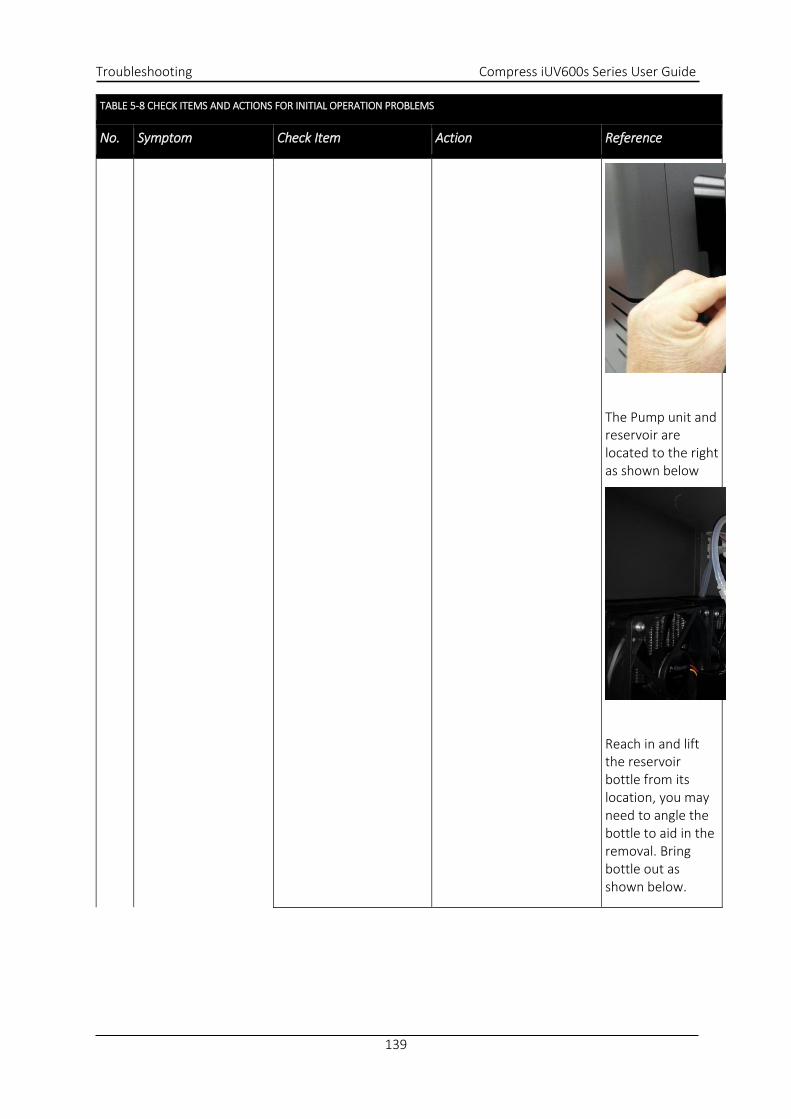
Troubleshooting Compress iUV600s Series User Guide
139
TABLE 5-8 CHECK ITEMS AND ACTIONS FOR INITIAL OPERATION PROBLEMS
No. Symptom Check Item Action Reference
The Pump unit and
reservoir are
located to the right
as shown below
Reach in and lift
the reservoir
bottle from its
location, you may
need to angle the
bottle to aid in the
removal. Bring
bottle out as
shown below.

Compress iUV6000s Series User Guide Troubleshooting
140
TABLE 5-8 CHECK ITEMS AND ACTIONS FOR INITIAL OPERATION PROBLEMS
No. Symptom Check Item Action Reference
You will notice a
green solution in
the bottle, this is
anti freeze, simply
fill the bottle ¾ full
with distilled
water, reattach
the lid and then
return bottle to
the original
location.
To Prime the LED
lamp cooling
system;
9- Release
the E stop
only, do
not power
up printer.
10- Raise the
machine
lid. You
should see
2x blue
LED’s illuminate
d.
11- Release
and move
carriage

Troubleshooting Compress iUV600s Series User Guide
141
TABLE 5-8 CHECK ITEMS AND ACTIONS FOR INITIAL OPERATION PROBLEMS
No. Symptom Check Item Action Reference
away from
the
capping
station as
per
picture
below. At
this point
you will
hear the
pump
running,
this means
that the
system
will be
starting to
prime,
look at the
cooling
tubes
connectin
g to the
lamps,
once the
air has
been
flushed
from the
tubing, the
system is
primed, at
the same
time
checking
for leaks,
allow the
pump to
continue
running
for the
entire 4
minutes
(cooling
down
period)
after

Compress iUV6000s Series User Guide Troubleshooting
142
TABLE 5-8 CHECK ITEMS AND ACTIONS FOR INITIAL OPERATION PROBLEMS
No. Symptom Check Item Action Reference
which the
pump will
automatic
ally stop.
Tubes
should be
solid and
NO air
visible.
12- Check the
reservoir
bottle and
ensure
that fluid
is visible

Troubleshooting Compress iUV600s Series User Guide
143
TABLE 5-8 CHECK ITEMS AND ACTIONS FOR INITIAL OPERATION PROBLEMS
No. Symptom Check Item Action Reference
Initial Ink Fill
Process - Colours
" p. 46
5 Though Ink reaches
head, ink is not
discharged from
head.
1. Is capping position
appropriate?
If ink inflow is
confirmed, execute
initial ink charge.
4.5.1
"Powerful Head
Cleaning" p.102
6
Ink is not discharged
though ink charge is
finished.
1. Are damper assembly,
ink tube / damper
connectors (K, Y, M,
C), manifold /tube
connectors securely
tightened?
Is O-ring properly
installed?
Check damper and
manifold
assemblies.
If ink inflow is confirmed,
execute initial ink charge.
4.5.1
"Powerful Head
Cleaning" p.102
2. Does shield part of
damper assembly
have air leak?
Replace damper
assembly and
check if cleaning
operation causes
ink inflow.
If ink inflow is
confirmed, execute
initial ink charge.
4.5.1
"Powerful Head
Cleaning" p.102
3. Is waste ink tube from
ink system assembly
bent / blocked /
kinked
Check for and
release kink / bend
in waste tube from
ink system
assembly (via
waste ink
compartment)
If ink inflow is
confirmed, execute
initial ink charge
4.5.1
"Powerful Head
Cleaning" p.102
Contact your
authorized
Compress
Distributor or

Compress iUV6000s Series User Guide Troubleshooting
144
TABLE 5-8 CHECK ITEMS AND ACTIONS FOR INITIAL OPERATION PROBLEMS
No. Symptom Check Item Action Reference
Technician for
further assistance

Troubleshooting Compress iUV600s Series User Guide
145
TABLE 5-8 CHECK ITEMS AND ACTIONS FOR INITIAL OPERATION PROBLEMS
No. Symptom Check Item Action Reference
7 Machine makes no
operations after
turned ON.
1. Turn machine OFF.
Disconnect mains
power, wait 5
minutes.
Turn it ON again and
check if the same
message appears.
If the message
appears: Contact
your authorized
Compress
Distributor or
Technician for
further assistance
2.5.2
"Switching the
Printer OFF." p.34
2.5.1
"Switching the
Printer ON" p.32
8 After turned ON,
machine displays
“initializing” and resets itself
1. Turn machine OFF.
Disconnect mains
power, wait 5
minutes.
Turn it ON again and
check if symptom is
repeated.
If the symptom is
repeated: Contact
your authorized
Compress
Distributor or
Technician for
further assistance
2.5.2
"Switching the
Printer OFF." p.34
2.5.1
"Switching the
Printer ON" p.32
9 Machine does not
perform initialization.
1. Turn machine OFF.
Disconnect mains
power, wait 5
minutes.
Turn it ON again and
check if symptom is
repeated.
If the symptom is
repeated: Contact
your authorized
Compress
Distributor or
Technician for
further assistance
2.5.2
"Switching the
Printer OFF." p.34
2.5.1
"Switching the
Printer ON" p.32
10 Machine does not
stop.
1. Turn machine OFF.
Disconnect mains
power, wait 5
minutes.
Turn it ON again and
check if symptom is
repeated.
If the symptom is
repeated: Contact
your authorized
Compress
Distributor or
Technician for
further assistance
2.5.2
"Switching the
Printer OFF." p.34
2.5.1
"Switching the
Printer ON" p.32
11 Operation panel
accepts no inputs
1. Turn machine OFF.
Disconnect mains
power, wait 5
minutes.
Turn it ON again and
check if symptom is
repeated.
If the symptom is
repeated: Contact
your authorized
Compress
Distributor or
Technician for
further assistance
2.5.2
"Switching the
Printer OFF." p.34
2.5.1
"Switching the
Printer ON" p.32
12 Machine prints
nothing though it
receives data
1. Turn machine OFF.
Disconnect mains
power, wait 5
minutes.
Turn it ON again and
check if symptom is
repeated.
If the symptom is
repeated: Contact
your authorized
Compress
Distributor or
Technician for
further assistance
2.5.2
"Switching the
Printer OFF." p.34
2.5.1
"Switching the
Printer ON" p.32

Compress iUV6000s Series User Guide Troubleshooting
146
5.3.3 Printing Problems
TABLE 5-9 SYMPTOMS, CHECK ITEMS AND ACTIONS FOR PRINTING PROBLEMS
No. Symptom Check Item Action Reference
1 Media feed after
printing is excessive
1. Turn machine OFF.
Disconnect mains
power, wait 5
minutes.
Turn it ON again and
check if symptom is
repeated.
If the symptom is
repeated: Contact
your authorized
Compress
Distributor or
Technician for
further assistance
2.5.2
"Switching the
Printer OFF."
p.34
2.5.1
"Switching the
Printer ON" p.32
2 Missing dots in
printing.
1. Perform cleaning
twice consecutively.
2.5.5
"Performing a
Head Clean from
the Operation
Panel" p.42
2. Is ink tube filled with
ink?
Perform initial ink
charge.
4.5.1
"Powerful Head
Cleaning" p.102
3. Perform “Print:Nozzle Check of printer self-
diagnosis or “Test Print”
If the nozzle check
patterns are
printed correctly,
refer to the action
in check item No.
4.
2.6.6
"Performing a
Nozzle Check
Test Print" p.55
4. If the symptom
persists: Contact
your authorized
Compress
Distributor or
Technician for
further assistance

Troubleshooting Compress iUV600s Series User Guide
147
TABLE 5-9 SYMPTOMS, CHECK ITEMS AND ACTIONS FOR PRINTING PROBLEMS
No. Symptom Check Item Action Reference
3 Blocked nozzles or ink
drops not eliminated
even after cleaning
1. Check cleaning wiper
condition
Clean the cleaning
wiper in accordance
with Section 4.4.3
"Cleaning the Wiper
and Head Cap" p.98.
After cleaning the
cleaning wiper,
perform cleaning
twice consecutively.
If cleaning wiper is
sticky with ink,
replace it with a
new one
4.4.3
"Cleaning the
Wiper and Head
Cap" p.98.
2. Is nozzle face
wiped/rubbed
correctly?
Check wiper
installation
condition and
secure it correctly.
3. Does residual ink
collect on print head
assembly or in nozzles?
Clean head as
follows.
Clean head
Perform initial ink charge
Check printouts again
2.5.5
"Performing a
Head Clean from
the Operation
Panel" p.42
4.5.1
"Powerful Head
Cleaning" p.102
4. Is waste ink tube from
ink system assembly
bent / blocked / kinked
Check for and
release kink / bend
in waste tube from
ink system assembly
(via waste ink
compartment) and
check if cleaning
operation causes
ink inflow
If ink inflow is
confirmed, execute
initial ink charge
4.5.1
"Powerful Head
Cleaning" p.102
5. If the symptom
persists: Contact
your authorized
Compress
Distributor or

Compress iUV6000s Series User Guide Troubleshooting
148
TABLE 5-9 SYMPTOMS, CHECK ITEMS AND ACTIONS FOR PRINTING PROBLEMS
No. Symptom Check Item Action Reference
Technician for
further assistance

Troubleshooting Compress iUV600s Series User Guide
149
TABLE 5-9 SYMPTOMS, CHECK ITEMS AND ACTIONS FOR PRINTING PROBLEMS
No. Symptom Check Item Action Reference
4
5
No printing
Particular color is
missing
1. Follow check items and
actions for symptom #3
(Blocked nozzles or ink
drops not eliminated
even after cleaning)
above
2. Are damper assembly,
ink tube / damper
connectors (K, Y, M, C),
manifold /tube
connectors securely
tightened?
Is O-ring properly
installed?
Check damper and
manifold assemblies
3. Does shield part of
damper assembly have
air leak?
Replace damper
assembly and check
if cleaning
operation causes
ink inflow.
If ink inflow is
confirmed, execute
initial ink charge.
4.5.1
"Powerful Head
Cleaning" p.102
4. If the symptom
persists: Contact
your authorized
Compress
Distributor or
Technician for
further assistance

Compress iUV6000s Series User Guide Troubleshooting
150
TABLE 5-9 SYMPTOMS, CHECK ITEMS AND ACTIONS FOR PRINTING PROBLEMS
No. Symptom Check Item Action Reference
6 Machine outputs all
solid colour printing.
2. Turn machine OFF.
Disconnect mains
power, wait 5 minutes.
Turn it ON again and
check if symptom is
repeated.
If the symptom is
repeated: Contact
your authorized
Compress Distributor
or Technician for
further assistance
2.5.2
"Switching the
Printer OFF." p.34
2.5.1
"Switching the
Printer ON" p.32
7
8
9
10
Blocky printing
quality.
Blocky image printing.
CR line seems dotted.
Missing lines in
printed output. (no
missing or ink
crooking in step
patterns in location
1G-7G in “Test Print”)
1. Is working environment
appropriate?
Use machine under
specified environment.
2.3.1
"Installation
Environment
Requirements"
p.28
2. Have you started
printing immediately
after initial charge?
Printing just after
initial charge may
cause following
symptoms.
Printed line blurs
Missing lines in print
In such cases, perform
cleaning two or three
times and check printout
again. If symptoms
remain even after
cleaning, leave machine
unused for 1 hour or
more. The perform
cleaning again and check
printout.
2.5.5
"Performing a
Head Clean from
the Operation
Panel" p.42
3. Check cleaning wiper
condition
Clean the cleaning
wiper in accordance
with Section 4.4.3
"Cleaning the Wiper
and Head Cap" p.98.
After cleaning the
cleaning wiper,
perform cleaning twice
consecutively.
If cleaning wiper is
sticky with ink, replace
it with a new one
4.4.3
"Cleaning the
Wiper and Head
Cap" p.98.

Troubleshooting Compress iUV600s Series User Guide
151
TABLE 5-9 SYMPTOMS, CHECK ITEMS AND ACTIONS FOR PRINTING PROBLEMS
No. Symptom Check Item Action Reference
7
8
9
10
4. Is nozzle face
wiped/rubbed
correctly?
Check wiper
installation condition
and secure it correctly.
5. Is CR encoder strip
contaminated?
If grease or dust
collect: Wipe strip with
a dry cloth.
If ink deposit presents:
Wipe it off with cloth
dampened with
neutral detergent.
If contamination or
deposit is too heavy:
Replace CR Encoder
Strip.
4.5.3 "Clean
the CR Encoder
Strip" p.110
6. Is waste ink tube from
ink system assembly
bent / blocked / kinked
Check for and release
kink / bend in waste
tube from ink system
assembly (via waste
ink compartment) and
check if cleaning
operation causes ink
inflow
If ink inflow is
confirmed, execute
initial ink charge
4.5.1
"Powerful Head
Cleaning" p.102
7. Does residual ink
collect on print head
assembly or in nozzles?
Clean head as follows.
Clean head
Perform initial ink
charge
Check printouts again
2.5.5
"Performing a
Head Clean from
the Operation
Panel" p.42
4.5.1
"Powerful Head
Cleaning" p.102
8. If the symptom
persists: Contact your
authorized Compress
Distributor or
Technician for further
assistance

Compress iUV6000s Series User Guide Troubleshooting
152
TABLE 5-9 SYMPTOMS, CHECK ITEMS AND ACTIONS FOR PRINTING PROBLEMS
No. Symptom Check Item Action Reference
11 Printout borders blur 1. Does powerful cleaning
correct symptom?
Perform powerful
cleaning twice
consecutively
4.5.1
"Powerful Head
Cleaning" p.102
2. Is the media height set
correctly.
Set the media height 2.6.5
"Checking media
height" p.53
3. If the symptom persists:
Contact your
authorized Compress
Distributor or
Technician for further
assistance
13
14
15
Many satellites
(Unnecessary dots)
Rough edges on
printout
Uneven lines (printed
with stains)
1. Is working environment
appropriate?
Use machine under
specified environment.
2.3.1
"Installation
Environment
Requirements"
p.28
2. Is CMYK ink pressure
sufficient? Is ink
pressure alarm
sounding?
Ensure all ink bottle
lids are secured tightly
3. Does powerful cleaning
correct symptom?
Perform powerful
cleaning twice
consecutively
4.5.1
"Powerful Head
Cleaning" p.102
4. Perform test printing. If nozzle check
patterns are printed
correctly, refer to
check item 6.
2.6.6
"Performing a
Nozzle Check
Test Print" p.55
5. Have you started
printing immediately
after initial charge?
Be sure to wait at least
1 hour after initial ink
charge. Print before
ink charge stabilization
will not provide
adequate printing
quality

Troubleshooting Compress iUV600s Series User Guide
153
TABLE 5-9 SYMPTOMS, CHECK ITEMS AND ACTIONS FOR PRINTING PROBLEMS
No. Symptom Check Item Action Reference
13
14
15
6. Check cleaning wiper
condition
Clean the cleaning
wiper in accordance
with Section 4.4.3
"Cleaning the Wiper
and Head Cap" p.98.
After cleaning the
cleaning wiper,
perform cleaning twice
consecutively.
If cleaning wiper is
sticky with ink, replace
it with a new one
4.4.3
"Cleaning the
Wiper and Head
Cap" p.98.
2.5.5
"Performing a
Head Clean from
the Operation
Panel" p.42
7. Is nozzle face
wiped/rubbed
correctly?
Check wiper
installation condition
and secure it correctly.
8. Is waste ink tube from
ink system assembly
bent / blocked / kinked
Check for and release
kink / bend in waste
tube from ink system
assembly (via waste
ink compartment) and
check if cleaning
operation causes ink
inflow
If ink inflow is
confirmed, execute
initial ink charge
4.5.1
"Powerful Head
Cleaning" p.102
9. Does residual ink
collect on print head
assembly or in nozzles?
Clean head as follows.
Clean head
Perform initial ink
charge
Check printouts again
2.5.5
"Performing a
Head Clean from
the Operation
Panel" p.42
4.5.1
"Powerful Head
Cleaning" p.102
10. If the symptom
persists: Contact your
authorized Compress
Distributor or
Technician for further
assistance

Compress iUV6000s Series User Guide Troubleshooting
154
TABLE 5-9 SYMPTOMS, CHECK ITEMS AND ACTIONS FOR PRINTING PROBLEMS
No. Symptom Check Item Action Reference
16 Mixed color lines are
not overlaid.
1. Are Bi-Directional
printing positions
aligned correctly?
Align Bi-Directional
printing positions.
2.6.8 "Bi-
Directional (Bi-
D) Adjustment"
p.58
2. Turn machine OFF.
Disconnect mains
power, wait 5 minutes.
Turn it ON again and
check if symptom is
repeated.
If the symptom is
repeated: Contact your
authorized Compress
Distributor or
Technician for further
assistance
2.5.2
"Switching the
Printer OFF."
p.34
2.5.1
"Switching the
Printer ON" p.32
17 Black and other colors
do not align.
1. Turn machine OFF.
Disconnect mains
power, wait 5 minutes.
Turn it ON again and
check if symptom is
repeated.
If the symptom is
repeated: Contact your
authorized Compress
Distributor or
Technician for further
assistance
2.5.2
"Switching the
Printer OFF."
p.34
2.5.1
"Switching the
Printer ON" p.32
18 White Ink layer is not
“thick” enough
1. Are all white ink nozzles
printing?
Perform Nozzle Check
Test Print.
Follow check items and
actions for symptoms
#3, 4 & 5 (Blocked
nozzles or ink drops not
eliminated even after
cleaning & Particular
color is missing) above
2.6.6
"Performing a
Nozzle Check
Test Print" p.55
2. White Ink settings in
RIP not set correctly refer to RIP
software user
guide
18 White Ink layer is not
“thick” enough
3. WIMS filter blocked Change WIMS filter. 4.6.4
"Replace WIMS
filter" p.115
19
Poor accuracy of
segment length in
head travel direct
(main scan direction).
4. Is working
environment
appropriate?
Use machine under
specified environment.
2.3.1
"Installation
Environment
Requirements"
p.28

Troubleshooting Compress iUV600s Series User Guide
155
TABLE 5-9 SYMPTOMS, CHECK ITEMS AND ACTIONS FOR PRINTING PROBLEMS
No. Symptom Check Item Action Reference
5. Is CR encoder strip
contaminated?
If grease or dust collect:
Wipe strip with a dry
cloth.
If ink deposit presents:
Wipe it off with cloth
dampened with neutral
detergent.
If contamination or
deposit is too heavy:
Replace CR Encoder
Strip.
4.5.3 "Clean
the CR Encoder
Strip" p.110
2. Turn machine OFF.
Disconnect mains
power, wait 5
minutes.
Turn it ON again and
check if symptom is
repeated.
If the symptom is
repeated: Contact your
authorized Compress
Distributor or
Technician for further
assistance
2.5.2
"Switching the
Printer OFF."
p.34
2.5.1
"Switching the
Printer ON" p.32
1. Is working
environment
appropriate?
Use machine under
specified environment.
2.3.1
"Installation
Environment
Requirements"
p.28

Compress iUV6000s Series User Guide Troubleshooting
156
TABLE 5-9 SYMPTOMS, CHECK ITEMS AND ACTIONS FOR PRINTING PROBLEMS
No. Symptom Check Item Action Reference
20
Poor linearity in
media feed direction
(media splicing
accuracy).
1. Are Bi-Directional
printing positions
aligned correctly?
Align Bi-Directional
printing positions.
2.6.8 "Bi-
Directional (Bi-
D) Adjustment"
p.58
2. Is CR encoder strip
contaminated?
If grease or dust collect:
Wipe strip with a dry
cloth.
If ink deposit presents:
Wipe it off with cloth
dampened with neutral
detergent.
If contamination or
deposit is too heavy:
Replace CR Encoder
Strip.
4.5.3 "Clean
the CR Encoder
Strip" p.110
3. Contact your
authorized Compress
Distributor or
Technician for further
assistance
21 Images print “out of registration” between white & colour layers
1. Are print settings in
the RIP correct?
Refer to the RIP User
Guide for correct
settings
2. Contact your
authorized Compress
Distributor or
Technician for further
assistance

Troubleshooting Compress iUV600s Series User Guide
157
TABLE 5-9 SYMPTOMS, CHECK ITEMS AND ACTIONS FOR PRINTING PROBLEMS
No. Symptom Check Item Action Reference
22 Nothing happens
when you send a print
job from the
computer
1. Is the printer turned
on?
Disengage the
emergency stop switch
Connect the power cord
to the socket at the rear
of the printer and to the
wall socket for mains
power
Ensure mains power
switch is ON
2.5.1
"Switching the
Printer ON" p.32
2. Message or Error on
the Control Panel
Check for message or
error display on the
control panel.
3. Is the printer
connected to the
computer via USB
cable?
Check USB cable
connection
2.5.3.2 "
Connecting USB
interface cable"
p.35
4. Observe Check Items
for Symptom # 23
“USB interface cannot establish
communication”
below
5. Error with RIP
program
Check error message in
RIP, resolve according
to RIP User Guide
refer to RIP
software user
guide /
computer user
guide
6. Is printer in Print
Ready State?
Contact your
authorized Compress
Distributor or
Technician for further
assistance
2.5 “Basic
Operations” p. 32
23 USB interface cannot
establish
communication.
1. Does computer in use
support USB?
Windows 95 does not
support USB officially.
Recommended
operating system
Windows XP or higher
-
2. Does the same error
occur even if you use
another USB port on
the computer?
Use another USB port
on the computer
-

Compress iUV6000s Series User Guide Troubleshooting
158
TABLE 5-9 SYMPTOMS, CHECK ITEMS AND ACTIONS FOR PRINTING PROBLEMS
No. Symptom Check Item Action Reference
23 USB interface cannot
establish
communication.
3. Are you using USB
hub?
Cascade connection
using USB hub is
available up to 5 stages.
If the printer operates
normally without the
USB hub, replace USB
hub.
Use USB hubs compliant
with USB2.0 Hi-Speed
standard.
-
4. Attempt
communication with
using another PC on
hand.
Replace USB cable.
-
5. Does the same error
occur even if interface
cable is changed?
Communication error
may be caused by an
open circuit in interface
cable or too long cable
length. Use cables
compliant with USB 2.0
Hi-Speed standard
-
6. Printer driver may be
defective
Update printer driver 0 "
Installing the
Printer Driver
(for USB
connection)"
p.76
7. Contact your
authorized Compress
Distributor or
Technician for further
assistance

Troubleshooting Compress iUV600s Series User Guide
159
TABLE 5-9 SYMPTOMS, CHECK ITEMS AND ACTIONS FOR PRINTING PROBLEMS
No. Symptom Check Item Action Reference
24 Printing position is
incorrect
1. Are settings from RIP
software correct?
Check RIP software
settings
refer to RIP
software user
guide
2. Printer driver may be
defective
Update printer driver 0 "
Installing the
Printer Driver
(for USB
connection)"
p.76
3. Contact your
authorized Compress
Distributor or
Technician for further
assistance

Compress iUV6000s Series User Guide Troubleshooting
160
TABLE 5-9 SYMPTOMS, CHECK ITEMS AND ACTIONS FOR PRINTING PROBLEMS
No. Symptom Check Item Action Reference
25
Some data are not
printed.
Some data prints as
“garbage”
1. Turn machine OFF.
Disconnect mains
power, wait 5
minutes.
Turn it ON again and
check if symptom is
repeated.
2.5.2
"Switching the
Printer OFF."
p.34
2.5.1
"Switching the
Printer ON" p.32
2. Re-start RIP program
/ computer
refer to RIP
software user
guide /
computer user
guide
3. Printer driver may be
defective
Update printer driver 0 "
Installing the
Printer Driver
(for USB
connection)"
p.76
4. Is CR encoder strip
contaminated?
If grease or dust collect:
Wipe strip with a dry
cloth.
If ink deposit presents:
Wipe it off with cloth
dampened with neutral
detergent.
If contamination or
deposit is too heavy:
Replace CR Encoder
Strip.
4.5.3 "Clean
the CR Encoder
Strip" p.110
5. Observe Check Items
for symptom #23 (USB
interface cannot
establish
communication)
above.
6. Contact your
authorized Compress
Distributor or
Technician for further
assistance

Troubleshooting Compress iUV600s Series User Guide
161
5.3.4 Noise Problems
TABLE 5-10 SYMPTOMS, CHECK ITEMS AND ACTIONS FOR NOISE PROBLEMS
No. Symptom Check Item Action Reference
1 Abnormal noise in
waiting mode
1. Are there any foreign
objects or obstacles at
noise-generating
position?
Remove obstacles and
foreign objects.
-
2. Is abnormal noise
heard from within the
machine?
Contact your authorized
Compress Distributor or
Technician for further
assistance
2 Abnormal noise is
heard while head is
moving laterally.
1. Contact your
authorized Compress
Distributor or
Technician for further
assistance
3 Beeper sound is heard
from right side of
printer.
1. Is Pressure Status
Light red?
Check CMYK ink bottle
lids to ensure they are
tight.
Check for air leaks or lack
of seal in the air
lines/ink bottles.
2. Is pressure status light
green
Contact your
authorized Compress
Distributor or
Technician for further
assistance

Compress iUV6000s Series User Guide Troubleshooting
162
5.3.5 Other Problems
TABLE 5-11 SYMPTOMS, CHECK ITEMS AND ACTIONS
No. Symptom Check Item Action Reference
1 Machine hangs up. 1. Turn machine OFF.
Disconnect mains
power, wait 5
minutes.
Turn it ON again and
check if symptom is
repeated.
If the symptom is
repeated: Contact your
authorized Compress
Distributor or
Technician for further
assistance
2.5.2
"Switching the
Printer OFF."
p.34
2.5.1
"Switching the
Printer ON"
p.32
2 Machine power is
shut off during
printing
1. Turn machine OFF.
Disconnect mains
power, wait 5
minutes.
Turn it ON again and
check if symptom is
repeated.
If the symptom is
repeated: Contact your
authorized Compress
Distributor or
Technician for further
assistance
2.5.2
"Switching the
Printer OFF."
p.34
2.5.1
"Switching the
Printer ON"
p.32
3 Ink spills out of waste
fluid container
1. Has waste fluid
container been
emptied (daily)
Empty waste fluid
container.
4.4.6
"Emptying the
waste ink
container"
p.101
2. Contact your
authorized Compress
Distributor or
Technician for further
assistance
4 Ink spills out of
flushing box.
1. Is flushing box clogged
with dust / dried ink
Remove dust.
Flush flushing box with
cleaning solution.
4.4.2
"Cleaning the
Flushing Tray"
p.97
2. Contact your
authorized Compress
Distributor or
Technician for further
assistance
5 Ink spills around
carriage rail.
1. Contact your
authorized Compress
Distributor or
Technician for further
assistance

Appendix Compress iUV600s Series User Guide
163
6. Appendix

Compress iUV600s Series User Guide Appendix
164
6.1 Product Specifications
6.1.1 Main Unit Specifications
Item Specifications
Model name iUV600s iUV600s-XL
Printing method Drop on-demand piezo
Motor driving method Firmware servo/DC motor drive
Media feeding method Fixed meshed gear and toothed belt
Media fixing method ACCULOK platen alignment and anchor system
Media supply and
ejection
Media load Front left push button for loading
Media eject Front left push button for ejecting
Media type Plastics, ceramics, board stock, metals, glass etc
Maximum loadable media length 440 mm / 17.5 inches 885mm / 35 inches
Maximum loadable media width 600mm / 24 inches 600 mm / 24 inches
Platen bed height adjustment 285mm (11.2”) I 150mm (5.9”)
I
TABLE 6-1 MAIN UNIT SPECIFICATIONS
6.1.2 Print Operation Specifications
Print direction Bidirectional Bidirectional Bidirectional Bidirectional Bidirectional
Ink skinning time <30 sec. <30 sec. <30sec. <30sec. <30sec.
Platen gap Auto set Auto set Auto set Auto set Auto set
Print image
Wave optional optional optional optional optional
Print image size Max A2 Max A2 Max A2 Max A2 Max A2
Print resolution - 720 ×
720dpi
1440 ×
720dpi
720 ×
1440dpi
720 ×
1440dpi
TABLE 6-2 PRINT OPERATION SPECIFICATIONS

Appendix Compress iUV600s Series User Guide
165
6.1.3 Printer physical specifications
Item Specifications
CPU 64Bit RISC CPU
Memory 256MB
Command MH-GL, MH-GL2, MH-RTL (RTL-PASS)
Interface • USB
(USB 1.1/2.0 is supported)
• Network Interface (10BASE-T/100BASE-TX)
Ink supply White W W W W Tube supply via pump from stirred bulk ink
container
Colour C M Y K Tube supply from pressurised bulk ink containers
Clear ink optional
Head life expectancy 2 billion dots per nozzle ( discharging ink at an operating
temperature of 25ºC (77F) with no dust)
Environmental conditions Temperature Humidity
Operation environment 18ºC (64F) to 30ºC (86F) 20% to 80%, with no
condensation
Printing accuracy warranty range 18ºC (64F) to 28ºC (82.4F) 40% to 60%, with no
condensation
Rate of change 2ºC/hour or less 5%/hour or less
Storage
environment
Without ink -10ºC (14F) to 60ºC (140F) 5% to 85%, with no
condensation
With ink 18ºC (64F) to 30ºC (86F) 20% to 85%, with no
condensation
Power source Voltage AC 90 - 132V or AC 200 – 240V (UV lamps are not variable and
must be set to correct voltage supply)
Frequency 50Hz/60Hz ±1Hz
Approximate
Power
consumption
During Printing 240W or less
During standby 80W or less
Internal Power
Supply
Fuse 6.3A, 250VAC, 5mm x 20mm, Type T
Approximate
Outer
Dimensions
Height 1200mm (47.2”)
Width 1210mm (47.6”)
Depth 1130mm (44.5”)
Approximate
Weight
Machine iUV600s 148 kg (326 lb.)
iUV600s-XL 168kg (370lb.)

Compress iUV600s Series User Guide Appendix
166
TABLE 6-3 PRINTER PHYSICAL SPECIFICATIONS

Appendix Compress iUV600s Series User Guide
167
6.2 Interface Specifications
This section explains the specification of the interfaces supported for this printer.
6.2.1 USB Interface Specifications TABLE 6-4 USB INTERFACE SPECIFICATIONS
Pin number Signal name Input/output Function
1 VCC - Cable power supply
2 - Data Bidirectional Data
3 + Data Bidirectional Data
4 Ground - Cable ground
TABLE 6-5 USB INTERFACE PIN / SIGNAL / FUNCTION
Item Specifications
Interface Universal Serial Bus Specifications Revision 2.0
Universal Serial Bus Device Class Definition for Plotting Devices Version 1.1
Data format NRZI
Transmission speed 480Mbps (High Speed Device)
Applicable connector USB Series B
Allowable cable
length
3 meters (9.8 foot) absolute maximum.
FIGURE 6-1 USB INTERFACE PIN
CONFIG

Compress iUV600s Series User Guide Appendix
168
6.2.2 Network Interface Specifications
Item Specifications
Network type Ethernet IEEE802.3
Network I/F 10BASE-T / 100BASE-TX Automatic transfer type
(RJ-45 connector twist pair cable ) MDI / MDI-X Automatic transfer
Corresponding
protocol
TCP/IP
TABLE 6-6 NETWORK INTERFACE SPECIFICATIONS
6.3 Options/Supplies List
6.3.1 Options
Name Model Sales units
Vacuum bed with venture ejector iUV600s and 600s/XL 1 box (includes
one unit)
Silicone stick down tacky mat iUV600s and 600s/XL 1 box (includes
one unit)
Rotary device iUV600s only 1 box (includes
one unit)
TABLE 6-7 OTHER OPTIONS
All options and supplies list above and below are designed specifically for Compress iUV600s series
printer use.
TIP

Appendix Compress iUV600s Series User Guide
169
6.3.2 Supplies
For more information about the following items, contact your local dealer:
Compress P70i ink
Compress P70i primers
Compress P70i maintenance solution
Compress polyester lint free cloths
Compress cleaning swabs
Wiper blade
WIMS filter
Capping station
Encoder strip
Solvent proof print head
Problems with printer operation may occur if cleaning products, media or inks other than those
recommended are used with the printer.
NOTE
CAUTION