user guide – basic functionality im/cm/b–en rev. q ... guide – basic functionality...
TRANSCRIPT

User Guide – Basic Functionality IM/CM/B–EN Rev. Q
ControlMaster CM10, CM30 and CM50Universal process controllers, 1/8, 1/4 and 1/2 DIN
The CompanyWe are an established world force in the design and manufacture of instrumentation for industrial process control, flow measurement, gas and liquid analysis and environmental applications.
As a part of ABB, a world leader in process automation technology, we offer customers application expertise, service and support worldwide.
We are committed to teamwork, high quality manufacturing, advanced technology and unrivalled service and support.
The quality, accuracy and performance of the Company’s products result from over 100 years experience, combined with a continuous program of innovative design and development to incorporate the latest technology.

Refer to Section 7.2, page 38 Refer to Section 7.3, page 41 Refer to Section 7.4, page 49
SeeBackCover
Refer to Section 6, page 28 Refer to Section 7.1, page 35
Loop 1 SetpointsLocal Setpoint 1 (4)RSP RatioRSP BiasRamp ModeRamp Rate
Loop 1 ControlOn/Off HysteresisModeAutotunePID
Loop 1 Time PropCycle Time 1Cycle Time 2
Alarm 1 (8)Trip
LanguageOperator Templates
Page 1 (4) TemplateOperator Functions
AutoscrollSoft Key FunctionAuto Manual EnableLocal Remote EnableAlarm Ack. EnableSP Adjust Enable
SettingsBrightnessContrast**
Analog InputsAnlg Input 1 (4)
Analog OutputsAnalog Output 1 (2)
Digital I/ODigital IO 1 (6)
RelaysRelay 1 (4)
Loop 1 SetpointsLow LimitHigh LimitNo. of Local SP’sLocal Setpoint 1Track ModeRSP RatioRSP BiasRSP Fault ActionDefault SetpointRamp ModeRamp RateSelect Sources
Loop 1 ControlControl TypeControl ActionOn/Off HysteresisAutotunePID
Loop 1 OutputLimitsFailure ActionsA/M Select SourcesSlew Rate
Loop 1 Split O/PMin Input 1Min OP 1Max Input 1Max OP 1Min Input 2Min OP 2Max Input 2Max OP 2
Loop 1 Time PropCycle Time 1Cycle Time 2
Basic Device Setup Display Input/Output ControlMenu
Exit Select
Initial SetupApp. TemplateLoop 1 Output TypeLoop 1 Split O/PInstrument TagMains Freq.Config ActionReset to Defaults
Security SetupBasic PasswordAdvanced PasswordReset Passwords
*When in Advanced Level (configuration) mode, press and hold the key to return to the standard Operator page – see Fig. 3.1, page 6**Enabled for CM30 and CM50 only
Basic Level *Advanced Level …
Menu
Exit Select
Menu
Exit Select
Menu
Exit Select
Menu
Exit Select

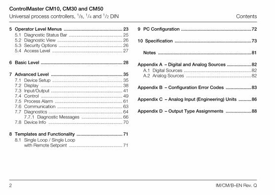
ControlMaster CM10, CM30 and CM50Universal process controllers, 1/8, 1/4 and 1/2 DIN Contents
IM/CM/B–EN Rev. Q 1
Contents
1 Safety .......................................................................... 31.1 Electrical Safety ..................................................... 31.2 Symbols ................................................................ 31.3 Health & Safety ..................................................... 4
2 Introduction ................................................................ 52.1 EC Directive 89/336/EEC ...................................... 52.2 End of Life Disposal ............................................... 5
3 Displays, Overview .................................................... 63.1 CM10 Operator Page, Icons & Keys ...................... 63.2 CM30 and CM50 Operator Page, Icons & Keys .... 7
4 Installation ................................................................... 94.1 Siting and Environmental Requirements ................. 94.2 Dimensions .......................................................... 104.3 Mounting ............................................................. 124.4 Jumper Links for Relay Outputs ........................... 13
4.4.1 Removing the Controller from its Case ...... 134.4.2 Resetting Jumper Links ............................. 14
4.5 Electrical Connections ......................................... 154.5.1 ControlMaster CM10
Electrical Connections ............................... 164.5.2 ControlMaster CM30
Electrical Connections ............................... 174.5.3 ControlMaster CM50
Electrical Connections ............................... 184.5.4 Analog Inputs ........................................... 194.5.5 Frequency / Pulse Input ............................. 214.5.6 Digital Input / Output ................................. 21
ControlMaster CM10, CM30 and CM50Universal process controllers, 1/8, 1/4 and 1/2 DIN Contents
2 IM/CM/B–EN Rev. Q
5 Operator Level Menus .............................................. 235.1 Diagnostic Status Bar .......................................... 255.2 Diagnostic View ................................................... 265.3 Security Options .................................................. 265.4 Access Level ....................................................... 27
6 Basic Level ................................................................ 28
7 Advanced Level ........................................................ 357.1 Device Setup ....................................................... 357.2 Display ................................................................ 387.3 Input/Output ........................................................ 417.4 Control ................................................................ 497.5 Process Alarm ..................................................... 617.6 Communication ................................................... 637.7 Diagnostics .......................................................... 64
7.7.1 Diagnostic Messages ................................ 667.8 Device Info .......................................................... 70
8 Templates and Functionality .................................... 718.1 Single Loop / Single Loop
with Remote Setpoint .......................................... 71
9 PC Configuration .......................................................72
10 Specification ............................................................73
Notes .........................................................................81
Appendix A – Digital and Analog Sources ...................82A.1 Digital Sources .....................................................82A.2 Analog Sources ...................................................82
Appendix B – Configuration Error Codes ....................83
Appendix C – Analog Input (Engineering) Units ..........86
Appendix D – Output Type Assignments ....................88
ControlMaster CM10, CM30 and CM50Universal process controllers, 1/8, 1/4 and 1/2 DIN 1 Safety
IM/CM/B–EN Rev. Q 3
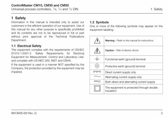
1 SafetyInformation in this manual is intended only to assist ourcustomers in the efficient operation of our equipment. Use ofthis manual for any other purpose is specifically prohibitedand its contents are not to be reproduced in full or partwithout prior approval of the Technical PublicationsDepartment.
1.1 Electrical SafetyThis equipment complies with the requirements of CEI/IEC61010-1:2001-2 'Safety Requirements for ElectricalEquipment for Measurement, Control and Laboratory Use'and complies with US NEC 500, NIST and OSHA. If the equipment is used in a manner NOT specified by theCompany, the protection provided by the equipment may beimpaired.
1.2 SymbolsOne or more of the following symbols may appear on theequipment labelling:
Warning – Refer to the manual for instructions
Caution – Risk of electric shock
Functional earth (ground) terminal
Protective earth (ground) terminal
Direct current supply only
Alternating current supply only
Both direct and alternating current supply
The equipment is protected through double insulation
ControlMaster CM10, CM30 and CM50Universal process controllers, 1/8, 1/4 and 1/2 DIN 1 Safety
4 IM/CM/B–EN Rev. Q
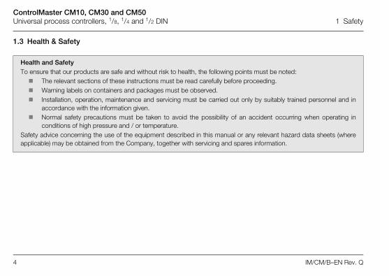
1.3 Health & Safety
Health and SafetyTo ensure that our products are safe and without risk to health, the following points must be noted: The relevant sections of these instructions must be read carefully before proceeding. Warning labels on containers and packages must be observed. Installation, operation, maintenance and servicing must be carried out only by suitably trained personnel and in
accordance with the information given. Normal safety precautions must be taken to avoid the possibility of an accident occurring when operating in
conditions of high pressure and / or temperature.Safety advice concerning the use of the equipment described in this manual or any relevant hazard data sheets (whereapplicable) may be obtained from the Company, together with servicing and spares information.

ControlMaster CM10, CM30 and CM50Universal process controllers, 1/8, 1/4 and 1/2 DIN 2 Introduction
IM/CM/B–EN Rev. Q 5
2 IntroductionThis manual provides details for the ControlMaster CM10 (1/8 DIN), CM30 (1/4 DIN) and CM50 (1/2 DIN) controllers with Basicfunctionality.
2.1 EC Directive 89/336/EECIn order to meet the requirements of the EC Directive 89/336/EEC for EMC regulations, this product must be used in an industrialenvironment.
2.2 End of Life DisposalControllers with Basic functionality do not contain any substance that causes undue harm to the environment and must bedisposed of in accordance with the Directive on Waste Electrical and Electronic Equipment (WEEE). They must not be disposedof in Municipal Waste Collection.
Note. Read all relevant sections of this guide before configuring the system or modifying system parameters.
Install and use associated equipment in accordance with the relevant national and local standards.
System configuration must be carried out only by users or personnel with approved access rights (user privileges).

ControlMaster CM10, CM30 and CM50Universal process controllers, 1/8, 1/4 and 1/2 DIN 3 Displays, Overview
6 IM/CM/B–EN Rev. Q
3 Displays, Overview
3.1 CM10 Operator Page, Icons & Keys
Fig. 3.1 ControlMaster CM10 Display and Icons
����
�����
���������
�����
��
�
�
�� ������ ��
�
��
PV Value
Setpoint Value
Icons
AccessLevel
Manual control Mode
Local Setpoint
Remote Setpoint
Output Value
Auto Control Mode
OperatorLevel
Icons
See Table 3.1 for key functions
ProcessAlarm
AutotuneMode
A Navigation (left) / Operator Level access key – see page 23.
B Up / Down keys – highlight menu items andincrease / decrease displayed values.
C Navigation key (right) / programmable Soft Key –see page 39.
Table 3.1 CM10 Front Panel Key Functions
Note. When a Soft Key option is assigned to key C,the Advanced Level (see page 35) must be accessedusing the Operator Level access key A.

ControlMaster CM10, CM30 and CM50Universal process controllers, 1/8, 1/4 and 1/2 DIN 3 Displays, Overview
IM/CM/B–EN Rev. Q 7
3.2 CM30 and CM50 Operator Page, Icons & KeysThe ControlMaster CM30 and CM50 displays and icons are shown in Fig. 3.2.
Fig. 3.2 ControlMaster CM30 and CM50 Displays and Icons
����
���� �
� �
��� ���� �
�� ����
����
����
�
�
�� ������ ��
����
��
��
�
�
�� ������ ��
��� ���� �
�� ���
PV Value
Bargraph
Setpoint Value
Icons
Access Level
ManualMode
Local Setpoint
RemoteSetpoint
Output Value
AutoMode
OperatorLevelMenu
Icons
Adjust– Indicates which value is
adjusted by the / keys
ProcessAlarm
Autotune
ControlMaster CM10, CM30 and CM50Universal process controllers, 1/8, 1/4 and 1/2 DIN 3 Displays, Overview
8 IM/CM/B–EN Rev. Q
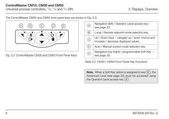
The ControlMaster CM30 and CM50 front panel keys are shown in Fig. 3.3.
Fig. 3.3 ControlMaster CM30 and CM50 Front Panel Keys
� � �� � A Navigation (left) / Operator Level access key – see page 23.
B Local / Remote setpoint mode selection key.
C Up / Down keys – navigate up / down menus and increase / decrease displayed values.
D Auto / Manual control mode selection key.
E Navigation key (right) / programmable Soft Key – see page 39.
Table 3.2 CM30 / CM50 Front Panel Key Functions
Note. When a Soft Key option is assigned to key E, theAdvanced Level (see page 35) must be accessed usingthe Operator Level access key A.

ControlMaster CM10, CM30 and CM50Universal process controllers, 1/8, 1/4 and 1/2 DIN 4 Installation
IM/CM/B–EN Rev. Q 9
4 Installation
4.1 Siting and Environmental Requirements
Fig. 4.1 Siting and Environmental Requirements
�
���� ���� ����
���� ����
At Eye Level Close to the SensorAvoid Vibration
Sensor
Temperature Limits
55°C (131°F)Max.
0°C (32°F)Min.
Humidity Limits
0 to 95% RH
IP66/NEMA4X (front panel) IP20 (rear panel)
Use Screened Cable
ControlMaster CM10, CM30 and CM50Universal process controllers, 1/8, 1/4 and 1/2 DIN 4 Installation
10 IM/CM/B–EN Rev. Q
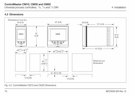
4.2 Dimensions
Fig. 4.2 ControlMaster CM10 and CM30 Dimensions
���� ����
Dimensions in mm (in.)
Panel Cut-outDimensions
97 (3.8)
97 (3.8)
121 (4.8)
141 (5.5)
91.8(3.6)
20 (0.8)
45 (1.8) +0.6–0
+0.02–0
92 (3.6)
+0.03–0
+0.8–092 (3.6)
14 (0.55)
30 (1.18)
14 (0.55)
+0.8–0
+0.03–0
50 (2.0)
ControlMaster CM10, CM30 and CM50Universal process controllers, 1/8, 1/4 and 1/2 DIN 4 Installation
IM/CM/B–EN Rev. Q 11
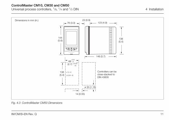
Fig. 4.3 ControlMaster CM50 Dimensions
Dimensions in mm (in.)
Controllers can be close-stacked to DIN 43835
144 (5.6)
123 (4.9)
146 (5.7)
138(5.4)
23 (0.9)
138 (5.4)
30 (1.18)
14 (0.55)
(+0.04 –0)
+1.0 –0
(+0.02–0)
+0.6–068
(2.7)
76 (3.0)

ControlMaster CM10, CM30 and CM50Universal process controllers, 1/8, 1/4 and 1/2 DIN 4 Installation
12 IM/CM/B–EN Rev. Q
4.3 MountingControlMaster is designed for panel mounting. For NEMA4Xprotection, a panel thickness of 2.5 mm (0.1 in.) is required. To panel-mount the controller:
1. Cut a hole of the correct size for the controller in thepanel – see section 4.2, page 10 for dimensions.
2. Insert the controller into the panel cut-out.Referring to Fig. 4.4:
3. Position the upper panel clamp A at the top front ofthe case against the panel.
4. Locate the panel clamp anchor B in slot C.5. Tighten the panel clamp anchor screw D until panel
clamp A is secured against the panel.
6. Repeat steps 3 to 5 to fit the lower panel clamp Eand panel clamp anchor F.
Caution. Do not overtighten the screw.
Fig. 4.4 Mounting Details
�
�
�
�
�
�

ControlMaster CM10, CM30 and CM50Universal process controllers, 1/8, 1/4 and 1/2 DIN 4 Installation
IM/CM/B–EN Rev. Q 13
4.4 Jumper Links for Relay OutputsThe factory-set default for relay action is N/O.
4.4.1 Removing the Controller from its CaseThe ControlMaster inner assembly must be removed from itscase to access the relay contact jumper links. Referring to Fig. 4.5:
1. Insert the bezel release tool A (supplied) into the frontpanel slot B below the function keys.
2. Press the bezel release tool A fully in and then downC until the shoulder on the tool engages with thenotch behind the controller front plate.
3. Pull the bezel release tool A to withdraw the innerassembly from the case D.
Note. If the bezel release tool is mislaid, 2 smallflat-headed screwdrivers (4 mm [0.15 in.]) can be used asalternative tools, one inserted into the front panel slot andthe second for leverage in the notch on the underside ofthe controller front plate. The notch is the only area thatcan be used as a leverage point – do not attempt to leverthe front panel from any other area.
Fig. 4.5 Removing the Controller from its Case
�
�
�
�
�

ControlMaster CM10, CM30 and CM50Universal process controllers, 1/8, 1/4 and 1/2 DIN 4 Installation
14 IM/CM/B–EN Rev. Q
4.4.2 Resetting Jumper Links
1. The links associated with the relay outputs are shownin Fig. 4.6.
2. If necessary, move the link to select the relay actionrequired (N/O or N/C).
Note. The factory-set default for all jumper links is N/O.
Fig. 4.6 Jumper Links for Relay Outputs
�� �
�� �
�� �
�
�
�
�
�
��
��
�
�
�
�
��
��
�
�
CM10 and CM30 Option Board 1 / 1a
CM50 Option Board 1
CM50 Standard Board 1
LK1 = Relay O/P 3 LK2 = Relay O/P 4
LK1 = Relay O/P 1 LK2 = Relay O/P 2
LK1 = Relay O/P 2 LK2 = Relay O/P 3LK3 = Relay O/P 4
ControlMaster CM10, CM30 and CM50Universal process controllers, 1/8, 1/4 and 1/2 DIN 4 Installation
IM/CM/B–EN Rev. Q 15
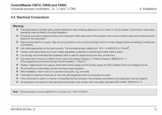
4.5 Electrical Connections
Warning. The instrument is not fitted with a switch therefore a disconnecting device such as a switch or circuit breaker conforming to local safety
standards must be fitted to the final installation.
It must be mounted in close proximity to the instrument within easy reach of the operator and must be marked clearly as the disconnectiondevice for the instrument.
Remove all power from supply, relay and any powered control circuits and high common mode voltages before accessing or making anyconnections.
Use cable appropriate for the load currents. The terminals accept cables from 18 to 14 AWG (0.8 to 2.5mm2).
Always route signal leads and power cables separately, preferably in earthed (grounded) metal conduit.
It is strongly recommended that screened cable is used for signal inputs and relay connections.
The instrument conforms to Mains Power Input Overvoltage Category 2, Pollution Degree 2 (EN601010–1). (This equipment is protected through double insulation – Class II.)
Analog / digital inputs and outputs, transmitter power supply and DC power supply are SELV (Safety Extra Low Voltage) circuits.
All connections to secondary circuits must have basic insulation. After installation, there must be no access to live parts, e.g. terminals.
Terminals for external circuits are for use only with equipment with no accessible live parts.
If the instrument is used in a manner not specified by the Company, the protection provided by the equipment may be impaired.
All equipment connected to the instrument's terminals must comply with local safety standards (IEC 60950, EN601010–1).
Note. Terminal screws must be tightened to a torque of 0.1 Nm (0.9 lbf/in.).
ControlMaster CM10, CM30 and CM50Universal process controllers, 1/8, 1/4 and 1/2 DIN 4 Installation
16 IM/CM/B–EN Rev. Q
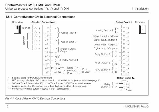
4.5.1 ControlMaster CM10 Electrical Connections
Fig. 4.7 ControlMaster CM10 Electrical Connections
�
�
�
�
�
�
�
�
��
��
��
�
��
��
��
��
��
�
�
�
�
�
�
�
�
�
� ��
��
��
��
�
��
��
��
��
��
��
�
��
��
Option Board 1C
omm
s*
Tx PSU
Analog / Digital Output 1****
Analog Input 1
Analog Input 2
Relay Output 1
NeutralLine*** 100 to
240 V AC10 W
10 to 36 VDC
NCCNO
Analog Output 2
Digital Input / Output 1
Digital Input / Output 2
Digital Input / Output –
Relay Output 2
Relay Output 3
Relay Output 4
Digital Output + External
**C
**C
**C
Standard Connections
* See rear panel for MODBUS connections** N/O (factory default) or N/C contact selection made via internal jumper links – see page 13*** 200 mA Type T fuse (mains AC) or 2 A Type T fuse (120 V DC max.) and external
isolating switch. For UL-marked controllers the fuse must be UL recognized.**** Provides 24 V digital output (observe + and – connections)
Rear View Rear View
RelayOutput 2
**C
Option Board 1a
ControlMaster CM10, CM30 and CM50Universal process controllers, 1/8, 1/4 and 1/2 DIN 4 Installation
IM/CM/B–EN Rev. Q 17
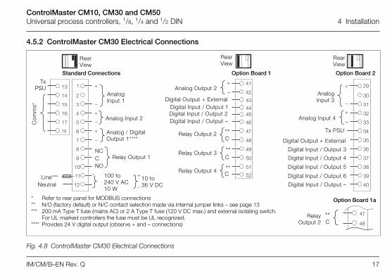
4.5.2 ControlMaster CM30 Electrical Connections
Fig. 4.8 ControlMaster CM30 Electrical Connections
�
�
�
�
�
�
�
�
��
��
��
�
��
��
��
��
��
�
�
�
�
�
�
�
�
�
� ��
�
�
�
�
�
�
�
�
�
��
�
�
�
� ��
��
�
����
��
��
��
��
��
��
��
��
��
Rear View
AnalogInput 3
Analog Input 4
Tx PSU
Digital Output + ExternalDigital Input / Output 1
Digital Input / Output 4
Digital Input / Output 5
Digital Input / Output 6
Digital Input / Output –
Com
ms*
TxPSU Analog Output 2
RearView
Option Board 1 Option Board 2Standard Connections
Digital Input / Output 2Digital Input / Output –
**C
**C
**C
Relay Output 2
Relay Output 3
Relay Output 4
Digital Output + External
Digital Input / Output 3
Analog Input 1
Analog Input 2
Relay Output 1
NeutralLine*** 100 to
240 V AC10 W
10 to 36 V DC
NCCNO
Analog / Digital Output 1****
RearView
* Refer to rear panel for MODBUS connections** N/O (factory default) or N/C contact selection made via internal jumper links – see page 13*** 200 mA Type T fuse (mains AC) or 2 A Type T fuse (120 V DC max.) and external isolating switch.
For UL-marked controllers the fuse must be UL recognized.**** Provides 24 V digital output (observe + and – connections)
**C
RelayOutput 2
Option Board 1a

ControlMaster CM10, CM30 and CM50Universal process controllers, 1/8, 1/4 and 1/2 DIN 4 Installation
18 IM/CM/B–EN Rev. Q
4.5.3 ControlMaster CM50 Electrical Connections
Fig. 4.9 ControlMaster CM50 Electrical Connections
�
�
�
�
�
�
�
�
�
�
��
��
��
�
��
��
��
��
��
�
�
�
�
� ��
��
��
��
��
��
�
�
�
�
�
�
�
�
��
��
��
��
�
�
�
�
�
��
��
� �
�
�
�
Rear View Rear View
Digital Output + External
Tx PSU
Digital Input / Output 5Digital Input / Output 6Digital Input / Output –
Digital Input / Output 3Digital Input / Output 4
Relay Output 3
Relay Output 4
Analog Output 2
Option Board 1
**C
**C
Analog Input 1
Analog Input 2
Com
ms*
Standard Connections
NeutralLine*** 100 to
240 V AC10 W
10 to 36 V DC
Digital Output + ExternalDigital Input / Output 1Digital Input / Output 2
Digital Input / Output –
Analog / Digital Output 1****
Relay Output 1
Relay Output 2
**C
**C
Tx PSU*Refer to rear panel for MODBUS connections
**N/O (factory default) or N/C contact selection made via internal jumper links – see page 13
***200 mA Type T fuse (mains AC) or 2 A Type T fuse (120 V DC max.) and external isolating switch. For UL-marked controllers the fuse must be UL recognized.
****Provides 24 V digital output (observe + and – connections)
Analog Input 3
Analog Input 4
ControlMaster CM10, CM30 and CM50Universal process controllers, 1/8, 1/4 and 1/2 DIN 4 Installation
IM/CM/B–EN Rev. Q 19
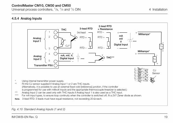
4.5.4 Analog Inputs
Fig. 4.10 Standard Analog Inputs (1 and 2)
mA mVV
Digital Input
Milliamps*
THC
CJ**
THC***
3-lead RTD
mA, mV, V,Digital Input
2-lead RTD+ Resistance
RTD +
RTD –
RTD +
RTD –
Transmitter PSU
AnalogInput 2
AnalogInput 1
Milliamps*
RTD –3rd lead
CJ Sensor
* Using internal transmitter power supply.** Fit the CJ sensor supplied if Analog Input 1 or 2 are THC inputs.
(Alternatively, it is possible to use an external fixed cold [reference] junction, if the controller is programmed for use with millivolt inputs and the appropriate thermocouple linearizer is selected.)
*** Analog Input 2 can be used only with THC inputs if Analog Input 1 is also used as a THC input.**** For mA input types, to ensure loop continuity when the controller is switched off, fit a 2V7 Zener diode as shown.Note. 3-lead RTD: 3 leads must have equal resistance, not exceeding 20 each.
****
****

ControlMaster CM10, CM30 and CM50Universal process controllers, 1/8, 1/4 and 1/2 DIN 4 Installation
20 IM/CM/B–EN Rev. Q
Fig. 4.11 ControlMaster CM30 and CM50 Optional Analog Inputs (3 and 4)
* Using internal transmitter power supply.** Fit the CJ sensor supplied if Analog Inputs 3 or 4 are THC inputs.
(Alternatively, it is possible to use an external fixed cold [reference] junction, if the controller is programmed for use with millivolt inputs and the appropriate thermocouple linearizer is selected.)
*** Analog Input 4 can be used only with THC inputs if Analog Input 3 is also used as a THC input.**** For mA input types, to ensure loop continuity when the controller is switched off, fit a 2V7 Zener diode as shown.Note. 3 Leads must have equal resistance, not exceeding 20 W each.
mA mVV
Digital Input
Milliamps*
THC
CJ**
THC***
3-lead RTD
mA, mV, V,Digital Input
2-lead RTD + Resistance
RTD +
RTD –
RTD +
RTD –
Transmitter PSU
AnalogInput 4
AnalogInput 3
Milliamps*
RTD –3rd lead
CM30 CM50
CJ Sensor
****
****
ControlMaster CM10, CM30 and CM50Universal process controllers, 1/8, 1/4 and 1/2 DIN 4 Installation
IM/CM/B–EN Rev. Q 21
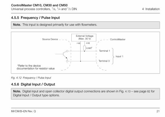
4.5.5 Frequency / Pulse Input
4.5.6 Digital Input / Output
Note. This input is designed primarily for use with flowmeters.
Fig. 4.12 Frequency / Pulse Input
Note. Digital input and open collector digital output connections are shown in Fig. 4.13 – see page 82 for Digital Input / Output type options.
Terminal 1
Terminal 3
Source DeviceExternal Voltage
(Max. 30 V) ControlMaster
Input 1
–ve +ve
Load*
*Refer to the device documentation for resistor value

ControlMaster CM10, CM30 and CM50Universal process controllers, 1/8, 1/4 and 1/2 DIN 4 Installation
22 IM/CM/B–EN Rev. Q
Fig. 4.13 Digital Input and Open Collector Digital Output Connections
+ve
–ve
Load
Digital Input/Output + ExternalCM10: Terminal 21
CM30: Terminal 43 or 35CM50: Terminal 7 or 30
Digital Input/OutputCM10: Terminal 22 or 23
CM30: Terminal 44 or 45; 36, 37, 38 or 39CM50: Terminal 8 or 9; 31, 32, 33 or 34
Digital Input/Output –CM10: Terminal 24
CM30: Terminal 46 or 40CM50: Terminal 10 or 35
Terminal Connections on Standard and Option Boards
External Voltage (Max. 30 VDC)
24 VDC Input OR
Digital Input/OutputCM10: Terminal 22 or 23
CM30: Terminal 44 or 45; 36, 37, 38 or 39CM50: Terminal 8 or 9; 31, 32, 33 or 34
Digital Input/Output –CM10: Terminal 24
CM30: Terminal 46 or 40CM50: Terminal 10 or 35
+ve
–ve

ControlMaster CM10, CM30 and CM50Universal process controllers, 1/8, 1/4 and 1/2 DIN 5 Operator Level Menus
IM/CM/B–EN Rev. Q 23
5 Operator Level Menus
Operator level menus are used to adjust setpoint(s) and output(s),select setpoints, select the view and to enter Basic and Advancedmodes (via the Access level) – see page 27.To access Operator Level menus:
1. From the Operator Page, press to view the available menus.2. Use the / keys to scroll through the menus and menu
options.3. Press to expand menu levels and to select menu options or
press to return to the previous menu.
Menu functions are described in Table 5.1 page 24.
������������
��
������������
�����
�����
�Adjust... Setpoint Loop 1View SelectEnter Config. Mode
ControlMaster CM10, CM30 and CM50Universal process controllers, 1/8, 1/4 and 1/2 DIN 5 Operator Level Menus
24 IM/CM/B–EN Rev. Q
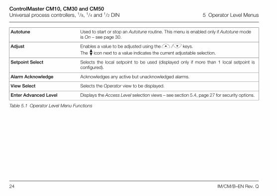
Autotune Used to start or stop an Autotune routine. This menu is enabled only if Autotune modeis On – see page 30.
Adjust Enables a value to be adjusted using the / keys.The icon next to a value indicates the current adjustable selection.
Setpoint Select Selects the local setpoint to be used (displayed only if more than 1 local setpoint isconfigured).
Alarm Acknowledge Acknowledges any active but unacknowledged alarms.
View Select Selects the Operator view to be displayed.
Enter Advanced Level Displays the Access Level selection views – see section 5.4, page 27 for security options.
Table 5.1 Operator Level Menu Functions

ControlMaster CM10, CM30 and CM50Universal process controllers, 1/8, 1/4 and 1/2 DIN 5 Operator Level Menus
IM/CM/B–EN Rev. Q 25
5.1 Diagnostic Status Bar
Fig. 5.1 ControlMaster Diagnostic Status Bar (ControlMaster CM30 Shown)
���������������������
��
���������
������
�����
����������
Description of diagnostic or alarm tag.
The highest priority diagnostic or alarm is displayed. Other active diagnostic / alarm states can be viewed on the Diagnostic View –
see page 26.
Failure
Maintenance
Out of Spec
Check Function
NAMUR (NE107) Status Icon
High Process Alarm
Low Process Alarm
High Latch Alarm
Low Latch Alarm

ControlMaster CM10, CM30 and CM50Universal process controllers, 1/8, 1/4 and 1/2 DIN 5 Operator Level Menus
26 IM/CM/B–EN Rev. Q
5.2 Diagnostic ViewThe Diagnostic View can be selected from the Operator /View Select menu. All currently active diagnostic alarm statesare displayed in the Diagnostic View.
5.3 Security OptionsPasswords can be set to enable secure end-user access at2 levels: Basic and Advanced. A Service level is also listed,this is password-protected at the factory and reserved forfactory use only.Passwords are set, changed or restored to their defaultsettings at the Device Setup / Security Setup parameter – seepage 37.
Fig. 5.2 ControlMaster Diagnostic View (ControlMaster CM30 Shown)
����
� ���������������������
��������
��������
Alarm Icon Diagnostic Description / Alarm Tag
Note. When the controller is powered-up for the firsttime the Basic and Advanced level levels can beaccessed without password protection. Protectedaccess to these levels must be allocated on-site asrequired.

ControlMaster CM10, CM30 and CM50Universal process controllers, 1/8, 1/4 and 1/2 DIN 5 Operator Level Menus
IM/CM/B–EN Rev. Q 27
5.4 Access Level
Level Access
Logout Displayed after Basic or Advanced level areaccessed. Logs the user out of Basic orAdvanced level. If passwords are set, apassword must be entered to access theselevels again after selecting Logout.
Read Only Enables all parameter settings to be viewed asread-only parameters.
Basic Enables access to the Basic level andadjustment of PID parameters, autotuningconfiguration and adjustment of alarm trippoints.
Advanced Enables configuration access to all parameters.
Service Reserved for use by authorized servicepersonnel.
Table 5.2 Access Levels
Fig. 5.3 Access Level
Note. A 5-minute time-out period enables a user to returnto the Operator page and re-access the previous menu(displayed at exit) without re-entering the password. Forperiods over 5-minutes (or if Logout is selected), apassword must be re-entered to access protected levels.
������������
��
������������
�����
�����
�
Access Level
Back Select
Advanced
Logout
Basic
Service
Read Only
Select Enter Config. Mode
Select Access Level Icon
To view Access Level
ControlMaster CM10, CM30 and CM50Universal process controllers, 1/8, 1/4 and 1/2 DIN 6 Basic Level
28 IM/CM/B–EN Rev. Q
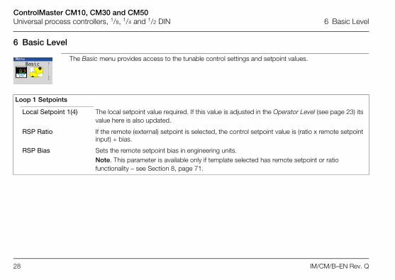
6 Basic Level
The Basic menu provides access to the tunable control settings and setpoint values.MenuBasic
Loop 1 Setpoints
Local Setpoint 1(4) The local setpoint value required. If this value is adjusted in the Operator Level (see page 23) itsvalue here is also updated.
RSP Ratio If the remote (external) setpoint is selected, the control setpoint value is (ratio x remote setpointinput) + bias.
RSP Bias Sets the remote setpoint bias in engineering units.Note. This parameter is available only if template selected has remote setpoint or ratio functionality – see Section 8, page 71.

ControlMaster CM10, CM30 and CM50Universal process controllers, 1/8, 1/4 and 1/2 DIN 6 Basic Level
IM/CM/B–EN Rev. Q 29
…Basic / …Loop 1 Setpoints
Ramp Mode The ramping setpoint facility can be used toprevent a large disturbance to the controloutput when the setpoint value is changed.The rate set applies to both the local and theremote setpoints.
Ramp Rate Sets the ramp rate required in engineering units / hour.Note. Applicable only if Ramp Mode is On.
Loop 1 Control
On / Off Hysteresis Sets the hysteresis value in engineering units.
Note. Applicable only if Control Type is On / Off – see page 53.
�
���
���
�� ��
Displayed Local Setpoint Value
Time
Actual(Ramping) Setpoint Value
used by PID Algorithm*
*Example: Ramp Rate = 200 Increments / hr
1 Hour
PVPV
ONOFF
Reverse Acting Control Output
Setpoint
HysteresisValue
HysteresisValue
Setpoint
Direct Acting Control Output
ONOFF

ControlMaster CM10, CM30 and CM50Universal process controllers, 1/8, 1/4 and 1/2 DIN 6 Basic Level
30 IM/CM/B–EN Rev. Q
…Basic / …Loop 1 Control
Mode Turns the Autotune functionality on or off. When set to On, an Autotune can be started from theOperator level menus – see page 23.
Autotune Note. Autotune is enabled only if the control type is PID – see page 32.
Autotune is a user-activated feature that enables automatic setting of the controller PID parameters using an 'at setpoint'type algorithm. Autotune changes the controller output and then monitors the process response to calculate the optimumPID settings. Autotune uses a relay type function with hysteresis that initiates a controlled oscillation in the process. NewPID parameters are calculated and stored in the controller automatically.Note. To achieve the best results from Autotune, switch the controller to Manual control mode (see page 6) and adjust the output until the PV is stable (close to the normal setpoint) before initiating Autotune.
ControlMaster CM10, CM30 and CM50Universal process controllers, 1/8, 1/4 and 1/2 DIN 6 Basic Level
IM/CM/B–EN Rev. Q 31
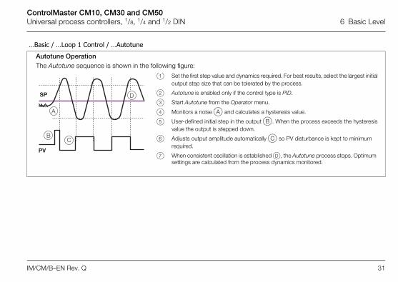
…Basic / …Loop 1 Control / …Autotune
Autotune OperationThe Autotune sequence is shown in the following figure:
�
��
�SP
PV
1 Set the first step value and dynamics required. For best results, select the largest initialoutput step size that can be tolerated by the process.
2 Autotune is enabled only if the control type is PID.
3 Start Autotune from the Operator menu.
4 Monitors a noise A and calculates a hysteresis value.
5 User-defined initial step in the output B. When the process exceeds the hysteresisvalue the output is stepped down.
6 Adjusts output amplitude automatically C so PV disturbance is kept to minimum required.
7 When consistent oscillation is established D, the Autotune process stops. Optimum settings are calculated from the process dynamics monitored.
ControlMaster CM10, CM30 and CM50Universal process controllers, 1/8, 1/4 and 1/2 DIN 6 Basic Level
32 IM/CM/B–EN Rev. Q
…Basic / …Loop 1 Control / …Autotune
First Step Defines the maximum size of the first output step in the autotuning process. Autotune adjuststhe output step magnitude according to the process noise and response to provide a reliablemeasurement of the process characteristics with the minimum disturbance of the process. Themaximum setting provides the largest output step possible from the current output value.
Dynamics Used to configure Autotune to give optimum results according to the type of process beingcontrolled.
Normal Determines if derivative control is required automatically and calculates the control settingsaccordingly.
Deadtime Sets the proportional and integral terms to give optimum control for the deadtime process(higher proportional band [lower gain] and shorter integration time).
PI Used for processes where it is known that derivative control is not required.
Reset If the controller is transferred to another process or duty, Autotune must be reset. The currentPID (see page 32) settings are retained but the internal process data is cleared ready for acompletely new process with different characteristics.
PID The controller’s PID (proportional, integral and derivative control) settings can be commissionedusing the Autotune (see page 30) function and / or they can be adjusted manually.
Proportional Band 1 Set as % of engineering range.
Integral Time 1 Set in seconds per repeat. To turn integral action off, set to 0 or 10000 s.
Derivative Time 1 Set in seconds.
ControlMaster CM10, CM30 and CM50Universal process controllers, 1/8, 1/4 and 1/2 DIN 6 Basic Level
IM/CM/B–EN Rev. Q 33
…Basic / …Loop 1 Control / …PID
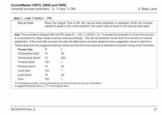
Manual Reset When the Integral Time is Off, the manual reset parameter is activated. When the processvariable is equal to the control setpoint, the output value is equal to the manual reset value.
Note: The controller is shipped with null PID values (P = 100, I = off & D = 0). To enable the controller to control the process it is connected to, these values must be tuned accordingly. This can be achieved via the AutoTune function or manual adjustment. If the controller is tuned manually the table below provides details of some suggested values to start from.These values are only suggested starting values and should not be used as an alternative to proper tuning of the Controller.
Process Type P I
Temperature (fast)* 10 30
Temperature (slow)* 10 300
Pressure (fast) 100 1
Pressure (slow) 10 30
Level (fast) 100 1
Level (slow) 10 30
Flow 100 1
*For temperature loops, control performance can be improved via the use of Derivative. A suggested starting value is 1/6th of the Integral value.
ControlMaster CM10, CM30 and CM50Universal process controllers, 1/8, 1/4 and 1/2 DIN 6 Basic Level
34 IM/CM/B–EN Rev. Q
…Basic
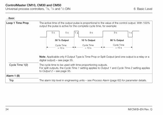
Loop 1 Time Prop The active time of the output pulse is proportional to the value of the control output. With 100%output the pulse is active for the complete cycle time, for example:
Note. Applicable only if Output Type is Time Prop or Split Output (and one output is a relay or a digital output) – see page 35.
Cycle Time 1(2) The cycle time to be used with time proportioning outputs. For split outputs, the Cycle Time 1 setting applies to Output 1 and Cycle Time 2 setting appliesto Output 2 – see page 35.
Alarm 1 (8)
Trip The alarm trip level in engineering units – see Process Alarm (page 62) for parameter details.
Cycle Time= 10 s
Cycle Time= 10 s
Cycle Time= 10 s
50 % Output 10 % Output 90 % Output
5 s 5 s 1 s 1 s9 s 9 s
ControlMaster CM10, CM30 and CM50Universal process controllers, 1/8, 1/4 and 1/2 DIN 7 Advanced Level
IM/CM/B–EN Rev. Q 35
7 Advanced Level
7.1 Device Setup
Provides access to standard setup parameters to determine the type of control / indication required. Also provides the ability to create non-standard configurations for special application requirements.
MenuDevice Setup
Initial Setup
App Template Application templates enable configurations for particular applications to be created assimply as possible. Select the appropriate template before configuring any otherparameters. When a template is selected, the Controller assumes the preset form forthat template. The inputs and function blocks are soft-wired automatically to perform theselected function.Note. See Section 8, page 71 for templates available to ControlMasters with Basic functionality.
Loop 1 Output Type The appropriate output function block, relay, digital and analog outputs are configured andsoft wired – see Appendix D, page 88 for output assignments.
ControlMaster CM10, CM30 and CM50Universal process controllers, 1/8, 1/4 and 1/2 DIN 7 Advanced Level
36 IM/CM/B–EN Rev. Q
…Device Setup / …Basic Setup
Loop 1 Split O/P These types of outputs split the Control (PID) output signal (see page 32) into 2 signals. Thelinear relationship between the PID output and the 2 outputs can be configured in thecontrol configuration.
Instrument Tag A 16-character alphanumeric tag, displayed on Operator pages.
Mains Freq Used to set the internal filters to reduce mains power frequency interference.
Config Action The Config Action parameter is used to determine how the controller and controller outputsbehave when the Advanced level is entered – see page 35.
Continue The controller continues to operate as in Operator level. Outputs continue to operate asnormal.
Hold Puts the controller into Manual control mode. When the Configuration level is exited, thecontroller returns to the pre-Configuration mode of operation. Digital, relay and analogoutputs are held at their value / state when Configuration mode is entered.
Inactive Puts the controller into Manual control mode. When the Advanced level is exited, thecontroller returns to the pre-configuration mode of operation.
Digital and relay outputs are turned off. Analog outputs are set to 0 mA.
Reset to Defaults Resets all configuration parameters to their default values.
ControlMaster CM10, CM30 and CM50Universal process controllers, 1/8, 1/4 and 1/2 DIN 7 Advanced Level
IM/CM/B–EN Rev. Q 37
…Device Setup
Security Setup 2 Security access levels are provided, each protected by a password of up to 6alphanumeric characters.Note. Passwords are not set at the factory and must be entered by the end user(s).
Basic Password Basic level provides access to the Basic level – see section 6, page 28.
Advanced Password Provides access to all configuration parameters – see section 5.4, page 27.
Reset Passwords Resets all passwords to factory values.

ControlMaster CM10, CM30 and CM50Universal process controllers, 1/8, 1/4 and 1/2 DIN 7 Advanced Level
38 IM/CM/B–EN Rev. Q
7.2 Display
Used to setup the operator page, displayed language and display hardware settings.
Language Selects the language on the controller's local display.
Operator Templates Enables up to 4 operator pages to be configured to suit the application requirements.
Page 1 (to 4) Template The operator template type.
The functions available in each template type are displayed as abbreviations, for example:Single PV, SP & OP
Key to abbreviations:
PV = process variable SP = setpoint OP = control output
MenuDisplay
ControlMaster CM10, CM30 and CM50Universal process controllers, 1/8, 1/4 and 1/2 DIN 7 Advanced Level
IM/CM/B–EN Rev. Q 39
…Display
Operator Functions
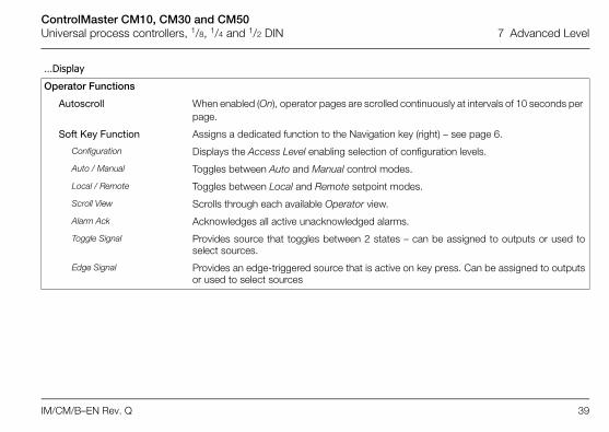
Autoscroll When enabled (On), operator pages are scrolled continuously at intervals of 10 seconds per page.
Soft Key Function Assigns a dedicated function to the Navigation key (right) – see page 6.
Configuration Displays the Access Level enabling selection of configuration levels.
Auto / Manual Toggles between Auto and Manual control modes.
Local / Remote Toggles between Local and Remote setpoint modes.
Scroll View Scrolls through each available Operator view.
Alarm Ack Acknowledges all active unacknowledged alarms.
Toggle Signal Provides source that toggles between 2 states – can be assigned to outputs or used toselect sources.
Edge Signal Provides an edge-triggered source that is active on key press. Can be assigned to outputsor used to select sources

ControlMaster CM10, CM30 and CM50Universal process controllers, 1/8, 1/4 and 1/2 DIN 7 Advanced Level
40 IM/CM/B–EN Rev. Q
…Display /…Operator Enable Functions
Auto Manual Enable Turns on / off the ability for Auto / Manual control mode to be changed in Operator Level.
Local Remote Enable Turns on / off the ability for local / remote setpoint mode to be changed in Operator Level.
Alarm Ack. Enable Turns on / off the ability to acknowledge alarms from the front panel.
SP Adjust Enable Turns on / off setpoint adjustment in the Operator Level.
Settings Adjusts display settings to suit ambient conditions.
Brightness Increases / Decreases the display brightness to suit local environmental conditions.
Contrast Increases / Decreases the display contrast to suit local environmental conditions (enabledfor CM30 and CM50 only).
ControlMaster CM10, CM30 and CM50Universal process controllers, 1/8, 1/4 and 1/2 DIN 7 Advanced Level
IM/CM/B–EN Rev. Q 41
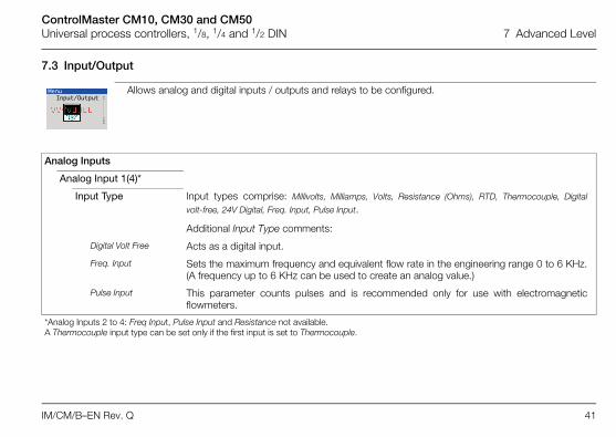
7.3 Input/Output
Allows analog and digital inputs / outputs and relays to be configured.
Analog Inputs
Analog Input 1(4)*
Input Type Input types comprise: Millivolts, Milliamps, Volts, Resistance (Ohms), RTD, Thermocouple, Digital
volt-free, 24V Digital, Freq. Input, Pulse Input.
Additional Input Type comments:
Digital Volt Free Acts as a digital input.
Freq. Input Sets the maximum frequency and equivalent flow rate in the engineering range 0 to 6 KHz.(A frequency up to 6 KHz can be used to create an analog value.)
Pulse Input This parameter counts pulses and is recommended only for use with electromagneticflowmeters.
*Analog Inputs 2 to 4: Freq Input, Pulse Input and Resistance not available. A Thermocouple input type can be set only if the first input is set to Thermocouple.
MenuInput/Output
ControlMaster CM10, CM30 and CM50Universal process controllers, 1/8, 1/4 and 1/2 DIN 7 Advanced Level
42 IM/CM/B–EN Rev. Q
… Input/Output / …Analog Input 1(4)
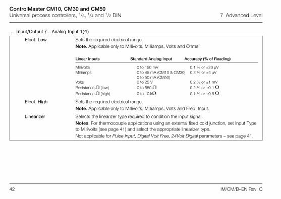
Elect. Low Sets the required electrical range.Note. Applicable only to Millivolts, Milliamps, Volts and Ohms.
Linear Inputs Standard Analog Input Accuracy (% of Reading)
Millivolts 0 to 150 mV 0.1 % or ±20 µVMilliamps 0 to 45 mA (CM10 & CM30) 0.2 % or ±4 µV
0 to 50 mA (CM50)Volts 0 to 25 V 0.2 % or ±1 mVResistance (low) 0 to 550 0.2 % or ±0.1 Resistance (high) 0 to 10 k 0.1 % or ±0.5
Elect. High Sets the required electrical range.Note. Applicable only to Millivolts, Milliamps, Volts and Freq. Input.
Linearizer Selects the linearizer type required to condition the input signal.Notes. For thermocouple applications using an external fixed cold junction, set Input Type to Millivolts (see page 41) and select the appropriate linearizer type.Not applicable for Pulse Input, Digital Volt Free, 24Volt Digital parameters – see page 41.
ControlMaster CM10, CM30 and CM50Universal process controllers, 1/8, 1/4 and 1/2 DIN 7 Advanced Level
IM/CM/B–EN Rev. Q 43
… Input/Output / …Analog Input 1(4)
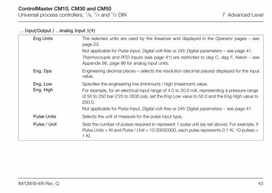
Eng Units The selected units are used by the linearizer and displayed in the Operator pages – seepage 23.Not applicable for Pulse Input, Digital volt-free or 24V Digital parameters – see page 41.Thermocouple and RTD inputs (see page 41) are restricted to deg C, deg F, Kelvin – seeAppendix 86, page 86 for analog input units.
Eng. Dps Engineering decimal places – selects the resolution (decimal places) displayed for the inputvalue.
Eng. LowEng. High
Specifies the engineering low (minimum) / high (maximum) value. For example, for an electrical input range of 4.0 to 20.0 mA, representing a pressure range of 50 to 250 bar (725 to 2630 psi), set the Eng Low value to 50.0 and the Eng High value to 250.0.Not applicable for Pulse Input, Digital volt-free or 24V Digital parameters – see page 41.
Pulse Units Selects the unit of measure for the pulse input type.
Pulse / Unit Sets the number of pulses required to represent 1 pulse unit (as set above). For example, if Pulse Units = Kl and Pulse / Unit = 10.00000000, each pulse represents 0.1 Kl, 10 pulses = 1 Kl.

ControlMaster CM10, CM30 and CM50Universal process controllers, 1/8, 1/4 and 1/2 DIN 7 Advanced Level
44 IM/CM/B–EN Rev. Q
… Input/Output / …Analog Input 1(4)
Broken Sensor If an input failure occurs, the input value can be configured to drive in a set direction.
None No action taken.
Automatic If the value of failed input is below Eng Low (see page 43), the input value is driven tominimum downscale value; otherwise it is driven to the maximum upscale value.
Upscale The input is driven to the maximum upscale value.
Downscale The input is driven to the minimum downscale value.
Filter Time The input is averaged over the time set.
Fault Detect Sets a tolerance level (as a % of the engineering range) to allow for deviation of the inputsignal above or below the engineering range before an input failure is detected.
Zero AdjustmentSpan Adjustment
The Zero Adjustment and Span Adjustment parameters enable fine tuning of the inputs toeliminate system errors. Apply a known input value and adjust until the required input valueis displayed. Normally, Zero Adjustment is used with input values close to Eng Low (adjustment isperformed by applying an offset to the reading). and Span Adjustment is used with valuesclose to Eng High (adjustment is performed by applying a multiplier to the reading).

ControlMaster CM10, CM30 and CM50Universal process controllers, 1/8, 1/4 and 1/2 DIN 7 Advanced Level
IM/CM/B–EN Rev. Q 45
…Input/Output
Analog Outputs The analog outputs can be configured to retransmit any analog value and have aconfigurable range from 0 to 24 mA. Output 1 can also be configured to function as a digitaloutput.
Analog Output 1(2) Note. Analog Output 2 is available only if an option board is fitted – see pages 16 (CM10), 17 (CM30 and 17 (CM50).
Output Type Selects the analog or digital output type required (applicable to Analog Output 1 only).
Source Selects the parameter to be assigned to the output – see Appendix A, page 82 fordescription of sources.
Elect. Low* The current output required when the source value is equal to the Eng Low value – see page 43.
Elect. High* The current output required when the source value is equal to the Eng High value – see page 43.
*Not applicable if Output Type is Digital or Source is None.
ControlMaster CM10, CM30 and CM50Universal process controllers, 1/8, 1/4 and 1/2 DIN 7 Advanced Level
46 IM/CM/B–EN Rev. Q
…Input/Output / …Analog Outputs / …Analog Output 1 (2)
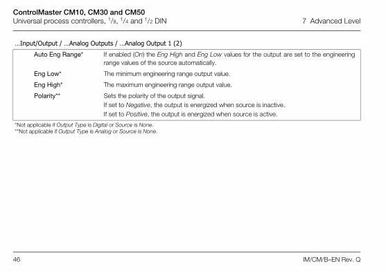
Auto Eng Range* If enabled (On) the Eng High and Eng Low values for the output are set to the engineeringrange values of the source automatically.
Eng Low* The minimum engineering range output value.
Eng High* The maximum engineering range output value.
Polarity** Sets the polarity of the output signal. If set to Negative, the output is energized when source is inactive. If set to Positive, the output is energized when source is active.
*Not applicable if Output Type is Digital or Source is None.**Not applicable if Output Type is Analog or Source is None.
ControlMaster CM10, CM30 and CM50Universal process controllers, 1/8, 1/4 and 1/2 DIN 7 Advanced Level
IM/CM/B–EN Rev. Q 47
…Input/Output
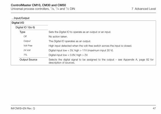
Digital I/O
Digital IO 1(to 6)
Type Sets the Digital IO to operate as an output or an input.
Off No action taken.
Output The Digital IO operates as an output.
Volt Free High input detected when the volt-free switch across the input is closed.
24 Volt Digital input low < 5V, high > 11V (maximum input 30 V).
TTL Digital input low < 0.8V, high > 2V.
Output Source Selects the digital signal to be assigned to the output – see Appendix A, page 82 fordescription of sources.

ControlMaster CM10, CM30 and CM50Universal process controllers, 1/8, 1/4 and 1/2 DIN 7 Advanced Level
48 IM/CM/B–EN Rev. Q
…Input/Output / …Digital I/O / …Digital IO 1(to 6)
Polarity Sets the polarity of the output signal.
Positive For an output, the output is high if the source is active.For an input, the input is active if a high signal is detected.
Negative For an output the output is high if the source is inactive.For an input, the input is active if a low signal is detected.
Relays
Relay 1 (to 4)
Source Selects the digital signal to be assigned to the relay – see Appendix A, page 82 fordescription of sources.
Polarity Sets the polarity of the relay.
Positive The relay is energized If the source is active.
Negative The relay is energized If the source is inactive.

ControlMaster CM10, CM30 and CM50Universal process controllers, 1/8, 1/4 and 1/2 DIN 7 Advanced Level
IM/CM/B–EN Rev. Q 49
7.4 Control
Enables the setpoints, control functions and outputs to be configured.
Loop 1 Setpoints
The controller can configure independent local setpoint values, remote setpoint functionality and limit theabsolute values and rate of change of the control setpoint.
Low LimitHigh Limit
The setpoint Low / High Limit parameters define the maximum and minimum values for the local and / orremote setpoints. Setpoint limits do not apply in Manual control mode with local setpoint tracking enabled.If the setpoint is out of limits when Auto control mode is selected, the setpoint value can only be adjustedtowards its limits.
No. of Local SP’s
Selects the number of independent local (internal) setpoints required. Local setpoints can be selected from the Operator level menu or via a digital signal.
Local Setpoint 1(2)
If the value is adjusted in the Operator level (see page 23), its value here is also updated.
MenuControl
ControlMaster CM10, CM30 and CM50Universal process controllers, 1/8, 1/4 and 1/2 DIN 7 Advanced Level
50 IM/CM/B–EN Rev. Q
…Control / …Loop 1 Setpoints
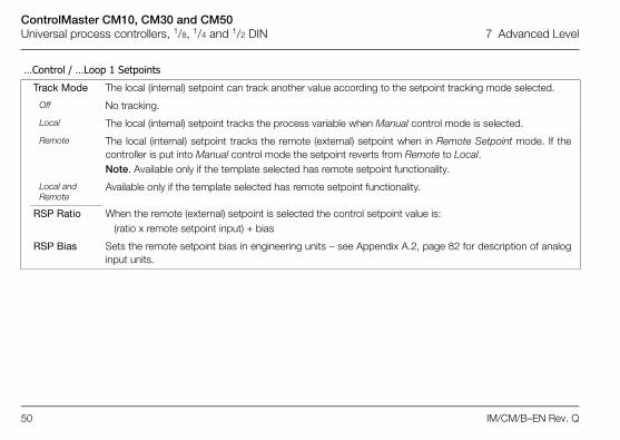
Track Mode The local (internal) setpoint can track another value according to the setpoint tracking mode selected.
Off No tracking.
Local The local (internal) setpoint tracks the process variable when Manual control mode is selected.
Remote The local (internal) setpoint tracks the remote (external) setpoint when in Remote Setpoint mode. If thecontroller is put into Manual control mode the setpoint reverts from Remote to Local.Note. Available only if the template selected has remote setpoint functionality.
Local and Remote
Available only if the template selected has remote setpoint functionality.
RSP Ratio When the remote (external) setpoint is selected the control setpoint value is:(ratio x remote setpoint input) + bias
RSP Bias Sets the remote setpoint bias in engineering units – see Appendix A.2, page 82 for description of analoginput units.

ControlMaster CM10, CM30 and CM50Universal process controllers, 1/8, 1/4 and 1/2 DIN 7 Advanced Level
IM/CM/B–EN Rev. Q 51
…Control / …Loop 1 Setpoints
RSP Fault Action
The action required when a fault occurs with the remote setpoint.
No Action No fault action.
Local Selects the local (internal) setpoint mode.
Local Default Selects the local (internal) setpoint mode and sets its value to the default setpoint.
Default Setpoint
Sets the value required for the local (internal) setpoint under remote setpoint fault conditions.
Ramp Mode See Basic Level, page 28.
Ramp Rate See Basic Level, page 28.
Select Sources
Selection of local setpoints and changing the setpoint mode (between local [internal] and remote[external]) can be controlled by digital signals, either from internal digital signals (for example, alarm states)or from external signals via digital inputs (or digital communications) – see Appendix A, page 82 fordescription of sources.
LSP 1/2 Toggle
The (level-triggered) source required to select either local setpoint 1(LSP1) or local setpoint 2 (LSP2). A low signal locks the local setpoint asLSP1; a high signal locks it as LSP2. LSP1 LSP1
LSP2
ControlMaster CM10, CM30 and CM50Universal process controllers, 1/8, 1/4 and 1/2 DIN 7 Advanced Level
52 IM/CM/B–EN Rev. Q
…Control / …Loop 1 Setpoints / Select Sources
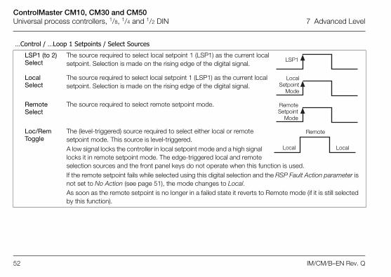
LSP1 (to 2) Select
The source required to select local setpoint 1 (LSP1) as the current localsetpoint. Selection is made on the rising edge of the digital signal.
Local Select
The source required to select local setpoint 1 (LSP1) as the current local setpoint. Selection is made on the rising edge of the digital signal.
Remote Select
The source required to select remote setpoint mode.
Loc/Rem Toggle
The (level-triggered) source required to select either local or remote setpoint mode. This source is level-triggered. A low signal locks the controller in local setpoint mode and a high signal locks it in remote setpoint mode. The edge-triggered local and remote selection sources and the front panel keys do not operate when this function is used. If the remote setpoint fails while selected using this digital selection and the RSP Fault Action parameter is not set to No Action (see page 51), the mode changes to Local. As soon as the remote setpoint is no longer in a failed state it reverts to Remote mode (if it is still selected by this function).
LSP1
LocalSetpoint
Mode
RemoteSetpoint
Mode
Local Local
Remote
ControlMaster CM10, CM30 and CM50Universal process controllers, 1/8, 1/4 and 1/2 DIN 7 Advanced Level
IM/CM/B–EN Rev. Q 53
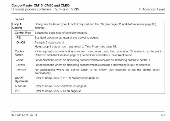
…Control
Loop 1 Control
Configures the basic type of control required and the PID (see page 32) and Autotune (see page 30) settings.
Control Type Selects the basic type of controller required.
PID Standard proportional, integral and derivative control.
On/Off A simple 2-state control.Note. Loop 1 output type must be set to Time Prop – see page 35.
Control Action
If the required controller action is known it can be set using this parameter. Otherwise it can be set toUnknown and Autotune (see page 30) determines and selects the correct action.
Direct For applications where an increasing process variable requires an increasing output to control it.
Reverse For applications where an increasing process variable requires a decreasing output to control it.
Unknown For applications where the control action is not known (run Autotune to set the control actionautomatically).
On/Off Hysteresis
Refer to Basic Level / On / Off Hysteresis on page 29.
Autotune Refer to Basic Level / Autotune on page 30.
PID Refer to Basic Level / PID on page 32.
ControlMaster CM10, CM30 and CM50Universal process controllers, 1/8, 1/4 and 1/2 DIN 7 Advanced Level
54 IM/CM/B–EN Rev. Q
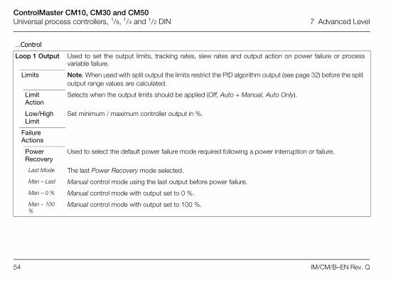
…Control
Loop 1 Output Used to set the output limits, tracking rates, slew rates and output action on power failure or processvariable failure.
Limits Note. When used with split output the limits restrict the PID algorithm output (see page 32) before the split output range values are calculated.
Limit Action
Selects when the output limits should be applied (Off, Auto + Manual, Auto Only).
Low/High Limit
Set minimum / maximum controller output in %.
Failure Actions
Power Recovery
Used to select the default power failure mode required following a power interruption or failure.
Last Mode The last Power Recovery mode selected.
Man – Last Manual control mode using the last output before power failure.
Man – 0 % Manual control mode with output set to 0 %.
Man – 100 %
Manual control mode with output set to 100 %.
ControlMaster CM10, CM30 and CM50Universal process controllers, 1/8, 1/4 and 1/2 DIN 7 Advanced Level
IM/CM/B–EN Rev. Q 55
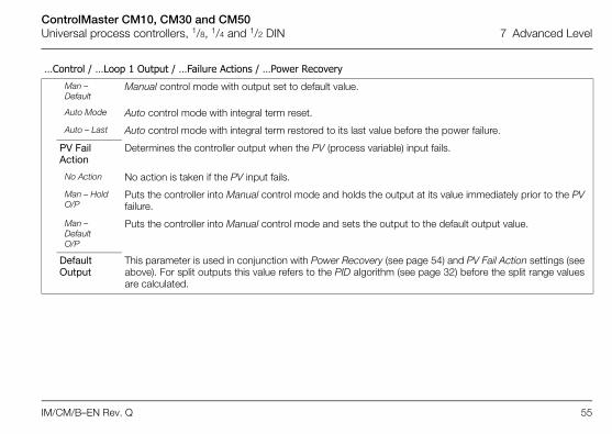
…Control / …Loop 1 Output / …Failure Actions / …Power Recovery
Man – Default
Manual control mode with output set to default value.
Auto Mode Auto control mode with integral term reset.
Auto – Last Auto control mode with integral term restored to its last value before the power failure.
PV Fail Action
Determines the controller output when the PV (process variable) input fails.
No Action No action is taken if the PV input fails.
Man – Hold O/P
Puts the controller into Manual control mode and holds the output at its value immediately prior to the PVfailure.
Man – Default O/P
Puts the controller into Manual control mode and sets the output to the default output value.
Default Output
This parameter is used in conjunction with Power Recovery (see page 54) and PV Fail Action settings (seeabove). For split outputs this value refers to the PID algorithm (see page 32) before the split range valuesare calculated.
ControlMaster CM10, CM30 and CM50Universal process controllers, 1/8, 1/4 and 1/2 DIN 7 Advanced Level
56 IM/CM/B–EN Rev. Q
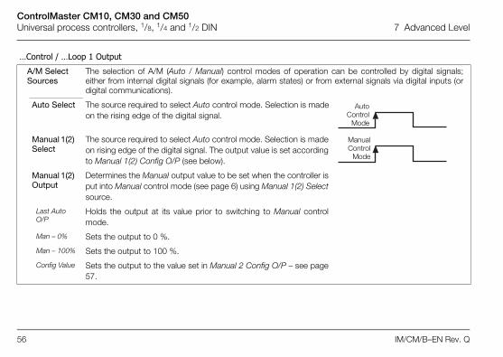
…Control / …Loop 1 Output
A/M Select Sources
The selection of A/M (Auto / Manual) control modes of operation can be controlled by digital signals;either from internal digital signals (for example, alarm states) or from external signals via digital inputs (ordigital communications).
Auto Select The source required to select Auto control mode. Selection is madeon the rising edge of the digital signal.
Manual 1(2) Select
The source required to select Auto control mode. Selection is madeon rising edge of the digital signal. The output value is set accordingto Manual 1(2) Config O/P (see below).
Manual 1(2) Output
Determines the Manual output value to be set when the controller isput into Manual control mode (see page 6) using Manual 1(2) Selectsource.
Last Auto O/P
Holds the output at its value prior to switching to Manual controlmode.
Man – 0% Sets the output to 0 %.
Man – 100% Sets the output to 100 %.
Config Value Sets the output to the value set in Manual 2 Config O/P – see page57.
AutoControl
Mode
ManualControl
Mode
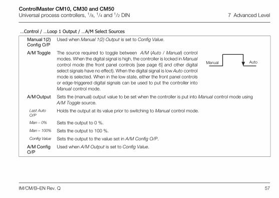
ControlMaster CM10, CM30 and CM50Universal process controllers, 1/8, 1/4 and 1/2 DIN 7 Advanced Level
IM/CM/B–EN Rev. Q 57
…Control / …Loop 1 Output / …A/M Select Sources
Manual 1(2) Config O/P
Used when Manual 1(2) Output is set to Config Value.
A/M Toggle The source required to toggle between A/M (Auto / Manual) controlmodes. When the digital signal is high, the controller is locked in Manualcontrol mode (the front panel controls [see page 6] and other digitalselect signals have no effect). When the digital signal is low Auto controlmode is selected. When in the low state, either the front panel controlsor edge-triggered digital signals can be used to put the controller intoManual control mode.
A/M Output Sets the (manual) output value to be set when the controller is put into Manual control mode using A/M Toggle source.
Last Auto O/P
Holds the output at its value prior to switching to Manual control mode.
Man – 0% Sets the output to 0 %.
Man – 100% Sets the output to 100 %.
Config Value Sets the output to the value set in A/M Config O/P.
A/M Config O/P
Used when A/M Output is set to Config Value.
Manual Auto
ControlMaster CM10, CM30 and CM50Universal process controllers, 1/8, 1/4 and 1/2 DIN 7 Advanced Level
58 IM/CM/B–EN Rev. Q
…Control / …Loop 1 Output
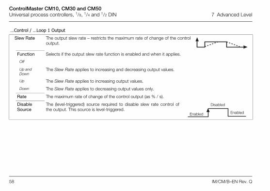
Slew Rate The output slew rate – restricts the maximum rate of change of the controloutput.
Function Selects if the output slew rate function is enabled and when it applies.
Off
Up and Down
The Slew Rate applies to increasing and decreasing output values.
Up The Slew Rate applies to increasing output values.
Down The Slew Rate applies to decreasing output values only.
Rate The maximum rate of change of the control output (as % / s).
Disable Source
The (level-triggered) source required to disable slew rate control ofthe output. This source is level-triggered.
Enabled
Disabled
Enabled

ControlMaster CM10, CM30 and CM50Universal process controllers, 1/8, 1/4 and 1/2 DIN 7 Advanced Level
IM/CM/B–EN Rev. Q 59
…Control / …Loop 1 Output
Tracking Enables the control output to be configured to follow a tracking signal when in Auto control mode. When in Manual control mode, the output can be adjusted by the user as normal. If the slew rate function is enabled, the switching from Manual to Auto is bumpless. If the value set by the tracking signal is different to that set manually, the output ramps to its expected auto value at the speed set in the slew rate. If the Signal Source is set to None, tracking is disabled and the normal PID output (see page 32) is provided as the control output.
SourceSignal Source
Sets the source of the signal required to be tracked by the output in Auto control mode. If set to None, output tracking is disabled.
Mode Selects if the output slew rate function is enabled and when it applies.
In Auto Control output = tracking signal when in Auto control mode
Auto + OP Control output = tracking signal + change in PID output, when in Auto control mode.
When Enabled
When enable source is active, control output = tracking signal when in Auto control mode.
When Enabled + OP
When enable source is active, control output = tracking signal + change in PID output, when in Auto control mode.
Enable Source
Sets the digital signal to enable output tracking.Note. Applicable only if Mode = When Enabled or When Enabled + OP.
ControlMaster CM10, CM30 and CM50Universal process controllers, 1/8, 1/4 and 1/2 DIN 7 Advanced Level
60 IM/CM/B–EN Rev. Q
…Control
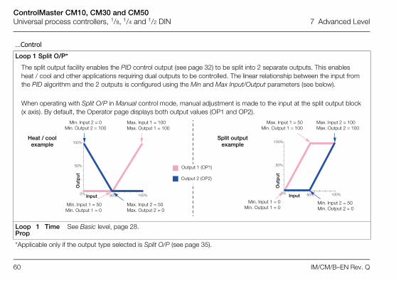
Loop 1 Split O/P*
The split output facility enables the PID control output (see page 32) to be split into 2 separate outputs. This enables heat / cool and other applications requiring dual outputs to be controlled. The linear relationship between the input from the PID algorithm and the 2 outputs is configured using the Min and Max Input/Output parameters (see below).
When operating with Split O/P in Manual control mode, manual adjustment is made to the input at the split output block (x axis). By default, the Operator page displays both output values (OP1 and OP2).
Loop 1 TimeProp
See Basic level, page 28.
*Applicable only if the output type selected is Split O/P (see page 35).
50%
50%
100%
100%0%
50%
50%
100%
100%0%
Output 1 (OP1)
Output 2 (OP2)
Max. Input 2 = 50Max. Output 2 = 0
Min. Input 2 = 0Min. Output 2 = 100
Max. Input 1 = 50Min. Output 1 = 100
Max. Input 2 = 100Max. Output 2 = 100
Min. Input 2 = 50Min. Output 2 = 0
Min. Input 1 = 50Min. Output 1 = 0
Split output example
Min. Input 1 = 0Min. Output 1 = 0
Max. Input 1 = 100Max. Output 1 = 100
Input Input
Out
put
Out
put
Heat / cool example
ControlMaster CM10, CM30 and CM50Universal process controllers, 1/8, 1/4 and 1/2 DIN 7 Advanced Level
IM/CM/B–EN Rev. Q 61
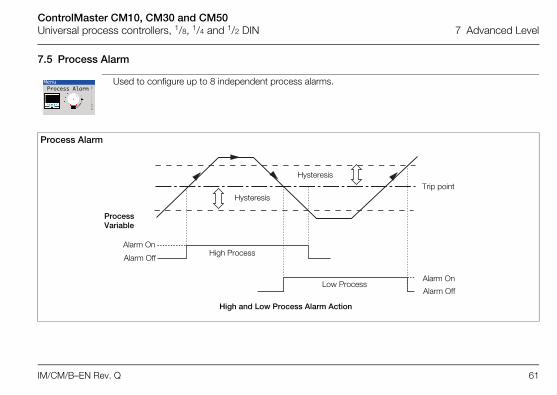
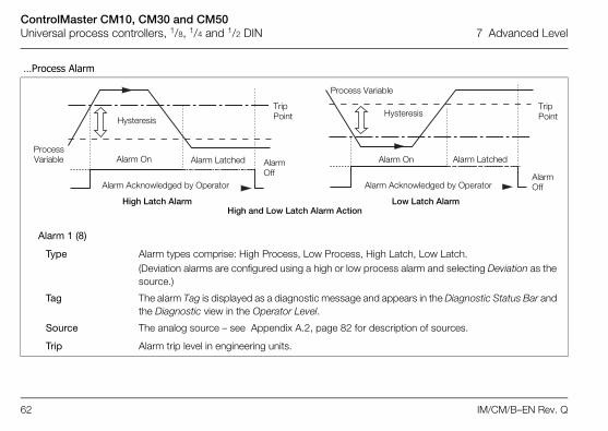
7.5 Process Alarm
Used to configure up to 8 independent process alarms.
Process Alarm
MenuProcess Alarm
High and Low Process Alarm Action
Trip point
Process Variable
Alarm On
Alarm Off
Alarm On
Alarm Off
High Process
Low Process
Hysteresis
Hysteresis
ControlMaster CM10, CM30 and CM50Universal process controllers, 1/8, 1/4 and 1/2 DIN 7 Advanced Level
62 IM/CM/B–EN Rev. Q
…Process Alarm
Alarm 1 (8)
Type Alarm types comprise: High Process, Low Process, High Latch, Low Latch.(Deviation alarms are configured using a high or low process alarm and selecting Deviation as the source.)
Tag The alarm Tag is displayed as a diagnostic message and appears in the Diagnostic Status Bar and the Diagnostic view in the Operator Level.
Source The analog source – see Appendix A.2, page 82 for description of sources.
Trip Alarm trip level in engineering units.
High and Low Latch Alarm Action
Trip Point
Alarm On
Alarm Off
Hysteresis
Process Variable Alarm Latched
Alarm Acknowledged by Operator Alarm Acknowledged by Operator
Alarm Off
Trip Point
Alarm On
Hysteresis
Alarm Latched
Process Variable
High Latch Alarm Low Latch Alarm
ControlMaster CM10, CM30 and CM50Universal process controllers, 1/8, 1/4 and 1/2 DIN 7 Advanced Level
IM/CM/B–EN Rev. Q 63
7.6 Communication
…Process Alarm / … Alarm 1 (to 8)
Hysteresis Hysteresis trip level in engineering units. Activated at the alarm trip level but deactivated onlywhen the process variable has moved into the safe region by an amount equal to the hysteresisvalue – see Process Alarm examples on page 61.
Time Hysteresis If an alarm trip value is exceeded, the alarm does not become active until the Time Hysteresis valuehas expired. If the signal goes out of the alarm condition before the Time Hysteresis has expired,the hysteresis timer is reset.
Display Enable Enables an alarm to be used for control purposes without it appearing as an active alarm state inthe Operator Level or Diagnostic view – see page 23.
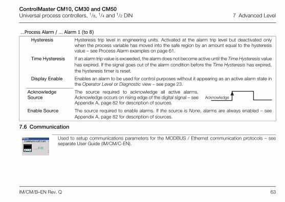
Acknowledge Source
The source required to acknowledge all active alarms.Acknowledge occurs on rising edge of the digital signal – seeAppendix A, page 82 for description of sources.
Enable Source The source required to enable alarms. If the source is None, alarms are always enabled – seeAppendix A, page 82 for description of sources.
Acknowledge
Used to setup communications parameters for the MODBUS / Ethernet communication protocols – seeseparate User Guide (IM/CM/C-EN).
MenuCommunication
ControlMaster CM10, CM30 and CM50Universal process controllers, 1/8, 1/4 and 1/2 DIN 7 Advanced Level
64 IM/CM/B–EN Rev. Q
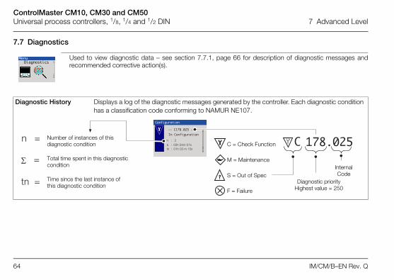
7.7 Diagnostics
Used to view diagnostic data – see section 7.7.1, page 66 for description of diagnostic messages andrecommended corrective action(s).
Diagnostic History Displays a log of the diagnostic messages generated by the controller. Each diagnostic condition has a classification code conforming to NAMUR NE107.
MenuDiagnostics
��������
��� ��������� �
�����������������������
������������ ������
� ��������� �
�������������
�
�
����
����
Internal Code
Diagnostic priorityHighest value = 250
Number of instances of this diagnostic condition
Total time spent in this diagnostic condition
Time since the last instance of this diagnostic condition
C = Check Function
M = Maintenance
S = Out of Spec
F = Failure

ControlMaster CM10, CM30 and CM50Universal process controllers, 1/8, 1/4 and 1/2 DIN 7 Advanced Level
IM/CM/B–EN Rev. Q 65
…Diagnostics
Source Analysis
Analog Sources Enables the current value of any analog source to be viewed.
Analog Source Selects the analog signal to be viewed – see section A.2, page 82.
View Value Displays the value of the analog signal selected.
Digital Sources Enables the current state of any digital source to be viewed.
Digital Source Selects the digital signal to be viewed – see section A.1, page 82.
View State Displays the state of the digital signal selected.
Invalid Sources Select edit to display any invalid analog or digital sources that are used in the configuration.Reasons for invalid sources include: Hardware not fitted Software not fitted Digital I/O configured as wrong type Alarms not configured Math, logic, timer or custom linearizer not configured
ControlMaster CM10, CM30 and CM50Universal process controllers, 1/8, 1/4 and 1/2 DIN 7 Advanced Level
66 IM/CM/B–EN Rev. Q
7.7.1 Diagnostic Messages
Icon Number / Message Possible Cause Suggested Action
242.004(240.005)
ADC 1(2) Failed
Temporary or permanent failure of analog to digital converter on the main I/O board.
Cycle power to device.
If problem persists replace main I/O board. Contact local service organization.
250.000PV 1 Failed
Problem with Input assigned to Loop 1 PV. Broken sensor leads, defective input source or input signal out of permitted range.
Check wiring. Check input source.
Check if input signal is outside permitted limits.
246.002RSP 1 Failed
Problem with Input assigned to Loop 1 Remote Setpoint. Broken sensor leads, defective input source or input signal out of permitted range.
Check wiring. Check input source.
Check if input signal is outside permitted limits.
222.014(220.015)
CJ 1(2) Failed
Error in Cold junction measurement associated with AIN1. Wiring fault or defective sensor.
Check cold junction device is correctly fitted.
Ensure I/P 2(4) is turned off. Replace CJ sensor.
226.012DV 1 Failed
Problem with input assigned to Loop 1 disturbance variable. Broken sensor leads, defective input source or input signal out of permitted range.
Check wiring. Check input source.
Check if input signal is outside permitted limits.
230.010WV 1 Failed
Problem with input assigned to Loop 1 wild variable. Broken sensor leads, defective input source or input signal out of permitted range.
Check wiring. Check input source.
Check if input signal is outside permitted limits.
Table 7.1 Diagnostic Messages
ControlMaster CM10, CM30 and CM50Universal process controllers, 1/8, 1/4 and 1/2 DIN 7 Advanced Level
IM/CM/B–EN Rev. Q 67
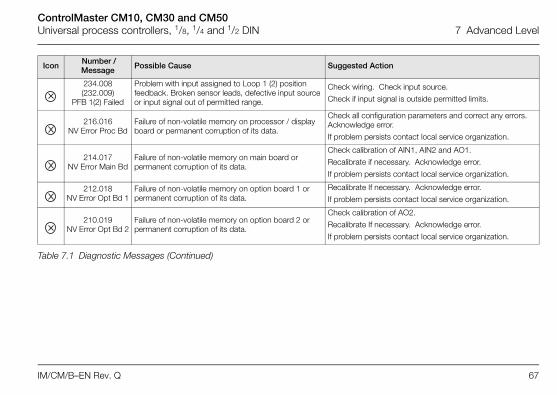
234.008(232.009)
PFB 1(2) Failed
Problem with input assigned to Loop 1 (2) position feedback. Broken sensor leads, defective input source or input signal out of permitted range.
Check wiring. Check input source.
Check if input signal is outside permitted limits.
216.016NV Error Proc Bd
Failure of non-volatile memory on processor / display board or permanent corruption of its data.
Check all configuration parameters and correct any errors. Acknowledge error.
If problem persists contact local service organization.
214.017NV Error Main Bd
Failure of non-volatile memory on main board or permanent corruption of its data.
Check calibration of AIN1, AIN2 and AO1.
Recalibrate if necessary. Acknowledge error.
If problem persists contact local service organization.
212.018NV Error Opt Bd 1
Failure of non-volatile memory on option board 1 or permanent corruption of its data.
Recalibrate If necessary. Acknowledge error.
If problem persists contact local service organization.
210.019NV Error Opt Bd 2
Failure of non-volatile memory on option board 2 or permanent corruption of its data.
Check calibration of AO2.
Recalibrate If necessary. Acknowledge error.
If problem persists contact local service organization.
Icon Number / Message Possible Cause Suggested Action
Table 7.1 Diagnostic Messages (Continued)

ControlMaster CM10, CM30 and CM50Universal process controllers, 1/8, 1/4 and 1/2 DIN 7 Advanced Level
68 IM/CM/B–EN Rev. Q
208.020NV Error
Comm Bd
Failure of non-volatile memory on communications board or permanent corruption of its data.
Acknowledge error. Check communications board is correctly identified by device.
If problem persists contact local service organization.
Config Error The configuration contains a source that is no longer present or valid.
Check invalid sources in Diagnostics menu – see section 7.7, page 64.
Check configuration, check I/O required for configuration is present and correct any illegal use of the invalid signal by changing configuration or fitting additional option cards.
054.044Tune Lp1 Fail
Autotune has failed to complete its sequence or has calculated values outside of its permitted range.
Check process response. Consider changing the Autotune dynamic setting – see page 32.
Ensure process is stable and repeat autotune. If problem persists tune the loop manually.
070.040(066.041)
Tuner 1(2) AbortAutotune has been aborted by the user.
078.038(074.039)
Adaptive 1(2) Warn
Parameters calculated by adaptive control have changed by more than the permitted amounts.
Check process for issues that may have caused a large change in its dynamics, for example, a blocked valve.
Reset adaptive control.
Perform a fresh autotune.
Icon Number / Message Possible Cause Suggested Action
Table 7.1 Diagnostic Messages (Continued)
ControlMaster CM10, CM30 and CM50Universal process controllers, 1/8, 1/4 and 1/2 DIN 7 Advanced Level
IM/CM/B–EN Rev. Q 69
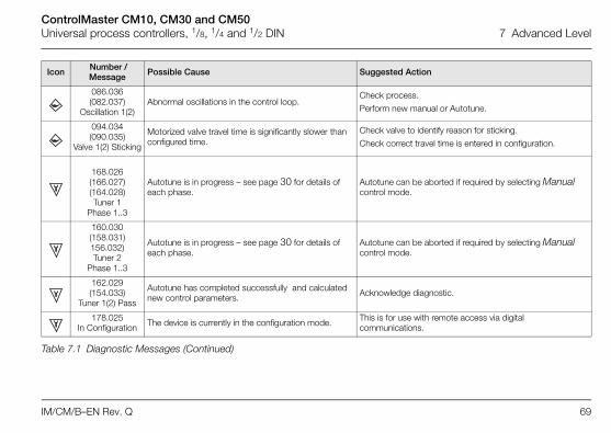
086.036(082.037)
Oscillation 1(2)Abnormal oscillations in the control loop.
Check process.
Perform new manual or Autotune.
094.034(090.035)
Valve 1(2) Sticking
Motorized valve travel time is significantly slower than configured time.
Check valve to identify reason for sticking.
Check correct travel time is entered in configuration.
168.026 (166.027)(164.028)Tuner 1
Phase 1..3
Autotune is in progress – see page 30 for details of each phase.
Autotune can be aborted if required by selecting Manual control mode.
160.030(158.031)156.032)Tuner 2
Phase 1..3
Autotune is in progress – see page 30 for details of each phase.
Autotune can be aborted if required by selecting Manual control mode.
162.029(154.033)
Tuner 1(2) Pass
Autotune has completed successfully and calculated new control parameters. Acknowledge diagnostic.
178.025In Configuration The device is currently in the configuration mode. This is for use with remote access via digital
communications.
Icon Number / Message Possible Cause Suggested Action
Table 7.1 Diagnostic Messages (Continued)
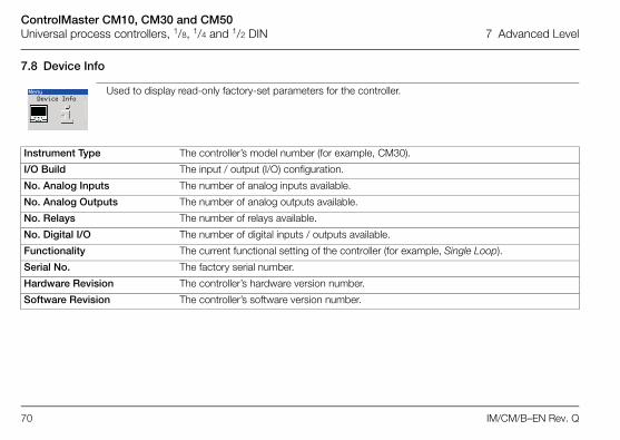
ControlMaster CM10, CM30 and CM50Universal process controllers, 1/8, 1/4 and 1/2 DIN 7 Advanced Level
70 IM/CM/B–EN Rev. Q
7.8 Device Info
Used to display read-only factory-set parameters for the controller.
Instrument Type The controller’s model number (for example, CM30).
I/O Build The input / output (I/O) configuration.
No. Analog Inputs The number of analog inputs available.
No. Analog Outputs The number of analog outputs available.
No. Relays The number of relays available.
No. Digital I/O The number of digital inputs / outputs available.
Functionality The current functional setting of the controller (for example, Single Loop).
Serial No. The factory serial number.
Hardware Revision The controller’s hardware version number.
Software Revision The controller’s software version number.
MenuDevice Info

ControlMaster CM10, CM30 and CM50Universal process controllers, 1/8, 1/4 and 1/2 DIN 8 Templates and Functionality
IM/CM/B–EN Rev. Q 71
8 Templates and Functionality
8.1 Single Loop / Single Loop with Remote SetpointThis template provides basic feedback control using three-term PID or On/Off control. The controller output is calculated fromthe difference between the process variable and the control setpoint. The control setpoint can be a fixed value entered by theuser (Local setpoint) or an input from a remote source (remote setpoint).
Notes. Output assignments can be changed in Input/Output configuration – see page 41.
A/MPV
L/R
SP
AIN 1
AIN 2 x Ratio + Bias
LSPT1
LSPT2
LSPT3
LSPT4
Local Set Point
Manual Output
Loop 1PID Control
PIDO/P OP
Time Prop Output
Split Output
AO1
RLY1
OP2
OP1
Output Type
Analog Output
1
1 Single Loop + Remote Setpoint only
RSP
RLY1
RLY2AIN 3
MotorizedValve
FB
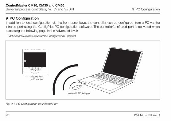
ControlMaster CM10, CM30 and CM50Universal process controllers, 1/8, 1/4 and 1/2 DIN 9 PC Configuration
72 IM/CM/B–EN Rev. Q
9 PC ConfigurationIn addition to local configuration via the front panel keys, the controller can be configured from a PC via theinfrared port using the ConfigPilot PC configuration software. The controller's infrared port is activated whenaccessing the following page in the Advanced level:
Advanced>Device Setup>IrDA Configuration>Connect
Fig. 9.1 PC Configuration via Infrared Port
Infrared Port on Controller
Infrared USB Adaptor

ControlMaster CM10, CM30 and CM50Universal process controllers, 1/8, 1/4 and 1/2 DIN 10 Specification
IM/CM/B–EN Rev. Q 73
10 Specification
OperationDisplay
Color 1/4 VGA TFT, liquid crystal display (LCD) with built-in backlight
Language
English, German, French, Italian and Spanish
Operator keypad
SecurityPassword protection
Standard functionsControl strategies
CM10 4 tactile membrane keys
CM30 and CM50 6 tactile membrane keys
Basic / Advanced User-assigned password protection (not set at factory)
Base templates
Single loop with local setpoint
Single loop with remote setpoint
Standard templates
Auto/Manual station (low signal detection)
Auto/Manual station (digital signal selection)
Analog backup station (low signal detection)
Analog backup station (digital signal detection)
Single indicator / manual loader station
Dual indicator / manual loader station
ControlMaster CM10, CM30 and CM50Universal process controllers, 1/8, 1/4 and 1/2 DIN 10 Specification
74 IM/CM/B–EN Rev. Q
Control output types
Current proportioning
Time proportioning
On / Off
Motorized valve with feedback
Motorized valve without feedback
Split output – with combinations of relay, digital output and current outputs
Control parameters
Proportional band * 0.0 to 999.9 %
Integral * 0 to 10000 s
Derivative * 0.0 to 999.9 s
Manual Reset 0.0 to 100.0 %
Setpoints
* 3 sets of PID parameters when used with Gain Scheduling facility
Autotune
On-demand calculation of control settings
Process Alarms
Acknowledgement
Via front panel keys or digital signals
Real-time alarms **
** Functionality level 'Standard' only
Local
CM10 2, selectable via digital inputs or front panel
CM30 / CM50 4, selectable via digital inputs or front panel
Remote selectable via digital input or front panel keys
Number 8
Types High / Low process High / Low latch
Source Fully configurable (for example, PV, analog input, math block inbuilt, OP control loop deviation)
Hysteresis Level and time
Alarm enable Enable / disable of individual alarms via a digital signal
Number 2
Programmable Time
Day
Duration
ControlMaster CM10, CM30 and CM50Universal process controllers, 1/8, 1/4 and 1/2 DIN 10 Specification
IM/CM/B–EN Rev. Q 75
Maths blocks *
Delay timers *
Logic equations *
Custom linearizer *
Bank control *
* Functionality level 'Standard' only
Analog inputsUniversal process inputs
Non-universal process inputs
Thermocouple types
B, E, J, K, L, N, R, S, T
Resistance thermometer
Pt100
Number 8Operators +, –, x , /
Average, Maximum, MinimumHigh / Low / Median SelectSquare rootMultiplexer
Number 2Programmable Delay
Duration
Number 8Elements 15 Per equationOperators OR, AND, NOR, NAND, NOT, EXOR
Number 2Elements 20 Breakpoints
Number of outputs 6Wear levelling Rotate or FIFO
CM10 1 Standard
CM30 / CM50 2 (1 Standard, 1 optional)
Type VoltageCurrentResistance (ohms)3-Wire RTDThermocoupleDigital volt-freeDigital 24 VFrequencyPulse
CM10 1 Standard
CM30 / CM50 2 (1 Standard, 1 optional)
Type VoltageCurrentThermocoupleDigital volt-freeDigital 24 V

ControlMaster CM10, CM30 and CM50Universal process controllers, 1/8, 1/4 and 1/2 DIN 10 Specification
76 IM/CM/B–EN Rev. Q
Other linearizations
x, x3/2, x5/2,
Digital filter
Programmable 0 to 60 s
Display range
–9999 to 99999
Update rate
125 ms
Common mode noise rejection
>120 dB at 50/60 Hz with 300 imbalance resistance
Normal (series) mode noise rejection
>60 dB at 50/60 Hz
CJC rejection ratio
0.05 °C / °C change in ambient temperature
Temperature stability
0.02 % / °C or 2 µV / °C (1 µV / °F)
Long term (input) drift
<0.1 % of reading or 10 µV annually
Input impedance
>10 M (millivolts input)
10 (mA input)
Inputs
Thermocouple Maximum Range °C (°F)
Accuracy (% of reading)
°C (°F)
B* –18 to 1800 (0 to 3270)
0.1 % or ±2 °C (3.6 °F) (above 200 °C [392 °F]) *
E –100 to 900(–140 to 1650)
0.1 % or ±0.5 °C (0.9 °F)
J –100 to 900(–140 to 1650)
0.1 % or ±0.5 °C (0.9 °F)
K –100 to 1300(–140 to 2350)
0.1 % or ±0.5 °C (0.9 °F)
L –100 to 900(–140 to 1650)
0.1 % or ±1.5 °C (2.7 °F)
N –200 to 1300(–325 to 2350)
0.1 % or ±0.5 °C (0.9 °F)
R* –18 to 1700(0 to 3000)
0.1 % or ±1 °C (1.8 °F) (above 300 °C [540 °F])
S* –18 to 1700(0 to 3000)
0.1 % or ±1 °C (1.8 °F) (above 200 °C [392 °F])
T* –250 to 300(–400 to 550)
0.1 % or ±0.5 °C (0.9 °F) (above –150 °C [–238 °F])
*For B, R, S and T thermocouples, accuracy is not guaranteed below the value stated.
ControlMaster CM10, CM30 and CM50Universal process controllers, 1/8, 1/4 and 1/2 DIN 10 Specification
IM/CM/B–EN Rev. Q 77
RTD Maximum Range °C (°F)
Accuracy (% of reading)
Pt100 –200 to 600(–325 to 1100)
0.1 % or ±0.5 °C (0.9 °F)
Linear Inputs Standard Analog Input
Accuracy(% of reading)
Millivolts
Milliamps
Volts
Resistance (low)
Resistance (high)
0 to 150 mV
0 to 45 mA (CM10 and CM30)
0 to 50 mA (CM50)
0 to 25 V
0 to 550
0 to 10 k
0.1 % or ±20 µV
0.2 % or ±4 µA
0.2 % or ±20 mV
0.2 % or ±0.1
0.5 % or ±10
Sample Interval 125 ms per sample
Digital Inputs
Type Volt-free or 24 V
Minimum pulse duration
Analog inputs 1 and 2:
Single inputs configured – 250 ms Both inputs configured as analog or digital
– 500 msAnalog inputs 3 and 4 (not CM10):
Single inputs configured – 250 ms Both inputs configured as analog or digital
– 500 ms
Consider analog inputs 1 / 2 and 3 / 4 independently
Frequency input*
Frequency range
1-signal
0-signal
0 to 6000 Hz
15 to 30 V
–3 to 5 V
*For use with devices with open collector outputs
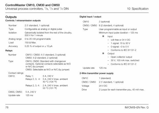
ControlMaster CM10, CM30 and CM50Universal process controllers, 1/8, 1/4 and 1/2 DIN 10 Specification
78 IM/CM/B–EN Rev. Q
OutputsControls / retransmission outputs
Relays
Digital input / output
2-Wire transmitter power supply
Number 2 (1 standard, 1 optional)
Type Configurable as analog or digital pulse
Isolation Galvanically isolated from the rest of the circuitry, 500 V for 1 minute
Analog range 0 to 20 mA programmable
Load 750 Max.
Accuracy 0.25 % of output or ± 10µA
Number CM10 / CM30: 4 (1 standard, 3 optional)CM50: 4 (2 standard, 2 optional)
Type CM10, CM30: Standard with changeover contacts. Optional contacts selectable as N/O or N/C (by jumper)CM50: Selectable as N/O or N/C (by jumper)
Contact ratingsCM10:
CM30, CM50:
Relay 1: 5 A, 240 VRelays 2, 3, 4: 5 A, 240 V (max. ambient
40 °C (104 °F)
Relays 2, 3, 4: 2 A, 240 V (max. ambient 55 °C (131 °F)
5 A, 240 V
Update rate 125 ms
CM10 2 (optional)
CM30 / CM50 6 (2 standard, 4 optional)
Type User-programmable as input or output
Minimum input pulse duration – 125 ms
Input
– volt-free or 24 V DC
– 1-signal: 15 to 30 V
– 0-signal: –3 to 5 V
– Conforms to IEC 61131-2
Output
– Open collector output
– 30 V, 100 mA max. switched
– Conforms to IEC 61131-2
Update rate 125 ms
CM10 1 (standard)
CM30 / CM50 2 (1 standard, 1 optional)
Voltage 24 V DC
Drive 2 Loops for each transmitter psu, 45 mA max.

ControlMaster CM10, CM30 and CM50Universal process controllers, 1/8, 1/4 and 1/2 DIN 10 Specification
IM/CM/B–EN Rev. Q 79
CommunicationsFor MODBUS and Ethernet communications see separate UserGuide (IM/CM/C–EN).
IrDA configuration port (standard)
EMCEmissions & immunity
Meets requirements of IEC61326 for an Industrial Environment
EnvironmentalOperating temperature range
0 to 55 °C (32 to 131 °F)*
Operating humidity range
5 to 95 %RH (non-condensing)
Storage temperature range
–20 to 70 °C (–4 to 158 °F)
*Restrictions may apply, refer to relay specification
Enclosure sealing
Vibration
Conforms to EN60068-2-6
SafetyApprovals and certifications
EN61010-1
cULus
General safety
Pollution category 2
Insulation category 2
Isolation (to inputs)
Key
= Isolation
Baud rate up to 115 kBaud
Distance up to 1 m (3 ft.)
Functions firmware upgradeconfiguration upload / download
Front face IP66 / NEMA 4X
Rest of enclosure IP20
Analog I/Ps
Tx PSU
Analog O/P 1
Analog O/P 2
CPU
Comms
Relays
Digital I/O
Mains Supply
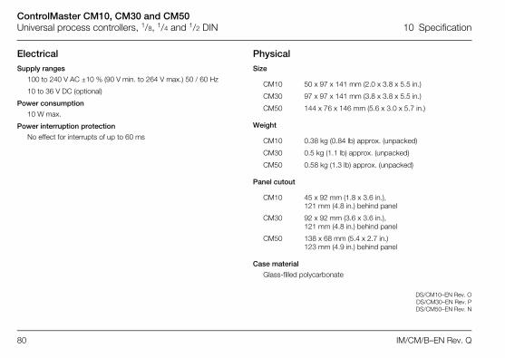
ControlMaster CM10, CM30 and CM50Universal process controllers, 1/8, 1/4 and 1/2 DIN 10 Specification
80 IM/CM/B–EN Rev. Q
ElectricalSupply ranges
100 to 240 V AC ±10 % (90 V min. to 264 V max.) 50 / 60 Hz
10 to 36 V DC (optional)
Power consumption
10 W max.
Power interruption protection
No effect for interrupts of up to 60 ms
PhysicalSize
Weight
Panel cutout
Case material
Glass-filled polycarbonate
DS/CM10–EN Rev. ODS/CM30–EN Rev. PDS/CM50–EN Rev. N
CM10 50 x 97 x 141 mm (2.0 x 3.8 x 5.5 in.)
CM30 97 x 97 x 141 mm (3.8 x 3.8 x 5.5 in.)
CM50 144 x 76 x 146 mm (5.6 x 3.0 x 5.7 in.)
CM10 0.38 kg (0.84 lb) approx. (unpacked)
CM30 0.5 kg (1.1 lb) approx. (unpacked)
CM50 0.58 kg (1.3 lb) approx. (unpacked)
CM10 45 x 92 mm (1.8 x 3.6 in.), 121 mm (4.8 in.) behind panel
CM30 92 x 92 mm (3.6 x 3.6 in.), 121 mm (4.8 in.) behind panel
CM50 138 x 68 mm (5.4 x 2.7 in.) 123 mm (4.9 in.) behind panel

ControlMaster CM10, CM30 and CM50Universal process controllers, 1/8, 1/4 and 1/2 DIN Notes
IM/CM/B–EN Rev. Q 81
Notes

ControlMaster CM10, CM30 and CM50Universal process controllers, 1/8, 1/4 and 1/2 DIN Appendix A – Digital and Analog Sources
82 IM/CM/B–EN Rev. Q
Appendix A – Digital and Analog Sources
A.1 Digital Sources
A.2 Analog Sources
Note. Numbers in brackets indicate additional parameters, for example, 'Alarm 1(8) Ack. State indicates that 8 Alarm Ack. State parameters are available.
Source Name Description [Comment]
Alarm 1(8) Ack. State Acknowledged alarm = 0Unacknowledged alarm = 1
Alarm 1(8) State Alarm state
Anlg IP 1(4) FailActive input failure (when the signal detectedat the analog input is outside the fault detectlevel specified during configuration)
AO1(2) Loop Break Analog outputIP 1(4) Digital State Input 1(4) digital state
Loop 1 SP Mode Setpoint mode selected 0 = Local, 1 = Remote
Loop 1 Auto Mode Automatic control mode1 = Setpoint selected
Loop 1 LSP 1(4) State Local setpoint state
Loop 1 Manual Mode Manual control mode 1 = Manual
Loop 1 TP OP1 Time proportioning output
Softkey Toggle Front panel soft key toggles the source’sstate
Softkey Edge Front panel soft key sets the source active on key press
Source Name Description
Anlg IP 1 (4) Analog input
Loop 1 Control OP Control output value
Loop 1 Deviation Loop 1 deviation
Loop 1 LSP Local setpoint loop
Loop 1 PV Loop 1(2) process variable
Loop 1 SP Loop control setpoint
Loop 1 Split OP1 Loop 1 split output
Source Name Description [Comment]

ControlMaster CM10, CM30 and CM50Universal process controllers, 1/8, 1/4 and 1/2 DIN Appendix B – Configuration Error Codes
IM/CM/B–EN Rev. Q 83
Appendix B – Configuration Error CodesConfiguration errors are generated when a signal assigned as a source for something has failed. Configuration errors aredisplayed as numerical codes and a description of each code is shown in the following tables:
Error Code Error Description
1 Analog Input Value A1 (I/P 1)2 Analog Input Value A2 (I/P 2)
3 Analog Input Value B1 (I/P 3 – CM50)
4 Analog Input Value B2 (I/P 4 – CM50)
5 Analog Input Value C1(I/P 3 – CM30)
6 Analog Input Value C2(I/P 4 – CM30)
9 Setpoint Selected LSPT Value 110 Setpoint Contrl SP Value 111 Setpoint Selected Ratio Value 112 Setpoint Selected Bias Value 113 Setpoint Actual Ratio Value 114 Setpoint Selected LSPT Value 215 Setpoint Contrl SP Value 2
16 Setpoint Selected Ratio Value 217 Setpoint Selected Bias Value 218 Setpoint Actual Ratio Value 242 Control Output Value 143 Control Output Value 244 Dual Output Loop 1 Value 145 Dual Output Loop 1 Value 246 Dual Output Loop 2 Value 147 Dual Output Loop 2 Value 248 Mot Valve Output 149 Mot Valve Output 250 PV Maximum Value 151 PV Minimum Value 152 PV Average Value 153 Volume Value 154 PV Maximum Value 2
Error Code Error Description
55 PV Minimum Value 256 PV Average Value 257 Volume Value 258 Customer Linearizer Value 159 Customer Linearizer Value 260 Profile User Value 161 Profile User Value 262 Mot Valve Position 163 Mot Valve Position 264 template Block PV Value 165 Template Block PV Value 266 Template Block Deviation Value 167 Template Block Deviation Value 2
68 Template Block Feedforward Value 1
69 Template Block Feedforward Value 2
Error Code Error Description
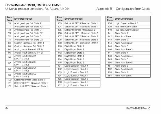
ControlMaster CM10, CM30 and CM50Universal process controllers, 1/8, 1/4 and 1/2 DIN Appendix B – Configuration Error Codes
84 IM/CM/B–EN Rev. Q
70 Analogue Input Fail State A171 Analogue Input Fail State A272 Analogue Input Fail State B173 Analogue Input Fail State B274 Analogue Input Fail State C175 Analogue Input Fail State C284 Custom Linearizer Fail State 185 Custom Linearizer Fail State 294 Analog Input State A1 (I/P 1)95 Analog Input State A2 (I/P 2)
96 Analog Input State B1 (I/P 3 – CM50)
97 Analog Input State B2(I/P 4 – CM50)
98 Analog Input State C1(I/P 3 – CM30)
99 Analog Input State C2(I/P 4 – CM30)
100 Setpoint Remote Mode State 1101 Setpoint LSPT 1 Selected State 1102 Setpoint LSPT 2 Selected State 1
Error Code Error Description
103 Setpoint LSPT 3 Selected State 1104 Setpoint LSPT 4 Selected State 1105 Setpoint Remote Mode State 2106 Setpoint LSPT 1 Selected State 2107 Setpoint LSPT 2 Selected State 2108 Setpoint LSPT 3 Selected State 2109 Setpoint LSPT 4 Selected State 2110 Digital Input State 1111 Digital Input State 2112 Digital Input State 3113 Digital Input State 4114 Digital Input State 5115 Digital Input State 6131 Logic Equation Result 1132 Logic Equation Result 2133 Logic Equation Result 3134 Logic Equation Result 4135 Logic Equation Result 5136 Logic Equation Result 6137 Logic Equation Result 7
Error Code Error Description
138 Logic Equation Result 8139 Real Time Alarm State 1140 Real Time Alarm State 2141 Alarm State 1142 Alarm Ack State 1143 Alarm State 2144 Alarm Ack State 2145 Alarm State 3146 Alarm Ack State 3147 Alarm State 4148 Alarm Ack State 4149 Alarm State 5150 Alarm Ack State 5151 Alarm State 6152 Alarm Ack State 6153 Alarm State 7154 Alarm Ack State 7
Error Code Error Description
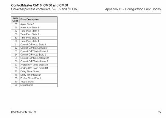
ControlMaster CM10, CM30 and CM50Universal process controllers, 1/8, 1/4 and 1/2 DIN Appendix B – Configuration Error Codes
IM/CM/B–EN Rev. Q 85
155 Alarm State 8156 Alarm Ack State 8157 Time Prop State 1158 Time Prop State 2159 Time Prop State 3160 Time Prop State 4161 Control O/P Auto State 1162 Control O/P Manual State 1163 Control O/P Track Status 1164 Control O/P Auto State 2165 Control O/P Manual State 2166 Control O/P Track Status 2167 Analog O/P Loop break A1168 Analog O/P Loop break B1177 Delay Timer State 1178 Delay Timer State 2188 Profiler Timed Event189 Toggle Signal190 Edge Signal
Error Code Error Description
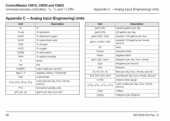
ControlMaster CM10, CM30 and CM50Universal process controllers, 1/8, 1/4 and 1/2 DIN Appendix C – Analog Input (Engineering) Units
86 IM/CM/B–EN Rev. Q
Appendix C – Analog Input (Engineering) UnitsUnit Description
% %
% sat % saturation
%dO2 % dissolved oxygen
%HCI % hydrochloric acid
%N2 % nitrogen
%O2 % oxygen
%OBS % obscuration
%RH % relative humidity
A amps
bar bar
CUMEC cubic metre per second
deg C / F degrees Celsius / Fahrenheit
Feet imperial feet
ft3/d, ft3/h, ft3/m, ft3/s cubic feet per day, hour, minute, second.
FTU formazine turbidity units
g/d, g/h, g/l grams per day, hour, liter
gal/d (UK) imperial gallons per day
gal/d (US) US gallons per day
gal/h (UK) / (US) imperial / US gallons per hour
gal/m, s (UK) / (US) imperial / US gallons per minute, second.
Hz hertz
Inches imperial inches
Kelvin degrees Kelvin
kg/d, kg/h, kg/m kilograms per day, hour, minute.
kg/s kilograms per second
kHz kilohertz
l/d, l/h, l/m, l/s liters per day, hour, minute, second.
lb/d, lb/h, lb/m, lb/s pounds per day, hour, minute, second.
m WG meters water gauge
m3/d, m3/h, m3/m, m3/s cubic meters per day, hour, minute, second.
mbar millibar
mg/kg milligrams per kilogram
Unit Description
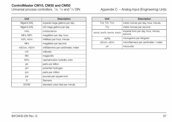
ControlMaster CM10, CM30 and CM50Universal process controllers, 1/8, 1/4 and 1/2 DIN Appendix C – Analog Input (Engineering) Units
IM/CM/B–EN Rev. Q 87
Mgal/d (UK) imperial mega gallons per day
Mgal/d (US) US mega gallons per day
mho conductance
Ml/d, Ml/h megaliters per day, hour.
ml/h, ml/m milliliters per hour, minute.
Ml/s megaliters per second
mS/cm, mS/m milliSiemens per centimeter, meter
mV millivolts
MV megavolts
NTU nephelometric turbidity units
pb parts per billion
pH potential Hydrogen
pm parts per million
psi pounds per square inch
S Siemens
SCFM standard cubic feet per minute
Unit Description
T/d, T/h, T/m metric tonnes per day, hour, minute.
T/s metric tonnes per second
ton/d, ton/h, ton/m, ton/s imperial tons per day, hour, minute, second.
ug/kg micrograms per kilogram
uS/cm, uS/m microSiemens per centimeter / meter
uV microvolts
Unit Description

ControlMaster CM10, CM30 and CM50Universal process controllers, 1/8, 1/4 and 1/2 DIN Appendix D – Output Type Assignments
88 IM/CM/B–EN Rev. Q
Appendix D – Output Type Assignments
Output Type AO 1 AO 2 DIO 1 DIO 2 RLY1 RLY2 RLY3 RLY4
Analog OP PV ALM 1 ALM 2 ALM 3 ALM 4
Time Proportioning PV SP OP ALM 1 ALM 2 ALM 3
Split OutputAnalog / Relay OP 1 PV OP 2 ALM 1 ALM 2 ALM 3
Split OutputAnalog / Digital OP 1 PV OP 2 ALM 1 ALM 2 ALM 3 ALM 4
Split Output Relay / Relay PV SP OP 1 OP 2 ALM 1 ALM 2
Split Output Relay / Digital PV SP OP 2 OP 1 ALM 1 ALM 2 ALM 3
Split Output Digital / Relay PV SP OP 1 OP 2 ALM 1 ALM 2 ALM 3
Split Output Digital / Digital PV SP OP 1 OP 2 ALM 1 ALM 2 ALM 3 ALM 4
Split Output Analog / Analog OP 1 OP 2 ALM 1 ALM 2 ALM 3 ALM 4

Refer to Section 7.6, page 63 Refer to Section 7.7, page 64 Refer to Section 7.8, page 70Refer to Section 7.5, page 61
Alarm 1 (8)TypeTagSourceTripHysteresisTime HysteresisDisplay Enable
Acknowledge Source
Enable Source
Process AlarmMenu
Exit Select
Refer to IM/CM/C-EN for Communication parameter details.
Diagnostic History
Source AnalysisAnalog SourceDigital SourceInvalid Sources
Instrument Type
I/O Build
No. Analog Inputs
No. Analog Outputs
No. Relays
No. Digital I/O
Functionality
Serial No.
Hardware Revision
Software Revision
Communications Diagnostics Device InfoMenu Menu Menu
Exit Select Select Exit SelectExit
… *Advanced Level
*When in Advanced Level (configuration) mode, press and hold the key to return to the standard Operator page – see Fig. 3.1, page page 6

Contact us
IM/C
M/B
–EN
Rev
. Q02
.201
7
Customer SupportWe provide a comprehensive after sales service via a Worldwide Service Organization. Contact one of the following offices for details on your nearest Service and Repair Centre.UKABB LimitedTel: +44 (0)1480 475321Fax: +44 (0)1480 217948USAABB Inc.Tel: +1 215 674 6000Fax: +1 215 674 7183
Client WarrantyPrior to installation, the equipment referred to in this manual must be stored in a clean, dry environment, in accordance with the Company's published specification.Periodic checks must be made on the equipment's condition. In the event of a failure under warranty, the following documentation must be provided as substantiation:1 A listing evidencing process operation and alarm logs at time of failure.2 Copies of all storage, installation, operating and maintenance records relating to the alleged faulty unit.
NoteWe reserve the right to make technical changes or modify the contents of this document without prior notice. With regard to purchase orders, the agreed particulars shall prevail. ABB does not accept any responsibility whatsoever for potential errors or possible lack of information in this document.
We reserve all rights in this document and in the subject matter and illustrations contained therein. Any reproduction, disclosure to third parties or utilization of its contents in whole or in parts – is forbidden without prior written consent of ABB.
Copyright© 2017 ABBAll rights reserved
ABB LimitedIndustrial AutomationHoward Road, St. NeotsCambridgeshire, PE19 8EUUKTel: +44 (0)1480 475 321Fax: +44 (0)1480 217 948Mail: [email protected]
ABB Inc.Industrial Automation125 E. County Line RoadWarminster, PA 18974USATel: +1 215 674 6000Fax: +1 215 674 7183
www.abb.com